EP2664234A1 - Animal identification tag - Google Patents
Animal identification tag Download PDFInfo
- Publication number
- EP2664234A1 EP2664234A1 EP13167538.1A EP13167538A EP2664234A1 EP 2664234 A1 EP2664234 A1 EP 2664234A1 EP 13167538 A EP13167538 A EP 13167538A EP 2664234 A1 EP2664234 A1 EP 2664234A1
- Authority
- EP
- European Patent Office
- Prior art keywords
- male pin
- tag
- ear
- electronic tag
- animal
- Prior art date
- Legal status (The legal status is an assumption and is not a legal conclusion. Google has not performed a legal analysis and makes no representation as to the accuracy of the status listed.)
- Granted
Links
Images



Classifications
-
- A—HUMAN NECESSITIES
- A01—AGRICULTURE; FORESTRY; ANIMAL HUSBANDRY; HUNTING; TRAPPING; FISHING
- A01K—ANIMAL HUSBANDRY; AVICULTURE; APICULTURE; PISCICULTURE; FISHING; REARING OR BREEDING ANIMALS, NOT OTHERWISE PROVIDED FOR; NEW BREEDS OF ANIMALS
- A01K11/00—Marking of animals
- A01K11/001—Ear-tags
- A01K11/004—Ear-tags with electronic identification means, e.g. transponders
Definitions
- the invention relates to animal identification tags.
- Ear tags are used for identification of animals.
- Existing ear tags are usually formed of plastic and include an identifier such as a number, barcode or electronic ID device.
- Tags include male components with a punch that is forced through the animal's ear by an applicator tool. The tool brings the male punch into alignment with an opening in a female component. The male punch locks into place in the female component, such that the tag is securely coupled to the animal's ear.
- Known ear tags include the Applicant's "Flexitag" range, which includes a male pin and a single piece panel extending from a first end of the male pin. The other end of the panel includes an opening that receives the other end of the male pin to form a closed loop after application. This is a simple and cost-effective tag. The tag does not include any electronic component. The Applicant has devised further improvements in construction of the tag attachment mechanism and provision of electronic identification capability.
- WO91/10982 and WO95/04455 disclose tags including a similar male pin and single panel configuration, forming a closed loop after application. In each case an electronic tag component may be located within the male pin.
- the structure of the male pin and the female opening is complex and expensive to manufacture. Further, the tag structure does not adequately protect the electronic components from damage.
- an animal identification ear tag including:
- the first portion of the moulded panel has a thickness greater than a thickness of the panel body.
- the male pin has a section that is generally frustoconical in cross-section and extends from its widest point at or near the first end of the male pin to its narrowest point along the length of the male pin, thereby providing increased rigidity at the first end of the male pin.
- the ear tag includes a blind bore in the male pin and an electronic tag component arranged in the blind bore.
- the blind bore is open at the first end of the male pin.
- the electronic tag component is an HDX RFID tag component.
- the electronic tag component is an encapsulated tag component.
- the electronic tag component includes an elongate antenna that resides at least partly within the thickness of the first portion of the moulded panel.
- the ear tag includes a blind bore in the male pin and an electronic tag component arranged in the blind bore, the electronic tag component including an elongate antenna that resides at least partly within the frustoconical section.
- the electronic tag component is smaller than the blind bore, such that the electronic tag component has freedom of movement within the blind bore.
- the ear tag further includes a fluid, grease or foam filling a space between the electronic tag component and the wall of the blind bore.
- the electronic tag component may be contained within a capsule received in the blind bore, such that the electronic tag component has freedom of movement within the capsule.
- the ear tag further includes a fluid, grease or foam filling a space between the electronic tag component and the internal wall of the capsule.
- the ear tag is configured to form a closed loop after application to an animal's ear.
- the locking projections form a generally conical arrangement around the opening.
- the ear tag includes a plurality of slots separating the locking projections.
- the ear tag includes between 3 and 8 locking projections.
- the male pin has an asymmetric cross-section.
- the male pin has an asymmetric cross-section, with a long axis of the cross-section substantially parallel to a line from the male pin to the female portion.
- the male pin has a generally oval cross-section with the long axis of the oval substantially parallel to a line from the male pin to the female portion.
- an animal identification ear tag including:
- the thickened portion extends to both sides of the panel body.
- the electronic tag component is smaller than the blind bore, such that the electronic tag component has freedom of movement within the blind bore.
- the ear tag further includes a fluid, grease or foam filling a space between the electronic tag component and the wall of the blind bore.
- the electronic tag component may be contained within a capsule received in the blind bore, such that the electronic tag component has freedom of movement within the capsule.
- the ear tag further includes a fluid, grease or foam filling a space between the electronic tag component and the internal wall of the capsule.
- an animal identification ear tag including:
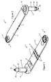
- FIGS 1 and 2 show an animal identification tag 1.
- the tag 1 includes a male pin or punch 2 and a panel 3.
- the panel 3 is formed as a single moulded piece.
- the panel 3 includes a panel portion 4 and a female portion 5, which includes an opening 6.
- the panel 3 also includes a number of recesses 8, which provide a local weakening, helping the panel 3 to bend during application, as will become apparent below.
- the recess 9 may help bending of the tag near the male pin 2, assisting in application of the tag using an applicator, such as the Flexitag applicators available from Allflex.
- the opening 6 is surrounded by a locking flange 10 formed by a number of fingers or projections 11, which project inwards at an angle towards the centre of the opening 6.
- the fingers 11 therefore form a generally conical arrangement or flange 10, with slots or spaces 12 between the fingers 11.
- the locking flange and its fingers are also formed integrally as part of the panel 3, in a single moulded piece. In the embodiment shown there are five fingers 11, but any suitable number of fingers may be used. Preferably between 3 and 8 fingers are used.
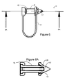
- the male pin 2 has a shaft 15, a base portion 16 (see Figure 5 ) and a distal tip portion 17.
- the base portion 16 is shaped to couple with an opening in the panel 3, preferably by a push-fit although other couplings may be used.
- the base portion 16 includes a base flange 18, and a locking projection 19 defining a groove 20 running around the circumference of the male pin 2.
- a lip 21 on the panel 3 locks into this groove 20 when the male pin is fully inserted into the panel 3.
- the male pin 2 and the panel 3 may therefore be formed as separate components before assembly into the complete tag 1.
- the invention encompasses tags formed by overmoulding or integral forming of the male pin 2 and panel 3.
- the first portion 23 of the panel 3, i.e. that portion surrounding the base of the male pin 2, may be formed as a thicker region than the main part of the panel 3.
- This thicker region provides improved rigidity at the mounting of the male pin 2 to the panel 3, and may provide improved rigidity to that part of the male pin that resides within the thickness of the panel 3.
- This increased rigidity improves the performance of the tag, in particular the application of the tag using a plier or automatic applicator.
- this region may be 5 to 10mm in thickness, preferably around 6-8mm in thickness.
- the thinner sections of the panel 3 may be around 1 to 3 mm, preferably 1 to 2 mm, ideally around 1.25 to 1.45 mm thick.
- the distal or tip portion 17 of the male punch may be formed with a sharp tip with a number of sharp ridges 24 (see Figure 1 ) in order better to penetrate the tissue of an animal's ear during application.
- the tip portion 17 has a generally conical section 25 leading to a locking shoulder 26.
- the locking shoulder 26 cooperates with the locking flange 10 on application of the tag 1 to an animal.
- An applicator receives the tag 1 in a generally U-shape and drives the male pin through the animal's ear.
- the conical section 25 passes through the animal's ear and then into the opening 6, forcing the locking fingers 11 to bend slightly, allowing the locking shoulder 26 to pass beyond the locking fingers 11.
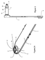
- the locking fingers then return to their natural position, snapping inwards and acting against the locking shoulder 26 as shown in Figure 6 .
- the male pin cannot be retracted from the opening because of the locking of the male pin 2 into the opening 6.
- the tag then forms the closed U-shape as shown in Figure 6 .
- Figure 5 also shows the position of an electronic tag component 30.
- the electronic component 30 sits in a blind bore 31 (i.e. a bore open at only one end) formed in the male pin 2.
- the blind bore may be open at the base of the male pin 2, and may be sealed after insertion of the electronic tag component using any suitable sealant or plug.
- the electronic component 30 may be of any desired construction and may or may not be encapsulated in glass or other suitable encapsulation material.
- the electronic component may include an ID element 32 with an elongate antenna 33 consisting of a conductive wire wound around a core (e.g. copper wire wound around a ferrite core).
- the electronic tag component may be an HDX (half-duplex) RFID (Radiofrequency identification) tag, but other types of electronic tag component may be used.
- Figure 6 shows the ear tag in a closed configuration. During application, the male pin 2 penetrates the animal's ear before entering the female portion of the panel 3, the tag forming a closed loop after application.
- Figure 6A is a cross-section along the line 6A-6A in Figure 6.
- Figure 6A shows the locking projections of the conical flange 10 acting against the locking shoulder 26 to lock the male and female components together.
- Figure 7 shows a further embodiment, in which the first portion 23 of the panel is formed with still greater thickness.
- the male pin has the same length from the opening of the blind bore 31 to the tip. However, the distance from the tip to the plane of the panel 3 is less than in the tag of Figures 1 to 6A . This alters the position of the electronic tag component with respect to the panel 3.
- the first portion 23 is significantly thickened on both sides of the panel 3. This provides further support to the male pin 2. Furthermore, a larger section of the antenna portion of the electronic tag component resides within the thickness of the first portion 23.
- Figure 8 shows the ear tag of Figure 7 in a closed configuration.
- Figure 9 shows a further embodiment of male pin 2, which may be used with a panel 3 such as those described above.
- a frustoconical section 35 extends from the base end of the male pin to a point part way along the male pin 2.
- This frustoconical section may be formed integrally in a single moulding with the male pin 2 and provides improved rigidity, particularly in the region of the electronic tag component antenna, which resides at least partly within the frustoconical section.
- the panel 3 may be made from polyamide or any other suitable plastic material with some flexibility but sufficient rigidity to form the locking projections 11.
- the male pin 2 may be made from a hard plastic material in order to pierce the animal's ear and protect the electronic tag component.
- the arrangement of the locking projections 11 provides a strong, rigid locking mechanism.
- this arrangement also requires more force to be applied in order to engage the male and female components during application of the tag than is the case for tags with a simple resilient female opening.
- These greater forces may create undesirable bending of the male component during application, which may lead to damage to the male pin, or to the electronic tag component housed within the male pin.
- Electronic tag components employing ferrite cores have somewhat fragile antenna sections, particularly when unencapsulated, and such bending of the male pin may damage the antenna, leaving the tag useless.
- the rigidity of the male pin may be improved, or the male pin may be supported, e.g. as described above. Increasing the overall diameter of the male pin is generally undesirable.
- the frustoconical section 35 (see Figure 9 ) and/or supporting thickness in the region 23 (see Figure 5 ) may be used to improve rigidity in the male tag, particularly the base section of the male pin where the antenna portion of the electronic tag component resides.
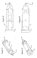
- Figures 10 to 15 illustrate a further embodiment of tag 1.
- the male pin 2 has an asymmetric cross-section, as will be described below.
- the electronic tag component may be contained within the hollow male pin, as described above.
- the panel 3 and other features of the tag are otherwise as described above.
- the asymmetric cross-section can be seen in Figures 10 to 13 , but is most apparent by comparison of the two side views in Figures 14 and 15 .
- the width W of the male pin 2 in the view of Figure 15 is greater than the width W' in Figure 14 .
- the cross-section is preferably generally elliptical or oval.
- the male pin is preferably arranged in the panel 3 such that the longer axis of its cross-section is parallel to the length of the panel 3, or more generally the long axis of the oval is substantially parallel to a line from the male pin to the female portion of the panel.
- This can be achieved reliably by forming the base of the male pin and the cooperating opening and portion 21 of the panel 3 with cooperating asymmetric formations to position the male pin correctly.
- This positioning means that the longer axis is positioned to resist the bending forces created during application of the tag. Less strength is required perpendicular to that axis, as the lateral bending forces are less.
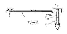
- Figures 16 shows a further embodiment of the invention. This embodiment is similar to that of Figures 7 and 8 , except for the following points.
- the electronic tag component 30 is positioned within a blind bore 31.
- the electronic tag component 30 has a size that is significantly smaller than the bore 31. This results in a space 31' surrounding the electronic tag component 30. This can be contrasted with Figure 7 , where the electronic tag component fits relatively closely within the bore.
- the electronic tag component 30 may simply float within an air space 31' within the bore 31.
- the space 31' may be filled with a fluid, viscous substance (such as a grease or gel), a foam material or the like.
- the substance allows some movement of the electronic tag component 30.
- the space 31' may be sealed by a plug or cap 38.
- the plug or cap 38 may be secured to the male pin by any suitable attachment means, including but not restricted to; laser welding, hot melt welding, gluing or by some other mechanical means.
- the plug or cap may be a plastic component that may be formed separately or optionally may be formed as part of the male pin or panel moulding, Alternatively, the plug or cap may be a resin or similar cap formed in situ.
- the plug or cap closes the bore 31. Further, the plug or cap 31 may seal the bore to prevent ingress of moisture or other contaminants.
- This arrangement provides some freedom of movement of the electronic tag component and helps to cushion the electronic tag component after application of the tag. This will help to prevent damage to the electronic tag component caused by impact or shock stresses. Further, this arrangement limits the bending forces applied to the electronic tag component during application of the tag, because the male pin must bend through a greater angle in order to transmit that bending force to the electronic tag component.
- the RFID transponder In conventional tags, the RFID transponder is generally encapsulated in glass or a similar material. Inside this is a resin that holds the transponder in a fixed position. The encapsulated transponder is a single, rigid component.
- the electronic tag component may be loosely enclosed in a capsule (formed from e.g. plastic, glass or the like), which may be filled with a fluid, viscous substance (such as a grease or gel), a foam material or the like.
- a capsule formed from e.g. plastic, glass or the like
- a fluid, viscous substance such as a grease or gel
- a foam material or the like e.g. foam material
- the capsule forms a close fit to the bore 31 (as in e.g. Figure 7 ), but the electronic tag component has some freedom of movement within the capsule. This provides similar benefits to those of the embodiment of Figure 16 .
- Either of these arrangements of the electronic tag component within the male pin may be used with any of the other embodiments described herein.
- the panel may be free to rotate with respect to the male pin. This may help to prevent damage to the tag or the animal's ear, for example if the panel catches on a branch or the like.
- the Applicant's tag may be particularly suited to identification of sheep, but may also be used for identification of other animals.
Landscapes
- Life Sciences & Earth Sciences (AREA)
- Environmental Sciences (AREA)
- Birds (AREA)
- Zoology (AREA)
- Animal Husbandry (AREA)
- Biodiversity & Conservation Biology (AREA)
- Package Frames And Binding Bands (AREA)
- Feeding And Watering For Cattle Raising And Animal Husbandry (AREA)
- Hooks, Suction Cups, And Attachment By Adhesive Means (AREA)
- User Interface Of Digital Computer (AREA)
- Snaps, Bayonet Connections, Set Pins, And Snap Rings (AREA)
- Clamps And Clips (AREA)
- Details Of Rigid Or Semi-Rigid Containers (AREA)
- Details Of Connecting Devices For Male And Female Coupling (AREA)
Abstract
Description
- The invention relates to animal identification tags.
- Ear tags are used for identification of animals. Existing ear tags are usually formed of plastic and include an identifier such as a number, barcode or electronic ID device. Tags include male components with a punch that is forced through the animal's ear by an applicator tool. The tool brings the male punch into alignment with an opening in a female component. The male punch locks into place in the female component, such that the tag is securely coupled to the animal's ear.
- Known ear tags include the Applicant's "Flexitag" range, which includes a male pin and a single piece panel extending from a first end of the male pin. The other end of the panel includes an opening that receives the other end of the male pin to form a closed loop after application. This is a simple and cost-effective tag. The tag does not include any electronic component. The Applicant has devised further improvements in construction of the tag attachment mechanism and provision of electronic identification capability.
-
WO91/10982 WO95/04455 - It would be desirable to provide an improved animal ear tag or at least to provide the public with a useful choice.
- In a first aspect the invention provides an animal identification ear tag including:
- a male pin having a first end, a second end configured to penetrate an animal's ear and a locking shoulder positioned adjacent the second end; and
- a single piece moulded panel including:
- a first portion formed integrally with the male pin or configured to couple to the first end of the male pin;
- a female portion including:
- an opening configured to receive the second end of the male pin including the locking shoulder, and
- a plurality of locking projections positioned around the periphery of the opening and extending towards the centre of the opening, the locking projections being configured to cooperate with the locking shoulder to lock the male pin to the female portion after application of the tag to an animal's ear; and
- a panel body extending from the first portion to the female portion.
- Preferably the first portion of the moulded panel has a thickness greater than a thickness of the panel body.
- Preferably the male pin has a section that is generally frustoconical in cross-section and extends from its widest point at or near the first end of the male pin to its narrowest point along the length of the male pin, thereby providing increased rigidity at the first end of the male pin.
- Preferably the ear tag includes a blind bore in the male pin and an electronic tag component arranged in the blind bore. Preferably the blind bore is open at the first end of the male pin. Preferably the electronic tag component is an HDX RFID tag component.
- Preferably the electronic tag component is an encapsulated tag component.
- Preferably the electronic tag component includes an elongate antenna that resides at least partly within the thickness of the first portion of the moulded panel.
- Preferably the ear tag includes a blind bore in the male pin and an electronic tag component arranged in the blind bore, the electronic tag component including an elongate antenna that resides at least partly within the frustoconical section.
- Preferably the electronic tag component is smaller than the blind bore, such that the electronic tag component has freedom of movement within the blind bore. Preferably the ear tag further includes a fluid, grease or foam filling a space between the electronic tag component and the wall of the blind bore.
- Alternatively, the electronic tag component may be contained within a capsule received in the blind bore, such that the electronic tag component has freedom of movement within the capsule. Preferably the ear tag further includes a fluid, grease or foam filling a space between the electronic tag component and the internal wall of the capsule.
- Preferably the ear tag is configured to form a closed loop after application to an animal's ear.
- Preferably the locking projections form a generally conical arrangement around the opening.
- Preferably the ear tag includes a plurality of slots separating the locking projections.
- Preferably the ear tag includes between 3 and 8 locking projections.
- Preferably the male pin has an asymmetric cross-section.
- Preferably the male pin has an asymmetric cross-section, with a long axis of the cross-section substantially parallel to a line from the male pin to the female portion.
- Preferably the male pin has a generally oval cross-section with the long axis of the oval substantially parallel to a line from the male pin to the female portion.
- In a second aspect the invention provides an animal identification ear tag including:
- a male pin having a first end, a second end configured to penetrate an animal's ear, a locking shoulder positioned adjacent the second end and a blind bore open at the first end and extending part way along the length of the male pin;
- an elongate electronic tag component arranged within the blind bore, with its antenna element extending towards the first end; and
- a single piece moulded panel including:
- a panel body extending from the first portion and having a first thickness;
- a thickened portion including an opening configured to couple to the first end of the male pin in a push-fit arrangement, the thickened portion having a thickness greater than the first thickness, at least part of an antenna of the electronic tag component residing in the thickness of the thickened portion; and
- female portion including an opening configured to receive the second end of the male pin including the locking shoulder.
- Preferably the thickened portion extends to both sides of the panel body.
- Preferably the electronic tag component is smaller than the blind bore, such that the electronic tag component has freedom of movement within the blind bore. Preferably the ear tag further includes a fluid, grease or foam filling a space between the electronic tag component and the wall of the blind bore.
- Alternatively, the electronic tag component may be contained within a capsule received in the blind bore, such that the electronic tag component has freedom of movement within the capsule. Preferably the ear tag further includes a fluid, grease or foam filling a space between the electronic tag component and the internal wall of the capsule.
- In a third aspect the invention provides an animal identification ear tag including:
- a male pin having a first end, a second end configured to penetrate an animal's ear and a locking shoulder positioned adjacent the second end; and
- a single piece moulded panel including:
- a first portion configured to couple to the first end of the male pin and allowing free rotation of the moulded panel around the male pin;
- a female portion including:
- an opening configured to receive the second end of the male pin including the locking shoulder, and
- a panel body extending from the first portion to the female portion.
- The invention will now be described by way of example only, with reference to the accompanying drawings, in which:
- Figure 1
- is a first perspective view of a tag according to one embodiment;
- Figure 2
- is a second perspective view of the tag of
Figure 1 ; - Figure 2A
- shows the female component of the tag of
Figure 1 in greater detail; - Figure 3
- is a side view of the tag of
Figure 1 ; - Figure 4
- is a front view of the tag of
Figure 1 ; - Figure 5
- is a cross-section along the
line 5'-5' shown inFigure 4 ; - Figure 6
- shows the tag of
Figure 1 after application; - Figure 6A
- is a cross-section along the
line 6A-6A shown inFigure 6 ; - Figure 7
- is a cross-section through a tag according to a second embodiment;
- Figure 8
- is a cross-section through the tag of
Figure 7 , after application; - Figure 9
- is a cross-section through a male pin according to a further embodiment;
- Figure 10
- is a first perspective view of a tag according to a further embodiment;
- Figure 11
- is a second perspective view of the tag of
Figure 10 ; - Figure 12
- is a perspective view of the male pin of the tag of
Figure 10 ; - Figure 13
- is a second perspective view of the male pin of the tag of
Figure 10 ; - Figure 14
- is a side view of the male pin of the tag of
Figure 10 ; - Figure 15
- is a second side view of the male pin of the tag of
Figure 10 ; and - Figure 16
- is a cross-section through a tag according to a further embodiment.
-
Figures 1 and 2 show ananimal identification tag 1. Thetag 1 includes a male pin or punch 2 and apanel 3. Thepanel 3 is formed as a single moulded piece. Thepanel 3 includes apanel portion 4 and afemale portion 5, which includes anopening 6. Thepanel 3 also includes a number ofrecesses 8, which provide a local weakening, helping thepanel 3 to bend during application, as will become apparent below. Similarly therecess 9 may help bending of the tag near themale pin 2, assisting in application of the tag using an applicator, such as the Flexitag applicators available from Allflex. - As shown in
Figures 1 and 2 , and in further detail inFigure 2A , theopening 6 is surrounded by a lockingflange 10 formed by a number of fingers orprojections 11, which project inwards at an angle towards the centre of theopening 6. Thefingers 11 therefore form a generally conical arrangement orflange 10, with slots orspaces 12 between thefingers 11. The locking flange and its fingers are also formed integrally as part of thepanel 3, in a single moulded piece. In the embodiment shown there are fivefingers 11, but any suitable number of fingers may be used. Preferably between 3 and 8 fingers are used. - The
male pin 2 has ashaft 15, a base portion 16 (seeFigure 5 ) and adistal tip portion 17. Thebase portion 16 is shaped to couple with an opening in thepanel 3, preferably by a push-fit although other couplings may be used. As shown inFigure 5 , thebase portion 16 includes abase flange 18, and a lockingprojection 19 defining agroove 20 running around the circumference of themale pin 2. Alip 21 on thepanel 3 locks into thisgroove 20 when the male pin is fully inserted into thepanel 3. Themale pin 2 and thepanel 3 may therefore be formed as separate components before assembly into thecomplete tag 1. However, the invention encompasses tags formed by overmoulding or integral forming of themale pin 2 andpanel 3. - As shown in
Figure 5 , thefirst portion 23 of thepanel 3, i.e. that portion surrounding the base of themale pin 2, may be formed as a thicker region than the main part of thepanel 3. This thicker region provides improved rigidity at the mounting of themale pin 2 to thepanel 3, and may provide improved rigidity to that part of the male pin that resides within the thickness of thepanel 3. This increased rigidity improves the performance of the tag, in particular the application of the tag using a plier or automatic applicator. In some embodiments this region may be 5 to 10mm in thickness, preferably around 6-8mm in thickness. In contrast, the thinner sections of thepanel 3 may be around 1 to 3 mm, preferably 1 to 2 mm, ideally around 1.25 to 1.45 mm thick. - The distal or
tip portion 17 of the male punch may be formed with a sharp tip with a number of sharp ridges 24 (seeFigure 1 ) in order better to penetrate the tissue of an animal's ear during application. - The
tip portion 17 has a generallyconical section 25 leading to a lockingshoulder 26. The lockingshoulder 26 cooperates with the lockingflange 10 on application of thetag 1 to an animal. An applicator receives thetag 1 in a generally U-shape and drives the male pin through the animal's ear. Theconical section 25 passes through the animal's ear and then into theopening 6, forcing the lockingfingers 11 to bend slightly, allowing the lockingshoulder 26 to pass beyond the lockingfingers 11. The locking fingers then return to their natural position, snapping inwards and acting against the lockingshoulder 26 as shown inFigure 6 . The male pin cannot be retracted from the opening because of the locking of themale pin 2 into theopening 6. The tag then forms the closed U-shape as shown inFigure 6 . -
Figure 5 also shows the position of anelectronic tag component 30. Theelectronic component 30 sits in a blind bore 31 (i.e. a bore open at only one end) formed in themale pin 2. The blind bore may be open at the base of themale pin 2, and may be sealed after insertion of the electronic tag component using any suitable sealant or plug. Theelectronic component 30 may be of any desired construction and may or may not be encapsulated in glass or other suitable encapsulation material. In one embodiment the electronic component may include anID element 32 with anelongate antenna 33 consisting of a conductive wire wound around a core (e.g. copper wire wound around a ferrite core). The electronic tag component may be an HDX (half-duplex) RFID (Radiofrequency identification) tag, but other types of electronic tag component may be used. -
Figure 6 shows the ear tag in a closed configuration. During application, themale pin 2 penetrates the animal's ear before entering the female portion of thepanel 3, the tag forming a closed loop after application.Figure 6A is a cross-section along theline 6A-6A inFigure 6. Figure 6A shows the locking projections of theconical flange 10 acting against the lockingshoulder 26 to lock the male and female components together. -
Figure 7 shows a further embodiment, in which thefirst portion 23 of the panel is formed with still greater thickness. In this tag the male pin has the same length from the opening of the blind bore 31 to the tip. However, the distance from the tip to the plane of thepanel 3 is less than in the tag ofFigures 1 to 6A . This alters the position of the electronic tag component with respect to thepanel 3. Thefirst portion 23 is significantly thickened on both sides of thepanel 3. This provides further support to themale pin 2. Furthermore, a larger section of the antenna portion of the electronic tag component resides within the thickness of thefirst portion 23. -
Figure 8 shows the ear tag ofFigure 7 in a closed configuration. -
Figure 9 shows a further embodiment ofmale pin 2, which may be used with apanel 3 such as those described above. In this embodiment afrustoconical section 35 extends from the base end of the male pin to a point part way along themale pin 2. This frustoconical section may be formed integrally in a single moulding with themale pin 2 and provides improved rigidity, particularly in the region of the electronic tag component antenna, which resides at least partly within the frustoconical section. - In any embodiment disclosed herein, the
panel 3 may be made from polyamide or any other suitable plastic material with some flexibility but sufficient rigidity to form the lockingprojections 11. Themale pin 2 may be made from a hard plastic material in order to pierce the animal's ear and protect the electronic tag component. - The arrangement of the locking
projections 11 provides a strong, rigid locking mechanism. However, this arrangement also requires more force to be applied in order to engage the male and female components during application of the tag than is the case for tags with a simple resilient female opening. These greater forces may create undesirable bending of the male component during application, which may lead to damage to the male pin, or to the electronic tag component housed within the male pin. Electronic tag components employing ferrite cores have somewhat fragile antenna sections, particularly when unencapsulated, and such bending of the male pin may damage the antenna, leaving the tag useless. In order to address this problem, the rigidity of the male pin may be improved, or the male pin may be supported, e.g. as described above. Increasing the overall diameter of the male pin is generally undesirable. However, the frustoconical section 35 (seeFigure 9 ) and/or supporting thickness in the region 23 (seeFigure 5 ) may be used to improve rigidity in the male tag, particularly the base section of the male pin where the antenna portion of the electronic tag component resides. -
Figures 10 to 15 illustrate a further embodiment oftag 1. In this embodiment themale pin 2 has an asymmetric cross-section, as will be described below. The electronic tag component may be contained within the hollow male pin, as described above. Thepanel 3 and other features of the tag are otherwise as described above. - The asymmetric cross-section can be seen in
Figures 10 to 13 , but is most apparent by comparison of the two side views inFigures 14 and 15 . The width W of themale pin 2 in the view ofFigure 15 is greater than the width W' inFigure 14 . In this embodiment the cross-section is preferably generally elliptical or oval. - As shown in
Figure 10 , the male pin is preferably arranged in thepanel 3 such that the longer axis of its cross-section is parallel to the length of thepanel 3, or more generally the long axis of the oval is substantially parallel to a line from the male pin to the female portion of the panel. This can be achieved reliably by forming the base of the male pin and the cooperating opening andportion 21 of thepanel 3 with cooperating asymmetric formations to position the male pin correctly. This positioning means that the longer axis is positioned to resist the bending forces created during application of the tag. Less strength is required perpendicular to that axis, as the lateral bending forces are less. -
Figures 16 shows a further embodiment of the invention. This embodiment is similar to that ofFigures 7 and 8 , except for the following points. - In
Figure 16 , theelectronic tag component 30 is positioned within ablind bore 31. In this embodiment theelectronic tag component 30 has a size that is significantly smaller than thebore 31. This results in a space 31' surrounding theelectronic tag component 30. This can be contrasted withFigure 7 , where the electronic tag component fits relatively closely within the bore. - The
electronic tag component 30 may simply float within an air space 31' within thebore 31. However, in preferred embodiments the space 31' may be filled with a fluid, viscous substance (such as a grease or gel), a foam material or the like. Preferably the substance allows some movement of theelectronic tag component 30. Optionally the space 31' may be sealed by a plug orcap 38. The plug orcap 38 may be secured to the male pin by any suitable attachment means, including but not restricted to; laser welding, hot melt welding, gluing or by some other mechanical means. The plug or cap may be a plastic component that may be formed separately or optionally may be formed as part of the male pin or panel moulding, Alternatively, the plug or cap may be a resin or similar cap formed in situ. - The plug or cap closes the
bore 31. Further, the plug orcap 31 may seal the bore to prevent ingress of moisture or other contaminants. - This arrangement provides some freedom of movement of the electronic tag component and helps to cushion the electronic tag component after application of the tag. This will help to prevent damage to the electronic tag component caused by impact or shock stresses. Further, this arrangement limits the bending forces applied to the electronic tag component during application of the tag, because the male pin must bend through a greater angle in order to transmit that bending force to the electronic tag component.
- In conventional tags, the RFID transponder is generally encapsulated in glass or a similar material. Inside this is a resin that holds the transponder in a fixed position. The encapsulated transponder is a single, rigid component.
- In a further alternative, the electronic tag component may be loosely enclosed in a capsule (formed from e.g. plastic, glass or the like), which may be filled with a fluid, viscous substance (such as a grease or gel), a foam material or the like. In this embodiment the capsule forms a close fit to the bore 31 (as in e.g.
Figure 7 ), but the electronic tag component has some freedom of movement within the capsule. This provides similar benefits to those of the embodiment ofFigure 16 . - Either of these arrangements of the electronic tag component within the male pin may be used with any of the other embodiments described herein.
- In any of the embodiments described above, except the asymmetric pin embodiment of
Figures 10-15 , the panel may be free to rotate with respect to the male pin. This may help to prevent damage to the tag or the animal's ear, for example if the panel catches on a branch or the like. - The Applicant's tag may be particularly suited to identification of sheep, but may also be used for identification of other animals.
- While the present invention has been illustrated by the description of the embodiments thereof, and while the embodiments have been described in detail, it is not the intention of the Applicant to restrict or in any way limit the scope of the appended claims to such detail. Additional advantages and modifications will readily appear to those skilled in the art. Therefore, the invention in its broader aspects is not limited to the specific details, representative apparatus and methods, and illustrative examples shown and described. Accordingly, departures may be made from such details without departure from the spirit or scope of the Applicant's general inventive concept.
Claims (15)
- An animal identification ear tag including:i. a male pin having a first end, a second end configured to penetrate an animal's ear and a locking shoulder positioned adjacent the second end; andii. a single piece moulded panel including:a. a first portion formed integrally with the male pin or configured to couple to the first end of the male pin;b. a female portion including:an opening configured to receive the second end of the male pin including the locking shoulder, anda plurality of locking projections positioned around the periphery of the opening and extending towards the centre of the opening, the locking projections being configured to cooperate with the locking shoulder to lock the male pin to the female portion after application of the tag to an animal's ear; andc. a panel body extending from the first portion to the female portion.
- An ear tag as claimed in claim 1, wherein the first portion of the moulded panel has a thickness greater than a thickness of the panel body.
- An ear tag as claimed in any preceding claim wherein the male pin has a section that is generally frustoconical in cross-section and extends from its widest point at or near the first end of the male pin to its narrowest point along the length of the male pin, thereby providing increased rigidity at the first end of the male pin.
- An ear tag as claimed in any preceding claim including a blind bore in the male pin and an electronic tag component arranged in the blind bore, wherein the blind bore is open at the first end of the male pin.
- An ear tag as claimed in claim 4, wherein the electronic tag component includes an elongate antenna that resides at least partly within the thickness of the first portion of the moulded panel.
- An ear tag as claimed in claim 4 or 5, wherein either the electronic tag component is smaller than the blind bore, such that the electronic tag component has freedom of movement within the blind bore, or the electronic tag component is contained within a capsule received in the blind bore, such that the electronic tag component has freedom of movement within the capsule.
- An ear tag as claimed in claim 6, further including a fluid, grease or foam filling a space between the electronic tag component and the wall of the blind bore, or a space between the electronic tag component and the internal wall of the capsule.
- An ear tag as claimed in any preceding claim, configured to form a closed loop after application to an animal's ear.
- An ear tag as claimed in any preceding claim, wherein the locking projections form a generally conical arrangement around the opening.
- An ear tag as claimed in any preceding claim including a plurality of slots separating the locking projections.
- An ear tag as claimed in any preceding claim, including between 3 and 8 locking projections.
- An ear tag as claimed in any preceding claim, wherein the male pin has an asymmetric cross-section, with a long axis of the cross-section substantially parallel to a line from the male pin to the female portion.
- An animal identification ear tag including:i. a male pin having a first end, a second end configured to penetrate an animal's ear, a locking shoulder positioned adjacent the second end and a blind bore open at the first end and extending part way along the length of the male pin;ii. an elongate electronic tag component arranged within the blind bore, with its antenna element extending towards the first end; andiii. a single piece moulded panel including:a. a panel body extending from the first portion and having a first thickness;b. a thickened portion including an opening configured to couple to the first end of the male pin in a push-fit arrangement, the thickened portion having a thickness greater than the first thickness, at least part of an antenna of the electronic tag component residing in the thickness of the thickened portion; andc. female portion including an opening configured to receive the second end of the male pin including the locking shoulder.
- An ear tag as claimed in claim 13 wherein the thickened portion extends to both sides of the panel body.
- An animal identification ear tag including:i. a male pin having a first end, a second end configured to penetrate an animal's ear and a locking shoulder positioned adjacent the second end; andii. a single piece moulded panel including:a. a first portion configured to couple to the first end of the male pin and allowing free rotation of the moulded panel around the male pin;b. a female portion including:an opening configured to receive the second end of the male pin including the locking shoulder, andc. a panel body extending from the first portion to the female portion.
Priority Applications (1)
| Application Number | Priority Date | Filing Date | Title |
|---|---|---|---|
| EP16178356.8A EP3095323B1 (en) | 2012-05-17 | 2013-05-13 | Animal identification ear tag |
Applications Claiming Priority (1)
| Application Number | Priority Date | Filing Date | Title |
|---|---|---|---|
| NZ60004812 | 2012-05-17 |
Related Child Applications (2)
| Application Number | Title | Priority Date | Filing Date |
|---|---|---|---|
| EP16178356.8A Division-Into EP3095323B1 (en) | 2012-05-17 | 2013-05-13 | Animal identification ear tag |
| EP16178356.8A Division EP3095323B1 (en) | 2012-05-17 | 2013-05-13 | Animal identification ear tag |
Publications (2)
| Publication Number | Publication Date |
|---|---|
| EP2664234A1 true EP2664234A1 (en) | 2013-11-20 |
| EP2664234B1 EP2664234B1 (en) | 2016-09-14 |
Family
ID=48444124
Family Applications (2)
| Application Number | Title | Priority Date | Filing Date |
|---|---|---|---|
| EP13167538.1A Active EP2664234B1 (en) | 2012-05-17 | 2013-05-13 | Animal identification tag |
| EP16178356.8A Active EP3095323B1 (en) | 2012-05-17 | 2013-05-13 | Animal identification ear tag |
Family Applications After (1)
| Application Number | Title | Priority Date | Filing Date |
|---|---|---|---|
| EP16178356.8A Active EP3095323B1 (en) | 2012-05-17 | 2013-05-13 | Animal identification ear tag |
Country Status (8)
| Country | Link |
|---|---|
| EP (2) | EP2664234B1 (en) |
| AR (2) | AR091067A1 (en) |
| AU (1) | AU2013205528B9 (en) |
| BR (1) | BR102013012323A2 (en) |
| ES (2) | ES2605599T3 (en) |
| PT (2) | PT2664234T (en) |
| TR (1) | TR201818622T4 (en) |
| UY (1) | UY34814A (en) |
Cited By (24)
| Publication number | Priority date | Publication date | Assignee | Title |
|---|---|---|---|---|
| WO2015158787A1 (en) * | 2014-04-15 | 2015-10-22 | Allflex Europe | An animal identification tag |
| WO2016183616A1 (en) * | 2015-05-21 | 2016-11-24 | Stock Brands Co. Pty Ltd | Animal rfid tag |
| WO2016191794A1 (en) * | 2015-06-03 | 2016-12-08 | Stock Brands Co. Pty Ltd | "animal rfid tag" |
| US10986816B2 (en) | 2014-03-26 | 2021-04-27 | Scr Engineers Ltd. | Livestock location system |
| US10986817B2 (en) | 2014-09-05 | 2021-04-27 | Intervet Inc. | Method and system for tracking health in animal populations |
| US11071279B2 (en) | 2014-09-05 | 2021-07-27 | Intervet Inc. | Method and system for tracking health in animal populations |
| USD990063S1 (en) | 2020-06-18 | 2023-06-20 | S.C.R. (Engineers) Limited | Animal ear tag |
| USD990062S1 (en) | 2020-06-18 | 2023-06-20 | S.C.R. (Engineers) Limited | Animal ear tag |
| US11832587B2 (en) | 2020-06-18 | 2023-12-05 | S.C.R. (Engineers) Limited | Animal tag |
| US11832584B2 (en) | 2018-04-22 | 2023-12-05 | Vence, Corp. | Livestock management system and method |
| US11864529B2 (en) | 2018-10-10 | 2024-01-09 | S.C.R. (Engineers) Limited | Livestock dry off method and device |
| US11960957B2 (en) | 2020-11-25 | 2024-04-16 | Identigen Limited | System and method for tracing members of an animal population |
| US12099893B2 (en) | 2020-07-01 | 2024-09-24 | S.C.R. (Engineers) Limited | Device assignment system and method |
| US12144320B2 (en) | 2019-02-08 | 2024-11-19 | Allflex Australia Pty Ltd | Electronic animal identification tag reader synchronisation |
| US12193413B2 (en) | 2019-02-08 | 2025-01-14 | Allflex Australia Pty Ltd | Electronic animal tag reader |
| US12213449B2 (en) | 2021-01-24 | 2025-02-04 | S.C.R. (Engineers) Limited | Animal marking control system and method |
| US12239098B2 (en) | 2019-02-08 | 2025-03-04 | Allflex Australia Pty Ltd | Determining the location of an animal |
| USD1067554S1 (en) | 2021-04-08 | 2025-03-18 | Allflex Australia Pty Limited | Tag applicator for animals |
| USD1067544S1 (en) | 2021-04-08 | 2025-03-18 | Allflex Australia Pty Limited | Tag applicator for animals |
| US12402599B2 (en) | 2018-10-03 | 2025-09-02 | Allflex Europe Sas | Gripper for manipulating a device for identifying an animal and/or removing tissue from an animal comprising holding means with remote actuation |
| US12402596B2 (en) | 2022-05-03 | 2025-09-02 | S.C.R. (Engineers) Limited | Milk channel and feed inlet coupled thereto, and system and method for conserving wash fluid in a washing process for cleaning a milkmeter system |
| US12409474B2 (en) | 2019-08-28 | 2025-09-09 | S.C.R. (Engineers) Limited | Devices for analysis of a fluid |
| US12555124B2 (en) | 2021-06-03 | 2026-02-17 | S.C.R. (Engineers) Limited | System and method for estimating greenhouse gas emissions in an environment housing an animal population |
| US12580086B2 (en) | 2021-02-09 | 2026-03-17 | S.C.R. (Engineers) Limited | System and method for evaluating the level of harassment of insects on a plurality of animals |
Citations (5)
| Publication number | Priority date | Publication date | Assignee | Title |
|---|---|---|---|---|
| GB1320454A (en) * | 1971-04-13 | 1973-06-13 | Tough Softy Tag Co Ltd | Eartags for marking livestock |
| NL8802209A (en) * | 1988-09-08 | 1990-04-02 | Nedap Nv | Combined label and electronic tag for ear of animal - has electronic capsule with remotely optical readable code encased in centre of pin through ear |
| WO1991010982A1 (en) | 1990-01-11 | 1991-07-25 | Stafford, Katherine, Manheim | Animal ear tags |
| WO1995004455A1 (en) | 1993-08-11 | 1995-02-16 | Rodney Arthur Stafford | Non-snagging animal ear tags |
| US5891156A (en) * | 1996-01-23 | 1999-04-06 | Diehl Ident Gmbh | Device for equipping birds with a transponder |
Family Cites Families (6)
| Publication number | Priority date | Publication date | Assignee | Title |
|---|---|---|---|---|
| GB1053454A (en) * | 1900-01-01 | |||
| IE48707B1 (en) * | 1979-02-09 | 1985-05-01 | Stafford Rodney Arthur | Improvements in and relating to tags,particularly ear tags |
| US4878302A (en) * | 1987-08-13 | 1989-11-07 | Itw New Zealand Limited | Identification tag |
| NL9200027A (en) * | 1992-01-09 | 1993-08-02 | Nedap Nv | Earmark with click-action connection |
| AUPO032296A0 (en) * | 1996-06-06 | 1996-07-04 | Finlayson, Dorothy Elizabeth | Ear tag |
| GB2392138B (en) * | 2002-08-23 | 2004-10-13 | Shearwell Data Ltd | Animal identifiers |
-
2013
- 2013-04-30 AU AU2013205528A patent/AU2013205528B9/en active Active
- 2013-05-13 PT PT131675381T patent/PT2664234T/en unknown
- 2013-05-13 EP EP13167538.1A patent/EP2664234B1/en active Active
- 2013-05-13 EP EP16178356.8A patent/EP3095323B1/en active Active
- 2013-05-13 TR TR2018/18622T patent/TR201818622T4/en unknown
- 2013-05-13 ES ES13167538.1T patent/ES2605599T3/en active Active
- 2013-05-13 PT PT16178356T patent/PT3095323T/en unknown
- 2013-05-13 ES ES16178356T patent/ES2703691T3/en active Active
- 2013-05-16 AR ARP130101699A patent/AR091067A1/en active IP Right Grant
- 2013-05-17 BR BRBR102013012323-4A patent/BR102013012323A2/en not_active IP Right Cessation
- 2013-05-17 UY UY0001034814A patent/UY34814A/en active IP Right Grant
-
2019
- 2019-04-25 AR ARP190101099A patent/AR115366A2/en active IP Right Grant
Patent Citations (5)
| Publication number | Priority date | Publication date | Assignee | Title |
|---|---|---|---|---|
| GB1320454A (en) * | 1971-04-13 | 1973-06-13 | Tough Softy Tag Co Ltd | Eartags for marking livestock |
| NL8802209A (en) * | 1988-09-08 | 1990-04-02 | Nedap Nv | Combined label and electronic tag for ear of animal - has electronic capsule with remotely optical readable code encased in centre of pin through ear |
| WO1991010982A1 (en) | 1990-01-11 | 1991-07-25 | Stafford, Katherine, Manheim | Animal ear tags |
| WO1995004455A1 (en) | 1993-08-11 | 1995-02-16 | Rodney Arthur Stafford | Non-snagging animal ear tags |
| US5891156A (en) * | 1996-01-23 | 1999-04-06 | Diehl Ident Gmbh | Device for equipping birds with a transponder |
Non-Patent Citations (1)
| Title |
|---|
| DATABASE WPI Week 199026, Derwent World Patents Index; AN 1990-199089, XP002702765 * |
Cited By (34)
| Publication number | Priority date | Publication date | Assignee | Title |
|---|---|---|---|---|
| US12213455B2 (en) | 2014-03-26 | 2025-02-04 | S.C.R. (Engineers) Limited | Livestock location system |
| US11963515B2 (en) | 2014-03-26 | 2024-04-23 | S.C.R. (Engineers) Limited | Livestock location system |
| US10986816B2 (en) | 2014-03-26 | 2021-04-27 | Scr Engineers Ltd. | Livestock location system |
| WO2015158787A1 (en) * | 2014-04-15 | 2015-10-22 | Allflex Europe | An animal identification tag |
| GB2542701A (en) * | 2014-04-15 | 2017-03-29 | Allflex Europe | An animal identification tag |
| ES2618010R1 (en) * | 2014-04-15 | 2017-07-10 | Allflex Europe | Mark for animal identification and a method of placing the mark |
| AU2015248885B2 (en) * | 2014-04-15 | 2019-06-13 | Allflex Europe | An animal identification tag |
| GB2542701B (en) * | 2014-04-15 | 2020-12-09 | Allflex Europe | An animal identification tag |
| US10986817B2 (en) | 2014-09-05 | 2021-04-27 | Intervet Inc. | Method and system for tracking health in animal populations |
| US11071279B2 (en) | 2014-09-05 | 2021-07-27 | Intervet Inc. | Method and system for tracking health in animal populations |
| WO2016183616A1 (en) * | 2015-05-21 | 2016-11-24 | Stock Brands Co. Pty Ltd | Animal rfid tag |
| WO2016191794A1 (en) * | 2015-06-03 | 2016-12-08 | Stock Brands Co. Pty Ltd | "animal rfid tag" |
| US12593824B2 (en) | 2018-04-22 | 2026-04-07 | Vence, Corp. | Livestock management system and method |
| US11832584B2 (en) | 2018-04-22 | 2023-12-05 | Vence, Corp. | Livestock management system and method |
| US12402599B2 (en) | 2018-10-03 | 2025-09-02 | Allflex Europe Sas | Gripper for manipulating a device for identifying an animal and/or removing tissue from an animal comprising holding means with remote actuation |
| US11864529B2 (en) | 2018-10-10 | 2024-01-09 | S.C.R. (Engineers) Limited | Livestock dry off method and device |
| US12133507B2 (en) | 2018-10-10 | 2024-11-05 | S.C.R. (Engineers) Limited | Livestock dry off method and device |
| US12239098B2 (en) | 2019-02-08 | 2025-03-04 | Allflex Australia Pty Ltd | Determining the location of an animal |
| US12144320B2 (en) | 2019-02-08 | 2024-11-19 | Allflex Australia Pty Ltd | Electronic animal identification tag reader synchronisation |
| US12193413B2 (en) | 2019-02-08 | 2025-01-14 | Allflex Australia Pty Ltd | Electronic animal tag reader |
| US12409474B2 (en) | 2019-08-28 | 2025-09-09 | S.C.R. (Engineers) Limited | Devices for analysis of a fluid |
| USD990062S1 (en) | 2020-06-18 | 2023-06-20 | S.C.R. (Engineers) Limited | Animal ear tag |
| USD990063S1 (en) | 2020-06-18 | 2023-06-20 | S.C.R. (Engineers) Limited | Animal ear tag |
| US12342790B2 (en) | 2020-06-18 | 2025-07-01 | S.C.R. (Engineers) Limited | Animal tag |
| US11832587B2 (en) | 2020-06-18 | 2023-12-05 | S.C.R. (Engineers) Limited | Animal tag |
| US12099893B2 (en) | 2020-07-01 | 2024-09-24 | S.C.R. (Engineers) Limited | Device assignment system and method |
| US11960957B2 (en) | 2020-11-25 | 2024-04-16 | Identigen Limited | System and method for tracing members of an animal population |
| US12321808B2 (en) | 2020-11-25 | 2025-06-03 | Identigen Limited | System and method for tracing members of an animal population |
| US12213449B2 (en) | 2021-01-24 | 2025-02-04 | S.C.R. (Engineers) Limited | Animal marking control system and method |
| US12580086B2 (en) | 2021-02-09 | 2026-03-17 | S.C.R. (Engineers) Limited | System and method for evaluating the level of harassment of insects on a plurality of animals |
| USD1067544S1 (en) | 2021-04-08 | 2025-03-18 | Allflex Australia Pty Limited | Tag applicator for animals |
| USD1067554S1 (en) | 2021-04-08 | 2025-03-18 | Allflex Australia Pty Limited | Tag applicator for animals |
| US12555124B2 (en) | 2021-06-03 | 2026-02-17 | S.C.R. (Engineers) Limited | System and method for estimating greenhouse gas emissions in an environment housing an animal population |
| US12402596B2 (en) | 2022-05-03 | 2025-09-02 | S.C.R. (Engineers) Limited | Milk channel and feed inlet coupled thereto, and system and method for conserving wash fluid in a washing process for cleaning a milkmeter system |
Also Published As
| Publication number | Publication date |
|---|---|
| UY34814A (en) | 2014-11-28 |
| PT2664234T (en) | 2016-11-25 |
| TR201818622T4 (en) | 2019-01-21 |
| PT3095323T (en) | 2019-01-11 |
| AR115366A2 (en) | 2021-01-13 |
| EP2664234B1 (en) | 2016-09-14 |
| AU2013205528B2 (en) | 2016-09-08 |
| EP3095323B1 (en) | 2018-10-03 |
| BR102013012323A2 (en) | 2015-06-02 |
| EP3095323A1 (en) | 2016-11-23 |
| ES2703691T3 (en) | 2019-03-12 |
| ES2605599T3 (en) | 2017-03-15 |
| AU2013205528B9 (en) | 2017-04-06 |
| AR091067A1 (en) | 2014-12-30 |
Similar Documents
| Publication | Publication Date | Title |
|---|---|---|
| EP2664234B1 (en) | Animal identification tag | |
| CA2779880C (en) | Auricular livestock identification tag | |
| CA2942739A1 (en) | Metal ear tag with overmoulded cover for transponder housing, and method of assembling the same | |
| US9038293B2 (en) | Resinated device for identifying an animal, and corresponding method for manufacturing | |
| AU2015248885B2 (en) | An animal identification tag | |
| US20080042849A1 (en) | Bio implant rfid tag and insertion tool thereof | |
| AU2019236659A1 (en) | Animal identification tag | |
| AU2012269171A1 (en) | Flexible electronic ear tag | |
| JPS6359653B2 (en) | ||
| CN101072499A (en) | Identification device and its manufacturing method | |
| AU2018203668A1 (en) | An animal tag including a transponder casing housed in a cartridge | |
| EP1006787B1 (en) | Ear tag assembly | |
| US20120030977A1 (en) | One-piece ear tag | |
| NZ708992B2 (en) | Animal identification tag | |
| NZ708992A (en) | Animal identification tag | |
| NZ617484B2 (en) | Animal identification tag | |
| CA2796677A1 (en) | Animal identification device | |
| NZ617486B2 (en) | Animal identification tag | |
| NZ610043B (en) | Animal identification tag | |
| EP3007550B1 (en) | Identification kit for the identification of a living being | |
| JP5737902B2 (en) | Drip-proof member for connector and cable structure | |
| NZ724491B2 (en) | An animal identification tag |
Legal Events
| Date | Code | Title | Description |
|---|---|---|---|
| PUAI | Public reference made under article 153(3) epc to a published international application that has entered the european phase |
Free format text: ORIGINAL CODE: 0009012 |
|
| AK | Designated contracting states |
Kind code of ref document: A1 Designated state(s): AL AT BE BG CH CY CZ DE DK EE ES FI FR GB GR HR HU IE IS IT LI LT LU LV MC MK MT NL NO PL PT RO RS SE SI SK SM TR |
|
| AX | Request for extension of the european patent |
Extension state: BA ME |
|
| 17P | Request for examination filed |
Effective date: 20140505 |
|
| RBV | Designated contracting states (corrected) |
Designated state(s): AL AT BE BG CH CY CZ DE DK EE ES FI FR GB GR HR HU IE IS IT LI LT LU LV MC MK MT NL NO PL PT RO RS SE SI SK SM TR |
|
| 17Q | First examination report despatched |
Effective date: 20150302 |
|
| GRAP | Despatch of communication of intention to grant a patent |
Free format text: ORIGINAL CODE: EPIDOSNIGR1 |
|
| INTG | Intention to grant announced |
Effective date: 20160414 |
|
| GRAS | Grant fee paid |
Free format text: ORIGINAL CODE: EPIDOSNIGR3 |
|
| GRAA | (expected) grant |
Free format text: ORIGINAL CODE: 0009210 |
|
| AK | Designated contracting states |
Kind code of ref document: B1 Designated state(s): AL AT BE BG CH CY CZ DE DK EE ES FI FR GB GR HR HU IE IS IT LI LT LU LV MC MK MT NL NO PL PT RO RS SE SI SK SM TR |
|
| REG | Reference to a national code |
Ref country code: GB Ref legal event code: FG4D |
|
| REG | Reference to a national code |
Ref country code: CH Ref legal event code: EP |
|
| REG | Reference to a national code |
Ref country code: IE Ref legal event code: FG4D |
|
| REG | Reference to a national code |
Ref country code: AT Ref legal event code: REF Ref document number: 827866 Country of ref document: AT Kind code of ref document: T Effective date: 20161015 |
|
| REG | Reference to a national code |
Ref country code: DE Ref legal event code: R096 Ref document number: 602013011350 Country of ref document: DE |
|
| REG | Reference to a national code |
Ref country code: PT Ref legal event code: SC4A Ref document number: 2664234 Country of ref document: PT Date of ref document: 20161125 Kind code of ref document: T Free format text: AVAILABILITY OF NATIONAL TRANSLATION Effective date: 20161117 |
|
| REG | Reference to a national code |
Ref country code: RO Ref legal event code: EPE |
|
| REG | Reference to a national code |
Ref country code: NL Ref legal event code: FP |
|
| REG | Reference to a national code |
Ref country code: LT Ref legal event code: MG4D |
|
| PG25 | Lapsed in a contracting state [announced via postgrant information from national office to epo] |
Ref country code: NO Free format text: LAPSE BECAUSE OF FAILURE TO SUBMIT A TRANSLATION OF THE DESCRIPTION OR TO PAY THE FEE WITHIN THE PRESCRIBED TIME-LIMIT Effective date: 20161214 Ref country code: FI Free format text: LAPSE BECAUSE OF FAILURE TO SUBMIT A TRANSLATION OF THE DESCRIPTION OR TO PAY THE FEE WITHIN THE PRESCRIBED TIME-LIMIT Effective date: 20160914 Ref country code: LT Free format text: LAPSE BECAUSE OF FAILURE TO SUBMIT A TRANSLATION OF THE DESCRIPTION OR TO PAY THE FEE WITHIN THE PRESCRIBED TIME-LIMIT Effective date: 20160914 Ref country code: RS Free format text: LAPSE BECAUSE OF FAILURE TO SUBMIT A TRANSLATION OF THE DESCRIPTION OR TO PAY THE FEE WITHIN THE PRESCRIBED TIME-LIMIT Effective date: 20160914 Ref country code: HR Free format text: LAPSE BECAUSE OF FAILURE TO SUBMIT A TRANSLATION OF THE DESCRIPTION OR TO PAY THE FEE WITHIN THE PRESCRIBED TIME-LIMIT Effective date: 20160914 |
|
| REG | Reference to a national code |
Ref country code: AT Ref legal event code: MK05 Ref document number: 827866 Country of ref document: AT Kind code of ref document: T Effective date: 20160914 |
|
| PG25 | Lapsed in a contracting state [announced via postgrant information from national office to epo] |
Ref country code: LV Free format text: LAPSE BECAUSE OF FAILURE TO SUBMIT A TRANSLATION OF THE DESCRIPTION OR TO PAY THE FEE WITHIN THE PRESCRIBED TIME-LIMIT Effective date: 20160914 Ref country code: SE Free format text: LAPSE BECAUSE OF FAILURE TO SUBMIT A TRANSLATION OF THE DESCRIPTION OR TO PAY THE FEE WITHIN THE PRESCRIBED TIME-LIMIT Effective date: 20160914 |
|
| REG | Reference to a national code |
Ref country code: GR Ref legal event code: EP Ref document number: 20160402642 Country of ref document: GR Effective date: 20170130 |
|
| REG | Reference to a national code |
Ref country code: ES Ref legal event code: FG2A Ref document number: 2605599 Country of ref document: ES Kind code of ref document: T3 Effective date: 20170315 |
|
| PG25 | Lapsed in a contracting state [announced via postgrant information from national office to epo] |
Ref country code: EE Free format text: LAPSE BECAUSE OF FAILURE TO SUBMIT A TRANSLATION OF THE DESCRIPTION OR TO PAY THE FEE WITHIN THE PRESCRIBED TIME-LIMIT Effective date: 20160914 |
|
| REG | Reference to a national code |
Ref country code: SK Ref legal event code: T3 Ref document number: E 22701 Country of ref document: SK |
|
| REG | Reference to a national code |
Ref country code: FR Ref legal event code: PLFP Year of fee payment: 5 |
|
| PG25 | Lapsed in a contracting state [announced via postgrant information from national office to epo] |
Ref country code: BE Free format text: LAPSE BECAUSE OF FAILURE TO SUBMIT A TRANSLATION OF THE DESCRIPTION OR TO PAY THE FEE WITHIN THE PRESCRIBED TIME-LIMIT Effective date: 20160914 Ref country code: IS Free format text: LAPSE BECAUSE OF FAILURE TO SUBMIT A TRANSLATION OF THE DESCRIPTION OR TO PAY THE FEE WITHIN THE PRESCRIBED TIME-LIMIT Effective date: 20170114 Ref country code: CZ Free format text: LAPSE BECAUSE OF FAILURE TO SUBMIT A TRANSLATION OF THE DESCRIPTION OR TO PAY THE FEE WITHIN THE PRESCRIBED TIME-LIMIT Effective date: 20160914 Ref country code: PL Free format text: LAPSE BECAUSE OF FAILURE TO SUBMIT A TRANSLATION OF THE DESCRIPTION OR TO PAY THE FEE WITHIN THE PRESCRIBED TIME-LIMIT Effective date: 20160914 Ref country code: SM Free format text: LAPSE BECAUSE OF FAILURE TO SUBMIT A TRANSLATION OF THE DESCRIPTION OR TO PAY THE FEE WITHIN THE PRESCRIBED TIME-LIMIT Effective date: 20160914 Ref country code: BG Free format text: LAPSE BECAUSE OF FAILURE TO SUBMIT A TRANSLATION OF THE DESCRIPTION OR TO PAY THE FEE WITHIN THE PRESCRIBED TIME-LIMIT Effective date: 20161214 Ref country code: AT Free format text: LAPSE BECAUSE OF FAILURE TO SUBMIT A TRANSLATION OF THE DESCRIPTION OR TO PAY THE FEE WITHIN THE PRESCRIBED TIME-LIMIT Effective date: 20160914 |
|
| REG | Reference to a national code |
Ref country code: DE Ref legal event code: R097 Ref document number: 602013011350 Country of ref document: DE |
|
| PLBE | No opposition filed within time limit |
Free format text: ORIGINAL CODE: 0009261 |
|
| STAA | Information on the status of an ep patent application or granted ep patent |
Free format text: STATUS: NO OPPOSITION FILED WITHIN TIME LIMIT |
|
| PG25 | Lapsed in a contracting state [announced via postgrant information from national office to epo] |
Ref country code: DK Free format text: LAPSE BECAUSE OF FAILURE TO SUBMIT A TRANSLATION OF THE DESCRIPTION OR TO PAY THE FEE WITHIN THE PRESCRIBED TIME-LIMIT Effective date: 20160914 |
|
| 26N | No opposition filed |
Effective date: 20170615 |
|
| PG25 | Lapsed in a contracting state [announced via postgrant information from national office to epo] |
Ref country code: LU Free format text: LAPSE BECAUSE OF NON-PAYMENT OF DUE FEES Effective date: 20170531 |
|
| PG25 | Lapsed in a contracting state [announced via postgrant information from national office to epo] |
Ref country code: SI Free format text: LAPSE BECAUSE OF FAILURE TO SUBMIT A TRANSLATION OF THE DESCRIPTION OR TO PAY THE FEE WITHIN THE PRESCRIBED TIME-LIMIT Effective date: 20160914 |
|
| REG | Reference to a national code |
Ref country code: CH Ref legal event code: PL |
|
| PG25 | Lapsed in a contracting state [announced via postgrant information from national office to epo] |
Ref country code: MC Free format text: LAPSE BECAUSE OF FAILURE TO SUBMIT A TRANSLATION OF THE DESCRIPTION OR TO PAY THE FEE WITHIN THE PRESCRIBED TIME-LIMIT Effective date: 20160914 |
|
| PG25 | Lapsed in a contracting state [announced via postgrant information from national office to epo] |
Ref country code: CH Free format text: LAPSE BECAUSE OF NON-PAYMENT OF DUE FEES Effective date: 20170531 Ref country code: LI Free format text: LAPSE BECAUSE OF NON-PAYMENT OF DUE FEES Effective date: 20170531 |
|
| PG25 | Lapsed in a contracting state [announced via postgrant information from national office to epo] |
Ref country code: LU Free format text: LAPSE BECAUSE OF NON-PAYMENT OF DUE FEES Effective date: 20170513 |
|
| REG | Reference to a national code |
Ref country code: FR Ref legal event code: PLFP Year of fee payment: 6 |
|
| PG25 | Lapsed in a contracting state [announced via postgrant information from national office to epo] |
Ref country code: MT Free format text: LAPSE BECAUSE OF NON-PAYMENT OF DUE FEES Effective date: 20170513 |
|
| PG25 | Lapsed in a contracting state [announced via postgrant information from national office to epo] |
Ref country code: AL Free format text: LAPSE BECAUSE OF FAILURE TO SUBMIT A TRANSLATION OF THE DESCRIPTION OR TO PAY THE FEE WITHIN THE PRESCRIBED TIME-LIMIT Effective date: 20160914 |
|
| PG25 | Lapsed in a contracting state [announced via postgrant information from national office to epo] |
Ref country code: HU Free format text: LAPSE BECAUSE OF FAILURE TO SUBMIT A TRANSLATION OF THE DESCRIPTION OR TO PAY THE FEE WITHIN THE PRESCRIBED TIME-LIMIT; INVALID AB INITIO Effective date: 20130513 |
|
| PGFP | Annual fee paid to national office [announced via postgrant information from national office to epo] |
Ref country code: NL Payment date: 20190521 Year of fee payment: 7 |
|
| PGFP | Annual fee paid to national office [announced via postgrant information from national office to epo] |
Ref country code: PT Payment date: 20190508 Year of fee payment: 7 Ref country code: DE Payment date: 20190521 Year of fee payment: 7 Ref country code: IE Payment date: 20190522 Year of fee payment: 7 |
|
| PGFP | Annual fee paid to national office [announced via postgrant information from national office to epo] |
Ref country code: FR Payment date: 20190523 Year of fee payment: 7 |
|
| PGFP | Annual fee paid to national office [announced via postgrant information from national office to epo] |
Ref country code: SK Payment date: 20190425 Year of fee payment: 7 |
|
| PG25 | Lapsed in a contracting state [announced via postgrant information from national office to epo] |
Ref country code: CY Free format text: LAPSE BECAUSE OF NON-PAYMENT OF DUE FEES Effective date: 20160914 |
|
| PG25 | Lapsed in a contracting state [announced via postgrant information from national office to epo] |
Ref country code: MK Free format text: LAPSE BECAUSE OF FAILURE TO SUBMIT A TRANSLATION OF THE DESCRIPTION OR TO PAY THE FEE WITHIN THE PRESCRIBED TIME-LIMIT Effective date: 20160914 |
|
| PGFP | Annual fee paid to national office [announced via postgrant information from national office to epo] |
Ref country code: IT Payment date: 20200528 Year of fee payment: 8 |
|
| REG | Reference to a national code |
Ref country code: DE Ref legal event code: R119 Ref document number: 602013011350 Country of ref document: DE |
|
| REG | Reference to a national code |
Ref country code: NL Ref legal event code: MM Effective date: 20200601 |
|
| REG | Reference to a national code |
Ref country code: SK Ref legal event code: MM4A Ref document number: E 22701 Country of ref document: SK Effective date: 20200513 |
|
| PG25 | Lapsed in a contracting state [announced via postgrant information from national office to epo] |
Ref country code: PT Free format text: LAPSE BECAUSE OF NON-PAYMENT OF DUE FEES Effective date: 20201113 |
|
| PG25 | Lapsed in a contracting state [announced via postgrant information from national office to epo] |
Ref country code: SK Free format text: LAPSE BECAUSE OF NON-PAYMENT OF DUE FEES Effective date: 20200513 Ref country code: NL Free format text: LAPSE BECAUSE OF NON-PAYMENT OF DUE FEES Effective date: 20200601 |
|
| PG25 | Lapsed in a contracting state [announced via postgrant information from national office to epo] |
Ref country code: FR Free format text: LAPSE BECAUSE OF NON-PAYMENT OF DUE FEES Effective date: 20200531 Ref country code: IE Free format text: LAPSE BECAUSE OF NON-PAYMENT OF DUE FEES Effective date: 20200513 |
|
| PG25 | Lapsed in a contracting state [announced via postgrant information from national office to epo] |
Ref country code: DE Free format text: LAPSE BECAUSE OF NON-PAYMENT OF DUE FEES Effective date: 20201201 |
|
| PG25 | Lapsed in a contracting state [announced via postgrant information from national office to epo] |
Ref country code: IT Free format text: LAPSE BECAUSE OF NON-PAYMENT OF DUE FEES Effective date: 20200513 |
|
| PGFP | Annual fee paid to national office [announced via postgrant information from national office to epo] |
Ref country code: TR Payment date: 20230511 Year of fee payment: 11 Ref country code: GR Payment date: 20230522 Year of fee payment: 11 |
|
| PG25 | Lapsed in a contracting state [announced via postgrant information from national office to epo] |
Ref country code: GR Free format text: LAPSE BECAUSE OF NON-PAYMENT OF DUE FEES Effective date: 20241204 |
|
| PG25 | Lapsed in a contracting state [announced via postgrant information from national office to epo] |
Ref country code: GR Free format text: LAPSE BECAUSE OF NON-PAYMENT OF DUE FEES Effective date: 20241204 |
|
| PGFP | Annual fee paid to national office [announced via postgrant information from national office to epo] |
Ref country code: ES Payment date: 20250609 Year of fee payment: 13 |
|
| PGFP | Annual fee paid to national office [announced via postgrant information from national office to epo] |
Ref country code: RO Payment date: 20250415 Year of fee payment: 13 |
|
| PG25 | Lapsed in a contracting state [announced via postgrant information from national office to epo] |
Ref country code: IT Free format text: LAPSE BECAUSE OF NON-PAYMENT OF DUE FEES Effective date: 20210513 |
|
| PGFP | Annual fee paid to national office [announced via postgrant information from national office to epo] |
Ref country code: GB Payment date: 20260320 Year of fee payment: 14 |