EP2663433B1 - Chain link sharpening apparatus - Google Patents
Chain link sharpening apparatus Download PDFInfo
- Publication number
- EP2663433B1 EP2663433B1 EP12755502.7A EP12755502A EP2663433B1 EP 2663433 B1 EP2663433 B1 EP 2663433B1 EP 12755502 A EP12755502 A EP 12755502A EP 2663433 B1 EP2663433 B1 EP 2663433B1
- Authority
- EP
- European Patent Office
- Prior art keywords
- sharpening
- lever arm
- chainsaw
- saw chain
- cutter
- Prior art date
- Legal status (The legal status is an assumption and is not a legal conclusion. Google has not performed a legal analysis and makes no representation as to the accuracy of the status listed.)
- Active
Links
Images







Classifications
-
- B—PERFORMING OPERATIONS; TRANSPORTING
- B23—MACHINE TOOLS; METAL-WORKING NOT OTHERWISE PROVIDED FOR
- B23D—PLANING; SLOTTING; SHEARING; BROACHING; SAWING; FILING; SCRAPING; LIKE OPERATIONS FOR WORKING METAL BY REMOVING MATERIAL, NOT OTHERWISE PROVIDED FOR
- B23D63/00—Dressing the tools of sawing machines or sawing devices for use in cutting any kind of material, e.g. in the manufacture of sawing tools
- B23D63/08—Sharpening the cutting edges of saw teeth
- B23D63/16—Sharpening the cutting edges of saw teeth of chain saws
- B23D63/166—Sharpening the cutting edges of saw teeth of chain saws without removal of the saw chain from the guide bar
- B23D63/168—Sharpening the cutting edges of saw teeth of chain saws without removal of the saw chain from the guide bar the saw chain moving around the guide bar
-
- B—PERFORMING OPERATIONS; TRANSPORTING
- B24—GRINDING; POLISHING
- B24B—MACHINES, DEVICES, OR PROCESSES FOR GRINDING OR POLISHING; DRESSING OR CONDITIONING OF ABRADING SURFACES; FEEDING OF GRINDING, POLISHING, OR LAPPING AGENTS
- B24B3/00—Sharpening cutting edges, e.g. of tools; Accessories therefor, e.g. for holding the tools
- B24B3/02—Sharpening cutting edges, e.g. of tools; Accessories therefor, e.g. for holding the tools of milling cutters
- B24B3/14—Sharpening cutting edges, e.g. of tools; Accessories therefor, e.g. for holding the tools of milling cutters of mortise chain cutters
-
- Y—GENERAL TAGGING OF NEW TECHNOLOGICAL DEVELOPMENTS; GENERAL TAGGING OF CROSS-SECTIONAL TECHNOLOGIES SPANNING OVER SEVERAL SECTIONS OF THE IPC; TECHNICAL SUBJECTS COVERED BY FORMER USPC CROSS-REFERENCE ART COLLECTIONS [XRACs] AND DIGESTS
- Y10—TECHNICAL SUBJECTS COVERED BY FORMER USPC
- Y10T—TECHNICAL SUBJECTS COVERED BY FORMER US CLASSIFICATION
- Y10T83/00—Cutting
- Y10T83/909—Cutter assemblage or cutter element therefor [e.g., chain saw chain]
- Y10T83/917—Having diverse cutting elements
- Y10T83/921—And noncutting depth gauge
Definitions
- Embodiments herein relate to the field of chain saws, and, more specifically, to chain saw components configured to facilitate sharpening of cutter links as they traverse a portion of the guide bar or drive sprocket.
- Chain saws are typically used to fell trees, trim branches, and cut a variety of materials, among other tasks. They generally include an engine enclosed within a housing, a guide bar extending from the housing, and an endless saw chain loop that may include various links such as, but not limited to, cutter links, center links, side links, tie straps, and drive links.
- various links such as, but not limited to, cutter links, center links, side links, tie straps, and drive links.
- One method of sharpening cutter links includes positioning a sharpening element (e.g. an abrasive stone) within the housing of the chain saw.
- the sharpening element may be positioned so as to contact the various saw chain links as they traverse a drive sprocket, typically at high speeds.
- These systems have drawbacks. For example, one or more grooves may be worn into the surface of the sharpening element from the repeated contact of the various saw chain links. These grooves may cause the cutting edge to become deformed during the sharpening process or otherwise negatively impact the ability to maintain a proper cutting edge. Any deformation in the cutting edge may ultimately impact the ability of the chain saw to cut various materials.
- the positioning of the abrasive stone and the high speed at which the cutter links traverse the drive sprocket may result in the unintentional impact of cutter links into the abrasive stone. This tendency may result in an interface that allows undesired movement of the cutter relative to the stone (e.g. tipping or rocking), and/or it may also serve to deform the cutter link, any of which may ultimately result in a decrease in performance.
- US2010005666 describes various components of a chain saw, including saw chain elements, sprockets, and other fixtures, that may facilitate sharpening of cutter links during operation.
- the components may increase stability during sharpening, provide nose mounted sharpening fixtures, and/or facilitate the resizing and/or reshaping of a sharpening element.
- US4385532 describes a sharpening device, for the saw chain of a motor chain saw, with a holding device for a sharpening element which is arranged in the region of the reversing radius and is curved approximately concavely with respect to the center of this reversing radius.
- Coupled may mean that two or more elements are in direct physical or electrical contact. However, “coupled” may also mean that two or more elements are not in direct contact with each other, but yet still cooperate or interact with each other.
- a phrase in the form "A/B” or in the form “A and/or B” means (A), (B), or (A and B).
- a phrase in the form "at least one of A, B, and C” means (A), (B), (C), (A and B), (A and C), (B and C), or (A, B and C).
- a phrase in the form "(A)B” means (B) or (AB) that is, A is an optional element.
- a saw chain is provided with one or more elements configured to facilitate sharpening.
- saw chain may be provided with cutting links including depth gauges configured to provide support, set the depth of cut, and reduce undesirable wear of the sharpening element; center links or drive links including projection elements configured to help stabilize cutter links; and/or conditioning or dresser links configured to condition the sharpening element, including but not limited to helping shape, clean, treat, even out wear, and/or resize the sharpening element.
- cutting elements may be adapted to engage a sharpening element as it traverses a drive sprocket, a nose sprocket, and/or another portion of a guide bar.
- the cutting elements may include a link plate defining a first plane and have a cutting portion twisted out of the first plane about a twist axis, which, in some embodiments, forms an acute angle with a horizontal centerline of the link plate.
- the cutting element may be adapted to be sharpened on an upper edge of the cutting portion to form a cutting edge.
- the cutting element may include one or more depth gauges positioned in front of the cutting edge, for example disposed on the link plate and/or a second link plate opposite the cutter link plate.
- the depth gauges may be configured to engage a groove of a sharpening element to help maintain a desired height, and or to assist in conditioning the sharpening element (e.g. help general groove shape) in conjunction with other elements.
- the depth gauges may minimize and/or correct uneven groove wear, thereby reducing damage to the cutting element.
- projection elements or stabilizer portions may be disposed between cutter links in a saw chain.
- the projection elements may serve to provide additional points of contact with the sharpening stone beyond the typical two points of contact generated with the cutter and a single depth gauge. Achieving three or more points of contact with the sharpening element has been found to provide improved stability and support as the cutter links traverse the drive sprocket and sharpening element. The multiple points of contact also help minimize gaps between the various saw chain components, and consequently, reduce the opportunity for them to engage in adverse impacting with the sharpening element.
- the projection elements may also help to condition the sharpening elements, such as helping to ensure a consistent groove is worn in the sharpening element by removing material between various grooves that might otherwise form on a sharpening element due to sharpening of cutter links.
- dresser links or conditioning links may be used to condition (e.g. refine, reshape, clean and/or otherwise modify) the grinding surface of the sharpening element to allow it to continue to properly and effectively sharpen the cutters.
- the conditioning link may be a separate link having a desired geometrical configuration, or may be a modified cutter link having an appropriate abrasive material adhered thereto to help facilitate reformation and/or maintenance of a surface and/or a groove in the sharpening element.
- Conditioning links may have one or more link plates having portions upstanding that define a plane and an upper surface bent out of the plane. In various embodiments conditioning material may be adhered to the upper surface and/or surrounding surfaces and conform to one or more surface curvatures.
- the conditioning material may clean the sharpening element, or alternatively, facilitate reformation of the sharpening element.
- the rear edge of the conditioning link's upper surface may contact the sharpening element to clean and/or reform the sharpening element.
- a conditioning material may be adhered to a plurality of surfaces adjacent to the rear edge to prevent/reduce breakdown of the conditioning material at the rear edge.
- components other than the various links of a saw chain may be utilized to provide a more effective and reliable sharpening mechanism to sharpen the saw chain as it traverses the guide bar.
- a multi-faceted drive sprocket may be used to increase stability of the cutter link chassis during a sharpening process.
- the multi-faceted drive sprocket may be configured to provide a support surface contact for a cutter link's heel, toe and/or other rail engaging component.
- the support surface in various embodiments, may provide enhanced support to the bottom of the cutter link and reduce the tendency of the cutter to rock during traversal and sharpening.
- the support surface may help position components of the cutter link relative to the stone.
- the support surface may be configured to urge the depth gauge upward relative to the cutter, so that material from the depth gauge is removed. This may help ensure a proper cutting relationship between the cutter and the depth gauge.
- the sharpening element is selectively brought into contact with one or more of the various links of the saw chain by an actuator.
- the actuator may be any suitable mechanism.
- the sharpening element may be disposed on a first end of a lever arm and the actuator may be a handle on a second end of the lever arm.
- the lever arm is coupled to the chain saw at a pivot point between the first end and the second end. When pivoting, as the actuator is moved away from the saw chain, the sharpening element may move toward the saw chain.
- the sharpening element may be disposed at least partially within a housing of the chainsaw, and the actuator may extend from the housing to be accessed by the user.
- the actuator may be located in a position so that the actuator may be actuated by the user while keeping the user's hands on one or more handles of the chainsaw.
- the actuator may be located in the vicinity of a front handle of the chainsaw, such as below the front handle. In this position, the user may actuate the actuator with one or more fingers while keeping one or more remaining fingers on the handle. This position may provide safe control of the chainsaw during sharpening.
- the actuator may be a push slide that engages a pivoting arm.
- the sharpening element is disposed on the pivoting arm.
- the sharpening element may be brought into contact with the saw chain by pushing on the push slide.
- the push slide may be located near the front handle or near the rear handle of the chainsaw.
- the lever arm may travel on a path between a fully unengaged position in which the sharpening element is not in contact with the saw chain and an engaged position in which the sharpening element is in contact with the saw chain.
- the lever arm may be biased, e.g., spring-loaded, to the fully unengaged position.
- the lever arm may include a stop mechanism to prevent the lever arm from traveling past the fully unengaged position as the sharpening element moves away from the saw chain.
- Activation of the actuator e.g., pulling on the handle of the lever arm, may bring the sharpening element into contact with one or more links of the saw chain.
- the sharpening element may grind and/or sharpen one or more of the links of the saw chain, as described in more detail herein.
- the sharpening element may include a sharpening stone coupled with a stone holder.
- the stone holder may be coupled to a mounting surface of the lever arm.
- the sharpening stone may have a curved surface with a center of curvature.
- the sharpening stone may be substantially crescent-shaped.
- the stone holder may have a front surface coupled with the sharpening stone and a rear surface coupled with the mounting surface of the lever arm. The rear surface of the stone holder and the mounting surface of the lever arm may be curved.
- the stone holder may further include a mounting plate for releasably coupling the stone holder to the lever arm.
- the mounting plate may be substantially perpendicular to the front surface of the stone holder and extend rearward, i.e., past the rear surface.
- the mounting plate may releasably couple to the lever arm via screws placed through the side of the lever arm, or via another suitable mechanism.
- the rear surface of the stone holder may have a plurality of contacting portions having contacting surfaces that contact the curved mounting surface of the lever arm.
- the contacting portions may be separated by recessed portions of the rear surface that may not contact the mounting surface of the lever arm.
- the contacting portions of the stone holder may be substantially perpendicular to the mounting plate of the stone holder.
- the recessed portions may also be perpendicular to the mounting plate of the stone holder.
- the recessed portions may be ramped downward toward a peripheral portion of the rear surface (i.e., away from the mounting plate of the stone holder), so that the recessed portions are further recessed from the contacting surfaces as they move away from the mounting plate.
- a width of the stone holder between the front surface and the recessed portions of the rear surface may be greatest at or near the mounting plate and may be lower toward the peripheral portion.
- the ramped configuration of the recessed portion may provide draft to allow the stone holder to be released from a mold during manufacture.
- the contacting portions may provide proper alignment of the sharpening stone on the lever arm. Furthermore, the contacting portions may allow some irregularity in the surface of the recessed portions without detrimentally affecting alignment of the stone holder in the sharpening arm which could otherwise detrimentally affect performance of the sharpening stone.
- the stone holder may be composed of any suitable material or materials.
- the stone holder may be substantially rigid to support the brittle stone against deflection induced by vibration which may damage the sharpening stone.
- the stone holder may be composed of metal, such as aluminum and/or steel.
- various parameters of the sharpening stone may be adjusted depending on the operating conditions of the saw.
- the hardness, density, and/or thickness of the sharpening stone may be adjusted depending on the speed of the saw chain and/or the force that is or may be applied to the actuator to sharpen the chain.
- the saw chain In an electric chainsaw, the saw chain may travel with a slower speed than in a gas-powered chainsaw. Accordingly, a softer, less dense, and/or thicker sharpening stone may be used for an electric chainsaw compared with a gas-powered chainsaw.
- the lever arm may be configured so that the path of the lever arm provides a substantially tangent contact, i.e., a tangent or near tangent contact, between the curved surface of the sharpening stone and the upper edge, i.e., the top plate, of the cutter link on the saw chain.
- the path may be provided by locating the sharpening element on the lever arm so that a path line of the center of curvature of the sharpening stone passes through or just slightly below a center of the drive sprocket. That is, a first distance between the pivot point of the lever arm and the center of curvature of the sharpening element may be substantially equal to or slightly longer than a second distance between the pivot point and the center of the drive sprocket.
- the first distance may be about 0 to about 0.10 inches (2,5 mm) longer than the second distance, or more particularly about 0 to about 0.050 inches (1,3 mm) longer than the second distance, such as about 0 to about 0.030 inches (0,76 mm) longer than the second distance.
- the sharpening element may further include a lead-in feature on an approach surface of the sharpening element to prevent damage to the cutter and sharpening element when the cutter first contacts the sharpening element. After first contact, the curved surface of the sharpening stone may substantially conform to the path of the saw chain and/or dresser links.
- the pivot point of the lever arm may be located so that the sharpening element first contacts the top plate of the cutter element after a forward drive link (i.e., the drive link coupled adjacent to the cutter link in the direction of travel (ahead of the cutter link)), is seated in the gullet of the drive sprocket and the cutter notch is seated on the spur sprocket tooth.
- the sharpening element may first contact the top plate of the cutter element when the forward drive link and a rearward drive link (i.e., the drive link coupled adjacent to the cutter link in the direction opposite the direction of travel (behind the cutter link)), are seated in the gullet of the drive sprocket.
- the heel and toe of the cutter may be in contact with the outer diameter of the rim when the sharpening element first contacts the cutter top plate.
- the sharpening element may be subjected to considerable forces when grinding the various links of the saw chain. In some cases, the forces may cause the sharpening element to move and/or rotate laterally, i.e., away from a plane of the guide bar. The movement and/or rotation of the sharpening element may lessen the effectiveness of the sharpening element, may cause the sharpening element to become misaligned, and/or may damage the cutting edges of the cutter links.
- a retainer guide is coupled to the chain saw to provide lateral support to the sharpening element.
- the lever arm includes a support element, such as an extending edge configured to be at least partially disposed within a groove of the retainer guide.
- the support element may be disposed at or near the end of the lever arm that includes the sharpening element.
- the support element may extend from the back of the lever arm at or near the sharpening element. This location of the support element provides suitable lateral support in conjunction with the lateral support at the pivot point.
- At least a portion of the support element may be disposed within the groove of the retainer guide during the entire path of the lever arm, e.g., from the fully unengaged position to the engaged position. In other embodiments, there may be points along the path of the lever arm in which the support element is not disposed within the groove. However, at least a portion of the support element is disposed within the groove when the lever arm is in the engaged position. Support element may or may not contact the groove.
- the retainer guide provides lateral support to the sharpening element.
- the groove of the retainer guide may be configured to provide lateral support without substantially hindering the travel of the lever arm on its path.
- the lateral support may prevent/reduce rattling of the sharpening element when the sharpening element is grinding on the various links of the saw chain.
- the lateral support may improve the grinding effectiveness of the sharpening element.
- the lateral support may prevent/reduce misalignment of the sharpening element.
- the retainer guide may provide additional lateral support to the support element when the lever arm is in an unengaged position, such as the fully unengaged position.
- the support element and/or retainer guide may be configured so that the support element contacts the groove in an unengaged position.
- the groove may be narrower and/or the support element may have a protrusion or thicker edge that contacts the retainer guide at or near the fully unengaged position.
- the additional support may prevent/reduce lateral movement and/or rattling of the lever arm, thereby reducing potential damage to the lever arm.
- the retainer guide may hold the support element in the unengaged position unless the lever arm is subjected to a reasonable amount of force from the actuator to dislodge it.
- a separate component from the retainer guide may provide the additional lateral support when the lever arm is in an unengaged position.
- a docking feature may receive a rear edge of the support element to provide support to the lever arm when the lever arm is in the unengaged position.
- the lateral support provided by the retainer guide may prevent/reduce damage to the lever arm in the event the saw chain is thrown from the guide bar and impacts the lever arm.
- the end of the lever arm may be vulnerable to damage from a thrown chain because of the distance from the pivot point and the proximity to the guide bar.
- the retainer guide may provide lateral support to diffuse the impact energy of the thrown chain and/or provide a physical obstacle to the chain.
- the retainer guide and/or the support element may be removable. In these embodiments, the retainer and/or support element may be removed and replaced if they become worn or broken. In other embodiments, the support element may be part of the same component as the lever arm.
- the stone holder and/or stone may be removable. In these embodiments, the stone holder and/or stone may be removed and replaced if they become worn or broken. In other embodiments, the stone holder and/or stone may be an integrated component of the lever arm.
- the body of the chainsaw and/or the retainer guide may include a raised lateral support toward the body of the chainsaw.
- the raised lateral support may be raised from the surface of the saw body to provide a gap between the lever arm and the body of the chainsaw. The gap may allow debris from cutting to pass through, thereby preventing/reducing clogging.
- the support element may further include a projected boss that slides against the body of the chainsaw.
- the projected boss may provide support to the support element and/or the lever arm to prevent them from moving and/or rotating toward the body of the chainsaw.
- the support element and retainer guide may be made from any suitable material or materials.
- the vibration on the lever arm from sharpening the saw chain may be from about 500 to 2000 Hertz, which could cause linear friction welding between the support element and the retainer guide with some materials.
- the materials may be chosen to prevent linear friction welding between the support element and retainer guide.
- one or both of the support element and/or retainer guide may be made of a material that prevents and/or resists friction welding, such as steel, aluminum, and/or a thermoset plastic.
- the other component e.g., the other one of the support element or the retainer guide
- the other component may be made from a material that may prevent and/or resist welding (e.g., steel, aluminum, and/or a thermoset plastic).
- a removable sharpening element housing may be secured to the guide bar at a desired location (e.g. the nose) and have a sharpening element actuator that facilitates engagement between the saw chain components and the sharpening element.
- the removable sharpening element housing, sharpening element, and chain component may interface in a similar manner as that encountered when the sharpening element is disposed proximal to the drive sprocket.
- these components may be used individually or in combination to provide a more reliable sharpening mechanism.
- the invention is not to be limited in this regard.
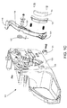
- the chain saw apparatus 100 includes a sharpening element 102, an actuator 116, a guide bar 104, a drive sprocket 106, and a saw chain 108.
- the saw chain 108 may include various link components, for example, a cutter link 110 having a cutting edge 308 that is suited for top surface sharpening, as opposed to in gullet sharpening as is typical in traditional sharpening methods.
- Cutter link 110 may also have a depth gauge 306 that precedes the cutting edge 308 and helps set the depth of cut.
- the chain 108 may also include an opposing tie strap 210 having a forward portion that may be generally shaped similar to the forward portion of the cutter link 110, such that it creates a complementary tie strap depth gauge 212 that corresponds to the cutter link depth gauge 306.
- the chain may further include a center link having a projection element 112, and/or a drive link 114.
- a saw chain may additionally include one or more conditioning links.
- the saw chain 108 may be driven around the guide bar 104 by a drive sprocket 106 during operation.
- the saw chain 108 may include individual cutting links 110 configured to cut an amount of material dependent upon the height of the depth gauge 306 of the cutting link 110, and if used, the complementary opposing tie strap depth gauge 212.
- the sharpening element 102 may be brought into contact with the various links of the saw chain 108, for example the cutter links 110, such that an abrasive surface of the sharpening element may grind a portion of the top surfaces of the chain components, thereby sharpening the cutting edge 308 and setting the depth gauge height of the depth gauge 306 and, if used, the complementary opposing tie strap depth gauge 212 height.
- the sharpening element 102 may initially sharpen a cutting element 110, or alternatively, lower a depth gauge 306, 212 to facilitate a cutting operation, the sharpening element 102 may develop one or more grooves.
- the grooves can lead to a decreased effectiveness of the sharpening element and may cause damage to various saw chain links leading to degradation of the saw chain 108 as a whole. Consequently, one or more links may be provided to increase the effectiveness of the sharpening element 102, as will be described in more detail herein.
- Sharpening element 102 includes a stone holder 103 and a sharpening stone 105. Sharpening stone 105 has a curved surface 117. Actuator 116 may bring the curved surface 117 of sharpening element 102 into contact with one or more links of the saw chain 108 through a lever arm 118. Lever arm 118 may rotate with respect to a body 120 of chain saw apparatus 100 about a pivot point 122. The lever arm 118 may travel on a path between a fully unengaged position in which the sharpening element 102 is not in contact with the saw chain 108 and an engaged position in which the sharpening element 102 is in contact with the saw chain 108.
- Lever arm 118 may be biased, e.g., spring-loaded, to the fully unengaged position. As actuator 116 is pulled away from saw chain 108, sharpening element 102 may move toward saw chain 108. Actuator 116 is located below a front handle 121 of the chainsaw apparatus 100 so that the user may actuate actuator 116 with one or more fingers while maintaining a grip on front handle 121.
- the sharpening element 102 may be subjected to considerable force when in contact with the various links of saw chain 108 while saw chain 108 is in motion, i.e., while saw chain 108 traverses guide bar 104 and/or drive sprocket 106.
- the force may cause sharpening element 102 to move and/or rotate laterally, i.e., perpendicular to the plane of the guide bar.
- the movement and/or rotation of the sharpening element may lessen the effectiveness of the sharpening element, may cause the sharpening element to become misaligned, and/or may damage the cutting edges of the cutter links.
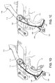
- Figures 1B-C how a chainsaw apparatus 101 that includes a retainer guide 124 on body 120 and a support element 128 on lever arm 118.
- Retainer guide 124 is coupled to the body 120 of chainsaw apparatus 101 and forms a groove 126 with a raised lateral support 136 on the body 120.
- the lever arm 118 includes a support element 128 configured to be at least partially disposed in groove 126.
- at least a portion of support element 128 may be disposed within groove 126 during the entire path of the lever arm 118.
- Support element 128 may or may not contact groove 126.
- Lever arm 118 is biased in an unengaged position by spring 125.
- Retainer guide 124 and support element 128 provide lateral support to sharpening element 102.
- the lateral support may reduce lateral movement and/or rotation of sharpening element 102 when sharpening element 102 is in contact with saw chain 108 as saw chain 108 traverses the drive sprocket 106 and/or guide bar 104.
- the lateral support may improve the effectiveness of sharpening element 102.
- the lateral support may prevent/reduce misalignment of the sharpening element 102.
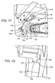
- the sharpening element 102 travels on a path from an unengaged position, shown in Figure 1D , to an engaged position, shown in Figure IE.
- Figure 1F a path line 130 of a center of curvature 132 of the curved surface 117 is shown.
- Path line 130 shows the path of the center of curvature 132 extended past the engaged position.
- Path line 130 passes through a center 134 of drive sprocket 106.
- the curved surface 117 of sharpening element 102 may contact the cutter links of the saw chain (not shown in Figure IF) with substantially tangent contact.
- the substantially tangent contact may facilitate the sharpening process and prevent the top plate of the cutter link from catching the lower edge of the sharpening element, which may otherwise chip the sharpening element and/or damage the cutter top plate.
- the body 120 of chainsaw apparatus 101 further includes a raised lateral support 136 that extends from the surface of body 120. Additionally, support element 128 includes a projected boss 138 that slides against body 120. Both raised lateral support 136 and projected boss 138 provide lateral support to lever arm 118 to prevent lever arm 118 from moving and/or rotating toward body 120. Additionally, raised lateral support 136 and projected boss 138 provide a gap between the lever arm 118 and body 120, which facilitates clearing of debris.
- the sharpening stone 105 may be coupled to the lever arm 118 by stone holder 103.
- Figures 1H-I illustrate perspective views of stone holder 103.
- the stone holder 103 has a curved front surface 140 that couples with the sharpening stone 105 and a curved rear surface 142 that faces a curved mounting surface of the lever arm 118, as shown in Figure 1C .
- the stone holder 103 further includes a mounting plate 144 having holes 146 and 148 for releasably coupling the mounting plate 144 to the side of lever arm 118.
- the mounting plate 144 is substantially perpendicular to the front surface 140 of the stone holder 103.
- the rear surface 142 of the stone holder includes contacting portions 150, 152, and 154.
- the surfaces of contacting portions 150, 152, and 154 contact the mounting surface of the lever arm 118.
- the contacting portions 150, 152, and 154 are separated on rear surface 142 by recessed portions 156 and 158.
- Contacting portions 150 and 154 are disposed at opposite ends of rear surface 142, while contacting portion 152 is disposed substantially in the center of rear surface 142.
- the contacting portions 150, 152, and 154 may provide a proper fit and may distribute the forces from sharpening the saw chain over the mounting surface of the lever arm 118.
- the surfaces of contacting portions 150, 152, and 154 of the stone holder are substantially perpendicular to the mounting plate 144 of stone holder 103.
- the recessed portions 156 and 158 are ramped downward toward a peripheral portion 160 of the rear surface so that the recessed portions 156 and 158 are further recessed from the contacting surfaces 150, 152, and 154 as they move away from the mounting plate 144.
- a width 162 of the stone holder 103 between the front surface 140 and the recessed portions 156 and 158 of the rear surface 142 is greatest where it intersects with mounting plate 144 and tapers lower toward the peripheral portion 160.
- the ramped configuration of the recessed portions 156 and 158 may facilitate removal of the stone holder 103 from a mold during manufacturing, while the contacting portions 150, 152, and 154 may provide alignment and support of the sharpening stone 105.
- the length of saw chain 200 may include cutter links and non-cutting links, for example, top sharp type cutter links 202, opposing tie straps 210, drive links 204, and/or tie straps 206.
- center links and/or drive links 204 may include a projection element or stabilizer portion 208 that is adapted to engage the sharpening element as the chain component traverses the drive sprocket or nose sprocket of the guide bar.
- the length of saw chain may also include other components such as a conditioning link or dresser link 502, illustrated more clearly with reference to Figure 5 .
- the saw chain 200 may be configured in an endless loop and entrained on a guide bar of a chain saw for cutting operations.
- Cutter links 202 may include a variety of operative portions that can individually or collectively assist in improving the sharpening of the cutter link during operation.
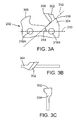
- a cutter link 202 may include a rear portion which defines a cutting portion 302 that may have cutting edges 308 that are ground to a predetermined rake angle, an upstanding portion at the forward end of the cutter link 202 which is generally referred to as a depth gauge 306.
- the cutter link 202 may include a brace portion 304.
- the cutting portion 302 may be a twisted cutter portion that is adapted to be sharpened on an upper edge and/or side portion to form and maintain cutting edge 308.
- the twisted cutter portion may be formed by twisting material integral with the cutter link 202 into a position wherein the cutting edge 308 is substantially transverse to a cutting direction of the utility chain 200.
- substantially transverse may be defined as forming an angle between ten and sixty degrees with respect to a perpendicular line formed with respect to the cutting direction of the utility chain.
- the twisted cutter portion 302 may be formed by a twist that occurs towards a distal end of the material intended to form the cutting portion.
- a twisted cutter portion 302 may include an aggressive twist leaving a portion of the material generally suitable for the cutting portion 302 in plane with the body of cutter link 202.
- material left in the plane of the cutter link 202 may be utilized as a bracing portion 304, which will be discussed in further detail herein.
- a twisted cutter portion 302, leaving material in the plane of the cutter link 202 may have an increased resistance to breakage.
- the cutting portion 302 may be formed by a twist of the upper portion of the cutter link, thereby generating an angle twist axis or chord 312. Having an angled twist chord and/or a brace portion 304 may provide for better support of the cutting edge and allow the cutting portion to better withstand the operational forces imposed in a cutting or sharpening operation.
- the twisted cutter portion 302 may include brace portion 304 and configured to direct cutting forces to the brace portion 304.
- the brace portion 304 may be substantially in plane with the cutter link result from the application of twist axis 312 that is substantially above a center line 310 of the cutting link 202 passing through rivet holes 316A and 316B.
- the twisting axis may be directed at an acute angle 314 toward the toe of the cutting link, thereby helping to form brace portion 304.
- the twisting axis 312 may have an apex 318 or high point at the top of the brace portion 304.
- the apex 318 of the brace portion 304 may have a height of approximately 0.4 inches (10 mm) above the rail engaging heel of the cutter link. In other embodiments, the brace portion may have a height of greater than .250 inches (6,35mm). The inclusion of a brace portion 304 may act to resist breakage of the cutter link 202 by providing a maximum cross section of material that is in plane with the cutting forces.
- twist axis 312 may be angled with respect to center line 310 passing through the centers of rivet holes 316A, 316B.
- the twist axis 312 may form an acute angle 314 in the range of 10 degrees to 70 degrees with respect to the center line 310 (see Figure 3A ), and may be angled toward the toe (as illustrated) or towards trailing links.
- Twisted cutter link 202 may additionally include a depth gauge 306.
- depth gauge 306 may lead the cutting edge 308 into the material to be cut and help limit the depth the cutting edges 308 penetrate into various materials.
- Twisted cutter link 202 as illustrated in Figures 3A-3C may include a first depth gauge portion 306 integral with the twisted cutter link.
- a second depth gauge 212 may be formed on the opposing tie strap 210 and configured to be complementary to the cutter depth gauge 306, thereby forming a double depth gauge. The increased width of the depth gauge not only improves effectiveness of the depth gauge for controlling depth of cut, but also provides better lateral stability for the cutter link 202 during the sharpening operation.
- the position of the first and second depth gauges 306, 212 may be farther from a center of the cutter link than an upper edge of the cutter link is from the center of the cutter link.
- a gap 214 may be formed between the two opposing depth gauges 306, 212.
- the depth gauges may also serve to condition the sharpening element as they traverse the drive sprocket.
- the depth gauges 306, 212 may also serve to, for example, generally square a groove that is worn into a sharpening element, for example, from repeated use.
- the depth gauges may also stabilize the chain from rotational and/or lateral movement when contacting the sharpening element as the depth gauges traverse the drive sprocket. The extra point or points of contact provided by the depth gauges may reduce the likelihood of tipping the chain.
- a cutter link may comprise an aggregate type cutter including an abrasive disposed on an upper surface.
- a build up or coating may need to be removed.
- the coating or upper layer of an abrasive may be removed by the sharpening element. This may, for example, expose a diamond matrix to the material being cut.
- tie straps 206 and center links/drive links 204 are illustrated in accordance with various embodiments.
- Drive links 204 are illustrated with a stabilizing portion 208 that protrudes in a generally upward direction above the chassis of the chain.
- Center links may also include stabilizing portions 208.
- drive links 204 may be configured with a tang portion that engages a drive sprocket and nose sprocket of the chain saw in order to facilitate movement of the chain around the guide bar.
- the drive tang may also engage the groove of the guide bar to facilitate positioning of the saw chain around the periphery of the guide bar.
- the drive tang may be configured in a variety of manners depending upon, for example, the intended application of the saw chain.
- a drive tang may be configured with a clean out portion for wood cutting applications, or without a clean out portion for use in, for example, aggregate applications.
- Projection element 208 may be integral with the drive link 204. Alternatively, the projection element 208 may be separate from the drive link 204 and merely fastened to the drive link.
- the projection element 208 on the drive link may be disposed such that the projection contacts the sharpening element to form one of multiple (three or more) points of contact 402, 404, 406 between the saw chain and the sharpening element.
- the points of contact may include a first point of contact being the cutter contact 404, a second point of contact being the depth gauge contact 402, and a third point of contact being the projection element or stabilizer contact 406. These points of contact may increase stability of the saw chain as it traverses the drive sprocket by, for example, reducing gaps between components that could result in impacting between the sharpening element 410 and the chain components.
- the third point of contact may be made by a second depth gauge disposed on an opposing tie strap, as previously discussed, or by a leading or trailing cutter or depth gauge where, for example, a full sequence chain is utilized. In various embodiments, more than three points of contact may be utilized to further increase stability of the saw chain as it traverses the drive sprocket.
- the projection element 208 may also be configured to remove a portion of material from a sharpening element 410 to facilitate effective sharpening over the life of the chain.
- a cutter element 302 may form a groove or wear pattern in a sharpening element 410 through successive contact with the sharpening element 410.
- Various features of the cutter link such as depth gauges, may additionally form grooves.
- a saw chain may utilize left-hand and right-hand cutter links and depth gauges. The left-hand and right-hand depth gauges may form two grooves within a larger groove formed by the cutting edge of the cutter links.
- the projection element 208 may be configured to remove the material located between the two grooves formed by the depth gauges, which may in turn enhance the effectiveness of the sharpening during the life of the chain.
- the projection element 208 may act to better conform the position of the chain chassis (e.g. saw chain), and thereby the cutters, to the shape of the sharpening element, such as an abrasive stone or sharpening device.
- the projection element 208 may minimize impact damage to various links as they traverse the drive sprocket and contact the abrasive stone 410.
- the position of the projection may be disposed farther from the center of the drive link than the depth gauge is from the center of the cutter link.
- the depth gauges may be farther from the center of the cutter link than the cutting edge of the cutting link is from the center, in order to ensure an appropriate depth of cut is created as the cutter link traverses the sharpening element.
- chain 200 may also include a conditioning link 502, in accordance with various embodiments to condition (e.g. reform, treat, clean and/or maintain) the sharpening element 410.
- a conditioning link 502 in accordance with various embodiments to condition (e.g. reform, treat, clean and/or maintain) the sharpening element 410.
- a cutter link 202 traverses a drive sprocket 700 and contacts a sharpening element 410, for example an abrasive stone, a groove may be worn into the stone.
- the groove may become improperly formed or deformed (e.g. rounded edges) over time for a variety of reasons.
- a deformed groove may lead to a reduction in the sharpening effectiveness of the sharpening element 410. Therefore, in various embodiments, a conditioning link 502 having a desired geometrical configuration may be included in the saw chain 200 and help facilitate reformation and/or maintenance of a groove in the sharpening element 410.
- conditioning link 502 may include a first link plate 504 having a portion upstanding that defines a first plane.
- An upper surface 506, integral with the upstanding portion, may be bent out of the first plane and, in various embodiments, include a surface curvature.
- Conditioning link 502 may additionally include second link plate 508 disposed opposite the first link plate 504 having similar characteristics.
- the first upper surface 506 and the second upper surface 510 may extend generally away from a centerline of the utility chain.
- the conditioning links may include at least one of a curved upper surface extending from a leading edge to a trailing edge, a tapered surface extending from one edge to another edge, a tapered leading edge, a tapered trailing edge, or a combination thereof.
- the upper surfaces 506 and 510 may be configured with a conditioning material adhered to their upper surfaces, wherein the conditioning material is configured to condition a sharpening element.
- the conditioning material in various embodiments, may clean, shape, condition, and/or reform a sharpening element.
- the conditioning material may be an abrasive, such as diamond elements, or alternatively, a cleaning agent configured to clean debris out of a sharpening element.
- the upper surface 506 of the conditioning link 502 may be disposed at a predetermined height relative to other links within the saw chain.
- the conditioning link 502 may be configured with a height below an estimated height of a cutter link at the end of its useful life. This may reduce the tendency of the conditioning link 502 to impact the material being cut throughout the lifetime of the chain 200.
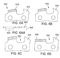
- the conditioning or dresser links 600 may take a variety of configurations, some of which are illustrated in Figures 6A-6D , and 6AA.
- the dresser links may be left-handed links, right-handed links, or alternatively, continuous body links.
- the dresser links may be generally configured similar to a typical cutting link, and have an upper surface 602 containing a conditioning material, such as a diamond impregnated coating.
- the dresser links may have a delayed contact gauge(e.g.
- a depth gauge, raker, or other protrusion 604 leading the abrasive surface 602 that is designed to delay contact between the dresser link diamond abrasives and the stone as it rounds the drive sprocket until the chain has created a shallow groove in the stone. This may delay unintended wear of the abrasive material and prevent premature wear of the sharpening element.
- the curvature, shape, length, width and other geometrical factors of the abrasive carrying surface of the dresser link may be altered as desired in order to help improve the conditioning performance of the link.
- the abrasive carrying surface 602 of the dresser link 600 may extend generally laterally outward, e.g. generally transverse of the direction of travel, such that it creates a path that is wider than the path of the cutter links.
- the outward extension 606 of each side of the abrasive surface may be in the range of .010" to .030" (0,25 to 0,76 mm) more than a corresponding side of a cutter.
- the side of the abrasive surface 602 may be less than the width of the cutter element 202.
- the overall width of the abrasive surface (including a single conditioning link or a right hand and left hand pair) may be in the range of .16" to 0.40" (4,1 to 10 mm) in hand held saws and 0.28" and 0.63" (7,1 and 16 mm) in mechanical harvester machines. Providing a wider path of the abrasive surface can provide for a wider groove in the sharpening element 410 so the cutting edge corners do not contact the groove bottom radii or the side walls of the groove.
- the shape of the dresser link 600 may be configured such that only a portion of the abrasive surface is adapted to contact the sharpening segment, and as the abrasive surface 602 wears away, fresh portions of the abrasive surface may be adapted to engage the surface of the sharpening element 410.
- This may provide for a longer life of the chain 200, sharpening segment and/or abrasive dresser segments.
- a surface curvature of the upper surface 602 may be tapered towards the back, such that the forward portion 610 of the dresser link wears first (e.g. Figure 6A ). As the forward portion 610 wears away, fresh abrasive material will encounter the sharpening element 410. Further, in this configuration, more support is provided for the abrasive material as the abrasive behind the forward portion 610 may act as a support.
- the abrasive surface orientation may be tapered in the front, such that the first contact with the sharpening element is at the rear portion 608 of the dresser link 600.
- the engagement surface moves progressively forward, and in some embodiments lower, as the abrasive material is worn away (e.g. diamonds are lost or worn). Wearing in such a manner presents new abrasive components (e.g. diamonds) to the sharpening element 410.
- it may also allow the dresser link 600 to reduce in height as the cutters 202 also reduce in height with each sharpening, thereby enhancing performance.
- Such a configuration may also allow the abrasive material to engage the sharpening element 410 in a smoother less abrupt manner; however, the abrasive elements may be more inclined to separate from the dresser link for lack of support.
- the upper surface may be generally curved, or may taper in the front and in the rear in an arcuate fashion. These configurations may allow the middle portion as the portion that engages the sharpening element first, and as it wears, abrasive elements in front of and behind the wear portion condition the sharpening element. In various embodiments, the upper surface may taper from one end to another end, such as from the leading edge to the trialing edge, or visa versa.
- the conditioning link 900 may have two exposed surfaces 902A, 902B with an abrasive coating for conditioning the sharpening element 410.
- the dresser link 900 may have a second dresser surface.
- the dresser surfaces may be configured as right hand links, left hand links, or a single dresser link that includes a first side and an opposing second side with the abrasive surface coupling the two together.
- the conditioning link 1000 may include a first link plate having a substantially unitary surface 1002 extending over a center-line of a utility chain 200.
- the substantially unitary surface may be configured to expose an abrasive material to the sharpening element 410.
- the surface 1002 may be configured to provide a generally planar surface that has a width substantially similar to or less than a kerf of the cutting chain 200.
- the conditioning link 1000 may include a depth gauge 1004A disposed in front of the substantially unitary surface 1002. Additionally, and similar to an embodiment of the cutter link 202, the conditioning link 1000 may similarly include a tie strap disposed opposite the conditioning link 1000, which includes a complimentary depth gauge 1004B.
- the density and placement of the diamond or other abrasive elements may be controlled as desired. For example, having a relatively low density of abrasive elements may provide for a uniform conditioning of the sharpening element groove, surface or other interface.
- the abrasive elements may be stacked vertically in one portion of the cutter link to allow for conditioning of a surface or groove having a varied profile.
- Abrasive elements may be disposed about the perimeter and part of the sides of the dresser link surface in order to ensure proper groove width, for example.
- the drive sprocket may include radially directed sprocket teeth 702 forming a plurality of gullets configured to engage one or more drive links.
- the radially directed sprocket teeth 702 may be disposed co-axially between two support rims 704.
- the support rims 704 may include a plurality of facets 706 configured to support various links as they traverse the sprocket and sharpening element.
- the multi-faceted drive sprocket 700 may include one or more facets having a variable length. In one embodiment, the length may be generally equal to or slightly greater than the footprint length of various links within the saw chain. This may provide adequate support for the links and additionally provide a mechanism to resist slipping or rocking during traversal of the drive sprocket.
- the plurality of facets 706 may be geometrically configured to engage more than one point of the bottom of various saw chain links.
- the facets may be substantially flat, or alternatively, may include various features, such as a step 708 or slope, to facilitate positioning of the saw chain links as they traverses the drive sprocket 700.
- the supportive surface may reduce the tendency of various links to rock or otherwise engage in undesirable movement, and may better position the cutting edges of a cutter link for sharpening by the sharpening member.
- the facets 706 of the drive sprocket 700 may include a lip 710.
- the lip 710 may provide support to the cutter link and resist reward movement caused by the frictional forces generated by the interface between the sharpening element and the cutting link components (e.g. cutting elements and/or depth gauges).
- the lip 710 may be of a variety of geometrical configurations
- the faceted drive sprocket 700 can also be configured so that the cutter link is oriented to expose more of the cutter's depth gauge to the action of the sharpening element than the cutting edge, as illustrated by the exposed depth gauge 712 in Figure 7 . This may result in more material being removed from the depth gauge relative to the cutting edge 308, and consequently, maintain the depth gauge setting throughout successive sharpening of the cutter links.
- the saw chain sharpening fixture may include one or more locating members 802, such as one or more locating pins, configured to align a guide bar to the saw chain sharpening fixture 800, a sharpening element 804 configured to sharpen one or more cutting links as they traverse a nose of the guide bar, and an actuator 808 configured to selectively bring the sharpening element 804 into contact with the one or more cutting links.
- locating members 802 such as one or more locating pins
- the bar mounted saw chain sharpening fixture may include a housing 806 configured to attach to a nose of saw chain guide bar in a clamping manner.
- the housing may include a locating member 802 such as one or more alignment pins that are configured to mesh with corresponding slots or holes in the guide bar. With a guide bar correctly positioned on the locating member 802, the housing fixture may clamp onto the guide bar and allow the chain to freely move about the nose of the guide bar. A tension clamp may engage the locating member to ensure relatively solid connection such that movement of the housing relative to the guide bar does not occur during a sharpening operation.
- an actuator 808 may be used to bring a sharpening element 804 into contact with the cutting elements.
- the actuation device 808 may include a biased lever (e.g. spring loaded) communicatively coupled to the sharpening element.
- a biased lever e.g. spring loaded
- the actuation device 808 may be configured so as to resist a motion that would bring the sharpening element 804 into contact with the saw chains.
- a spring may force the sharpening element 804 against the distal end of the housing 806.
- the spring may be configured with a spring constant equivalent or substantially equivalent to a weight of a chain saw. Consequently, only a slight force may be needed to bring the sharpening element 804 into contact with the saw chain links.
- actuation devices 808 may be utilized.
- the sharpening element may be carried by a removable cartridge that has a coupling pattern allowing the cartridge to be removed and replaced when the sharpening element is worn.
Landscapes
- Engineering & Computer Science (AREA)
- Mechanical Engineering (AREA)
- Processing Of Stones Or Stones Resemblance Materials (AREA)
- Sawing (AREA)
Description
- Embodiments herein relate to the field of chain saws, and, more specifically, to chain saw components configured to facilitate sharpening of cutter links as they traverse a portion of the guide bar or drive sprocket.
- Chain saws are typically used to fell trees, trim branches, and cut a variety of materials, among other tasks. They generally include an engine enclosed within a housing, a guide bar extending from the housing, and an endless saw chain loop that may include various links such as, but not limited to, cutter links, center links, side links, tie straps, and drive links. Through use, the cutting surfaces of various links may become dulled and worn. As the cutting surfaces experience wear, an increased amount of force is required to produce a desired cut, which is inefficient and consumes energy. Therefore, cutter links of saw chains are periodically sharpened to maintain efficiency in a cutting operation.
- One method of sharpening cutter links includes positioning a sharpening element (e.g. an abrasive stone) within the housing of the chain saw. The sharpening element may be positioned so as to contact the various saw chain links as they traverse a drive sprocket, typically at high speeds. These systems, however, have drawbacks. For example, one or more grooves may be worn into the surface of the sharpening element from the repeated contact of the various saw chain links. These grooves may cause the cutting edge to become deformed during the sharpening process or otherwise negatively impact the ability to maintain a proper cutting edge. Any deformation in the cutting edge may ultimately impact the ability of the chain saw to cut various materials.
- Additionally, the positioning of the abrasive stone and the high speed at which the cutter links traverse the drive sprocket may result in the unintentional impact of cutter links into the abrasive stone. This tendency may result in an interface that allows undesired movement of the cutter relative to the stone (e.g. tipping or rocking), and/or it may also serve to deform the cutter link, any of which may ultimately result in a decrease in performance.
-
US2010005666 describes various components of a chain saw, including saw chain elements, sprockets, and other fixtures, that may facilitate sharpening of cutter links during operation. In various embodiments, the components may increase stability during sharpening, provide nose mounted sharpening fixtures, and/or facilitate the resizing and/or reshaping of a sharpening element. -
US4385532 describes a sharpening device, for the saw chain of a motor chain saw, with a holding device for a sharpening element which is arranged in the region of the reversing radius and is curved approximately concavely with respect to the center of this reversing radius. -
US3526156 describes saw chain sharpening means. - Accordingly the present teaching provides a saw chain sharpening fixture as defined in claim 1. Advantageous features are provided in the dependent claims.
- Embodiments will be readily understood by the following detailed description in conjunction with the accompanying drawings. Embodiments are illustrated by way of example and not by way of limitation in the figures of the accompanying drawings.
-
Figure 1A illustrates a chainsaw in accordance with various embodiments; -
Figure 1B illustrates an alternative embodiment of a chainsaw in accordance with various embodiments; -
Figure 1C illustrates an exploded view of a lever arm in accordance with various embodiments; -
Figure 1D illustrates a lever arm in the fully unengaged position in accordance with various embodiments; - Figure IE illustrates a lever arm in the engaged position in accordance with various embodiments;
-
Figure 1F illustrates a lever arm in accordance with various embodiments; -
Figure 1G illustrates a partial view of a retainer guide in accordance with various embodiments; -
Figures 1H-1I illustrate perspective views of a stone holder in accordance with various embodiments; -
Figure 2 illustrates a section of a saw chain in accordance with various embodiments; -
Figures 3A-3C illustrate a cutter link in accordance with various embodiments; -
Figure 4 illustrates a saw chain and sharpening stone interface in accordance with various embodiments; -
Figure 5 illustrates a saw chain and sharpening stone interface in accordance with various embodiments; -
Figures 6A-6D and 6AA illustrate dresser links in accordance with various embodiments; -
Figure 7 illustrates a drive sprocket, saw chain and sharpening stone interface in accordance with various embodiments; -
Figures 8A-8B illustrate a sharpening housing suited for nose coupling in accordance with various embodiments; -
Figure 9 illustrates a dresser link in accordance with various embodiments; and -
Figure 10 illustrates another dresser link in accordance with various embodiments. - In the following detailed description, reference is made to the accompanying drawings which form a part hereof, and in which are shown by way of illustration embodiments that may be practiced. It is to be understood that other embodiments may be utilized and structural or logical changes may be made without departing from the scope of the appended claims.
- Therefore, the following detailed description is not to be taken in a limiting sense, and the scope of embodiments is defined by the appended claims.
- Various operations may be described as multiple discrete operations in turn, in a manner that may be helpful in understanding embodiments; however, the order of description should not be construed to imply that these operations are order dependent.
- The description may use perspective-based descriptions such as up/down, back/front, and top/bottom. Such descriptions are merely used to facilitate the discussion and are not intended to restrict the application of disclosed embodiments.
- The terms "coupled" and "connected," along with their derivatives, may be used. It should be understood that these terms are not intended as synonyms for each other. Rather, in particular embodiments, "connected" may be used to indicate that two or more elements are in direct physical or electrical contact with each other. "Coupled" may mean that two or more elements are in direct physical or electrical contact. However, "coupled" may also mean that two or more elements are not in direct contact with each other, but yet still cooperate or interact with each other.
- For the purposes of the description, a phrase in the form "A/B" or in the form "A and/or B" means (A), (B), or (A and B). For the purposes of the description, a phrase in the form "at least one of A, B, and C" means (A), (B), (C), (A and B), (A and C), (B and C), or (A, B and C). For the purposes of the description, a phrase in the form "(A)B" means (B) or (AB) that is, A is an optional element.
- The description may use the terms "embodiment" or "embodiments," which may each refer to one or more of the same or different embodiments. Furthermore, the terms "comprising," "including," "having," and the like, as used with respect to embodiments, are synonymous.
- In various embodiments of the present disclosure, methods, apparatuses, and systems for providing a more effective and reliable sharpening mechanism for saw chains are provided. In exemplary embodiments, a saw chain is provided with one or more elements configured to facilitate sharpening. For example, saw chain may be provided with cutting links including depth gauges configured to provide support, set the depth of cut, and reduce undesirable wear of the sharpening element; center links or drive links including projection elements configured to help stabilize cutter links; and/or conditioning or dresser links configured to condition the sharpening element, including but not limited to helping shape, clean, treat, even out wear, and/or resize the sharpening element.
- In various embodiments, cutting elements may be adapted to engage a sharpening element as it traverses a drive sprocket, a nose sprocket, and/or another portion of a guide bar. The cutting elements may include a link plate defining a first plane and have a cutting portion twisted out of the first plane about a twist axis, which, in some embodiments, forms an acute angle with a horizontal centerline of the link plate. The cutting element may be adapted to be sharpened on an upper edge of the cutting portion to form a cutting edge. In various embodiments, the cutting element may include one or more depth gauges positioned in front of the cutting edge, for example disposed on the link plate and/or a second link plate opposite the cutter link plate. The depth gauges may be configured to engage a groove of a sharpening element to help maintain a desired height, and or to assist in conditioning the sharpening element (e.g. help general groove shape) in conjunction with other elements. In various embodiments, the depth gauges may minimize and/or correct uneven groove wear, thereby reducing damage to the cutting element.
- In various embodiments, projection elements or stabilizer portions, referred to interchangeably, may be disposed between cutter links in a saw chain. The projection elements may serve to provide additional points of contact with the sharpening stone beyond the typical two points of contact generated with the cutter and a single depth gauge. Achieving three or more points of contact with the sharpening element has been found to provide improved stability and support as the cutter links traverse the drive sprocket and sharpening element. The multiple points of contact also help minimize gaps between the various saw chain components, and consequently, reduce the opportunity for them to engage in adverse impacting with the sharpening element. The projection elements may also help to condition the sharpening elements, such as helping to ensure a consistent groove is worn in the sharpening element by removing material between various grooves that might otherwise form on a sharpening element due to sharpening of cutter links.
- In various embodiments, dresser links or conditioning links may be used to condition (e.g. refine, reshape, clean and/or otherwise modify) the grinding surface of the sharpening element to allow it to continue to properly and effectively sharpen the cutters. The conditioning link may be a separate link having a desired geometrical configuration, or may be a modified cutter link having an appropriate abrasive material adhered thereto to help facilitate reformation and/or maintenance of a surface and/or a groove in the sharpening element. Conditioning links may have one or more link plates having portions upstanding that define a plane and an upper surface bent out of the plane. In various embodiments conditioning material may be adhered to the upper surface and/or surrounding surfaces and conform to one or more surface curvatures. The conditioning material may clean the sharpening element, or alternatively, facilitate reformation of the sharpening element. In some embodiments, the rear edge of the conditioning link's upper surface may contact the sharpening element to clean and/or reform the sharpening element. In some such embodiments, a conditioning material may be adhered to a plurality of surfaces adjacent to the rear edge to prevent/reduce breakdown of the conditioning material at the rear edge.
- In various other embodiments, components other than the various links of a saw chain may be utilized to provide a more effective and reliable sharpening mechanism to sharpen the saw chain as it traverses the guide bar. For example, a multi-faceted drive sprocket may be used to increase stability of the cutter link chassis during a sharpening process. The multi-faceted drive sprocket may be configured to provide a support surface contact for a cutter link's heel, toe and/or other rail engaging component. The support surface, in various embodiments, may provide enhanced support to the bottom of the cutter link and reduce the tendency of the cutter to rock during traversal and sharpening. Additionally, the support surface may help position components of the cutter link relative to the stone. For example, the support surface may be configured to urge the depth gauge upward relative to the cutter, so that material from the depth gauge is removed. This may help ensure a proper cutting relationship between the cutter and the depth gauge.
- According to the invention, the sharpening element is selectively brought into contact with one or more of the various links of the saw chain by an actuator. The actuator may be any suitable mechanism. For example, the sharpening element may be disposed on a first end of a lever arm and the actuator may be a handle on a second end of the lever arm. The lever arm is coupled to the chain saw at a pivot point between the first end and the second end. When pivoting, as the actuator is moved away from the saw chain, the sharpening element may move toward the saw chain. The sharpening element may be disposed at least partially within a housing of the chainsaw, and the actuator may extend from the housing to be accessed by the user. The actuator may be located in a position so that the actuator may be actuated by the user while keeping the user's hands on one or more handles of the chainsaw. For example, the actuator may be located in the vicinity of a front handle of the chainsaw, such as below the front handle. In this position, the user may actuate the actuator with one or more fingers while keeping one or more remaining fingers on the handle. This position may provide safe control of the chainsaw during sharpening.
- In other embodiments, the actuator may be a push slide that engages a pivoting arm. The sharpening element is disposed on the pivoting arm. In these embodiments, the sharpening element may be brought into contact with the saw chain by pushing on the push slide. In some embodiments, the push slide may be located near the front handle or near the rear handle of the chainsaw.
- The lever arm may travel on a path between a fully unengaged position in which the sharpening element is not in contact with the saw chain and an engaged position in which the sharpening element is in contact with the saw chain. The lever arm may be biased, e.g., spring-loaded, to the fully unengaged position. Similarly, the lever arm may include a stop mechanism to prevent the lever arm from traveling past the fully unengaged position as the sharpening element moves away from the saw chain. Activation of the actuator, e.g., pulling on the handle of the lever arm, may bring the sharpening element into contact with one or more links of the saw chain. When the saw chain is traversing the guide bar while the lever arm is in the engaged position, the sharpening element may grind and/or sharpen one or more of the links of the saw chain, as described in more detail herein.
- In various embodiments, the sharpening element may include a sharpening stone coupled with a stone holder. The stone holder may be coupled to a mounting surface of the lever arm. In some embodiments, the sharpening stone may have a curved surface with a center of curvature. For example, the sharpening stone may be substantially crescent-shaped. The stone holder may have a front surface coupled with the sharpening stone and a rear surface coupled with the mounting surface of the lever arm. The rear surface of the stone holder and the mounting surface of the lever arm may be curved. The stone holder may further include a mounting plate for releasably coupling the stone holder to the lever arm. The mounting plate may be substantially perpendicular to the front surface of the stone holder and extend rearward, i.e., past the rear surface. The mounting plate may releasably couple to the lever arm via screws placed through the side of the lever arm, or via another suitable mechanism.
- In various embodiments, the rear surface of the stone holder may have a plurality of contacting portions having contacting surfaces that contact the curved mounting surface of the lever arm. The contacting portions may be separated by recessed portions of the rear surface that may not contact the mounting surface of the lever arm.
- The contacting portions of the stone holder may be substantially perpendicular to the mounting plate of the stone holder. In some embodiments, the recessed portions may also be perpendicular to the mounting plate of the stone holder. In other embodiments, the recessed portions may be ramped downward toward a peripheral portion of the rear surface (i.e., away from the mounting plate of the stone holder), so that the recessed portions are further recessed from the contacting surfaces as they move away from the mounting plate. In this ramped configuration, a width of the stone holder between the front surface and the recessed portions of the rear surface may be greatest at or near the mounting plate and may be lower toward the peripheral portion. The ramped configuration of the recessed portion may provide draft to allow the stone holder to be released from a mold during manufacture. The contacting portions may provide proper alignment of the sharpening stone on the lever arm. Furthermore, the contacting portions may allow some irregularity in the surface of the recessed portions without detrimentally affecting alignment of the stone holder in the sharpening arm which could otherwise detrimentally affect performance of the sharpening stone.
- The stone holder may be composed of any suitable material or materials. In some embodiments, the stone holder may be substantially rigid to support the brittle stone against deflection induced by vibration which may damage the sharpening stone. For example, the stone holder may be composed of metal, such as aluminum and/or steel.
- In some embodiments, various parameters of the sharpening stone may be adjusted depending on the operating conditions of the saw. For example, the hardness, density, and/or thickness of the sharpening stone may be adjusted depending on the speed of the saw chain and/or the force that is or may be applied to the actuator to sharpen the chain. In an electric chainsaw, the saw chain may travel with a slower speed than in a gas-powered chainsaw. Accordingly, a softer, less dense, and/or thicker sharpening stone may be used for an electric chainsaw compared with a gas-powered chainsaw.
- The lever arm may be configured so that the path of the lever arm provides a substantially tangent contact, i.e., a tangent or near tangent contact, between the curved surface of the sharpening stone and the upper edge, i.e., the top plate, of the cutter link on the saw chain. The path may be provided by locating the sharpening element on the lever arm so that a path line of the center of curvature of the sharpening stone passes through or just slightly below a center of the drive sprocket. That is, a first distance between the pivot point of the lever arm and the center of curvature of the sharpening element may be substantially equal to or slightly longer than a second distance between the pivot point and the center of the drive sprocket. Such a path may facilitate the sharpening process and prevent the top plate of the cutter link from catching the lower edge of the sharpening element, which may otherwise chip the sharpening element and/or damage the cutter top plate. In some embodiments, the first distance may be about 0 to about 0.10 inches (2,5 mm) longer than the second distance, or more particularly about 0 to about 0.050 inches (1,3 mm) longer than the second distance, such as about 0 to about 0.030 inches (0,76 mm) longer than the second distance.
In some embodiments, the sharpening element may further include a lead-in feature on an approach surface of the sharpening element to prevent damage to the cutter and sharpening element when the cutter first contacts the sharpening element. After first contact, the curved surface of the sharpening stone may substantially conform to the path of the saw chain and/or dresser links. - Additionally, in some embodiments, the pivot point of the lever arm may be located so that the sharpening element first contacts the top plate of the cutter element after a forward drive link (i.e., the drive link coupled adjacent to the cutter link in the direction of travel (ahead of the cutter link)), is seated in the gullet of the drive sprocket and the cutter notch is seated on the spur sprocket tooth. In some embodiments, the sharpening element may first contact the top plate of the cutter element when the forward drive link and a rearward drive link (i.e., the drive link coupled adjacent to the cutter link in the direction opposite the direction of travel (behind the cutter link)), are seated in the gullet of the drive sprocket. In embodiments including a rim sprocket, the heel and toe of the cutter may be in contact with the outer diameter of the rim when the sharpening element first contacts the cutter top plate.
- The sharpening element may be subjected to considerable forces when grinding the various links of the saw chain. In some cases, the forces may cause the sharpening element to move and/or rotate laterally, i.e., away from a plane of the guide bar. The movement and/or rotation of the sharpening element may lessen the effectiveness of the sharpening element, may cause the sharpening element to become misaligned, and/or may damage the cutting edges of the cutter links.
- According to the invention a retainer guide is coupled to the chain saw to provide lateral support to the sharpening element. The lever arm includes a support element, such as an extending edge configured to be at least partially disposed within a groove of the retainer guide. For example, the support element may be disposed at or near the end of the lever arm that includes the sharpening element. For example, the support element may extend from the back of the lever arm at or near the sharpening element. This location of the support element provides suitable lateral support in conjunction with the lateral support at the pivot point.
- In some embodiments, at least a portion of the support element may be disposed within the groove of the retainer guide during the entire path of the lever arm, e.g., from the fully unengaged position to the engaged position. In other embodiments, there may be points along the path of the lever arm in which the support element is not disposed within the groove. However, at least a portion of the support element is disposed within the groove when the lever arm is in the engaged position. Support element may or may not contact the groove.
- The retainer guide provides lateral support to the sharpening element. The groove of the retainer guide may be configured to provide lateral support without substantially hindering the travel of the lever arm on its path. The lateral support may prevent/reduce rattling of the sharpening element when the sharpening element is grinding on the various links of the saw chain. The lateral support may improve the grinding effectiveness of the sharpening element. Furthermore, the lateral support may prevent/reduce misalignment of the sharpening element.
- Repeated lateral movement of the lever arm, such as movement that may be caused by vibration from operation of the chainsaw, may damage the lever arm, especially at or near the pivot point. Accordingly, in some embodiments, the retainer guide may provide additional lateral support to the support element when the lever arm is in an unengaged position, such as the fully unengaged position. For example, the support element and/or retainer guide may be configured so that the support element contacts the groove in an unengaged position. In some embodiments, the groove may be narrower and/or the support element may have a protrusion or thicker edge that contacts the retainer guide at or near the fully unengaged position. The additional support may prevent/reduce lateral movement and/or rattling of the lever arm, thereby reducing potential damage to the lever arm. The retainer guide may hold the support element in the unengaged position unless the lever arm is subjected to a reasonable amount of force from the actuator to dislodge it.
- In some embodiments, a separate component from the retainer guide may provide the additional lateral support when the lever arm is in an unengaged position. For example, a docking feature may receive a rear edge of the support element to provide support to the lever arm when the lever arm is in the unengaged position.
- Additionally, the lateral support provided by the retainer guide may prevent/reduce damage to the lever arm in the event the saw chain is thrown from the guide bar and impacts the lever arm. The end of the lever arm may be vulnerable to damage from a thrown chain because of the distance from the pivot point and the proximity to the guide bar. However, the retainer guide may provide lateral support to diffuse the impact energy of the thrown chain and/or provide a physical obstacle to the chain.
- In some embodiments, the retainer guide and/or the support element may be removable. In these embodiments, the retainer and/or support element may be removed and replaced if they become worn or broken. In other embodiments, the support element may be part of the same component as the lever arm.
- In an embodiment, the stone holder and/or stone may be removable. In these embodiments, the stone holder and/or stone may be removed and replaced if they become worn or broken. In other embodiments, the stone holder and/or stone may be an integrated component of the lever arm.
- In some embodiments, the body of the chainsaw and/or the retainer guide may include a raised lateral support toward the body of the chainsaw. The raised lateral support may be raised from the surface of the saw body to provide a gap between the lever arm and the body of the chainsaw. The gap may allow debris from cutting to pass through, thereby preventing/reducing clogging.
- In some embodiments, the support element may further include a projected boss that slides against the body of the chainsaw. The projected boss may provide support to the support element and/or the lever arm to prevent them from moving and/or rotating toward the body of the chainsaw.
- In various embodiments, the support element and retainer guide may be made from any suitable material or materials. In some embodiments, the vibration on the lever arm from sharpening the saw chain may be from about 500 to 2000 Hertz, which could cause linear friction welding between the support element and the retainer guide with some materials. Accordingly, in some embodiments, the materials may be chosen to prevent linear friction welding between the support element and retainer guide. For example, one or both of the support element and/or retainer guide may be made of a material that prevents and/or resists friction welding, such as steel, aluminum, and/or a thermoset plastic. If either the support element or retainer guide is composed of a material that may be susceptible to linear friction welding, such as a thermoformed plastic, the other component (e.g., the other one of the support element or the retainer guide) may be made from a material that may prevent and/or resist welding (e.g., steel, aluminum, and/or a thermoset plastic).
- In various embodiments, a removable sharpening element housing may be secured to the guide bar at a desired location (e.g. the nose) and have a sharpening element actuator that facilitates engagement between the saw chain components and the sharpening element. The removable sharpening element housing, sharpening element, and chain component may interface in a similar manner as that encountered when the sharpening element is disposed proximal to the drive sprocket.
- As will be discussed in more detail herein, these components may be used individually or in combination to provide a more reliable sharpening mechanism. The invention is not to be limited in this regard.
- Referring to
Figures 1A-3 , various embodiments of a chain saw are discussed. A chain sawapparatus 100, sawchain 200, and sawchain component 202 are illustrated, in accordance with various embodiments. The chain sawapparatus 100 includes a sharpeningelement 102, anactuator 116, aguide bar 104, adrive sprocket 106, and asaw chain 108. Thesaw chain 108 may include various link components, for example, acutter link 110 having acutting edge 308 that is suited for top surface sharpening, as opposed to in gullet sharpening as is typical in traditional sharpening methods.Cutter link 110 may also have adepth gauge 306 that precedes thecutting edge 308 and helps set the depth of cut. Thechain 108 may also include an opposingtie strap 210 having a forward portion that may be generally shaped similar to the forward portion of thecutter link 110, such that it creates a complementary tiestrap depth gauge 212 that corresponds to the cutterlink depth gauge 306. The chain may further include a center link having aprojection element 112, and/or adrive link 114. Various other links and/or components may be included without deviating from the scope of this disclosure. For example, a saw chain may additionally include one or more conditioning links. - In accordance with various embodiments, the
saw chain 108 may be driven around theguide bar 104 by adrive sprocket 106 during operation. Thesaw chain 108 may includeindividual cutting links 110 configured to cut an amount of material dependent upon the height of thedepth gauge 306 of thecutting link 110, and if used, the complementary opposing tiestrap depth gauge 212. As the cuttinglinks 110 traverse theguide bar 104 and contact material, they may experience wear resulting in a decreased ability to cut. Consequently, a sharpeningelement 102 is positioned proximate to thesaw chain 108 and coupled to anactuator 116. Upon actuation of theactuator 116, the sharpeningelement 102 may be brought into contact with the various links of thesaw chain 108, for example the cutter links 110, such that an abrasive surface of the sharpening element may grind a portion of the top surfaces of the chain components, thereby sharpening thecutting edge 308 and setting the depth gauge height of thedepth gauge 306 and, if used, the complementary opposing tiestrap depth gauge 212 height. - While the sharpening
element 102 may initially sharpen acutting element 110, or alternatively, lower adepth gauge element 102 may develop one or more grooves. The grooves can lead to a decreased effectiveness of the sharpening element and may cause damage to various saw chain links leading to degradation of thesaw chain 108 as a whole. Consequently, one or more links may be provided to increase the effectiveness of the sharpeningelement 102, as will be described in more detail herein. - Sharpening
element 102 includes astone holder 103 and a sharpeningstone 105. Sharpeningstone 105 has acurved surface 117.Actuator 116 may bring thecurved surface 117 of sharpeningelement 102 into contact with one or more links of thesaw chain 108 through alever arm 118.Lever arm 118 may rotate with respect to abody 120 of chain sawapparatus 100 about apivot point 122. Thelever arm 118 may travel on a path between a fully unengaged position in which the sharpeningelement 102 is not in contact with thesaw chain 108 and an engaged position in which the sharpeningelement 102 is in contact with thesaw chain 108.Lever arm 118 may be biased, e.g., spring-loaded, to the fully unengaged position. Asactuator 116 is pulled away fromsaw chain 108, sharpeningelement 102 may move towardsaw chain 108.Actuator 116 is located below afront handle 121 of thechainsaw apparatus 100 so that the user may actuate actuator 116 with one or more fingers while maintaining a grip onfront handle 121. - The sharpening
element 102 may be subjected to considerable force when in contact with the various links ofsaw chain 108 whilesaw chain 108 is in motion, i.e., whilesaw chain 108 traverses guidebar 104 and/or drivesprocket 106. In some cases, the force may cause sharpeningelement 102 to move and/or rotate laterally, i.e., perpendicular to the plane of the guide bar. The movement and/or rotation of the sharpening element may lessen the effectiveness of the sharpening element, may cause the sharpening element to become misaligned, and/or may damage the cutting edges of the cutter links. - Accordingly,
Figures 1B-C how achainsaw apparatus 101 that includes aretainer guide 124 onbody 120 and asupport element 128 onlever arm 118.Retainer guide 124 is coupled to thebody 120 ofchainsaw apparatus 101 and forms agroove 126 with a raisedlateral support 136 on thebody 120. Thelever arm 118 includes asupport element 128 configured to be at least partially disposed ingroove 126. In some embodiments, at least a portion ofsupport element 128 may be disposed withingroove 126 during the entire path of thelever arm 118. In other embodiments, there may be points along the path of thelever arm 118 in which thesupport element 128 is not disposed withingroove 126. However, at least a portion ofsupport element 128 is disposed within thegroove 126 when thelever arm 118 is in the engaged position.Support element 128 may or may not contactgroove 126.Lever arm 118 is biased in an unengaged position byspring 125. -
Retainer guide 124 andsupport element 128 provide lateral support to sharpeningelement 102. The lateral support may reduce lateral movement and/or rotation of sharpeningelement 102 when sharpeningelement 102 is in contact withsaw chain 108 assaw chain 108 traverses thedrive sprocket 106 and/or guidebar 104. The lateral support may improve the effectiveness of sharpeningelement 102. Furthermore, the lateral support may prevent/reduce misalignment of the sharpeningelement 102. - The sharpening
element 102 travels on a path from an unengaged position, shown inFigure 1D , to an engaged position, shown in Figure IE. Referring now toFigure 1F , apath line 130 of a center ofcurvature 132 of thecurved surface 117 is shown.Path line 130 shows the path of the center ofcurvature 132 extended past the engaged position.Path line 130 passes through acenter 134 ofdrive sprocket 106. Accordingly, when thelever arm 118 is in the engaged position, thecurved surface 117 of sharpeningelement 102 may contact the cutter links of the saw chain (not shown in Figure IF) with substantially tangent contact. The substantially tangent contact may facilitate the sharpening process and prevent the top plate of the cutter link from catching the lower edge of the sharpening element, which may otherwise chip the sharpening element and/or damage the cutter top plate. - Referring now to
Figure 1G , thebody 120 ofchainsaw apparatus 101 further includes a raisedlateral support 136 that extends from the surface ofbody 120. Additionally,support element 128 includes a projectedboss 138 that slides againstbody 120. Both raisedlateral support 136 and projectedboss 138 provide lateral support to leverarm 118 to preventlever arm 118 from moving and/or rotating towardbody 120. Additionally, raisedlateral support 136 and projectedboss 138 provide a gap between thelever arm 118 andbody 120, which facilitates clearing of debris. - As discussed above, the sharpening
stone 105 may be coupled to thelever arm 118 bystone holder 103.Figures 1H-I illustrate perspective views ofstone holder 103. Thestone holder 103 has a curvedfront surface 140 that couples with the sharpeningstone 105 and a curvedrear surface 142 that faces a curved mounting surface of thelever arm 118, as shown inFigure 1C . Thestone holder 103 further includes a mountingplate 144 havingholes plate 144 to the side oflever arm 118. The mountingplate 144 is substantially perpendicular to thefront surface 140 of thestone holder 103. - The
rear surface 142 of the stone holder includes contactingportions portions lever arm 118. The contactingportions rear surface 142 by recessedportions portions rear surface 142, while contactingportion 152 is disposed substantially in the center ofrear surface 142. The contactingportions lever arm 118. - As depicted in
Figures 1H-1I , the surfaces of contactingportions plate 144 ofstone holder 103. The recessedportions peripheral portion 160 of the rear surface so that the recessedportions surfaces plate 144. In this ramped configuration, awidth 162 of thestone holder 103 between thefront surface 140 and the recessedportions rear surface 142 is greatest where it intersects with mountingplate 144 and tapers lower toward theperipheral portion 160. The ramped configuration of the recessedportions stone holder 103 from a mold during manufacturing, while the contactingportions stone 105. - Referring now to
Figure 2 , a length ofsaw chain 200 is illustrated, in accordance with various embodiments. The length ofsaw chain 200 may include cutter links and non-cutting links, for example, top sharptype cutter links 202, opposing tie straps 210, drivelinks 204, and/or tie straps 206. In various embodiments, center links and/or drivelinks 204 may include a projection element orstabilizer portion 208 that is adapted to engage the sharpening element as the chain component traverses the drive sprocket or nose sprocket of the guide bar. The length of saw chain may also include other components such as a conditioning link ordresser link 502, illustrated more clearly with reference toFigure 5 . Thesaw chain 200 may be configured in an endless loop and entrained on a guide bar of a chain saw for cutting operations. - Cutter links 202 may include a variety of operative portions that can individually or collectively assist in improving the sharpening of the cutter link during operation. For example, with reference to
Figures 3A-3C , acutter link 202 may include a rear portion which defines a cuttingportion 302 that may have cuttingedges 308 that are ground to a predetermined rake angle, an upstanding portion at the forward end of thecutter link 202 which is generally referred to as adepth gauge 306. In various embodiments, thecutter link 202 may include abrace portion 304. - In various embodiments, the cutting
portion 302 may be a twisted cutter portion that is adapted to be sharpened on an upper edge and/or side portion to form and maintaincutting edge 308. The twisted cutter portion may be formed by twisting material integral with thecutter link 202 into a position wherein thecutting edge 308 is substantially transverse to a cutting direction of theutility chain 200. In various embodiments, substantially transverse may be defined as forming an angle between ten and sixty degrees with respect to a perpendicular line formed with respect to the cutting direction of the utility chain. Unlike prior twisted cutters, thetwisted cutter portion 302 may be formed by a twist that occurs towards a distal end of the material intended to form the cutting portion. For example, atwisted cutter portion 302 may include an aggressive twist leaving a portion of the material generally suitable for the cuttingportion 302 in plane with the body ofcutter link 202. In various embodiments, material left in the plane of thecutter link 202, may be utilized as a bracingportion 304, which will be discussed in further detail herein. Atwisted cutter portion 302, leaving material in the plane of thecutter link 202, may have an increased resistance to breakage. - In various embodiments, the cutting
portion 302 may be formed by a twist of the upper portion of the cutter link, thereby generating an angle twist axis orchord 312. Having an angled twist chord and/or abrace portion 304 may provide for better support of the cutting edge and allow the cutting portion to better withstand the operational forces imposed in a cutting or sharpening operation. - In various embodiments, the
twisted cutter portion 302 may includebrace portion 304 and configured to direct cutting forces to thebrace portion 304. Thebrace portion 304 may be substantially in plane with the cutter link result from the application oftwist axis 312 that is substantially above acenter line 310 of thecutting link 202 passing throughrivet holes acute angle 314 toward the toe of the cutting link, thereby helping to formbrace portion 304. The twistingaxis 312 may have an apex 318 or high point at the top of thebrace portion 304. In various embodiments, theapex 318 of thebrace portion 304 may have a height of approximately 0.4 inches (10 mm) above the rail engaging heel of the cutter link. In other embodiments, the brace portion may have a height of greater than .250 inches (6,35mm). The inclusion of abrace portion 304 may act to resist breakage of thecutter link 202 by providing a maximum cross section of material that is in plane with the cutting forces. - In various embodiments, such that the
twist axis 312 may be angled with respect tocenter line 310 passing through the centers ofrivet holes twist axis 312 may form anacute angle 314 in the range of 10 degrees to 70 degrees with respect to the center line 310 (seeFigure 3A ), and may be angled toward the toe (as illustrated) or towards trailing links. -
Twisted cutter link 202 may additionally include adepth gauge 306. In various embodiments,depth gauge 306 may lead thecutting edge 308 into the material to be cut and help limit the depth the cutting edges 308 penetrate into various materials.Twisted cutter link 202, as illustrated inFigures 3A-3C may include a firstdepth gauge portion 306 integral with the twisted cutter link. In addition, asecond depth gauge 212 may be formed on the opposingtie strap 210 and configured to be complementary to thecutter depth gauge 306, thereby forming a double depth gauge. The increased width of the depth gauge not only improves effectiveness of the depth gauge for controlling depth of cut, but also provides better lateral stability for thecutter link 202 during the sharpening operation. This may result in a more consistent sharpening of the cutting edge, and may further help condition the sharpening element. In various embodiments, the position of the first and second depth gauges 306, 212 may be farther from a center of the cutter link than an upper edge of the cutter link is from the center of the cutter link. - As illustrated in
Figure 2 , with asecond depth gauge 212 positioned on the opposingtie strap 210 of the twistedcutter link 202, agap 214 may be formed between the two opposing depth gauges 306, 212. In various embodiments, in addition to limiting the amount of material cut by the twistedcutter portion 302, the depth gauges may also serve to condition the sharpening element as they traverse the drive sprocket. In various embodiments, the depth gauges 306, 212 may also serve to, for example, generally square a groove that is worn into a sharpening element, for example, from repeated use. Additionally, the depth gauges may also stabilize the chain from rotational and/or lateral movement when contacting the sharpening element as the depth gauges traverse the drive sprocket. The extra point or points of contact provided by the depth gauges may reduce the likelihood of tipping the chain. - In various other embodiments, a cutter link may comprise an aggregate type cutter including an abrasive disposed on an upper surface. In order to expose an abrasive disposed on the upper surface, a build up or coating may need to be removed. The coating or upper layer of an abrasive may be removed by the sharpening element. This may, for example, expose a diamond matrix to the material being cut.
- Still with reference to
Figure 2 , tie straps 206 and center links/drivelinks 204 are illustrated in accordance with various embodiments. Drivelinks 204 are illustrated with a stabilizingportion 208 that protrudes in a generally upward direction above the chassis of the chain. Center links may also include stabilizingportions 208. As illustrated, drivelinks 204 may be configured with a tang portion that engages a drive sprocket and nose sprocket of the chain saw in order to facilitate movement of the chain around the guide bar. The drive tang may also engage the groove of the guide bar to facilitate positioning of the saw chain around the periphery of the guide bar. The drive tang may be configured in a variety of manners depending upon, for example, the intended application of the saw chain. For example, a drive tang may be configured with a clean out portion for wood cutting applications, or without a clean out portion for use in, for example, aggregate applications.Projection element 208 may be integral with thedrive link 204. Alternatively, theprojection element 208 may be separate from thedrive link 204 and merely fastened to the drive link. - Referring to
Figure 4 , theprojection element 208 on the drive link may be disposed such that the projection contacts the sharpening element to form one of multiple (three or more) points ofcontact cutter contact 404, a second point of contact being thedepth gauge contact 402, and a third point of contact being the projection element orstabilizer contact 406. These points of contact may increase stability of the saw chain as it traverses the drive sprocket by, for example, reducing gaps between components that could result in impacting between the sharpeningelement 410 and the chain components. In various embodiments, the third point of contact may be made by a second depth gauge disposed on an opposing tie strap, as previously discussed, or by a leading or trailing cutter or depth gauge where, for example, a full sequence chain is utilized. In various embodiments, more than three points of contact may be utilized to further increase stability of the saw chain as it traverses the drive sprocket. - The
projection element 208 may also be configured to remove a portion of material from a sharpeningelement 410 to facilitate effective sharpening over the life of the chain. In various embodiments, acutter element 302 may form a groove or wear pattern in a sharpeningelement 410 through successive contact with the sharpeningelement 410. Various features of the cutter link, such as depth gauges, may additionally form grooves. In one embodiment, a saw chain may utilize left-hand and right-hand cutter links and depth gauges. The left-hand and right-hand depth gauges may form two grooves within a larger groove formed by the cutting edge of the cutter links. Theprojection element 208 may be configured to remove the material located between the two grooves formed by the depth gauges, which may in turn enhance the effectiveness of the sharpening during the life of the chain. - In various embodiments, the
projection element 208 may act to better conform the position of the chain chassis (e.g. saw chain), and thereby the cutters, to the shape of the sharpening element, such as an abrasive stone or sharpening device. By conforming the saw chain to the shape of theabrasive stone 410 or sharpening element, theprojection element 208 may minimize impact damage to various links as they traverse the drive sprocket and contact theabrasive stone 410. - In various embodiments, to ensure that the
projection element 208 does not interfere with the cutting operation, the position of the projection may be disposed farther from the center of the drive link than the depth gauge is from the center of the cutter link. Further, in various embodiments, the depth gauges may be farther from the center of the cutter link than the cutting edge of the cutting link is from the center, in order to ensure an appropriate depth of cut is created as the cutter link traverses the sharpening element. - Referring now to
Figure 5 ,chain 200 may also include aconditioning link 502, in accordance with various embodiments to condition (e.g. reform, treat, clean and/or maintain) the sharpeningelement 410. As acutter link 202 traverses adrive sprocket 700 and contacts a sharpeningelement 410, for example an abrasive stone, a groove may be worn into the stone. The groove may become improperly formed or deformed (e.g. rounded edges) over time for a variety of reasons. A deformed groove may lead to a reduction in the sharpening effectiveness of the sharpeningelement 410. Therefore, in various embodiments, aconditioning link 502 having a desired geometrical configuration may be included in thesaw chain 200 and help facilitate reformation and/or maintenance of a groove in the sharpeningelement 410. - In various embodiments, conditioning link 502 may include a
first link plate 504 having a portion upstanding that defines a first plane. Anupper surface 506, integral with the upstanding portion, may be bent out of the first plane and, in various embodiments, include a surface curvature.Conditioning link 502 may additionally includesecond link plate 508 disposed opposite thefirst link plate 504 having similar characteristics. The firstupper surface 506 and the secondupper surface 510 may extend generally away from a centerline of the utility chain. In various embodiments, the conditioning links may include at least one of a curved upper surface extending from a leading edge to a trailing edge, a tapered surface extending from one edge to another edge, a tapered leading edge, a tapered trailing edge, or a combination thereof. - The
upper surfaces - In various embodiments, the
upper surface 506 of theconditioning link 502 may be disposed at a predetermined height relative to other links within the saw chain. For example, theconditioning link 502 may be configured with a height below an estimated height of a cutter link at the end of its useful life. This may reduce the tendency of theconditioning link 502 to impact the material being cut throughout the lifetime of thechain 200. - The conditioning or
dresser links 600 may take a variety of configurations, some of which are illustrated inFigures 6A-6D , and 6AA. The dresser links may be left-handed links, right-handed links, or alternatively, continuous body links. In various embodiments, the dresser links may be generally configured similar to a typical cutting link, and have an upper surface 602 containing a conditioning material, such as a diamond impregnated coating. In other embodiments, the dresser links may have a delayed contact gauge(e.g. similar to a depth gauge, raker, or other protrusion) 604 leading the abrasive surface 602 that is designed to delay contact between the dresser link diamond abrasives and the stone as it rounds the drive sprocket until the chain has created a shallow groove in the stone. This may delay unintended wear of the abrasive material and prevent premature wear of the sharpening element. - In various embodiments, as illustrated in
Figures 6A-6D , the curvature, shape, length, width and other geometrical factors of the abrasive carrying surface of the dresser link may be altered as desired in order to help improve the conditioning performance of the link. In various embodiments, the abrasive carrying surface 602 of thedresser link 600 may extend generally laterally outward, e.g. generally transverse of the direction of travel, such that it creates a path that is wider than the path of the cutter links. In various embodiments, theoutward extension 606 of each side of the abrasive surface may be in the range of .010" to .030" (0,25 to 0,76 mm) more than a corresponding side of a cutter. In various embodiments, the side of the abrasive surface 602 may be less than the width of thecutter element 202. In various embodiments, the overall width of the abrasive surface (including a single conditioning link or a right hand and left hand pair) may be in the range of .16" to 0.40" (4,1 to 10 mm) in hand held saws and 0.28" and 0.63" (7,1 and 16 mm) in mechanical harvester machines.
Providing a wider path of the abrasive surface can provide for a wider groove in the sharpeningelement 410 so the cutting edge corners do not contact the groove bottom radii or the side walls of the groove. - In various embodiments, the shape of the
dresser link 600 may be configured such that only a portion of the abrasive surface is adapted to contact the sharpening segment, and as the abrasive surface 602 wears away, fresh portions of the abrasive surface may be adapted to engage the surface of the sharpeningelement 410. This may provide for a longer life of thechain 200, sharpening segment and/or abrasive dresser segments. For example, a surface curvature of the upper surface 602 may be tapered towards the back, such that theforward portion 610 of the dresser link wears first (e.g.Figure 6A ). As theforward portion 610 wears away, fresh abrasive material will encounter the sharpeningelement 410. Further, in this configuration, more support is provided for the abrasive material as the abrasive behind theforward portion 610 may act as a support. - Referring to
Figure 6D , the abrasive surface orientation may be tapered in the front, such that the first contact with the sharpening element is at therear portion 608 of thedresser link 600. Upon wear, the engagement surface moves progressively forward, and in some embodiments lower, as the abrasive material is worn away (e.g. diamonds are lost or worn). Wearing in such a manner presents new abrasive components (e.g. diamonds) to the sharpeningelement 410. Further, it may also allow thedresser link 600 to reduce in height as thecutters 202 also reduce in height with each sharpening, thereby enhancing performance. Such a configuration may also allow the abrasive material to engage the sharpeningelement 410 in a smoother less abrupt manner; however, the abrasive elements may be more inclined to separate from the dresser link for lack of support. - In another embodiment, the upper surface may be generally curved, or may taper in the front and in the rear in an arcuate fashion. These configurations may allow the middle portion as the portion that engages the sharpening element first, and as it wears, abrasive elements in front of and behind the wear portion condition the sharpening element. In various embodiments, the upper surface may taper from one end to another end, such as from the leading edge to the trialing edge, or visa versa.
- With reference to
Figure 9 , another embodiment of aconditioning link 900 is illustrated. Theconditioning link 900 may have two exposedsurfaces element 410. For example, instead of having a depth gauge, thedresser link 900 may have a second dresser surface. The dresser surfaces may be configured as right hand links, left hand links, or a single dresser link that includes a first side and an opposing second side with the abrasive surface coupling the two together. - With reference to
Figure 10 , another embodiment of aconditioning link 1000, is illustrated. Theconditioning link 1000 may include a first link plate having a substantiallyunitary surface 1002 extending over a center-line of autility chain 200. The substantially unitary surface may be configured to expose an abrasive material to the sharpeningelement 410. Thesurface 1002 may be configured to provide a generally planar surface that has a width substantially similar to or less than a kerf of thecutting chain 200. In various embodiments theconditioning link 1000 may include adepth gauge 1004A disposed in front of the substantiallyunitary surface 1002. Additionally, and similar to an embodiment of thecutter link 202, theconditioning link 1000 may similarly include a tie strap disposed opposite theconditioning link 1000, which includes acomplimentary depth gauge 1004B. - In various embodiments, the density and placement of the diamond or other abrasive elements may be controlled as desired. For example, having a relatively low density of abrasive elements may provide for a uniform conditioning of the sharpening element groove, surface or other interface. In various embodiments, the abrasive elements may be stacked vertically in one portion of the cutter link to allow for conditioning of a surface or groove having a varied profile. Abrasive elements may be disposed about the perimeter and part of the sides of the dresser link surface in order to ensure proper groove width, for example.
- Referring now to
Figures 5 and7 , a drive sprocket in accordance with various embodiments is illustrated. The drive sprocket may include radially directedsprocket teeth 702 forming a plurality of gullets configured to engage one or more drive links. The radially directedsprocket teeth 702 may be disposed co-axially between twosupport rims 704. The support rims 704 may include a plurality offacets 706 configured to support various links as they traverse the sprocket and sharpening element. Themulti-faceted drive sprocket 700 may include one or more facets having a variable length. In one embodiment, the length may be generally equal to or slightly greater than the footprint length of various links within the saw chain. This may provide adequate support for the links and additionally provide a mechanism to resist slipping or rocking during traversal of the drive sprocket. - The plurality of
facets 706 may be geometrically configured to engage more than one point of the bottom of various saw chain links. For example, the facets may be substantially flat, or alternatively, may include various features, such as astep 708 or slope, to facilitate positioning of the saw chain links as they traverses thedrive sprocket 700. The supportive surface may reduce the tendency of various links to rock or otherwise engage in undesirable movement, and may better position the cutting edges of a cutter link for sharpening by the sharpening member. Additionally, thefacets 706 of thedrive sprocket 700 may include alip 710. Thelip 710 may provide support to the cutter link and resist reward movement caused by the frictional forces generated by the interface between the sharpening element and the cutting link components (e.g. cutting elements and/or depth gauges). Thelip 710 may be of a variety of geometrical configurations - The
faceted drive sprocket 700 can also be configured so that the cutter link is oriented to expose more of the cutter's depth gauge to the action of the sharpening element than the cutting edge, as illustrated by the exposeddepth gauge 712 inFigure 7 . This may result in more material being removed from the depth gauge relative to thecutting edge 308, and consequently, maintain the depth gauge setting throughout successive sharpening of the cutter links. - Referring to
Figures 8A-8B , a sawchain sharpening fixture 800 is illustrated in accordance with various embodiments. The saw chain sharpening fixture may include one ormore locating members 802, such as one or more locating pins, configured to align a guide bar to the sawchain sharpening fixture 800, a sharpeningelement 804 configured to sharpen one or more cutting links as they traverse a nose of the guide bar, and anactuator 808 configured to selectively bring the sharpeningelement 804 into contact with the one or more cutting links. - In various embodiments, the bar mounted saw chain sharpening fixture may include a
housing 806 configured to attach to a nose of saw chain guide bar in a clamping manner. The housing may include a locatingmember 802 such as one or more alignment pins that are configured to mesh with corresponding slots or holes in the guide bar. With a guide bar correctly positioned on the locatingmember 802, the housing fixture may clamp onto the guide bar and allow the chain to freely move about the nose of the guide bar. A tension clamp may engage the locating member to ensure relatively solid connection such that movement of the housing relative to the guide bar does not occur during a sharpening operation. - In various embodiments, an
actuator 808 may be used to bring a sharpeningelement 804 into contact with the cutting elements. Theactuation device 808 may include a biased lever (e.g. spring loaded) communicatively coupled to the sharpening element. Upon actuation of the actuation device, for example by pushing thehousing 806 against a hard surface via a force directed at the chain saw, theabrasive stone 804 may be moved into a cutting radius of saw chain. In various embodiments theactuation device 808 may be configured so as to resist a motion that would bring the sharpeningelement 804 into contact with the saw chains. For example, a spring may force the sharpeningelement 804 against the distal end of thehousing 806. This may prevent unwanted contact of the sharpeningelement 804 with the saw chain links. The spring may be configured with a spring constant equivalent or substantially equivalent to a weight of a chain saw. Consequently, only a slight force may be needed to bring the sharpeningelement 804 into contact with the saw chain links. Those of ordinary skill will readily seeother actuation devices 808 may be utilized.
Further, in various embodiments, the sharpening element may be carried by a removable cartridge that has a coupling pattern allowing the cartridge to be removed and replaced when the sharpening element is worn. - Although certain embodiments have been illustrated and described herein, it will be appreciated by those of ordinary skill in the art that a wide variety of alternate and/or equivalent embodiments or implementations calculated to achieve the same purposes may be substituted for the embodiments shown and described without departing from the scope of the appended claims.
Those with skill in the art will readily appreciate that embodiments may be implemented in a very wide variety of ways. This application is intended to cover any adaptations or variations of the embodiments discussed herein. Therefore, it is manifestly intended that embodiments be limited only by the claims.
Claims (14)
- A chainsaw (100) comprising a saw chain sharpening fixture, the saw chain sharpening fixture comprising:a lever arm (118) coupled to a body portion (120) of the chainsaw (100) at a pivot point (122);a sharpening element (102) on a first end portion of the lever arm (118), the sharpening element configured to sharpen one or more cutter links (110) of a saw chain (108) as the saw chain traverses a guide bar (104);an actuator (116) configured to rotate the lever arm (118) to selectively bring the sharpening element into contact with the one or more cutter links;a retainer guide (124) coupled to the body portion (120) of the chainsaw and having a groove (126); anda support element (128) coupled to the lever arm (118) and configured to be disposed within the groove (126) of the retainer guide (124) when the sharpening element (102) is in contact with the one or more cutter links of the saw chain;wherein the groove (126) is configured to provide lateral support to the lever arm when the support element (128) is disposed within the groove (126).
- The chainsaw (100) of claim 1, wherein the actuator (116) comprises a handle on a second end portion of the lever arm.
- The chainsaw (100) of claim 1 or 2, wherein the actuator is configured to selectively bring the sharpening element into contact with one or more cutter links of the saw chain as the cutter links traverse a drive sprocket (106) of the guide bar (104), optionally wherein
the sharpening element (102) includes a curved surface (117) providing a sharpening surface area and having a center of curvature, and further wherein a first distance between the pivot point of the lever arm and the center of curvature of the sharpening element (102) may be substantially equal to or within 0.00254m (0.10 inches) longer than a second distance between the pivot point and a center of the drive sprocket (106). - The chainsaw (100) of claim 3, wherein the saw chain sharpening fixture includes at least one of the following features:the retainer guide (124) is removably coupled to the body portion (120) of the chainsaw;the support element (128) is removably coupled to the lever arm (118);the support element (128) is configured to be at least partially disposed within the groove (126) of the retainer guide (124) during an entire path of the lever arm (118);wherein the support element (128) includes a projected boss (138)extending laterally toward the body (120) of the chainsaw; andat least one of the support element (128) and the retainer guide (124) is composed of a material that prevents and/or resists linear friction welding.
- The chainsaw (100) of any one of claims 1 to 4, wherein the lever arm (118) is configured to travel on a path between a completely unengaged position in which the sharpening element (102) is not in contact with the saw chain and an engaged position in which the sharpening element (102) is in contact with the saw chain, and further comprising a biasing device biasing the lever arm (118) in an unengaged position.
- The chainsaw (100) of any one of claims 1 to 5, wherein the sharpening element (102) is removably coupled to the lever arm, the sharpening element including a sharpening stone (105) and a stone holder (103), the sharpening stone coupled to a front surface of the stone holder and a rear surface of the stone holder coupled to the lever arm.
- The chainsaw (100) of claim 6, wherein the rear surface of the stone holder (103) includes a plurality of contacting portions (150) separated by recessed portions (156, 158), the contacting portions configured to contact a mounting surface of the lever arm.
- A chainsaw (100) as defined in any one of claims 1 to 7 comprising:a saw chain (200) with a cutter link (110), wherein the saw chain (200) is configured to engage a guide bar (104) and a drive sprocket (106) of the chainsaw.
- The chainsaw of claim 8, wherein the chainsaw includes a raised portion disposed between the support element of the lever arm and a surface of the body of the chainsaw.
- The chainsaw of claim 8 or 9, wherein the sharpening element (102) is further positioned proximal to the drive sprocket.
- The chainsaw of any one of claims 8 to 10, wherein the lever arm (118) is configured so that the sharpening element first contacts the cutter link when a forward drive link, coupled adjacent to the cutter link, is seated in a gullet of the drive sprocket.
- The chainsaw of claim 11, wherein the lever arm (118) is configured so that the sharpening element first contacts the cutter link when the forward drive link and a rearward drive link are seated in the gullet of the drive sprocket.
- The chainsaw of claim 7, wherein a contacting surface of the contacting portions is substantially parallel to the front surface of the stone holder, and the recessed portions slope away from the contacting portions (150, 152, 154) from a first end of the stone holder to a second end of the stone holder (103).
- The chainsaw of claim 13, wherein the stone holder further comprises a mounting plate (144) configured to releasably couple the stone holder to the lever arm, the mounting plate (144) extending from the rear surface of the stone holder, wherein the mounting plate is substantially perpendicular to the contacting surface of the contacting portions (150, 152, 154).
Applications Claiming Priority (2)
| Application Number | Priority Date | Filing Date | Title |
|---|---|---|---|
| US201161449569P | 2011-03-04 | 2011-03-04 | |
| PCT/US2012/027622 WO2012122061A2 (en) | 2011-03-04 | 2012-03-02 | Chain link sharpening method and apparatus |
Publications (3)
| Publication Number | Publication Date |
|---|---|
| EP2663433A2 EP2663433A2 (en) | 2013-11-20 |
| EP2663433A4 EP2663433A4 (en) | 2014-08-06 |
| EP2663433B1 true EP2663433B1 (en) | 2016-10-26 |
Family
ID=46752377
Family Applications (1)
| Application Number | Title | Priority Date | Filing Date |
|---|---|---|---|
| EP12755502.7A Active EP2663433B1 (en) | 2011-03-04 | 2012-03-02 | Chain link sharpening apparatus |
Country Status (4)
| Country | Link |
|---|---|
| US (1) | US8932114B2 (en) |
| EP (1) | EP2663433B1 (en) |
| CN (1) | CN103402718B (en) |
| WO (1) | WO2012122061A2 (en) |
Families Citing this family (13)
| Publication number | Priority date | Publication date | Assignee | Title |
|---|---|---|---|---|
| EP2729273A4 (en) * | 2011-06-23 | 2014-12-31 | Husqvarna Ab | Chain sharpening device |
| US9027451B2 (en) * | 2012-10-02 | 2015-05-12 | Blount, Inc. | Dresser drive link for saw chain |
| US8887604B2 (en) * | 2012-11-20 | 2014-11-18 | Blount, Inc. | Dresser link for saw chain |
| WO2014098682A1 (en) * | 2012-12-20 | 2014-06-26 | Husqvarna Ab | Chain saw comprising a chain sharpening member |
| CN107428023B (en) * | 2015-03-04 | 2020-06-26 | 胡斯华纳有限公司 | Chainsaw chain with surface hardness layer defined on cutter links |
| JP6424956B2 (en) * | 2015-04-28 | 2018-11-21 | 工機ホールディングス株式会社 | Chain saw |
| CN104827125A (en) * | 2015-05-05 | 2015-08-12 | 浙江中坚科技股份有限公司 | Rapid coping device for chain of chain saw |
| US10265788B2 (en) | 2015-11-30 | 2019-04-23 | Scott D. Lynn | Chainsaw sharpening device, system, and method |
| US9895825B2 (en) * | 2015-12-08 | 2018-02-20 | Blount, Inc. | Abrasive saw chain |
| CN107756539A (en) * | 2016-07-06 | 2018-03-06 | 丁永新 | A kind of electronic felling saw with control board |
| SE540277C2 (en) | 2016-09-06 | 2018-05-22 | Husqvarna Ab | Chainsaw chain and / or bar with coatings having specific properties |
| US9862042B1 (en) * | 2017-03-22 | 2018-01-09 | Ishmel Webb | Chainsaw guide bar mounting device |
| JP2026002247A (en) * | 2024-06-21 | 2026-01-08 | 株式会社やまびこ | chainsaw |
Family Cites Families (143)
| Publication number | Priority date | Publication date | Assignee | Title |
|---|---|---|---|---|
| US2651336A (en) | 1947-07-11 | 1953-09-08 | Lombard Governor Corp | Chain saw |
| US2508784A (en) | 1948-11-13 | 1950-05-23 | Oregon Saw Chain Mfg Corp | Power saw chain |
| US2558678A (en) | 1949-05-23 | 1951-06-26 | Ernest D Garrett | Saw chain |
| US2522799A (en) | 1949-06-15 | 1950-09-19 | Benjamin F Pitcher | Chain saw sharpener |
| US2642102A (en) | 1952-06-03 | 1953-06-16 | Edwin T Dunnington | Chain saw link |
| US2744584A (en) | 1952-06-19 | 1956-05-08 | James B Hellon | Public address housing assembly |
| US2729987A (en) | 1952-07-07 | 1956-01-10 | Dumore Company | Chain saw sharpener |
| US2744548A (en) | 1952-08-15 | 1956-05-08 | Borg Warner | Saw chain and tooth therefor |
| US2730143A (en) | 1953-02-11 | 1956-01-10 | Mcculloch Motors Corp | Power saw chain |
| US2832180A (en) | 1955-02-10 | 1958-04-29 | Omark Industries Inc | Method of sharpening saw chain teeth |
| US2821097A (en) | 1955-05-31 | 1958-01-28 | Oregon Saw Chain Corp | Apparatus for sharpening saw chains |
| US2912968A (en) | 1955-10-24 | 1959-11-17 | Stihl Andreas | Power saw chain for use on hard rock |
| US2916771A (en) | 1955-11-16 | 1959-12-15 | Lang Kurt | Pressing tools particularly for the manufacture of large-area pressings |
| US2832380A (en) | 1955-12-01 | 1958-04-29 | Roger L Crowe | Saw chain |
| US2924110A (en) | 1956-08-20 | 1960-02-09 | Mcculloch Corp | Saw chain |
| US2869534A (en) | 1956-09-11 | 1959-01-20 | Stihl Andreas | Grinding chain tool |
| US2986797A (en) | 1957-07-12 | 1961-06-06 | Irwin M Aisenberg | Mold for preparation of artificial stone test cylinders |
| US2884031A (en) | 1957-09-03 | 1959-04-28 | George M Standal | Woodworking chipping and planing machine with cutter head and cutter blades therefor |
| US3066711A (en) | 1958-04-09 | 1962-12-04 | Sandvikens Jernverks Ab | Saw chain |
| US2989096A (en) | 1958-05-23 | 1961-06-20 | Outboard Marine Corp | Saw chain with a center scoring guide cutter |
| US2976900A (en) | 1958-07-21 | 1961-03-28 | Wade H Mills | Saw chains |
| US3191225A (en) | 1962-10-30 | 1965-06-29 | American Can Co | Apparatus for control of material distrial in blow molded plastic articles |
| US3180378A (en) | 1959-05-08 | 1965-04-27 | Omark Industries Inc | Brush cutting chain |
| US3040602A (en) | 1959-10-12 | 1962-06-26 | Omark Industries Inc | Saw chain sharpener and method |
| US3147644A (en) | 1960-10-04 | 1964-09-08 | Mcculloch Corp | Sharpening means for chain saws |
| US3180001A (en) | 1961-12-11 | 1965-04-27 | Marshall & Williams Corp | Tenter chains and clips |
| US3138973A (en) | 1962-04-02 | 1964-06-30 | Mcculloch Corp | Chain saw with sharpening means |
| US3170497A (en) | 1962-04-25 | 1965-02-23 | Mcculloch Corp | Solid toe router saw chain |
| US3260287A (en) | 1962-05-17 | 1966-07-12 | Textron Inc | Chain saw with saw chain sharpener |
| US3189064A (en) | 1962-10-15 | 1965-06-15 | Mcculloch Corp | Saw chain |
| US3186028A (en) | 1962-10-31 | 1965-06-01 | American Can Co | Apparatus for thermally conditioning blow molding machine elements |
| US3301098A (en) | 1962-11-08 | 1967-01-31 | Mcculloch Corp | Chain saw with sharpening wheel |
| US3269431A (en) | 1963-04-03 | 1966-08-30 | Mcculloch Corp | Chain saw sharpening mechanism |
| US3581785A (en) | 1963-07-22 | 1971-06-01 | Omark Industries Inc | Top sharpening cutter link for saw chain |
| US3263717A (en) | 1963-09-23 | 1966-08-02 | Omark Industries Inc | Top sharpening saw chain |
| US3224040A (en) | 1963-12-27 | 1965-12-21 | Tempo Plastic Company Inc | Expandable bead molding |
| US3596689A (en) | 1965-04-12 | 1971-08-03 | Textron Inc | Saw chains and sharpeners |
| US3516459A (en) | 1965-05-21 | 1970-06-23 | Omark Industries Inc | Sharpeners for chain saws |
| US3380496A (en) | 1965-10-20 | 1968-04-30 | Emil H. Hill | Cutter link for saw chain |
| US3308859A (en) | 1966-01-04 | 1967-03-14 | Mcculloch Corp | Self-sharpening saw chain |
| US3361012A (en) | 1966-02-09 | 1968-01-02 | American Lincoln Corp | Saw chain sharpener |
| US3346025A (en) | 1966-07-01 | 1967-10-10 | Globe Ind Ltd | Saw chain |
| US3457969A (en) | 1966-10-21 | 1969-07-29 | Omark Industries Inc | Rectilinear sharpener |
| US3502122A (en) | 1966-10-21 | 1970-03-24 | Omark Industries Inc | Oscillating sharpener |
| US3469610A (en) | 1966-10-21 | 1969-09-30 | Omark Industries Inc | Top sharpenable saw chain |
| US3465617A (en) | 1966-11-09 | 1969-09-09 | Omark Industries Inc | Quick-detachable sharpeners for chain saws |
| US3465795A (en) | 1966-11-09 | 1969-09-09 | Omark Industries Inc | Easily dressed sharpener |
| US3435860A (en) | 1966-11-18 | 1969-04-01 | Omark Industries Inc | Top sharpening,floating sprocket chain saw |
| US3473582A (en) | 1967-04-17 | 1969-10-21 | Omark Industries Inc | Articulated assembly for a chain |
| DE1628916B2 (en) | 1967-09-27 | 1977-06-30 | Fa. Andreas Suhl, 7050 Waiblingen | CUTTING LINK |
| US3487591A (en) | 1967-11-24 | 1970-01-06 | Omark Industries Inc | Crank operated saw chain sharpener |
| US3543612A (en) | 1968-01-15 | 1970-12-01 | Omark Industries Inc | Clamp-on top filers |
| DE1652787C3 (en) | 1968-01-20 | 1981-09-17 | Fa. Andreas Stihl, 7050 Waiblingen | Sharpening device for chainsaw chains |
| US3529495A (en) | 1968-01-30 | 1970-09-22 | Omark Industries Inc | Abrasive strip top sharpeners |
| US3545508A (en) | 1968-02-05 | 1970-12-08 | Omark Industries Inc | Dual element top sharpening saw chains |
| US3526156A (en) * | 1968-04-17 | 1970-09-01 | Omark Industries Inc | Saw chain sharpening means |
| US3569689A (en) | 1968-06-17 | 1971-03-09 | Union Mfg Co | Continuously illuminated grab bar |
| US3527122A (en) | 1968-07-09 | 1970-09-08 | John W Oehrli | Saw tooth sharpener for saw chain and other saws |
| US3534638A (en) | 1968-10-25 | 1970-10-20 | Omark Industries Inc | Saw chain sharpener |
| US3613749A (en) | 1970-04-29 | 1971-10-19 | Grady O Geurian | Saw chain with dual cutters |
| US3714974A (en) | 1971-03-15 | 1973-02-06 | M Bullard | Chain saw cutting tooth and method for making it |
| US3744349A (en) | 1972-04-06 | 1973-07-10 | A Juncker | Chain saw sharpener |
| US3889556A (en) | 1973-01-15 | 1975-06-17 | Howard C Bair | Saw bar mounted sharpener for chain saws |
| DE2302779C2 (en) | 1973-01-20 | 1983-01-05 | Fa. Andreas Stihl, 7050 Waiblingen | Saw chain for chainsaws |
| US4023453A (en) | 1973-01-30 | 1977-05-17 | Andreas Stihl Maschinenfabrik | Saw chain for motor chain saws |
| US3942255A (en) | 1974-04-01 | 1976-03-09 | Bakoledis Andrew G | Chain saw filing guide |
| USD246756S (en) | 1976-04-20 | 1977-12-27 | James Neill Holdings Limited | Saw sharpener or the like |
| US4062253A (en) | 1976-06-10 | 1977-12-13 | Mcculloch Corporation | Chain saw sharpener |
| USD250086S (en) | 1976-11-15 | 1978-10-31 | Elof Granberg | Chain saw sharpening device |
| USD256426S (en) | 1978-01-03 | 1980-08-19 | Pro Sharp Corporation | Saw chain sharpening fixture |
| USD257527S (en) | 1978-01-06 | 1980-11-18 | Pro Sharp Corporation | Saw chain sharpening assembly |
| US4535667A (en) | 1979-05-07 | 1985-08-20 | Omark Industries, Inc. | Saw chain |
| DE2940430A1 (en) * | 1979-10-05 | 1981-04-16 | Fa. Andreas Stihl, 7050 Waiblingen | SHARPENING DEVICE FOR A REAR SHARPENED SAW CHAIN OF A MOTOR CHAIN SAW |
| DE2940406A1 (en) | 1979-10-05 | 1981-04-16 | Fa. Andreas Stihl, 7050 Waiblingen | SAW CHAIN FOR MOTOR CHAIN SAWS |
| DE3002138A1 (en) | 1980-01-22 | 1981-07-23 | Fa. Andreas Stihl, 7050 Waiblingen | SAW CHAIN FOR CHAIN SAWS, IN PARTICULAR MOTOR CHAIN SAWS |
| US4353277A (en) | 1980-05-12 | 1982-10-12 | Omark Industries, Inc. | Saw chain |
| US4355551A (en) | 1980-06-30 | 1982-10-26 | Kolleas Pete D | Chain saw bar attachment |
| US4348927A (en) | 1980-12-15 | 1982-09-14 | Textron Inc. | Safety saw chain |
| USD271276S (en) | 1981-01-30 | 1983-11-08 | Omark Industries, Inc. | Chain saw guide bar grinding device |
| US4530258A (en) * | 1981-02-23 | 1985-07-23 | Omark Industries, Inc. | Saw chain sharpening method and apparatus |
| US4393739A (en) | 1981-03-25 | 1983-07-19 | Textron, Inc. | Top sharpening chain |
| US4382334A (en) | 1981-07-01 | 1983-05-10 | Omark Industries, Inc. | Chain saw device |
| US4530679A (en) | 1981-07-02 | 1985-07-23 | Omark Industries, Inc. | Sprocket with radial clearing means |
| US4404872A (en) | 1981-10-02 | 1983-09-20 | Fritz Thomas A | Portable chain saw sharpening kit with depth gauge filing attachment and method of using same |
| US4404871A (en) | 1981-10-02 | 1983-09-20 | Fritz Thomas A | Portable chain saw sharpening kit with cutting link alignment means and method for using same |
| US4463499A (en) | 1981-10-02 | 1984-08-07 | Fritz Thomas A | Portable chain saw sharpening kit with depth gauge filing attachment |
| US4438667A (en) | 1982-04-15 | 1984-03-27 | Hannah Voris E | Sharpening device for a chain saw |
| US4506565A (en) * | 1982-07-29 | 1985-03-26 | Textron, Inc. | Chain saw automatic sharpening method and assembly |
| US4503735A (en) | 1982-09-30 | 1985-03-12 | Bebco Experimental And Manufacturing Company | Chain saw sharpening device |
| US4473176A (en) * | 1982-12-13 | 1984-09-25 | Harper Donald S | Chain saw security mounting device |
| US4457069A (en) | 1983-01-20 | 1984-07-03 | Mcculloch Corporation | Sharpening device for a chain saw |
| DE3320465A1 (en) | 1983-06-07 | 1984-12-13 | Fa. Andreas Stihl, 7050 Waiblingen | MOTOR CHAIN SAW |
| USD285899S (en) | 1983-06-08 | 1986-09-30 | Nordfor Teknik Aktiebolag | Templet for filing a saw chain |
| US4581968A (en) | 1984-04-13 | 1986-04-15 | Omark Industries, Inc. | Saw chain with improved cutting depth control |
| US4567792A (en) | 1984-05-21 | 1986-02-04 | Baldwin Arnold L | Saw chain sharpening device |
| US4625610A (en) | 1985-11-04 | 1986-12-02 | Omark Industries, Inc. | Cutting chain having automatic sharpening |
| DE3539334A1 (en) | 1985-11-06 | 1987-05-07 | Stihl Maschf Andreas | Saw chain |
| US4677881A (en) | 1986-05-02 | 1987-07-07 | Jorde James E | Chain saw sharpener |
| US4643065A (en) | 1986-06-02 | 1987-02-17 | Omark Industries, Inc. | Saw chain comprised of safety side links designed for reducing vibration |
| US4785700A (en) | 1987-05-19 | 1988-11-22 | Blount, Inc. | Cutter link for saw chain having guide surface for sharpening |
| JPH0525781Y2 (en) | 1987-08-13 | 1993-06-29 | ||
| US4813323A (en) | 1987-08-18 | 1989-03-21 | Blount, Inc. | Chain link with folded over connecting portions |
| DE3734148A1 (en) | 1987-10-09 | 1989-04-20 | Stihl Maschf Andreas | Link for power driven chain saw - is formed with oblique tongue which is ground to produce saw tooth |
| SE461512B (en) | 1988-05-31 | 1990-02-26 | Sandvik Ab | SAAGKEDJA |
| US4864897A (en) | 1988-06-01 | 1989-09-12 | Charles Newman | Chain saw sharpening tool |
| US4966055A (en) | 1989-09-06 | 1990-10-30 | Northern Precision Twin Cities Inc. | Chain saw sharpening device |
| US5056395A (en) | 1990-01-24 | 1991-10-15 | Sovac Corporation | Cutter link for a motorized saw chain |
| US5098348A (en) | 1990-09-18 | 1992-03-24 | Blount, Inc. | Drive sprocket for a chain saw |
| US5184598A (en) | 1991-07-15 | 1993-02-09 | Blount, Inc. | Saw chain for aggregate materials |
| US5215072A (en) | 1992-05-04 | 1993-06-01 | Blount, Inc. | Cutting element and saw chain for cutting aggregate material |
| DK78094A (en) | 1994-06-30 | 1995-12-31 | Kaare Spang | Chainsaw filing machine |
| US5666871A (en) | 1994-11-14 | 1997-09-16 | Blount, Inc. | Saw chain cutter with bent over depth gauge |
| US5671725A (en) | 1995-09-29 | 1997-09-30 | Dishaw; Robert J. | Brick and block wall repair device |
| SE510831C2 (en) | 1997-01-29 | 1999-06-28 | Bjoern Berglund | Saw elements and ways of manufacturing the same |
| US6058825A (en) | 1997-03-06 | 2000-05-09 | Blout, Inc. | Depth gauge for cutter |
| BR9809861A (en) | 1997-05-21 | 2000-06-27 | Kaare Spang | Tapering of teeth in chain saws and equipment to carry out the process |
| SE507198C2 (en) * | 1997-06-27 | 1998-04-20 | Sandvik Ab | Grinding device for chain saws |
| US6058806A (en) | 1997-09-03 | 2000-05-09 | Ford; Stuart N. | Automatic chain saw sharpener |
| US6161453A (en) | 1998-01-30 | 2000-12-19 | Chain Masters, Inc. | Saw chain sharpener for a chain saw |
| DE19818652A1 (en) | 1998-04-25 | 1999-10-28 | Stihl Maschf Andreas | Cutter set for motor chain saw |
| WO2001023128A1 (en) | 1999-09-28 | 2001-04-05 | Michael John Kelly | Non-lubricated chainsaw blade |
| CA2303675A1 (en) | 2000-04-03 | 2001-10-03 | Joseph Gerald Ronald Paquin | Chainsaw bar guard |
| US6435070B1 (en) | 2001-03-22 | 2002-08-20 | Blount, Inc. | Automatically sharpenable saw chain |
| DE10216529A1 (en) | 2002-04-15 | 2003-10-30 | Stihl Maschf Andreas | saw chain |
| DE10221944A1 (en) | 2002-05-17 | 2003-11-27 | Stihl Maschf Andreas | saw chain |
| US20040182216A1 (en) | 2002-07-31 | 2004-09-23 | Electrolux Professional Outdoor Products, Inc. | Coating for a chainsaw chain |
| US6748840B2 (en) | 2002-08-07 | 2004-06-15 | Blount, Inc. | Saw chain having drive link with guard feature |
| CA2410383A1 (en) * | 2002-11-19 | 2004-05-19 | Gerardo Pablo | The clip-on belt all size bottled water holder |
| US20040134478A1 (en) | 2003-01-09 | 2004-07-15 | Bailey Charles M. | Aggregate cutting saw chain |
| DE10356636A1 (en) | 2003-12-01 | 2005-06-30 | Andreas Stihl Ag & Co. Kg | Saw chain for a motorized chainsaw |
| DE102004010781B4 (en) | 2004-03-05 | 2014-09-04 | Dolmar Gmbh | Concrete saw chain and method of making a saw chain |
| US20050268765A1 (en) | 2004-06-04 | 2005-12-08 | Chun-Jen Chien | Reciprocal bi-directional table saw |
| US7381120B2 (en) | 2006-01-18 | 2008-06-03 | Furitechnics Group Pty Ltd. | Knife sharpener |
| US7836808B2 (en) | 2006-01-23 | 2010-11-23 | Szymanski David A | Safety chain and rotational devices and replaceable teeth therefor |
| US7900536B2 (en) | 2006-04-05 | 2011-03-08 | Chain Masters, Inc. | Chain saw sharpener with composite wiskar |
| CN200963849Y (en) * | 2006-10-27 | 2007-10-24 | 金华辉煌三联工具实业有限公司 | Light saw chain |
| CN201098759Y (en) * | 2007-08-27 | 2008-08-13 | 王东台 | Belt-groove type saw chain grinder |
| CN201092068Y (en) * | 2007-09-06 | 2008-07-30 | 黄理 | Electric chain saw |
| US20090199680A1 (en) | 2008-01-10 | 2009-08-13 | Jorde James E | Chain Saw Sharpener |
| US8746118B2 (en) * | 2008-07-08 | 2014-06-10 | Blount, Inc. | Chain link sharpening method and apparatus |
| CN101670596B (en) * | 2008-09-10 | 2015-04-22 | 苏州宝时得电动工具有限公司 | Chain saw |
| CN102666043B (en) | 2009-10-21 | 2015-05-13 | 布楼恩特公司 | Rod Fixed Grinder |
| USD663602S1 (en) | 2010-01-21 | 2012-07-17 | Blount, Inc. | Saw chain sharpening stone and holder |
-
2012
- 2012-03-02 US US13/411,417 patent/US8932114B2/en active Active
- 2012-03-02 EP EP12755502.7A patent/EP2663433B1/en active Active
- 2012-03-02 WO PCT/US2012/027622 patent/WO2012122061A2/en not_active Ceased
- 2012-03-02 CN CN201280011779.6A patent/CN103402718B/en active Active
Non-Patent Citations (1)
| Title |
|---|
| None * |
Also Published As
| Publication number | Publication date |
|---|---|
| CN103402718A (en) | 2013-11-20 |
| US20120222313A1 (en) | 2012-09-06 |
| WO2012122061A2 (en) | 2012-09-13 |
| EP2663433A2 (en) | 2013-11-20 |
| CN103402718B (en) | 2015-11-25 |
| EP2663433A4 (en) | 2014-08-06 |
| WO2012122061A3 (en) | 2013-01-17 |
| US8932114B2 (en) | 2015-01-13 |
Similar Documents
| Publication | Publication Date | Title |
|---|---|---|
| US8932114B2 (en) | Chain link sharpening method and apparatus | |
| US8746118B2 (en) | Chain link sharpening method and apparatus | |
| US7150215B2 (en) | Saw tooth | |
| CN105073358B (en) | For the saw chain chain link on sprocket wheel is oriented device, method and system | |
| US3183948A (en) | Saw chain | |
| CN102089107A (en) | Multipurpose Chain Knives | |
| CA2574844A1 (en) | Safety chain and rotational devices and replaceable teeth therefor | |
| CA2651774A1 (en) | Chain saw sharpener with composite wiskar | |
| WO2014055154A1 (en) | Dresser drive link for saw chain | |
| US20040134478A1 (en) | Aggregate cutting saw chain | |
| US20090158910A1 (en) | Saw tooth | |
| US3596689A (en) | Saw chains and sharpeners | |
| US3516459A (en) | Sharpeners for chain saws | |
| AU2015202002A1 (en) | Chain link sharpening method and apparatus | |
| EP2812165B1 (en) | Dresser link for saw chain | |
| US20150306782A1 (en) | Chainsaw-type Brush Cutting Assembly | |
| CN112888540A (en) | Link element for improved flexible abrasive cutting tool | |
| HK1036029B (en) | A saw chain sharpener, a method for using the same and a chain saw sharpened thereby | |
| HK1036029A1 (en) | A saw chain sharpener, a method for using the same and a chain saw sharpened thereby | |
| CA2570123A1 (en) | Saw tooth |
Legal Events
| Date | Code | Title | Description |
|---|---|---|---|
| PUAI | Public reference made under article 153(3) epc to a published international application that has entered the european phase |
Free format text: ORIGINAL CODE: 0009012 |
|
| 17P | Request for examination filed |
Effective date: 20130814 |
|
| AK | Designated contracting states |
Kind code of ref document: A2 Designated state(s): AL AT BE BG CH CY CZ DE DK EE ES FI FR GB GR HR HU IE IS IT LI LT LU LV MC MK MT NL NO PL PT RO RS SE SI SK SM TR |
|
| DAX | Request for extension of the european patent (deleted) | ||
| REG | Reference to a national code |
Ref country code: DE Ref legal event code: R079 Ref document number: 602012024601 Country of ref document: DE Free format text: PREVIOUS MAIN CLASS: B27B0033140000 Ipc: B23D0063160000 |
|
| A4 | Supplementary search report drawn up and despatched |
Effective date: 20140709 |
|
| RIC1 | Information provided on ipc code assigned before grant |
Ipc: B23D 63/16 20060101AFI20140703BHEP |
|
| GRAP | Despatch of communication of intention to grant a patent |
Free format text: ORIGINAL CODE: EPIDOSNIGR1 |
|
| INTG | Intention to grant announced |
Effective date: 20160520 |
|
| GRAJ | Information related to disapproval of communication of intention to grant by the applicant or resumption of examination proceedings by the epo deleted |
Free format text: ORIGINAL CODE: EPIDOSDIGR1 |
|
| GRAR | Information related to intention to grant a patent recorded |
Free format text: ORIGINAL CODE: EPIDOSNIGR71 |
|
| GRAS | Grant fee paid |
Free format text: ORIGINAL CODE: EPIDOSNIGR3 |
|
| INTC | Intention to grant announced (deleted) | ||
| GRAA | (expected) grant |
Free format text: ORIGINAL CODE: 0009210 |
|
| AK | Designated contracting states |
Kind code of ref document: B1 Designated state(s): AL AT BE BG CH CY CZ DE DK EE ES FI FR GB GR HR HU IE IS IT LI LT LU LV MC MK MT NL NO PL PT RO RS SE SI SK SM TR |
|
| INTG | Intention to grant announced |
Effective date: 20160921 |
|
| REG | Reference to a national code |
Ref country code: GB Ref legal event code: FG4D |
|
| REG | Reference to a national code |
Ref country code: CH Ref legal event code: EP |
|
| REG | Reference to a national code |
Ref country code: AT Ref legal event code: REF Ref document number: 839652 Country of ref document: AT Kind code of ref document: T Effective date: 20161115 |
|
| REG | Reference to a national code |
Ref country code: IE Ref legal event code: FG4D |
|
| REG | Reference to a national code |
Ref country code: DE Ref legal event code: R096 Ref document number: 602012024601 Country of ref document: DE |
|
| REG | Reference to a national code |
Ref country code: SE Ref legal event code: TRGR |
|
| REG | Reference to a national code |
Ref country code: LT Ref legal event code: MG4D |
|
| PG25 | Lapsed in a contracting state [announced via postgrant information from national office to epo] |
Ref country code: LV Free format text: LAPSE BECAUSE OF FAILURE TO SUBMIT A TRANSLATION OF THE DESCRIPTION OR TO PAY THE FEE WITHIN THE PRESCRIBED TIME-LIMIT Effective date: 20161026 |
|
| REG | Reference to a national code |
Ref country code: NL Ref legal event code: MP Effective date: 20161026 |
|
| REG | Reference to a national code |
Ref country code: AT Ref legal event code: MK05 Ref document number: 839652 Country of ref document: AT Kind code of ref document: T Effective date: 20161026 |
|
| PG25 | Lapsed in a contracting state [announced via postgrant information from national office to epo] |
Ref country code: GR Free format text: LAPSE BECAUSE OF FAILURE TO SUBMIT A TRANSLATION OF THE DESCRIPTION OR TO PAY THE FEE WITHIN THE PRESCRIBED TIME-LIMIT Effective date: 20170127 Ref country code: LT Free format text: LAPSE BECAUSE OF FAILURE TO SUBMIT A TRANSLATION OF THE DESCRIPTION OR TO PAY THE FEE WITHIN THE PRESCRIBED TIME-LIMIT Effective date: 20161026 Ref country code: NO Free format text: LAPSE BECAUSE OF FAILURE TO SUBMIT A TRANSLATION OF THE DESCRIPTION OR TO PAY THE FEE WITHIN THE PRESCRIBED TIME-LIMIT Effective date: 20170126 |
|
| PG25 | Lapsed in a contracting state [announced via postgrant information from national office to epo] |
Ref country code: ES Free format text: LAPSE BECAUSE OF FAILURE TO SUBMIT A TRANSLATION OF THE DESCRIPTION OR TO PAY THE FEE WITHIN THE PRESCRIBED TIME-LIMIT Effective date: 20161026 Ref country code: IS Free format text: LAPSE BECAUSE OF FAILURE TO SUBMIT A TRANSLATION OF THE DESCRIPTION OR TO PAY THE FEE WITHIN THE PRESCRIBED TIME-LIMIT Effective date: 20170226 Ref country code: HR Free format text: LAPSE BECAUSE OF FAILURE TO SUBMIT A TRANSLATION OF THE DESCRIPTION OR TO PAY THE FEE WITHIN THE PRESCRIBED TIME-LIMIT Effective date: 20161026 Ref country code: BE Free format text: LAPSE BECAUSE OF FAILURE TO SUBMIT A TRANSLATION OF THE DESCRIPTION OR TO PAY THE FEE WITHIN THE PRESCRIBED TIME-LIMIT Effective date: 20161026 Ref country code: NL Free format text: LAPSE BECAUSE OF FAILURE TO SUBMIT A TRANSLATION OF THE DESCRIPTION OR TO PAY THE FEE WITHIN THE PRESCRIBED TIME-LIMIT Effective date: 20161026 Ref country code: FI Free format text: LAPSE BECAUSE OF FAILURE TO SUBMIT A TRANSLATION OF THE DESCRIPTION OR TO PAY THE FEE WITHIN THE PRESCRIBED TIME-LIMIT Effective date: 20161026 Ref country code: PT Free format text: LAPSE BECAUSE OF FAILURE TO SUBMIT A TRANSLATION OF THE DESCRIPTION OR TO PAY THE FEE WITHIN THE PRESCRIBED TIME-LIMIT Effective date: 20170227 Ref country code: AT Free format text: LAPSE BECAUSE OF FAILURE TO SUBMIT A TRANSLATION OF THE DESCRIPTION OR TO PAY THE FEE WITHIN THE PRESCRIBED TIME-LIMIT Effective date: 20161026 Ref country code: RS Free format text: LAPSE BECAUSE OF FAILURE TO SUBMIT A TRANSLATION OF THE DESCRIPTION OR TO PAY THE FEE WITHIN THE PRESCRIBED TIME-LIMIT Effective date: 20161026 Ref country code: PL Free format text: LAPSE BECAUSE OF FAILURE TO SUBMIT A TRANSLATION OF THE DESCRIPTION OR TO PAY THE FEE WITHIN THE PRESCRIBED TIME-LIMIT Effective date: 20161026 |
|
| REG | Reference to a national code |
Ref country code: DE Ref legal event code: R097 Ref document number: 602012024601 Country of ref document: DE |
|
| PG25 | Lapsed in a contracting state [announced via postgrant information from national office to epo] |
Ref country code: RO Free format text: LAPSE BECAUSE OF FAILURE TO SUBMIT A TRANSLATION OF THE DESCRIPTION OR TO PAY THE FEE WITHIN THE PRESCRIBED TIME-LIMIT Effective date: 20161026 Ref country code: SK Free format text: LAPSE BECAUSE OF FAILURE TO SUBMIT A TRANSLATION OF THE DESCRIPTION OR TO PAY THE FEE WITHIN THE PRESCRIBED TIME-LIMIT Effective date: 20161026 Ref country code: CZ Free format text: LAPSE BECAUSE OF FAILURE TO SUBMIT A TRANSLATION OF THE DESCRIPTION OR TO PAY THE FEE WITHIN THE PRESCRIBED TIME-LIMIT Effective date: 20161026 Ref country code: EE Free format text: LAPSE BECAUSE OF FAILURE TO SUBMIT A TRANSLATION OF THE DESCRIPTION OR TO PAY THE FEE WITHIN THE PRESCRIBED TIME-LIMIT Effective date: 20161026 Ref country code: DK Free format text: LAPSE BECAUSE OF FAILURE TO SUBMIT A TRANSLATION OF THE DESCRIPTION OR TO PAY THE FEE WITHIN THE PRESCRIBED TIME-LIMIT Effective date: 20161026 |
|
| PG25 | Lapsed in a contracting state [announced via postgrant information from national office to epo] |
Ref country code: IT Free format text: LAPSE BECAUSE OF FAILURE TO SUBMIT A TRANSLATION OF THE DESCRIPTION OR TO PAY THE FEE WITHIN THE PRESCRIBED TIME-LIMIT Effective date: 20161026 Ref country code: SM Free format text: LAPSE BECAUSE OF FAILURE TO SUBMIT A TRANSLATION OF THE DESCRIPTION OR TO PAY THE FEE WITHIN THE PRESCRIBED TIME-LIMIT Effective date: 20161026 Ref country code: BG Free format text: LAPSE BECAUSE OF FAILURE TO SUBMIT A TRANSLATION OF THE DESCRIPTION OR TO PAY THE FEE WITHIN THE PRESCRIBED TIME-LIMIT Effective date: 20170126 |
|
| PLBE | No opposition filed within time limit |
Free format text: ORIGINAL CODE: 0009261 |
|
| STAA | Information on the status of an ep patent application or granted ep patent |
Free format text: STATUS: NO OPPOSITION FILED WITHIN TIME LIMIT |
|
| 26N | No opposition filed |
Effective date: 20170727 |
|
| REG | Reference to a national code |
Ref country code: CH Ref legal event code: PL |
|
| GBPC | Gb: european patent ceased through non-payment of renewal fee |
Effective date: 20170302 |
|
| PG25 | Lapsed in a contracting state [announced via postgrant information from national office to epo] |
Ref country code: MC Free format text: LAPSE BECAUSE OF FAILURE TO SUBMIT A TRANSLATION OF THE DESCRIPTION OR TO PAY THE FEE WITHIN THE PRESCRIBED TIME-LIMIT Effective date: 20161026 Ref country code: SI Free format text: LAPSE BECAUSE OF FAILURE TO SUBMIT A TRANSLATION OF THE DESCRIPTION OR TO PAY THE FEE WITHIN THE PRESCRIBED TIME-LIMIT Effective date: 20161026 |
|
| REG | Reference to a national code |
Ref country code: IE Ref legal event code: MM4A |
|
| REG | Reference to a national code |
Ref country code: FR Ref legal event code: ST Effective date: 20171130 |
|
| PG25 | Lapsed in a contracting state [announced via postgrant information from national office to epo] |
Ref country code: LU Free format text: LAPSE BECAUSE OF NON-PAYMENT OF DUE FEES Effective date: 20170302 Ref country code: FR Free format text: LAPSE BECAUSE OF NON-PAYMENT OF DUE FEES Effective date: 20170331 |
|
| PG25 | Lapsed in a contracting state [announced via postgrant information from national office to epo] |
Ref country code: CH Free format text: LAPSE BECAUSE OF NON-PAYMENT OF DUE FEES Effective date: 20170331 Ref country code: LI Free format text: LAPSE BECAUSE OF NON-PAYMENT OF DUE FEES Effective date: 20170331 Ref country code: IE Free format text: LAPSE BECAUSE OF NON-PAYMENT OF DUE FEES Effective date: 20170302 Ref country code: GB Free format text: LAPSE BECAUSE OF NON-PAYMENT OF DUE FEES Effective date: 20170302 |
|
| PG25 | Lapsed in a contracting state [announced via postgrant information from national office to epo] |
Ref country code: MT Free format text: LAPSE BECAUSE OF NON-PAYMENT OF DUE FEES Effective date: 20170302 |
|
| PG25 | Lapsed in a contracting state [announced via postgrant information from national office to epo] |
Ref country code: HU Free format text: LAPSE BECAUSE OF FAILURE TO SUBMIT A TRANSLATION OF THE DESCRIPTION OR TO PAY THE FEE WITHIN THE PRESCRIBED TIME-LIMIT; INVALID AB INITIO Effective date: 20120302 |
|
| PG25 | Lapsed in a contracting state [announced via postgrant information from national office to epo] |
Ref country code: CY Free format text: LAPSE BECAUSE OF NON-PAYMENT OF DUE FEES Effective date: 20161026 |
|
| PG25 | Lapsed in a contracting state [announced via postgrant information from national office to epo] |
Ref country code: MK Free format text: LAPSE BECAUSE OF FAILURE TO SUBMIT A TRANSLATION OF THE DESCRIPTION OR TO PAY THE FEE WITHIN THE PRESCRIBED TIME-LIMIT Effective date: 20161026 |
|
| PG25 | Lapsed in a contracting state [announced via postgrant information from national office to epo] |
Ref country code: TR Free format text: LAPSE BECAUSE OF FAILURE TO SUBMIT A TRANSLATION OF THE DESCRIPTION OR TO PAY THE FEE WITHIN THE PRESCRIBED TIME-LIMIT Effective date: 20161026 |
|
| PG25 | Lapsed in a contracting state [announced via postgrant information from national office to epo] |
Ref country code: AL Free format text: LAPSE BECAUSE OF FAILURE TO SUBMIT A TRANSLATION OF THE DESCRIPTION OR TO PAY THE FEE WITHIN THE PRESCRIBED TIME-LIMIT Effective date: 20161026 |
|
| REG | Reference to a national code |
Ref country code: DE Ref legal event code: R082 Ref document number: 602012024601 Country of ref document: DE Representative=s name: K & H BONAPAT PATENTANWAELTE KOCH VON BEHREN &, DE Ref country code: DE Ref legal event code: R081 Ref document number: 602012024601 Country of ref document: DE Owner name: OREGON TOOL, INC. (N.D.GES.D.STAATES DELAWARE), US Free format text: FORMER OWNER: BLOUNT, INC., PORTLAND, OREG., US |
|
| P01 | Opt-out of the competence of the unified patent court (upc) registered |
Effective date: 20230530 |
|
| PGFP | Annual fee paid to national office [announced via postgrant information from national office to epo] |
Ref country code: SE Payment date: 20260211 Year of fee payment: 15 |
|
| PGFP | Annual fee paid to national office [announced via postgrant information from national office to epo] |
Ref country code: DE Payment date: 20260204 Year of fee payment: 15 |