EP2663430B1 - Knife blade opening mechanism - Google Patents
Knife blade opening mechanism Download PDFInfo
- Publication number
- EP2663430B1 EP2663430B1 EP11855772.7A EP11855772A EP2663430B1 EP 2663430 B1 EP2663430 B1 EP 2663430B1 EP 11855772 A EP11855772 A EP 11855772A EP 2663430 B1 EP2663430 B1 EP 2663430B1
- Authority
- EP
- European Patent Office
- Prior art keywords
- blade
- leg
- bushing
- spring
- tang
- Prior art date
- Legal status (The legal status is an assumption and is not a legal conclusion. Google has not performed a legal analysis and makes no representation as to the accuracy of the status listed.)
- Active
Links
Images





Classifications
-
- B—PERFORMING OPERATIONS; TRANSPORTING
- B26—HAND CUTTING TOOLS; CUTTING; SEVERING
- B26B—HAND-HELD CUTTING TOOLS NOT OTHERWISE PROVIDED FOR
- B26B1/00—Hand knives with adjustable blade; Pocket knives
- B26B1/02—Hand knives with adjustable blade; Pocket knives with pivoted blade
- B26B1/04—Hand knives with adjustable blade; Pocket knives with pivoted blade lockable in adjusted position
- B26B1/048—Hand knives with adjustable blade; Pocket knives with pivoted blade lockable in adjusted position with a locking member being slidable or movable along the handle
Definitions
- This invention relates to folding knives equipped with mechanisms that provide an opening assist for the blade, and more particularly to a knife in which springs act on the blade to drive the blade from the closed position to the open position.
- opening assist mechanisms may be incorporated into folding knives.
- a knife that has an automatic opening mechanism the blade is held in the closed position by a latched trigger mechanism. When closed, the blade is under a constant "pre-load” pressure from a spring mechanism. When the trigger is released, the blade is automatically driven by the spring mechanism into the open position.
- the opening assist function is provided by a spring mechanism that operates on the blade. As the user manually rotates the blade from closed toward the open position, the spring mechanism that acts on the blade reaches a threshold point. After the blade rotates beyond the threshold point the spring drives the blade to the open position.
- Both knives equipped with automatic and opening assist mechanisms typically include some kind of locking mechanism to lock the blade open, and with many opening assist knives the same spring mechanism that drives the blade open also retains the blade closed.
- FR 2836854 describes an example of an automatic opening mechanism, including a torsion spring having a first leg retained in a groove in the blade and a second leg held in a bushing fixed to the handle. The spring provides an opening force on the blade.
- opening assist mechanisms are becoming very popular. For example, in appropriate circumstances and for appropriate users, there are many advantages to be derived from assisted opening knives and many situations where automatic knives can be useful. These often include situations where the user has only one hand free. However, even in a knife that includes an automated opening or opening assist mechanism, safety considerations always mandate that the blade stays in the closed position until the user volitionally and intentionally moves the blade into the open position. For example, a mechanism that holds a knife blade closed should never release when the knife is dropped. With the recent increases in popularity of opening assist knives there are many new types of mechanisms being developed.
- the present invention comprises folding knife having an opening assist mechanism.
- the present invention is defined in the appended independent claim.
- the mechanism of the present invention relies upon a pair of torsion springs held axially on the blade axis pin and within a pair of bushings that are stationary relative to the knife handle.
- One leg of each spring is fixed to the bushing.
- the opposite leg of the spring rides in a pocket formed in the surface of the blade axially around the opening through which the blade axis pin is inserted.
- the mechanism of the present invention rotationally drives the blade into the fully open position. This is accomplished with the paired springs, which act on the blade and thereby impart sufficient rotational kinetic energy to the blade that the inertia drives the blade into the fully open position.
- a locking mechanism locks the blade in the open position.
- the torsion springs are once again loaded, and once a desired rotational point is passed one leg of each of the spring moves into a pocket in the bushing and the spring's rotational force is transferred from the blade to the stationary bushing, allowing the blade to remain in the closed position.
- the mechanism of the present invention may also be built to rely upon only one torsion spring, which is structurally and functionally identical to the paired springs described above.
- Folding knife 10 includes an elongate handle 12, and a blade 14 that is pivotally attached to the handle at one of its ends-referred to herein as the "forward" end of the handle.
- Other relative directional terms correspond to this convention: the “rear” or butt end of the handle is opposite the forward end; the "upper” part of the blade is the dull, non-working portion and the “lower” part of the blade is the sharpened, working portion; “inner” or “inward” refers to the structural center of the knife, and so on.
- FIG. 1 and 2 show the knife 10 with the blade 14 in the open position.
- Fig. 3 illustrates the blade midway in its rotation from the open to the closed position, and in Fig. 4 the blade is shown in the closed position in which the blade, shown partly in dashed lines, is received in a blade-receiving groove defined within the handle 12 between the sidewalls.
- An X-Y-Z axis grid is shown in Fig. 1 .
- the X-Y plane is defined as the plane parallel to the plane defined by the handle 12 and blade 14-the blade travels in the X-Y plane as it is rotated between the closed and open positions.
- the Z plane is the plane transverse to the X-Y-the blade pivot pin extends longitudinally in the Z-plane.
- the blade 14 of the knife 10 incorporates a blade locking mechanism so that blade may be locked securely in the open position to prevent the inadvertent movement of the blade to its closed position.
- the blade locking mechanism is described below.
- Handle 12 of knife 10 comprises several components, including a pair of oppositely located side wall sections, generally indicated at 16, 18, that are parallel with each other and held spaced apart from one another by spacers 20, only one of which is shown in Fig. 1 .
- Each of the side wall sections 16 and 18 comprise an inner liner and an outer plate that are held parallel to one another.
- side wall 16 is defined by liner 17 and outer plate 19.
- side wall 18 is defined by liner 21 and outer plate 23.
- the spacers 20 are cylindrical sleeves that have a threaded internal bore into which screws 22 are threaded. The screws thus secure the spacers between the liners 17 and 21 of side walls 16 and 18 to maintain the handle 12 in a secure relationship with side walls 16 and 18 held in a spaced apart relationship.
- Side wall sections 16 and 18 may be fabricated from any suitable material such as a reinforced synthetic plastic; other suitable materials include metal, other plastics, wood, etc.
- the side wall sections may be fabricated in singled or multiple pieces.
- an optional pocket clip 17 may be included if desired-the clip is attached to the exterior surface of side wall 16.
- the blade 14 is pivotally attached to the handle 12 near the forward end of the handle.
- the blade used with knife 10 may be of any known type.
- the blade 14 shown in the drawings comprises an elongate working portion shown generally at 24 and a tang portion, shown generally at 26.
- the blade 14 is pivotally attached the handle 12 with a blade axis pin (detailed below).
- Working portion 24 typically includes a sharp edge 30 and a blunt edge 32.
- a thumb lug 34 may be included on blade 14 to assist with opening and closing the blade.
- a blade receiving groove 36 is defined between the side walls16, 18 by virtue of the spacers 22, described above.
- the blade receiving groove 36 defines a slot into which the blade 14 is received when it is moved to its closed position, as shown in Fig. 2 . When the blade is in the closed position, the sharp edge 30 of the blade is held safely within the confines of the handle.
- Blade 14 is attached to handle 12 such that the blade's working portion 24 extends away from the handle 12 when the blade 14 is in its open position ( Fig. 1 ), and tang portion 26 is located within the blade receiving groove 36 between the paired handle side walls when the blade is in either the open or the closed position. That is, the tang portion 26 is always located between the side walls 16 and 18 of handle 12.
- the blade is pivotally attached to the handle with blade axis pin, which extends transverse to the plane of the blade and defines a blade pivot shaft.
- blade axis pin 28 is defined by a cylindrical sleeve 44 that extends through a bore 40 formed in liner 21, and an aligned bore 42 formed in the liner 17.
- the sleeve also extends through aligned pivot bore 46 through tang portion 26 of blade 14.
- cylindrical sleeve 44 is fitted snugly and fixedly through the pivot bore 46 in tang 26 of blade 14 so that the sleeve defines a rotational pivot axis for the blade extending transversely with respect to the plane of the blade and the side walls.
- sleeve 44 is axially aligned in the Z-direction-transverse to the X-Y plane.
- one of the ends of sleeve 44 has a lip 45, the outer circumference of which is knurled.
- a blade stop pin 48 has its opposite ends anchored in counter bored holes 52 formed in outer plates 19 and 23 and held in place with screws 36 and 54 (only one of the counter bored holes 52 is shown in the view of Fig. 5 ). Screw 38 shown in Fig. 5 threads into a threaded opening 39 in liner 17-an identical screw threads into a threaded opening 39 in liner 21.
- knife 10 incorporates a locking mechanism for locking the blade in the open position.
- the locking mechanism is shown generally with reference number 56 is fully described in U.S. Patent No. 6,574,869 , which is assigned to the assignee of the present invention, and the disclosure of which is incorporated herein by this reference. More specifically, the locking mechanism 56 used in knife 10 is the same as the locking mechanism described in Figs. 14 through 17 of US Patent No. 6,574,869 and described in the specification of that patent. It will be appreciated that not all of the component parts of the locking mechanism are shown or identified with reference numbers in the attached drawings.
- blade locking pin 57 is identified; it is a spring-loaded pin that extends through the knife handle with its opposite ends extending through slots in the handles. The pin 57 locks the blade in the open position by virtue of its contact with a specialized surface of the tang 26. It will further be appreciated that there are many different kinds of locking mechanisms that will work well in connection with the opening assist mechanism described herein, including for example liner locks and lock back mechanisms.
- knife 10 incorporates an opening assist mechanism 60 that comprises several components.
- the mechanism 60 will be described generally initially with reference to several drawing figures, and its structure and operation will then be detailed with reference to other drawings.
- the tang portion 26 of blade 14 has a circular recess 62 formed annularly around the bore 46 through which blade axis pin 28 extends.
- the recess 62 defines an annular depression in the surface of the tang of the blade that may be formed by milling the blade, or during casting of the blade.
- the recess 62 has a base surface 64 that is recessed below the level of surface 66 of the remainder of the tang 26.
- a step 68 forms the outer peripheral edge of the base shelf 64.
- a pocket or groove 70 is formed in recess 62 such that the groove radiates outwardly from the central axis through bore 46.
- the groove 70 defines a section of a cylinder so that its walls are curved. As detailed below, because the walls of the groove are angled, the spring leg that rides in the groove at some times during rotation of the blade is able to transfer into and out of the groove.
- An angled or ramped section 72 extends from one side of the groove 70 at the edge of bore 46 and slopes upwardly a short radial distance until the ramped section meets the level of base surface 64.
- the ramped section 72 is optional.
- the circular recess 62 includes a scalloped out portion 74 extending from the outermost edge of groove 70 a short radial distance around the circular recess. The edge of the scalloped out portion 74 defines a portion with a larger diameter than the remainder of the circular recess 62.
- blade 14 includes a circular recess identical in structure to the one described herein, although as detailed below, the structures of the circular recess on the opposite side of the blade are axially rotated relative to the structures illustrated in Fig. 9 .
- Bushing 80 is a generally cylindrical member 82 that has three flattened portions 84, 86 and 88 formed at intervals around the outer wall of the bushing. Each of the flattened portions extends partially along the cylindrical wall 89 of bushing 80, defining a stop 85 for each flattened portion. As detailed below, the bushing is inserted into a cooperatively shaped circular opening in the liner, which has three flattened portions that correspond to the three flattened portions 84, 86 and 88 on the bushing.
- the three flattened portions of the bushing cooperate with the flattened portions of the openings in the liners to fix the busing relative to the liner and thereby prevent the bushing from rotating relative to the liner.
- the "interior" of bushing 80 defines a first diameter D1 in Fig. 8
- the opening 81 at the "closed" end 83 of the bushing defines a second diameter D2 that is smaller than D1.
- the inner cylindrical wall 89 defines a height L1.
- the diameter of the interior opening in the washers 50 is larger than the outer diameter of the bushings 80 so that when the knife is assembled, the bushings extend through the washers, as detailed below.
- the springs 96 and 98 are mirror images of one another and have a body length L2 that is slightly less than height L1 of cylindrical wall 89 of bushing 80, and a diameter D3, which is slightly less than diameter D1 of bushing 80.
- Spring 96 is a left hand spring and spring 98 is a right hand spring. It will be appreciated that there are many different kinds of torsion springs that will suffice for use.
- the torsion springs 96 and 98 illustrated herein are flattened wire type springs that having coiled body portions 101 and straight legs 100 and 102, which define spring ends.
- opening assist mechanism The assembly of opening assist mechanism will be described with reference to one bushing and one torsion spring.
- the opening assist mechanism relies upon a bushing and torsion spring on each side of the blade.
- an opening assist mechanism may be built based on the present disclosure that utilizes only one torsion spring.
- the opening assist mechanism may be fabricated with only one spring on one lateral side of the blade. While a spring on both sides of the blade is the preferred embodiment, a single spring mechanism is suitable.
- knife 10 is assembled with torsion springs 96 and 98 received in the circular recesses 62 on opposite sides of blade 16 such that the innermost legs 102 of the springs are received in the recesses.
- the outermost leg 100 of each torsion spring rests in notch 90 in bushing 80.
- Bushing 80 is inserted through bore 42 liner 17 with the flattened portions 84, 86 and 88 aligning with corresponding flattened portions formed in the liner.
- the bushing may be inserted through bore 42 until the stops 85 abut the outer wall of the liner.
- the flattened portions of the bushing 80 cooperated with the flattened portions of the bore 42 through liner 17 to fix the bushing relative to the liner.
- bushing 80 cannot rotate.
- Spring 98 is captured within the interior of bushing 80, and is retained in the bushing because the diameter D2 of bushing 80 is less than the diameter D3 of the springs.
- the spring 96 and bushing 80 on the opposite lateral side of blade 14 are assembled with liner 21 in the identical manner.
- "Outer" leg 100 of spring 96 is captured in notch 90 in the bushing. Because the bushing cannot rotate and leg 100 of the spring is captured in notch 90, one leg of each spring is fixed relative to the handle 12.
- Cylindrical sleeve 44 is inserted through the bushings, the springs, and the blade, and the opposite ends of the sleeve are retained in counter bored portions 47 in the respective outer plates 19 and 23 of handle sidewalls 16 and 18, respectively.
- the knurled outer lip on one end of sleeve 44 prevents rotation of the sleeve relative to the handle. It will be appreciated that because sleeve 44 is inserted axially through the center of the springs, the sleeve acts as a supporting arbor for the springs.
- the body length L2 of spring 96 is slightly less than the height L1 of bushing 80.
- leg 102 of spring 96 resides in groove 70, at least at some times during rotation of the blade from closed to open, and from open to closed, as detailed below.
- the length of leg 102 is greater than the length of ramped section 72 of circular recess 62 (as show, for instance, in Fig. 10 ).
- the end of leg 102 extends in groove 70 past the point where ramped section 72 ends.
- the springs 96 and 98 are flat wire type springs.
- the relative geometric configurations between the spring leg and the sides of the groove 70 are important so that the spring leg will move into and out of the groove. It will be appreciated that the relative geometries described herein may be modified with the same functional characteristics being achieved.
- the stationary bushing 80 holds the leg 102 in the groove 70, but as the blade rotates and winds the springs-i.e., loads the springs, the legs 102 slide along the inner annular edges 94 of bushings 80 until the inner portion of the legs begin to ride up the angled sides of the grooves 70. As the rotation continues and the legs 102 rotate toward notches 92 there is a force vector applied to legs 102 in the direction of the Z-plane by the angular edges of grooves 70. When the legs 102 align with notches 92 in bushings 80, the legs are forced very quickly into the notches. When the legs 102 are transferred into the notches 92, the rotational force of the springs is instantly removed from the blade and is transferred to the bushings, which as described above is stationary.
- the force applied to blade 14 by pin 57 is sufficient to retain the blade in the closed position, and the blade will not open even when, for example, the knife is dropped, or subjected to a strong "flick of the wrist" type of motion. Nonetheless, it may be beneficial to include a "safety" mechanism that prevents the blade from opening when the blade is in the closed position.
- the diameter of the interior opening in the washer is larger than the outer diameter of the bushings 80. As best seen in Fig. 14 , this results in the bushings 80 extending through the washers in the assembled knife.
- the bushing 80 as described may be replaced by any number of equivalent structures.
- the functional and structural characteristics of the bushing and the way that it interfaces with the torsion spring may be reproduced with a "bushing" that is an integral part of the liner or handle, as opposed to a separate piece.
- the handle may be fabricated in a single piece and the bushing may be a part of the unitary handle half.
- FIG. 10 through 13 illustrate a sequence that occurs when the blade 14 is moved from the closed position ( Fig. 13 ) to the open position ( Fig. 10 ).
- the blade is rotated by the user applying pressure to thumb lug 34.
- the circular recesses 62 which are structural features of the tang 26, rotate. This causes the structures associated with circular recess 62 to be rotated relative to the fixed busing 80. This relative rotation between the blade, the bushing, and the spring that is retained in the bushing with one leg fixed thereto results in the functional operation of the opening assist mechanism.
- leg 102 is in notch 92 and the potential energy of the spring is thus bearing against the stationary bushing 80 and does not apply any rotational pressure to the blade 14 (i.e., in the X-Y plane), although there is force applied to the blade in the Z-plane direction by virtue of the curved edge of notch 92.
- Fig. 12 the blade has begun its rotation toward the open position (arrow B).
- the leg 102 of spring 98 remains in notch 92.
- the potential energy of the spring has not been released and is still exerted against bushing 80.
- the pin 57 has been urged reawardly, toward the butt end of the handle 12, as the pin rides over the surface of the tang of the blade. Because the sides of notch 92 are curved, the leg 102 is at all times bearing on a curved surface. This is the same mechanical characteristic as described above with respect to leg 102 riding in groove 70.
- Fig. 11 the blade has rotated in the counterclockwise direction in the drawing so that leg 102 is just on the threshold of being forced out of notch 92 in bushing 80.
- leg 102 When leg 102 is forced out of notch 92 the leg immediately moves into and engages groove 70. Since the spring is wound and loaded, movement of the spring leg into groove 70 results in the immediate transfer of the potential energy from the stationary bushing 80 to the rotatable blade 14. The spring thus instantly applies its force as the spring uncoils to the blade to urge the blade rapidly to the open position.
- Fig. 10 the blade is shown in the open and locked position. In this position an edge on the tang of the blade abuts stop pin 48, which stops the rotation of the blade.
- the blade is locked by virtue of pin 57 extending transversely across the upper edge of the tang and being wedged between handle side walls and the blade. It may be seen in Fig. 10 that the leg 102 is resting in groove 70, having rotated in the counterclockwise direction in the drawing away from notch 92. Ideally, in this position, spring 98 still exerts pressure on the blade in order to maintain this position.
- FIG. 14 illustrates knife 10 with blade 14 in the open position, and which is a close up cross sectional view taken through the portion of the handle and blade where the blade attaches to the handle.
- legs 102 of torsion springs 96 and 98 are resting in grooves 70 of the circular recesses 62 formed in both sides of tang 26.
- the springs are maintained within the grooves 70 by the inner annular edge 94 of bushing 80.
- the springs 96 and 98 are still slightly wound, or loaded, in this position, so they continue to exert some pressure on the blade and thereby force the blade against the stop pin 48.
- Fig. 15 is similar to Fig. 14 except it shows knife 10 with blade 14 in the closed position.
- the springs 96 and 98 are fully wound and thus fully loaded with potential energy.
- the legs 102 have been forced out of contact with blade 14 and thus reside in notches 92 where they apply their potential energy against the stationary bushing 80.
- the locking mechanism may be unlocked and the blade may be rotated to the closed position.
- the sequence of events that occur as the blade moves from open to closed is shown by the series of drawings of Fig. 10 through Fig. 13 .
- the blade is unlocked by moving the pin of locking mechanism 56 rearwardly toward the butt end of the knife so that the pin disengages from the tang of the blade.
- the blade is then rotated in the clockwise direction in Fig. 10 (i.e., opposite the direction of arrow B). As this happens, the leg 102 is pushed by the edge of groove 70, thereby winding spring 98.
- the spring continues to be wound, or loaded, imparting greater potential energy to the spring.
- the leg 102 is still in groove 70, but the position of the leg 102 is approaching the point where the leg aligns with notch 92.
- the leg 102 has aligned with notch 92 and the leg 102 is forced from groove 70 into notch 92, thereby transferring the spring pressure from the blade to the bushing.
- the primary structure causing leg 102 to be forced from the groove 70 into notch 92 is the sloped sides of the groove 70, which tend to "lift” the leg in the Z-plane, toward notch 92.
- the ramped portion 72 contributes additional "lifting" action that forces the leg in the Z-plane and into notch 92, but as noted above, the primary function of ramped portion 72 is to allow leg 102 to rest completely in the groove 70.
- leg 102 may be seen in notch 92.
- the blade rotates freely into the closed position.
- the spring pressure applied to locking mechanism 56 urges the pin of the mechanism forward, retaining the blade in the closed position.
- blade 14 is in the open position.
- Legs 102 of both torsion springs (96 and 98) are retained in grooves 70 because the inner annular edges 94 of the bushings 80 are held closely abutting the surface of the tang 26 of the blade.
- the springs are slightly loaded, and the direction of the force that the springs apply to the blade is shown with arrows A.
- Arrow B represents the vector direction in which force is applied to blade 14 to move it from the open position toward the closed position. In this blade-open position, notches 92 are unoccupied.
- Fig. 17 the blade has begun its rotation from the open position toward the closed position.
- the springs 96 and 98 are being wound-loaded. That is, as the blade is rotated (represented by arrow B-which corresponds to clockwise rotation of the blade in the view of Figs. 10 through 13 ), the legs 102 are carried and pushed by the grooves 70 to wind the springs. Notches 92 are still unoccupied, but the position of the notches is approaching the position of the legs 102.
- FIG. 19 the blade 14 is in the closed position and there is no spring force being applied to the blade by the springs 96 and 98.
- springs 96 and 98 are under considerable potential energy, but that energy (arrows A) is being directed only to bushing 80.
- the legs 102 are in this position resting in the scalloped out portions 74 of the circular recesses 62.
- bushing 80 may be eliminated and replaced by any structure and method for connecting the torsion spring to the liner or handle.
- Bushing 80 may in this sense be seen as an optional structure that could be replaced by any equivalent structure for performing the function.
- the structure defined by the bushing could be formed as an integral part of the liner or handle rather than as a separate structure as described above in the preferred embodiment.
- the bushing could be replaced by a recess formed in the liner that serves to contain the spring, fix one spring leg, and defines a notch into which the other spring leg may reside to remove spring pressure from the blade and transfer the spring pressure to the liner.
- the word "bushing" as used herein is not limited to a structure that is separate from the liner or handle, but instead should be read to encompass any structure that facilitates the function ascribed to the bushing herein.
- FIG. 20 through 25 A second illustrated embodiment of a folding knife 200 incorporating an opening assist mechanism according to the present invention is illustrated in Figs. 20 through 25 . Only select structural parts of folding knife 200 are illustrated in order to describe the knife opening assist mechanism, referenced generally with reference number 202; those of skill in the art will readily understand that the description of knife 10 above otherwise applies fully to knife 200.
- knife 200 includes an elongate handle 204, and a blade 206 that is pivotally attached to the handle at the forward end of the handle.
- the handle 204 comprises opposed sidewalls 208 and 210 ( Figs. 22A, 22B and 22C ).
- the inner surface 212 of handle sidewall 208 includes a first recessed portion 214 that is associated with springs and other component parts (not shown) that are utilized a blade locking mechanism that is not the subject of the present invention.
- a cylindrical recess 216 Immediately forward of the first recessed portion 214 is a cylindrical recess 216 that defines a seat for receiving the bushing 218, which as detailed below, retains a spring 220.
- Cylindrical recess 216 includes a cylindrical inner stud 222 that has a threaded interior bore 224, the central axis of which defines the axis of the pivot shaft about which blade 206 pivots as it moves between the open and closed positions.
- a pivot screw 226 has a threaded distal end 228.
- bushing 218 and pivot screw 226 extend through the pivot axis bore 230 in blade 206 with the threaded distal end 228 of the pivot screw is threaded into interior bore 224 to retain bushing 218 in place; as noted below, neither the pivot screw nor the bushing retain the blade 206 in place in the handle, other than the fact that the bushing extends through the pivot axis bore in the blade.
- Cylindrical recess 216 includes a groove 232 that radiates outwardly from the axis through bore 226 and which is configured to receive a leg of spring 220.
- a removable stop pin 231 is located immediately above recess 216.
- Spring 220 is a torsion spring similar to the springs 96 and 98 described previously both in structure and function.
- spring 220 has a body length L2 and a diameter D3 (the dimensions L2 and D3 are not shown in Fig. 20 but correspond to the same dimensions shown for L2 and D3 in Fig. 7 ).
- Spring 220- is a flattened wire type of spring as described above and has straight legs 100 and 102, which define spring ends that radiate outwardly from the axis through the body of the spring.
- bushing 218 is a housing with a cylindrical housing body sidewall and having on one end a recessed annular shelf 234 and a central axial bore 236 opening through the annular shelf into the interior of the housing.
- the interior of the bushing 218 is open to receive and retain the spring 220.
- the end of bushing 218 that in the assembled knife abuts handle sidewall 208 includes a tab 238 that is received into a cooperatively shaped notch (not shown) in recess 216. It will be appreciated that when the bushing is fully inserted into the recess 216 with tab 238 received in the notch, the bushing is fixed and cannot rotate relative to the handle.
- the diameter of bushing 218 is just slightly smaller than the diameter of pivot axis bore 230 through blade 206 and the diameter of recess 216 so that the bushing may be inserted through the blade and received into the recess during assembly, with close tolerances therebetween.
- a partial annular groove 240 is formed in the sidewall of bushing 218 about mid-way along the length of the bushing housing and extending completely through the sidewall into the open interior of the bushing.
- the groove is referred to herein at times as a "partial annular groove” because as seen in Figs. 20 and23 through 25 , the groove extends only partly around the circumference of the cylindrical bushing, preferably between about 180 to 225 degrees.
- the width of the groove is preferably the same along the length thereof, except at one end of the groove a groove extension 246 opens in a direction transverse to the groove to define a widened portion. With specific reference to Fig. 20 , it may be seen that the sidewall of groove extension 246 is sloped - this sloped sidewall is referred to as sloped sidewall 242.
- pivot screw 226 has a flattened disk 244 at the proximal end, and a central portion 247 between the proximal and distal ends.
- Blade 206 includes a radial groove 250, also referred to herein as a notch that extends outwardly away from the axis through bore 230 and which is configured to receive leg 100 of spring 220 at some times during rotation of the blade from open to closed, closed to open, as detailed below.
- knife 200 is assembled with blade 206 and opening assist mechanism 202 by first inserting bushing 218 partially through bore 230 in the blade and then inserting spring 220 into the open interior of the bushing with leg 100 extending through partial annular groove 240 and such that the leg 100 is received in notch 250 in the blade.
- the blade 206, bushing 218 and spring 220 are then aligned with and mated to handle sidewall 208 with the blade oriented about 90 degrees beyond the normal stop position (i.e., with the blade pointing upwardly relative to the handle). In this position, leg 102 of spring 220 is inserted in notch 232 and the spring is in a relaxed condition.
- pivot screw 226 is inserted through bore 236 in bushing 218 and the distal end 228 is threaded into threaded bore 224.
- the flattened disk 244 at the proximal end of the pivot screw is received in the annular shelf 234 as the pivot screw is tightened.
- partial annular groove 240 is positioned just below the plane defined by the outer surface 260 of tang portion 262 of blade 206.
- notch 250 in the blade is recessed in tang portion 262 relative to the plane of outer surface 260, and notch as best shown in Fig. 21 , notch 250 opens to and communicates with the partial annular groove 240 in bushing 218.
- notch 250 is open to partial annular groove 240 through the entire rotation.
- groove extension 246 extends to a level above the plane of outer surface 260 of the blade. As such, leg 100 of spring 220 is able to rise out of notch 250 in the blade and rest on outer surface 260 of the blade, as illustrated, when the blade is near and in the closed position.
- blade 206 is retained in position relative to handle sidewall 208 only by virtue of leg 100 of spring 220 extending over the outer surface 260 of the tang portion 262 of the blade, for example, into notch 250 or as shown in Fig. 21 , resting on outer surface 260.
- leg 100 of spring 220 extending over the outer surface 260 of the tang portion 262 of the blade, for example, into notch 250 or as shown in Fig. 21 , resting on outer surface 260.
- the blade 206 is not directly attached to the handle or to the pivot screw. Instead, the blade is held in place only by virtue of the interaction of leg 100 of spring 220 as just described.
- the manufacturing tolerances between the various structural components are quite small, as is typical in the industry. As such, even without the second sidewall 210 assembled there is very little wobble between the blade and the sidewall 208 as the blade is rotated. As detailed below, this structural relationship between the blade and the handle provides significant assembly advantages.
- FIG. 22A, 22B, 22C the second sidewall 210 is attached to first sidewall 208 with a number of screws (not shown) that extend from one sidewall to the other along the spline of the knife, and also a screw 263 that is inserted through the sidewall 210 and threads into the proximal end of pivot screw 226.
- leg 100 of spring 220 is retained in partial annular groove 240 of bushing 218 and extends into notch 250 of blade 206, and because the spring 220 is wound, the leg 100 is pushing with spring force against side wall 252 of notch 205.
- This spring force applied against the blade maintains the blade in the open (and locked, stopped) position.
- the partial annular groove 240 is below the plane defined by surface 260 of blade 206, except at the groove extension 246.
- the groove is at the same level as notch 250 as the blade rotates. Stated another way, the groove is open to and communicates with the notch 250 along the entire length of the groove.
- the groove 240 is open to both notch 250 and the outer surface 260 of the tang. This is best shown in Fig. 22A .
- the leg 100 in the open position of Figs. 22A and 25 (and at all blade positions except the closed position, described below), the leg 100 is retained in notch 250 by partial annular groove 240.
- side wall 252 is sloped, leg 100 cannot ride up the slope because the leg is bounded and retained in the partial annular groove 240.
- the leg applies spring force to the blade along the plane of blade rotation at all times when leg 100 is in groove 240, except when the blade is closed or near closed and leg 100 is resting on outer surface 260.
- the leg 100 applies spring force to the blade in a direction transverse to the plane of blade rotation.
- Blade 206 is moved from the open, stopped and locked position of Fig. 25 by first unlocking any locking mechanism that may be in use (for example, with reference to Fig. 24 , locking pin 264 is slid toward the rear end of the knife handle so that the tang of the blade clears the lock pin as the blade is rotated).
- Arrow A in Fig. 24 shows the direction of rotation of the blade as it moves from open toward closed.
- leg 100 of spring 220 remains in partial annular groove 240 with the leg pushing against side wall 252 of notch 250 in the blade. Again, the spring is wound so that it is providing resistance to rotation of the blade as it rotates in the direction of arrow A.
- leg 100 enters the point in partial annular groove 240 such that the leg 100 may move upwardly, along sloped side wall 252 and away from the body of the spring and into groove extension 246 - that is, the leg slides on the sloped sidewall 250 and then up the now-aligned sloped sidewall 242 of groove extension 246.
- the leg 100 moves in this direction and as rotation of the blade continues, the leg is pushed up the sloped surface of side wall 252 of notch 250, enters groove extension 246.
- the leg Once the leg has risen a sufficient distance into groove extension 246 the leg slides onto surface 260 of the blade, as shown in Fig. 21 , under the force of the spring, which is driving the leg at all times toward the open position.
- Leg 100 cannot rotate further toward the open direction beyond the position shown in Fig. 21 because the leg is bounded by groove extension 246 of bushing 218, which as noted previously is fixed to sidewall 208 and cannot rotate.
- the normal, or "resting" position of leg 100 relative to partial annular groove 240 is the position where the leg is in held in the groove.
- the resting position of the spring 220 is shown in Fig. 20 with all of the coils of the spring that make up the body held relatively tightly against one another.
- the coils of the spring are separated slightly from one another as the leg 100 is moved out of the resting position.
- leg 100 slides on the surface 260 of the tang 262 of the blade until the notch 250 aligns with leg 100.
- the leg assumes its normal "resting" position relative to the partial annular groove 240 and thus moves downwardly along sloped sidewall 252 and into the notch 250.
- leg 100 aligns with and enters the partial annular groove 240 and is free to "unwind.”
- the leg 100 pushes against side wall 252 of notch 250 and because the leg has entered the partial annular groove and is bounded therein, the spring drives the blade quickly under spring force into the open, stopped and locked position.
- the structural components that define the opening assist mechanism 202 allow the blade 206 to be attached to the handle and assembled with the opening assist mechanism with only one of the two sidewalls 208, 210 being assembled.
- the opening assist mechanism is fully functional even though the blade is held in place only by the leg 100 of spring 202.
- the opening assist mechanism and lockup position may be adjusted during assembly prior to both handle sidewalls being secured in place.
- the stop pin described in U.S. Patent No. 7,278,213 which is owned by the assignee of the present invention, allows quick adjustment of the lockup position of a blade.
- a stop pin such as that described in the '213 patent
- technicians are able to very quickly adjust the knife operation and lockup during assembly.
- assembly of the entire knife is much more efficient because the degree of manual dexterity required to assemble all of the various pieces is significantly reduced.
- the screw 263 is exposed to the outside of the knife. This allows a user to adjust the amount of blade wobble without affecting the operation of the opening assist mechanism 202.
- leg 100 retains blade 206 in place even when sidewall 210 is removed, a user may completely remove screw 236 without causing the opening assist mechanism to come apart.
- Many users desire to "customize" their knives by changing the rate at which the blade opens, or varying the wobble between the blade and the handle.
- the opening assist mechanism described above allows this type of user-customization without the danger of disassembly of a complicated opening assist mechanism.
Landscapes
- Life Sciences & Earth Sciences (AREA)
- Forests & Forestry (AREA)
- Engineering & Computer Science (AREA)
- Mechanical Engineering (AREA)
- Knives (AREA)
- Scissors And Nippers (AREA)
Description
- This invention relates to folding knives equipped with mechanisms that provide an opening assist for the blade, and more particularly to a knife in which springs act on the blade to drive the blade from the closed position to the open position.
- Most folding knives incorporate some kind of a mechanism that holds the blade or working implement in the closed position in which the sharp edge of the blade is held safely within the handle. There are many known mechanisms for retaining blades in the closed position, and there are obvious reasons why such mechanisms are used. Among other reasons, blade-retaining mechanisms prevent unintended opening of the knife and thus promote safety.
- Automatic opening mechanisms and so-called "opening assist" mechanisms may be incorporated into folding knives. Generally speaking, in a knife that has an automatic opening mechanism the blade is held in the closed position by a latched trigger mechanism. When closed, the blade is under a constant "pre-load" pressure from a spring mechanism. When the trigger is released, the blade is automatically driven by the spring mechanism into the open position. On the other hand, with knives that incorporate opening assist mechanisms the blade is retained in the closed position without the need for a latch or trigger. The opening assist function is provided by a spring mechanism that operates on the blade. As the user manually rotates the blade from closed toward the open position, the spring mechanism that acts on the blade reaches a threshold point. After the blade rotates beyond the threshold point the spring drives the blade to the open position.
- Both knives equipped with automatic and opening assist mechanisms typically include some kind of locking mechanism to lock the blade open, and with many opening assist knives the same spring mechanism that drives the blade open also retains the blade closed.
-
FR 2836854 - For a variety of reasons, opening assist mechanisms are becoming very popular. For example, in appropriate circumstances and for appropriate users, there are many advantages to be derived from assisted opening knives and many situations where automatic knives can be useful. These often include situations where the user has only one hand free. However, even in a knife that includes an automated opening or opening assist mechanism, safety considerations always mandate that the blade stays in the closed position until the user volitionally and intentionally moves the blade into the open position. For example, a mechanism that holds a knife blade closed should never release when the knife is dropped. With the recent increases in popularity of opening assist knives there are many new types of mechanisms being developed.
- There is always a need however for mechanisms that provide an opening assist feature for knives.
- The present invention comprises folding knife having an opening assist mechanism. The present invention is defined in the appended independent claim. In a first illustrated embodiment, the mechanism of the present invention relies upon a pair of torsion springs held axially on the blade axis pin and within a pair of bushings that are stationary relative to the knife handle. There is one spring and one bushing on each lateral side of the blade. One leg of each spring is fixed to the bushing. The opposite leg of the spring rides in a pocket formed in the surface of the blade axially around the opening through which the blade axis pin is inserted. When the blade is in the closed position the torsion springs are "loaded" but do not apply their spring force to the blade, instead applying their force against the stationary bushing. As the blade rotates from the closed position toward the open position, the legs of the springs rotate through and cooperate with structures formed on the bushings to transfer the spring pressure instantly from the bushing to the blade to drive the blade open. As the blade is thus rotated from the closed position toward the open position, once a predetermined rotational point, or "threshold" point in the rotational movement of the blade is passed, the mechanism of the present invention rotationally drives the blade into the fully open position. This is accomplished with the paired springs, which act on the blade and thereby impart sufficient rotational kinetic energy to the blade that the inertia drives the blade into the fully open position. A locking mechanism locks the blade in the open position. As the blade is rotated from the open position to the closed position the torsion springs are once again loaded, and once a desired rotational point is passed one leg of each of the spring moves into a pocket in the bushing and the spring's rotational force is transferred from the blade to the stationary bushing, allowing the blade to remain in the closed position.
- The mechanism of the present invention may also be built to rely upon only one torsion spring, which is structurally and functionally identical to the paired springs described above.
- The invention will be better understood and its numerous objects and advantages will be apparent by reference to the following detailed description of the invention when taken in conjunction with the following drawings.
-
Fig. 1 is perspective view of a first illustrated embodiment of a knife incorporating an opening assist mechanism outside the scope of the claimed invention. The blade of the knife shown inFig. 1 is in the locked open position. -
Fig. 2 is side elevation view of the knife illustrated inFig. 1 . -
Fig. 3 is side elevation view similar toFig. 2 with the blade shown midway between the open and closed positions. -
Fig. 4 is side elevation view of the knife illustrated inFig. 3 showing the blade in the fully closed position. -
Fig. 5 is an exploded, perspective view of the knife ofFig. 1 , illustrating selected component parts. -
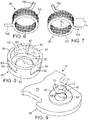
Fig. 6 is a perspective view of one of the torsion springs. -
Fig. 7 is a perspective view of the opposite of the torsion springs. -
Fig. 8 is a perspective a view of one of the bushings. -
Fig. 9 is a perspective view of the tang portion of the blade, illustrating the blade pocket in which a torsion spring resides.
The series ofFigs. 10 through 13 illustrate semi-schematically a sequence of structural steps that occur as the blade rotates from the open to the closed positions. -
Fig. 10 is a side elevational, semi-schematic and cross sectional view illustrating the structures of the auto assist mechanism when the blade is in the fully open and locked position. -
Fig. 11 is a side elevational, semi-schematic and cross sectional view illustrating the structures of the auto assist mechanism when the blade has rotated about 60° from the fully closed position toward the open position. -
Fig. 12 is a side elevational, semi-schematic and cross sectional view illustrating the structures of the auto assist mechanism when the blade has rotated about 40° from the fully closed position toward the open position. -
Fig. 13 is a side elevational, semi-schematic and cross sectional view illustrating the structures of the auto assist mechanism when the blade is in the closed position. -
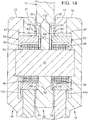
Fig. 14 is a stylized top cross sectional view of the knife ofFig. 1 , taken through the forward portion of the handle and through the blade axis, illustrating the blade in the open position. -
Fig. 15 is a stylized top cross sectional view taken through the same position asFig. 14 , but illustrating the blade in the closed position. -
Figs. 16 through 19 are a series of semi-schematic and semi-cross sectional views illustrating the blade, torsion springs and bushings during a sequence events that occur as the blade is rotated from open to closed. -
Fig. 16 illustrates the structural arrangement of the blade, torsion springs and bushings when the blade is in the open position.Fig. 16 roughly corresponds toFig. 10 . -
Fig. 17 illustrates the structural arrangement of the blade, torsion springs and bushings when the blade is rotated about 120° from the fully open position toward the closed position.Fig. 17 roughly corresponds toFig. 11 . -
Fig. 18 illustrates the structural arrangement of the blade, torsion springs and bushings when the blade is 140° from the fully open position toward the closed position.Fig. 18 roughly corresponds toFig. 12 . -
Fig. 19 illustrates the structural arrangement of the blade, torsion springs and bushings when the blade is in the closed position.Fig. 19 roughly corresponds toFig. 13 . -
Figs. 20 through 25 illustrate a preferred embodiment of an opening assist mechanism according to the present invention. Specifically, -
Fig. 20 is a perspective and partially cut away view of select structures of a knife illustrating an opening assist mechanism according to the present invention, showing the various parts in an exploded view. -
Fig. 21 is a perspective cross sectional view of select structures of the knife shown inFig. 20 , illustrating the blade assembled with one handle sidewall with the blade in the closed position. -
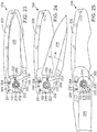
Fig. 22A is a cross sectional view of the opening assist mechanism structures of the knife shown inFig. 20 , with the blade in the fully open position. -
Fig. 22B is a cross sectional view of the knife shown inFig. 22A with the blade rotated to an intermediate position between fully open and fully closed, and with the leg of the spring engaging the blade in a position to drive the blade from closed to open. -
Fig. 22C is a cross sectional view of the knife shown inFigs. 22A and 22B with the blade in the fully closed position. -
Fig. 23 is an elevation view of a knife incorporating the opening assist mechanism shown inFig. 20 , with the near sidewall removed to expose the blade and opening assist mechanism structures and the blade in the closed position. -
Fig. 24 is an elevation view similar toFig. 23 except illustrating the blade at an intermediate position as it is being moved from the open to the closed position. -
Fig. 25 is an elevation view similar toFigs. 22 and23 except showing the blade in the fully open position. - A first illustrated embodiment of a
folding knife 10 incorporating an opening assist mechanism as described inUS 2009/0056146 is illustrated inFigs. 1 through 19 . This embodiment is outside the scope of the claimed invention. Foldingknife 10 includes anelongate handle 12, and ablade 14 that is pivotally attached to the handle at one of its ends-referred to herein as the "forward" end of the handle. Other relative directional terms correspond to this convention: the "rear" or butt end of the handle is opposite the forward end; the "upper" part of the blade is the dull, non-working portion and the "lower" part of the blade is the sharpened, working portion; "inner" or "inward" refers to the structural center of the knife, and so on.Figs. 1 and 2 show theknife 10 with theblade 14 in the open position.Fig. 3 illustrates the blade midway in its rotation from the open to the closed position, and inFig. 4 the blade is shown in the closed position in which the blade, shown partly in dashed lines, is received in a blade-receiving groove defined within thehandle 12 between the sidewalls. An X-Y-Z axis grid is shown inFig. 1 . The X-Y plane is defined as the plane parallel to the plane defined by thehandle 12 and blade 14-the blade travels in the X-Y plane as it is rotated between the closed and open positions. The Z plane is the plane transverse to the X-Y-the blade pivot pin extends longitudinally in the Z-plane. - The
blade 14 of theknife 10 incorporates a blade locking mechanism so that blade may be locked securely in the open position to prevent the inadvertent movement of the blade to its closed position. The blade locking mechanism is described below. - Handle 12 of
knife 10 comprises several components, including a pair of oppositely located side wall sections, generally indicated at 16, 18, that are parallel with each other and held spaced apart from one another byspacers 20, only one of which is shown inFig. 1 . Each of theside wall sections side wall 16 is defined byliner 17 andouter plate 19. Likewise,side wall 18 is defined byliner 21 andouter plate 23. Thespacers 20 are cylindrical sleeves that have a threaded internal bore into which screws 22 are threaded. The screws thus secure the spacers between theliners side walls handle 12 in a secure relationship withside walls Side wall sections Fig. 1 , anoptional pocket clip 17 may be included if desired-the clip is attached to the exterior surface ofside wall 16. - The
blade 14 is pivotally attached to thehandle 12 near the forward end of the handle. The blade used withknife 10 may be of any known type. Theblade 14 shown in the drawings comprises an elongate working portion shown generally at 24 and a tang portion, shown generally at 26. Theblade 14 is pivotally attached thehandle 12 with a blade axis pin (detailed below). Workingportion 24 typically includes asharp edge 30 and ablunt edge 32. Athumb lug 34 may be included onblade 14 to assist with opening and closing the blade. - A
blade receiving groove 36 is defined between the side walls16, 18 by virtue of thespacers 22, described above. Theblade receiving groove 36 defines a slot into which theblade 14 is received when it is moved to its closed position, as shown inFig. 2 . When the blade is in the closed position, thesharp edge 30 of the blade is held safely within the confines of the handle. -
Blade 14 is attached to handle 12 such that the blade's workingportion 24 extends away from thehandle 12 when theblade 14 is in its open position (Fig. 1 ), andtang portion 26 is located within theblade receiving groove 36 between the paired handle side walls when the blade is in either the open or the closed position. That is, thetang portion 26 is always located between theside walls handle 12. The blade is pivotally attached to the handle with blade axis pin, which extends transverse to the plane of the blade and defines a blade pivot shaft. Turning briefly toFig. 5 ,blade axis pin 28 is defined by acylindrical sleeve 44 that extends through abore 40 formed inliner 21, and an aligned bore 42 formed in theliner 17. The sleeve also extends through aligned pivot bore 46 throughtang portion 26 ofblade 14. In the assembledknife 10,cylindrical sleeve 44 is fitted snugly and fixedly through the pivot bore 46 intang 26 ofblade 14 so that the sleeve defines a rotational pivot axis for the blade extending transversely with respect to the plane of the blade and the side walls. Thus,sleeve 44 is axially aligned in the Z-direction-transverse to the X-Y plane. With continuing reference toFig. 5 , one of the ends ofsleeve 44 has alip 45, the outer circumference of which is knurled. The opposite ends of thesleeve 44 are received in circular counter bored recesses 47 in the respective handles, only one of which is shown in the view ofFig. 5 .Washers 50 lie between theblade 14 and theliners sleeve 44 extends through the washers. - A
blade stop pin 48 has its opposite ends anchored in counterbored holes 52 formed inouter plates screws 36 and 54 (only one of the counter boredholes 52 is shown in the view ofFig. 5 ).Screw 38 shown inFig. 5 threads into a threadedopening 39 in liner 17-an identical screw threads into a threadedopening 39 inliner 21. - When the
knife 10 is assembled with the various screws and spacers described above and shown in the drawings, the opposite ends of thecylindrical sleeve 44 are securely captured in the counter bored recesses 47 and the knife is very stable. - As noted previously,
knife 10 incorporates a locking mechanism for locking the blade in the open position. With reference toFig. 5 , the locking mechanism is shown generally withreference number 56 is fully described inU.S. Patent No. 6,574,869 , which is assigned to the assignee of the present invention, and the disclosure of which is incorporated herein by this reference. More specifically, thelocking mechanism 56 used inknife 10 is the same as the locking mechanism described inFigs. 14 through 17 ofUS Patent No. 6,574,869 and described in the specification of that patent. It will be appreciated that not all of the component parts of the locking mechanism are shown or identified with reference numbers in the attached drawings. Nonetheless,blade locking pin 57 is identified; it is a spring-loaded pin that extends through the knife handle with its opposite ends extending through slots in the handles. Thepin 57 locks the blade in the open position by virtue of its contact with a specialized surface of thetang 26. It will further be appreciated that there are many different kinds of locking mechanisms that will work well in connection with the opening assist mechanism described herein, including for example liner locks and lock back mechanisms. - With reference to
Fig. 5 ,knife 10 incorporates anopening assist mechanism 60 that comprises several components. Themechanism 60 will be described generally initially with reference to several drawing figures, and its structure and operation will then be detailed with reference to other drawings. As illustrated inFig. 9 , thetang portion 26 ofblade 14 has acircular recess 62 formed annularly around thebore 46 through whichblade axis pin 28 extends. - The
recess 62 defines an annular depression in the surface of the tang of the blade that may be formed by milling the blade, or during casting of the blade. Thus, therecess 62 has abase surface 64 that is recessed below the level ofsurface 66 of the remainder of thetang 26. Astep 68 forms the outer peripheral edge of thebase shelf 64. A pocket or groove 70 is formed inrecess 62 such that the groove radiates outwardly from the central axis throughbore 46. Thegroove 70 defines a section of a cylinder so that its walls are curved. As detailed below, because the walls of the groove are angled, the spring leg that rides in the groove at some times during rotation of the blade is able to transfer into and out of the groove. An angled or rampedsection 72 extends from one side of thegroove 70 at the edge ofbore 46 and slopes upwardly a short radial distance until the ramped section meets the level ofbase surface 64. For the reasons detailed below, the rampedsection 72 is optional. Finally, thecircular recess 62 includes a scalloped outportion 74 extending from the outermost edge of groove 70 a short radial distance around the circular recess. The edge of the scalloped outportion 74 defines a portion with a larger diameter than the remainder of thecircular recess 62. - Although only one side of
blade 14 is shown inFig. 9 , it is to be understood that the opposite side ofblade 14 includes a circular recess identical in structure to the one described herein, although as detailed below, the structures of the circular recess on the opposite side of the blade are axially rotated relative to the structures illustrated inFig. 9 . - The next structure that is a component of the
opening assist mechanism 60 is illustrated inFig. 8 , and comprises abushing 80.Bushing 80 is a generally cylindrical member 82 that has three flattenedportions cylindrical wall 89 ofbushing 80, defining astop 85 for each flattened portion. As detailed below, the bushing is inserted into a cooperatively shaped circular opening in the liner, which has three flattened portions that correspond to the three flattenedportions bushing 80 defines a first diameter D1 inFig. 8 , and theopening 81 at the "closed"end 83 of the bushing defines a second diameter D2 that is smaller than D1. The innercylindrical wall 89 defines a height L1. Finally, there is afirst notch 90 and asecond notch 92 formed in the innerannular edge 94 ofcylindrical wall 89.Second notch 92 is smaller thanfirst notch 90. The diameter of the interior opening in thewashers 50 is larger than the outer diameter of thebushings 80 so that when the knife is assembled, the bushings extend through the washers, as detailed below. - Turning now to
Figs. 6 and 7 , the two torsion springs 96 and 98 used in theopening assist mechanism 60 are illustrated. Thesprings cylindrical wall 89 ofbushing 80, and a diameter D3, which is slightly less than diameter D1 ofbushing 80.Spring 96 is a left hand spring andspring 98 is a right hand spring. It will be appreciated that there are many different kinds of torsion springs that will suffice for use. The torsion springs 96 and 98 illustrated herein are flattened wire type springs that having coiledbody portions 101 andstraight legs - The assembly of opening assist mechanism will be described with reference to one bushing and one torsion spring. However, as appreciated from the description herein and the drawings of the illustrated embodiment, the opening assist mechanism relies upon a bushing and torsion spring on each side of the blade. Nonetheless, an opening assist mechanism may be built based on the present disclosure that utilizes only one torsion spring. In other words, the opening assist mechanism may be fabricated with only one spring on one lateral side of the blade. While a spring on both sides of the blade is the preferred embodiment, a single spring mechanism is suitable.
- With returning reference to
Fig. 5 ,knife 10 is assembled with torsion springs 96 and 98 received in thecircular recesses 62 on opposite sides ofblade 16 such that theinnermost legs 102 of the springs are received in the recesses. Theoutermost leg 100 of each torsion spring rests innotch 90 inbushing 80.Bushing 80 is inserted throughbore 42liner 17 with the flattenedportions bore 42 until thestops 85 abut the outer wall of the liner. As noted above, the flattened portions of thebushing 80 cooperated with the flattened portions of thebore 42 throughliner 17 to fix the bushing relative to the liner. In other words, bushing 80 cannot rotate.Spring 98 is captured within the interior ofbushing 80, and is retained in the bushing because the diameter D2 ofbushing 80 is less than the diameter D3 of the springs. Thespring 96 andbushing 80 on the opposite lateral side ofblade 14 are assembled withliner 21 in the identical manner. "Outer"leg 100 ofspring 96 is captured innotch 90 in the bushing. Because the bushing cannot rotate andleg 100 of the spring is captured innotch 90, one leg of each spring is fixed relative to thehandle 12.Cylindrical sleeve 44 is inserted through the bushings, the springs, and the blade, and the opposite ends of the sleeve are retained in counter boredportions 47 in the respectiveouter plates handle sidewalls sleeve 44 prevents rotation of the sleeve relative to the handle. It will be appreciated that becausesleeve 44 is inserted axially through the center of the springs, the sleeve acts as a supporting arbor for the springs. - As indicated earlier, the body length L2 of
spring 96 is slightly less than the height L1 ofbushing 80. With the knife fully assembled and the handle halves screwed together, bushing 80, which as noted above is stationary with respect to handle 12, holds theinnermost legs 102 ofsprings grooves 70 on both sides of the blade. The innerannular edge 94 ofbushing 80 lies closely adjacent to thesurface 64. - With returning reference to
Fig. 9 , when theknife 10 is assembledleg 102 ofspring 96 resides ingroove 70, at least at some times during rotation of the blade from closed to open, and from open to closed, as detailed below. The length ofleg 102 is greater than the length of rampedsection 72 of circular recess 62 (as show, for instance, inFig. 10 ). Thus, whenspring 96 is assembled with the other associated components, the end ofleg 102 extends ingroove 70 past the point where rampedsection 72 ends. Whenspring 96 is under rotational torsion-i.e., when the spring is "loaded"-in the X-Y plane, the angular surface ofgroove 70 creates a force vector in the Z plane-i.e., transverse to the plane of the blade-that urges theleg 102 ofspring 96 outwardly, away from the groove incircular recess 62, away from the longitudinally centerline through the blade. In other words, because at all times the surface ofgroove 70 thatleg 102 is being forced against is angled, there is a force in the Z-plane that urges the leg out of the groove toward thebushing 80. Rampedportion 72 provides mechanical relief that allows thespring leg 102 to sit completely down intogroove 70. As noted above and as shown in the drawings, thesprings groove 70 are important so that the spring leg will move into and out of the groove. It will be appreciated that the relative geometries described herein may be modified with the same functional characteristics being achieved. - The
stationary bushing 80 holds theleg 102 in thegroove 70, but as the blade rotates and winds the springs-i.e., loads the springs, thelegs 102 slide along the innerannular edges 94 ofbushings 80 until the inner portion of the legs begin to ride up the angled sides of thegrooves 70. As the rotation continues and thelegs 102 rotate towardnotches 92 there is a force vector applied tolegs 102 in the direction of the Z-plane by the angular edges ofgrooves 70. When thelegs 102 align withnotches 92 inbushings 80, the legs are forced very quickly into the notches. When thelegs 102 are transferred into thenotches 92, the rotational force of the springs is instantly removed from the blade and is transferred to the bushings, which as described above is stationary. - Operation of the
opening assist mechanism 60 will now be described in detail beginning with theblade 14 in the closed position (e.g.,Figs. 4 ,13 and15 ). When in theblade 14 is in the closed position there is no pressure applied to the blade by theopening assist mechanism 60. When the blade is in the closed position, thesprings legs 102 to thestationary bushings 80. Accordingly, no force is applied to the blade by theopening assist mechanism 60 and the blade is retained in the closed position by virtue of the force applied to the tang of the blade by thelocking mechanism 56. This feature of thelocking mechanism 56 is fully described inUS Patent No. 6,574,869 . The force applied toblade 14 bypin 57 is sufficient to retain the blade in the closed position, and the blade will not open even when, for example, the knife is dropped, or subjected to a strong "flick of the wrist" type of motion. Nonetheless, it may be beneficial to include a "safety" mechanism that prevents the blade from opening when the blade is in the closed position. - As stated previously, the diameter of the interior opening in the washer is larger than the outer diameter of the
bushings 80. As best seen inFig. 14 , this results in thebushings 80 extending through the washers in the assembled knife. - It will be appreciated from the foregoing description, from the drawings, and from the more detailed description that follows, that the
bushing 80 as described may be replaced by any number of equivalent structures. As one example, the functional and structural characteristics of the bushing and the way that it interfaces with the torsion spring may be reproduced with a "bushing" that is an integral part of the liner or handle, as opposed to a separate piece. As another example, the handle may be fabricated in a single piece and the bushing may be a part of the unitary handle half. - The drawings of
Figs. 10 through 13 illustrate a sequence that occurs when theblade 14 is moved from the closed position (Fig. 13 ) to the open position (Fig. 10 ). Typically, the blade is rotated by the user applying pressure tothumb lug 34. Asblade 14 is rotated, thecircular recesses 62, which are structural features of thetang 26, rotate. This causes the structures associated withcircular recess 62 to be rotated relative to the fixedbusing 80. This relative rotation between the blade, the bushing, and the spring that is retained in the bushing with one leg fixed thereto results in the functional operation of the opening assist mechanism. - Beginning with
Fig. 13 , as described earlier, theblade 14 is shown retained in this closed position by virtue of the forward pressure ofpin 57 of lockingmechanism 56. Thus,pin 57 is under spring tension that urges the pin in the forward direction illustrated by arrow A. At all times,leg 100 ofspring 98 is captured and led stationary innotch 90 ofbushing 80, andbushing 80 is held stationary by virtue of the flattened portions on the bushing mating with the flattened portions of the bore in theliner 21 through which the bushing extends. InFig. 13 ,spring 98 is wound and thus has significant potential energy. However,leg 102 is innotch 92 and the potential energy of the spring is thus bearing against thestationary bushing 80 and does not apply any rotational pressure to the blade 14 (i.e., in the X-Y plane), although there is force applied to the blade in the Z-plane direction by virtue of the curved edge ofnotch 92. - Turning to the next illustration in the sequence,
Fig. 12 , the blade has begun its rotation toward the open position (arrow B). Here, theleg 102 ofspring 98 remains innotch 92. As a result, the potential energy of the spring has not been released and is still exerted againstbushing 80. Simultaneously, thepin 57 has been urged reawardly, toward the butt end of thehandle 12, as the pin rides over the surface of the tang of the blade. Because the sides ofnotch 92 are curved, theleg 102 is at all times bearing on a curved surface. This is the same mechanical characteristic as described above with respect toleg 102 riding ingroove 70. As a result, because the spring is applying significant pressure against the side of the notch, there is a force in the Z-plane direction that urges the leg in the direction toward the tang of the blade-i.e., out ofnotch 92. This applies some pressure between theleg 102 and the blade in the Z-plane, but this is not rotational pressure that would drive the blade open. - In
Fig. 11 , the blade has rotated in the counterclockwise direction in the drawing so thatleg 102 is just on the threshold of being forced out ofnotch 92 inbushing 80. Whenleg 102 is forced out ofnotch 92 the leg immediately moves into and engagesgroove 70. Since the spring is wound and loaded, movement of the spring leg intogroove 70 results in the immediate transfer of the potential energy from thestationary bushing 80 to therotatable blade 14. The spring thus instantly applies its force as the spring uncoils to the blade to urge the blade rapidly to the open position. - In
Fig. 10 the blade is shown in the open and locked position. In this position an edge on the tang of the blade abutsstop pin 48, which stops the rotation of the blade. The blade is locked by virtue ofpin 57 extending transversely across the upper edge of the tang and being wedged between handle side walls and the blade. It may be seen inFig. 10 that theleg 102 is resting ingroove 70, having rotated in the counterclockwise direction in the drawing away fromnotch 92. Ideally, in this position,spring 98 still exerts pressure on the blade in order to maintain this position. - Attention is now directed to
Fig. 14 , which illustratesknife 10 withblade 14 in the open position, and which is a close up cross sectional view taken through the portion of the handle and blade where the blade attaches to the handle. Withblade 14 in the open position,legs 102 of torsion springs 96 and 98 are resting ingrooves 70 of thecircular recesses 62 formed in both sides oftang 26. The springs are maintained within thegrooves 70 by the innerannular edge 94 ofbushing 80. Thesprings stop pin 48. The fixedlegs 100 of both springs are seen captured innotches 90 ofbushing 80, andnotches 92 are of course not occupied. Because the springs continue to apply pressure to the blade when the blade is in the open position, the lock mechanism is assured of positive locking. This may be contrasted with many opening assist mechanisms, which drive the blade to open but do not apply pressure to the blade after a certain point in the blade's rotation. This results in the possibility of failure to lock. -
Fig. 15 is similar toFig. 14 except it showsknife 10 withblade 14 in the closed position. Here, thesprings legs 102 have been forced out of contact withblade 14 and thus reside innotches 92 where they apply their potential energy against thestationary bushing 80. - It will be appreciated that when the blade is in the open position the locking mechanism may be unlocked and the blade may be rotated to the closed position. The sequence of events that occur as the blade moves from open to closed is shown by the series of drawings of
Fig. 10 through Fig. 13 . Beginning withFig. 10 , the blade is unlocked by moving the pin of lockingmechanism 56 rearwardly toward the butt end of the knife so that the pin disengages from the tang of the blade. The blade is then rotated in the clockwise direction inFig. 10 (i.e., opposite the direction of arrow B). As this happens, theleg 102 is pushed by the edge ofgroove 70, thereby windingspring 98. - As rotation of the blade continues in the clockwise direction, the spring continues to be wound, or loaded, imparting greater potential energy to the spring. In
Fig. 11 theleg 102 is still ingroove 70, but the position of theleg 102 is approaching the point where the leg aligns withnotch 92. InFig. 12 theleg 102 has aligned withnotch 92 and theleg 102 is forced fromgroove 70 intonotch 92, thereby transferring the spring pressure from the blade to the bushing. The primarystructure causing leg 102 to be forced from thegroove 70 intonotch 92 is the sloped sides of thegroove 70, which tend to "lift" the leg in the Z-plane, towardnotch 92. The rampedportion 72 contributes additional "lifting" action that forces the leg in the Z-plane and intonotch 92, but as noted above, the primary function of rampedportion 72 is to allowleg 102 to rest completely in thegroove 70. - In
Fig. 13 leg 102 may be seen innotch 92. As a result, the blade rotates freely into the closed position. And as noted above, the spring pressure applied to lockingmechanism 56 urges the pin of the mechanism forward, retaining the blade in the closed position. - Attention is now directed to the series of drawings of
Figs. 16 through 19 , which comprise a sequential series of semi-schematic illustrations showing the structure and functional attributes of the opening assist mechanism. In this series of drawings the only components that are shown are thebushings 80, thelegs 102 ofsprings blade 14. These drawings are semi-schematic because they omit for clarity certain structures that would normally be seen in these views. Moreover, as noted above, the structures in thecircular recesses 62 on each side of the blade are axially rotated relative to one another. In other words, groove 70 on one side of the blade is not in the same position asgroove 70 on the opposite side of the blade. The primary reason for this relative rotation of the structures is to maintain the strength and integrity of the blade. But as such, not all of the structures shown inFigs. 16 through 19 would actually be seen if these cross sectional views were structurally accurate. However, they are presented here in the manner shown in order to facilitate a detailed explanation of the mechanism and how it operates. - Beginning with
Fig. 16 ,blade 14 is in the open position.Legs 102 of both torsion springs (96 and 98) are retained ingrooves 70 because the innerannular edges 94 of thebushings 80 are held closely abutting the surface of thetang 26 of the blade. The springs are slightly loaded, and the direction of the force that the springs apply to the blade is shown with arrows A. Arrow B represents the vector direction in which force is applied toblade 14 to move it from the open position toward the closed position. In this blade-open position,notches 92 are unoccupied. - In
Fig. 17 the blade has begun its rotation from the open position toward the closed position. As this occurs, thesprings Figs. 10 through 13 ), thelegs 102 are carried and pushed by thegrooves 70 to wind the springs.Notches 92 are still unoccupied, but the position of the notches is approaching the position of thelegs 102. - In the next sequential drawing of
Fig. 18 , as rotation ofblade 14 continues in the direction represented by arrow B,notches 92 have now rotated to the point where the notches begin to align with thelegs 102 of the springs, and thelegs 102 are simultaneously being "lifted" in the direction of the Z-axis by the curved sides of grooves 70-represented by arrows C. Once thelegs 102 are able to be received innotches 92 they are pushed into the notches by the curved sides ofgrooves 70 and the spring force (arrows A) is immediately transferred from theblade 14 to thebushing 80. The blade is at this point under no spring force applied by the opening assist mechanism and is thus freely rotatable to the closed position. When a locking mechanism such as that described above is used with the knife, thetransverse pin 57 at this point urges the blade to continue toward the closed position. - In the final drawing of this sequence,
Fig. 19 , theblade 14 is in the closed position and there is no spring force being applied to the blade by thesprings bushing 80. Thelegs 102 are in this position resting in the scalloped outportions 74 of the circular recesses 62. - From the foregoing description it will be appreciated that the opening assist mechanism described with reference to
Figs. 1 through 19 may be applied to a multitude of other equivalent mechanical constructs. As noted above, it will be appreciated that bushing 80 may be eliminated and replaced by any structure and method for connecting the torsion spring to the liner or handle.Bushing 80 may in this sense be seen as an optional structure that could be replaced by any equivalent structure for performing the function. There are many structural equivalents that can perform the function. As one example, the structure defined by the bushing could be formed as an integral part of the liner or handle rather than as a separate structure as described above in the preferred embodiment. Further, the bushing could be replaced by a recess formed in the liner that serves to contain the spring, fix one spring leg, and defines a notch into which the other spring leg may reside to remove spring pressure from the blade and transfer the spring pressure to the liner. With this as context, the word "bushing" as used herein is not limited to a structure that is separate from the liner or handle, but instead should be read to encompass any structure that facilitates the function ascribed to the bushing herein. - A second illustrated embodiment of a
folding knife 200 incorporating an opening assist mechanism according to the present invention is illustrated inFigs. 20 through 25 . Only select structural parts offolding knife 200 are illustrated in order to describe the knife opening assist mechanism, referenced generally withreference number 202; those of skill in the art will readily understand that the description ofknife 10 above otherwise applies fully toknife 200. InFigs. 20 through 25 ,knife 200 includes anelongate handle 204, and ablade 206 that is pivotally attached to the handle at the forward end of the handle. Thehandle 204 comprises opposedsidewalls 208 and 210 (Figs. 22A, 22B and 22C ). -
Only sidewall 208 is shown inFig. 20 in order to illustrate the components ofopening assist mechanism 202. Theinner surface 212 ofhandle sidewall 208 includes a first recessedportion 214 that is associated with springs and other component parts (not shown) that are utilized a blade locking mechanism that is not the subject of the present invention. Immediately forward of the first recessedportion 214 is acylindrical recess 216 that defines a seat for receiving thebushing 218, which as detailed below, retains aspring 220.Cylindrical recess 216 includes a cylindricalinner stud 222 that has a threadedinterior bore 224, the central axis of which defines the axis of the pivot shaft about whichblade 206 pivots as it moves between the open and closed positions. As detailed below, apivot screw 226 has a threadeddistal end 228. In the assembled knife,bushing 218 andpivot screw 226 extend through the pivot axis bore 230 inblade 206 with the threadeddistal end 228 of the pivot screw is threaded intointerior bore 224 to retainbushing 218 in place; as noted below, neither the pivot screw nor the bushing retain theblade 206 in place in the handle, other than the fact that the bushing extends through the pivot axis bore in the blade.Cylindrical recess 216 includes agroove 232 that radiates outwardly from the axis throughbore 226 and which is configured to receive a leg ofspring 220. Aremovable stop pin 231 is located immediately aboverecess 216. -
Spring 220 is a torsion spring similar to thesprings spring 220 has a body length L2 and a diameter D3 (the dimensions L2 and D3 are not shown inFig. 20 but correspond to the same dimensions shown for L2 and D3 inFig. 7 ). Spring 220-is a flattened wire type of spring as described above and hasstraight legs - With continuing reference to the exploded view of
Fig. 20 ,bushing 218 is a housing with a cylindrical housing body sidewall and having on one end a recessedannular shelf 234 and a centralaxial bore 236 opening through the annular shelf into the interior of the housing. The interior of thebushing 218 is open to receive and retain thespring 220. The end ofbushing 218 that in the assembled knife abutshandle sidewall 208 includes atab 238 that is received into a cooperatively shaped notch (not shown) inrecess 216. It will be appreciated that when the bushing is fully inserted into therecess 216 withtab 238 received in the notch, the bushing is fixed and cannot rotate relative to the handle. The diameter ofbushing 218 is just slightly smaller than the diameter of pivot axis bore 230 throughblade 206 and the diameter ofrecess 216 so that the bushing may be inserted through the blade and received into the recess during assembly, with close tolerances therebetween. - A partial
annular groove 240 is formed in the sidewall ofbushing 218 about mid-way along the length of the bushing housing and extending completely through the sidewall into the open interior of the bushing. The groove is referred to herein at times as a "partial annular groove" because as seen inFigs. 20 and23 through 25 , the groove extends only partly around the circumference of the cylindrical bushing, preferably between about 180 to 225 degrees. The width of the groove is preferably the same along the length thereof, except at one end of the groove agroove extension 246 opens in a direction transverse to the groove to define a widened portion. With specific reference toFig. 20 , it may be seen that the sidewall ofgroove extension 246 is sloped - this sloped sidewall is referred to as slopedsidewall 242. - As noted, the distal end of
pivot screw 226 is threaded. The pivot screw has a flatteneddisk 244 at the proximal end, and acentral portion 247 between the proximal and distal ends. -
Blade 206 includes aradial groove 250, also referred to herein as a notch that extends outwardly away from the axis throughbore 230 and which is configured to receiveleg 100 ofspring 220 at some times during rotation of the blade from open to closed, closed to open, as detailed below. Both of the side walls of thenotch 250 on whichleg 100 are sloped; specifically, as best seen inFigs. 20 and 21 , thefirst side wall 251 and the oppositesecond side wall 252 ofnotch 250 slope upwardly from the lower surface orfloor 254 of the notch. The purpose and function of thesloping side wall 252 is described below. With reference to the specific view ofFig. 21 , thefirst side wall 251 ofnotch 250 is on the right hand side of the notch - thesecond side wall 252 is on the left hand side of the notch. - With
stop pin 231 removed fromhandle sidewall 208,knife 200 is assembled withblade 206 andopening assist mechanism 202 by first insertingbushing 218 partially throughbore 230 in the blade and then insertingspring 220 into the open interior of the bushing withleg 100 extending through partialannular groove 240 and such that theleg 100 is received innotch 250 in the blade. Theblade 206,bushing 218 andspring 220 are then aligned with and mated to handlesidewall 208 with the blade oriented about 90 degrees beyond the normal stop position (i.e., with the blade pointing upwardly relative to the handle). In this position,leg 102 ofspring 220 is inserted innotch 232 and the spring is in a relaxed condition. The blade is then rotated toward the closed position and stoppin 231 is screwed intohandle sidewall 208; this winds the spring so that the spring is under constant spring tension at all times in the assembled knife.Bushing 218 is rotated relative to the handle so thattab 238 is received in the cooperative notch inrecess 216. It will be appreciated that withleg 102 ofspring 220 innotch 232, theleg 102 is fixed relative to thehandle sidewall 208, and the bushing is fixed relative to the handle by virtue of thetab 238 being received in the notch. As an alternate arrangement, theleg 102 could be fixed to a notch of thebushing 218 instead of the handle itself; theleg 102 is fixed relative to the handle. Either way, at thispoint pivot screw 226 is inserted throughbore 236 inbushing 218 and thedistal end 228 is threaded into threadedbore 224. The flatteneddisk 244 at the proximal end of the pivot screw is received in theannular shelf 234 as the pivot screw is tightened. When thebushing 218 is tightened, partialannular groove 240 is positioned just below the plane defined by theouter surface 260 oftang portion 262 ofblade 206. However,notch 250 in the blade is recessed intang portion 262 relative to the plane ofouter surface 260, and notch as best shown inFig. 21 ,notch 250 opens to and communicates with the partialannular groove 240 inbushing 218. Thus, asblade 206 rotates from closed to open, and vice versa, notch 250 is open to partialannular groove 240 through the entire rotation. Moreover, as also best seen inFig. 21 ,groove extension 246 extends to a level above the plane ofouter surface 260 of the blade. As such,leg 100 ofspring 220 is able to rise out ofnotch 250 in the blade and rest onouter surface 260 of the blade, as illustrated, when the blade is near and in the closed position. - It will be appreciated from examination of
Figs. 20 and 21 that at this stage of the assembly,blade 206 is retained in position relative to handlesidewall 208 only by virtue ofleg 100 ofspring 220 extending over theouter surface 260 of thetang portion 262 of the blade, for example, intonotch 250 or as shown inFig. 21 , resting onouter surface 260. In other words, while bushing 218 is attached to handlesidewall 208 withpivot screw 226, theblade 206 is not directly attached to the handle or to the pivot screw. Instead, the blade is held in place only by virtue of the interaction ofleg 100 ofspring 220 as just described. The manufacturing tolerances between the various structural components are quite small, as is typical in the industry. As such, even without thesecond sidewall 210 assembled there is very little wobble between the blade and thesidewall 208 as the blade is rotated. As detailed below, this structural relationship between the blade and the handle provides significant assembly advantages. - With the
blade 206 assembled withhandle sidewall 208, the blade is moved into the closed position and stoppin 231 is installed in the sidewall as shown inFig. 21 . Since the blade is retained in this position, the opening assist mechanism is fully operational with only onesidewall 208 ofhandle 204 assembled with the blade. - Operation of the
opening assist mechanism 202 will now be described with reference to the series ofFigs. 22A, 22B, 22C andFigs. 23, 24 and 25 , beginning withblade 206 in the open position shown inFigs. 22A and25 . It will first be noted that inFigs. 22A, 22B and 22C thesecond sidewall 210 is attached tofirst sidewall 208 with a number of screws (not shown) that extend from one sidewall to the other along the spline of the knife, and also ascrew 263 that is inserted through thesidewall 210 and threads into the proximal end ofpivot screw 226. With reference now toFig. 25 , with the blade in the open position ashoulder 266 on thetang portion 262 ofblade 206 abutsstop pin 231 so that the blade is prevented from rotating past the open stop position (ofFig. 25 ). As detailed below, in the open stop position thespring 220 is "loaded" and pushing against the blade so that the blade is held in the open stop position. (Also in this position, ablade lock pin 264 engages the blade to prevent its unintended movement from the open stop position toward the closed position. The locking mechanism shown in the drawings, includingblade lock pin 264, are not a part of the present invention.) In this open stop position,leg 100 ofspring 220 is retained in partialannular groove 240 ofbushing 218 and extends intonotch 250 ofblade 206, and because thespring 220 is wound, theleg 100 is pushing with spring force againstside wall 252 of notch 205. This spring force applied against the blade maintains the blade in the open (and locked, stopped) position. As noted previously, the partialannular groove 240 is below the plane defined bysurface 260 ofblade 206, except at thegroove extension 246. Thus, the groove is at the same level asnotch 250 as the blade rotates. Stated another way, the groove is open to and communicates with thenotch 250 along the entire length of the groove. However, at theextended groove portion 246 thegroove 240 is open to both notch 250 and theouter surface 260 of the tang. This is best shown inFig. 22A . As such, in the open position ofFigs. 22A and25 (and at all blade positions except the closed position, described below), theleg 100 is retained innotch 250 by partialannular groove 240. Althoughside wall 252 is sloped,leg 100 cannot ride up the slope because the leg is bounded and retained in the partialannular groove 240. It will be appreciated that as described above, the leg applies spring force to the blade along the plane of blade rotation at all times whenleg 100 is ingroove 240, except when the blade is closed or near closed andleg 100 is resting onouter surface 260. When theleg 100 is onouter surface 260, the leg applies spring force to the blade in a direction transverse to the plane of blade rotation. -
Blade 206 is moved from the open, stopped and locked position ofFig. 25 by first unlocking any locking mechanism that may be in use (for example, with reference toFig. 24 , lockingpin 264 is slid toward the rear end of the knife handle so that the tang of the blade clears the lock pin as the blade is rotated). Arrow A inFig. 24 shows the direction of rotation of the blade as it moves from open toward closed. As the blade is rotated,leg 100 ofspring 220 remains in partialannular groove 240 with the leg pushing againstside wall 252 ofnotch 250 in the blade. Again, the spring is wound so that it is providing resistance to rotation of the blade as it rotates in the direction of arrow A. In addition, rotation of the blade in this direction further winds and loads the spring and thus increases the spring force applied by the spring to the blade. Because partialannular groove 240 is beneath the plane defined bysurface 260 ofblade 206, theleg 100 remains in partialannular groove 240 and notch 250 at all times during this phase of the rotation. As rotation ofblade 206 continues from open to closed, notch 250 of the blade andleg 100 of the spring, which are rotating together, eventually align withgroove extension 246 in thebushing 218. As the blade rotation approaches the closed position (starting withFig. 22B and moving toFig. 22C , andFig. 23 ),leg 100 enters the point in partialannular groove 240 such that theleg 100 may move upwardly, along slopedside wall 252 and away from the body of the spring and into groove extension 246 - that is, the leg slides on the slopedsidewall 250 and then up the now-alignedsloped sidewall 242 ofgroove extension 246. As theleg 100 moves in this direction and as rotation of the blade continues, the leg is pushed up the sloped surface ofside wall 252 ofnotch 250, entersgroove extension 246. Once the leg has risen a sufficient distance intogroove extension 246 the leg slides ontosurface 260 of the blade, as shown inFig. 21 , under the force of the spring, which is driving the leg at all times toward the open position.Leg 100 cannot rotate further toward the open direction beyond the position shown inFig. 21 because the leg is bounded bygroove extension 246 ofbushing 218, which as noted previously is fixed tosidewall 208 and cannot rotate. - The normal, or "resting" position of
leg 100 relative to partialannular groove 240 is the position where the leg is in held in the groove. Thus, the resting position of thespring 220 is shown inFig. 20 with all of the coils of the spring that make up the body held relatively tightly against one another. As such, when the leg is atopsurface 260 as shown inFig. 21 , the coils of the spring are separated slightly from one another as theleg 100 is moved out of the resting position. As such, there is a downward force applied by the leg to the surface of the blade - theleg 100 is normally urged toward its resting position - transverse to the plane of blade rotation. However, once the leg assumes this position onsurface 260, all rotational spring force applied to the blade by the spring stops because as noted the leg is bounded bygroove extension 246, so all rotational spring force is applied tobushing 218. As noted, there is pressure applied byleg 100 to the blade; this force helps the blade to normally remain in the closed position until it is intentionally moved toward the open position, as detailed below. When a locking mechanism such as that associated withlock pin 264 is used, the locking pin (which is driven forward in the illustration ofFig. 23 with springs, not shown) further retains the blade in the closed position.Blade 206 is moved to the open position from the closed position by rotating the blade in the direction opposite arrow A inFig. 24 . As the blade is rotated,leg 100 slides on thesurface 260 of thetang 262 of the blade until thenotch 250 aligns withleg 100. Once thenotch 250 aligns withleg 100, the leg assumes its normal "resting" position relative to the partialannular groove 240 and thus moves downwardly alongsloped sidewall 252 and into thenotch 250. As this occurs,leg 100 aligns with and enters the partialannular groove 240 and is free to "unwind." Thus, theleg 100 pushes againstside wall 252 ofnotch 250 and because the leg has entered the partial annular groove and is bounded therein, the spring drives the blade quickly under spring force into the open, stopped and locked position. - As noted previously, the structural components that define the
opening assist mechanism 202 allow theblade 206 to be attached to the handle and assembled with the opening assist mechanism with only one of the twosidewalls Fig. 21 , the opening assist mechanism is fully functional even though the blade is held in place only by theleg 100 ofspring 202. This provides significant manufacturing and assembly economies. Specifically, the opening assist mechanism and lockup position may be adjusted during assembly prior to both handle sidewalls being secured in place. For instance, the stop pin described inU.S. Patent No. 7,278,213 , which is owned by the assignee of the present invention, allows quick adjustment of the lockup position of a blade. When a stop pin such as that described in the '213 patent is used in a knife such as that shown inFig. 20 with theopening assist mechanism 202, technicians are able to very quickly adjust the knife operation and lockup during assembly. Moreover, because the blade is held in place with only one of the two sidewalls attached, assembly of the entire knife is much more efficient because the degree of manual dexterity required to assemble all of the various pieces is significantly reduced. In addition, as shown in the series ofFigs. 22A, 22B and 22C , thescrew 263 is exposed to the outside of the knife. This allows a user to adjust the amount of blade wobble without affecting the operation of theopening assist mechanism 202. Thus, because theleg 100 retainsblade 206 in place even whensidewall 210 is removed, a user may completely removescrew 236 without causing the opening assist mechanism to come apart. Many users desire to "customize" their knives by changing the rate at which the blade opens, or varying the wobble between the blade and the handle. The opening assist mechanism described above allows this type of user-customization without the danger of disassembly of a complicated opening assist mechanism.
Claims (11)
- A folding knife (200), comprising,
a handle (204) defined by first and second spaced apart handle halves (208, 210);
a blade (206) rotationally connected between the handle halves, said blade having a cylindrical pivot bore (230) through a tang of the blade and said tang defining a tang surface (260) around the pivot bore, the blade having a radial groove (250) in the tang surface and the blade movable along a rotational path from a closed position to an open position,
a bushing (218) extending through the pivot bore (230) and fixed relative to said first handle half (208), said bushing having a cylindrical body, an open interior (236) and an annular groove (240) extending around a portion of the cylindrical body and opening through the body into the open interior of the bushing;
a spring (220) in the bushing, said spring having a first leg (100) and a second leg (102), the second leg fixed relative to the handle (204) characterized in that the first leg (100) extends through the annular groove (240) such that the first leg extends into the radial groove (250) in the tang of the blade during one portion of the rotational path and does not extend into the radial groove (250) in the tang of the blade during another portion of the rotational path. - The folding knife according to claim 1 wherein said annular groove (240) has a first end and a second end, and wherein the second end defines an extended notch portion (246).
- The folding knife according to claim 2 wherein said annular groove (240) has a first width along a length thereof, and the width at the extended notch portion (246) is greater than the first width.
- The folding knife according to claim 3 wherein said tang surface (260) defines a plane and said annular groove (240) is positioned below the plane.
- The folding knife according to claim 4 wherein said annular groove (240) is aligned with said radial groove (250) in the tang of the blade so that said annular groove (240) communicates with said radial groove (250).
- The folding knife according to claim 5 wherein said annular groove (240) communicates with said radial groove (250) throughout the entire rotational path of the blade from the closed position to the open position.
- The folding knife according to claim 4 wherein the annular groove (240) at the extended notch portion (246) is above the plane defined by the tang surface (260).
- The folding knife according to claim 1 wherein the first leg (100) is positioned on the tang surface (260) when the blade is in the closed position.
- The folding knife according to claim 8 wherein the rotational path defines a blade rotation plane and when said first leg (100) is positioned on the tang surface (260) the first leg applies spring force to the blade (206) in a direction transverse to the blade rotation plane.
- The folding knife according to claim 1 wherein the rotational path defines a blade rotation plane and when said first leg (100) extends into the radial groove (250) in the tang of the blade during a portion of the rotational path said first leg (100) applies spring force to the blade (206) in a direction substantially parallel to the blade rotational plane.
- The folding knife according to claim 1 wherein the radial groove (250) has a floor (254) surface and opposed sidewalls (252), and wherein at least one of said opposed sidewalls is sloped relative to said floor surface.
Applications Claiming Priority (2)
| Application Number | Priority Date | Filing Date | Title |
|---|---|---|---|
| US13/004,178 US8375590B2 (en) | 2007-09-05 | 2011-01-11 | Knife blade opening mechanism |
| PCT/US2011/064793 WO2012096748A1 (en) | 2011-01-11 | 2011-12-14 | Knife blade opening mechanism |
Publications (3)
| Publication Number | Publication Date |
|---|---|
| EP2663430A1 EP2663430A1 (en) | 2013-11-20 |
| EP2663430A4 EP2663430A4 (en) | 2014-06-25 |
| EP2663430B1 true EP2663430B1 (en) | 2017-01-18 |
Family
ID=46507384
Family Applications (1)
| Application Number | Title | Priority Date | Filing Date |
|---|---|---|---|
| EP11855772.7A Active EP2663430B1 (en) | 2011-01-11 | 2011-12-14 | Knife blade opening mechanism |
Country Status (4)
| Country | Link |
|---|---|
| EP (1) | EP2663430B1 (en) |
| CN (1) | CN103298589B (en) |
| TW (2) | TWI517953B (en) |
| WO (1) | WO2012096748A1 (en) |
Cited By (1)
| Publication number | Priority date | Publication date | Assignee | Title |
|---|---|---|---|---|
| US9592612B2 (en) | 2012-05-17 | 2017-03-14 | Spyderco, Inc. | Split spring locking feature for a folding tool |
Families Citing this family (10)
| Publication number | Priority date | Publication date | Assignee | Title |
|---|---|---|---|---|
| US9492916B2 (en) | 2012-04-30 | 2016-11-15 | Spyderco, Inc. | Locking mechanism for a push button activated folding tool |
| EP2895306B1 (en) * | 2012-09-09 | 2018-10-17 | Benchmade Knife Co., Inc. | Folding knife with dual operational modes |
| WO2014039254A1 (en) * | 2012-09-09 | 2014-03-13 | Mentor Group, L.L.C. | Folding knife with dual operational modes |
| EP2958713B1 (en) * | 2013-02-20 | 2019-05-08 | Benchmade Knife Co., Inc. | Folding knife with dual operational modes |
| US9943970B2 (en) | 2014-11-14 | 2018-04-17 | Spyderco, Inc. | Rotational wedge locking mechanism for a folding knife |
| JP6582743B2 (en) * | 2015-08-27 | 2019-10-02 | 三星ダイヤモンド工業株式会社 | Cutting tools and cutlery |
| CN113165193B (en) | 2018-12-13 | 2022-09-09 | 蝴蝶刀具公司 | Latchless locking mechanism for butterfly knives |
| EP3960401A4 (en) * | 2019-04-22 | 2023-02-22 | Ponomarev, Igor Vladimirovich | FOLDING KNIVES (VARIANTS) |
| JP6697624B1 (en) | 2019-11-12 | 2020-05-20 | 純平 間狩 | Folding knife |
| CN112807039A (en) * | 2021-03-05 | 2021-05-18 | 陈鸿强 | Endoscope thyroid surgery retractor |
Family Cites Families (12)
| Publication number | Priority date | Publication date | Assignee | Title |
|---|---|---|---|---|
| US5029354A (en) * | 1990-08-24 | 1991-07-09 | F. Boyd, Ltd. | Knife |
| US5737841A (en) | 1996-07-12 | 1998-04-14 | Mchenry; William J. | Pocket knife with lock |
| US5819414A (en) * | 1997-12-19 | 1998-10-13 | Marifone; Anthony L. | Double action folding knife |
| FR2793182A3 (en) * | 1999-05-05 | 2000-11-10 | Yves Neveux | Switch blade speed regulator for knife or saw has spring tensioned or relaxed by rotating plastic knob on handle |
| FR2836854A1 (en) * | 2002-03-07 | 2003-09-12 | Bastide Sarl | Knife with folding spring-loaded blade has pivot pin surrounded by hollow bush containing blade |
| US6701621B2 (en) * | 2002-05-08 | 2004-03-09 | Charles L. Kain | Releasable double locking knife |
| US7278213B2 (en) | 2004-04-07 | 2007-10-09 | Mentor Group, L.L.C. | Hand tool stop pin |
| CN2710925Y (en) * | 2004-06-08 | 2005-07-20 | 顺德工业股份有限公司 | utility knife |
| US7051441B2 (en) * | 2004-09-17 | 2006-05-30 | United Cutlery Corporation | Leaf spring assisted opener |
| US8375589B2 (en) * | 2007-02-14 | 2013-02-19 | Gbii Corporation | Folding knife |
| US8164009B2 (en) * | 2007-04-13 | 2012-04-24 | Autonetworks Technologies, Ltd. | Control knob which operates multiple systems |
| US7748122B2 (en) * | 2007-09-05 | 2010-07-06 | Mentor Group, L.L.C. | Knife blade opening mechanism |
-
2011
- 2011-12-14 EP EP11855772.7A patent/EP2663430B1/en active Active
- 2011-12-14 WO PCT/US2011/064793 patent/WO2012096748A1/en not_active Ceased
- 2011-12-14 CN CN201180064779.8A patent/CN103298589B/en active Active
- 2011-12-21 TW TW104106697A patent/TWI517953B/en active
- 2011-12-21 TW TW100147706A patent/TWI480144B/en active
Non-Patent Citations (1)
| Title |
|---|
| None * |
Cited By (1)
| Publication number | Priority date | Publication date | Assignee | Title |
|---|---|---|---|---|
| US9592612B2 (en) | 2012-05-17 | 2017-03-14 | Spyderco, Inc. | Split spring locking feature for a folding tool |
Also Published As
| Publication number | Publication date |
|---|---|
| CN103298589B (en) | 2016-06-01 |
| TWI517953B (en) | 2016-01-21 |
| CN103298589A (en) | 2013-09-11 |
| TWI480144B (en) | 2015-04-11 |
| EP2663430A4 (en) | 2014-06-25 |
| WO2012096748A1 (en) | 2012-07-19 |
| EP2663430A1 (en) | 2013-11-20 |
| TW201236834A (en) | 2012-09-16 |
| TW201521980A (en) | 2015-06-16 |
Similar Documents
| Publication | Publication Date | Title |
|---|---|---|
| US8375590B2 (en) | Knife blade opening mechanism | |
| EP2183080B1 (en) | Knife blade opening mechanism | |
| WO2012096748A1 (en) | Knife blade opening mechanism | |
| US7293360B2 (en) | Knife blade opening mechanism | |
| US9505141B2 (en) | Folding knife with dual operational modes | |
| EP2895306B1 (en) | Folding knife with dual operational modes | |
| US8646184B2 (en) | Dual taper release button for folding knife | |
| US11951641B2 (en) | Easily disassembled folding knife | |
| US20110162211A1 (en) | Adjustable Diameter Pivot Shaft for a Hand Tool | |
| CN111051018A (en) | Dual blade locking mechanism | |
| WO2009136987A1 (en) | Release button for folding knife | |
| HK1139103B (en) | Knife blade opening mechanism |
Legal Events
| Date | Code | Title | Description |
|---|---|---|---|
| PUAI | Public reference made under article 153(3) epc to a published international application that has entered the european phase |
Free format text: ORIGINAL CODE: 0009012 |
|
| 17P | Request for examination filed |
Effective date: 20130523 |
|
| AK | Designated contracting states |
Kind code of ref document: A1 Designated state(s): AL AT BE BG CH CY CZ DE DK EE ES FI FR GB GR HR HU IE IS IT LI LT LU LV MC MK MT NL NO PL PT RO RS SE SI SK SM TR |
|
| DAX | Request for extension of the european patent (deleted) | ||
| REG | Reference to a national code |
Ref country code: DE Ref legal event code: R079 Ref document number: 602011034565 Country of ref document: DE Free format text: PREVIOUS MAIN CLASS: B26B0003060000 Ipc: B26B0001040000 |
|
| A4 | Supplementary search report drawn up and despatched |
Effective date: 20140523 |
|
| RIC1 | Information provided on ipc code assigned before grant |
Ipc: B26B 1/04 20060101AFI20140519BHEP |
|
| 17Q | First examination report despatched |
Effective date: 20151109 |
|
| GRAP | Despatch of communication of intention to grant a patent |
Free format text: ORIGINAL CODE: EPIDOSNIGR1 |
|
| INTG | Intention to grant announced |
Effective date: 20160628 |
|
| GRAS | Grant fee paid |
Free format text: ORIGINAL CODE: EPIDOSNIGR3 |
|
| RAP1 | Party data changed (applicant data changed or rights of an application transferred) |
Owner name: BENCHMADE KNIFE CO., INC. |
|
| GRAA | (expected) grant |
Free format text: ORIGINAL CODE: 0009210 |
|
| AK | Designated contracting states |
Kind code of ref document: B1 Designated state(s): AL AT BE BG CH CY CZ DE DK EE ES FI FR GB GR HR HU IE IS IT LI LT LU LV MC MK MT NL NO PL PT RO RS SE SI SK SM TR |
|
| REG | Reference to a national code |
Ref country code: GB Ref legal event code: FG4D |
|
| REG | Reference to a national code |
Ref country code: CH Ref legal event code: EP |
|
| REG | Reference to a national code |
Ref country code: AT Ref legal event code: REF Ref document number: 862637 Country of ref document: AT Kind code of ref document: T Effective date: 20170215 |
|
| REG | Reference to a national code |
Ref country code: IE Ref legal event code: FG4D |
|
| REG | Reference to a national code |
Ref country code: DE Ref legal event code: R096 Ref document number: 602011034565 Country of ref document: DE |
|
| REG | Reference to a national code |
Ref country code: NL Ref legal event code: MP Effective date: 20170118 |
|
| REG | Reference to a national code |
Ref country code: LT Ref legal event code: MG4D |
|
| REG | Reference to a national code |
Ref country code: AT Ref legal event code: MK05 Ref document number: 862637 Country of ref document: AT Kind code of ref document: T Effective date: 20170118 |
|
| PG25 | Lapsed in a contracting state [announced via postgrant information from national office to epo] |
Ref country code: NL Free format text: LAPSE BECAUSE OF FAILURE TO SUBMIT A TRANSLATION OF THE DESCRIPTION OR TO PAY THE FEE WITHIN THE PRESCRIBED TIME-LIMIT Effective date: 20170118 |
|
| PG25 | Lapsed in a contracting state [announced via postgrant information from national office to epo] |
Ref country code: FI Free format text: LAPSE BECAUSE OF FAILURE TO SUBMIT A TRANSLATION OF THE DESCRIPTION OR TO PAY THE FEE WITHIN THE PRESCRIBED TIME-LIMIT Effective date: 20170118 Ref country code: LT Free format text: LAPSE BECAUSE OF FAILURE TO SUBMIT A TRANSLATION OF THE DESCRIPTION OR TO PAY THE FEE WITHIN THE PRESCRIBED TIME-LIMIT Effective date: 20170118 Ref country code: HR Free format text: LAPSE BECAUSE OF FAILURE TO SUBMIT A TRANSLATION OF THE DESCRIPTION OR TO PAY THE FEE WITHIN THE PRESCRIBED TIME-LIMIT Effective date: 20170118 Ref country code: GR Free format text: LAPSE BECAUSE OF FAILURE TO SUBMIT A TRANSLATION OF THE DESCRIPTION OR TO PAY THE FEE WITHIN THE PRESCRIBED TIME-LIMIT Effective date: 20170419 Ref country code: IS Free format text: LAPSE BECAUSE OF FAILURE TO SUBMIT A TRANSLATION OF THE DESCRIPTION OR TO PAY THE FEE WITHIN THE PRESCRIBED TIME-LIMIT Effective date: 20170518 Ref country code: NO Free format text: LAPSE BECAUSE OF FAILURE TO SUBMIT A TRANSLATION OF THE DESCRIPTION OR TO PAY THE FEE WITHIN THE PRESCRIBED TIME-LIMIT Effective date: 20170418 |
|
| PG25 | Lapsed in a contracting state [announced via postgrant information from national office to epo] |
Ref country code: PL Free format text: LAPSE BECAUSE OF FAILURE TO SUBMIT A TRANSLATION OF THE DESCRIPTION OR TO PAY THE FEE WITHIN THE PRESCRIBED TIME-LIMIT Effective date: 20170118 Ref country code: LV Free format text: LAPSE BECAUSE OF FAILURE TO SUBMIT A TRANSLATION OF THE DESCRIPTION OR TO PAY THE FEE WITHIN THE PRESCRIBED TIME-LIMIT Effective date: 20170118 Ref country code: AT Free format text: LAPSE BECAUSE OF FAILURE TO SUBMIT A TRANSLATION OF THE DESCRIPTION OR TO PAY THE FEE WITHIN THE PRESCRIBED TIME-LIMIT Effective date: 20170118 Ref country code: SE Free format text: LAPSE BECAUSE OF FAILURE TO SUBMIT A TRANSLATION OF THE DESCRIPTION OR TO PAY THE FEE WITHIN THE PRESCRIBED TIME-LIMIT Effective date: 20170118 Ref country code: BG Free format text: LAPSE BECAUSE OF FAILURE TO SUBMIT A TRANSLATION OF THE DESCRIPTION OR TO PAY THE FEE WITHIN THE PRESCRIBED TIME-LIMIT Effective date: 20170418 Ref country code: RS Free format text: LAPSE BECAUSE OF FAILURE TO SUBMIT A TRANSLATION OF THE DESCRIPTION OR TO PAY THE FEE WITHIN THE PRESCRIBED TIME-LIMIT Effective date: 20170118 Ref country code: ES Free format text: LAPSE BECAUSE OF FAILURE TO SUBMIT A TRANSLATION OF THE DESCRIPTION OR TO PAY THE FEE WITHIN THE PRESCRIBED TIME-LIMIT Effective date: 20170118 Ref country code: PT Free format text: LAPSE BECAUSE OF FAILURE TO SUBMIT A TRANSLATION OF THE DESCRIPTION OR TO PAY THE FEE WITHIN THE PRESCRIBED TIME-LIMIT Effective date: 20170518 |
|
| REG | Reference to a national code |
Ref country code: DE Ref legal event code: R097 Ref document number: 602011034565 Country of ref document: DE |
|
| PG25 | Lapsed in a contracting state [announced via postgrant information from national office to epo] |
Ref country code: SK Free format text: LAPSE BECAUSE OF FAILURE TO SUBMIT A TRANSLATION OF THE DESCRIPTION OR TO PAY THE FEE WITHIN THE PRESCRIBED TIME-LIMIT Effective date: 20170118 Ref country code: EE Free format text: LAPSE BECAUSE OF FAILURE TO SUBMIT A TRANSLATION OF THE DESCRIPTION OR TO PAY THE FEE WITHIN THE PRESCRIBED TIME-LIMIT Effective date: 20170118 Ref country code: CZ Free format text: LAPSE BECAUSE OF FAILURE TO SUBMIT A TRANSLATION OF THE DESCRIPTION OR TO PAY THE FEE WITHIN THE PRESCRIBED TIME-LIMIT Effective date: 20170118 Ref country code: RO Free format text: LAPSE BECAUSE OF FAILURE TO SUBMIT A TRANSLATION OF THE DESCRIPTION OR TO PAY THE FEE WITHIN THE PRESCRIBED TIME-LIMIT Effective date: 20170118 |
|
| PLBE | No opposition filed within time limit |
Free format text: ORIGINAL CODE: 0009261 |
|
| STAA | Information on the status of an ep patent application or granted ep patent |
Free format text: STATUS: NO OPPOSITION FILED WITHIN TIME LIMIT |
|
| PG25 | Lapsed in a contracting state [announced via postgrant information from national office to epo] |
Ref country code: DK Free format text: LAPSE BECAUSE OF FAILURE TO SUBMIT A TRANSLATION OF THE DESCRIPTION OR TO PAY THE FEE WITHIN THE PRESCRIBED TIME-LIMIT Effective date: 20170118 Ref country code: SM Free format text: LAPSE BECAUSE OF FAILURE TO SUBMIT A TRANSLATION OF THE DESCRIPTION OR TO PAY THE FEE WITHIN THE PRESCRIBED TIME-LIMIT Effective date: 20170118 |
|
| 26N | No opposition filed |
Effective date: 20171019 |
|
| REG | Reference to a national code |
Ref country code: FR Ref legal event code: PLFP Year of fee payment: 7 |
|
| PG25 | Lapsed in a contracting state [announced via postgrant information from national office to epo] |
Ref country code: SI Free format text: LAPSE BECAUSE OF FAILURE TO SUBMIT A TRANSLATION OF THE DESCRIPTION OR TO PAY THE FEE WITHIN THE PRESCRIBED TIME-LIMIT Effective date: 20170118 |
|
| REG | Reference to a national code |
Ref country code: CH Ref legal event code: PL |
|
| GBPC | Gb: european patent ceased through non-payment of renewal fee |
Effective date: 20171214 |
|
| REG | Reference to a national code |
Ref country code: IE Ref legal event code: MM4A |
|
| PG25 | Lapsed in a contracting state [announced via postgrant information from national office to epo] |
Ref country code: LU Free format text: LAPSE BECAUSE OF NON-PAYMENT OF DUE FEES Effective date: 20171214 Ref country code: MT Free format text: LAPSE BECAUSE OF NON-PAYMENT OF DUE FEES Effective date: 20171214 |
|
| REG | Reference to a national code |
Ref country code: BE Ref legal event code: MM Effective date: 20171231 |
|
| PG25 | Lapsed in a contracting state [announced via postgrant information from national office to epo] |
Ref country code: IE Free format text: LAPSE BECAUSE OF NON-PAYMENT OF DUE FEES Effective date: 20171214 |
|
| PG25 | Lapsed in a contracting state [announced via postgrant information from national office to epo] |
Ref country code: LI Free format text: LAPSE BECAUSE OF NON-PAYMENT OF DUE FEES Effective date: 20171231 Ref country code: CH Free format text: LAPSE BECAUSE OF NON-PAYMENT OF DUE FEES Effective date: 20171231 Ref country code: GB Free format text: LAPSE BECAUSE OF NON-PAYMENT OF DUE FEES Effective date: 20171214 Ref country code: BE Free format text: LAPSE BECAUSE OF NON-PAYMENT OF DUE FEES Effective date: 20171231 |
|
| PG25 | Lapsed in a contracting state [announced via postgrant information from national office to epo] |
Ref country code: HU Free format text: LAPSE BECAUSE OF FAILURE TO SUBMIT A TRANSLATION OF THE DESCRIPTION OR TO PAY THE FEE WITHIN THE PRESCRIBED TIME-LIMIT; INVALID AB INITIO Effective date: 20111214 Ref country code: MC Free format text: LAPSE BECAUSE OF FAILURE TO SUBMIT A TRANSLATION OF THE DESCRIPTION OR TO PAY THE FEE WITHIN THE PRESCRIBED TIME-LIMIT Effective date: 20170118 |
|
| PG25 | Lapsed in a contracting state [announced via postgrant information from national office to epo] |
Ref country code: CY Free format text: LAPSE BECAUSE OF NON-PAYMENT OF DUE FEES Effective date: 20170118 |
|
| PG25 | Lapsed in a contracting state [announced via postgrant information from national office to epo] |
Ref country code: MK Free format text: LAPSE BECAUSE OF FAILURE TO SUBMIT A TRANSLATION OF THE DESCRIPTION OR TO PAY THE FEE WITHIN THE PRESCRIBED TIME-LIMIT Effective date: 20170118 |
|
| PG25 | Lapsed in a contracting state [announced via postgrant information from national office to epo] |
Ref country code: TR Free format text: LAPSE BECAUSE OF FAILURE TO SUBMIT A TRANSLATION OF THE DESCRIPTION OR TO PAY THE FEE WITHIN THE PRESCRIBED TIME-LIMIT Effective date: 20170118 |
|
| PG25 | Lapsed in a contracting state [announced via postgrant information from national office to epo] |
Ref country code: AL Free format text: LAPSE BECAUSE OF FAILURE TO SUBMIT A TRANSLATION OF THE DESCRIPTION OR TO PAY THE FEE WITHIN THE PRESCRIBED TIME-LIMIT Effective date: 20170118 |
|
| P01 | Opt-out of the competence of the unified patent court (upc) registered |
Effective date: 20230527 |
|
| PGFP | Annual fee paid to national office [announced via postgrant information from national office to epo] |
Ref country code: IT Payment date: 20251219 Year of fee payment: 15 |
|
| PGFP | Annual fee paid to national office [announced via postgrant information from national office to epo] |
Ref country code: FR Payment date: 20251226 Year of fee payment: 15 |
|
| PGFP | Annual fee paid to national office [announced via postgrant information from national office to epo] |
Ref country code: DE Payment date: 20251229 Year of fee payment: 15 |