EP2663207B1 - Footwear outsole - Google Patents
Footwear outsole Download PDFInfo
- Publication number
- EP2663207B1 EP2663207B1 EP11749313.0A EP11749313A EP2663207B1 EP 2663207 B1 EP2663207 B1 EP 2663207B1 EP 11749313 A EP11749313 A EP 11749313A EP 2663207 B1 EP2663207 B1 EP 2663207B1
- Authority
- EP
- European Patent Office
- Prior art keywords
- outsole
- grooves
- contact surface
- ground contact
- groove
- Prior art date
- Legal status (The legal status is an assumption and is not a legal conclusion. Google has not performed a legal analysis and makes no representation as to the accuracy of the status listed.)
- Active
Links
Images











Classifications
-
- A—HUMAN NECESSITIES
- A43—FOOTWEAR
- A43B—CHARACTERISTIC FEATURES OF FOOTWEAR; PARTS OF FOOTWEAR
- A43B1/00—Footwear characterised by the material
- A43B1/0009—Footwear characterised by the material made at least partially of alveolar or honeycomb material
-
- A—HUMAN NECESSITIES
- A43—FOOTWEAR
- A43B—CHARACTERISTIC FEATURES OF FOOTWEAR; PARTS OF FOOTWEAR
- A43B1/00—Footwear characterised by the material
- A43B1/0027—Footwear characterised by the material made at least partially from a material having special colours
-
- A—HUMAN NECESSITIES
- A43—FOOTWEAR
- A43B—CHARACTERISTIC FEATURES OF FOOTWEAR; PARTS OF FOOTWEAR
- A43B13/00—Soles; Sole-and-heel integral units
- A43B13/14—Soles; Sole-and-heel integral units characterised by the constructive form
- A43B13/22—Soles made slip-preventing or wear-resisting, e.g. by impregnation or spreading a wear-resisting layer
- A43B13/223—Profiled soles
-
- A—HUMAN NECESSITIES
- A43—FOOTWEAR
- A43B—CHARACTERISTIC FEATURES OF FOOTWEAR; PARTS OF FOOTWEAR
- A43B5/00—Footwear for sporting purposes
- A43B5/08—Bathing shoes ; Aquatic sports shoes
-
- A—HUMAN NECESSITIES
- A43—FOOTWEAR
- A43B—CHARACTERISTIC FEATURES OF FOOTWEAR; PARTS OF FOOTWEAR
- A43B23/00—Uppers; Boot legs; Stiffeners; Other single parts of footwear
- A43B23/02—Uppers; Boot legs
- A43B23/0205—Uppers; Boot legs characterised by the material
- A43B23/0225—Composite materials, e.g. material with a matrix
Definitions
- This disclosure relates to outsoles for articles of footwear.
- shoes are generally worn while exercising to protect and provide stability of a user's feet.
- shoes include an upper portion and a sole.
- the upper portion and the sole together define a void that is configured to securely and comfortably hold a human foot.
- the upper portion and/or sole are/is formed from multiple layers that can be stitched or adhesively bonded together.
- the upper portion can be made of a combination of leather and fabric, or foam and fabric, and the sole can be formed from at least one layer of natural rubber.
- the sole generally provides support for a user's foot and acts as an interface between the user's foot and the ground.
- US 2010/0281714 A1 discloses a sole structure for an article of footwear, wherein the sole structure includes an outsole and a midsole.
- the outsole includes a tread pattern with a nonlinear configuration.
- a plurality of sipes are provided on the outsole and the midsole.
- the plurality of sipes have a nonlinear configuration that is substantially similar to the nonlinear configuration of the tread pattern.
- a sole assembly 50 includes an outsole 100 supporting a midsole 200.
- the outsole 100 has a forefoot portion 102, a heel portion 104 as well as a lateral portion 106 and a medial portion 108.
- the outsole 100 also defines a ground contact surface 110 for contacting the ground.
- the midsole 200 can be made of ethylene vinyl acetate (EVA), foam, or any suitable material for providing cushioning in an article of footwear.
- EVA ethylene vinyl acetate
- the outsole 100 may have a tread configuration designed for slip resistance.
- the ground contact surface 110 of the outsole 100 may define a plurality of grooves or channels 112, such as siped grooves or slits, that receive water escaping from between the ground contact surface 110 and the ground as the outsole 100 is pressed against the ground (e.g., when the sole assembly 50 bears the weight of a user). Liquid can flow in the grooves or channels 112 toward a perimeter of the outsole 100 (i.e., away from weight-bearing and contact surfaces).
- the grooves or channels 112 may also be configured to provide flex regions of the outsole 100, such as in the forefoot portion 102 to accommodate toe lifting of a user or flexing during walking or running.
- the grooves or channels 112 may be adequately sized for liquid movement there-through, while deterring the accumulation of small objects therein. Moreover, the grooves or channels 112 may flex open (e.g., during walking or running), providing traction and water escapement from the ground contact surface 110. In some implementations, the grooves or channels 112 are cut into the outsole 100, while in other implementations, the grooves or channels 112 are molded with the outsole 100.
- the grooves or channels 112 can have a width W G of between about 0.1 mm to about 5 mm (e.g., 1.2 mm) and/or a depth D G of between about 25% to about 75% of a thickness T of the outsole 100.
- the grooves 112 can have a depth D of between about 0.8 mm and about 2.6 mm (e.g., a depth D of 1 mm, 2 mm, or 2.5 mm).
- Siped grooves 112 may have a relatively thin width W G as compared to other types of grooves 112.
- Siped grooves 112 may be formed by razor cutting the groove 112 into the outsole 100 or molding the groove 112 with a relatively narrow width W G .
- the outsole 100 defines first and second tread regions 120, 130; however, the outsole 100 may define one contiguous tread region or many tread regions arranged randomly or in specific locations on the ground contact surface 110.
- Each tread region 120, 130 includes a corresponding configuration grooves or channels 122, 132 that provides traction on wet or slippery surfaces.
- the groove or channel configuration can be arranged to have a certain edge density and a certain surface contact ratio to provide a certain level of traction performance (or resistance to slip).
- Edge density is defined as a length of surface edges of the ground contact surface 110 (i.e. the cumulative length (millimeters) of edges on the ground contact surface 110 from the grooves or channels 122, 132) within a square centimeter.
- the surface contact ratio is defined as an overall area of the ground contact surface 110 minus a groove area of the ground contact surface 110 (i.e. an area of the ground contact surface removed for the grooves or channels 122, 132) divided by the overall area of the ground contact surface 110.
- a surface contact ratio of 100% can provide the best traction; however, a ground contact surface 110 with no grooves or channels 122, 132 provides very poor traction or slip resistance in wet conditions. Therefore, a relationship or balance between the edge density and the surface contact ratio of the ground contact surface 110 can provide certain traction and performance characteristics of the outsole 100 in various environmental conditions.
- the grooves or channels 112, 122, 132 of the outsole 100 can be arranged to provide an edge density of between about 40 mm/cm 2 and about 200 mm/cm 2 and/or a surface contact ratio of between about 40% and about 95%.
- the grooves or channels 112, 122, 132 of the outsole 100 are arranged to provide an edge density of between about 100 mm/cm 2 and about 110 mm/cm 2 and/or a surface contact ratio of between about 50% and about 95%.
- the grooves or channels 122, 132 can define a sinusoidal path along the ground contact surface 110.
- a tread pattern for the outsole 100 may include grooves 112, 122, 132 having one or more of the parameters provided in Table 1.
- the sinusoidal path of a groove 122, 132 has an amplitude and frequency that provides a substantially symmetric shape (e.g., a one-to-one ratio).
- Adjacent wave grooves or channels 122, 132 can be arranged as close as possible, providing a relatively high edge density.
- a width W T , W Q of the grooves or channels 122, 132 can be maintained as small as possible (e.g., via razor siping) to provide a relatively large surface contact ratio of the ground contact surface 110.
- the grooves or channels 122 each have a width W T , W Q of between about 0.1 mm and about 1 mm (e.g., 0.5 mm) and a depth D T , D Q of between about 25% and about 75% of a thickness T of the outsole 100.
- the grooves or channels 122, 132 can have a depth D T , D Q of between about 0.8 mm and about 2.6 mm (e.g., a depth D of 1 mm, 1.5 mm, 2 mm, or 2.5 mm).
- the first and second tread regions 120, 132 define grooves or channels 122, 132 in wave configurations (e.g., sine waves).
- the grooves or channels 122, 132 can each define a corresponding shoulder 123, 133 ( FIGS. 13-17 ) that defines a right angle or substantially at right angle (e.g., a non-radiused, non-chamfered corner or a minimally radiused corner for mold release).
- Other shoulder configurations are possible as well.
- the right angle edge style shoulder 123, 133 provides a traction edge for slip resistance.
- a sharp corner edge provides relatively better traction over a rounded corner, since the sharp edge can catch on surface features of the ground.
- each shoulder or edge 123, 133 can grab the ground for traction.
- Each shoulder or edge 123, 133 within a square centimeter can be counted for determining the edge density of that corresponding region of the outsole 100.
- the first tread region 120 defines grooves or channels 122 propagating in a wave pattern with an axis of propagation 125 ( FIG. 13 ) substantially parallel to a longitudinal axis 101 of the outsole 100.
- the first tread region 120 provides traction for lateral movements of the outsole 100 against the ground, such as side-to-side movements by a user.
- the groove or channel arrangement places a relatively longer leading edge 123 of each groove or channel 122 perpendicular to a direction of slip, thus providing slip resistance against forces substantially parallel to a transverse axis 103 of the outsole 100.
- the outsole 100 includes a lateral first tread region 120a and a medial first tread region 120b disposed on corresponding lateral and medial portions 106, 108 of the outsole 100.
- the lateral first tread region 120a can be arranged near a lateral perimeter 106a of the outsole 100 and the medial first tread region 120b can be arranged near a medial perimeter 108a of the outsole 100.
- the second tread region 130 can be arranged between the lateral first tread region 120a and the medial first tread region 120b in at least a ground striking portion 107 of the outsole 100 (e.g., substantially under the heel and metatarsal of a user's foot).
- weight can be placed on the respective lateral and medial potions 106, 108 of the outsole 100.
- the respective lateral and medial first tread regions 120a, 120b can provide traction or slip resistance against forces incurred by the ground contact surface 110 along the transverse axis 103 of the outsole 100.
- each grooves or channels 122 follows a sinusoidal path with an amplitude of about 8.8 mm (or 8.8 mm +/- 1 or 2 mm) and an angular frequency of about 20 mm (or 20 mm +/- 3 mm).
- Each grove or channel 122 can have a width W T of about 0.5 mm and/or a depth D T of about 1.5 mm.
- the outsole 100 can have thickness T of about 3.5 mm in the first tread region 120.
- the axis of propagation 125 of each grove or channel 122 is offset from the axis of propagation 125 of an adjacent grove or channel 122 by an offset distance O T of between about 1 mm and about 2 mm.
- Adjacent grooves or channels 122 can be arranged such that their corresponding groove paths merge at various or periodic groove intersections 127.
- the first tread region 120 may have an edge density of groove edges 123 of about 124 mm/cm 2 and a surface contact ratio of about 65 %.
- the second tread region 130 defines grooves 132 propagating in a wave pattern with an axis of propagation 135 ( FIG. 15 ) substantially parallel to the transverse axis 103 of the outsole 100.
- the second tread region 130 provides traction for forward and rearward movements of the outsole 100 against the ground along a walking direction of the user.
- the groove arrangement places a relatively longer leading edge 123 of each groove 122 perpendicular to a direction of slip, thus providing slip resistance against forces on the ground contact surface 110 substantially parallel to the longitudinal axis 101 of the outsole 100 (as during walking or running along a normal walking direction (forward or reverse)).
- each grooves 132 follows a sinusoidal path with an amplitude A of 5 mm (or 5 mm +/- 1 or 2 mm) and an angular frequency ⁇ of 6.3 mm (or 6.3 mm +/- 1 or 2 mm).
- Each grove 132 can have a width W Q of about 0.4 mm, a depth D Q of about 1.2 mm.
- the outsole 100 can have thickness T of about 4 mm in the second tread region 130.
- the axis of propagation 135 of each grove 132 is offset from the axis of propagation 135 of an adjacent grove 132 by an offset distance O Q of between about 1.5 mm and about 3.5 mm (e.g., about 2.75 mm).
- branch or cross-linking grooves 134 interconnect adjacent grooves 132 (e.g., every quarter or half a wavelength of the sinusoidal grooves 132).
- the branch grooves 134 extend in a direction substantially parallel to or at a relatively small angle (e.g., between about 1° and about 45°) with respect to the longitudinal axis 101.
- the branch grooves 134 may have a width W Q of about 0.4 mm, a depth D Q of about 0.6 mm (or about half the depth D Q of the other grooves and siping 132).
- the second tread region 130 may have an edge density of siping edges 133 of about 106 mm/cm 2 and a surface contact ratio of about 91 %.
- FIGS. 18A-22B depict a number of outsole tread patterns.
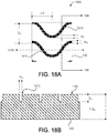
- FIGS. 18A and 18B illustrate a first tread pattern 1800 for the outsole 100 that includes grooves 1810 having a sinusoidal path along the ground contact surface 110 and equally spaced parallel to each other in a common direction.
- Each groove 1810 may have an amplitude A of about 5 mm, a frequency ⁇ of about 6.3 mm, a width W O of about 0.4 mm, and/or a depth D O of about 1.2 mm.
- the groove 1810 can have a wavelength ⁇ of about 6.3 mm.
- Each groove 1810 can be formed or cut to have a shoulder 1813 that defines right angle or substantially a right angle (e.g., a non-radiused, non-chamfered corner or a minimally radiused corner for mold release).
- the right angle edge style shoulder 1812 provides a traction edge for slip resistance.
- a sharp corner edge provides relatively better traction over a rounded corner.
- An axis of propagation 1815 of each groove 1810 can be offset from the axis of propagation 1815 of an adjacent groove 1810 by an offset distance O O of about 3.15 mm.
- the outsole 100 may have a thickness T of about 4 mm.
- the first tread pattern 1800 may have an edge density (e.g., of shoulder edges 1812) of about 79.5 mm/cm 2 and a surface contact ratio of about 84 %.
- FIGS. 19A and 19B illustrate a second tread pattern 1900 for the outsole 100 that includes grooves 1910 having a sinusoidal path along the ground contact surface 110 and equally spaced parallel to each other in a common direction.
- Each groove 1910 may have an amplitude A of about 5.25 mm, a frequency ⁇ of about 6.3 mm, a width Wp of about 0.25 mm, and/or a depth D P of about 1.2 mm.
- the groove 1910 can have a wavelength ⁇ of about 6.3 mm.
- Each groove 1910 can be formed or cut to have a shoulder 1912 that defines right angle or substantially a right angle (e.g., a non-radiused, non-chamfered corner or a minimally radiused corner for mold release).
- An axis of propagation 1915 of each groove 1910 can be offset from the axis of propagation 1915 of an adjacent groove 1910 by an offset distance Op of about 3 mm.
- the outsole 100 may have a thickness T of about 4 mm.
- the second tread pattern 1900 may have an edge density (e.g., of shoulder edges 1912) of about 77 mm/cm 2 and a surface contact ratio of about 90.5 %.
- FIGS. 20A and 20B illustrate a third tread pattern 2000 for the outsole 100 that includes grooves 2010 having a sinusoidal path along the ground contact surface 110 and equally spaced parallel to each other in a common direction.
- Each groove 2010 may have an amplitude A of about 5 mm, a frequency ⁇ of about 6.3 mm, a width W Q of about 0.4 mm, and/or a depth D Q of about 1.2 mm.
- the groove 2010 can have a wavelength ⁇ of about 6.3 mm.
- Each groove 2010 can be formed or cut to have a shoulder 2012 that defines right angle or substantially a right angle (e.g., a non-radiused, non-chamfered corner or a minimally radiused corner for mold release).
- An axis of propagation 2015 of each groove 1910 can be offset from the axis of propagation 2015 of an adjacent groove 2010 by an offset distance O Q of about 3.15 mm.
- the outsole 100 may have a thickness T of about 4 mm.
- Cross-linking grooves 1014 connecting adjacent grooves 1812 may have a width W Q of about 0.4 mm, and a depth D Q of about 0.6 mm.
- the third tread pattern 2000 may have an edge density (e.g., of shoulder edges 2012) of about 106 mm/cm 2 and a surface contact ratio of about 91 %.
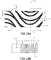
- FIGS. 21A and 21B illustrate a fourth tread pattern 2100 for the outsole 100 that includes grooves 2110 having a sinusoidal path along the ground contact surface 110 and equally spaced parallel to each other in a common direction.
- Each groove 2110 may have an amplitude A of about 17.6 mm, a frequency ⁇ of about 40 mm, a width W T of about 1 mm, and/or a depth D T of about 1.5 mm.
- the groove 2110 can have a wavelength ⁇ of about 20 mm.
- Each groove 2110 can be formed or cut to have a shoulder 2112 that defines right angle or substantially a right angle (e.g., a non-radiused, non-chamfered corner or a minimally radiused corner for mold release).
- An axis of propagation 2115 of each groove 2110 can be offset from the axis of propagation 2115 of an adjacent groove 2110 by an offset distance O T of between about 3 mm and about 3.75 mm.
- a first groove 2110 is offset from a second groove 2110 by an offset distance O T of about 3 mm
- the second groove 2110 is offset from a third groove 2110 by an offset distance O T of about 3.75 mm.
- the outsole 100 may have a thickness T of about 3.5 mm.
- the fourth tread pattern 2100 may have an edge density (e.g., of shoulder edges 2112) of about 59 mm/cm 2 and a surface contact ratio of about 67 %.
- FIGS. 22A and 22B illustrate a fifth tread pattern 2200 for the outsole 100 that includes razor siping or grooves 2210 having a sinusoidal or zig-zag path along the ground contact surface 110 and equally spaced parallel to each other in a common direction.
- Each groove 2210 may have an amplitude A of about 5.12 mm, a frequency ⁇ of about 6.5 mm, a width W W of about between 0 mm and about 0.25 mm, and/or a depth D W of about 1.2 mm.
- each groove 2210 can be cut to have a shoulder 2212 that defines right angle or substantially a right angle (e.g., a non-radiused, non-chamfered corner).
- An axis of propagation 2215 of each groove 2210 can be offset from the axis of propagation 2215 of an adjacent groove 2210 by an offset distance Op of about 5.12 mm.
- the outsole 100 may have a thickness T of about 5 mm.
- the fifth tread pattern 2200 may have an edge density (e.g., of shoulder edges 2212) of about 98 mm/cm 2 and a surface contact ratio of about 98 %.
- Anti-slip characteristics of the outsole 100 may depend on the ground contact surface configuration (e.g., tread pattern, edge density, and/or surface contact ratio) as well as the material of the outsole 100.
- the outsole 100 may be comprised of one or more materials.
- the outsole comprises at least one of natural rubber, rubber, 0.9 anti-slip rubber (rubber having a minimum coefficient of friction of 0.9 for a durometer of 50-55 Shore A), and 1.1 anti-slip rubber (rubber having a minimum coefficient of friction of 1.1 for a durometer of 50-55 Shore A), and latex, each having a durometer of between about 50 Shore A and about 65 Shore A.
- a slip resistance test can be performed to determine a slip index or slip angle for different combinations of tread configurations and outsole materials to select a tread configuration and outsole material appropriate for a particular application, such as boating, fishing, or activities on wet surfaces.
- the slip resistance test can be performed using a tribometer (also known as a slipmeter), which is an instrument that measures a degree of friction between two rubbing surfaces.
- the English XL Variable Incidence Tribometer (VIT) (available from Excel Tribometers, LLC, 160 Tymberbrook Drive, Lyman, SC 29365) is an exemplary Tribometer for determining slip resistance for various outsole configurations.
- the VIT instrument mimics biomechanical parameters of the human walking gait and replicates a heel strike of a human walking (e.g., using a leg and ankle device).
- a leg of the VIT instrument is free to accelerate once a slip occurs, as with a real-world human slip event.
- some testing instruments that drag across the floor at a constant rate do not account for what happens when humans slip and fall.
- the phenomenon of "sticktion” may produce misleading results when a walking surface is wet and the testing instrument has residence time before slip dynamics are applied. Testing instruments that drag across a wet test surface generally experience a micro-time jumping motion that is a series of "sticktion-release-sticktion-release" cycles.
- VIT Variable Incidence Tribometer
- Table 2 provides results of slip resistance tests conducted on a number of materials having the same surface configuration in wet and dry conditions in accordance with ASTM D1894 measuring a coefficient of friction between a smooth sample material (i.e., flat without treads) and a metal surface.
- Table 2 Material Durometer (Shore A) Slip Index Dry Slip Index Wet First Rubber 50-55 1.06 1.08 Second Rubber 60-65 0.96 0.85 0.9 Anti-Slip Rubber 50-55 1.16 1.03 0.9 Anti-Slip Rubber 60-65 0.74 0.70 1.1 Anti-Slip Rubber 50-55 1.57 1.52 Third Rubber 60-65 0.93 0.68 Latex 60-65 1.37 1.27
- Table 3 provides results of slip resistance tests conducted on a number of materials having the same surface configuration in wet and dry conditions in accordance with ASTM F1679-04 using a Variable Incidence Tribometer (VIT).
- a slip angle is the determined between a sample material and a test surface (e.g., a textured surface, Teak wood, Polyester-fiberglass, or metal).
- the sample material defined grooves having the third tread pattern (Q) 2000 described herein with reference to FIGS. 20A and 20B . Textured polyester fiberglass was used as the test surface for the results shown in Table 3.
- Table 4 provides results of slip resistance tests conducted on a number of materials having the same surface configuration in wet and dry conditions in accordance with ASTM F1679-04 using a Variable Incidence Tribometer (VIT).
- VIT Variable Incidence Tribometer
- the sample material defined grooves having the fourth tread pattern (T) 2100 described herein with reference to FIGS. 21A and 21B .
- Textured polyester fiberglass was used as the test surface for the results shown in Table 4.
- the slip resistance test results shown in Tables 2-4 reveal that the 1.1 Anti-Slip Rubber having a durometer of 50-55 Shore A out-performed the other samples, while latex having a durometer of 60-65 Shore A and the 0.9 Anti-Slip Rubber having a durometer of 50-55 Shore A performed relatively well in comparison to the remaining samples as well.
- the selection of an outsole material for an outsole 100 may depend on the combined performance of the material type and a tread configuration of the outsole 100.
- Table 5 provides results of slip resistance tests for different combinations of tread designs and outsole materials on Teak wood under 20 psi of pressure.
- a sixth sample is smooth with no treads as a control sample.
- Table 5 Tread Pattern Material Durometer (Shore A) VIT Slip Test Angle (°) Dry Wet First tread pattern 1800 (O) 0.9 Anti-Slip Rubber 50-55 44 42 Latex 50-55 40 39 Latex 60-65 40 40 Second tread pattern 1900 (P) 0.9 Anti-Slip Rubber 50-55 45 68 Latex 50-55 37 33 Latex 60-65 - - Third tread pattern 2000 (Q) 0.9 Anti-Slip Rubber 50-55 41 43 Latex 50-55 42 41 Latex 60-65 - - Fourth tread pattern 2100 (T) 0.9 Anti-Slip Rubber 50-55 43 42 Latex 50-55 40 40 Latex 60-65 43 41 Fifth tread pattern 2200 (W) 0.9 Anti-Slip Rubber 50-55 44 14 Latex 50-55 40 37 Latex 60-65 - - Smooth (no tread
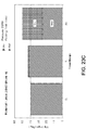
- FIGS. 23A-23C provide three graphs of the results shown in Table 5 separated by material type.
- the third and fourth tread patterns (Q, T) 2000, 2100 each perform substantially equally between wet and dry conditions, in addition to providing relatively high slip resistance.
- Table 6 provides results of slip resistance tests for different combinations of tread designs and outsole materials on Teak wood under 25 psi of pressure.
- a sixth sample is smooth with no treads as a control sample.
- Table 6 Tread Pattern Material Durometer (Shore A) VIT Slip Test Angle (°) Dry Wet First tread pattern 1800 (O) 0.9 Anti-Slip Rubber 50-55 47 43 Latex 50-55 40 39 Latex 60-65 40 40 Second tread pattern 1900 (P) 0.9 Anti-Slip Rubber 50-55 45 36 Latex 50-55 37 33 Latex 60-65 - - Third tread pattern 2000 (Q) 0.9 Anti-Slip Rubber 50-55 47 45 Latex 50-55 42 41 Latex 60-65 - - Fourth tread pattern 2100 (T) 0.9 Anti-Slip Rubber 50-55 44 43 Latex 50-55 40 40 Latex 60-65 43 41 Fifth tread pattern 2200 (W) 0.9 Anti-Slip Rubber 50-55 48 29 Latex 50-55 40 37 Latex 60-65 - - Smooth (no treads
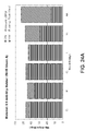
- FIGS. 24A-24C provide three graphs of the results shown in Table 6 separated by material type.
- the third and fourth tread patterns (Q, T) 2000, 2100 each perform substantially equally between wet and dry conditions, in addition to providing relatively high slip resistance.
- Table 7 provides results of slip resistance tests for different tread designs made of the 0.9 anti-slip rubber having durometer of 50-55 Shore A on Teak wood under 25 psi of pressure with a VIT instrument angle of 15°. A sixth sample is smooth with no treads as a control sample.
- Table 7 Tread Pattern VIT Slip Test Angle (°) Dry Wet First tread pattern 1800 (O) 47 43 Second tread pattern 1900 (P) 45 36 Third tread pattern 2000 (Q) 47 45 Fourth tread pattern 2100 (T) 44 43 Fifth tread pattern 2200 (W) 48 29 Smooth (no treads) (AA) 53 15
Landscapes
- Health & Medical Sciences (AREA)
- General Health & Medical Sciences (AREA)
- Physical Education & Sports Medicine (AREA)
- Footwear And Its Accessory, Manufacturing Method And Apparatuses (AREA)
Description
- This disclosure relates to outsoles for articles of footwear.
- Articles of footwear, such as shoes, are generally worn while exercising to protect and provide stability of a user's feet. In general, shoes include an upper portion and a sole. When the upper portion is secured to the sole, the upper portion and the sole together define a void that is configured to securely and comfortably hold a human foot. Often, the upper portion and/or sole are/is formed from multiple layers that can be stitched or adhesively bonded together. For example, the upper portion can be made of a combination of leather and fabric, or foam and fabric, and the sole can be formed from at least one layer of natural rubber. Often materials are chosen for functional reasons, e.g., water-resistance, durability, abrasion-resistance, and breathability, while shape, texture, and color are used to promote the aesthetic qualities of the shoe. The sole generally provides support for a user's foot and acts as an interface between the user's foot and the ground.
-
US 2010/0281714 A1 discloses a sole structure for an article of footwear, wherein the sole structure includes an outsole and a midsole. The outsole includes a tread pattern with a nonlinear configuration. A plurality of sipes are provided on the outsole and the midsole. The plurality of sipes have a nonlinear configuration that is substantially similar to the nonlinear configuration of the tread pattern. - Aspects of embodiments provide an outsole for an article of footwear, as defined in the claims. The claims define the scope of the invention.
- The details of one or more implementations of the disclosure are set forth in the accompanying drawings and the description below. Other aspects, features, and advantages will be apparent from the description and drawings, and from the claims.
-
-
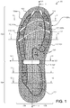
FIG. 1 is a bottom view of an exemplary sole assembly. -
FIG. 2 is a top view of the sole assembly shown inFIG. 1 . -
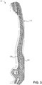
FIG. 3 is a lateral side view of the sole assembly shown inFIG. 1 . -
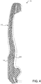
FIG. 4 is a medial side view of the sole assembly shown inFIG. 1 . -
FIG. 5 is a front view of the sole assembly shown inFIG. 1 . -
FIG. 6 is a rear view of the sole assembly shown inFIG. 1 . -
FIG. 7 is a section view of the sole assembly shown inFIG. 1 along line 7-7. -
FIG. 8 is a section view of the sole assembly shown inFIG. 1 along line 8-8. -
FIG. 9 is a section view of the sole assembly shown inFIG. 1 along line 9-9. -
FIG. 10 is a section view of the sole assembly shown inFIG. 1 along line 10-10. -
FIG. 11 is a section view of the sole assembly shown inFIG. 1 along line 11-11. -
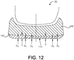
FIG. 12 is a section view of the sole assembly shown inFIG. 1 along line 12-12. -
FIG. 13 is a bottom view of a portion of an exemplary outsole having sinusoidal grooves. -
FIG. 14 is a section view of the outsole shown inFIG. 13 along line 14-14. -
FIG. 15 is a bottom view of a portion of an exemplary outsole having sinusoidal grooves. -
FIG. 16 is a section view of the outsole shown inFIG. 15 along line 16-16. -
FIG. 17 is a section view of the outsole shown inFIG. 15 along line 17-17. -
FIG. 18A is a bottom view of a portion of an exemplary outsole having sinusoidal grooves. -
FIG. 18B is a section view of the outsole shown inFIG. 18A alongline 18B-18B. -
FIG. 19A is a bottom view of a portion of an exemplary outsole having sinusoidal grooves. -
FIG. 19B is a section view of the outsole shown inFIG. 19A alongline 19B-19B. -
FIG. 20A is a bottom view of a portion of an exemplary outsole having sinusoidal grooves. -
FIG. 20B is a section view of the outsole shown inFIG. 20A alongline 20B-20B. -
FIG. 21A is a bottom view of a portion of an exemplary outsole having sinusoidal grooves. -
FIG. 21B is a section view of the outsole shown inFIG. 21A alongline 21B-21B. -
FIG. 22A is a bottom view of a portion of an exemplary outsole having sinusoidal or zig-zag style grooves. -
FIG. 22B is a section view of the outsole shown inFIG. 22A alongline 22B-22B. -
FIG. 23A is a chart of slip test resistance results under wet and dry conditions for various tread configurations of an outsole comprising a rubber having a coefficient of friction of 0.9 and a durometer of 50-55 Shore A. -
FIG. 23B is a chart of slip test resistance results under wet and dry conditions for various tread configurations of an outsole comprising latex having a durometer of 50-55 Shore A. -
FIG. 23C is a chart of slip test resistance results under wet and dry conditions for various tread configurations of an outsole comprising latex having a durometer of 60-65 Shore A. -
FIG. 24A is a chart of slip test resistance results under wet and dry conditions for various tread configurations of an outsole comprising a rubber having a coefficient of friction of 0.9 and a durometer of 50-55 Shore A. -
FIG. 24B is a chart of slip test resistance results under wet and dry conditions for various tread configurations of an outsole comprising latex having a durometer of 50-55 Shore A. -
FIG. 24C is a chart of slip test resistance results under wet and dry conditions for various tread configurations of an outsole comprising latex having a durometer of 60-65 Shore A. - Like reference symbols in the various drawings indicate like elements. By way of example only, all of the drawings are directed to an outsole for an article of footwear (e.g., a shoe) suitable to be worn on a user's right foot. The invention includes also the mirror images of the drawings, i.e. an outsole for an article of footwear suitable to be worn on the user's left foot.
- Referring to
FIGS. 1-7 , in some implementations, asole assembly 50 includes anoutsole 100 supporting amidsole 200. Theoutsole 100 has aforefoot portion 102, aheel portion 104 as well as alateral portion 106 and amedial portion 108. Theoutsole 100 also defines aground contact surface 110 for contacting the ground. Themidsole 200 can be made of ethylene vinyl acetate (EVA), foam, or any suitable material for providing cushioning in an article of footwear. - The
outsole 100 may have a tread configuration designed for slip resistance. For example, theground contact surface 110 of theoutsole 100 may define a plurality of grooves orchannels 112, such as siped grooves or slits, that receive water escaping from between theground contact surface 110 and the ground as theoutsole 100 is pressed against the ground (e.g., when thesole assembly 50 bears the weight of a user). Liquid can flow in the grooves orchannels 112 toward a perimeter of the outsole 100 (i.e., away from weight-bearing and contact surfaces). The grooves orchannels 112 may also be configured to provide flex regions of theoutsole 100, such as in theforefoot portion 102 to accommodate toe lifting of a user or flexing during walking or running. The grooves orchannels 112 may be adequately sized for liquid movement there-through, while deterring the accumulation of small objects therein. Moreover, the grooves orchannels 112 may flex open (e.g., during walking or running), providing traction and water escapement from theground contact surface 110. In some implementations, the grooves orchannels 112 are cut into theoutsole 100, while in other implementations, the grooves orchannels 112 are molded with theoutsole 100. The grooves orchannels 112 can have a width WG of between about 0.1 mm to about 5 mm (e.g., 1.2 mm) and/or a depth DG of between about 25% to about 75% of a thickness T of theoutsole 100. For example, for anoutsole 100 having a thickness of 3.5 mm, thegrooves 112 can have a depth D of between about 0.8 mm and about 2.6 mm (e.g., a depth D of 1 mm, 2 mm, or 2.5 mm).Siped grooves 112 may have a relatively thin width WG as compared to other types ofgrooves 112.Siped grooves 112 may be formed by razor cutting thegroove 112 into theoutsole 100 or molding thegroove 112 with a relatively narrow width WG. - In the examples shown, the
outsole 100 defines first andsecond tread regions 120, 130; however, theoutsole 100 may define one contiguous tread region or many tread regions arranged randomly or in specific locations on theground contact surface 110. Eachtread region 120, 130 includes a corresponding configuration grooves orchannels ground contact surface 110 from the grooves orchannels 122, 132) within a square centimeter. In general, the greater the edge density, the greater the traction; however, manufacturability, aesthetics, resistance to wear and other factors may limit the edge density. The surface contact ratio is defined as an overall area of theground contact surface 110 minus a groove area of the ground contact surface 110 (i.e. an area of the ground contact surface removed for the grooves orchannels 122, 132) divided by the overall area of theground contact surface 110. In dry conditions, a surface contact ratio of 100% can provide the best traction; however, aground contact surface 110 with no grooves orchannels ground contact surface 110 can provide certain traction and performance characteristics of theoutsole 100 in various environmental conditions. - The grooves or
channels outsole 100 can be arranged to provide an edge density of between about 40 mm/cm2 and about 200 mm/cm2 and/or a surface contact ratio of between about 40% and about 95%. In some implementations, the grooves orchannels outsole 100 are arranged to provide an edge density of between about 100 mm/cm2 and about 110 mm/cm2 and/or a surface contact ratio of between about 50% and about 95%. Moreover, the grooves orchannels ground contact surface 110. For example, the sinusoidal path of the grooves orchannels 
- where t is time, A is amplitude, ω is angular frequency and φ is phase at a time of t = 0. Referring to
FIG. 1-7 and15-17 , a tread pattern for theoutsole 100 may includegrooves Table 1 Parameter Value Edge Density 40-200 mm/cm2 Surface Contact Ratio 40% - 90% Amplitude (A) of Sinusoidal Path 3 mm - 25 mm Frequency (ω) of Sinusoidal Path 4 mm - 50 mm Groove Offset (OG) 2 mm - 5 mm Groove Width (WG) 0.1 mm - 5 mm Groove Depth (DG) 25-75% of outsole thickness Groove Edge Angle (α) 75° - 150° Outsole Compound Durometer 45-65 Shore A - Referring to
FIGS. 13-17 , in some examples, the sinusoidal path of agroove channels channels ground contact surface 110. The grooves orchannels 122 each have a width WT, WQ of between about 0.1 mm and about 1 mm (e.g., 0.5 mm) and a depth DT, DQ of between about 25% and about 75% of a thickness T of theoutsole 100. For example, for anoutsole 100 having a thickness of 3.5 mm, the grooves orchannels - Referring to
FIGS. 1-17 , in some implementations, the first andsecond tread regions 120, 132 define grooves orchannels FIGS. 8-12 , the grooves orchannels FIGS. 13-17 ) that defines a right angle or substantially at right angle (e.g., a non-radiused, non-chamfered corner or a minimally radiused corner for mold release). Other shoulder configurations are possible as well. The right angleedge style shoulder 123, 133 provides a traction edge for slip resistance. A sharp corner edge provides relatively better traction over a rounded corner, since the sharp edge can catch on surface features of the ground. As theoutsole 100 flexes, each shoulder oredge 123, 133 can grab the ground for traction. Each shoulder oredge 123, 133 within a square centimeter can be counted for determining the edge density of that corresponding region of theoutsole 100. - Referring to
FIGS. 1 ,13 and 14 , in some implementations, the first tread region 120 defines grooves orchannels 122 propagating in a wave pattern with an axis of propagation 125 (FIG. 13 ) substantially parallel to alongitudinal axis 101 of theoutsole 100. The first tread region 120 provides traction for lateral movements of theoutsole 100 against the ground, such as side-to-side movements by a user. The groove or channel arrangement places a relatively longer leading edge 123 of each groove orchannel 122 perpendicular to a direction of slip, thus providing slip resistance against forces substantially parallel to atransverse axis 103 of theoutsole 100. In the example shown, theoutsole 100 includes a lateral first tread region 120a and a medial first tread region 120b disposed on corresponding lateral andmedial portions outsole 100. The lateral first tread region 120a can be arranged near alateral perimeter 106a of theoutsole 100 and the medial first tread region 120b can be arranged near amedial perimeter 108a of theoutsole 100. Thesecond tread region 130 can be arranged between the lateral first tread region 120a and the medial first tread region 120b in at least aground striking portion 107 of the outsole 100 (e.g., substantially under the heel and metatarsal of a user's foot). As a user moves side-to-side, weight can be placed on the respective lateral andmedial potions outsole 100. The respective lateral and medial first tread regions 120a, 120b can provide traction or slip resistance against forces incurred by theground contact surface 110 along thetransverse axis 103 of theoutsole 100. - In some examples, each grooves or
channels 122 follows a sinusoidal path with an amplitude of about 8.8 mm (or 8.8 mm +/- 1 or 2 mm) and an angular frequency of about 20 mm (or 20 mm +/- 3 mm). Each grove orchannel 122 can have a width WT of about 0.5 mm and/or a depth DT of about 1.5 mm. Theoutsole 100 can have thickness T of about 3.5 mm in the first tread region 120. In some implementations, the axis ofpropagation 125 of each grove orchannel 122 is offset from the axis ofpropagation 125 of an adjacent grove orchannel 122 by an offset distance OT of between about 1 mm and about 2 mm. Adjacent grooves orchannels 122 can be arranged such that their corresponding groove paths merge at various orperiodic groove intersections 127. The first tread region 120 may have an edge density of groove edges 123 of about 124 mm/cm2 and a surface contact ratio of about 65 %. - Referring to
FIGS. 1 and15-17 , in some implementations, thesecond tread region 130 definesgrooves 132 propagating in a wave pattern with an axis of propagation 135 (FIG. 15 ) substantially parallel to thetransverse axis 103 of theoutsole 100. Thesecond tread region 130 provides traction for forward and rearward movements of theoutsole 100 against the ground along a walking direction of the user. The groove arrangement places a relatively longer leading edge 123 of eachgroove 122 perpendicular to a direction of slip, thus providing slip resistance against forces on theground contact surface 110 substantially parallel to thelongitudinal axis 101 of the outsole 100 (as during walking or running along a normal walking direction (forward or reverse)). - In some examples, each
grooves 132 follows a sinusoidal path with an amplitude A of 5 mm (or 5 mm +/- 1 or 2 mm) and an angular frequency ω of 6.3 mm (or 6.3 mm +/- 1 or 2 mm). Eachgrove 132 can have a width WQ of about 0.4 mm, a depth DQ of about 1.2 mm. Theoutsole 100 can have thickness T of about 4 mm in thesecond tread region 130. In some implementations, the axis ofpropagation 135 of eachgrove 132 is offset from the axis ofpropagation 135 of anadjacent grove 132 by an offset distance OQ of between about 1.5 mm and about 3.5 mm (e.g., about 2.75 mm). Moreover, branch orcross-linking grooves 134 interconnect adjacent grooves 132 (e.g., every quarter or half a wavelength of the sinusoidal grooves 132). Thebranch grooves 134 extend in a direction substantially parallel to or at a relatively small angle (e.g., between about 1° and about 45°) with respect to thelongitudinal axis 101. Thebranch grooves 134 may have a width WQ of about 0.4 mm, a depth DQ of about 0.6 mm (or about half the depth DQ of the other grooves and siping 132). Thesecond tread region 130 may have an edge density of siping edges 133 of about 106 mm/cm2 and a surface contact ratio of about 91 %. -
FIGS. 18A-22B depict a number of outsole tread patterns.FIGS. 18A and 18B illustrate afirst tread pattern 1800 for theoutsole 100 that includesgrooves 1810 having a sinusoidal path along theground contact surface 110 and equally spaced parallel to each other in a common direction. Eachgroove 1810 may have an amplitude A of about 5 mm, a frequency ω of about 6.3 mm, a width WO of about 0.4 mm, and/or a depth DO of about 1.2 mm. Moreover, thegroove 1810 can have a wavelength λ of about 6.3 mm. Eachgroove 1810 can be formed or cut to have a shoulder 1813 that defines right angle or substantially a right angle (e.g., a non-radiused, non-chamfered corner or a minimally radiused corner for mold release). The right angleedge style shoulder 1812 provides a traction edge for slip resistance. A sharp corner edge provides relatively better traction over a rounded corner. An axis ofpropagation 1815 of eachgroove 1810 can be offset from the axis ofpropagation 1815 of anadjacent groove 1810 by an offset distance OO of about 3.15 mm. Theoutsole 100 may have a thickness T of about 4 mm. Thefirst tread pattern 1800 may have an edge density (e.g., of shoulder edges 1812) of about 79.5 mm/cm2 and a surface contact ratio of about 84 %. -
FIGS. 19A and 19B illustrate asecond tread pattern 1900 for theoutsole 100 that includesgrooves 1910 having a sinusoidal path along theground contact surface 110 and equally spaced parallel to each other in a common direction. Eachgroove 1910 may have an amplitude A of about 5.25 mm, a frequency ω of about 6.3 mm, a width Wp of about 0.25 mm, and/or a depth DP of about 1.2 mm. Moreover, thegroove 1910 can have a wavelength λ of about 6.3 mm. Eachgroove 1910 can be formed or cut to have ashoulder 1912 that defines right angle or substantially a right angle (e.g., a non-radiused, non-chamfered corner or a minimally radiused corner for mold release). An axis ofpropagation 1915 of eachgroove 1910 can be offset from the axis ofpropagation 1915 of anadjacent groove 1910 by an offset distance Op of about 3 mm. Theoutsole 100 may have a thickness T of about 4 mm. Thesecond tread pattern 1900 may have an edge density (e.g., of shoulder edges 1912) of about 77 mm/cm2 and a surface contact ratio of about 90.5 %. -
FIGS. 20A and 20B illustrate a third tread pattern 2000 for theoutsole 100 that includesgrooves 2010 having a sinusoidal path along theground contact surface 110 and equally spaced parallel to each other in a common direction. Eachgroove 2010 may have an amplitude A of about 5 mm, a frequency ω of about 6.3 mm, a width WQ of about 0.4 mm, and/or a depth DQ of about 1.2 mm. Moreover, thegroove 2010 can have a wavelength λ of about 6.3 mm. Eachgroove 2010 can be formed or cut to have ashoulder 2012 that defines right angle or substantially a right angle (e.g., a non-radiused, non-chamfered corner or a minimally radiused corner for mold release). An axis ofpropagation 2015 of eachgroove 1910 can be offset from the axis ofpropagation 2015 of anadjacent groove 2010 by an offset distance OQ of about 3.15 mm. Theoutsole 100 may have a thickness T of about 4 mm. Cross-linking grooves 1014 connectingadjacent grooves 1812 may have a width WQ of about 0.4 mm, and a depth DQ of about 0.6 mm. The third tread pattern 2000 may have an edge density (e.g., of shoulder edges 2012) of about 106 mm/cm2 and a surface contact ratio of about 91 %. -
FIGS. 21A and 21B illustrate afourth tread pattern 2100 for theoutsole 100 that includesgrooves 2110 having a sinusoidal path along theground contact surface 110 and equally spaced parallel to each other in a common direction. Eachgroove 2110 may have an amplitude A of about 17.6 mm, a frequency ω of about 40 mm, a width WT of about 1 mm, and/or a depth DT of about 1.5 mm. Moreover, thegroove 2110 can have a wavelength λ of about 20 mm. Eachgroove 2110 can be formed or cut to have ashoulder 2112 that defines right angle or substantially a right angle (e.g., a non-radiused, non-chamfered corner or a minimally radiused corner for mold release). An axis of propagation 2115 of eachgroove 2110 can be offset from the axis of propagation 2115 of anadjacent groove 2110 by an offset distance OT of between about 3 mm and about 3.75 mm. In the example, for threeconsecutive grooves 2110, afirst groove 2110 is offset from asecond groove 2110 by an offset distance OT of about 3 mm, and thesecond groove 2110 is offset from athird groove 2110 by an offset distance OT of about 3.75 mm. Theoutsole 100 may have a thickness T of about 3.5 mm. Thefourth tread pattern 2100 may have an edge density (e.g., of shoulder edges 2112) of about 59 mm/cm2 and a surface contact ratio of about 67 %. -
FIGS. 22A and 22B illustrate afifth tread pattern 2200 for theoutsole 100 that includes razor siping orgrooves 2210 having a sinusoidal or zig-zag path along theground contact surface 110 and equally spaced parallel to each other in a common direction. Eachgroove 2210 may have an amplitude A of about 5.12 mm, a frequency ω of about 6.5 mm, a width WW of about between 0 mm and about 0.25 mm, and/or a depth DW of about 1.2 mm. Moreover, eachgroove 2210 can be cut to have ashoulder 2212 that defines right angle or substantially a right angle (e.g., a non-radiused, non-chamfered corner). An axis ofpropagation 2215 of eachgroove 2210 can be offset from the axis ofpropagation 2215 of anadjacent groove 2210 by an offset distance Op of about 5.12 mm. Theoutsole 100 may have a thickness T of about 5 mm. Thefifth tread pattern 2200 may have an edge density (e.g., of shoulder edges 2212) of about 98 mm/cm2 and a surface contact ratio of about 98 %. - Anti-slip characteristics of the
outsole 100 may depend on the ground contact surface configuration (e.g., tread pattern, edge density, and/or surface contact ratio) as well as the material of theoutsole 100. Theoutsole 100 may be comprised of one or more materials. The outsole comprises at least one of natural rubber, rubber, 0.9 anti-slip rubber (rubber having a minimum coefficient of friction of 0.9 for a durometer of 50-55 Shore A), and 1.1 anti-slip rubber (rubber having a minimum coefficient of friction of 1.1 for a durometer of 50-55 Shore A), and latex, each having a durometer of between about 50 Shore A and about 65 Shore A. - A slip resistance test can be performed to determine a slip index or slip angle for different combinations of tread configurations and outsole materials to select a tread configuration and outsole material appropriate for a particular application, such as boating, fishing, or activities on wet surfaces. The slip resistance test can be performed using a tribometer (also known as a slipmeter), which is an instrument that measures a degree of friction between two rubbing surfaces. The English XL Variable Incidence Tribometer (VIT) (available from Excel Tribometers, LLC, 160 Tymberbrook Drive, Lyman, SC 29365) is an exemplary Tribometer for determining slip resistance for various outsole configurations. The VIT instrument mimics biomechanical parameters of the human walking gait and replicates a heel strike of a human walking (e.g., using a leg and ankle device). A leg of the VIT instrument is free to accelerate once a slip occurs, as with a real-world human slip event. For example, some testing instruments that drag across the floor at a constant rate do not account for what happens when humans slip and fall. Moreover, the phenomenon of "sticktion" may produce misleading results when a walking surface is wet and the testing instrument has residence time before slip dynamics are applied. Testing instruments that drag across a wet test surface generally experience a micro-time jumping motion that is a series of "sticktion-release-sticktion-release" cycles. The dynamics of the VIT instrument permits measurement of slip resistance in wet conditions because there is no residence time. ASTM F1679-04 provides a test method for using a Variable Incidence Tribometer (VIT). ANSI A1264.2 provides a provision of slip resistance in the workplace.
- Table 2 provides results of slip resistance tests conducted on a number of materials having the same surface configuration in wet and dry conditions in accordance with ASTM D1894 measuring a coefficient of friction between a smooth sample material (i.e., flat without treads) and a metal surface.
Table 2 Material Durometer (Shore A) Slip Index Dry Slip Index Wet First Rubber 50-55 1.06 1.08 Second Rubber 60-65 0.96 0.85 0.9 Anti-Slip Rubber 50-55 1.16 1.03 0.9 Anti-Slip Rubber 60-65 0.74 0.70 1.1 Anti-Slip Rubber 50-55 1.57 1.52 Third Rubber 60-65 0.93 0.68 Latex 60-65 1.37 1.27 - Table 3 provides results of slip resistance tests conducted on a number of materials having the same surface configuration in wet and dry conditions in accordance with ASTM F1679-04 using a Variable Incidence Tribometer (VIT). A slip angle is the determined between a sample material and a test surface (e.g., a textured surface, Teak wood, Polyester-fiberglass, or metal). The sample material defined grooves having the third tread pattern (Q) 2000 described herein with reference to
FIGS. 20A and 20B . Textured polyester fiberglass was used as the test surface for the results shown in Table 3.Table 3 Material Durometer (Shore A) Dry Slip Angle (Deg.) Wet Slip Angle (Deg.) First Rubber 50-55 46 46 Second Rubber 60-65 39 - 0.9 Anti-Slip Rubber 50-55 54 53 0.9 Anti-Slip Rubber 60-65 43 42 1.1 Anti-Slip Rubber 50-55 56 57 1.1 Anti-Slip Rubber 60-65 46 47 Third Rubber 60-65 45 42 Latex 50-55 47 47 Latex 60-65 55 38 - Table 4 provides results of slip resistance tests conducted on a number of materials having the same surface configuration in wet and dry conditions in accordance with ASTM F1679-04 using a Variable Incidence Tribometer (VIT). The sample material defined grooves having the fourth tread pattern (T) 2100 described herein with reference to
FIGS. 21A and 21B . Textured polyester fiberglass was used as the test surface for the results shown in Table 4.Table 4 Material Durometer (Shore A) Dry Slip Angle (Deg.) Wet Slip Angle (Deg.) First Rubber 50-55 47 42 Second Rubber 60-65 37 - 0.9 Anti-Slip Rubber 50-55 54 52 0.9 Anti-Slip Rubber 60-65 48 46 1.1 Anti-Slip Rubber 50-55 55 56 1.1 Anti-Slip Rubber 60-65 46 48 Third Rubber 60-65 38 35 Latex 50-55 45 46 Latex 60-65 58 40 - The slip resistance test results shown in Tables 2-4 reveal that the 1.1 Anti-Slip Rubber having a durometer of 50-55 Shore A out-performed the other samples, while latex having a durometer of 60-65 Shore A and the 0.9 Anti-Slip Rubber having a durometer of 50-55 Shore A performed relatively well in comparison to the remaining samples as well. The selection of an outsole material for an
outsole 100 may depend on the combined performance of the material type and a tread configuration of theoutsole 100. - Table 5 provides results of slip resistance tests for different combinations of tread designs and outsole materials on Teak wood under 20 psi of pressure. A sixth sample is smooth with no treads as a control sample.
Table 5 Tread Pattern Material Durometer (Shore A) VIT Slip Test Angle (°) Dry Wet First tread pattern 1800 (O) 0.9 Anti-Slip Rubber 50-55 44 42 Latex 50-55 40 39 Latex 60-65 40 40 Second tread pattern 1900 (P) 0.9 Anti-Slip Rubber 50-55 45 68 Latex 50-55 37 33 Latex 60-65 - - Third tread pattern 2000 (Q) 0.9 Anti-Slip Rubber 50-55 41 43 Latex 50-55 42 41 Latex 60-65 - - Fourth tread pattern 2100 (T) 0.9 Anti-Slip Rubber 50-55 43 42 Latex 50-55 40 40 Latex 60-65 43 41 Fifth tread pattern 2200 (W) 0.9 Anti-Slip Rubber 50-55 44 14 Latex 50-55 40 37 Latex 60-65 - - Smooth (no treads) (AA) 0.9 Anti-Slip Rubber 50-55 47 43 Latex 50-55 43 7 Latex 60-65 50 25 -
FIGS. 23A-23C provide three graphs of the results shown in Table 5 separated by material type. The third and fourth tread patterns (Q, T) 2000, 2100 each perform substantially equally between wet and dry conditions, in addition to providing relatively high slip resistance. - Table 6 provides results of slip resistance tests for different combinations of tread designs and outsole materials on Teak wood under 25 psi of pressure. A sixth sample is smooth with no treads as a control sample.
Table 6 Tread Pattern Material Durometer (Shore A) VIT Slip Test Angle (°) Dry Wet First tread pattern 1800 (O) 0.9 Anti-Slip Rubber 50-55 47 43 Latex 50-55 40 39 Latex 60-65 40 40 Second tread pattern 1900 (P) 0.9 Anti-Slip Rubber 50-55 45 36 Latex 50-55 37 33 Latex 60-65 - - Third tread pattern 2000 (Q) 0.9 Anti-Slip Rubber 50-55 47 45 Latex 50-55 42 41 Latex 60-65 - - Fourth tread pattern 2100 (T) 0.9 Anti-Slip Rubber 50-55 44 43 Latex 50-55 40 40 Latex 60-65 43 41 Fifth tread pattern 2200 (W) 0.9 Anti-Slip Rubber 50-55 48 29 Latex 50-55 40 37 Latex 60-65 - - Smooth (no treads) (AA) 0.9 Anti-Slip Rubber 50-55 53 15 Latex 50-55 43 7 Latex 60-65 50 25 -
FIGS. 24A-24C provide three graphs of the results shown in Table 6 separated by material type. The third and fourth tread patterns (Q, T) 2000, 2100 each perform substantially equally between wet and dry conditions, in addition to providing relatively high slip resistance. - Table 7 provides results of slip resistance tests for different tread designs made of the 0.9 anti-slip rubber having durometer of 50-55 Shore A on Teak wood under 25 psi of pressure with a VIT instrument angle of 15°. A sixth sample is smooth with no treads as a control sample.
Table 7 Tread Pattern VIT Slip Test Angle (°) Dry Wet First tread pattern 1800 (O) 47 43 Second tread pattern 1900 (P) 45 36 Third tread pattern 2000 (Q) 47 45 Fourth tread pattern 2100 (T) 44 43 Fifth tread pattern 2200 (W) 48 29 Smooth (no treads) (AA) 53 15 - A number of implementations have been described. Nevertheless, it will be understood that various modifications may be made without departing from the scope of the following claims.
Claims (11)
- An outsole (100) for an article of footwear, the outsole (100) comprising:
an outsole body (100) having a ground contact surface (110, 310) and defining grooves (112, 122, 132, 1810, 2110) having a sinusoidal path along the ground contact surface (110, 310), wherein:each groove includes at least one shoulder edge with the ground contact surface, the shoulder edge defining a right angle with a non-radiused corner, each edge defining a length;the grooves (112, 122, 132, 1810, 2110) provide an edge density of between 40 mm/cm2 and 200 mm/cm2 and a surface contact ratio of between 40% and 95%;adjacent grooves (112, 122, 132, 1810, 2110) having a sinusoidal path are intersected by a plurality of branch grooves (134), wherein the plurality of branch grooves (134) are transverse to the adjacent grooves (112, 122, 132, 1810, 2110) having a sinusoidal path, and wherein the plurality of branch grooves (134) extend in a direction substantially parallel to, or at an angle between about 1° and about 45° with respect to, a longitudinal axis (101) of the outsole body (100);the surface contact ratio is an overall area of the ground contact surface (110, 310) minus an area of the ground contact surface (110, 310) occupied by the grooves (112, 122, 132, 1810, 2110), divided by the overall area of the ground contact surface (110, 310);the edge density is a cumulative length of the edges of the ground contact surface (110, 310) from the grooves within a square centimeter;the grooves (112, 122, 132, 1810 and 2110) have a width (WO, WT, WQ) of 0.1 mm to 1.0 mm; andthe outsole body (100) comprises at least one of a rubber having a durometer of between 45 Shore A and 65 Shore A, a rubber having a minimum coefficient of friction of 0.9 and a durometer of between 50 Shore A and 65 Shore A, and a rubber having a minimum coefficient of friction of 1.1 and a durometer of between 50 Shore A and 65 Shore A. - The outsole (100) of claim 1, wherein at least some of the sinusoidal grooves (112, 122, 132, 1810, 2110) are arranged parallel to each other to provide an edge density of 59 mm/cm2 and a surface contact ratio of 67%, or an edge density of 106 mm/cm2 and a surface contact ratio of 91%, or an edge density of 80 mm/cm2 and a surface contact ratio of 84%, or an edge density of 77 mm/cm2 and a surface contact ratio of 90%.
- The outsole (100) of claim 1, wherein the groove (112, 122, 132, 1810, 2110) of at least one sinusoidal groove path has a width (WO, WT, WQ) of 0.4 mm and/or a depth (DQ) of 1.2 mm.
- The outsole (100) of claim 1 or 2, wherein each groove (112, 122, 132, 1810, 2110) has a sinusoidal groove path along the ground contact surface (110) having an amplitude (A) of 5 mm and a frequency (ω) of 6.3 mm, adjacent grooves (112, 122, 132, 1810, 2110) being offset from each other along the ground contact surface (110) in a common direction by an offset distance (OQ, OO) of 3.15 mm.
- The outsole (100) of claim 4, wherein each of the plurality of branch grooves (134) has a depth (DQ) of half a depth (DQ) of the grooves (112, 122, 132, 1810, 2110) and/or a width (WQ) equal to a width (WQ) of the grooves (112, 122, 132, 1810, 2110).
- The outsole (100) of claim 1 or 2, wherein at least one sinusoidal groove path along the ground contact surface (110) has an amplitude (A) of 17.6 mm and a frequency (ω) of 40 mm, and preferably the corresponding groove (112, 122, 132, 1810, 2110) of the at least one sinusoidal groove path has a width (WT) of 1 mm and/or a depth (DT) of 1.5 mm.
- The outsole (100) of claim 6, wherein the adjacent grooves (112, 122, 132, 1810, 2110) are offset from each other along the ground contact surface (110) in a common direction by an offset distance (OT) of between 3 mm and 3.75 mm, and preferably, for first to third consecutive grooves (112, 122, 132, 1810, 2110) along the ground contact surface (110), the first groove (112, 122, 132, 1810, 2110) is offset from the second groove (112, 122, 132, 1810, 2110) by an offset distance (OT) of 3 mm and the second groove (112, 122, 132, 1810, 2110) is offset from the third groove (112, 122, 132, 1810, 2110) by an offset distance (OT) of 3.75 mm.
- The outsole (100) of claim 1 or 2, wherein adjacent grooves (112, 122, 132, 1810, 2110) are offset from each other along the ground contact surface (110) in a common direction by an offset distance (OQ), preferably of 3.15 mm.
- The outsole (100) of claim 8, wherein each of the plurality of branch grooves (134) has a depth (DQ) of half a depth (DQ) of the grooves (112, 122, 132, 1810, 2110) and/or a width (WQ) equal to a width (WQ) of the grooves (112, 122, 132, 1810, 2110).
- The outsole (100) of claim 8 or 9, wherein the grooves (112, 122, 132, 1810, 2110) are arranged parallel to each other to provide an edge density of 106 mm/cm2 and a surface contact ratio of 91%.
- The outsole (100) of claim 1, wherein:the outsole body (100) has a lateral portion (106) and a medial portion (108), the outsole (100) defining a longitudinal axis (101) along a walking direction and a perpendicular transverse axis (103);the ground contact surface (110) hasa first tread region (120a) disposed on the lateral outsole body portion (106) near a lateral periphery of the outsole (100),a second tread region (120b) disposed on the medial outsole body portion (108) near a medial periphery of the outsole (100), anda third tread region (130) disposed between the first and second tread regions (120a, 120b) in at least a ground striking portion of the outsole (100);the first and second tread regions (120a, 120b) define grooves (112, 122, 132, 1810, 2110) having a sinusoidal path along the ground contact surface (110) with an axis of propagation (125) parallel to the longitudinal axis (101) of the outsole (100), adjacent ones of those grooves (112, 122, 132, 1810, 2110) being offset from each other along the transverse axis (103) by a first offset distance (OT); andthe third tread region (130) defines grooves (112, 122, 132, 1810, 2110) having a sinusoidal path along the ground contact surface (110) with an axis of propagation (135) parallel to the transverse axis (103) of the outsole (100), adjacent ones of those grooves (112, 122, 132, 1810, 2110) being offset from each other along the longitudinal axis (101) by a second offset distance (OQ).
Applications Claiming Priority (2)
| Application Number | Priority Date | Filing Date | Title |
|---|---|---|---|
| US201161432317P | 2011-01-13 | 2011-01-13 | |
| PCT/US2011/048408 WO2012096690A2 (en) | 2011-01-13 | 2011-08-19 | Footwear outsole |
Publications (2)
| Publication Number | Publication Date |
|---|---|
| EP2663207A1 EP2663207A1 (en) | 2013-11-20 |
| EP2663207B1 true EP2663207B1 (en) | 2018-05-30 |
Family
ID=44515063
Family Applications (1)
| Application Number | Title | Priority Date | Filing Date |
|---|---|---|---|
| EP11749313.0A Active EP2663207B1 (en) | 2011-01-13 | 2011-08-19 | Footwear outsole |
Country Status (6)
| Country | Link |
|---|---|
| US (3) | US8726540B2 (en) |
| EP (1) | EP2663207B1 (en) |
| CN (1) | CN103476287B (en) |
| CA (2) | CA2743893C (en) |
| ES (1) | ES2685584T3 (en) |
| WO (3) | WO2012096690A2 (en) |
Families Citing this family (154)
| Publication number | Priority date | Publication date | Assignee | Title |
|---|---|---|---|---|
| US8789295B2 (en) | 2011-02-08 | 2014-07-29 | Wolverine World Wide, Inc. | Footwear and related method of manufacture |
| FR2975875B1 (en) * | 2011-06-06 | 2013-05-24 | Millet | LOWER SOLE OF CLIMBING SHOE |
| US9626461B2 (en) * | 2011-07-19 | 2017-04-18 | Sculpteo | Method for creating personalized functional objects, computer, computer readable medium and computer program related thereto |
| USD672949S1 (en) * | 2011-09-07 | 2012-12-25 | Vibram S.P.A. | Sole for footwear |
| US9038288B2 (en) * | 2011-09-26 | 2015-05-26 | Nike, Inc. | Athletic footwear with ball control portions |
| US8991075B2 (en) * | 2011-11-10 | 2015-03-31 | S9, Llc | Three toed footwear |
| US20130118036A1 (en) * | 2011-11-10 | 2013-05-16 | Deckers Outdoor Corporation | Footwear outsole inlcuding gripping tread |
| US9009989B2 (en) * | 2012-02-06 | 2015-04-21 | Keen, Inc. | Footwear with hydroplaning-resistant outsole and camouflaged toe cap |
| USD671305S1 (en) * | 2012-03-30 | 2012-11-27 | Strategic Partners, Inc. | Outsole |
| USD671306S1 (en) * | 2012-03-30 | 2012-11-27 | Strategic Partners, Inc. | Outsole |
| JP5221811B1 (en) * | 2012-11-29 | 2013-06-26 | 敦洋 石川 | Athletic footwear |
| USD734603S1 (en) * | 2013-01-23 | 2015-07-21 | Honeywell International, Inc. | Shoe outsole |
| USD727610S1 (en) * | 2013-01-23 | 2015-04-28 | Honeywell International Inc. | Shoe outsole |
| USD725358S1 (en) * | 2013-01-23 | 2015-03-31 | Honeywell International Inc. | Shoe outsole |
| USD733415S1 (en) * | 2013-02-13 | 2015-07-07 | J. Choo Limited | Sole for footwear |
| USD724831S1 (en) * | 2013-02-13 | 2015-03-24 | J. Choo Limited | Sole for footwear |
| USD732811S1 (en) * | 2013-02-13 | 2015-06-30 | J. Choo Limited | Sole for footwear |
| USD684347S1 (en) * | 2013-02-27 | 2013-06-18 | Nike, Inc. | Shoe outsole |
| US9320316B2 (en) | 2013-03-14 | 2016-04-26 | Under Armour, Inc. | 3D zonal compression shoe |
| US10499706B2 (en) | 2013-03-22 | 2019-12-10 | Reebok International Limited | Molded footwear upper and method of making same |
| USD719336S1 (en) * | 2013-07-26 | 2014-12-16 | Nike, Inc. | Sole for a cleated shoe |
| US10945488B2 (en) | 2013-08-09 | 2021-03-16 | Reebok International Limited | Article of footwear with extruded components |
| US10136684B2 (en) * | 2013-08-27 | 2018-11-27 | Solite Innovations LLC | Molded watersports and cold climate accessories |
| US9833039B2 (en) * | 2013-09-27 | 2017-12-05 | Nike, Inc. | Uppers and sole structures for articles of footwear |
| USD707935S1 (en) * | 2013-11-12 | 2014-07-01 | Nike, Inc. | Shoe outsole |
| USD708830S1 (en) * | 2013-11-12 | 2014-07-15 | Nike, Inc. | Shoe outsole |
| USD704424S1 (en) * | 2013-11-12 | 2014-05-13 | Nike, Inc. | Shoe outsole |
| USD709276S1 (en) * | 2013-11-30 | 2014-07-22 | Nike, Inc. | Shoe outsole |
| USD707934S1 (en) * | 2013-11-30 | 2014-07-01 | Nike, Inc. | Shoe outsole |
| USD753376S1 (en) | 2013-12-13 | 2016-04-12 | Reebok International Limited | Shoe |
| US9930929B2 (en) * | 2013-12-27 | 2018-04-03 | Nike, Inc. | Sole structure for an article of footwear with abrasion resistant outsole and method of manufacturing same |
| US9375051B2 (en) | 2014-01-22 | 2016-06-28 | Nike, Inc. | Article with coloring layer and control surface layer |
| USD743155S1 (en) * | 2014-01-31 | 2015-11-17 | Benjamin Ransom | Patterned shoe sole |
| USD744735S1 (en) * | 2014-02-07 | 2015-12-08 | New Balance Athletic Shoe, Inc. | Shoe sole |
| USD734602S1 (en) * | 2014-02-10 | 2015-07-21 | Genesco Licensed Brands | Footwear grip |
| EP3104733B1 (en) | 2014-02-12 | 2020-06-03 | New Balance Athletics, Inc. | Sole for footwear, and systems and methods for designing and manufacturing same |
| USD708831S1 (en) * | 2014-02-28 | 2014-07-15 | Nike, Inc. | Shoe outsole |
| USD713629S1 (en) * | 2014-02-28 | 2014-09-23 | Nike, Inc. | Shoe outsole |
| USD710582S1 (en) * | 2014-02-28 | 2014-08-12 | Nike, Inc. | Shoe outsole |
| US9526296B2 (en) | 2014-03-13 | 2016-12-27 | Nike, Inc. | Article of footwear for athletic and recreational activities |
| US9380834B2 (en) | 2014-04-22 | 2016-07-05 | Nike, Inc. | Article of footwear with dynamic support |
| EP3143892B1 (en) * | 2014-05-14 | 2018-09-19 | ASICS Corporation | Shoe outsole |
| USD724300S1 (en) * | 2014-05-30 | 2015-03-17 | Nike, Inc. | Shoe outsole |
| USD722753S1 (en) * | 2014-05-30 | 2015-02-24 | Nike, Inc. | Shoe outsole |
| USD724299S1 (en) * | 2014-05-31 | 2015-03-17 | Nike, Inc. | Shoe outsole |
| USD725882S1 (en) * | 2014-05-31 | 2015-04-07 | Nike, Inc. | Shoe outsole |
| USD721476S1 (en) * | 2014-05-31 | 2015-01-27 | Nike, Inc. | Shoe outsole |
| USD721477S1 (en) * | 2014-05-31 | 2015-01-27 | Nike, Inc. | Shoe outsole |
| USD722425S1 (en) * | 2014-05-31 | 2015-02-17 | Nike, Inc. | Shoe |
| US20150359294A1 (en) * | 2014-06-17 | 2015-12-17 | Nike, Inc. | Multi-Rubber Outsole |
| USD723777S1 (en) * | 2014-07-02 | 2015-03-10 | Nike, Inc. | Shoe outsole |
| FR3026277B1 (en) * | 2014-09-30 | 2017-06-02 | Michelin & Cie | ANTI-SLIP SHOE SOLE |
| FR3026278B1 (en) * | 2014-09-30 | 2017-10-20 | Michelin & Cie | SHOE SOLE WITH TEXTURED LATERAL ZONE |
| US10822728B2 (en) | 2014-09-30 | 2020-11-03 | Nike, Inc. | Knitted components exhibiting color shifting effects |
| US9192204B1 (en) | 2014-09-30 | 2015-11-24 | Nike, Inc. | Article of footwear upper incorporating a textile component with tensile elements |
| US9078488B1 (en) * | 2014-09-30 | 2015-07-14 | Nike, Inc. | Article of footwear incorporating a lenticular knit structure |
| US9375046B2 (en) | 2014-09-30 | 2016-06-28 | Nike, Inc. | Article of footwear incorporating a knitted component with inlaid tensile elements and method of assembly |
| US9789644B2 (en) | 2014-11-13 | 2017-10-17 | Adidas Ag | Methods of vacuum forming articles of wear |
| US9901135B2 (en) | 2014-12-09 | 2018-02-27 | Nike, Inc. | Footwear with flexible auxetic ground engaging members |
| US9681703B2 (en) | 2014-12-09 | 2017-06-20 | Nike, Inc. | Footwear with flexible auxetic sole structure |
| US9775408B2 (en) * | 2014-12-09 | 2017-10-03 | Nike, Inc. | Footwear with auxetic ground engaging members |
| US9854871B2 (en) | 2015-01-29 | 2018-01-02 | Nike, Inc. | Sole structures that include portions with different herringbone traction pattern arrangements |
| USD744216S1 (en) * | 2015-02-12 | 2015-12-01 | Nike, Inc. | Shoe outsole |
| USD743680S1 (en) * | 2015-02-12 | 2015-11-24 | Nike, Inc. | Shoe outsole |
| KR101609701B1 (en) | 2015-03-12 | 2016-04-07 | 박진영 | Leisure shoes |
| US10123586B2 (en) | 2015-04-17 | 2018-11-13 | Nike, Inc. | Independently movable sole structure |
| USD746566S1 (en) * | 2015-05-01 | 2016-01-05 | Nike, Inc. | Shoe outsole |
| US10010133B2 (en) | 2015-05-08 | 2018-07-03 | Under Armour, Inc. | Midsole lattice with hollow tubes for footwear |
| US10010134B2 (en) | 2015-05-08 | 2018-07-03 | Under Armour, Inc. | Footwear with lattice midsole and compression insert |
| USD776905S1 (en) * | 2015-05-17 | 2017-01-24 | Nike, Inc. | Shoe outsole |
| USD809252S1 (en) * | 2015-05-20 | 2018-02-06 | On Clouds Gmbh | Footwear |
| USD809253S1 (en) * | 2015-05-20 | 2018-02-06 | On Clouds Gmbh | Footwear |
| USD778563S1 (en) * | 2015-08-14 | 2017-02-14 | Nike, Inc. | Shoe outsole |
| USD783967S1 (en) * | 2015-08-14 | 2017-04-18 | Nike, Inc. | Shoe outsole |
| USD778560S1 (en) * | 2015-08-14 | 2017-02-14 | Nike, Inc. | Shoe outsole |
| USD783968S1 (en) * | 2015-08-14 | 2017-04-18 | Nike, Inc. | Shoe outsole |
| USD778564S1 (en) * | 2015-08-18 | 2017-02-14 | Nike, Inc. | Shoe outsole |
| US11350701B2 (en) | 2015-10-09 | 2022-06-07 | Adidas Ag | Laceless shoe |
| US11297902B2 (en) | 2016-10-03 | 2022-04-12 | Adidas Ag | Laceless shoe |
| US11758979B2 (en) | 2015-10-09 | 2023-09-19 | Adidas Ag | Shoe |
| DE102015219636B4 (en) | 2015-10-09 | 2023-11-23 | Adidas Ag | Manufacturing process for coating a fabric with a three-dimensional shape |
| DE102015219614B4 (en) | 2015-10-09 | 2025-06-18 | Adidas Ag | Laceless shoe |
| USD788423S1 (en) * | 2015-10-19 | 2017-06-06 | Nike, Inc. | Shoe outsole |
| USD783969S1 (en) * | 2015-10-27 | 2017-04-18 | Nike, Inc. | Shoe outsole |
| US11019879B2 (en) * | 2015-11-18 | 2021-06-01 | Reebok International Limited | Extruded components for articles of footwear and methods of making the same |
| KR102070964B1 (en) * | 2016-01-30 | 2020-01-29 | 푸마 에스이 | Shoes, especially sports shoes, and how to fasten those shoes |
| USD792698S1 (en) * | 2016-02-01 | 2017-07-25 | Nike, Inc. | Shoe upper |
| USD784671S1 (en) * | 2016-03-15 | 2017-04-25 | Nike, Inc. | Shoe outsole |
| USD792687S1 (en) * | 2016-05-31 | 2017-07-25 | Nike, Inc. | Shoe midsole |
| US10034519B2 (en) | 2016-06-16 | 2018-07-31 | Adidas Ag | UV curable lattice microstructure for footwear |
| EP3474696B1 (en) | 2016-06-23 | 2020-11-18 | Darco International Inc. | Medical shoe having a plurality of outsole projections |
| CN109310181B (en) * | 2016-06-23 | 2022-02-01 | 达科国际股份有限公司 | Medical shoe with multi-density over-molding |
| USD850083S1 (en) | 2018-03-20 | 2019-06-04 | Tbl Licensing Llc | Footwear sole |
| USD859801S1 (en) | 2016-07-28 | 2019-09-17 | Tbl Licensing Llc | Footwear sole |
| USD812882S1 (en) * | 2016-07-28 | 2018-03-20 | Tbl Licensing Llc | Footwear sole |
| USD855959S1 (en) | 2016-07-28 | 2019-08-13 | Tbl Licensing Llc | Footwear sole |
| USD849382S1 (en) | 2016-07-28 | 2019-05-28 | Tbl Licensing Llc | Footwear sole |
| US10897948B2 (en) * | 2016-08-09 | 2021-01-26 | Ben Donaldson | Footwear roofing shoes |
| US10226096B2 (en) * | 2016-10-31 | 2019-03-12 | Bauer Hockey, Llc | Skate |
| US20180160773A1 (en) * | 2016-12-08 | 2018-06-14 | Cels Enterprises, Inc. | Shoe outer sole with surface portions for flocking |
| JP1598752S (en) | 2017-02-09 | 2018-03-05 | ||
| USD852479S1 (en) | 2017-02-09 | 2019-07-02 | Nike, Inc. | Shoe outsole |
| USD831315S1 (en) * | 2017-05-17 | 2018-10-23 | Saucony, Inc. | Footwear sole |
| US10485302B2 (en) | 2017-07-07 | 2019-11-26 | Reebok International Limited | Method of making an upper |
| US20190014931A1 (en) * | 2017-07-13 | 2019-01-17 | Yevgeniy Khayman | Drinking glass with cushioning base |
| USD841299S1 (en) | 2017-07-28 | 2019-02-26 | Reebok International Limited | Sole |
| CN111050588B (en) | 2017-08-31 | 2022-06-10 | 耐克创新有限合伙公司 | Article of footwear with upper and sole structure having substantially equal coefficients of friction |
| USD868436S1 (en) * | 2017-12-01 | 2019-12-03 | Reebok International Limited | Sole |
| US20190166952A1 (en) | 2017-12-05 | 2019-06-06 | Reebok International Limited | Article of footwear with dispensed saddle |
| USD892478S1 (en) | 2018-03-20 | 2020-08-11 | Reebok International Limited | Shoe |
| GB2575345B (en) * | 2018-05-15 | 2023-05-03 | Zhik Pty Ltd | Improved watersport boot |
| JP2021525568A (en) * | 2018-05-31 | 2021-09-27 | コンケイヴ グローバル ピーティーワイ リミテッドConcave Global Pty Ltd | Adaptive footwear for football competitions |
| US10897932B2 (en) * | 2018-06-24 | 2021-01-26 | Simms Fishing Products Llc | Stockingfoot wader |
| CN109111661A (en) * | 2018-07-31 | 2019-01-01 | 际华三五三九制鞋有限公司 | Big bottom material of job that requires special skills protective footwear and preparation method thereof |
| USD844308S1 (en) * | 2018-08-03 | 2019-04-02 | Nike, Inc. | Shoe |
| USD882921S1 (en) | 2018-10-01 | 2020-05-05 | Wolverine Outdoors, Inc. | Footwear sole |
| US11278081B2 (en) | 2018-10-10 | 2022-03-22 | Reebok International Limited | Article of footwear with dispensed components |
| USD904744S1 (en) * | 2019-02-15 | 2020-12-15 | Nike, Inc. | Shoe |
| US11672300B2 (en) * | 2019-02-22 | 2023-06-13 | Fuerst Group, Inc. | Footwear article with wear guard |
| JP7595579B2 (en) * | 2019-02-22 | 2024-12-06 | フエースト グループ インコーポレイテッド | Footwear products with wear guards |
| CN210611192U (en) * | 2019-04-03 | 2020-05-26 | 霍尼韦尔国际公司 | Footwear outsole with resistance elements |
| USD897648S1 (en) * | 2019-08-16 | 2020-10-06 | Nike, Inc. | Shoe |
| USD946255S1 (en) * | 2019-10-10 | 2022-03-22 | Plae Co. | Upper for a shoe |
| WO2021142428A1 (en) | 2020-01-10 | 2021-07-15 | Nike Innovate C.V. | Sole structures having multiple hardnesses and/or flex promoting structures |
| USD948193S1 (en) * | 2020-02-28 | 2022-04-12 | Fuerst Group, Inc. | Footwear article |
| USD925197S1 (en) * | 2020-03-13 | 2021-07-20 | Nike, Inc. | Shoe |
| USD925198S1 (en) * | 2020-03-13 | 2021-07-20 | Nike, Inc. | Shoe |
| CN115697125A (en) * | 2020-05-29 | 2023-02-03 | 耐克创新有限合伙公司 | Cushioning upper for an article of footwear |
| US20220002495A1 (en) * | 2020-07-06 | 2022-01-06 | Under Armour, Inc. | Wear-resistant unisole having improved traction |
| USD943955S1 (en) * | 2020-08-26 | 2022-02-22 | Nike, Inc. | Shoe |
| US12501965B2 (en) * | 2021-01-29 | 2025-12-23 | Base Protection S.R.L. | Water resistant footwear and manufacturing method |
| USD983506S1 (en) * | 2021-04-09 | 2023-04-18 | Brooks Sports, Inc. | Shoe upper |
| USD989469S1 (en) * | 2021-05-03 | 2023-06-20 | Allbirds, Inc. | Footwear |
| USD1017205S1 (en) | 2021-05-21 | 2024-03-12 | SR Holdings, LLC | Footwear sole |
| USD984110S1 (en) | 2021-05-21 | 2023-04-25 | SR Holdings, LLC | Footwear upper |
| USD1017210S1 (en) | 2021-06-15 | 2024-03-12 | SR Holdings, LLC | Footwear sole |
| USD966675S1 (en) * | 2021-10-01 | 2022-10-18 | Nike, Inc. | Shoe |
| USD1065799S1 (en) * | 2021-10-21 | 2025-03-11 | SR Holdings, LLC | Footwear sole |
| USD1031245S1 (en) * | 2021-12-09 | 2024-06-18 | Spray Moret, LLC | Shoe |
| JP2023104151A (en) * | 2022-01-17 | 2023-07-28 | 株式会社アシックス | Sole and shoe |
| JP2023152534A (en) | 2022-04-04 | 2023-10-17 | 株式会社アシックス | Sole and shoe |
| US12495861B2 (en) | 2022-10-21 | 2025-12-16 | Under Armour, Inc. | Sole structure for an article of footwear having enhanced roll acceleration |
| USD1036084S1 (en) | 2022-11-17 | 2024-07-23 | Wolverine Outdoors, Inc. | Footwear sole |
| USD1036085S1 (en) | 2022-11-17 | 2024-07-23 | Wolverine Outdoors, Inc. | Footwear sole |
| USD1036835S1 (en) | 2022-11-17 | 2024-07-30 | Wolverine Outdoors, Inc. | Footwear sole |
| USD997540S1 (en) * | 2022-12-06 | 2023-09-05 | Nike, Inc. | Shoe |
| USD997539S1 (en) * | 2022-12-06 | 2023-09-05 | Nike, Inc. | Shoe |
| CN219578383U (en) * | 2023-03-29 | 2023-08-25 | 王梓龙 | Heel structure |
| USD1017999S1 (en) * | 2023-04-14 | 2024-03-19 | Nike, Inc. | Shoe |
| USD1017998S1 (en) * | 2023-04-14 | 2024-03-19 | Nike, Inc. | Shoe |
| USD1017208S1 (en) * | 2023-09-21 | 2024-03-12 | Skechers U.S.A., Inc. Ii | Shoe outsole bottom |
| GB2629882B (en) * | 2023-11-22 | 2025-05-14 | Toffeln Ltd | A shoe sole tread pattern |
| USD1039792S1 (en) * | 2023-12-21 | 2024-08-27 | Hongji Lin | Shoe |
| US12501967B2 (en) | 2024-04-19 | 2025-12-23 | Skechers U.S.A., Inc. Ii | Hands-free molded shoe |
Citations (4)
| Publication number | Priority date | Publication date | Assignee | Title |
|---|---|---|---|---|
| US6076283A (en) * | 1998-11-30 | 2000-06-20 | Srl, Inc. | Shoes and shoe outsoles for wet surfaces |
| USD552333S1 (en) * | 2005-08-05 | 2007-10-09 | Columbia Insurance Company | Outsole for a shoe |
| US20100011622A1 (en) * | 2008-07-18 | 2010-01-21 | Joseph Haroutioun Abadjian | Skateboard shoes |
| US20100281714A1 (en) * | 2009-05-06 | 2010-11-11 | Nike, Inc. | Article of Footwear with Sipes |
Family Cites Families (78)
| Publication number | Priority date | Publication date | Assignee | Title |
|---|---|---|---|---|
| GB190106995A (en) | 1901-04-03 | 1901-12-14 | John Thomas White | An Improved Football Boot. |
| GB190507669A (en) | 1905-04-11 | 1905-10-26 | James Percival | Improvements in or relating to Boots & Shoes for Athletic Purposes. |
| GB202859A (en) | 1922-09-12 | 1923-08-30 | William Henry Tarry | Improvements in or relating to boots or shoes |
| US1725347A (en) | 1928-09-04 | 1929-08-20 | Hood Rubber Co Inc | Rubber boot |
| GB409010A (en) | 1932-10-22 | 1934-04-23 | James Howarth Sunderland | Improvements in or relating to football boots |
| US2129226A (en) * | 1936-09-28 | 1938-09-06 | Montano Elizabeth | Foot protector against sting ray |
| FR825095A (en) | 1937-08-02 | 1938-02-23 | Improvements made to sports shoes, especially football | |
| GB735712A (en) | 1952-10-01 | 1955-08-24 | Harold Ward | A new or improved football boot |
| GB940925A (en) | 1961-07-07 | 1963-11-06 | Eugen Brutting | Football shoe |
| AT246602B (en) | 1961-07-07 | 1966-04-25 | Eugen Bruetting Modellschuhe | Football shoe and method for making its outer shaft surface grippy |
| US3370363A (en) | 1965-04-05 | 1968-02-27 | Don L. Kaplan | Footwear uppers |
| US3525165A (en) | 1968-08-12 | 1970-08-25 | Richmond C Randall Jr | Football shoe construction |
| DE2255628A1 (en) | 1972-11-14 | 1974-05-16 | Manfred Brandt | SHOE COVER |
| US4103439A (en) * | 1976-09-16 | 1978-08-01 | Metatech Corporation | Shoe cover and method of making same |
| SE7610768L (en) | 1976-09-29 | 1978-03-30 | Dekanic Dinko | FOOTBALL BOX WITH FRICTION-PROMOTING OUTSTRUCTION |
| USD250617S (en) | 1977-05-17 | 1978-12-26 | Noches Chrespin W | Skate board shoe |
| DE2801984A1 (en) | 1978-01-18 | 1979-07-19 | Uhl Sportartikel Karl | Surface-treated football shoe upper to improve ball control - by applying polyurethane or rubber coating in injection or casting mould |
| DE2827172A1 (en) | 1978-06-21 | 1980-01-10 | Dassler Armin | FOOTBALL SHOE OR BOOTS |
| FR2475369A1 (en) | 1980-02-08 | 1981-08-14 | Ours Roger | Plastics shoes for water-sports - with internal and external surfaces having non:skid textures |
| DE3314274A1 (en) | 1983-04-20 | 1983-10-06 | Kramski Gmbh Praezisionswerkze | Football boot |
| US4670997A (en) * | 1984-03-23 | 1987-06-09 | Stanley Beekman | Athletic shoe sole |
| USD285985S (en) * | 1985-11-13 | 1986-10-07 | Pensa, Inc. | Shoe sole |
| US4858339A (en) * | 1987-01-10 | 1989-08-22 | Nippon Rubber Co., Ltd. | Composite rubber sheet material and sports shoe employing the same |
| US4716663A (en) | 1987-04-14 | 1988-01-05 | Oli Steinhauser | Climbing shoe |
| GB2228178B (en) | 1989-02-16 | 1993-10-27 | Burlington Int Group | Slip-resistant sole for footwear |
| GB2248171A (en) | 1990-09-04 | 1992-04-01 | Steven Peter Graysmark | Football boot/training shoe |
| IT221594Z2 (en) | 1991-01-31 | 1994-07-23 | Rutil Srl | COVER ELEMENT APPLICABLE IN PARTICULAR TO FOOTBALL PLAYERS |
| RU2015675C1 (en) | 1991-03-11 | 1994-07-15 | Экспериментальный комбинат спортивных изделий "Спорт" | External cover of football boots |
| GB9119784D0 (en) | 1991-09-17 | 1991-10-30 | Design Contruction Ltd | Footwear |
| USD337427S (en) * | 1992-06-12 | 1993-07-20 | The Rockport Company, Inc. | Shoe sole |
| GB2286517B (en) | 1994-02-18 | 1998-06-17 | Vaughan Adrian Lovelock | A removable covering for a sports shoe |
| ES2088365B1 (en) | 1995-01-12 | 1997-03-01 | Joma Sport Sa | IMPROVEMENTS INTRODUCED IN SPORT SHOES AND FOOTBALL BOOTS. |
| WO1996032856A2 (en) | 1995-04-18 | 1996-10-24 | Adidas Ag | Ball-contacting pad for sport shoe |
| HU1172U (en) | 1996-10-14 | 1997-10-28 | Oroszi | Football shoes |
| WO1998017138A1 (en) * | 1996-10-21 | 1998-04-30 | O'neill, Inc. | Performance water sport boot |
| WO1998025490A1 (en) | 1996-12-12 | 1998-06-18 | Guowei Bi | Athletic shoe |
| US6038792A (en) | 1997-07-23 | 2000-03-21 | Hauter; Bradley David | Soccer shoe cover |
| AU139301S (en) * | 1999-03-26 | 1999-12-15 | O & S Holdings Vic Pty Ltd | A footwear sole |
| USD431351S (en) | 1999-07-30 | 2000-10-03 | Adidas International B.V. | Shoe |
| USD424798S (en) * | 1999-08-23 | 2000-05-16 | Nike, Inc. | Portion of a shoe upper |
| US6807754B2 (en) * | 1999-11-12 | 2004-10-26 | Inchworm, Inc. | Expandable shoe and shoe assemblies |
| GB2361406A (en) | 2000-04-18 | 2001-10-24 | Iain Davis | Football boot with elasticated frictional surface |
| US6401364B1 (en) * | 2000-06-15 | 2002-06-11 | Salomon S.A. | Ventilated shoe |
| US6523282B1 (en) | 2000-10-10 | 2003-02-25 | Reebok International Ltd. | Article of footwear for gripping and kicking a ball |
| KR20010025630A (en) | 2001-01-12 | 2001-04-06 | 이대희 | Soccer Shoes Equipped Turning Force Grow Device |
| US6482492B1 (en) * | 2001-05-25 | 2002-11-19 | Wen-Yau Hung | Spacermesh structure for shoemaking |
| USD466276S1 (en) | 2001-06-25 | 2002-12-03 | Adidas International B.V. | Shoe heel |
| US6681503B2 (en) | 2001-10-29 | 2004-01-27 | Kenneth Alexander Morle | Double tongue soccer boot/training shoe |
| USD461628S1 (en) * | 2002-01-14 | 2002-08-20 | Nike, Inc. | Portion of a shoe upper |
| GB0204134D0 (en) | 2002-02-22 | 2002-04-10 | Sweetspot U K Ltd | Sports shoe cover |
| GB0229495D0 (en) | 2002-12-18 | 2003-01-22 | Johnston Craig P | Article of footwear |
| CA2522827A1 (en) | 2003-04-22 | 2004-11-04 | Konstantinos Hatzilias | Footwear for gripping and kicking a ball |
| CN2629486Y (en) | 2003-07-23 | 2004-08-04 | 丁结兴 | Reflection sheet material for shoes |
| US7047668B2 (en) | 2003-07-24 | 2006-05-23 | Nike, Inc. | Article of footwear having an upper with a polymer layer |
| USD508308S1 (en) | 2003-11-20 | 2005-08-16 | Adidas International Marketing B.V. | Shoe upper |
| US7281343B2 (en) * | 2004-07-26 | 2007-10-16 | Wolverine World Wide, Inc. | Footwear outsole |
| US7793434B2 (en) | 2004-09-03 | 2010-09-14 | Nike, Inc. | Article of footwear having an upper with a structured intermediate layer |
| WO2006050565A1 (en) | 2004-11-11 | 2006-05-18 | Zhik Pty Ltd | Watersport hiking support system |
| USD532585S1 (en) * | 2005-01-19 | 2006-11-28 | Nike, Inc. | Portion of a shoe outsole |
| US20060174520A1 (en) | 2005-02-08 | 2006-08-10 | Chi-Kung Wu | Vamp for a sport shoe |
| US7347012B2 (en) * | 2005-07-15 | 2008-03-25 | The Timberland Company | Shoe with lacing |
| USD523624S1 (en) | 2005-09-16 | 2006-06-27 | Nike, Inc. | Portion of a shoe upper |
| GB2430859A (en) | 2005-10-04 | 2007-04-11 | Steven Richard Cooke | A football control and foot protector pad |
| US7913420B2 (en) * | 2006-01-24 | 2011-03-29 | Nike, Inc. | Skateboard shoe with textured surface |
| ITMI20061143A1 (en) | 2006-06-14 | 2007-12-15 | Pietravalle Andrea | HEADPHONE FOR A SOCCER SHOE |
| US20090113766A1 (en) | 2007-11-07 | 2009-05-07 | Nike, Inc. | Article of Footwear with a Water Repelling Member |
| US7562471B2 (en) | 2006-12-04 | 2009-07-21 | Nike, Inc. | Article of footwear with gripping system |
| USD579186S1 (en) * | 2006-12-20 | 2008-10-28 | Nike, Inc. | Shoe upper |
| USD596385S1 (en) * | 2007-08-20 | 2009-07-21 | Already, Llc | Shoe outsole |
| US7930841B2 (en) * | 2007-09-27 | 2011-04-26 | Nike, Inc. | Article of footwear for water sports |
| US7941946B2 (en) * | 2007-09-27 | 2011-05-17 | Nike, Inc. | Article of footwear for sailing |
| USD602235S1 (en) | 2007-11-28 | 2009-10-20 | Whiteheart Licensing Pty Ltd. | Sports shoe |
| USD604482S1 (en) * | 2009-01-14 | 2009-11-24 | Herbert Fletcher | Shower sandal |
| USD605385S1 (en) * | 2009-05-07 | 2009-12-08 | Wolverine World Wide, Inc. | Footwear sole |
| US8573981B2 (en) | 2009-05-29 | 2013-11-05 | Nike, Inc. | Training system for an article of footwear with a ball control portion |
| US8196322B2 (en) | 2009-05-29 | 2012-06-12 | Nike, Inc. | Article of footwear with ball control portion |
| US8935861B2 (en) * | 2009-08-14 | 2015-01-20 | Nike, Inc. | Article of footwear accommodating different foot sizes |
| USD663519S1 (en) * | 2011-01-05 | 2012-07-17 | Allen-Edmonds Shoe Corporation | Shoe upper |
-
2011
- 2011-05-13 US US13/107,235 patent/US8726540B2/en active Active
- 2011-05-13 US US13/107,472 patent/US8826566B2/en active Active
- 2011-06-21 CA CA 2743893 patent/CA2743893C/en not_active Expired - Fee Related
- 2011-08-19 EP EP11749313.0A patent/EP2663207B1/en active Active
- 2011-08-19 US US13/213,305 patent/US8984773B2/en active Active
- 2011-08-19 ES ES11749313.0T patent/ES2685584T3/en active Active
- 2011-08-19 WO PCT/US2011/048408 patent/WO2012096690A2/en not_active Ceased
- 2011-08-19 CN CN201180065057.4A patent/CN103476287B/en active Active
- 2011-09-07 CA CA2751838A patent/CA2751838C/en active Active
- 2011-09-23 WO PCT/US2011/052918 patent/WO2012096692A1/en not_active Ceased
- 2011-09-23 WO PCT/US2011/052936 patent/WO2012096693A1/en not_active Ceased
Patent Citations (4)
| Publication number | Priority date | Publication date | Assignee | Title |
|---|---|---|---|---|
| US6076283A (en) * | 1998-11-30 | 2000-06-20 | Srl, Inc. | Shoes and shoe outsoles for wet surfaces |
| USD552333S1 (en) * | 2005-08-05 | 2007-10-09 | Columbia Insurance Company | Outsole for a shoe |
| US20100011622A1 (en) * | 2008-07-18 | 2010-01-21 | Joseph Haroutioun Abadjian | Skateboard shoes |
| US20100281714A1 (en) * | 2009-05-06 | 2010-11-11 | Nike, Inc. | Article of Footwear with Sipes |
Also Published As
| Publication number | Publication date |
|---|---|
| EP2663207A1 (en) | 2013-11-20 |
| CA2743893A1 (en) | 2012-07-13 |
| US8826566B2 (en) | 2014-09-09 |
| US20120180344A1 (en) | 2012-07-19 |
| CN103476287A (en) | 2013-12-25 |
| US8984773B2 (en) | 2015-03-24 |
| US20120180341A1 (en) | 2012-07-19 |
| US8726540B2 (en) | 2014-05-20 |
| CN103476287B (en) | 2016-02-17 |
| WO2012096692A1 (en) | 2012-07-19 |
| CA2743893C (en) | 2014-07-29 |
| WO2012096690A2 (en) | 2012-07-19 |
| CA2751838A1 (en) | 2012-07-13 |
| WO2012096693A1 (en) | 2012-07-19 |
| US20120180340A1 (en) | 2012-07-19 |
| CA2751838C (en) | 2015-02-03 |
| ES2685584T3 (en) | 2018-10-10 |
Similar Documents
| Publication | Publication Date | Title |
|---|---|---|
| US8984773B2 (en) | Footwear outsole | |
| CN108135319B (en) | Sole structure with locally applied auxetic openings and sipes | |
| US9833039B2 (en) | Uppers and sole structures for articles of footwear | |
| CN107072348B (en) | Footwear with dynamic edge cavity midsole | |
| EP3520643B1 (en) | Sole structure for an article of footwear, comprising a midsole with arcuate underside cavity inserts | |
| US9241536B2 (en) | Uppers and sole structures for articles of footwear | |
| EP2753206B1 (en) | Article of footwear with support members and connecting members | |
| AU2014348946B2 (en) | Articulated sole structure with sipes forming hexagonal sole elements | |
| US7984569B2 (en) | Modular footwear system | |
| EP2568839B1 (en) | Article of footwear with multi-part sole assembly | |
| CN106659266A (en) | Article of footwear having a rolling midsole with embedded resilient plate | |
| AU2007202120B2 (en) | Modular footwear system | |
| US12167775B1 (en) | Flexible forefoot protection for insoles and shoes |
Legal Events
| Date | Code | Title | Description |
|---|---|---|---|
| PUAI | Public reference made under article 153(3) epc to a published international application that has entered the european phase |
Free format text: ORIGINAL CODE: 0009012 |
|
| 17P | Request for examination filed |
Effective date: 20130807 |
|
| AK | Designated contracting states |
Kind code of ref document: A1 Designated state(s): AL AT BE BG CH CY CZ DE DK EE ES FI FR GB GR HR HU IE IS IT LI LT LU LV MC MK MT NL NO PL PT RO RS SE SI SK SM TR |
|
| DAX | Request for extension of the european patent (deleted) | ||
| 17Q | First examination report despatched |
Effective date: 20160729 |
|
| STAA | Information on the status of an ep patent application or granted ep patent |
Free format text: STATUS: EXAMINATION IS IN PROGRESS |
|
| GRAP | Despatch of communication of intention to grant a patent |
Free format text: ORIGINAL CODE: EPIDOSNIGR1 |
|
| STAA | Information on the status of an ep patent application or granted ep patent |
Free format text: STATUS: GRANT OF PATENT IS INTENDED |
|
| INTG | Intention to grant announced |
Effective date: 20171207 |
|
| RIN1 | Information on inventor provided before grant (corrected) |
Inventor name: WONG, NICHOLAS W. Inventor name: CHENEY, JAMES Inventor name: CROWLEY, KEVIN, II Inventor name: NAU, DAVID M. |
|
| GRAS | Grant fee paid |
Free format text: ORIGINAL CODE: EPIDOSNIGR3 |
|
| GRAJ | Information related to disapproval of communication of intention to grant by the applicant or resumption of examination proceedings by the epo deleted |
Free format text: ORIGINAL CODE: EPIDOSDIGR1 |
|
| GRAL | Information related to payment of fee for publishing/printing deleted |
Free format text: ORIGINAL CODE: EPIDOSDIGR3 |
|
| STAA | Information on the status of an ep patent application or granted ep patent |
Free format text: STATUS: EXAMINATION IS IN PROGRESS |
|
| GRAR | Information related to intention to grant a patent recorded |
Free format text: ORIGINAL CODE: EPIDOSNIGR71 |
|
| STAA | Information on the status of an ep patent application or granted ep patent |
Free format text: STATUS: GRANT OF PATENT IS INTENDED |
|
| GRAA | (expected) grant |
Free format text: ORIGINAL CODE: 0009210 |
|
| STAA | Information on the status of an ep patent application or granted ep patent |
Free format text: STATUS: THE PATENT HAS BEEN GRANTED |
|
| INTC | Intention to grant announced (deleted) | ||
| AK | Designated contracting states |
Kind code of ref document: B1 Designated state(s): AL AT BE BG CH CY CZ DE DK EE ES FI FR GB GR HR HU IE IS IT LI LT LU LV MC MK MT NL NO PL PT RO RS SE SI SK SM TR |
|
| INTG | Intention to grant announced |
Effective date: 20180424 |
|
| REG | Reference to a national code |
Ref country code: GB Ref legal event code: FG4D |
|
| REG | Reference to a national code |
Ref country code: CH Ref legal event code: EP |
|
| REG | Reference to a national code |
Ref country code: AT Ref legal event code: REF Ref document number: 1002665 Country of ref document: AT Kind code of ref document: T Effective date: 20180615 |
|
| REG | Reference to a national code |
Ref country code: DE Ref legal event code: R096 Ref document number: 602011048811 Country of ref document: DE |
|
| REG | Reference to a national code |
Ref country code: IE Ref legal event code: FG4D |
|
| REG | Reference to a national code |
Ref country code: FR Ref legal event code: PLFP Year of fee payment: 8 |
|
| REG | Reference to a national code |
Ref country code: NL Ref legal event code: MP Effective date: 20180530 |
|
| REG | Reference to a national code |
Ref country code: ES Ref legal event code: FG2A Ref document number: 2685584 Country of ref document: ES Kind code of ref document: T3 Effective date: 20181010 Ref country code: LT Ref legal event code: MG4D |
|
| PG25 | Lapsed in a contracting state [announced via postgrant information from national office to epo] |
Ref country code: CY Free format text: LAPSE BECAUSE OF FAILURE TO SUBMIT A TRANSLATION OF THE DESCRIPTION OR TO PAY THE FEE WITHIN THE PRESCRIBED TIME-LIMIT Effective date: 20180530 Ref country code: FI Free format text: LAPSE BECAUSE OF FAILURE TO SUBMIT A TRANSLATION OF THE DESCRIPTION OR TO PAY THE FEE WITHIN THE PRESCRIBED TIME-LIMIT Effective date: 20180530 Ref country code: LT Free format text: LAPSE BECAUSE OF FAILURE TO SUBMIT A TRANSLATION OF THE DESCRIPTION OR TO PAY THE FEE WITHIN THE PRESCRIBED TIME-LIMIT Effective date: 20180530 Ref country code: BG Free format text: LAPSE BECAUSE OF FAILURE TO SUBMIT A TRANSLATION OF THE DESCRIPTION OR TO PAY THE FEE WITHIN THE PRESCRIBED TIME-LIMIT Effective date: 20180830 Ref country code: SE Free format text: LAPSE BECAUSE OF FAILURE TO SUBMIT A TRANSLATION OF THE DESCRIPTION OR TO PAY THE FEE WITHIN THE PRESCRIBED TIME-LIMIT Effective date: 20180530 Ref country code: NO Free format text: LAPSE BECAUSE OF FAILURE TO SUBMIT A TRANSLATION OF THE DESCRIPTION OR TO PAY THE FEE WITHIN THE PRESCRIBED TIME-LIMIT Effective date: 20180830 |
|
| PG25 | Lapsed in a contracting state [announced via postgrant information from national office to epo] |
Ref country code: GR Free format text: LAPSE BECAUSE OF FAILURE TO SUBMIT A TRANSLATION OF THE DESCRIPTION OR TO PAY THE FEE WITHIN THE PRESCRIBED TIME-LIMIT Effective date: 20180831 Ref country code: RS Free format text: LAPSE BECAUSE OF FAILURE TO SUBMIT A TRANSLATION OF THE DESCRIPTION OR TO PAY THE FEE WITHIN THE PRESCRIBED TIME-LIMIT Effective date: 20180530 Ref country code: HR Free format text: LAPSE BECAUSE OF FAILURE TO SUBMIT A TRANSLATION OF THE DESCRIPTION OR TO PAY THE FEE WITHIN THE PRESCRIBED TIME-LIMIT Effective date: 20180530 Ref country code: LV Free format text: LAPSE BECAUSE OF FAILURE TO SUBMIT A TRANSLATION OF THE DESCRIPTION OR TO PAY THE FEE WITHIN THE PRESCRIBED TIME-LIMIT Effective date: 20180530 |
|
| REG | Reference to a national code |
Ref country code: AT Ref legal event code: MK05 Ref document number: 1002665 Country of ref document: AT Kind code of ref document: T Effective date: 20180530 |
|
| PG25 | Lapsed in a contracting state [announced via postgrant information from national office to epo] |
Ref country code: NL Free format text: LAPSE BECAUSE OF FAILURE TO SUBMIT A TRANSLATION OF THE DESCRIPTION OR TO PAY THE FEE WITHIN THE PRESCRIBED TIME-LIMIT Effective date: 20180530 |
|
| PG25 | Lapsed in a contracting state [announced via postgrant information from national office to epo] |
Ref country code: SK Free format text: LAPSE BECAUSE OF FAILURE TO SUBMIT A TRANSLATION OF THE DESCRIPTION OR TO PAY THE FEE WITHIN THE PRESCRIBED TIME-LIMIT Effective date: 20180530 Ref country code: RO Free format text: LAPSE BECAUSE OF FAILURE TO SUBMIT A TRANSLATION OF THE DESCRIPTION OR TO PAY THE FEE WITHIN THE PRESCRIBED TIME-LIMIT Effective date: 20180530 Ref country code: CZ Free format text: LAPSE BECAUSE OF FAILURE TO SUBMIT A TRANSLATION OF THE DESCRIPTION OR TO PAY THE FEE WITHIN THE PRESCRIBED TIME-LIMIT Effective date: 20180530 Ref country code: PL Free format text: LAPSE BECAUSE OF FAILURE TO SUBMIT A TRANSLATION OF THE DESCRIPTION OR TO PAY THE FEE WITHIN THE PRESCRIBED TIME-LIMIT Effective date: 20180530 Ref country code: AT Free format text: LAPSE BECAUSE OF FAILURE TO SUBMIT A TRANSLATION OF THE DESCRIPTION OR TO PAY THE FEE WITHIN THE PRESCRIBED TIME-LIMIT Effective date: 20180530 Ref country code: DK Free format text: LAPSE BECAUSE OF FAILURE TO SUBMIT A TRANSLATION OF THE DESCRIPTION OR TO PAY THE FEE WITHIN THE PRESCRIBED TIME-LIMIT Effective date: 20180530 Ref country code: EE Free format text: LAPSE BECAUSE OF FAILURE TO SUBMIT A TRANSLATION OF THE DESCRIPTION OR TO PAY THE FEE WITHIN THE PRESCRIBED TIME-LIMIT Effective date: 20180530 |
|
| PG25 | Lapsed in a contracting state [announced via postgrant information from national office to epo] |
Ref country code: SM Free format text: LAPSE BECAUSE OF FAILURE TO SUBMIT A TRANSLATION OF THE DESCRIPTION OR TO PAY THE FEE WITHIN THE PRESCRIBED TIME-LIMIT Effective date: 20180530 |
|
| REG | Reference to a national code |
Ref country code: DE Ref legal event code: R097 Ref document number: 602011048811 Country of ref document: DE |
|
| PG25 | Lapsed in a contracting state [announced via postgrant information from national office to epo] |
Ref country code: MC Free format text: LAPSE BECAUSE OF FAILURE TO SUBMIT A TRANSLATION OF THE DESCRIPTION OR TO PAY THE FEE WITHIN THE PRESCRIBED TIME-LIMIT Effective date: 20180530 |
|
| REG | Reference to a national code |
Ref country code: CH Ref legal event code: PL |
|
| PLBE | No opposition filed within time limit |
Free format text: ORIGINAL CODE: 0009261 |
|
| STAA | Information on the status of an ep patent application or granted ep patent |
Free format text: STATUS: NO OPPOSITION FILED WITHIN TIME LIMIT |
|
| PG25 | Lapsed in a contracting state [announced via postgrant information from national office to epo] |
Ref country code: LU Free format text: LAPSE BECAUSE OF NON-PAYMENT OF DUE FEES Effective date: 20180819 Ref country code: LI Free format text: LAPSE BECAUSE OF NON-PAYMENT OF DUE FEES Effective date: 20180831 Ref country code: CH Free format text: LAPSE BECAUSE OF NON-PAYMENT OF DUE FEES Effective date: 20180831 |
|
| 26N | No opposition filed |
Effective date: 20190301 |
|
| REG | Reference to a national code |
Ref country code: BE Ref legal event code: MM Effective date: 20180831 |
|
| REG | Reference to a national code |
Ref country code: IE Ref legal event code: MM4A |
|
| PG25 | Lapsed in a contracting state [announced via postgrant information from national office to epo] |
Ref country code: SI Free format text: LAPSE BECAUSE OF FAILURE TO SUBMIT A TRANSLATION OF THE DESCRIPTION OR TO PAY THE FEE WITHIN THE PRESCRIBED TIME-LIMIT Effective date: 20180530 |
|
| PG25 | Lapsed in a contracting state [announced via postgrant information from national office to epo] |
Ref country code: IE Free format text: LAPSE BECAUSE OF NON-PAYMENT OF DUE FEES Effective date: 20180819 |
|
| PG25 | Lapsed in a contracting state [announced via postgrant information from national office to epo] |
Ref country code: BE Free format text: LAPSE BECAUSE OF NON-PAYMENT OF DUE FEES Effective date: 20180831 |
|
| PG25 | Lapsed in a contracting state [announced via postgrant information from national office to epo] |
Ref country code: AL Free format text: LAPSE BECAUSE OF FAILURE TO SUBMIT A TRANSLATION OF THE DESCRIPTION OR TO PAY THE FEE WITHIN THE PRESCRIBED TIME-LIMIT Effective date: 20180530 |
|
| PG25 | Lapsed in a contracting state [announced via postgrant information from national office to epo] |
Ref country code: MT Free format text: LAPSE BECAUSE OF NON-PAYMENT OF DUE FEES Effective date: 20180819 |
|
| PG25 | Lapsed in a contracting state [announced via postgrant information from national office to epo] |
Ref country code: TR Free format text: LAPSE BECAUSE OF FAILURE TO SUBMIT A TRANSLATION OF THE DESCRIPTION OR TO PAY THE FEE WITHIN THE PRESCRIBED TIME-LIMIT Effective date: 20180530 |
|
| PG25 | Lapsed in a contracting state [announced via postgrant information from national office to epo] |
Ref country code: HU Free format text: LAPSE BECAUSE OF FAILURE TO SUBMIT A TRANSLATION OF THE DESCRIPTION OR TO PAY THE FEE WITHIN THE PRESCRIBED TIME-LIMIT; INVALID AB INITIO Effective date: 20110819 Ref country code: PT Free format text: LAPSE BECAUSE OF FAILURE TO SUBMIT A TRANSLATION OF THE DESCRIPTION OR TO PAY THE FEE WITHIN THE PRESCRIBED TIME-LIMIT Effective date: 20180530 |
|
| PG25 | Lapsed in a contracting state [announced via postgrant information from national office to epo] |
Ref country code: MK Free format text: LAPSE BECAUSE OF NON-PAYMENT OF DUE FEES Effective date: 20180530 |
|
| PG25 | Lapsed in a contracting state [announced via postgrant information from national office to epo] |
Ref country code: IS Free format text: LAPSE BECAUSE OF FAILURE TO SUBMIT A TRANSLATION OF THE DESCRIPTION OR TO PAY THE FEE WITHIN THE PRESCRIBED TIME-LIMIT Effective date: 20180930 |
|
| REG | Reference to a national code |
Ref country code: DE Ref legal event code: R082 Ref document number: 602011048811 Country of ref document: DE Representative=s name: HL KEMPNER PATENTANWAELTE, SOLICITORS (ENGLAND, DE Ref country code: DE Ref legal event code: R082 Ref document number: 602011048811 Country of ref document: DE Representative=s name: HL KEMPNER PATENTANWALT, RECHTSANWALT, SOLICIT, DE Ref country code: DE Ref legal event code: R082 Ref document number: 602011048811 Country of ref document: DE Representative=s name: HL KEMPNER PARTG MBB, DE |
|
| P01 | Opt-out of the competence of the unified patent court (upc) registered |
Effective date: 20230522 |
|
| PGFP | Annual fee paid to national office [announced via postgrant information from national office to epo] |
Ref country code: ES Payment date: 20250901 Year of fee payment: 15 |
|
| PGFP | Annual fee paid to national office [announced via postgrant information from national office to epo] |
Ref country code: DE Payment date: 20250827 Year of fee payment: 15 |
|
| PGFP | Annual fee paid to national office [announced via postgrant information from national office to epo] |
Ref country code: IT Payment date: 20250820 Year of fee payment: 15 |
|
| PGFP | Annual fee paid to national office [announced via postgrant information from national office to epo] |
Ref country code: GB Payment date: 20250827 Year of fee payment: 15 |
|
| PGFP | Annual fee paid to national office [announced via postgrant information from national office to epo] |
Ref country code: FR Payment date: 20250825 Year of fee payment: 15 |