EP2662912A1 - Separator and method of manufacturing the same and rechargeable lithium battery including the same - Google Patents
Separator and method of manufacturing the same and rechargeable lithium battery including the same Download PDFInfo
- Publication number
- EP2662912A1 EP2662912A1 EP13166546.5A EP13166546A EP2662912A1 EP 2662912 A1 EP2662912 A1 EP 2662912A1 EP 13166546 A EP13166546 A EP 13166546A EP 2662912 A1 EP2662912 A1 EP 2662912A1
- Authority
- EP
- European Patent Office
- Prior art keywords
- polymeric binder
- separator
- coating layer
- rechargeable lithium
- lithium battery
- Prior art date
- Legal status (The legal status is an assumption and is not a legal conclusion. Google has not performed a legal analysis and makes no representation as to the accuracy of the status listed.)
- Granted
Links
Images




Classifications
-
- H—ELECTRICITY
- H01—ELECTRIC ELEMENTS
- H01M—PROCESSES OR MEANS, e.g. BATTERIES, FOR THE DIRECT CONVERSION OF CHEMICAL ENERGY INTO ELECTRICAL ENERGY
- H01M50/00—Constructional details or processes of manufacture of the non-active parts of electrochemical cells other than fuel cells, e.g. hybrid cells
- H01M50/40—Separators; Membranes; Diaphragms; Spacing elements inside cells
- H01M50/409—Separators, membranes or diaphragms characterised by the material
- H01M50/446—Composite material consisting of a mixture of organic and inorganic materials
-
- H—ELECTRICITY
- H01—ELECTRIC ELEMENTS
- H01M—PROCESSES OR MEANS, e.g. BATTERIES, FOR THE DIRECT CONVERSION OF CHEMICAL ENERGY INTO ELECTRICAL ENERGY
- H01M10/00—Secondary cells; Manufacture thereof
- H01M10/05—Accumulators with non-aqueous electrolyte
- H01M10/052—Li-accumulators
-
- H—ELECTRICITY
- H01—ELECTRIC ELEMENTS
- H01M—PROCESSES OR MEANS, e.g. BATTERIES, FOR THE DIRECT CONVERSION OF CHEMICAL ENERGY INTO ELECTRICAL ENERGY
- H01M50/00—Constructional details or processes of manufacture of the non-active parts of electrochemical cells other than fuel cells, e.g. hybrid cells
- H01M50/40—Separators; Membranes; Diaphragms; Spacing elements inside cells
- H01M50/403—Manufacturing processes of separators, membranes or diaphragms
-
- H—ELECTRICITY
- H01—ELECTRIC ELEMENTS
- H01M—PROCESSES OR MEANS, e.g. BATTERIES, FOR THE DIRECT CONVERSION OF CHEMICAL ENERGY INTO ELECTRICAL ENERGY
- H01M50/00—Constructional details or processes of manufacture of the non-active parts of electrochemical cells other than fuel cells, e.g. hybrid cells
- H01M50/40—Separators; Membranes; Diaphragms; Spacing elements inside cells
- H01M50/409—Separators, membranes or diaphragms characterised by the material
- H01M50/411—Organic material
-
- H—ELECTRICITY
- H01—ELECTRIC ELEMENTS
- H01M—PROCESSES OR MEANS, e.g. BATTERIES, FOR THE DIRECT CONVERSION OF CHEMICAL ENERGY INTO ELECTRICAL ENERGY
- H01M50/00—Constructional details or processes of manufacture of the non-active parts of electrochemical cells other than fuel cells, e.g. hybrid cells
- H01M50/40—Separators; Membranes; Diaphragms; Spacing elements inside cells
- H01M50/409—Separators, membranes or diaphragms characterised by the material
- H01M50/411—Organic material
- H01M50/414—Synthetic resins, e.g. thermoplastics or thermosetting resins
-
- H—ELECTRICITY
- H01—ELECTRIC ELEMENTS
- H01M—PROCESSES OR MEANS, e.g. BATTERIES, FOR THE DIRECT CONVERSION OF CHEMICAL ENERGY INTO ELECTRICAL ENERGY
- H01M50/00—Constructional details or processes of manufacture of the non-active parts of electrochemical cells other than fuel cells, e.g. hybrid cells
- H01M50/40—Separators; Membranes; Diaphragms; Spacing elements inside cells
- H01M50/409—Separators, membranes or diaphragms characterised by the material
- H01M50/411—Organic material
- H01M50/414—Synthetic resins, e.g. thermoplastics or thermosetting resins
- H01M50/417—Polyolefins
-
- H—ELECTRICITY
- H01—ELECTRIC ELEMENTS
- H01M—PROCESSES OR MEANS, e.g. BATTERIES, FOR THE DIRECT CONVERSION OF CHEMICAL ENERGY INTO ELECTRICAL ENERGY
- H01M50/00—Constructional details or processes of manufacture of the non-active parts of electrochemical cells other than fuel cells, e.g. hybrid cells
- H01M50/40—Separators; Membranes; Diaphragms; Spacing elements inside cells
- H01M50/409—Separators, membranes or diaphragms characterised by the material
- H01M50/411—Organic material
- H01M50/414—Synthetic resins, e.g. thermoplastics or thermosetting resins
- H01M50/426—Fluorocarbon polymers
-
- H—ELECTRICITY
- H01—ELECTRIC ELEMENTS
- H01M—PROCESSES OR MEANS, e.g. BATTERIES, FOR THE DIRECT CONVERSION OF CHEMICAL ENERGY INTO ELECTRICAL ENERGY
- H01M50/00—Constructional details or processes of manufacture of the non-active parts of electrochemical cells other than fuel cells, e.g. hybrid cells
- H01M50/40—Separators; Membranes; Diaphragms; Spacing elements inside cells
- H01M50/409—Separators, membranes or diaphragms characterised by the material
- H01M50/431—Inorganic material
-
- H—ELECTRICITY
- H01—ELECTRIC ELEMENTS
- H01M—PROCESSES OR MEANS, e.g. BATTERIES, FOR THE DIRECT CONVERSION OF CHEMICAL ENERGY INTO ELECTRICAL ENERGY
- H01M50/00—Constructional details or processes of manufacture of the non-active parts of electrochemical cells other than fuel cells, e.g. hybrid cells
- H01M50/40—Separators; Membranes; Diaphragms; Spacing elements inside cells
- H01M50/409—Separators, membranes or diaphragms characterised by the material
- H01M50/431—Inorganic material
- H01M50/434—Ceramics
-
- H—ELECTRICITY
- H01—ELECTRIC ELEMENTS
- H01M—PROCESSES OR MEANS, e.g. BATTERIES, FOR THE DIRECT CONVERSION OF CHEMICAL ENERGY INTO ELECTRICAL ENERGY
- H01M50/00—Constructional details or processes of manufacture of the non-active parts of electrochemical cells other than fuel cells, e.g. hybrid cells
- H01M50/40—Separators; Membranes; Diaphragms; Spacing elements inside cells
- H01M50/409—Separators, membranes or diaphragms characterised by the material
- H01M50/443—Particulate material
-
- H—ELECTRICITY
- H01—ELECTRIC ELEMENTS
- H01M—PROCESSES OR MEANS, e.g. BATTERIES, FOR THE DIRECT CONVERSION OF CHEMICAL ENERGY INTO ELECTRICAL ENERGY
- H01M50/00—Constructional details or processes of manufacture of the non-active parts of electrochemical cells other than fuel cells, e.g. hybrid cells
- H01M50/40—Separators; Membranes; Diaphragms; Spacing elements inside cells
- H01M50/409—Separators, membranes or diaphragms characterised by the material
- H01M50/449—Separators, membranes or diaphragms characterised by the material having a layered structure
-
- H—ELECTRICITY
- H01—ELECTRIC ELEMENTS
- H01M—PROCESSES OR MEANS, e.g. BATTERIES, FOR THE DIRECT CONVERSION OF CHEMICAL ENERGY INTO ELECTRICAL ENERGY
- H01M50/00—Constructional details or processes of manufacture of the non-active parts of electrochemical cells other than fuel cells, e.g. hybrid cells
- H01M50/40—Separators; Membranes; Diaphragms; Spacing elements inside cells
- H01M50/409—Separators, membranes or diaphragms characterised by the material
- H01M50/449—Separators, membranes or diaphragms characterised by the material having a layered structure
- H01M50/451—Separators, membranes or diaphragms characterised by the material having a layered structure comprising layers of only organic material and layers containing inorganic material
-
- H—ELECTRICITY
- H01—ELECTRIC ELEMENTS
- H01M—PROCESSES OR MEANS, e.g. BATTERIES, FOR THE DIRECT CONVERSION OF CHEMICAL ENERGY INTO ELECTRICAL ENERGY
- H01M50/00—Constructional details or processes of manufacture of the non-active parts of electrochemical cells other than fuel cells, e.g. hybrid cells
- H01M50/40—Separators; Membranes; Diaphragms; Spacing elements inside cells
- H01M50/409—Separators, membranes or diaphragms characterised by the material
- H01M50/449—Separators, membranes or diaphragms characterised by the material having a layered structure
- H01M50/457—Separators, membranes or diaphragms characterised by the material having a layered structure comprising three or more layers
-
- H—ELECTRICITY
- H01—ELECTRIC ELEMENTS
- H01M—PROCESSES OR MEANS, e.g. BATTERIES, FOR THE DIRECT CONVERSION OF CHEMICAL ENERGY INTO ELECTRICAL ENERGY
- H01M50/00—Constructional details or processes of manufacture of the non-active parts of electrochemical cells other than fuel cells, e.g. hybrid cells
- H01M50/40—Separators; Membranes; Diaphragms; Spacing elements inside cells
- H01M50/46—Separators, membranes or diaphragms characterised by their combination with electrodes
-
- H—ELECTRICITY
- H01—ELECTRIC ELEMENTS
- H01M—PROCESSES OR MEANS, e.g. BATTERIES, FOR THE DIRECT CONVERSION OF CHEMICAL ENERGY INTO ELECTRICAL ENERGY
- H01M50/00—Constructional details or processes of manufacture of the non-active parts of electrochemical cells other than fuel cells, e.g. hybrid cells
- H01M50/40—Separators; Membranes; Diaphragms; Spacing elements inside cells
- H01M50/46—Separators, membranes or diaphragms characterised by their combination with electrodes
- H01M50/461—Separators, membranes or diaphragms characterised by their combination with electrodes with adhesive layers between electrodes and separators
-
- H—ELECTRICITY
- H01—ELECTRIC ELEMENTS
- H01M—PROCESSES OR MEANS, e.g. BATTERIES, FOR THE DIRECT CONVERSION OF CHEMICAL ENERGY INTO ELECTRICAL ENERGY
- H01M50/00—Constructional details or processes of manufacture of the non-active parts of electrochemical cells other than fuel cells, e.g. hybrid cells
- H01M50/40—Separators; Membranes; Diaphragms; Spacing elements inside cells
- H01M50/489—Separators, membranes, diaphragms or spacing elements inside the cells, characterised by their physical properties, e.g. swelling degree, hydrophilicity or shut down properties
- H01M50/491—Porosity
-
- Y—GENERAL TAGGING OF NEW TECHNOLOGICAL DEVELOPMENTS; GENERAL TAGGING OF CROSS-SECTIONAL TECHNOLOGIES SPANNING OVER SEVERAL SECTIONS OF THE IPC; TECHNICAL SUBJECTS COVERED BY FORMER USPC CROSS-REFERENCE ART COLLECTIONS [XRACs] AND DIGESTS
- Y02—TECHNOLOGIES OR APPLICATIONS FOR MITIGATION OR ADAPTATION AGAINST CLIMATE CHANGE
- Y02E—REDUCTION OF GREENHOUSE GAS [GHG] EMISSIONS, RELATED TO ENERGY GENERATION, TRANSMISSION OR DISTRIBUTION
- Y02E60/00—Enabling technologies; Technologies with a potential or indirect contribution to GHG emissions mitigation
- Y02E60/10—Energy storage using batteries
-
- Y—GENERAL TAGGING OF NEW TECHNOLOGICAL DEVELOPMENTS; GENERAL TAGGING OF CROSS-SECTIONAL TECHNOLOGIES SPANNING OVER SEVERAL SECTIONS OF THE IPC; TECHNICAL SUBJECTS COVERED BY FORMER USPC CROSS-REFERENCE ART COLLECTIONS [XRACs] AND DIGESTS
- Y02—TECHNOLOGIES OR APPLICATIONS FOR MITIGATION OR ADAPTATION AGAINST CLIMATE CHANGE
- Y02P—CLIMATE CHANGE MITIGATION TECHNOLOGIES IN THE PRODUCTION OR PROCESSING OF GOODS
- Y02P70/00—Climate change mitigation technologies in the production process for final industrial or consumer products
- Y02P70/50—Manufacturing or production processes characterised by the final manufactured product
Definitions
- a separator, a method of manufacturing the same, and a rechargeable lithium battery including the separator are related.
- a non-aqueous rechargeable lithium battery includes a separator made of a porous insulating film and interposed between positive and negative electrodes, and the pores of the film are impregnated by an electrolyte including a lithium salt dissolved therein.
- the non-aqueous rechargeable lithium battery has excellent high-capacity and high energy density characteristics.
- the present invention provides a separator for a rechargeable lithium battery as defined in any of claims 1 to 11 and a method for producing said separator as defined in any of claims 12 to 15.
- One embodiment provides a separator being capable of improving adhesive property with an electrode while securing stability of a battery.
- Another embodiment provides a method of manufacturing the separator.
- Yet another embodiment provides a rechargeable lithium battery including the separator.
- a separator that includes a substrate and a coating layer disposed on at least one side of the substrate including a polymeric binder, wherein an amount of the polymeric binder that is present at a surface portion of the coating layer is greater than that of the polymeric binder that is present inside of the coating layer.
- the polymeric binder may preferably include polymeric binders having a different particle size.
- the polymeric binder may preferably include a first polymeric binder having a first average particle diameter and a second polymeric binder having a second average particle diameter of less than or equal to 80% of the first average particle diameter.
- the first and second polymeric binders may preferably be an emulsion, suspension or colloidal polymeric binder.
- the liquid phase of the above binders comprises water, preferably the liquid phase essentially consists of water, e.g. 95%-100% by weight, preferably the liquid phase consists of water.
- the polymeric binder is present in the liquid at a concentration of between 20% and 50% by weight of the total weight of polymer and liquid phase, preferably between 30% and 40% by weight.
- the polymeric binder preferably an emulsion polymeric binder, may preferably include a diene-based polymer, an acrylate-based polymer, a styrene-based polymer, a urethane-based polymer, a polyolefin-based polymer, or a combination thereof.
- the polymeric binder may preferably include a styrene-butadiene rubber, an acrylated styrene-butadiene rubber, an acrylonitrile-butadiene rubber, an acrylonitrile-butadiene-styrene rubber, an acrylic rubber, a butyl rubber, a fluorine rubber, polytetrafluoroethylene, polyethylene, polypropylene, ethylene propylene copolymer, polyethyleneoxide, polyvinylpyrrolidone, polyepichlorohydrine, polyphosphazene, polyacrylate, polyacrylonitrile, polystyrene, ethylene propylene diene copolymer, polyvinylpyridine, chlorosulfonated polyethylene, latex, a polyester resin, an acrylic resin, a phenolic resin, an epoxy resinpolyvinylalcohol, carboxylmethylcellulose, hydroxypropylmethylcellulose,
- the binder may preferably comprise a first polymeric binder and a second polymeric binder, optionally the first polymeric binder may preferably be included in a greater amount than the second polymeric binder.
- the first and second polymeric binders are preferably independently selected from the binders discussed above.
- the first and second polymeric binder may preferably be respectively included in an amount of about 70 to 99 parts by weight and about 1 to 30 parts by weight based on the total weight of the polymeric binder.
- the polymeric binder may preferably include a third solvent-soluble polymeric binder and a fourth polymeric binder, preferably an emulsion polymeric binder, wherein the third polymeric binder is soluble in a solvent which the fourth polymeric binder is insoluble.
- the solvent-soluble third polymeric binder may preferably include polyvinylidene fluoride (PVdF), polyvinylidene fluoride-hexafluoropropylene (PVdF-co-HFP), polyvinylidene fluoride-trichloroethylene, polyvinylpyrrolidone, polyethyleneoxide (PEO), polyacrylonitrile (PAN), polyimide (PI), polyamic acid (PAA), polyamideimide (PAI), aramid, polyvinylacetate (PVA), an ethylenevinylacetate copolymer, an ethyleneethylacrylate copolymer, polymethylmetaacrylate (PMMA), polyvinylether (PVE), carboxylmethylcellulose, polyacrylic acid, polyvinyl alcohol, or a combination thereof.
- PVdF polyvinylidene fluoride
- PVdF-co-HFP polyvinylidene fluoride-trichloroethylene
- PVdF polyvinylidene
- the fourth polymeric binder may preferably include a diene-based polymer, an acrylate-based polymer, a styrene-based polymer, a urethane-based a polymer, a polyolefin-based polymer, or a combination thereof.
- the fourth polymeric binder may preferably include a styrene-butadiene rubber, an acrylated styrene-butadiene rubber, an acrylonitrile-butadiene rubber, an acrylonitrile-butadiene-styrene rubber, an acrylic rubber, a butyl rubber, a fluorine rubber, polytetrafluoroethylene, polyethylene, polypropylene, ethylene propylene copolymer, polyethyleneoxide, polyvinylpyrrolidone, polyepichlorohydrine, polyphosphazene, polyacrylate, polyacrylonitrile, polystyrene, ethylene propylene diene copolymer, polyvinylpyridine, chlorosulfonated polyethylene, latex, a polyester resin, an acrylic resin, a phenolic resin, an epoxy resinpolyvinylalcohol, carboxylmethylcellulose, hydroxypropylmethylcellulose,
- the solvent-soluble polymeric binder may preferably be more included than the emulsion polymeric binder.
- the solvent-soluble polymeric binder and the emulsion polymeric binder may preferably be respectively included in an amount of about 70 to 99 parts by weight and about 1 part by weight to 30 parts by weight based on the total weight of the polymeric binder.
- the polymeric binder may preferably be included in an amount of about 1 to 30 parts by weight based on 100 parts by weight of the inorganic compound.
- the inorganic compound may preferably include metal oxide, semi-metal oxide, metal fluoride, metal hydroxide, or a combination thereof.
- the inorganic compound may preferably include Al 2 O 3 , SiO 2 , TiO 2 , SnO 2 , CeO 2 , MgO, NiO, CaO, ZnO, ZrO 2 , Y 2 O 3 , SrTiO 3 , BaTiO 3 , Mg(OH) 2 , or a combination thereof.
- the porous substrate may preferably include a glass fiber, polyester, TEFLON (tetrafluoroethylne), polyolefin, polytetrafluoroethylene (PTFE), or a combination thereof.
- TEFLON tetrafluoroethylne
- polyolefin polyolefin
- PTFE polytetrafluoroethylene
- a method of manufacturing the separator including applying a slurry including an inorganic compound and a polymeric binder on at least one side of a porous substrate and drying the slurry at a rate of about 30 to 70%/min.
- the drying rate may preferably be in a rage of about 40 to 60%/min. In a preferred embodiment, the drying rate is measured by the gravimetric method.
- a rechargeable lithium battery that includes a positive electrode including a positive active material, a negative electrode including a negative active material, an electrolyte, and the separator interposed between the positive electrode and the negative electrode.
- the coating layer may preferably have a first side in contact with either one of the positive and negative electrodes and a second side in contact with the porous substrate.
- the first side may preferably include the polymeric binder more than the second side.
- the separator may have better adhesive property to the electrode and thus, improve characteristics of a battery as well as secure stability of the battery.
- FIG. 1 is a cross-sectional view of a separator for a rechargeable lithium battery according to one embodiment.
- the separator 13 includes a substrate, which is preferably porous, 23 and a coating layer 33 disposed on one side or both sides of the porous substrate 23.
- the porous substrate 23 may preferably include, for example a glass fiber, polyester, TEFLON (tetrafluoroethylne), polyolefin, polytetrafluoroethylene (PTFE), or a combination thereof.
- the polyolefin may preferably include, for example polyethylene, polypropylene, and the like.
- the porous substrate 23 may preferably be a single layer or a multilayer such as a mixed multilayer, for example a polyethylene/polypropylene double separator, a polyethylene/polypropylene/polyethylene triple separator, a polypropylene/polyethylene/polypropylene triple separator, and the like.
- the coating layer 33 preferably includes an inorganic compound and a polymeric binder.
- the inorganic compound is preferably a ceramic material being capable of improving heat resistance, and may preferably include, for example metal oxide, semi-metal oxide, metal fluoride, metal hydroxide, or a combination thereof.
- the inorganic compound may preferably include for example Al 2 O 3 , SiO 2 , TiO 2 , SnO 2 , CeO 2 , MgO, NiO, CaO, ZnO, ZrO 2 , Y 2 O 3 , SrTiO 3 , BaTiO 3 , Mg(OH) 2 , or a combination thereof.
- the inorganic compound may improve heat resistance of a coating layer and thus, prevent abrupt contraction or transformation of the separator according to temperature increase.
- the inorganic compound may preferably be a particle and for example, have a particle diameter ranging from about 1nm to 1000nm.
- the particle diameter may preferably be in a range of about 10nm to 800nm and specifically, about 200 to 600nm within the range.
- the inorganic compound having a particle diameter within the range may apply appropriate strength to the coating layer 33.
- the polymeric binder may play a role of fixing the inorganic compound on a porous substrate 23 and simultaneously, may provide strong adherence to adhere to the porous substrate 23 at one side of the coating layer 33 and to the electrode (not shown) at the other side of the coating layer.
- the amount of the polymeric binder is greater at the surface of the coating layer 33 than the amount of the polymeric binder inside the coating layer 33.
- the surface of the coating layer 33 may preferably be a portion contacting with the electrode.
- the surface portion comprises between about 50% and 25% of the thickness of the coating layer, preferably about 30% to 40%, the remainder being the inner portion of the coating layer.
- the coating layer, post drying is preferably between about 1.5 and 5 microns in thickness, more preferably between about 2 and 4 microns.
- FIG. 2 is an enlarged schematic view showing a coating layer of the separator illustrated in FIG. 1 .
- the polymeric binder is more included at the surface of the coating layer 33 than the inside of the coating layer 33.
- the separator may be better adhered to the electrode.
- the coating layer 33 includes the polymeric binder at the surface without decreasing the inorganic compound all over the coating layer, the separator having the coating layer 33 may be well adhered to an electrode. Accordingly, the coating layer 33 may secure heat resistance and adherence simultaneously.
- FIGS. 3 and 4 are schematic views respectively showing a method of forming a coating layer of the separator of FIG. 1 .
- a slurry including an inorganic compound (not shown), a first polymeric binder 33a having a first average particle diameter, and a second polymeric binder 33b having a second average particle diameter of less than or equal to about 80% of the first average particle diameter, specifically, less than or equal to about 50% thereof is coated on one side of a porous substrate 23.
- the average particle diameter of the second polymeric binder is between about 80% and 20% of the average particle diameter of the first polymeric binder, more preferably between about 50% and 25%, and more preferably between about 40% and 30%.
- the first average particle diameter may preferably be in a range of about 50nm to about 500 nm
- the second average particle diameter may preferably be in a range of about 20nm to about 400 nm.
- the first average particle diameter may preferably be in a range of about 60nm to about 200 nm, more preferably about 70nm to about 150nm and more preferably about 75nm to about 100nm.
- the second average particle diameter may preferably be in a range of about 25nm to about 200 nm, more preferably about 25nm to about 80nm and more preferably about 27nm to about 50nm.
- a polymer emulsion may preferably have appropriate viscosity and sufficient adhesive property.
- the first polymeric binder 33a is a main polymeric binder fixing the inorganic compound on the substrate, preferably porous, 23, and the second polymeric binder 33b is an auxiliary polymeric binder increasing adhesive property.
- the first and second polymeric binders 33a and 33b may preferably be respectively included in an amount of about 70 to 99 parts by weight and about 1 to 30 parts by weight based on the total weight of the polymeric binder.
- the first and second polymeric binders are included in an amount of about 80 to 95 parts by weight and about 5 to 20 parts by weight, respectively, based on the total weight of the binder polymer, more preferably about 80 to 90 parts by weight and about 10 to 20 parts by weight.
- the coating layer may be sufficiently adhered to the substrate, and while the separators may be prevented from being stuck together due to extreme stickiness at the surface of the coating layer.
- the polymeric binder and the inorganic compound in the coating layer may move toward the surface of the coating layer due to a thermal convection, since the surface of the coating layer may be dried earlier than the inside.
- the second polymeric binder 33b having a smaller average particle diameter may more easily move toward the surface of the coating layer. Accordingly, the first and second polymeric binders are more included at the surface and may increase the surface adhesive property of the coating layer 33.
- the first polymeric binder 33a and the second polymeric binder 33b may preferably be an emulsion-type, suspension or colloidal polymeric binder and also, the same or different.
- the polymeric binder preferably an emulsion polymeric binder, may preferably include for example a diene-based polymer, an acrylate-based polymer, a styrene-based polymer, an urethane-based polymer, a polyolefin-based polymer, or a combination thereof, for example a styrene-butadiene rubber, an acrylated styrene-butadiene rubber, an acrylonitrile-butadiene rubber, an acrylonitrile-butadiene-styrene rubber, an acrylic rubber, a butyl rubber, a fluorine rubber, polytetrafluoroethylene, polyethylene, polypropylene, ethylene propylene copolymer, polyethyleneoxide, polyviny
- the emulsion-type polymeric binder may preferably be prepared by emulsion polymerization or a phase inversion method using a polymerizable monomer.
- the emulsion polymerization method and phase inversion method have no particular limited conditions.
- the first polymeric binder is selected from the group consisting of a styrene-butadiene rubber, an acrylated styrene-butadiene rubber, an acrylonitrile-butadiene rubber, and an acrylonitrile-butadiene-styrene rubber or a combination thereof.
- the second polymeric binder is a urethane-based polymer, preferably polyurethane.
- the polymerizable monomer may preferably include, for example an ethylenic unsaturated carbonic acid alkyl ester such as methyl (meth)acrylate, butyl (meth)acrylate, ethyl (meth)acrylate, hexyl(meth)acrylic acid-2-ethyl, and the like; an ethylenic unsaturated monomer having a cyano group such as acrylonitrile, metacrylonitrile, fumaronitrile, a -chloro acrylonitrile, ⁇ - cyanoethylacrylonitrile, and the like; a conjugated diene monomer such as 1,3-butadiene, isoprene, 2,3-dimethyl-1, 3-butadiene, 2-ethyl-1, 3-butadiene, 1,3-pentadiene, chloroprene, and the like; ethylenic unsaturated carboxylic acid and a salt thereof such as acrylic acid,
- the polymerizable monomer may preferably include a polymerizable monomer having a cross-linking functional group.
- the cross-linking functional group is a functional group working as a cross-linking point when the polymeric binder is cross-linked and may preferably include, for example, a hydroxyl group, a glycidyl group, an amino group, an N-methanol group, a vinyl group, and the like.
- the polymerizable monomer including the cross-linking functional group may preferably include, for example hydroxy ester of ethylenic unsaturated carboxylic acid such as (meth) acrylic acid hydroxy propyl, (meth) acrylic acid hydroxy ethyl, and the like; glycidyl ester of ethylenic unsaturated carboxylic acid such as glycidyl(meth) acrylate, and the like; amino ester of ethylenic unsaturated carboxylic acid such as dimethyl amino ethyl(meth) acrylate, and the like; a methylol group-containing ethylenic unsaturated amide such as N-methylol(meth) acryl amide, N,N-dimethylol(meth) acryl amide, and the like; a monomer including at least two vinyl groups such as ethylene di(meth) acrylate, divinyl benzene, and the like.
- the polymerizable monomer including the cross-linking functional group may preferably be included in an amount of less than or equal to about 5wt%, specifically, less than or equal to about 2wt% based on the total weight of the polymerizable monomer.
- the coating layer comprises a third polymeric binder and a fourth polymeric binder, wherein the third polymeric binder is soluble in a solvent which the fourth polymeric binder is insoluble in and the amounts of the third or fourth polymeric binders present at a surface portion of the coating layer are greater than at an inner portion of the coating layer.
- the fourth polymeric binder is an emulsion, suspension or colloidal polymeric binder.
- the liquid phase of the above binders comprises water, preferably the liquid phase essentially consists of water, e.g. 95%-100% by weight, preferably the liquid phase consists of water.
- the polymeric binder is present in the liquid at a concentration of between 20% and 50% by weight of the total weight of polymer and liquid phase, preferably between 30% and 40% by weight.
- slurry including an inorganic compound (not shown), a solvent-soluble polymeric binder as a third polymeric binder 33c, a polymeric binder, preferably an emulsion polymeric binder, as a fourth polymeric binder 33d, and a solvent may be coated on one side of the porous substrate 23.
- the third polymeric binder 33c is preferably a solvent-soluble polymeric binder and is preferably a main polymeric binder.
- the solvent-soluble polymeric binder is preferably a polymeric binder dissoluble in a solvent, and may preferably include, for example polyvinylidene fluoride (PVdF), polyvinylidene fluoride-hexafluoropropylene (PVdF-co-HFP), polyvinylidene fluoride-trichloroethylene, polyvinylpyrrolidone, polyethyleneoxide (PEO), polyacrylonitrile (PAN), polyimide (PI), polyamic acid (PAA), polyamideimide (PAI), aramid, polyvinylacetate (PVA), an ethylenevinylacetate copolymer, an ethyleneethylacrylate copolymer, polymethylmetaacrylate (PMMA), polyvinylether (PVE), carboxylmethylcellulose, polyacrylic acid, polyvinyl alcohol, or a
- the fourth polymeric binder 33d is preferably an emulsion polymeric binder, which exists as a particulate in a solvent, and the fourth polymeric binder is an auxiliary polymeric binder.
- the fourth polymeric binder preferably an emulsion polymeric binder, may preferably include any of the above-described first or second polymeric binders, for example a diene-based polymer, an acrylate-based polymer, a styrene-based polymer, an urethane-based polymer, a polyolefin-based polymer, or a combination thereof, and for example a styrene-butadiene rubber, an acrylated styrene-butadiene rubber, an acrylonitrile-butadiene rubber, an acrylonitrile-butadiene-styrene rubber, an acrylic rubber, a butyl rubber, a fluorine rubber, polytetrafluoroethylene, polyethylene, polypropylene,
- the third polymeric binder is selected from the group consisting of polyvinylidene fluoride (PVdF), polyvinylidene fluoride-hexafluoropropylene (PVdF-co-HFP), polyvinylidene fluoride-trichloroethylene, and polyvinylpyrrolidone or a combination thereof.
- the fourth polymeric binder is selected from the group consisting of a styrene-butadiene rubber, an acrylated styrene-butadiene rubber, an acrylonitrile-butadiene rubber, and an acrylonitrile-butadiene-styrene rubber, a polyurethane, or a combination thereof.
- the third polymeric binder is soluble in a solvent which the fourth polymeric binder is not soluble in, although certain of the above preferred embodiments of these polymers do overlap, these polymeric binders cannot be the same, i.e. the third polymeric binder must be soluble in a solvent in which the fourth polymeric binder is not.
- the third polymeric binder 33c and the fourth polymeric binder 33d may preferably be respectively included in an amount of about 70 to 99 parts by weight and about 1 to 30 parts by weight based on the total weight of the polymeric binder.
- the third and fourth polymeric binders are included in an amount of about 85 to 99 parts by weight and about 1 to 15 parts by weight, respectively, based on the total weight of the binder polymer, more preferably about 90 to 98 parts by weight and about 2 to 10 parts by weight. These weights are based on the dry weight of the polymeric binders.
- the coating layer may be sufficiently adhered to a porous substrate, and while the separators may be prevented from being stuck together due to excessive stickiness.
- the solvent may move toward the surface of the coating layer due to a thermal convection, since the surface of the coating layer may be dried earlier than the inside thereof.
- the polymeric binder may move toward the surface of the coating layer, along with the solvent.
- the fourth polymeric binder existing as particulates in a solvent may more easily move to the surface. Accordingly, the third and fourth polymeric binders may exist more at the surface than the inside and increase adhesive property of the coating layer 33 at the surface.
- a solvent-soluble third polymeric binder along with the fourth polymeric binder exists at the surface of the coating layer 33 and may increase adhesive property of the coating layer to a negative active material layer including an emulsion polymeric binder such as a styrene-butadiene rubber as a binder as well as to a positive active material layer including a solvent-soluble polymeric binder such as polyvinylidene fluoride (PVdF) as a binder.
- PVdF polyvinylidene fluoride
- the polymeric binder may preferably be included in an amount of about 1 to 30 parts by weight based on 100 parts by weight of the inorganic compound.
- the first and second polymeric binders may preferably be included in a total amount of about 2 to 10 parts by weight, more preferably in an amount of about 2.5 to 7.5 parts by weight.
- the third and fourth polymeric binders may preferably be included in a total amount of about 5 to 25 parts by weight, more preferably in an amount of about 10 to 20 parts by weight.
- the coating layer may preferably improve adhesive property of the separator to a porous substrate and an electrode and while may not close pores in the porous substrate and maintain ion conductivity.
- the method of manufacturing a separator may include applying slurry including an inorganic compound and a polymeric binder on at least one side of a substrate, preferably porous, and drying the slurry to form a coating layer.
- the polymeric binder may preferably be a mixture of the polymeric binders having a different particle size or a mixture of a third solvent-soluble polymeric binder and a fourth polymeric binder, preferably emulsion polymeric binder.
- the binder contains a third solvent-soluble binder
- it is preferably pre-mixed with a solvent prior to formation of the slurry containing the third and fourth polymeric binders.
- the solvent is selected from the group consisting of N-methyl-2-pyrrolodone, dimethyl formamide, dimethyl acetamide, tetramethyl urea, triethyl phosphate, dimethyl sulfoxide, acetone, methyl ethyl ketone, methyl isobutyl ketone, cyclohexanone, or a combination thereof
- the slurry may preferably be dried in a method of, for example, hot air drying, infrared drying, and the like at a drying rate of about 30 to 70%/min.
- the drying rate refers to a speed of drying about 30 to 70% of a solvent in the slurry per minute based on the original amount of solvent present in slurry applied to form the coating layer. This may be calculated based on drying temperature, the amount of provided air, the amount of discharged air, a air speed, a heating method, and the like.
- the drying temperature may depend on a solvent and a drying atmosphere.
- the drying temperature may preferably generally range from about 45°C to about 110°C, preferably about 50°C to about 90°C, and more preferably about 60°C to about 80°C.
- the drying is performed in the temperature, it is possible to dry a solvent and prevent the porous substrate from contracting.
- the drying rate is within the range, the polymeric binder sufficiently moves toward the surface of the coating layer as aforementioned, and the surface of the coating layer may be prevented from crack or transformation due to rapid drying.
- the drying may preferably be performed at a rate of about 40 to 60%/min within the range, more preferably about 45 to 55%/min.
- the rechargeable lithium battery may be classified as a lithium ion battery, a lithium ion polymer battery, and a lithium polymer battery according to the presence of a separator and the kind of an electrolyte used therein.
- the rechargeable lithium battery may have a variety of shapes and sizes and thus, may include a cylindrical, prismatic, coin, or pouch-type battery and a thin film type or a bulky type in size.
- the structure and fabricating method for a lithium ion battery pertaining to the present invention are well known in the art.
- the separator has a coating layer including a polymeric binder and thus, improved adherence and particularly, may be stably adhered to an electrode and thus, have no gap due to detachment from the electrode but be firmly fixed together.
- the average particle size (D50) of the polymeric binders used in the present invention may preferably be measured using a laser diffraction light scattering diameter distribution measurement method.
- a Mastersizer 2000 (Malvern Instruments) laser diffractometer is used.
- the Mastersizer 2000 calculates the particle size distribution (and therefore the 50th percentile of this distribution - the D50) by volume as a default setting. This is the primary result calculation using Mie theory.
- a dispersant preferably water (preferably 99.9% purity) is used as the dispersant. If water is used as a dispersant, the relative refractive index of water is taken as between 1.30 and 1.35, preferably 1.33.
- the particle refractive index is dependent on the polymeric binder being used and these values are readily available in the art.
- the refractive index is preferably between 1.8 and 3.90 and for a polyurethane the refractive index is preferably between 1.20 and 2.50.
- sonication for between 1 and 3 minutes, preferably 2 minutes, to aid dispersion is carried out.
- Sonication is preferably carried out between 1kHz and 10KHz, preferably at 5kHz.
- the absorption index value is preferably set between 0.5 and 1.5, preferably a value of 1.0 is used.
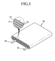
- FIG. 5 is an exploded perspective view of a rechargeable lithium battery according to one embodiment.
- a rechargeable lithium battery includes a jelly roll-type electrode assembly 10 and a case (not shown).
- the electrode assembly 10 may have a jelly roll shape formed by winding a negative electrode 11 and a positive electrode 12 and a separator 13 therebetween.
- the negative electrode 11, positive electrode 12, and separator 13 may be impregnated in an electrolyte (not shown).
- the negative electrode 11 includes a current collector and a negative active material layer disposed on the current collector.
- the current collector may be a copper foil, a nickel foil, a stainless steel foil, a titanium foil, a nickel foam, a copper foam, a polymer substrate coated with a conductive metal, or combinations thereof.
- the negative active material layer includes a negative active material, a binder, and optionally a conductive material.
- the negative active material includes a material that reversibly intercalates/deintercalates lithium ions, a lithium metal, an alloy of lithium metal, a material being capable of doping and dedoping lithium, or a transition metal oxide.
- the material that reversibly intercalates/deintercalates lithium ions includes carbon materials.
- the carbon material may be any generally-used carbon-based negative active material in a lithium ion rechargeable battery.
- Examples of the carbon material include crystalline carbon, amorphous carbon, and a combination thereof.
- the crystalline carbon may be non-shaped, or sheet, flake, spherical, or fiber shaped natural graphite or artificial graphite.
- the amorphous carbon may be a soft carbon (carbon obtained by sintering at a low temperature), a hard carbon, a mesophase pitch carbonized product, fired coke, and the like.
- the alloy of lithium metal includes lithium and a metal of Na, K, Rb, Cs, Fr, Be, Mg, Ca, Sr, Si, Sb, Pb, In, Zn, Ba, Ra, Ge, Al, or Sn.
- the material being capable of doping and dedoping lithium may include Si, SiO x (0 ⁇ x ⁇ 2), a Si-C composite, a Si-Q alloy (wherein Q is an element selected from the group consisting of an alkali metal, an alkaline-earth metal, Group 13 to 16 elements, a transition element, a rare earth element, and a combination thereof, and not Si), Sn, SnO 2 , a Sn-C composite, Sn-R (wherein R is an element selected from the group consisting of an alkali metal, an alkaline-earth metal, Group 13 to 16 elements, a transition element, a rare earth element, and combinations thereof and is not Sn), and the like.
- the Q and R may be an element of, Mg, Ca, Sr, Ba, Ra, Sc, Y, Ti, Zr, Hf, Rf, V, Nb, Ta, Db, Cr, Mo, W, Sg, Tc, Re, Bh, Fe, Pb, Ru, Os, Hs, Rh, Ir, Pd, Pt, Cu, Ag, Au, Zn, Cd, B, Al, Ga, Sn, In, Ti, Ge, P, As, Sb, Bi, S, Se, Te, Po, or a combination thereof.
- the transition metal oxide includes vanadium oxide, lithium vanadium oxide, and the like.
- the binder improves binding properties of the negative active material particles to one another and to a current collector.
- the binder include polyvinylalcohol, carboxylmethylcellulose, hydroxypropylcellulose, polyvinylchloride, carboxylated polyvinylchloride, polyvinylfluoride, an ethylene oxide-containing polymer, polyvinylpyrrolidone, polyurethane, polytetrafluoroethylene, polyvinylidene fluoride, polyethylene, polypropylene, a styrene-butadiene rubber, an acrylated styrene-butadiene rubber, an epoxy resin, nylon, and the like, but are not limited thereto.
- the conductive material improves electrical conductivity of a negative electrode.
- Any electrically conductive material can be used as a conductive agent, unless it causes a chemical change.
- the conductive material include a carbon-based material such as natural graphite, artificial graphite, carbon black, acetylene black, ketjen black, a carbon fiber, and the like; a metal-based material of a metal powder or a metal fiber including copper, nickel, aluminum, silver, and the like; a conductive polymer such as a polyphenylene derivative; or a mixture thereof.
- the positive electrode 12 includes a current collector and a positive active material layer disposed on the current collector.
- the current collector may be AI, but is not limited thereto.
- the positive active material layer may include a positive active material, a binder, and optionally a conductive material.
- the positive active material includes lithiated intercalation compounds that reversibly intercalate and deintercalate lithium ions.
- the positive active material may include a composite oxide including at least one selected from the group consisting of cobalt, manganese, and nickel, as well as lithium.
- the following lithium-containing compounds may be used:
- A is Ni, Co, Mn, or a combination thereof;
- R is Al, Ni, Co, Mn, Cr, Fe, Mg, Sr, V, a rare earth element, or a combination thereof;
- D is O, F, S, P, or a combination thereof;
- E is Co, Mn, or a combination thereof;
- Z is F, S, P, or a combination thereof;
- G is Al, Cr, Mn, Fe, Mg, La, Ce, Sr, V, or a combination thereof;
- Q is Ti, Mo, Mn, or a combination thereof;
- the compound may have a coating layer on the surface or be mixed with a compound having a coating layer.
- the coating layer may include at least one coating element compound selected from the group consisting of an oxide of a coating element, a hydroxide of a coating element, an oxyhydroxide of a coating element, an oxycarbonate of a coating element, and a hydroxyl carbonate of a coating element.
- the compounds for a coating layer can be amorphous or crystalline.
- the coating element for a coating layer may include Mg, Al, Co, K, Na, Ca, Si, Ti, V, Sn, Ge, Ga, B, As, Zr, or a mixture thereof.
- the coating layer can be formed in a method having no negative influence on properties of a positive active material by including these elements in the compound.
- the method may include any coating method such as spray coating, dipping, and the like but is not illustrated in more detail, since it is well-known to those who work in the related field.
- the binder improves binding properties of the positive active material particles to one another and to a current collector.
- the binder may include polyvinyl alcohol, carboxylmethyl cellulose, hydroxypropyl cellulose, diacetyl cellulose, polyvinylchloride, carboxylated polyvinylchloride, polyvinylfluoride, an ethylene oxide-containing polymer, polyvinylpyrrolidone, polyurethane, polytetrafluoroethylene, polyvinylidene fluoride, polyethylene, polypropylene, a styrene-butadiene rubber, an acrylated styrene-butadiene rubber, an epoxy resin, nylon, and the like, but are not limited thereto.
- the conductive material improves electrical conductivity of a negative electrode.
- Any electrically conductive material may be used as a conductive agent, unless it causes a chemical change.
- it may include natural graphite, artificial graphite, carbon black, acetylene black, ketjen black, carbon fiber, metal powder, metal fiber or the like such as copper, nickel, aluminum, silver or the like, or one or at least one kind of mixture of conductive material such as polyphenylene derivative or the like.
- the negative electrode 11 and positive electrode 12 may be fabricated in a method of mixing the active material, a conductive material, and a binder with an active material slurry and coating the slurry on a current collector, respectively.
- the solvent may include N-methylpyrrolidone and the like but is not limited thereto.
- the electrode-manufacturing method is well known and thus, is not described in detail in the present specification.
- the negative electrode 11 and positive electrode 12 are connected with a negative lead tab 14 and a positive lead tab 15, respectively, and the negative lead tab 14 and positive lead tab 15 are drawn out from the same side of an electrode assembly 10.
- the electrolyte includes a non-aqueous organic solvent and a lithium salt.
- the non-aqueous organic solvent serves as a medium of transmitting ions taking part in the electrochemical reaction of a battery.
- the non-aqueous organic solvent may include a carbonate-based, ester-based, ether-based, ketone-based, alcohol-based, or aprotic solvent.
- the carbonate-based solvent may include dimethyl carbonate (DMC), diethyl carbonate (DEC), dipropyl carbonate (DPC), methylpropyl carbonate (MPC), ethylpropyl carbonate (EPC), methylethyl carbonate (MEC), ethylene carbonate (EC), propylene carbonate (PC), butylene carbonate (BC), and the like
- the ester-based solvent may include methyl acetate, ethyl acetate, n-propyl acetate, 1,1-dimethylethyl acetate, methylpropionate, ethylpropionate, -butyrolactone, decanolide, valerolactone, mevalonolactone, caprolactone, and the like.
- the ether-based solvent may include dibutyl ether, tetraglyme, diglyme, dimethoxyethane, 2-methyltetrahydrofuran, tetrahydrofuran and the like.
- the ketone-based solvent may include cyclohexanone, and the like.
- the alcohol-based solvent may include ethanol, isopropylalcohol, and the like.
- the aprotic solvent include nitriles such as R-CN(wherein R is a C2 to C20 linear, branched, or cyclic hydrocarbon group, and may include a double bond, an aromatic ring, or an ether bond), amides such as dimethylformamide, dimethylacetamide, dioxolanes such as 1,3-dioxolane, sulfolanes, and the like.
- the non-aqueous organic solvent may be used singularly or in a mixture.
- the organic solvent is used in a mixture, its mixture ratio can be controlled in accordance with desirable performance of a battery.
- the carbonate-based solvent may include a mixture of a cyclic carbonate and a linear carbonate.
- the cyclic carbonate and the linear carbonate are mixed together in a volume ratio of about 1 : 1 to about 1 : 9 as an electrolyte, the electrolyte may have enhanced performance.
- the electrolyte may be prepared by further adding the aromatic hydrocarbon-based solvent to the carbonate-based solvent.
- the carbonate-based solvent and the aromatic hydrocarbon-based solvent are mixed together in a volume ratio of about 1 : 1 to about 30 : 1.
- the aromatic hydrocarbon-based organic solvent may be an aromatic hydrocarbon-based compound represented by the following Chemical Formula 1.
- R 1 to R 6 are each independently hydrogen, halogen, a C1 to C10 alkyl group, a C1 to C10 haloalkyl group, or a combination thereof.
- the aromatic hydrocarbon-based organic solvent may include benzene, fluorobenzene, 1,2-difluorobenzene, 1,3-difluorobenzene, 1,4-difluorobenzene, 1,2,3-trifluorobenzene, 1,2,4-trifluorobenzene, chlorobenzene, 1,2-dichlorobenzene, 1,3-dichiorobenzene, 1,4-dichiorobenzene, 1,2,3-trichlorobenzene, 1,2,4-trichiorobenzene, iodobenzene, 1,2-diiodobenzene, 1,3-diiodobenzene, 1,4-diiodobenzene, 1,2,3-triiodobenzene, 1,2,4-triiodobenzene, toluene, fluorotoluene, 1,2-difluorotoluene, 1,3-difluoro
- the non-aqueous electrolyte may further include vinylene carbonate or an ethylene carbonate-based compound represented by the following Chemical Formula 2 in order to improve cycle-life of a battery.
- R 7 and R 8 are each independently hydrogen, a halogen, a cyano group (CN), a nitro group (NO 2 ) or a C1 to C5 fluoroalkyl group, provided that at least one of R 7 and R 8 is a halogen, a cyano group (CN), a nitro group (NO 2 ) or a C1 to C5 fluoroalkyl group.
- Examples of the ethylene carbonate-based compound include difluoro ethylenecarbonate, chloroethylene carbonate, dichloroethylene carbonate, bromoethylene carbonate, dibromoethylene carbonate, nitroethylene carbonate, cyanoethylene carbonate, fluoroethylene carbonate, and the like.
- the use amount of the vinylene carbonate or the ethylene carbonate-based compound for improving cycle life may be adjusted within an appropriate range.
- the lithium salt is dissolved in the non-aqueous solvent and supplies lithium ions in a rechargeable lithium battery, and basically operates the rechargeable lithium battery and improves lithium ion transfer between positive and negative electrodes.
- the lithium salt include LiPF 6 , LiBF 4 , LiSbF 6 , LiAsF 6 , LiC 4 F 9 SO 3 , LiClO 4 , LiAlO 2 , LiAlCl 4 , LiN(C x F 2x+1 SO 2 )(C y F 2y+1 SO 2 ) (wherein, x and y are natural numbers), LiCl, Lil, LiB(C 2 O 4 ) 2 (lithium bis(oxalato) borate, LiBOB), or a combination thereof which is used as a supporting electrolytic salt.
- the lithium salt may be used in a concentration of about 0.1 to about 2.0M. When the lithium salt is included within the above concentration range, it may electrolyte performance and lithium ion mobility due to optimal electrolyte
- the separator 13 plays a role of separating a negative electrode 112 from a positive electrode 114 and providing a path for lithium ions and includes a porous substrate and a coating layer as described above.
- the separator is the same as described.
- SBR styrene-butadiene rubber
- the slurry was coated to be 16 ⁇ m thick on both sides of a polyethylene substrate and dried at a drying rate of 50%/min (as measured by the gravimetric method), fabricating a separator having a about 3 ⁇ m-thick coating layer.
- PVdF polyvinylidene fluoride
- NMP N-methyl-2-pyrrolodone
- SBR styrene-butadiene rubber
- a separator was fabricated according to the same method as Example 1 except for using no urethane emulsion.
- a separator was fabricated according to the same method as Example 1 except for adding no styrene-butadiene rubber (SBR).
- SBR styrene-butadiene rubber
- a separator was fabricated according to the same method as Example 2 except for performing the drying at a drying rate of 20%/min (as measured by the gravimetric method).
- FIG. 6 is the SEM photograph of the separator according to Example 2.
- the separator according to Example 2 had a coating layer having a predetermined thickness on both sides thereof.
- FIG. 7 is a SEM photograph showing the surface of the coating layer on the separator according to Example 2
- FIG. 8 is a SEM photograph showing the surface of the coating layer on the separator according to Comparative Example 3.
- the separator according to Example 2 was mapping-analyzed to examine distribution of a styrene-butadiene rubber (SBR), a particulate polymeric binder.
- SBR styrene-butadiene rubber
- the mapping analysis was performed by an energy dispersive X-Ray spectroscopy (EDS) method.
- the separator was fabricated according to the same method as Example 2 except for using the alumina particulates in Example 2,.
- SBR styrene-butadiene rubber
- FIG. 9 is a drawing that shows mapping analysis of fluorine atom at the cross section of the coating layer of the separator.
- the top (surface) of the coating layer included less fluorine atoms than the bottom (near to a polyethylene substrate) of the coating layer.
- the analysis result shows that styrene-butadiene rubbers (SBR) including no fluorine atom more exist at the surface of a coating layer, since more styrene-butadiene rubbers (SBR) move toward the surface during the drying of the coating layer.
- SBR styrene-butadiene rubbers
- the separators according to Examples 1 and 2 and Comparative Examples 1 to 3 were heat-treated in a 130° C convention oven for 10 minutes and cooled down to room temperature. The separators were measured regarding shrinkage ratio before and after the heat treatment.
- the separators according to Examples 1 and 2 had a similar thermal shrinkage ratio to the ones according to Comparative Examples 1 to 3. Accordingly, a polymeric binder, that is, a urethane emulsion or styrene-butadiene rubber (SBR) included in Examples 1 and 2 turned out to have no influence on heat resistance.
- SBR styrene-butadiene rubber
- a positive active material slurry was prepared by mixing LiCoO 2 as a positive active material, polyvinylidene fluoride (PVDF) as a binder, and carbon as a conductive agent in a weight ratio of 92:4:4 and dispersing the mixture in N-methyl-2-pyrrolidone.
- the slurry was coated on a 20 ⁇ m-thick aluminum foil, dried, and compressed, fabricating a positive electrode.
- a negative active material slurry was prepared by mixing artificial graphite as a negative active material, a styrene-butadiene rubber as a binder, and carboxylmethylcellulose as a thickener in a weight ratio of 96:2:2 and dispersing the mixture into water. This slurry was coated on a 155 ⁇ m-thick copper foil, dried, and compressed, fabricating a negative electrode.
- the positive and negative electrodes and the separator according to Example 1 were used to fabricate a pouch-type rechargeable lithium battery cell.
- An electrolyte was prepared by mixing ethyl carbonate (EC) /ethylmethylcarbonate (EMC) / diethylcarbonate (DEC) (a volume ratio of 3/5/2) and including LiPF 6 in a concentration of 1.3M.
- a rechargeable lithium battery cell was fabricated according to the same method as Example 3 except for using the separator according to Example 2 instead of the separator according to Example 1.
- a rechargeable lithium battery cell was fabricated according to the same method as Example 3 except for using the separator according to Comparative Example 1 instead of the separator according to Example 1.
- a rechargeable lithium battery cell was fabricated according to the same method as Example 3 except for using the separator according to Comparative Example 2 instead of the separator according to Example 1.
- a rechargeable lithium battery cell was fabricated according to the same method as Example 3 except for using the separator according to Comparative Example 3 instead of the separator according to Example 1.
- the rechargeable lithium battery cells according to Examples 3 and 4 and Comparative Examples 3 to 5 were decomposed and evaluated regarding adhesive property of the separators to positive and negative electrodes.
- the adhesive property evaluation was measured regarding peeling strength using a universal test machine (UTM).
- the rechargeable lithium battery cells according to Examples 3 and 4 had improved adherence of the separators to electrodes compared with the ones according to Comparative Examples 3 to 5.
- the rechargeable lithium battery cells according to Examples 3 and 4 and Comparative Examples 3 to 5 were constant-current-charged at a 0.2C rate up to a voltage of 4.2V at 25° C and constant-voltage-charged up to a current of 0.01C while maintaining a voltage of 4.2V.
- the rechargeable lithium battery cells were discharged with a constant current of 0.2C up to a voltage of 3.05V during the discharge (formation step).
- the rechargeable lithium battery cells were constant current charged at a 0.5C rate up to a voltage of 4.2V at 25° C and constant voltage charged up to a current of 0.01C while maintaining 4.2V. Then, the rechargeable lithium battery cells were discharged with a constant current of 0.5C up to a voltage of 3.0V The charge and discharge cycle was 30 times repeated.
- the rechargeable lithium battery cells according to Examples 3 and 4 had higher charge and discharge efficiency and capacity retention than the ones according to Comparative Examples 3 to 5. The reason is that the rechargeable lithium battery cells according to Examples 3 and 4 had improved adhesive property of a separator to an electrode.
- a separator used for the rechargeable lithium battery cells according to Examples 3 and 4 had a similar thermal shrinkage ratio to one for the rechargeable lithium battery cells according to Comparative Examples 3 to 5 but better adherence to an electrode, improving charge and discharge efficiency and capacity retention of the rechargeable lithium battery cells.
Landscapes
- Chemical & Material Sciences (AREA)
- Chemical Kinetics & Catalysis (AREA)
- Electrochemistry (AREA)
- General Chemical & Material Sciences (AREA)
- Engineering & Computer Science (AREA)
- Inorganic Chemistry (AREA)
- Manufacturing & Machinery (AREA)
- Materials Engineering (AREA)
- Composite Materials (AREA)
- Ceramic Engineering (AREA)
- Cell Separators (AREA)
- Battery Electrode And Active Subsutance (AREA)
- Secondary Cells (AREA)
Abstract
a substrate;
a coating layer disposed on at least one surface of the substrate, wherein the coating layer comprises at least one polymeric binder, wherein the amount of the polymeric binder present at a surface portion of the coating layer is greater than at an inner portion of the coating layer.
Description
- A separator, a method of manufacturing the same, and a rechargeable lithium battery including the separator are related.
- A non-aqueous rechargeable lithium battery includes a separator made of a porous insulating film and interposed between positive and negative electrodes, and the pores of the film are impregnated by an electrolyte including a lithium salt dissolved therein. The non-aqueous rechargeable lithium battery has excellent high-capacity and high energy density characteristics.
- However, when the positive and negative electrodes therein are repetitively contracted and expanded during the charge and discharge cycles or exothermic heat due to abnormal operation of a battery becomes large, battery temperature may be abruptly increased. In this case, a separator may be abruptly contracted or destroyed, short-circuit of electrodes may occur.
- Accordingly, a method of coating heat resistance inorganic particles along with a binder on at least one side of the separator in order to secure battery stability has been suggested. However, when a content of the heat resistance inorganic particles becomes large, the binder is relatively less included, deteriorating adhesive property of the separator to the electrode.
- The present invention provides a separator for a rechargeable lithium battery as defined in any of
claims 1 to 11 and a method for producing said separator as defined in any ofclaims 12 to 15. - One embodiment provides a separator being capable of improving adhesive property with an electrode while securing stability of a battery.
- Another embodiment provides a method of manufacturing the separator.
- Yet another embodiment provides a rechargeable lithium battery including the separator.
- According to one embodiment, provided is a separator that includes a substrate and a coating layer disposed on at least one side of the substrate including a polymeric binder, wherein an amount of the polymeric binder that is present at a surface portion of the coating layer is greater than that of the polymeric binder that is present inside of the coating layer.
- The polymeric binder may preferably include polymeric binders having a different particle size.
- The polymeric binder may preferably include a first polymeric binder having a first average particle diameter and a second polymeric binder having a second average particle diameter of less than or equal to 80% of the first average particle diameter.
- The first and second polymeric binders may preferably be an emulsion, suspension or colloidal polymeric binder. In a preferred embodiment the liquid phase of the above binders comprises water, preferably the liquid phase essentially consists of water, e.g. 95%-100% by weight, preferably the liquid phase consists of water. In a preferred embodiment the polymeric binder is present in the liquid at a concentration of between 20% and 50% by weight of the total weight of polymer and liquid phase, preferably between 30% and 40% by weight.
- The polymeric binder, preferably an emulsion polymeric binder, may preferably include a diene-based polymer, an acrylate-based polymer, a styrene-based polymer, a urethane-based polymer, a polyolefin-based polymer, or a combination thereof.
- The polymeric binder, preferably an emulsion polymeric binder, may preferably include a styrene-butadiene rubber, an acrylated styrene-butadiene rubber, an acrylonitrile-butadiene rubber, an acrylonitrile-butadiene-styrene rubber, an acrylic rubber, a butyl rubber, a fluorine rubber, polytetrafluoroethylene, polyethylene, polypropylene, ethylene propylene copolymer, polyethyleneoxide, polyvinylpyrrolidone, polyepichlorohydrine, polyphosphazene, polyacrylate, polyacrylonitrile, polystyrene, ethylene propylene diene copolymer, polyvinylpyridine, chlorosulfonated polyethylene, latex, a polyester resin, an acrylic resin, a phenolic resin, an epoxy resinpolyvinylalcohol, carboxylmethylcellulose, hydroxypropylmethylcellulose, hydroxypropylcellulose, diacetylcellufose, or a combination thereof.
- The binder may preferably comprise a first polymeric binder and a second polymeric binder, optionally the first polymeric binder may preferably be included in a greater amount than the second polymeric binder. The first and second polymeric binders are preferably independently selected from the binders discussed above.
- The first and second polymeric binder may preferably be respectively included in an amount of about 70 to 99 parts by weight and about 1 to 30 parts by weight based on the total weight of the polymeric binder.
- The polymeric binder may preferably include a third solvent-soluble polymeric binder and a fourth polymeric binder, preferably an emulsion polymeric binder, wherein the third polymeric binder is soluble in a solvent which the fourth polymeric binder is insoluble.
- The solvent-soluble third polymeric binder may preferably include polyvinylidene fluoride (PVdF), polyvinylidene fluoride-hexafluoropropylene (PVdF-co-HFP), polyvinylidene fluoride-trichloroethylene, polyvinylpyrrolidone, polyethyleneoxide (PEO), polyacrylonitrile (PAN), polyimide (PI), polyamic acid (PAA), polyamideimide (PAI), aramid, polyvinylacetate (PVA), an ethylenevinylacetate copolymer, an ethyleneethylacrylate copolymer, polymethylmetaacrylate (PMMA), polyvinylether (PVE), carboxylmethylcellulose, polyacrylic acid, polyvinyl alcohol, or a combination thereof.
- The fourth polymeric binder, preferably an emulsion polymeric binder, may preferably include a diene-based polymer, an acrylate-based polymer, a styrene-based polymer, a urethane-based a polymer, a polyolefin-based polymer, or a combination thereof.
- The fourth polymeric binder, preferably an emulsion polymeric binder, may preferably include a styrene-butadiene rubber, an acrylated styrene-butadiene rubber, an acrylonitrile-butadiene rubber, an acrylonitrile-butadiene-styrene rubber, an acrylic rubber, a butyl rubber, a fluorine rubber, polytetrafluoroethylene, polyethylene, polypropylene, ethylene propylene copolymer, polyethyleneoxide, polyvinylpyrrolidone, polyepichlorohydrine, polyphosphazene, polyacrylate, polyacrylonitrile, polystyrene, ethylene propylene diene copolymer, polyvinylpyridine, chlorosulfonated polyethylene, latex, a polyester resin, an acrylic resin, a phenolic resin, an epoxy resinpolyvinylalcohol, carboxylmethylcellulose, hydroxypropylmethylcellulose, hydroxypropylcellulose, diacetylcellulose, or a combination thereof.
- The solvent-soluble polymeric binder may preferably be more included than the emulsion polymeric binder.
- The solvent-soluble polymeric binder and the emulsion polymeric binder may preferably be respectively included in an amount of about 70 to 99 parts by weight and about 1 part by weight to 30 parts by weight based on the total weight of the polymeric binder.
- The polymeric binder may preferably be included in an amount of about 1 to 30 parts by weight based on 100 parts by weight of the inorganic compound.
- The inorganic compound may preferably include metal oxide, semi-metal oxide, metal fluoride, metal hydroxide, or a combination thereof.
- The inorganic compound may preferably include Al2O3, SiO2, TiO2, SnO2, CeO2, MgO, NiO, CaO, ZnO, ZrO2, Y2O3, SrTiO3, BaTiO3, Mg(OH)2, or a combination thereof.
- The porous substrate may preferably include a glass fiber, polyester, TEFLON (tetrafluoroethylne), polyolefin, polytetrafluoroethylene (PTFE), or a combination thereof.
- According to another embodiment, provided is a method of manufacturing the separator including applying a slurry including an inorganic compound and a polymeric binder on at least one side of a porous substrate and drying the slurry at a rate of about 30 to 70%/min.
- The drying rate may preferably be in a rage of about 40 to 60%/min. In a preferred embodiment, the drying rate is measured by the gravimetric method.
- According to another embodiment, provided is a rechargeable lithium battery that includes a positive electrode including a positive active material, a negative electrode including a negative active material, an electrolyte, and the separator interposed between the positive electrode and the negative electrode.
- The coating layer may preferably have a first side in contact with either one of the positive and negative electrodes and a second side in contact with the porous substrate.
- The first side may preferably include the polymeric binder more than the second side.
- Therefore, the separator may have better adhesive property to the electrode and thus, improve characteristics of a battery as well as secure stability of the battery.
-
-
FIG. 1 is a cross-sectional view showing a separator for a rechargeable lithium battery according to one embodiment. -
FIG. 2 is an enlarged schematic view showing a coating layer of the separator illustrated inFIG. 1 . -
FIGS. 3 and 4 are schematic views respectively showing a method of forming a coating layer on the separator ofFIG. 1 . -
FIG. 5 is an exploded perspective view showing a rechargeable lithium battery according to one embodiment. -
FIG. 6 is a SEM photograph showing the separator according to Example 2. -
FIG. 7 is a SEM photograph showing the surface of the coating layer on the separator according to Example 2. -
FIG. 8 is a SEM photograph showing the surface of the coating layer on the separator according to Comparative Example 3. -
FIG. 9 is a drawing showing the mapping analysis of fluorine atom at the cross section of the coating layer of the separator. - The present invention will be described more fully hereinafter, in which exemplary embodiments of the invention are shown. As those skilled in the art would realize, the described embodiments may be modified in various different ways, all without departing from the spirit or scope of the present invention.
- Hereinafter, referring to drawings, a separator for a rechargeable lithium battery according to one embodiment is described.
-
FIG. 1 is a cross-sectional view of a separator for a rechargeable lithium battery according to one embodiment. - The
separator 13 includes a substrate, which is preferably porous, 23 and acoating layer 33 disposed on one side or both sides of theporous substrate 23. - The
porous substrate 23 may preferably include, for example a glass fiber, polyester, TEFLON (tetrafluoroethylne), polyolefin, polytetrafluoroethylene (PTFE), or a combination thereof. The polyolefin may preferably include, for example polyethylene, polypropylene, and the like. - The
porous substrate 23 may preferably be a single layer or a multilayer such as a mixed multilayer, for example a polyethylene/polypropylene double separator, a polyethylene/polypropylene/polyethylene triple separator, a polypropylene/polyethylene/polypropylene triple separator, and the like. - The
coating layer 33 preferably includes an inorganic compound and a polymeric binder. - The inorganic compound is preferably a ceramic material being capable of improving heat resistance, and may preferably include, for example metal oxide, semi-metal oxide, metal fluoride, metal hydroxide, or a combination thereof. The inorganic compound may preferably include for example Al2O3, SiO2, TiO2, SnO2, CeO2, MgO, NiO, CaO, ZnO, ZrO2, Y2O3, SrTiO3, BaTiO3, Mg(OH)2, or a combination thereof.
- The inorganic compound may improve heat resistance of a coating layer and thus, prevent abrupt contraction or transformation of the separator according to temperature increase.
- The inorganic compound may preferably be a particle and for example, have a particle diameter ranging from about 1nm to 1000nm. The particle diameter may preferably be in a range of about 10nm to 800nm and specifically, about 200 to 600nm within the range. The inorganic compound having a particle diameter within the range may apply appropriate strength to the
coating layer 33. - The polymeric binder may play a role of fixing the inorganic compound on a
porous substrate 23 and simultaneously, may provide strong adherence to adhere to theporous substrate 23 at one side of thecoating layer 33 and to the electrode (not shown) at the other side of the coating layer. - Herein, the amount of the polymeric binder is greater at the surface of the
coating layer 33 than the amount of the polymeric binder inside thecoating layer 33. Herein, the surface of thecoating layer 33 may preferably be a portion contacting with the electrode. - In a preferred embodiment of the present invention the surface portion comprises between about 50% and 25% of the thickness of the coating layer, preferably about 30% to 40%, the remainder being the inner portion of the coating layer.
- In an embodiment of the present invention the coating layer, post drying, is preferably between about 1.5 and 5 microns in thickness, more preferably between about 2 and 4 microns.
-
FIG. 2 is an enlarged schematic view showing a coating layer of the separator illustrated inFIG. 1 . - In
FIG. 2 , where the polymeric binder is more included in thecoating layer 33 is marked dark, while where the polymeric binder is relatively less included in thecoating layer 33 is marked light, for better comprehension and ease of description. - Referring to
FIG. 2 , the polymeric binder is more included at the surface of thecoating layer 33 than the inside of thecoating layer 33. When the polymeric binder is more included at the surface of thecoating layer 33, the separator may be better adhered to the electrode. - Accordingly, since the
coating layer 33 includes the polymeric binder at the surface without decreasing the inorganic compound all over the coating layer, the separator having thecoating layer 33 may be well adhered to an electrode. Accordingly, thecoating layer 33 may secure heat resistance and adherence simultaneously. - Hereinafter, a method of forming the
coating layer 33 is illustrated referring to drawings. -
FIGS. 3 and 4 are schematic views respectively showing a method of forming a coating layer of the separator ofFIG. 1 . - According to an embodiment of a method of forming a coating layer, referring to
FIG. 3 along withFIG. 1 , a slurry including an inorganic compound (not shown), a firstpolymeric binder 33a having a first average particle diameter, and a secondpolymeric binder 33b having a second average particle diameter of less than or equal to about 80% of the first average particle diameter, specifically, less than or equal to about 50% thereof is coated on one side of aporous substrate 23. - In a preferred embodiment of the present invention the average particle diameter of the second polymeric binder is between about 80% and 20% of the average particle diameter of the first polymeric binder, more preferably between about 50% and 25%, and more preferably between about 40% and 30%.
- Herein, the first average particle diameter may preferably be in a range of about 50nm to about 500 nm, and the second average particle diameter may preferably be in a range of about 20nm to about 400 nm.
- In an embodiment of the present invention the first average particle diameter may preferably be in a range of about 60nm to about 200 nm, more preferably about 70nm to about 150nm and more preferably about 75nm to about 100nm. In an embodiment of the present invention the second average particle diameter may preferably be in a range of about 25nm to about 200 nm, more preferably about 25nm to about 80nm and more preferably about 27nm to about 50nm. When the first and second polymeric binders have an average particle diameter within the above ranges, a polymer emulsion may preferably have appropriate viscosity and sufficient adhesive property.
- In an embodiment of the present invention the first
polymeric binder 33a is a main polymeric binder fixing the inorganic compound on the substrate, preferably porous, 23, and the secondpolymeric binder 33b is an auxiliary polymeric binder increasing adhesive property. The first and secondpolymeric binders polymeric binders - As the slurry is dried, the polymeric binder and the inorganic compound in the coating layer may move toward the surface of the coating layer due to a thermal convection, since the surface of the coating layer may be dried earlier than the inside. The second
polymeric binder 33b having a smaller average particle diameter may more easily move toward the surface of the coating layer. Accordingly, the first and second polymeric binders are more included at the surface and may increase the surface adhesive property of thecoating layer 33. - In an embodiment of the present invention the first
polymeric binder 33a and the secondpolymeric binder 33b may preferably be an emulsion-type, suspension or colloidal polymeric binder and also, the same or different. The polymeric binder, preferably an emulsion polymeric binder, may preferably include for example a diene-based polymer, an acrylate-based polymer, a styrene-based polymer, an urethane-based polymer, a polyolefin-based polymer, or a combination thereof, for example a styrene-butadiene rubber, an acrylated styrene-butadiene rubber, an acrylonitrile-butadiene rubber, an acrylonitrile-butadiene-styrene rubber, an acrylic rubber, a butyl rubber, a fluorine rubber, polytetrafluoroethylene, polyethylene, polypropylene, ethylene propylene copolymer, polyethyleneoxide, polyvinylpyrrolidone, polyepichlorohydrine, polyphosphazene, polyacrylate, polyacrylonitrile, polystyrene, ethylene propylene diene copolymer, polyvinylpyridine, chlorosulfonated polyethylene, latex, a polyester resin, an acrylic resin, a phenolic resin, an epoxy resin, polyvinylalcohol, carboxylmethylcellulose, hydroxypropylmethylcellulose, hydroxypropyfcellulose, diacetylcellulose, a polyurethane, or a combination thereof. - The emulsion-type polymeric binder may preferably be prepared by emulsion polymerization or a phase inversion method using a polymerizable monomer. The emulsion polymerization method and phase inversion method have no particular limited conditions.
- In a preferred embodiment of the present invention the first polymeric binder is selected from the group consisting of a styrene-butadiene rubber, an acrylated styrene-butadiene rubber, an acrylonitrile-butadiene rubber, and an acrylonitrile-butadiene-styrene rubber or a combination thereof. In a preferred embodiment of the present invention the second polymeric binder is a urethane-based polymer, preferably polyurethane.
- The polymerizable monomer may preferably include, for example an ethylenic unsaturated carbonic acid alkyl ester such as methyl (meth)acrylate, butyl (meth)acrylate, ethyl (meth)acrylate, hexyl(meth)acrylic acid-2-ethyl, and the like; an ethylenic unsaturated monomer having a cyano group such as acrylonitrile, metacrylonitrile, fumaronitrile, a -chloro acrylonitrile, α - cyanoethylacrylonitrile, and the like; a conjugated diene monomer such as 1,3-butadiene, isoprene, 2,3-dimethyl-1, 3-butadiene, 2-ethyl-1, 3-butadiene, 1,3-pentadiene, chloroprene, and the like; ethylenic unsaturated carboxylic acid and a salt thereof such as acrylic acid, methacrylic acid, maleic acid, fumaric acid, citraconic acid, and the like; an aromatic vinyl monomer such as styrene, alkyl styrene, vinyl naphthalene, and the like; a fluorine alkyl vinyl ether such as fluorine ethyl vinyl ether, and the like; a non-conjugated diene monomer such as vinyl pyridine; α -olefin such as ethylene, propylene, and the like; an ethylenic unsaturated amide monomer such as (meth)acryl amide; a sulfonic acid-based unsaturated monomer such as acryl amide methyl propane sulfonic acid, styrene sulfonic acid, and the like; and the like.
- In addition, the polymerizable monomer may preferably include a polymerizable monomer having a cross-linking functional group. The cross-linking functional group is a functional group working as a cross-linking point when the polymeric binder is cross-linked and may preferably include, for example, a hydroxyl group, a glycidyl group, an amino group, an N-methanol group, a vinyl group, and the like.
- The polymerizable monomer including the cross-linking functional group may preferably include, for example hydroxy ester of ethylenic unsaturated carboxylic acid such as (meth) acrylic acid hydroxy propyl, (meth) acrylic acid hydroxy ethyl, and the like; glycidyl ester of ethylenic unsaturated carboxylic acid such as glycidyl(meth) acrylate, and the like; amino ester of ethylenic unsaturated carboxylic acid such as dimethyl amino ethyl(meth) acrylate, and the like; a methylol group-containing ethylenic unsaturated amide such as N-methylol(meth) acryl amide, N,N-dimethylol(meth) acryl amide, and the like; a monomer including at least two vinyl groups such as ethylene di(meth) acrylate, divinyl benzene, and the like.
- The polymerizable monomer including the cross-linking functional group may preferably be included in an amount of less than or equal to about 5wt%, specifically, less than or equal to about 2wt% based on the total weight of the polymerizable monomer.
- In an embodiment of the present invention the coating layer comprises a third polymeric binder and a fourth polymeric binder, wherein the third polymeric binder is soluble in a solvent which the fourth polymeric binder is insoluble in and the amounts of the third or fourth polymeric binders present at a surface portion of the coating layer are greater than at an inner portion of the coating layer.
- In a preferred embodiment of the present invention the fourth polymeric binder is an emulsion, suspension or colloidal polymeric binder. In a preferred embodiment the liquid phase of the above binders comprises water, preferably the liquid phase essentially consists of water, e.g. 95%-100% by weight, preferably the liquid phase consists of water. In a preferred embodiment the polymeric binder is present in the liquid at a concentration of between 20% and 50% by weight of the total weight of polymer and liquid phase, preferably between 30% and 40% by weight.
- According to another embodiment of a method of forming a coating layer, referring to
FIG. 4 along withFIG. 1 , slurry including an inorganic compound (not shown), a solvent-soluble polymeric binder as a thirdpolymeric binder 33c, a polymeric binder, preferably an emulsion polymeric binder, as afourth polymeric binder 33d, and a solvent may be coated on one side of theporous substrate 23. - The third
polymeric binder 33c is preferably a solvent-soluble polymeric binder and is preferably a main polymeric binder. The solvent-soluble polymeric binder is preferably a polymeric binder dissoluble in a solvent, and may preferably include, for example polyvinylidene fluoride (PVdF), polyvinylidene fluoride-hexafluoropropylene (PVdF-co-HFP), polyvinylidene fluoride-trichloroethylene, polyvinylpyrrolidone, polyethyleneoxide (PEO), polyacrylonitrile (PAN), polyimide (PI), polyamic acid (PAA), polyamideimide (PAI), aramid, polyvinylacetate (PVA), an ethylenevinylacetate copolymer, an ethyleneethylacrylate copolymer, polymethylmetaacrylate (PMMA), polyvinylether (PVE), carboxylmethylcellulose, polyacrylic acid, polyvinyl alcohol, or a combination thereof. - The
fourth polymeric binder 33d is preferably an emulsion polymeric binder, which exists as a particulate in a solvent, and the fourth polymeric binder is an auxiliary polymeric binder. The fourth polymeric binder, preferably an emulsion polymeric binder, may preferably include any of the above-described first or second polymeric binders, for example a diene-based polymer, an acrylate-based polymer, a styrene-based polymer, an urethane-based polymer, a polyolefin-based polymer, or a combination thereof, and for example a styrene-butadiene rubber, an acrylated styrene-butadiene rubber, an acrylonitrile-butadiene rubber, an acrylonitrile-butadiene-styrene rubber, an acrylic rubber, a butyl rubber, a fluorine rubber, polytetrafluoroethylene, polyethylene, polypropylene, ethylene propylene copolymer, polyethyleneoxide, polyvinylpyrrolidone, polyepichlorohydrine, polyphosphazene, polyacrylate, polyacrylonitrile, polystyrene, ethylene propylene diene copolymer, polyvinylpyridine, chlorosulfonated polyethylene, latex, a polyester resin, an acrylic resin, a phenolic resin, an epoxy resinpolyvinylalcohol, carboxylmethylcellulose, hydroxypropylmethylcellulose, hydroxypropylcellulose, diacetylcellulose, a polyurethane, or a combination thereof. - In a preferred embodiment of the present invention the third polymeric binder is selected from the group consisting of polyvinylidene fluoride (PVdF), polyvinylidene fluoride-hexafluoropropylene (PVdF-co-HFP), polyvinylidene fluoride-trichloroethylene, and polyvinylpyrrolidone or a combination thereof. In a preferred embodiment of the present invention the fourth polymeric binder is selected from the group consisting of a styrene-butadiene rubber, an acrylated styrene-butadiene rubber, an acrylonitrile-butadiene rubber, and an acrylonitrile-butadiene-styrene rubber, a polyurethane, or a combination thereof.
- As the third polymeric binder is soluble in a solvent which the fourth polymeric binder is not soluble in, although certain of the above preferred embodiments of these polymers do overlap, these polymeric binders cannot be the same, i.e. the third polymeric binder must be soluble in a solvent in which the fourth polymeric binder is not.
- The third
polymeric binder 33c and thefourth polymeric binder 33d may preferably be respectively included in an amount of about 70 to 99 parts by weight and about 1 to 30 parts by weight based on the total weight of the polymeric binder. In a preferred embodiment of the present invention the third and fourth polymeric binders are included in an amount of about 85 to 99 parts by weight and about 1 to 15 parts by weight, respectively, based on the total weight of the binder polymer, more preferably about 90 to 98 parts by weight and about 2 to 10 parts by weight. These weights are based on the dry weight of the polymeric binders. - When the third
polymeric binder 33c and thefourth polymeric binder 33d are included within the range, the coating layer may be sufficiently adhered to a porous substrate, and while the separators may be prevented from being stuck together due to excessive stickiness. - As the slurry is dried, the solvent may move toward the surface of the coating layer due to a thermal convection, since the surface of the coating layer may be dried earlier than the inside thereof. Herein, the polymeric binder may move toward the surface of the coating layer, along with the solvent. Herein, the fourth polymeric binder existing as particulates in a solvent may more easily move to the surface. Accordingly, the third and fourth polymeric binders may exist more at the surface than the inside and increase adhesive property of the
coating layer 33 at the surface. - Furthermore, a solvent-soluble third polymeric binder along with the fourth polymeric binder exists at the surface of the
coating layer 33 and may increase adhesive property of the coating layer to a negative active material layer including an emulsion polymeric binder such as a styrene-butadiene rubber as a binder as well as to a positive active material layer including a solvent-soluble polymeric binder such as polyvinylidene fluoride (PVdF) as a binder. Accordingly, the separator having thecoating layer 33 may have high adhesive property to both positive and negative electrodes. - The polymeric binder may preferably be included in an amount of about 1 to 30 parts by weight based on 100 parts by weight of the inorganic compound. The first and second polymeric binders may preferably be included in a total amount of about 2 to 10 parts by weight, more preferably in an amount of about 2.5 to 7.5 parts by weight. The third and fourth polymeric binders may preferably be included in a total amount of about 5 to 25 parts by weight, more preferably in an amount of about 10 to 20 parts by weight.
- When the binder is included within the above ranges, the coating layer may preferably improve adhesive property of the separator to a porous substrate and an electrode and while may not close pores in the porous substrate and maintain ion conductivity.
- Hereinafter, a method of fabricating the separator is illustrated.
- According to one embodiment, the method of manufacturing a separator may include applying slurry including an inorganic compound and a polymeric binder on at least one side of a substrate, preferably porous, and drying the slurry to form a coating layer.
- As described above, the polymeric binder may preferably be a mixture of the polymeric binders having a different particle size or a mixture of a third solvent-soluble polymeric binder and a fourth polymeric binder, preferably emulsion polymeric binder.
- When the binder contains a third solvent-soluble binder, it is preferably pre-mixed with a solvent prior to formation of the slurry containing the third and fourth polymeric binders. Preferably, the solvent is selected from the group consisting of N-methyl-2-pyrrolodone, dimethyl formamide, dimethyl acetamide, tetramethyl urea, triethyl phosphate, dimethyl sulfoxide, acetone, methyl ethyl ketone, methyl isobutyl ketone, cyclohexanone, or a combination thereof
- The slurry may preferably be dried in a method of, for example, hot air drying, infrared drying, and the like at a drying rate of about 30 to 70%/min.
- Herein, the drying rate refers to a speed of drying about 30 to 70% of a solvent in the slurry per minute based on the original amount of solvent present in slurry applied to form the coating layer. This may be calculated based on drying temperature, the amount of provided air, the amount of discharged air, a air speed, a heating method, and the like.
- The drying temperature may depend on a solvent and a drying atmosphere. The drying temperature may preferably generally range from about 45°C to about 110°C, preferably about 50°C to about 90°C, and more preferably about 60°C to about 80°C. When the drying is performed in the temperature, it is possible to dry a solvent and prevent the porous substrate from contracting.
- When the drying rate is within the range, the polymeric binder sufficiently moves toward the surface of the coating layer as aforementioned, and the surface of the coating layer may be prevented from crack or transformation due to rapid drying.
- The drying may preferably be performed at a rate of about 40 to 60%/min within the range, more preferably about 45 to 55%/min.
- Hereinafter, a rechargeable lithium battery including the separator is described.
- The rechargeable lithium battery may be classified as a lithium ion battery, a lithium ion polymer battery, and a lithium polymer battery according to the presence of a separator and the kind of an electrolyte used therein. The rechargeable lithium battery may have a variety of shapes and sizes and thus, may include a cylindrical, prismatic, coin, or pouch-type battery and a thin film type or a bulky type in size. The structure and fabricating method for a lithium ion battery pertaining to the present invention are well known in the art.
- The separator has a coating layer including a polymeric binder and thus, improved adherence and particularly, may be stably adhered to an electrode and thus, have no gap due to detachment from the electrode but be firmly fixed together.
- The average particle size (D50) of the polymeric binders used in the present invention, may preferably be measured using a laser diffraction light scattering diameter distribution measurement method. Preferably, a Mastersizer 2000 (Malvern Instruments) laser diffractometer is used. The Mastersizer 2000 calculates the particle size distribution (and therefore the 50th percentile of this distribution - the D50) by volume as a default setting. This is the primary result calculation using Mie theory. When carrying out the measurement of the above parameters using a Mastersizer 2000 preferably a dispersant is used, preferably water (preferably 99.9% purity) is used as the dispersant. If water is used as a dispersant, the relative refractive index of water is taken as between 1.30 and 1.35, preferably 1.33. The particle refractive index is dependent on the polymeric binder being used and these values are readily available in the art. For example, for a styrene-butadiene rubber the refractive index is preferably between 1.8 and 3.90 and for a polyurethane the refractive index is preferably between 1.20 and 2.50. Preferably, sonication for between 1 and 3 minutes, preferably 2 minutes, to aid dispersion is carried out. Sonication is preferably carried out between 1kHz and 10KHz, preferably at 5kHz. The absorption index value is preferably set between 0.5 and 1.5, preferably a value of 1.0 is used.
-
FIG. 5 is an exploded perspective view of a rechargeable lithium battery according to one embodiment. - Referring to
FIG. 5 , a rechargeable lithium battery includes a jelly roll-type electrode assembly 10 and a case (not shown). - The
electrode assembly 10 may have a jelly roll shape formed by winding anegative electrode 11 and apositive electrode 12 and aseparator 13 therebetween. Thenegative electrode 11,positive electrode 12, andseparator 13 may be impregnated in an electrolyte (not shown). - The
negative electrode 11 includes a current collector and a negative active material layer disposed on the current collector. - The current collector may be a copper foil, a nickel foil, a stainless steel foil, a titanium foil, a nickel foam, a copper foam, a polymer substrate coated with a conductive metal, or combinations thereof.
- The negative active material layer includes a negative active material, a binder, and optionally a conductive material.
- The negative active material includes a material that reversibly intercalates/deintercalates lithium ions, a lithium metal, an alloy of lithium metal, a material being capable of doping and dedoping lithium, or a transition metal oxide.
- The material that reversibly intercalates/deintercalates lithium ions includes carbon materials. The carbon material may be any generally-used carbon-based negative active material in a lithium ion rechargeable battery. Examples of the carbon material include crystalline carbon, amorphous carbon, and a combination thereof. The crystalline carbon may be non-shaped, or sheet, flake, spherical, or fiber shaped natural graphite or artificial graphite. The amorphous carbon may be a soft carbon (carbon obtained by sintering at a low temperature), a hard carbon, a mesophase pitch carbonized product, fired coke, and the like.
- The alloy of lithium metal includes lithium and a metal of Na, K, Rb, Cs, Fr, Be, Mg, Ca, Sr, Si, Sb, Pb, In, Zn, Ba, Ra, Ge, Al, or Sn.
- The material being capable of doping and dedoping lithium may include Si, SiOx (0 < x < 2), a Si-C composite, a Si-Q alloy (wherein Q is an element selected from the group consisting of an alkali metal, an alkaline-earth metal,
Group 13 to 16 elements, a transition element, a rare earth element, and a combination thereof, and not Si), Sn, SnO2, a Sn-C composite, Sn-R (wherein R is an element selected from the group consisting of an alkali metal, an alkaline-earth metal,Group 13 to 16 elements, a transition element, a rare earth element, and combinations thereof and is not Sn), and the like. The Q and R may be an element of, Mg, Ca, Sr, Ba, Ra, Sc, Y, Ti, Zr, Hf, Rf, V, Nb, Ta, Db, Cr, Mo, W, Sg, Tc, Re, Bh, Fe, Pb, Ru, Os, Hs, Rh, Ir, Pd, Pt, Cu, Ag, Au, Zn, Cd, B, Al, Ga, Sn, In, Ti, Ge, P, As, Sb, Bi, S, Se, Te, Po, or a combination thereof. - The transition metal oxide includes vanadium oxide, lithium vanadium oxide, and the like.
- The binder improves binding properties of the negative active material particles to one another and to a current collector. Examples of the binder include polyvinylalcohol, carboxylmethylcellulose, hydroxypropylcellulose, polyvinylchloride, carboxylated polyvinylchloride, polyvinylfluoride, an ethylene oxide-containing polymer, polyvinylpyrrolidone, polyurethane, polytetrafluoroethylene, polyvinylidene fluoride, polyethylene, polypropylene, a styrene-butadiene rubber, an acrylated styrene-butadiene rubber, an epoxy resin, nylon, and the like, but are not limited thereto.
- The conductive material improves electrical conductivity of a negative electrode. Any electrically conductive material can be used as a conductive agent, unless it causes a chemical change. Examples of the conductive material include a carbon-based material such as natural graphite, artificial graphite, carbon black, acetylene black, ketjen black, a carbon fiber, and the like; a metal-based material of a metal powder or a metal fiber including copper, nickel, aluminum, silver, and the like; a conductive polymer such as a polyphenylene derivative; or a mixture thereof.
- The
positive electrode 12 includes a current collector and a positive active material layer disposed on the current collector. - The current collector may be AI, but is not limited thereto.
- The positive active material layer may include a positive active material, a binder, and optionally a conductive material.
- The positive active material includes lithiated intercalation compounds that reversibly intercalate and deintercalate lithium ions. The positive active material may include a composite oxide including at least one selected from the group consisting of cobalt, manganese, and nickel, as well as lithium. In particular, the following lithium-containing compounds may be used:
- LiaA1-bRbD2 (wherein, in the above formula, 0.90 ≤ a ≤ 1.8 and 0 ≤ b ≤ 0.5); LiaE1-bRbO2-cDc (wherein, in the above formula, 0.90 ≤ a ≤ 1.8, 0 ≤ b ≤ 0.5 and 0 ≤ c ≤ 0.05); LiE2-bRbO4-cDc (wherein, in the above formula, 0 ≤ b ≤ 0.5, 0 ≤ c ≤ 0.05); LiaNi1-b-cCobRcDa (wherein, in the above formula, 0.90 ≤ a ≤ 1.8, 0 ≤ b ≤ 0.5, 0 ≤ c ≤ 0.05 and 0 < a ≤ 2); LiaNi1-b-cCObRcO2-aZa (wherein, in the above formula, 0.90 ≤ a ≤ 1.8, 0 ≤ b ≤ 0.5, 0 ≤ c ≤ 0.05 and 0 < a < 2); LiaNi1-b-cCobRcO2-aZ2 (wherein, in the above formula, 0.90 ≤ a ≤ 1.8, 0 ≤ b ≤ 0.5, 0 ≤ c ≤ 0.05 and 0 < a < 2); LiaNi1-b-cMnbRcDa (herein, in the above formula, 0.90 ≤ a ≤ 1.8, 0 ≤ b ≤ 0.5, 0 ≤ c ≤ 0.05 and 0 < a ≤ 2); LiaNi1-b-cMnbRcO2-aZa (wherein, in the above formula, 0.90 ≤ a ≤ 1.8, 0 ≤ b ≤ 0.5, 0 ≤ c ≤ 0.05 and 0 < a < 2); LiaNi1-b-cMnbRcO2-aZ2 (wherein, in the above formula, 0.90 ≤ a ≤ 1.8, 0 ≤ b ≤ 0.5, 0 ≤ c ≤ 0.05 and 0 < a < 2); LiaNibEcGdO2 (wherein, in the above formula, 0.90 ≤ a ≤ 1.8, 0 ≤ b ≤ 0.9, 0 ≤ c ≤ 0.5 and 0.001 ≤ d ≤ 0.1); LiaNibCocMndGeO2 (wherein, in the above formula, 0.90 ≤ a ≤ 1.8, 0 ≤ b ≤ 0.9,0 ≤ c ≤ 0.5,0 ≤ d ≤0.5 and 0.001 ≤ e ≤ 0.1); LiaNiGbO2 (wherein, in the above formula, 0.90 ≤ a ≤ 1.8 and 0.001 ≤ b ≤ 0.1); LiaCoGbO2 (wherein, in the above formula, 0.90 ≤ a ≤ 1.8 and 0.001 ≤ b ≤ 0.1); LiaMnGbO2 (wherein, in the above formula, 0.90 ≤ a ≤ 1.8 and 0.001 ≤ b ≤ 0.1); LiaMn2GbO4 (wherein, in the above formula, 0.90 ≤ a ≤ 1.8 and 0.001 ≤ b ≤ 0.1); QO2; QS2; LiQS2; V2O5; LiV2O5; LiTO2; LiNiVO4; Li(3-f)J2(PO4)3 (0 ≤ f ≤ 2); Li(3- f)Fe2(PO4)3 (0 ≤ f ≤ 2); and LiFePO4.
- In the above chemical formulae, A is Ni, Co, Mn, or a combination thereof; R is Al, Ni, Co, Mn, Cr, Fe, Mg, Sr, V, a rare earth element, or a combination thereof; D is O, F, S, P, or a combination thereof; E is Co, Mn, or a combination thereof; Z is F, S, P, or a combination thereof; G is Al, Cr, Mn, Fe, Mg, La, Ce, Sr, V, or a combination thereof; Q is Ti, Mo, Mn, or a combination thereof; T is Cr, V, Fe, Sc, Y, or a combination thereof; and J is V, Cr, Mn, Co, Ni, Cu, or a combination thereof.
- The compound may have a coating layer on the surface or be mixed with a compound having a coating layer. The coating layer may include at least one coating element compound selected from the group consisting of an oxide of a coating element, a hydroxide of a coating element, an oxyhydroxide of a coating element, an oxycarbonate of a coating element, and a hydroxyl carbonate of a coating element. The compounds for a coating layer can be amorphous or crystalline. The coating element for a coating layer may include Mg, Al, Co, K, Na, Ca, Si, Ti, V, Sn, Ge, Ga, B, As, Zr, or a mixture thereof. The coating layer can be formed in a method having no negative influence on properties of a positive active material by including these elements in the compound. For example, the method may include any coating method such as spray coating, dipping, and the like but is not illustrated in more detail, since it is well-known to those who work in the related field.
- The binder improves binding properties of the positive active material particles to one another and to a current collector. Examples of the binder may include polyvinyl alcohol, carboxylmethyl cellulose, hydroxypropyl cellulose, diacetyl cellulose, polyvinylchloride, carboxylated polyvinylchloride, polyvinylfluoride, an ethylene oxide-containing polymer, polyvinylpyrrolidone, polyurethane, polytetrafluoroethylene, polyvinylidene fluoride, polyethylene, polypropylene, a styrene-butadiene rubber, an acrylated styrene-butadiene rubber, an epoxy resin, nylon, and the like, but are not limited thereto.
- The conductive material improves electrical conductivity of a negative electrode. Any electrically conductive material may be used as a conductive agent, unless it causes a chemical change. For example, it may include natural graphite, artificial graphite, carbon black, acetylene black, ketjen black, carbon fiber, metal powder, metal fiber or the like such as copper, nickel, aluminum, silver or the like, or one or at least one kind of mixture of conductive material such as polyphenylene derivative or the like.
- The
negative electrode 11 andpositive electrode 12 may be fabricated in a method of mixing the active material, a conductive material, and a binder with an active material slurry and coating the slurry on a current collector, respectively. The solvent may include N-methylpyrrolidone and the like but is not limited thereto. The electrode-manufacturing method is well known and thus, is not described in detail in the present specification. - The
negative electrode 11 andpositive electrode 12 are connected with anegative lead tab 14 and apositive lead tab 15, respectively, and thenegative lead tab 14 andpositive lead tab 15 are drawn out from the same side of anelectrode assembly 10. - The electrolyte includes a non-aqueous organic solvent and a lithium salt.
- The non-aqueous organic solvent serves as a medium of transmitting ions taking part in the electrochemical reaction of a battery.
- The non-aqueous organic solvent may include a carbonate-based, ester-based, ether-based, ketone-based, alcohol-based, or aprotic solvent. The carbonate-based solvent may include dimethyl carbonate (DMC), diethyl carbonate (DEC), dipropyl carbonate (DPC), methylpropyl carbonate (MPC), ethylpropyl carbonate (EPC), methylethyl carbonate (MEC), ethylene carbonate (EC), propylene carbonate (PC), butylene carbonate (BC), and the like, and the ester-based solvent may include methyl acetate, ethyl acetate, n-propyl acetate, 1,1-dimethylethyl acetate, methylpropionate, ethylpropionate,-butyrolactone, decanolide, valerolactone, mevalonolactone, caprolactone, and the like. The ether-based solvent may include dibutyl ether, tetraglyme, diglyme, dimethoxyethane, 2-methyltetrahydrofuran, tetrahydrofuran and the like. The ketone-based solvent may include cyclohexanone, and the like. The alcohol-based solvent may include ethanol, isopropylalcohol, and the like. The aprotic solvent include nitriles such as R-CN(wherein R is a C2 to C20 linear, branched, or cyclic hydrocarbon group, and may include a double bond, an aromatic ring, or an ether bond), amides such as dimethylformamide, dimethylacetamide, dioxolanes such as 1,3-dioxolane, sulfolanes, and the like.

- The non-aqueous organic solvent may be used singularly or in a mixture. When the organic solvent is used in a mixture, its mixture ratio can be controlled in accordance with desirable performance of a battery.
- The carbonate-based solvent may include a mixture of a cyclic carbonate and a linear carbonate. The cyclic carbonate and the linear carbonate are mixed together in a volume ratio of about 1 : 1 to about 1 : 9 as an electrolyte, the electrolyte may have enhanced performance.
- In addition, the electrolyte may be prepared by further adding the aromatic hydrocarbon-based solvent to the carbonate-based solvent. The carbonate-based solvent and the aromatic hydrocarbon-based solvent are mixed together in a volume ratio of about 1 : 1 to about 30 : 1.
- The aromatic hydrocarbon-based organic solvent may be an aromatic hydrocarbon-based compound represented by the following
Chemical Formula 1.
- In
Chemical Formula 1, R1 to R6 are each independently hydrogen, halogen, a C1 to C10 alkyl group, a C1 to C10 haloalkyl group, or a combination thereof. - The aromatic hydrocarbon-based organic solvent may include benzene, fluorobenzene, 1,2-difluorobenzene, 1,3-difluorobenzene, 1,4-difluorobenzene, 1,2,3-trifluorobenzene, 1,2,4-trifluorobenzene, chlorobenzene, 1,2-dichlorobenzene, 1,3-dichiorobenzene, 1,4-dichiorobenzene, 1,2,3-trichlorobenzene, 1,2,4-trichiorobenzene, iodobenzene, 1,2-diiodobenzene, 1,3-diiodobenzene, 1,4-diiodobenzene, 1,2,3-triiodobenzene, 1,2,4-triiodobenzene, toluene, fluorotoluene, 1,2-difluorotoluene, 1,3-difluorotoluene, 1,4-difluorotoluene, 1,2,3-trifluorotoluene, 1,2,4-trifluorotoluene, chlorotoluene, 1,2-dichlorotoluene, 1,3-dichlorotoluene, 1,4-dichlorotoluene, 1,2,3-trichiorotoluene, 1,2,4-trichlorotoluene, iodotoluene, 1,2-diiodotoluene, 1,3-diiodotoluene, 1,4-diiodotoluene, 1,2,3-triiodotoluene, 1,2,4-triiodotoluene, xylene, or a combination thereof.
- The non-aqueous electrolyte may further include vinylene carbonate or an ethylene carbonate-based compound represented by the following Chemical Formula 2 in order to improve cycle-life of a battery.

- In Chemical Formula 2, R7 and R8 are each independently hydrogen, a halogen, a cyano group (CN), a nitro group (NO2) or a C1 to C5 fluoroalkyl group, provided that at least one of R7 and R8 is a halogen, a cyano group (CN), a nitro group (NO2) or a C1 to C5 fluoroalkyl group.
- Examples of the ethylene carbonate-based compound include difluoro ethylenecarbonate, chloroethylene carbonate, dichloroethylene carbonate, bromoethylene carbonate, dibromoethylene carbonate, nitroethylene carbonate, cyanoethylene carbonate, fluoroethylene carbonate, and the like. The use amount of the vinylene carbonate or the ethylene carbonate-based compound for improving cycle life may be adjusted within an appropriate range.
- The lithium salt is dissolved in the non-aqueous solvent and supplies lithium ions in a rechargeable lithium battery, and basically operates the rechargeable lithium battery and improves lithium ion transfer between positive and negative electrodes. The lithium salt include LiPF6, LiBF4, LiSbF6, LiAsF6, LiC4F9SO3, LiClO4, LiAlO2, LiAlCl4, LiN(CxF2x+1SO2)(CyF2y+1SO2) (wherein, x and y are natural numbers), LiCl, Lil, LiB(C2O4)2 (lithium bis(oxalato) borate, LiBOB), or a combination thereof which is used as a supporting electrolytic salt. The lithium salt may be used in a concentration of about 0.1 to about 2.0M. When the lithium salt is included within the above concentration range, it may electrolyte performance and lithium ion mobility due to optimal electrolyte conductivity and viscosity.
- The
separator 13 plays a role of separating a negative electrode 112 from a positive electrode 114 and providing a path for lithium ions and includes a porous substrate and a coating layer as described above. The separator is the same as described. - The following examples illustrate the present invention in more detail. These examples, however, should not in any sense be interpreted as limiting the scope of the present invention.
- 3 parts by weight of a styrene-butadiene rubber (SBR) (based on the dry weight of an aqueous emulsion containing the rubber) having an average particle diameter of about 80nm based on 100 parts by weight of alumina particulates was dispersed, and 0.5 parts by weight of an urethane emulsion (based on the dry weight of an aqueous emulsion containing the polymer) having an average particle diameter of about 30nm is added thereto, preparing slurry. The slurry was coated to be 16 µm thick on both sides of a polyethylene substrate and dried at a drying rate of 50%/min (as measured by the gravimetric method), fabricating a separator having a about 3 µm-thick coating layer.
- 10 parts by weight of polyvinylidene fluoride (PVdF) dissolved in N-methyl-2-pyrrolodone (NMP) are mixed with 100 parts by weight of alumina particulates, and 0.5 parts by weight of a styrene-butadiene rubber (SBR) (based on the dry weight of an aqueous emulsion containing the rubber) (an average particle diameter of about 80nm) was added thereto. The mixture was agitated, preparing slurry. The slurry was coated to be 16 µm thick on both sides of a polyethylene substrate and dried at a drying rate of 50%/min (as measured by the gravimetric method), fabricating a separator having an about 3 µm-thick coating layer.
- A separator was fabricated according to the same method as Example 1 except for using no urethane emulsion.
- A separator was fabricated according to the same method as Example 1 except for adding no styrene-butadiene rubber (SBR).
- A separator was fabricated according to the same method as Example 2 except for performing the drying at a drying rate of 20%/min (as measured by the gravimetric method).
-
FIG. 6 is the SEM photograph of the separator according to Example 2. - Referring to
FIG. 6 , the separator according to Example 2 had a coating layer having a predetermined thickness on both sides thereof. -
FIG. 7 is a SEM photograph showing the surface of the coating layer on the separator according to Example 2, whileFIG. 8 is a SEM photograph showing the surface of the coating layer on the separator according to Comparative Example 3. - Referring to
FIGS. 7 and8 , more polymeric binders are distributed at the surface of the coating layer of the separator according to Example 2 than at the surface of the coating layer of the separator according to Comparative Example 3. - The separator according to Example 2 was mapping-analyzed to examine distribution of a styrene-butadiene rubber (SBR), a particulate polymeric binder.
- The mapping analysis was performed by an energy dispersive X-Ray spectroscopy (EDS) method.
- In order to examine distribution of a styrene-butadiene rubber (SBR) in the coating layer, the separator was fabricated according to the same method as Example 2 except for using the alumina particulates in Example 2,.
-
FIG. 9 is a drawing that shows mapping analysis of fluorine atom at the cross section of the coating layer of the separator. - Referring to
FIG. 9 , the top (surface) of the coating layer included less fluorine atoms than the bottom (near to a polyethylene substrate) of the coating layer. The analysis result shows that styrene-butadiene rubbers (SBR) including no fluorine atom more exist at the surface of a coating layer, since more styrene-butadiene rubbers (SBR) move toward the surface during the drying of the coating layer. - The separators according to Examples 1 and 2 and Comparative Examples 1 to 3 were heat-treated in a 130° C convention oven for 10 minutes and cooled down to room temperature. The separators were measured regarding shrinkage ratio before and after the heat treatment.
- The results are provided in Table 1.
[Table 1] Thermal shrinkage ratio Example 1 ○ Example 2 ⓞ Comparative Example 1 ○ Comparative Example 2 ⓞ Comparative Example 3 ○ * ⓞ : Thermal shrinkage ratio is less than or equal to 3%
* ○: Thermal shrinkage ratio is larger than 3% and less than or equal to 5%
* Δ: Thermal shrinkage ratio is larger than 5% and less than or equal to 7%
* X: Thermal shrinkage ratio is larger than 7 % - Referring to Table 1, the separators according to Examples 1 and 2 had a similar thermal shrinkage ratio to the ones according to Comparative Examples 1 to 3. Accordingly, a polymeric binder, that is, a urethane emulsion or styrene-butadiene rubber (SBR) included in Examples 1 and 2 turned out to have no influence on heat resistance.
- A positive active material slurry was prepared by mixing LiCoO2 as a positive active material, polyvinylidene fluoride (PVDF) as a binder, and carbon as a conductive agent in a weight ratio of 92:4:4 and dispersing the mixture in N-methyl-2-pyrrolidone. The slurry was coated on a 20 µ m-thick aluminum foil, dried, and compressed, fabricating a positive electrode.
- On the other hand, a negative active material slurry was prepared by mixing artificial graphite as a negative active material, a styrene-butadiene rubber as a binder, and carboxylmethylcellulose as a thickener in a weight ratio of 96:2:2 and dispersing the mixture into water. This slurry was coated on a 155 µm-thick copper foil, dried, and compressed, fabricating a negative electrode.
- The positive and negative electrodes and the separator according to Example 1 were used to fabricate a pouch-type rechargeable lithium battery cell. An electrolyte was prepared by mixing ethyl carbonate (EC) /ethylmethylcarbonate (EMC) / diethylcarbonate (DEC) (a volume ratio of 3/5/2) and including LiPF6 in a concentration of 1.3M.
- A rechargeable lithium battery cell was fabricated according to the same method as Example 3 except for using the separator according to Example 2 instead of the separator according to Example 1.
- A rechargeable lithium battery cell was fabricated according to the same method as Example 3 except for using the separator according to Comparative Example 1 instead of the separator according to Example 1.
- A rechargeable lithium battery cell was fabricated according to the same method as Example 3 except for using the separator according to Comparative Example 2 instead of the separator according to Example 1.
- A rechargeable lithium battery cell was fabricated according to the same method as Example 3 except for using the separator according to Comparative Example 3 instead of the separator according to Example 1.
- The rechargeable lithium battery cells according to Examples 3 and 4 and Comparative Examples 3 to 5 were decomposed and evaluated regarding adhesive property of the separators to positive and negative electrodes.
- The adhesive property evaluation was measured regarding peeling strength using a universal test machine (UTM).
- The results are provided in Table 2.
[Table 2] Adherence Example 3 ⓞ Example 4 ⓞ Comparative Example 3 X Comparative Example 4 Δ Comparative Example 5 Δ * ⓞ: Adherence is larger than or equal to 0.03 N/mm
* ○: Adherence is 0.01 to 0.02 N/mm
* Δ: Adherence is 0.005 to 0.01 N/mm
* X: Adherence is less than or equal to 0.005 N/mm - Referring to Table 2, the rechargeable lithium battery cells according to Examples 3 and 4 had improved adherence of the separators to electrodes compared with the ones according to Comparative Examples 3 to 5.
- The rechargeable lithium battery cells according to Examples 3 and 4 and Comparative Examples 3 to 5 were constant-current-charged at a 0.2C rate up to a voltage of 4.2V at 25° C and constant-voltage-charged up to a current of 0.01C while maintaining a voltage of 4.2V. Next, the rechargeable lithium battery cells were discharged with a constant current of 0.2C up to a voltage of 3.05V during the discharge (formation step).
- Then, the rechargeable lithium battery cells were constant current charged at a 0.5C rate up to a voltage of 4.2V at 25° C and constant voltage charged up to a current of 0.01C while maintaining 4.2V. Then, the rechargeable lithium battery cells were discharged with a constant current of 0.5C up to a voltage of 3.0V The charge and discharge cycle was 30 times repeated.
- The results are provided in Table 3.
[Table 3] Charge and discharge efficiency Capacity retention Example 3 ⓞ ⓞ Example 4 ⓞ ⓞ Comparative Example 3 Δ X Comparative Example 4 Δ X Comparative Example 5 Δ Δ * ⓞ: Charge and discharge efficiency is larger than or equal to 98% / capacity retention is larger than or equal to 90%
* Δ: Charge and discharge efficiency is larger than or equal to 97% and less than 98% /capacity retention is larger than or equal to 80% and less than 90%
* X: Charge and discharge efficiency is less than 97% / capacity retention is less than 80% - Referring to Table 3, the rechargeable lithium battery cells according to Examples 3 and 4 had higher charge and discharge efficiency and capacity retention than the ones according to Comparative Examples 3 to 5. The reason is that the rechargeable lithium battery cells according to Examples 3 and 4 had improved adhesive property of a separator to an electrode.
- Referring to Tables 1 to 3, a separator used for the rechargeable lithium battery cells according to Examples 3 and 4 had a similar thermal shrinkage ratio to one for the rechargeable lithium battery cells according to Comparative Examples 3 to 5 but better adherence to an electrode, improving charge and discharge efficiency and capacity retention of the rechargeable lithium battery cells.
- While this disclosure has been described in connection with what is presently considered to be practical embodiments, it is to be understood that the invention is not limited to the disclosed embodiments, but, on the contrary, is intended to cover various modifications and equivalent arrangements included within the scope of the appended claims.
Claims (15)
- A separator for a rechargeable lithium battery comprising:a substrate;a coating layer disposed on at least one surface of the substrate, wherein the coating layer comprises at least one polymeric binder, wherein the amount of the polymeric binder present at a surface portion of the coating layer is greater than at an inner portion of the coating layer.
- The separator for a rechargeable lithium battery of claim 1, wherein the coating layer further comprises at least one inorganic compound, wherein the at least one inorganic compound comprises a metal oxide, a semi-metal oxide, a metal fluoride, a metal hydroxide, or a combination thereof, preferably Al2O3, SiO2, TiO2, SnO2, CeO2, MgO, NiO, CaO, ZnO, ZrO2, Y2O3, SrTiO3, BaTiO3, Mg(OH)2, MgF2 or a combination thereof.
- The separator for a rechargeable lithium battery of claim 1 or claim 2, comprising a first polymeric binder having a first average particle diameter and a second polymeric binder having a second average particle diameter less than the first average particle diameter, preferably of less than or equal to 80% of the first average particle diameter, wherein the amounts of the first or second polymeric binders present at a surface portion of the coating layer are greater than at an inner portion of the coating layer.
- The separator for a rechargeable lithium battery of claim 1 or claim 2, comprising a third polymeric binder and a fourth polymeric binder, wherein the third polymeric binder is soluble in a solvent which the fourth polymeric binder is insoluble in and the amounts of the third or fourth polymeric binders present at a surface portion of the coating layer are greater than at an inner portion of the coating layer.
- The separator for a rechargeable lithium battery of claims 3 or 4, wherein the first, second and fourth binders are independently selected from the group consisting of emulsion, suspension and colloid polymeric binders, preferably independently selected from the group consisting of a diene-based polymer, an acrylate-based polymer, a styrene-based polymer, a urethane-based polymer, a polyolefin-based polymer, or a combination thereof.
- The separator for a rechargeable lithium battery of claims 4 or 5 wherein the third polymeric binder is selected from the group consisting of polyvinylidene fluoride (PVdF), polyvinylidene fluoride-hexafluoropropylene (PVdF-co-HFP), polyvinylidene fluoride-trichloroethylene, polyvinylpyrrolidone, polyethyleneoxide (PEO), polyacrylonitrile (PAN), polyimide (PI), polyamic acid (PAA), polyamideimide (PAl), aramid, polyvinylacetate (PVA), an ethylenevinylacetate copolymer, an ethyleneethylacrylate copolymer, polymethylmetaacrylate (PMMA), polyvinylether (PVE), carboxylmethylcellulose, polyacrylic acid, polyvinyl alcohol, or a combination thereof.
- The separator for a rechargeable lithium of claims 3 to 6 wherein the coating layer comprises more of the first polymeric binder than the second polymeric binder or more of the third polymeric binder than the fourth polymeric binder.
- The separator for a rechargeable lithium of claim 7, wherein the first and second or the third and fourth polymeric binders are included in an amount of about 70 to 99 parts by weight and about 1 to 30 parts by weight, respectively, based on the total weight of the polymeric binder.
- The separator for a rechargeable lithium battery of any of claims 2 to 8, wherein the at least one polymeric binder is included in an amount of about 1 to 30 parts by weight based on 100 parts by weight of the inorganic compound.
- The separator for a rechargeable lithium battery of any of claims 3, 5, 7, 8 and 9, wherein the first average particle diameter is in a range of about 50nm to about 500 nm, and, optionally, the second average particle diameter is in a range of about 20nm to about 400 nm.
- The separator for a rechargeable lithium battery of any of claims 4 to 9, wherein the fourth polymeric binder is in particulate form and, optionally, has an average particle diameter in a range of about 50nm to about 500 nm.
- A method for producing the separator for a rechargeable lithium battery of any of claims 1 to 11, comprising the steps of:preparing a slurry comprising the at least one polymeric binder,applying said slurry to at least one side of the substrate, anddrying the slurry at a rate of about 30 to 70%/min.
- The method according to claim 12, wherein the slurry further contains a solvent, preferably the solvent is selected from the group consisting of N-methyl-2-pyrrolodone, dimethyl formamide, dimethyl acetamide, tetramethyl urea, triethyl phosphate, dimethyl sulfoxide, acetone, methyl ethyl ketone, methyl isobutyl ketone, cyclohexanone, or a combination thereof.
- The method according to claim 12 or claim 13, wherein the drying is carried out using hot air drying or infrared drying.
- A rechargeable lithium battery comprising the separator of any of claims 1 to 11 or a separator produced by the method of any of claims 12 to 14.
Applications Claiming Priority (2)
| Application Number | Priority Date | Filing Date | Title |
|---|---|---|---|
| US201261645455P | 2012-05-10 | 2012-05-10 | |
| US13/683,529 US10096810B2 (en) | 2012-05-10 | 2012-11-21 | Separator and method of manufacturing the same and rechargeable lithium battery including the same |
Publications (2)
| Publication Number | Publication Date |
|---|---|
| EP2662912A1 true EP2662912A1 (en) | 2013-11-13 |
| EP2662912B1 EP2662912B1 (en) | 2020-07-08 |
Family
ID=48236736
Family Applications (1)
| Application Number | Title | Priority Date | Filing Date |
|---|---|---|---|
| EP13166546.5A Active EP2662912B1 (en) | 2012-05-10 | 2013-05-03 | Separator and method of manufacturing the same and rechargeable battery including the same |
Country Status (5)
| Country | Link |
|---|---|
| US (1) | US10096810B2 (en) |
| EP (1) | EP2662912B1 (en) |
| JP (1) | JP6280693B2 (en) |
| KR (1) | KR101854716B1 (en) |
| CN (1) | CN103390740B (en) |
Cited By (6)
| Publication number | Priority date | Publication date | Assignee | Title |
|---|---|---|---|---|
| EP3024062A1 (en) * | 2014-11-19 | 2016-05-25 | Samsung SDI Co., Ltd. | Separator for rechargeable lithium battery and rechargeable lithium battery including the same |
| US9812688B2 (en) | 2013-03-13 | 2017-11-07 | Samsung Sdi Co., Ltd. | Separator and rechargeable lithium battery including the same |
| WO2021101221A1 (en) * | 2019-11-18 | 2021-05-27 | 주식회사 엘지에너지솔루션 | Separator for electrochemical device and electrochemical device comprising same |
| CN113178662A (en) * | 2021-04-28 | 2021-07-27 | 合达信科技集团有限公司 | Safe lithium power battery for electric logistics vehicle and manufacturing process |
| EP4156400A1 (en) * | 2021-09-27 | 2023-03-29 | LG Energy Solution, Ltd. | Separator for secondary battery |
| EP4435899A4 (en) * | 2022-07-27 | 2025-09-10 | Lg Energy Solution Ltd | Secondary battery electrode insulation composition with different types of binders, manufacturing method therefor and secondary battery electrode with the insulation composition |
Families Citing this family (83)
| Publication number | Priority date | Publication date | Assignee | Title |
|---|---|---|---|---|
| WO2014147888A1 (en) * | 2013-03-19 | 2014-09-25 | 帝人株式会社 | Separator for nonaqueous secondary batteries, and nonaqueous secondary battery |
| JP6008198B2 (en) * | 2013-04-02 | 2016-10-19 | トヨタ自動車株式会社 | Secondary battery and separator for the battery |
| WO2014208454A1 (en) * | 2013-06-27 | 2014-12-31 | 旭化成イーマテリアルズ株式会社 | Separator for nonaqueous electrolyte batteries, and nonaqueous electrolyte battery |
| WO2015034080A1 (en) * | 2013-09-09 | 2015-03-12 | 宇部興産株式会社 | Separator, and electrical storage device using same |
| JP2015063428A (en) * | 2013-09-25 | 2015-04-09 | 株式会社Nicher | Aerosol-container contained organic fertilizer |
| KR101676408B1 (en) * | 2013-10-31 | 2016-11-15 | 주식회사 엘지화학 | Method for preparing a electrode-separator complex, electrode-separator complex manufactured by the same and a lithium secondary battery including the same |
| KR101690515B1 (en) | 2013-11-21 | 2016-12-29 | 삼성에스디아이 주식회사 | Electrode assembly with improved flexural strength, a method for preparing the same and electro-chemical cell comprising the same |
| WO2015076571A1 (en) * | 2013-11-21 | 2015-05-28 | 삼성에스디아이 주식회사 | Separator coating agent composition, separator formed of coating agent composition, and battery using same |
| JP6520248B2 (en) * | 2014-03-26 | 2019-05-29 | 東ソー株式会社 | Ultrahigh molecular weight polyethylene oriented microporous membrane |
| JP6347690B2 (en) * | 2014-07-22 | 2018-06-27 | 日本バイリーン株式会社 | Electrochemical element separator |
| JP6412760B2 (en) * | 2014-09-30 | 2018-10-24 | 旭化成株式会社 | Storage device separator |
| JP6382051B2 (en) * | 2014-09-30 | 2018-08-29 | 旭化成株式会社 | Storage device separator |
| KR102238365B1 (en) | 2014-11-21 | 2021-04-09 | 삼성에스디아이 주식회사 | separator having high heat resistance, manufacturing method thereof and secondary battery therewith |
| KR20160061164A (en) * | 2014-11-21 | 2016-05-31 | 삼성에스디아이 주식회사 | Seperator having high heat resistance, Manufacturing Method Thereof and Secondary Battery Therewith |
| JP6399921B2 (en) * | 2014-12-22 | 2018-10-03 | 三星エスディアイ株式会社Samsung SDI Co., Ltd. | Non-aqueous electrolyte secondary battery electrode winding element, non-aqueous electrolyte secondary battery using the same, and non-aqueous electrolyte secondary battery electrode winding element manufacturing method |
| WO2016130410A1 (en) * | 2015-02-09 | 2016-08-18 | Arkema Inc. | Particulate polymer binder composite |
| JP6495042B2 (en) * | 2015-02-18 | 2019-04-03 | 三井化学株式会社 | Separator and manufacturing method thereof, lithium ion secondary battery |
| JP6493747B2 (en) * | 2015-04-14 | 2019-04-03 | トヨタ自動車株式会社 | Nonaqueous electrolyte secondary battery separator and method for producing the same |
| US10468652B2 (en) * | 2015-04-22 | 2019-11-05 | Lg Chem, Ltd. | Separator for lithium secondary battery and manufacturing method therefor |
| CN106299214A (en) * | 2015-06-05 | 2017-01-04 | 东莞市亿顺新材料有限公司 | A kind of lithium ion battery and ceramic diaphragm thereof |
| JP6632501B2 (en) * | 2015-09-30 | 2020-01-22 | 住友化学株式会社 | Method for producing film, separator film for battery, separator for non-aqueous electrolyte secondary battery, and non-aqueous electrolyte secondary battery |
| KR20170084597A (en) * | 2016-01-12 | 2017-07-20 | 삼성에스디아이 주식회사 | Separators comprising porous functional layer, electrochemical battery using the separator, and method for preparing the separator |
| EP3246969B1 (en) * | 2016-05-17 | 2018-12-12 | Samsung SDI Co., Ltd. | Separator for rechargeable battery and rechargeable lithium battery including the same |
| JP6803913B2 (en) * | 2016-06-08 | 2020-12-23 | エルジー・ケム・リミテッド | Separator and electrochemical device containing it |
| KR102143672B1 (en) * | 2016-08-12 | 2020-08-11 | 주식회사 엘지화학 | INK COMPOSITION FOR SECONDARY BATTERY's SEPERATOR AND SEPERATOR FOR SECONDARY BATTERY COMPRISING THE SAME |
| WO2018079474A1 (en) * | 2016-10-28 | 2018-05-03 | 東レ株式会社 | Separator for nonaqueous-electrolyte cell, and nonaqueous-electrolyte cell |
| CN106654124A (en) * | 2017-01-20 | 2017-05-10 | 东莞市卓高电子科技有限公司 | Method for preparing heat-resistant lithium battery separator |
| KR102426253B1 (en) * | 2017-07-03 | 2022-07-28 | 삼성에스디아이 주식회사 | Separator, Lithium battery containging Separator, and method for preparing Separator |
| KR102604628B1 (en) * | 2017-07-21 | 2023-11-20 | 니폰 제온 가부시키가이샤 | Laminate for non-aqueous secondary battery, non-aqueous secondary battery, and manufacturing method of non-aqueous secondary battery |
| JPWO2019021810A1 (en) * | 2017-07-24 | 2020-05-28 | 株式会社クラレ | Separation membrane for non-aqueous electrolyte battery and non-aqueous electrolyte battery using the same |
| WO2019065844A1 (en) * | 2017-09-29 | 2019-04-04 | 東レ株式会社 | Porous composite film, separator for battery, battery, and porous composite film production method |
| KR102697158B1 (en) * | 2018-01-08 | 2024-08-22 | 주식회사 엘지에너지솔루션 | Separator for Secondary Battery Comprising Aqua Based Adhesive Layer |
| KR102233770B1 (en) * | 2018-02-01 | 2021-03-30 | 삼성에스디아이 주식회사 | Separator, Lithium battery containging Separator, and method for preparing Separator |
| KR20190128440A (en) | 2018-05-08 | 2019-11-18 | 삼성에스디아이 주식회사 | Separator for rechargable battery and rechargable battery having thereof |
| KR102360593B1 (en) * | 2018-05-24 | 2022-02-10 | 우베 고산 가부시키가이샤 | Binder resin composition for electrode, electrode mixture paste, and electrode |
| JP7034841B2 (en) * | 2018-06-08 | 2022-03-14 | 旭化成株式会社 | Multi-layer separator |
| TWI803648B (en) * | 2018-06-12 | 2023-06-01 | 南韓商Lg化學股份有限公司 | Separator for electrochemical device including inorganic coating layer and method for manufacturing the same |
| KR102647260B1 (en) * | 2018-07-02 | 2024-03-13 | 에스케이이노베이션 주식회사 | Composite membrane for secondary battery |
| KR20200032542A (en) | 2018-09-18 | 2020-03-26 | 삼성에스디아이 주식회사 | Separator for rechargeable lithium battery and rechargeable lithium battery including the same |
| KR102311810B1 (en) | 2018-09-21 | 2021-10-08 | 주식회사 엘지에너지솔루션 | Separator and electrochemical device containing the same |
| KR102654789B1 (en) | 2018-10-23 | 2024-04-05 | 에스케이이노베이션 주식회사 | Separator for secondary battery and electrochemical device using the same |
| KR102307978B1 (en) | 2018-12-20 | 2021-09-30 | 삼성에스디아이 주식회사 | Separator for rechargeable lithium battery and rechargeable lithium battery including the same |
| KR102312278B1 (en) | 2018-12-21 | 2021-10-12 | 삼성에스디아이 주식회사 | Separator for rechargeable lithium battery and rechargeable lithium battery including the same |
| KR102312280B1 (en) | 2018-12-26 | 2021-10-12 | 삼성에스디아이 주식회사 | Separator for rechargeable lithium battery and rechargeable lithium battery including the same |
| KR102306447B1 (en) | 2018-12-26 | 2021-09-28 | 삼성에스디아이 주식회사 | Separator for rechargeable lithium battery and rechargeable lithium battery including the same |
| KR102306446B1 (en) | 2018-12-28 | 2021-09-28 | 삼성에스디아이 주식회사 | Separator for rechargeable lithium battery and rechargeable lithium battery including the same |
| KR102342671B1 (en) | 2019-01-04 | 2021-12-22 | 삼성에스디아이 주식회사 | Separator for rechargeable lithium battery and rechargeable lithium battery including the same |
| KR102342669B1 (en) | 2019-01-16 | 2021-12-22 | 삼성에스디아이 주식회사 | Separator for rechargeable lithium battery and rechargeable lithium battery including the same |
| KR102419160B1 (en) * | 2019-05-09 | 2022-07-08 | 주식회사 엘지에너지솔루션 | Separator for secondary battery comprising dispersing agent and manufacturing method thereof |
| KR102249890B1 (en) | 2019-07-03 | 2021-05-07 | 삼성에스디아이 주식회사 | Separator for rechargeable battery, method of preparing the same and rechargeable lithium battery including the same |
| JP7118936B2 (en) * | 2019-09-13 | 2022-08-16 | 株式会社東芝 | Separators, electrode groups, secondary batteries, battery packs, vehicle and stationary power supplies |
| CN110838567A (en) * | 2019-10-25 | 2020-02-25 | 河北金力新能源科技股份有限公司 | PVDF (polyvinylidene fluoride) diaphragm slurry, preparation method thereof, diaphragm prepared from PVDF diaphragm slurry and battery cell |
| EP4024598A4 (en) | 2019-10-29 | 2022-12-07 | Lg Energy Solution, Ltd. | SECONDARY LITHIUM BATTERY SEPARATOR HAVING ENHANCED ELECTRODE ADHESIVENESS AND IMPROVED RESISTANCE CHARACTERISTICS, AND SECONDARY LITHIUM BATTERY INCLUDING THE SECONDARY LITHIUM BATTERY SEPARATOR |
| CN112864529A (en) * | 2019-11-12 | 2021-05-28 | 恒大新能源技术(深圳)有限公司 | Lithium ion battery diaphragm and preparation method thereof |
| KR102580238B1 (en) | 2020-03-10 | 2023-09-19 | 삼성에스디아이 주식회사 | Coating Composition for Separator, Method for preparing Separator, Seaparator, and Lithium battery comprising the Separator |
| JP7647072B2 (en) * | 2020-05-22 | 2025-03-18 | 東レ株式会社 | Porous film, separator for secondary battery, and secondary battery |
| CN113871797A (en) * | 2020-06-11 | 2021-12-31 | 恒大新能源技术(深圳)有限公司 | Ceramic diaphragm and preparation method and application thereof |
| US20230261321A1 (en) * | 2020-06-29 | 2023-08-17 | Sanyo Electric Co., Ltd. | Separator for nonaqueous electrolyte secondary batteries, and nonaqueous electrolyte secondary battery |
| KR102849567B1 (en) * | 2020-07-16 | 2025-08-22 | 주식회사 엘지에너지솔루션 | Battery cell and manufacturing method thereof |
| EP4184700A4 (en) * | 2020-07-21 | 2024-09-04 | Ningde Amperex Technology Ltd. | Battery and electronic device |
| EP4203165A4 (en) * | 2020-09-07 | 2025-06-11 | LG Energy Solution, Ltd. | Separator for electrochemical device and method for manufacturing same |
| KR102787891B1 (en) * | 2020-09-29 | 2025-03-27 | 주식회사 엘지에너지솔루션 | Separator for lithium secondary battery, the method for manufacturing the same and lithium secondary battery including same |
| CN114573812B (en) * | 2020-12-29 | 2023-06-09 | 深圳市研一新材料有限责任公司 | Adhesive for lithium ion battery and preparation method thereof |
| CN113363670A (en) * | 2021-04-30 | 2021-09-07 | 万向一二三股份公司 | Diaphragm and lithium ion battery comprising same |
| KR102871298B1 (en) * | 2021-04-30 | 2025-10-16 | 주식회사 엘지에너지솔루션 | Negative electrode and secondary battery comprising the same |
| KR102856253B1 (en) * | 2021-05-14 | 2025-09-04 | 삼성에스디아이 주식회사 | Separator, lithium secondary battery including the same, and preparation method thereof |
| CN113363486A (en) * | 2021-05-28 | 2021-09-07 | 东莞维科电池有限公司 | Soft package lithium ion battery |
| US20240339727A1 (en) | 2021-07-29 | 2024-10-10 | Panasonic Energy Co., Ltd. | Non-aqueous electrolyte secondary battery |
| EP4181267A4 (en) * | 2021-07-30 | 2025-01-15 | LG Energy Solution, Ltd. | INSULATION COMPOSITION HAVING EXCELLENT WET ADHESION FOR ELECTRODES, AND METHOD FOR MANUFACTURING SAME |
| WO2023048477A1 (en) * | 2021-09-27 | 2023-03-30 | 주식회사 엘지에너지솔루션 | Separator for secondary battery |
| KR102719675B1 (en) | 2021-10-26 | 2024-10-21 | 한국화학연구원 | Lithiophilic metal-plated ceramic coating separator, method for manufacturing the same, and electrochemical device comprising the same |
| KR20230142282A (en) | 2022-04-01 | 2023-10-11 | 한국화학연구원 | Composite positive electrode active material coated with ferroelectric material in positive electrode active material, high-capacity positive electrode material and lithium secondary battery using the same, and method for manufacturing the same |
| KR20230148040A (en) * | 2022-04-15 | 2023-10-24 | 삼성에스디아이 주식회사 | Separator for rechargeable lithium battery and rechargebale lithium battery including same |
| JP7820024B2 (en) * | 2022-05-03 | 2026-02-25 | エルジー エナジー ソリューション リミテッド | Separator for electrochemical device including organic/inorganic composite porous coating layer and electrochemical device including the same |
| KR102633459B1 (en) * | 2022-08-26 | 2024-02-02 | 주식회사 엘지에너지솔루션 | Separator for electrochemical device and including the same |
| WO2024049152A1 (en) * | 2022-08-29 | 2024-03-07 | 주식회사 엘지에너지솔루션 | Separator for electrochemical device, and electrochemical device comprising same |
| KR102631754B1 (en) * | 2022-09-06 | 2024-01-31 | 주식회사 엘지에너지솔루션 | Separator for electrochemical device and electrochemical device comprising the same |
| KR102614426B1 (en) | 2022-12-01 | 2023-12-14 | 한국화학연구원 | Current collector coated with poled ferroelectric material and manufacturing method thereof, electrode and manufacturing method thereof and electrochemical device |
| KR102614930B1 (en) | 2022-12-06 | 2023-12-20 | 한국화학연구원 | Composite positive electrode active material coated or mixed with poled ferroelectric material manufacturing method thereof, and electrohcemical device including same |
| WO2024181687A1 (en) * | 2023-02-28 | 2024-09-06 | 주식회사 엘지에너지솔루션 | Separator for electrochemical device and electrochemical device comprising same |
| WO2024181688A1 (en) * | 2023-02-28 | 2024-09-06 | 주식회사 엘지에너지솔루션 | Separator for electrochemical device, electrochemical device comprising same, and method for manufacturing same |
| WO2025097324A1 (en) * | 2023-11-08 | 2025-05-15 | 宁德新能源科技有限公司 | Secondary battery and electric device |
| CN117239353A (en) * | 2023-11-13 | 2023-12-15 | 深圳中兴新材技术股份有限公司 | Coating slurry, battery separator and preparation method |
Citations (4)
| Publication number | Priority date | Publication date | Assignee | Title |
|---|---|---|---|---|
| JP2004095538A (en) * | 2003-07-31 | 2004-03-25 | Toshiba Corp | Non-aqueous electrolyte secondary battery |
| WO2007105869A1 (en) * | 2006-03-10 | 2007-09-20 | Lg Chem, Ltd. | Electrode having porous active coating layer, manufacturing method thereof and electrochemical device containing the same |
| US20100316903A1 (en) * | 2007-11-29 | 2010-12-16 | Jong-Hun Kim | Separator having porous coating layer, method for manufacturing the same and electrochemical device having the same |
| KR20110097715A (en) * | 2010-02-25 | 2011-08-31 | 주식회사 엘지화학 | Method for producing a separator, separator formed therefrom and method for manufacturing an electrochemical device comprising the same |
Family Cites Families (15)
| Publication number | Priority date | Publication date | Assignee | Title |
|---|---|---|---|---|
| JP3471244B2 (en) | 1999-03-15 | 2003-12-02 | 株式会社東芝 | Manufacturing method of non-aqueous electrolyte secondary battery |
| KR100467454B1 (en) * | 2002-07-10 | 2005-01-24 | 삼성에스디아이 주식회사 | Positive active material composition for lithium sulfur battery and lithium sulfur battery fabricated using binder |
| TWI283493B (en) | 2003-05-30 | 2007-07-01 | Lg Chemical Ltd | Rechargeable lithium battery using separator partially coated with gel polymer |
| JP4602254B2 (en) | 2003-09-18 | 2010-12-22 | パナソニック株式会社 | Lithium ion secondary battery |
| WO2006062153A1 (en) * | 2004-12-08 | 2006-06-15 | Hitachi Maxell, Ltd. | Separator for electrochemical device and electrochemical device |
| JP4743747B2 (en) | 2004-12-08 | 2011-08-10 | 日立マクセル株式会社 | Separator, manufacturing method thereof, and nonaqueous electrolyte battery |
| CN101156264B (en) * | 2005-04-07 | 2011-05-25 | Lg化学株式会社 | Binder with good rate property and long cycleability for lithium secondary battery |
| WO2007066967A1 (en) | 2005-12-06 | 2007-06-14 | Lg Chem, Ltd. | Organic/ inorganic composite separator having morphology gradient, manufacturing method thereof and electrochemical device containing the same |
| CN102244221A (en) | 2005-12-08 | 2011-11-16 | 日立麦克赛尔株式会社 | Separator for electrochemical device |
| KR101117753B1 (en) * | 2006-09-07 | 2012-03-12 | 히다치 막셀 가부시키가이샤 | Battery separator, method for manufacture thereof, and lithium secondary battery |
| JP2010146839A (en) | 2008-12-18 | 2010-07-01 | Teijin Ltd | Separator for nonaqueous secondary battery, and nonaqueous secondary battery |
| WO2011008056A2 (en) * | 2009-07-17 | 2011-01-20 | 주식회사 엘지화학 | Lithium secondary battery comprising water dispersible binder, conducting material, and fluoroethylene carbonate |
| KR101173201B1 (en) | 2010-02-25 | 2012-08-13 | 주식회사 엘지화학 | Preparation method of separator, separator formed therefrom, and preparation method of electrochemical device containing the same |
| KR101743694B1 (en) | 2010-05-25 | 2017-06-05 | 주식회사 엘지화학 | Separator having porous coating layer and electrochemical device having the same |
| JP2015115168A (en) | 2013-12-11 | 2015-06-22 | 日立化成株式会社 | Electrode for lithium ion secondary batteries, and lithium ion secondary battery arranged by use thereof |
-
2012
- 2012-11-21 US US13/683,529 patent/US10096810B2/en active Active
- 2012-11-23 KR KR1020120133994A patent/KR101854716B1/en active Active
-
2013
- 2013-03-26 JP JP2013063567A patent/JP6280693B2/en active Active
- 2013-05-03 EP EP13166546.5A patent/EP2662912B1/en active Active
- 2013-05-10 CN CN201310170793.7A patent/CN103390740B/en active Active
Patent Citations (5)
| Publication number | Priority date | Publication date | Assignee | Title |
|---|---|---|---|---|
| JP2004095538A (en) * | 2003-07-31 | 2004-03-25 | Toshiba Corp | Non-aqueous electrolyte secondary battery |
| WO2007105869A1 (en) * | 2006-03-10 | 2007-09-20 | Lg Chem, Ltd. | Electrode having porous active coating layer, manufacturing method thereof and electrochemical device containing the same |
| US20100316903A1 (en) * | 2007-11-29 | 2010-12-16 | Jong-Hun Kim | Separator having porous coating layer, method for manufacturing the same and electrochemical device having the same |
| KR20110097715A (en) * | 2010-02-25 | 2011-08-31 | 주식회사 엘지화학 | Method for producing a separator, separator formed therefrom and method for manufacturing an electrochemical device comprising the same |
| US20120115036A1 (en) * | 2010-02-25 | 2012-05-10 | Lg Chem, Ltd. | Method For Manufacturing Separator, Separator Manufactured By The Method And Method For Manufacturing Electrochemical Device Including The Separator |
Cited By (10)
| Publication number | Priority date | Publication date | Assignee | Title |
|---|---|---|---|---|
| US9812688B2 (en) | 2013-03-13 | 2017-11-07 | Samsung Sdi Co., Ltd. | Separator and rechargeable lithium battery including the same |
| EP2779277B1 (en) * | 2013-03-13 | 2017-12-27 | Samsung SDI Co., Ltd. | Separator and rechargeable lithium battery including the same |
| EP3024062A1 (en) * | 2014-11-19 | 2016-05-25 | Samsung SDI Co., Ltd. | Separator for rechargeable lithium battery and rechargeable lithium battery including the same |
| US10541401B2 (en) | 2014-11-19 | 2020-01-21 | Samsung Sdi Co., Ltd. | Separator for rechargeable lithium battery and rechargeable lithium battery including same |
| WO2021101221A1 (en) * | 2019-11-18 | 2021-05-27 | 주식회사 엘지에너지솔루션 | Separator for electrochemical device and electrochemical device comprising same |
| US12199306B2 (en) | 2019-11-18 | 2025-01-14 | Lg Energy Solution, Ltd. | Separator for electrochemical device and electrochemical device comprising same |
| CN113178662A (en) * | 2021-04-28 | 2021-07-27 | 合达信科技集团有限公司 | Safe lithium power battery for electric logistics vehicle and manufacturing process |
| EP4156400A1 (en) * | 2021-09-27 | 2023-03-29 | LG Energy Solution, Ltd. | Separator for secondary battery |
| US12580273B2 (en) | 2021-09-27 | 2026-03-17 | Lg Energy Solution, Ltd. | Separator for secondary battery |
| EP4435899A4 (en) * | 2022-07-27 | 2025-09-10 | Lg Energy Solution Ltd | Secondary battery electrode insulation composition with different types of binders, manufacturing method therefor and secondary battery electrode with the insulation composition |
Also Published As
| Publication number | Publication date |
|---|---|
| US10096810B2 (en) | 2018-10-09 |
| KR20130126445A (en) | 2013-11-20 |
| EP2662912B1 (en) | 2020-07-08 |
| KR101854716B1 (en) | 2018-05-04 |
| US20130302661A1 (en) | 2013-11-14 |
| CN103390740B (en) | 2018-01-02 |
| JP2013235824A (en) | 2013-11-21 |
| CN103390740A (en) | 2013-11-13 |
| JP6280693B2 (en) | 2018-02-14 |
Similar Documents
| Publication | Publication Date | Title |
|---|---|---|
| EP2662912B1 (en) | Separator and method of manufacturing the same and rechargeable battery including the same | |
| US12334517B2 (en) | Rechargeable lithium battery | |
| EP2639854B1 (en) | Separator for lithium secondary battery | |
| KR102495272B1 (en) | Positive electrode for rechargeable lithium battery and rechargeable lithium battery including same | |
| CN108023064B (en) | Negative electrode for rechargeable lithium battery and rechargeable lithium battery including the same | |
| EP2669970B1 (en) | Separator for rechargeable lithium battery and rechargeable lithium battery including the same | |
| EP2573842B1 (en) | Negative active material for rechargeable lithium battery, method preparing the same and rechargeable lithium battery including the same | |
| EP2624333B1 (en) | Lithium secondary battery | |
| EP2779277B1 (en) | Separator and rechargeable lithium battery including the same | |
| EP2642554B1 (en) | Separator and rechargeable lithium battery | |
| US9437896B2 (en) | Method of preparing lithium secondary battery | |
| US9209482B2 (en) | Positive active material for rechargeable lithium battery, method of manufacturing the same and rechargeable lithium battery using the same | |
| EP3024062B1 (en) | Separator for rechargeable lithium battery and rechargeable lithium battery including the same | |
| US9012074B2 (en) | Electrode for lithium secondary battery and lithium secondary battery including same | |
| EP2432050B1 (en) | Negative active material for rechargeable lithium battery and rechargeable lithium battery including the same | |
| JP6687223B2 (en) | Lithium secondary battery | |
| US11355815B2 (en) | Separator for rechargeable lithium battery, and method for preparing the same, and rechargeable lithium battery including the same | |
| US9893348B2 (en) | Positive active material for lithium secondary battery and lithium secondary battery | |
| KR102356495B1 (en) | Positive active material for rechargeable lithium battery and rechargeable lithium battery including same | |
| US12183948B2 (en) | Separator for secondary battery, manufacturing method therefor, and lithium secondary battery comprising same | |
| US20120183853A1 (en) | Positive Active Material for Rechargeable Lithium Battery, Method of Manufacturing the Same and Rechargeable Lithium Battery Using the Same | |
| JP2023103990A (en) | Negative electrode for lithium secondary battery and lithium secondary battery including the same | |
| US20140050989A1 (en) | Separator for rechargeable lithium battery and rechargeable lithium battery including same |
Legal Events
| Date | Code | Title | Description |
|---|---|---|---|
| PUAI | Public reference made under article 153(3) epc to a published international application that has entered the european phase |
Free format text: ORIGINAL CODE: 0009012 |
|
| AK | Designated contracting states |
Kind code of ref document: A1 Designated state(s): AL AT BE BG CH CY CZ DE DK EE ES FI FR GB GR HR HU IE IS IT LI LT LU LV MC MK MT NL NO PL PT RO RS SE SI SK SM TR |
|
| AX | Request for extension of the european patent |
Extension state: BA ME |
|
| 17P | Request for examination filed |
Effective date: 20140512 |
|
| RBV | Designated contracting states (corrected) |
Designated state(s): AL AT BE BG CH CY CZ DE DK EE ES FI FR GB GR HR HU IE IS IT LI LT LU LV MC MK MT NL NO PL PT RO RS SE SI SK SM TR |
|
| 17Q | First examination report despatched |
Effective date: 20151015 |
|
| STAA | Information on the status of an ep patent application or granted ep patent |
Free format text: STATUS: EXAMINATION IS IN PROGRESS |
|
| GRAP | Despatch of communication of intention to grant a patent |
Free format text: ORIGINAL CODE: EPIDOSNIGR1 |
|
| STAA | Information on the status of an ep patent application or granted ep patent |
Free format text: STATUS: GRANT OF PATENT IS INTENDED |
|
| INTG | Intention to grant announced |
Effective date: 20191023 |
|
| GRAS | Grant fee paid |
Free format text: ORIGINAL CODE: EPIDOSNIGR3 |
|
| GRAJ | Information related to disapproval of communication of intention to grant by the applicant or resumption of examination proceedings by the epo deleted |
Free format text: ORIGINAL CODE: EPIDOSDIGR1 |
|
| GRAL | Information related to payment of fee for publishing/printing deleted |
Free format text: ORIGINAL CODE: EPIDOSDIGR3 |
|
| STAA | Information on the status of an ep patent application or granted ep patent |
Free format text: STATUS: EXAMINATION IS IN PROGRESS |
|
| GRAR | Information related to intention to grant a patent recorded |
Free format text: ORIGINAL CODE: EPIDOSNIGR71 |
|
| STAA | Information on the status of an ep patent application or granted ep patent |
Free format text: STATUS: GRANT OF PATENT IS INTENDED |
|
| INTC | Intention to grant announced (deleted) | ||
| INTG | Intention to grant announced |
Effective date: 20200324 |
|
| GRAA | (expected) grant |
Free format text: ORIGINAL CODE: 0009210 |
|
| STAA | Information on the status of an ep patent application or granted ep patent |
Free format text: STATUS: THE PATENT HAS BEEN GRANTED |
|
| AK | Designated contracting states |
Kind code of ref document: B1 Designated state(s): AL AT BE BG CH CY CZ DE DK EE ES FI FR GB GR HR HU IE IS IT LI LT LU LV MC MK MT NL NO PL PT RO RS SE SI SK SM TR |
|
| REG | Reference to a national code |
Ref country code: GB Ref legal event code: FG4D |
|
| REG | Reference to a national code |
Ref country code: AT Ref legal event code: REF Ref document number: 1289420 Country of ref document: AT Kind code of ref document: T Effective date: 20200715 Ref country code: CH Ref legal event code: EP |
|
| REG | Reference to a national code |
Ref country code: DE Ref legal event code: R096 Ref document number: 602013070451 Country of ref document: DE |
|
| REG | Reference to a national code |
Ref country code: IE Ref legal event code: FG4D |
|
| REG | Reference to a national code |
Ref country code: LT Ref legal event code: MG4D |
|
| REG | Reference to a national code |
Ref country code: DE Ref legal event code: R079 Ref document number: 602013070451 Country of ref document: DE Free format text: PREVIOUS MAIN CLASS: H01M0002140000 Ipc: H01M0050400000 |
|
| REG | Reference to a national code |
Ref country code: AT Ref legal event code: MK05 Ref document number: 1289420 Country of ref document: AT Kind code of ref document: T Effective date: 20200708 |
|
| REG | Reference to a national code |
Ref country code: NL Ref legal event code: MP Effective date: 20200708 |
|
| PG25 | Lapsed in a contracting state [announced via postgrant information from national office to epo] |
Ref country code: HR Free format text: LAPSE BECAUSE OF FAILURE TO SUBMIT A TRANSLATION OF THE DESCRIPTION OR TO PAY THE FEE WITHIN THE PRESCRIBED TIME-LIMIT Effective date: 20200708 Ref country code: LT Free format text: LAPSE BECAUSE OF FAILURE TO SUBMIT A TRANSLATION OF THE DESCRIPTION OR TO PAY THE FEE WITHIN THE PRESCRIBED TIME-LIMIT Effective date: 20200708 Ref country code: PT Free format text: LAPSE BECAUSE OF FAILURE TO SUBMIT A TRANSLATION OF THE DESCRIPTION OR TO PAY THE FEE WITHIN THE PRESCRIBED TIME-LIMIT Effective date: 20201109 Ref country code: FI Free format text: LAPSE BECAUSE OF FAILURE TO SUBMIT A TRANSLATION OF THE DESCRIPTION OR TO PAY THE FEE WITHIN THE PRESCRIBED TIME-LIMIT Effective date: 20200708 Ref country code: GR Free format text: LAPSE BECAUSE OF FAILURE TO SUBMIT A TRANSLATION OF THE DESCRIPTION OR TO PAY THE FEE WITHIN THE PRESCRIBED TIME-LIMIT Effective date: 20201009 Ref country code: NO Free format text: LAPSE BECAUSE OF FAILURE TO SUBMIT A TRANSLATION OF THE DESCRIPTION OR TO PAY THE FEE WITHIN THE PRESCRIBED TIME-LIMIT Effective date: 20201008 Ref country code: AT Free format text: LAPSE BECAUSE OF FAILURE TO SUBMIT A TRANSLATION OF THE DESCRIPTION OR TO PAY THE FEE WITHIN THE PRESCRIBED TIME-LIMIT Effective date: 20200708 Ref country code: SE Free format text: LAPSE BECAUSE OF FAILURE TO SUBMIT A TRANSLATION OF THE DESCRIPTION OR TO PAY THE FEE WITHIN THE PRESCRIBED TIME-LIMIT Effective date: 20200708 Ref country code: BG Free format text: LAPSE BECAUSE OF FAILURE TO SUBMIT A TRANSLATION OF THE DESCRIPTION OR TO PAY THE FEE WITHIN THE PRESCRIBED TIME-LIMIT Effective date: 20201008 Ref country code: ES Free format text: LAPSE BECAUSE OF FAILURE TO SUBMIT A TRANSLATION OF THE DESCRIPTION OR TO PAY THE FEE WITHIN THE PRESCRIBED TIME-LIMIT Effective date: 20200708 |
|
| PG25 | Lapsed in a contracting state [announced via postgrant information from national office to epo] |
Ref country code: IS Free format text: LAPSE BECAUSE OF FAILURE TO SUBMIT A TRANSLATION OF THE DESCRIPTION OR TO PAY THE FEE WITHIN THE PRESCRIBED TIME-LIMIT Effective date: 20201108 Ref country code: RS Free format text: LAPSE BECAUSE OF FAILURE TO SUBMIT A TRANSLATION OF THE DESCRIPTION OR TO PAY THE FEE WITHIN THE PRESCRIBED TIME-LIMIT Effective date: 20200708 Ref country code: PL Free format text: LAPSE BECAUSE OF FAILURE TO SUBMIT A TRANSLATION OF THE DESCRIPTION OR TO PAY THE FEE WITHIN THE PRESCRIBED TIME-LIMIT Effective date: 20200708 Ref country code: LV Free format text: LAPSE BECAUSE OF FAILURE TO SUBMIT A TRANSLATION OF THE DESCRIPTION OR TO PAY THE FEE WITHIN THE PRESCRIBED TIME-LIMIT Effective date: 20200708 |
|
| PG25 | Lapsed in a contracting state [announced via postgrant information from national office to epo] |
Ref country code: NL Free format text: LAPSE BECAUSE OF FAILURE TO SUBMIT A TRANSLATION OF THE DESCRIPTION OR TO PAY THE FEE WITHIN THE PRESCRIBED TIME-LIMIT Effective date: 20200708 |
|
| REG | Reference to a national code |
Ref country code: DE Ref legal event code: R097 Ref document number: 602013070451 Country of ref document: DE |
|
| PG25 | Lapsed in a contracting state [announced via postgrant information from national office to epo] |
Ref country code: SM Free format text: LAPSE BECAUSE OF FAILURE TO SUBMIT A TRANSLATION OF THE DESCRIPTION OR TO PAY THE FEE WITHIN THE PRESCRIBED TIME-LIMIT Effective date: 20200708 Ref country code: RO Free format text: LAPSE BECAUSE OF FAILURE TO SUBMIT A TRANSLATION OF THE DESCRIPTION OR TO PAY THE FEE WITHIN THE PRESCRIBED TIME-LIMIT Effective date: 20200708 Ref country code: IT Free format text: LAPSE BECAUSE OF FAILURE TO SUBMIT A TRANSLATION OF THE DESCRIPTION OR TO PAY THE FEE WITHIN THE PRESCRIBED TIME-LIMIT Effective date: 20200708 Ref country code: CZ Free format text: LAPSE BECAUSE OF FAILURE TO SUBMIT A TRANSLATION OF THE DESCRIPTION OR TO PAY THE FEE WITHIN THE PRESCRIBED TIME-LIMIT Effective date: 20200708 Ref country code: DK Free format text: LAPSE BECAUSE OF FAILURE TO SUBMIT A TRANSLATION OF THE DESCRIPTION OR TO PAY THE FEE WITHIN THE PRESCRIBED TIME-LIMIT Effective date: 20200708 Ref country code: EE Free format text: LAPSE BECAUSE OF FAILURE TO SUBMIT A TRANSLATION OF THE DESCRIPTION OR TO PAY THE FEE WITHIN THE PRESCRIBED TIME-LIMIT Effective date: 20200708 |
|
| PLBE | No opposition filed within time limit |
Free format text: ORIGINAL CODE: 0009261 |
|
| STAA | Information on the status of an ep patent application or granted ep patent |
Free format text: STATUS: NO OPPOSITION FILED WITHIN TIME LIMIT |
|
| PG25 | Lapsed in a contracting state [announced via postgrant information from national office to epo] |
Ref country code: AL Free format text: LAPSE BECAUSE OF FAILURE TO SUBMIT A TRANSLATION OF THE DESCRIPTION OR TO PAY THE FEE WITHIN THE PRESCRIBED TIME-LIMIT Effective date: 20200708 |
|
| 26N | No opposition filed |
Effective date: 20210409 |
|
| PG25 | Lapsed in a contracting state [announced via postgrant information from national office to epo] |
Ref country code: SK Free format text: LAPSE BECAUSE OF FAILURE TO SUBMIT A TRANSLATION OF THE DESCRIPTION OR TO PAY THE FEE WITHIN THE PRESCRIBED TIME-LIMIT Effective date: 20200708 |
|
| PG25 | Lapsed in a contracting state [announced via postgrant information from national office to epo] |
Ref country code: SI Free format text: LAPSE BECAUSE OF FAILURE TO SUBMIT A TRANSLATION OF THE DESCRIPTION OR TO PAY THE FEE WITHIN THE PRESCRIBED TIME-LIMIT Effective date: 20200708 |
|
| REG | Reference to a national code |
Ref country code: CH Ref legal event code: PL |
|
| PG25 | Lapsed in a contracting state [announced via postgrant information from national office to epo] |
Ref country code: CH Free format text: LAPSE BECAUSE OF NON-PAYMENT OF DUE FEES Effective date: 20210531 Ref country code: LU Free format text: LAPSE BECAUSE OF NON-PAYMENT OF DUE FEES Effective date: 20210503 Ref country code: LI Free format text: LAPSE BECAUSE OF NON-PAYMENT OF DUE FEES Effective date: 20210531 Ref country code: MC Free format text: LAPSE BECAUSE OF FAILURE TO SUBMIT A TRANSLATION OF THE DESCRIPTION OR TO PAY THE FEE WITHIN THE PRESCRIBED TIME-LIMIT Effective date: 20200708 |
|
| REG | Reference to a national code |
Ref country code: BE Ref legal event code: MM Effective date: 20210531 |
|
| PG25 | Lapsed in a contracting state [announced via postgrant information from national office to epo] |
Ref country code: IE Free format text: LAPSE BECAUSE OF NON-PAYMENT OF DUE FEES Effective date: 20210503 |
|
| PG25 | Lapsed in a contracting state [announced via postgrant information from national office to epo] |
Ref country code: BE Free format text: LAPSE BECAUSE OF NON-PAYMENT OF DUE FEES Effective date: 20210531 |
|
| PG25 | Lapsed in a contracting state [announced via postgrant information from national office to epo] |
Ref country code: HU Free format text: LAPSE BECAUSE OF FAILURE TO SUBMIT A TRANSLATION OF THE DESCRIPTION OR TO PAY THE FEE WITHIN THE PRESCRIBED TIME-LIMIT; INVALID AB INITIO Effective date: 20130503 |
|
| PG25 | Lapsed in a contracting state [announced via postgrant information from national office to epo] |
Ref country code: CY Free format text: LAPSE BECAUSE OF FAILURE TO SUBMIT A TRANSLATION OF THE DESCRIPTION OR TO PAY THE FEE WITHIN THE PRESCRIBED TIME-LIMIT Effective date: 20200708 |
|
| P01 | Opt-out of the competence of the unified patent court (upc) registered |
Effective date: 20230528 |
|
| PG25 | Lapsed in a contracting state [announced via postgrant information from national office to epo] |
Ref country code: MK Free format text: LAPSE BECAUSE OF FAILURE TO SUBMIT A TRANSLATION OF THE DESCRIPTION OR TO PAY THE FEE WITHIN THE PRESCRIBED TIME-LIMIT Effective date: 20200708 |
|
| PG25 | Lapsed in a contracting state [announced via postgrant information from national office to epo] |
Ref country code: TR Free format text: LAPSE BECAUSE OF FAILURE TO SUBMIT A TRANSLATION OF THE DESCRIPTION OR TO PAY THE FEE WITHIN THE PRESCRIBED TIME-LIMIT Effective date: 20200708 |
|
| PG25 | Lapsed in a contracting state [announced via postgrant information from national office to epo] |
Ref country code: MT Free format text: LAPSE BECAUSE OF FAILURE TO SUBMIT A TRANSLATION OF THE DESCRIPTION OR TO PAY THE FEE WITHIN THE PRESCRIBED TIME-LIMIT Effective date: 20200708 |
|
| PGFP | Annual fee paid to national office [announced via postgrant information from national office to epo] |
Ref country code: DE Payment date: 20250429 Year of fee payment: 13 |
|
| PGFP | Annual fee paid to national office [announced via postgrant information from national office to epo] |
Ref country code: GB Payment date: 20250501 Year of fee payment: 13 |
|
| PGFP | Annual fee paid to national office [announced via postgrant information from national office to epo] |
Ref country code: FR Payment date: 20250508 Year of fee payment: 13 |