EP2662834A1 - Image processing device, X-ray CT photographic apparatus, and image processing method - Google Patents
Image processing device, X-ray CT photographic apparatus, and image processing method Download PDFInfo
- Publication number
- EP2662834A1 EP2662834A1 EP20130002187 EP13002187A EP2662834A1 EP 2662834 A1 EP2662834 A1 EP 2662834A1 EP 20130002187 EP20130002187 EP 20130002187 EP 13002187 A EP13002187 A EP 13002187A EP 2662834 A1 EP2662834 A1 EP 2662834A1
- Authority
- EP
- European Patent Office
- Prior art keywords
- ray
- region
- luminance
- projection data
- metallic body
- Prior art date
- Legal status (The legal status is an assumption and is not a legal conclusion. Google has not performed a legal analysis and makes no representation as to the accuracy of the status listed.)
- Granted
Links
Images



Classifications
-
- G—PHYSICS
- G06—COMPUTING OR CALCULATING; COUNTING
- G06T—IMAGE DATA PROCESSING OR GENERATION, IN GENERAL
- G06T7/00—Image analysis
- G06T7/0002—Inspection of images, e.g. flaw detection
- G06T7/0012—Biomedical image inspection
-
- A—HUMAN NECESSITIES
- A61—MEDICAL OR VETERINARY SCIENCE; HYGIENE
- A61B—DIAGNOSIS; SURGERY; IDENTIFICATION
- A61B6/00—Apparatus or devices for radiation diagnosis; Apparatus or devices for radiation diagnosis combined with radiation therapy equipment
- A61B6/52—Devices using data or image processing specially adapted for radiation diagnosis
- A61B6/5258—Devices using data or image processing specially adapted for radiation diagnosis involving detection or reduction of artifacts or noise
-
- G—PHYSICS
- G06—COMPUTING OR CALCULATING; COUNTING
- G06T—IMAGE DATA PROCESSING OR GENERATION, IN GENERAL
- G06T12/00—Tomographic reconstruction from projections
- G06T12/30—Image post-processing, e.g. metal artefact correction
Definitions
- the present invention relates to a technology of reducing a metallic artifact by extracting a position of a metallic body included in a CT photographic region in X-ray CT photography.
- the X-ray CT photography is performed in a medical field and the like.
- a subject is irradiated with an X-ray to collect projection data expressing a projection image, and the projection data is reconstructed on a computer to generate a CT (Computed (Computerized) Tomography) image (tomographic image).
- CT Computerized
- Tomography Tomography
- the subject In the X-ray CT photography, the subject is disposed between an X-ray generator and an X-ray detector, the X-ray generator and the X-ray detector turn about the subject, and the X-ray generator emits the conical X-ray (an X-ray cone beam) to subject.
- the X-ray detector collects a detection result (projection data) of the X-ray, and CT image data (volume data) is reconstructed based on the collected detection result of the X-ray.
- a metal position is specified by binarizing a sinogram generated from the projection data using a predetermined threshold.
- an object of the present invention is to provide a technology of properly specifying the metallic body position in the CT photographic region.
- the present invention is directed to an image processing device that acquires CT image data by reconstructing projection data, which is acquired by performing X-ray CT photography of a region including a metallic body in a subject.
- the image processing device includes: a pseudo projection data acquisition unit that is configured to acquire pseudo projection data by calculation when a virtual metallic body having a predetermined X-ray absorption coefficient is arranged in a photographic region of the X-ray CT photography in a pseudo manner based on the projection data; a pseudo CT image data generator that is configured to reconstruct the pseudo projection data to generate pseudo CT image data; a virtual metallic body luminance acquisition unit that is configured to acquire virtual metallic body luminance that is luminance corresponding to the virtual metallic body in the pseudo CT image data; a position specification unit that is configured to specify a position of a metal equivalent region having luminance corresponding to the virtual metallic body luminance in CT image data, the projection data being reconstructed in the CT image data; a correction processor that is configured to acquire correction projection data by performing correction processing to the luminance of the metal equivalent region in the projection data, degradation of X-ray intensity due to X-ray absorption being corrected through the correction processing; and a correction CT image data acquisition unit that is configured to reconstruct the correction projection data to
- the luminance of the virtual metallic body arranged in the pseudo manner is acquired to specify the position of the luminance equivalent to the luminance of the virtual metallic body, whereby the position of the metallic body included in the photographic region can be specified with high accuracy. Accordingly, the metallic artifact, which is generated in the CT image acquired by the reconstruction, can successfully be reduced by performing the correction processing to the position of the metallic body.
- the correction processor is configured to perform the correction processing to the luminance of the metal equivalent region in the projection data according to luminance in a surrounding area of the metal equivalent region.
- the luminance of the metal equivalent region in which the position is specified is interpolated according to the luminance of the surrounding area. Therefore, the metal equivalent region can be corrected according to the luminance of the surrounding area. Accordingly, the metallic artifact, which is generated in the CT image (the tomographic image) acquired by the reconstruction, can be reduced.
- the image processing device further includes a synthesis processor that is configured to synthesize the correction CT image data and the CT image data by converting the luminance of the metal equivalent region in the correction CT image data according to luminance in an identical position in the CT image data.
- a synthesis processor that is configured to synthesize the correction CT image data and the CT image data by converting the luminance of the metal equivalent region in the correction CT image data according to luminance in an identical position in the CT image data.
- the corrected luminance of the metallic portion in the correction CT image data is converted into the luminance in the original CT image data. Therefore, the actual metallic body can be photographed on the CT image in which the metallic artifact is reduced.
- the projection data is acquired by local X-ray CT photography in which only a partial region in subject is irradiated with an X-ray.
- the position of the metallic body in the CT image data can successfully be extracted.
- the projection data is acquired by an X-ray CT photographic apparatus, the X-ray CT photographic apparatus including: an X-ray generator that is configured to generate the X-ray; an X-ray detector that is configured to detect the X-ray transmitted through the subject; a support body that supports the X-ray generator and the X-ray detector while the X-ray generator and the X-ray detector are opposed to each other in relation to the subject; and a support body turning drive unit that is configured to turn the support body about a turning shaft to turn the X-ray generator and the X-ray detector about the subject, and the virtual metallic body is formed into a cylinder solid or a substantial cylinder solid, the cylinder solid or the substantial cylinder solid being arranged so as to extend in parallel with the turning shaft.
- the shape of the virtual metallic body arranged in the pseudo manner is formed into the substantial cylinder solid that extends in parallel with the turning shaft of the support body of the X-ray CT photographic apparatus. Therefore, the X-ray absorption degree of the virtual metallic body is substantially homogenized among plural pseudo projection images expressed by the pseudo projection data. Therefore, because the appropriate virtual metallic body luminance can be acquired, the position of the metallic body corresponding to the virtual metallic body can successfully be specified.
- the X-ray CT photographic apparatus further includes a subject retention unit that retains the subject, and the virtual metallic body is arranged in a pseudo manner in a position different from the metallic body, which is determined based on positional information on the subject, the positional information on the subject being retained in the subject retention unit.
- the position of the metallic body existing currently in the subject is specified based on the positional information on the subject, which is retained in the subject retention unit, so that the virtual metallic body can be arranged in the pseudo manner by selecting the position different from the position of the metallic body.
- the position specification unit is configured to distinguish a metal equivalent region that is equivalent to the virtual metallic body from a region that is not equivalent to the virtual metallic body by binarizing the CT image data with luminance corresponding to the luminance of the virtual metallic body as a threshold.
- the region that is equivalent to the metallic body and the region that is not equivalent to the metallic body can be distinguished from each other.
- the pseudo projection data acquisition unit is configured to acquire the pseudo projection data by calculation when the plural kinds of virtual metallic bodies having the X-ray absorption coefficients different from each other are arranged in a pseudo manner based on the projection data
- the position specification unit is configured to individually specify a position of a region having luminance corresponding to the virtual metallic body luminance of each of the plural kinds of virtual metallic bodies in the CT image data, in which the projection data is reconstructed, as the metal equivalent region.
- the position can be specified in each metallic body.
- the correction processor is configured to correct the luminance by subtracting an X-ray absorption degree of the metal equivalent region corresponding to the virtual metallic body from X-ray absorption degrees of the metal equivalent regions equivalent to some virtual metallic bodies having the low X-ray absorption coefficients in the plural kinds of virtual metallic bodies in the projection data.
- the correction projection data in which the metallic bodies equivalent to some virtual metallic bodies having the high X-ray absorption coefficient are removed from the original projection data, can be generated through the correction processing. Therefore, the CT image can be generated while the information on the X-ray absorption degree in portion except the metallic body is left as much as possible.
- the position specification unit is configured to distinguish a metallic body region corresponding to the high X-ray absorption coefficient in the two kinds of the virtual metallic bodies, a metallic body region corresponding to the low X-ray absorption coefficient, and a region that does not correspond to the two kinds of virtual metallic bodies from one another by quantifying the CT image data to three levels with luminance corresponding to luminance of each of the two kinds of virtual metallic bodies as a threshold.
- the region corresponding to each of the two kinds of metallic bodies and the region except the metallic bodies can successfully be distinguished from each other.
- the correction processor is configured to set a region where a region of the metallic body position in the projection data is enlarged so as to include at least one adjacent pixel to a target region of the correction processing.
- the interpolation processing of the luminance of the metal equivalent region can be reduced based on the luminance including the noise generated in the surrounding area of the metallic body on the projection image.
- the correction processor is configured to perform low-pass filter processing to projection data in a boundary portion between the metal equivalent region and a region except the metal equivalent region in the projection data.
- the boundary portion between the metallic region and the non-metallic region can be prevented from becoming clear. Therefore, in calculating CT reconstruction, aliasing can be prevented to improve the accuracy of the image reconstruction.
- the present invention is also directed to an X-ray CT photographic apparatus that acquires the CT image data by reconstructing projection data, which is acquired by performing the X-ray CT photography of the region including the metallic body in the subject.
- the X-ray CT photographic apparatus includes: a pseudo projection data acquisition unit that is configured to acquire pseudo projection data by calculation when a virtual metallic body having a predetermined X-ray absorption coefficient is arranged in a photographic region of the X-ray CT photography in a pseudo manner based on the projection data; a pseudo CT image data generator that is configured to reconstruct the pseudo projection data to generate pseudo CT image data; a virtual metallic body luminance acquisition unit that is configured to acquire virtual metallic body luminance that is luminance corresponding to the virtual metallic body in the pseudo CT image data; a position specification unit that is configured to specify a position of a metal equivalent region having luminance corresponding to the virtual metallic body luminance in CT image data, the projection data being reconstructed in the CT image data; a correction processor that is configured to acquire correction projection data by performing correction processing to the luminance of the metal equivalent region in the projection data, degradation of X-ray intensity due to X-ray absorption being corrected through the correction processing; and a correction CT image data acquisition unit that is configured to reconstruct the
- the present invention is also directed to an image processing method of acquiring the CT image data by reconstructing projection data, which is acquired by performing the X-ray CT photography of the region including the metallic body in the subject.
- the image processing method includes the steps of: (a) acquiring pseudo projection data by calculation when a virtual metallic body having a predetermined X-ray absorption coefficient is arranged in a photographic region of the X-ray CT photography in a pseudo manner based on the projection data; (b) reconstructing the pseudo projection data to generate pseudo CT image data; (c) acquiring virtual metallic body luminance of the virtual metallic body in the pseudo CT image data; (d) specifying a position of a metal equivalent region having luminance corresponding to the virtual metallic body luminance in CT image data in which the projection data is reconstructed; (e) acquiring correction projection data by performing correction processing to the luminance of the metal equivalent region in the projection data, degradation of X-ray intensity due to X-ray absorption being corrected through the correction processing; and (f) reconstructing the correction projection data to acquire correction CT image data.
- the X-ray CT photographic apparatus 1 may be composed of only an X-ray photographic apparatus main body 100, or may be comprised of X-ray photographic apparatus 100 and information processing device 8.
- the information processing device 8 works as an individual information processing device, which does not always require the X-ray photographic apparatus main body 100. In this case, the information processing device 8 performs image processing as described in this specification as long as data of an X-ray image is inputted.
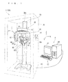
- FIG. 1 is a schematic perspective view of an X-ray CT photographic apparatus 1 according to a preferred embodiment.
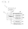
- FIG. 2 is a block diagram illustrating a schematic configuration of the X-ray CT photographic apparatus 1 illustrated in FIG. 1 .
- FIG. 3 is a view illustrating a functional block included in an image processing device 80 illustrated in FIG. 1 together with a data flow.
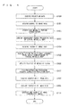
- FIG. 4 is a flowchart of metallic artifact removal.
- the X-ray CT photographic apparatus 1 illustrated in FIG. 1 is roughly divided into a manipulation display unit 61, a main body 2, and an information processing device 8.
- the manipulation display unit 61 sets a CT photographic region to an interest region, and also has a function of display means, and the manipulation display unit 61 is manipulation means that receives a manipulation of an operator.
- the main body 2 performs X-ray CT photography to the CT photographic region set by the manipulation display unit 61, and collects projection data.
- the information processing device 8 processes the projection data collected by the main body 2, and generates various images.
- the main body 2 is accommodated in a hollow, vertically long, rectangular-solid-shaped X-ray protection chamber 70.
- a main body controller 60 of the main body 2, a controller of the information processing device 8, and a calculator 801 perform the X-ray photography according to a program of the X-ray photography including the X-ray CT photography.
- the main body 2, the manipulation display unit 61 mounted on a wall surface of the X-ray protection chamber 70, and the information processing device 8 disposed outside the X-ray protection chamber 70 are connected to one another using a connection cable 83.
- the main body 2 includes an X-ray generation unit 10 and an X-ray detection unit 20.
- the X-ray generation unit 10 includes an X-ray generator 10a that emits an X-ray beam toward a subject M1, and the X-ray beam includes an X-ray cone beam BX configured by a bundle of X-rays.
- the X-ray detection unit 20 includes an X-ray detector 21, which detects the X-ray beam transmitted through the subject M1 after the X-ray generation unit 10 emits the X-ray beam.
- the main body 2 also includes a turning arm 30 that is the support body supporting the X-ray generation unit 10 and X-ray detection unit 20, a support post 50 that extends vertically, a lifting unit 40 that can vertically be lifted with respect to the support post 50 while suspending the turning arm 30, and a main body controller 60.
- the X-ray generation unit 10, the X-ray detection unit 20, and a beam shaping mechanism disposed on a side of the X-ray detection unit 20 with respect to the X-ray generation unit 10 constitute a photographic mechanism.
- a MOS sensor, a CCD sensor, and a TFT can be cited as an example of the X-ray detector 21.
- a Flat Panel Detector (FPD) such as a CMOS sensor, an X-ray fluorescence intensifier tube (XII), the other solid-state imaging element and the like can be used as the X-ray detector 21.
- the X-ray generation unit 10 and the X-ray detection unit 20 are suspended from and fixed to both end portions of a turning unit 30c of the turning arm 30, respectively.
- the X-ray generation unit 10 and the X-ray detection unit 20 are supported so as to be opposed to each other.
- the turning arm 30 is suspended from and fixed to the lifting unit 40 with a vertically extending turning shaft interposed therebetween.
- the turning arm 30 has a substantially inverted U-shape when viewed from a front side, and the turning arm 30 turns about the turning shaft 31 provided in an upper end portion thereof.
- the turning center is fixed to an upper frame 41.
- the X-ray generation unit 10 and the X-ray detection unit 20 are attached to both the end portions of the turning arm 30, respectively.
- the turning arm 30 of the preferred embodiment is formed into the U-shape.
- the turning arm 30 may be formed into another shape.
- an annular member that is rotatably fitted in an outer circumferential portion of a columnar-shaped member with a ball bearing interposed therebetween may be used as the turning arm.
- the X-ray generation unit 10 and the X-ray detection unit 20 are attached to the annular member so as to be opposed to each other.
- a direction in the preferred embodiment, a vertical direction namely, a longitudinal direction
- a direction intersecting the Z-axis direction is referred to as an "X-axis direction”
- a direction intersecting the X-axis direction and Z-axis direction is referred to as a "Y-axis direction”.
- the X-axis direction and the Y-axis direction may arbitrarily be defined.
- a side-to-side direction of the test person is defines as the X-axis direction
- a front-back direction of the test person is defined as the Y-axis direction.
- the X-axis direction, the Y-axis direction, and the Z-axis direction are orthogonal to one another.
- the Z-axis direction is referred to as the vertical direction
- a direction on a plane defined by a two-dimensional direction of the X-axis direction and Y-axis direction is referred to as a horizontal direction.
- a direction in which the X-ray generation unit 10 and the X-ray detection unit 20 are opposed to each other is referred to as a "y-axis direction"
- a horizontal direction orthogonal to the y-axis direction is referred to as an "x-axis direction”
- a vertical direction orthogonal to the x-axis direction and y-axis direction is referred to as a "z-axis direction”.
- the z-axis direction and the Z-axis direction are parallel to each other.
- the direction from the X-ray generation unit 10 toward the X-ray detection unit 20 is referred to as a (+y) direction
- a horizontal right-hand direction in FIG. 1 , a front side of the subject M1 in an orientation of the turning arm 30
- a (+x) direction a horizontal right-hand direction orthogonal to the (+y) direction
- a (+z) direction an upward direction of the vertical direction
- the lifting unit 40 includes the upper frame 41 (the support body retention unit) and a lower frame 42, and engages with the support post 50 that is vertically provided along the vertical direction.
- the turning shaft 31 is attached to the functioning upper frame 41.
- the lifting unit 40 moves in the vertical direction along the support post 50, whereby the turning arm 30 moves up and down.
- the turning unit 30c of the turning arm 30 may be turnably provided to the turning shaft 31 which is unturnably fixed to the upper frame 41, and the turning arm 30 may turn with respect to the turning shaft 31.
- the turning unit 30c of the turning arm 30 may be unturnably fixed to the turning shaft 31 which is turnably provided to the upper frame 41, and the turning arm 30 may turn by turning the turning shaft 31.
- the former is used in the example illustrated in FIG. 1 .
- a turning motor (support body turning drive unit) is fixed to an inside of the turning arm 30, and a torque of the turning motor acts on the rotation of the turning arm 30, to which the turning motor is fixed, using a transmission mechanism (not illustrated) such as a belt and a pulley.
- a turning motor that turns the turning arm 30 about the turning shaft 31 may be provided in the upper frame 41, and the transmission mechanism (not illustrated), which includes a belt, a pulley, and a rotating shaft may transmit the torque of the turning motor (not illustrated) to the turning arm 30 to turn the turning arm 30 through the turning shaft 31.
- the structure may be employed such that the turning unit 30c of the turning arm 30 may be unturnably fixed to the turning shaft 31 which is turnably provided to the upper frame 41, and the turning arm 30 may turn by turning the turning shaft 31.
- the turning motor is fixed to the inside of the upper frame 41, the torque of the turning motor acts on the rotation of the turning shaft 31 using the transmission mechanism (not illustrated) such as a roller.
- the turning shaft 31 is configured to extend along the vertical direction.
- the turning shaft 31 may obliquely be disposed with an arbitrary angle with respect to the vertical direction.
- a bearing (not illustrated) is interposed between the turning shaft 31 and the turning arm 30. Therefore, the turning arm 30 can rotate smoothly with respect to the turning shaft 31.
- the turning shaft 31, the transmission mechanism including the bearing, the belt, the pulley, and the rotating shaft, and the turning motor are an example of the turning mechanism that turns the turning arm 30.
- the turning arm 30 turns with respect to the turning shaft 31 that is fixed to a fixed position so as not to rotate.
- the turning arm 30 may be turned by rotating the turning shaft 31 fixed to the turning arm 30 with respect to the upper frame 41.
- the bearing that rotatably supports the turning shaft 31 is formed on the side of the upper frame 41.
- a subject retention unit 421 including an ear rod for fixing the subject M1 (in the preferred embodiment, a head of a human body) from both left and right sides and a chin rest for fixing a chin is provided in the lower frame 42.
- the turning arm 30 is disposed in a proper position by lifting and lowering the lifting unit 40 according to a height of the subject M1.
- the subject M1 is fixed to the subject retention unit 421.
- the subject retention unit 421 retains the subject M1 such that a body axis of the subject M1 becomes the substantially same direction as the axis direction of the turning shaft 31.
- the main body controller 60 is a controller that controls an operation of each configuration of the main body 2.
- the main body controller 60 acts as an X-ray regulating controller and a drive controller.
- the main body controller 60 is disposed inside the X-ray detection unit 20.
- a manipulation display unit 62 is attached to a surface outside the main body controller 60, namely, on the side in the +Y direction of the X-ray detection unit 20.
- the manipulation display unit 62 is configured by buttons that are used to input various instructions and a touch panel that displays various pieces of information.
- the manipulation display unit 61 is attached to a surface outside the X-ray protection chamber 70 that accommodates the main body 2 therein.
- the manipulation display unit 61 is connected to the main body controller 60, and configured by buttons and the like that are used to input various instructions and a touch panel that displays various pieces of information.
- the operator may manipulate the main body 2 using the manipulation display unit 62, or manipulate the main body 2 using the manipulation display unit 61.
- the manipulation display unit 62 may differ from the manipulation display unit 61 in a manipulation content or a display content, or part or whole of the manipulation content or display content may be common to the manipulation display unit 62 and the manipulation display unit 61.
- the manipulation display unit 61 may be eliminated.
- One of the manipulation display unit 62 and the manipulation display unit 61 may be eliminated.
- the display and manipulation performed by the manipulation display unit 61 are described below. However, the display and manipulation performed by the manipulation display unit 61 may be replaced with the display and manipulation performed by the manipulation display unit 62.
- the manipulation display unit 61 is also used, for example, to assign a position and the like of a photographic region of a biological organ and the like. There are various modes in the X-ray photography, and the mode can be selected by the manipulation of the manipulation display unit 61.
- a CPU included in the image processing device 80 operates according to a predetermined program, whereby the calculator 801 acts as a normal CT image data acquisition unit 11P, a pseudo projection data acquisition unit 21P, a pseudo CT image data generator 22P, a virtual metallic body luminance acquisition unit 31P, a position specification unit 41P, a correction processor 51P, a correction CT image data acquisition unit 52P, and a synthesis processor 61P.
- a signal detected by each detection element of the X-ray detector 21 indicates intensity of the X-ray transmitted through the subject.
- the signal indicating the intensity of the transmission X-ray indicates the intensity of the X-ray transmitted through the subject.
- the signal indicating the intensity of the transmission X-ray is converted into a signal indicating an X-ray absorptance (or absorbance), whereby normal projection data 11D in FIG. 3 is generated and stored in a storage unit 802 (Step S100 in FIG. 4 ).
- the normal CT image data acquisition unit 11P reconstructs (back projection) the normal projection data 11D to acquire normal CT image data 12D (Step S101 in FIG. 4 ).
- reconstruction calculation processing There is no particular limitation to reconstruction calculation processing.
- an FBP (Filtered Back Projection) method may be adopted.
- the generated normal CT image data 12D is three-dimensional volume data corresponding to a CT photographic region, and is configured by a voxel having a voxel value (luminance) corresponding to an X-ray absorption degree.
- the pseudo projection data acquisition unit 21P arranges a virtual metallic body having a predetermined X-ray absorption coefficient in the photographic region of the X-ray CT photography in a pseudo manner. At this point, desirably the virtual metallic body is arranged in the non-metallic region. Therefore, the pseudo projection data acquisition unit 21P binarizes the normal CT image data 12D using a predetermined threshold (Step S102 in FIG. 4 ).
- the threshold may previously be stored as an initial value in the storage unit 802 and the like, or automatically acquired by analyzing a histogram of the voxel value. Alternatively, the operator (practitioner) may assign the threshold.
- the metallic region and the non-metallic region are distinguished from each other by performing the binarization using the predetermined threshold.
- the metallic region a metallic body
- the threshold is not necessarily a value used to strictly distinguish the metallic region from the non-metallic region, but a value used to roughly distinguish the metallic region from the non-metallic region.
- the configuration in which the metallic region is avoided to determine the place where the virtual metallic body is arranged through the processing in Step S102 may be eliminated, instead the place where the virtual metallic body is arranged may be determined based on positional information on the subject M1, which is retained in the subject retention unit 421. That is, sometimes the position of the metallic body of the subject M1 becomes roughly clear when the position of the subject M1 is determined. For example, in a dental clinic, because almost the metallic body is arranged in a position on a dental arch, the rough position of the metallic body can relatively easily specified from the position of the subject M1. For example, even if the metallic body exists, the place where the metallic body exists can be determined on the dental arch.
- the virtual metallic body may be arranged in positions of virtual metallic bodies 91VM and 93VM illustrated in FIG. 7 .
- the position where the virtual metallic body is arranged may be determined based on the positional information on the subject M1 and the positional information on the metallic body, which is obtained by the binarization processing.
- the pseudo projection data acquisition unit 21P arranges the virtual metallic body in the non-metallic region in the pseudo manner, and acquires pseudo projection data 21D by calculation (Step S103 in FIG. 4 ).
- exp(x) represents the x-th power of e (the base of natural logarithm, Napier number)
- I 0 represents original X-ray intensity (that is, an X-ray transmittance when the virtual metallic body is not arranged)
- T represents a distance of the virtual metallic body transmitting the X-ray.
- ⁇ is an X-ray attenuation coefficient of the virtual metallic body.
- a voxel size is set to 0.3 cubic millimeter, and the virtual metallic body is made of gold.
- the X-ray absorption coefficient (attenuation coefficient) ⁇ is 0.97.
- the X-ray absorption coefficient ⁇ is 0.94 in the case that the virtual metallic body is made of titanium.
- the X-ray absorption coefficient ⁇ is properly set according to the state of the metal existing currently in the CT photographic region of the subject M1 or an environment in which the X-ray CT photography is performed.
- the pseudo projection data acquisition unit 21P calculates a pixel value indicating the new X-ray absorption degree in each pixel of the projection image expressed by the normal projection data 11D in the case that the virtual metallic body is arranged in the pseudo manner. Therefore, the pseudo projection data 21D is acquired.
- the pseudo CT image data generator 22P reconstructs the pseudo projection data 21D to generate and acquire pseudo CT image data 22D (Step S104 in FIG. 4 ). This calculation processing is similar to the calculation processing performed by the normal CT image data acquisition unit 11P in Step S102.
- the virtual metallic body luminance acquisition unit 31P acquires luminance (virtual metallic body luminance 31D) corresponding to the virtual metallic body in the pseudo CT image data 22D (Step S105 in FIG. 4 ).
- the virtual metallic body luminance 31D may include not one voxel value but plural voxel values.
- the voxel values existing in a given range may be used as the virtual metallic body luminance 31D.
- the position specification unit 41P specifies a metal equivalent region having the luminance corresponding to the virtual metallic body luminance 31D, for example, the position in the region where the absorption coefficient becomes identical to that of the virtual metallic body as the position (a metallic body position) in which the metallic body similar to the virtual metallic body exists (Step S106 in FIG. 4 ). Therefore, the position (the metallic body position) of the metallic body having the X-ray absorption coefficient similar to that of the virtual metallic body is specified.
- the position specification unit 41P retains the specified metallic body position as position specification data 41D in the storage unit 802.
- the position specification unit 41P may assign a range where the position of the metallic body equivalent region is specified. For example, in the case that the rough position of the metallic body is already known, a time necessary for the calculation processing can be shortened by restricting the range.
- the correction processor 51P generates and acquires correction projection data 51D by performing correction processing of correcting degradation of the X-ray intensity due to X-ray absorption to the metallic body position specified by the position specification unit 41P in the normal projection data 11D (Step S107 in FIG. 4 ). Specifically, the correction processor 51P performs the correction processing to the luminance in the metallic body position in the projection image of the normal projection data 11D based on the luminance of each of the pixels on both sides in a predetermined direction. Preferably, linear interpolation in which the calculation is easily performed is adopted as a correction processing method. Alternatively, other interpolation processing techniques such as polynomial interpolation and wavelet interpolation or similar interpolation processing techniques may be adopted.
- the correction CT image data acquisition unit 52P reconstructs the correction projection data 51D to generate and acquire correction CT image data 52D (Step S108 in FIG. 4 ). Therefore, the CT image data (volume data) in which the metallic body portion is corrected by the proper luminance is generated.
- the correction projection data 51D used at this time is data in which the metallic body is removed through the correction processing, and the removed metallic body is filled with a tissue having the same X-ray transmittance as the adjacent tissue, thereby hardly generating the artifact (however, for the metal having the relatively low X-ray absorption factor, sometimes special processing is performed like titanium as described later). Accordingly, the correction CT image data 52D is data in which a metallic artifact derived from the metallic body is reduced.
- the range where the correction projection data 51D is reconstructed may be restricted to a surrounding area of the metallic body, and the normal CT image data 12D may directly be used for the remaining portion of the CT photographic region. Therefore, a calculation processing time necessary to acquire the correction CT image data 52D can be shortened.
- the synthesis processor 61P synthesizes the normal CT image data 12D and the correction CT image data 52D to generate and acquire synthesis CT image data 61D (Step S109 in FIG. 4 ). Particularly, the corrected luminance of the metal equivalent region in the correction CT image data 52D is converted into the luminance (that is, the original luminance equivalent to the metallic body) in the same position in the normal CT image data 12D. The position of the metal equivalent region is specified by the position specification unit 41P, so that the correct conversion can be performed. Therefore, the information on the luminance of the metallic body is buried in the correction CT image data 52D.
- the image processing device 80 When the operator assigns a tomographic position through a manipulation unit 82, the image processing device 80 generates a tomographic image in the assigned position using the synthesis CT image data 61D, and displays the tomographic image on a display unit 81 (Step S110 in FIG. 4 ).
- the synthesis CT image data 61D is three-dimensional volume data, in which the luminance information on the metallic body is buried in the correction CT image data 52D in which the metallic body is removed to reduce the metallic artifact. Therefore, the CT image, in which the metallic body is photographed in the correct position while the metallic artifact is reduced, can be acquired using the synthesis image data 61D.
- FIG. 5 is a view illustrating an example of a normal projection image 90 expressed by the normal projection data 11D.
- plural gold materials 91M and plural titanium materials 93M which are used as a dental prosthesis, are included as the metallic body in the CT photographic region.
- the gold material 91M is used as an artificial tooth
- the titanium material 93M is used as an implant bolt used to attach the artificial tooth to a chin.
- the normal projection image 90 is expressed such that the luminance of the pixel becomes brighter with increasing X-ray absorption. Because the X-ray is absorbed in the gold material 91M and the titanium material 93M, the luminance becomes brighter in the gold material 91M and the titanium material 93M on the normal projection image 90.
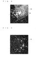
- FIG. 6 is a view illustrating an example of a normal CT image 91 expressed by the normal CT image data 12D.
- the normal CT image 91 illustrated in FIG. 6 is a tomographic image relating to the horizontal plane (an XY-plane) near a height of a lower jaw (specifically, a height of a line 90L illustrated in FIG. 5 ).
- the streak noise the metallic artifact
- the surround the region surrounded by a broken line of the metallic body (in the preferred embodiment, the gold material 91M).
- FIG. 7 is a view illustrating an example of a binarized CT image 92 expressed by binarization CT image data in which the normal CT image 91 is binarized.
- the pseudo projection data acquisition unit 21P binarizes the normal CT image data 12D in order to determine the position where the virtual metallic body is arranged in the pseudo manner (S102 in FIG. 4 ). Therefore, the metallic body portion (the gold material 91M) and the non-metallic body portion are separated from each other by the binarization of the normal CT image 91.
- the pseudo projection data acquisition unit 21P arranges the virtual metallic body (in the preferred embodiment, the virtual gold material 91VM and the virtual titanium material 93VM) in the pseudo manner in the region (the non-metallic region) except the metal extracted in this manner. In the example illustrated in FIG. 7 , the virtual metallic body is arranged so as to pierce a tongue portion inside the dental arch.
- Each of the virtual gold material 91VM and the virtual titanium material 93VM is configured by a cylinder solid member extending in parallel with the turning shaft 31 of the turning arm 30 that is the support body of the X-ray CT photographic apparatus 1.
- a length in the z-axis direction of each of the virtual gold material 91VM and the virtual titanium material 93VM is set to be equal to or longer than a length in the z-axis direction of the CT photographic region expressed by the normal CT image data 12D.
- FIG. 8 is a view illustrating an example of a pseudo projection image 93 expressed by the pseudo projection data 21D.
- the pseudo projection image 93 using the equation (1), the X-ray absorption degree is newly calculated in each pixel of the normal CT image 91 in the case that the virtual metallic body is arranged.
- the X-ray absorption coefficient ⁇ of the virtual gold material 91VM is set to 0.97
- the X-ray absorption coefficient ⁇ of the virtual titanium material 93VM is set to 0.94.
- the pseudo projection image 93 in which the virtual gold material 91 VM and the virtual titanium material 93VM are photographed in the pseudo manner is acquired by arranging the virtual gold material 91 VM and the virtual titanium material 93VM in the CT photographic region in the pseudo manner.
- the virtual gold material 91VM is seen because the virtual gold material 91VM is disposed on the front side.
- the virtual titanium material 93VM is also photographed in the pseudo projection image 93 when the pseudo projection image 93 is viewed from another angle.
- the virtual gold material 91VM and the virtual titanium material 93VM are formed into the cylinder solid shape. Therefore, the X-ray absorption degree of the virtual metallic body is substantially homogenized among plural pseudo projection images 93 expressed by the pseudo projection data 21D. Because the appropriate virtual metallic body luminance 31D can be acquired, the position of the metallic body corresponding to the virtual metallic body can successfully be specified. However, the shape or size of the virtual metallic body can arbitrarily be changed. Preferably the virtual metallic body is formed into the cylinder solid or the substantial cylinder solid.
- FIG. 9 is a view illustrating an example of a pseudo CT image 94 expressed by the pseudo CT image data 22D.
- the pseudo CT image data 22D including the virtual metallic body is acquired by reconstructing the pseudo projection data 21D. Therefore, the luminance of each of the virtual gold material 91VM and the virtual titanium material 93VM is acquired on the pseudo CT image data 22 (Step S105 in FIG. 4 ). The luminance is acquired as the virtual metallic body luminance 31D. Note that in FIG. 9 , only the virtual gold material 91VM and the virtual titanium material 93VM are highlighted in order to emphasize the positions of the virtual gold material 91 VM and virtual titanium material 93VM.
- the virtual metallic body luminance 31D is not the luminance of one value but the luminance that is wide to some extent. For this reason, the luminance corresponding to each of the virtual gold material 91VM and the virtual titanium material 93VM is set to the luminance having a required range. At this point, the luminance equivalent to the X-ray absorption coefficient ⁇ of 0.97 or more is set to the luminance corresponding to the virtual gold material 91 VM, and the luminance equivalent to the X-ray absorption coefficient ⁇ that is greater than or equal to 0.94 and less than 0.97 is set to the luminance corresponding to the virtual titanium material 93VM.
- the position specification unit 41P specifies the region having the luminance corresponding to the virtual metallic body luminance 31D as the metal equivalent region. Specifically, the gold equivalent region is specified as the metal equivalent region for the virtual gold material 91VM, and the titanium equivalent region is specified as the metal equivalent region for the virtual titanium material 93VM.
- the CT image of the virtual metallic body portion and the CT image of the metallic body portion can be reconstructed under the same reconstruction condition by acquiring the pseudo projection data 21D. For example, even if the condition varies such that the subjects have different bone densities, the accuracy of the specification of the metal equivalent region can be enhanced.
- FIG. 10 is a view illustrating an example of a region separation CT image 95 that is separated into a gold equivalent region (white), a titanium equivalent region (gray), and a non-metal equivalent region (black).
- the gold equivalent region means the region having the luminance (at this point, the X-ray absorption coefficient ⁇ of 0.97 or more) corresponding to the luminance of the virtual gold material 91 VM in the normal CT image data 12D
- the titanium equivalent region means the region having the luminance (the X-ray absorption coefficient ⁇ is greater than or equal to 0.94 and less than 0.97) corresponding to the luminance of the virtual titanium material 93VM in the normal CT image data 12D
- the non-metal equivalent region means the region (the region where X-ray absorption coefficient ⁇ is less than 0.94) that does not correspond to the gold equivalent region and the titanium equivalent region in the normal CT image data 12D.
- the CT image data (region separation CT image data) expressing the region separation CT image 95 is generated by quantifying the normal CT image data 12D to three levels with the virtual metallic body luminance 31D relating to the virtual gold material 91VM and virtual titanium material 93VM as the threshold.
- the region separation CT image 95 may be generated by binarizing the normal CT image data 12D.
- the region where the X-ray absorption coefficient ⁇ is greater than 0.94 may be set to the metal equivalent region.
- the position of metal equivalent region can be specified by applying the virtual metallic body luminance 31D to the normal CT image data 12D, besides, can be specified by applying the virtual metallic body luminance 31D to the pseudo CT image data 22D. In this case, calculation adjustment for example by subtruction and the like that is done for obstructing the position of the virtual metallic body itself should be regarded as the position of the metal equivalent region.
- the position specification unit 41P When acquiring the region separation CT image data expressing the region separation CT image 95, the position specification unit 41P performs the calculation processing of projecting the region separation CT image data onto the two-dimensional plane. As a result, the gold equivalent region, the titanium equivalent region, and the non-metal equivalent region can be distinguished from one another on the projection image expressed by the two-dimensional plane. Thus, the position specification unit 41P specifies the positions of gold and titanium that are the metallic body, and acquires the positional information as the position specification data 41D.
- FIG. 11 is a view illustrating an example of a metal extraction projection image 96 with respect to the metal equivalent region.
- the metal extraction projection image 96 illustrated in FIG. 11 is the projection image that is obtained on the assumption that, in the normal CT image data 12D, the metal equivalent region indicated by the region separation CT image data is irradiated with the X-ray from the same direction (in this case, the left side of the subject M1) as the X-ray CT photography, and the metal extraction projection image 96 is the image acquired through the predetermined calculation processing.
- the region (a background) except the metal equivalent region is illustrated in gray for the sake of convenience.
- the luminance is saturated because the X-ray is substantially absorbed.
- the portion having the high luminance and the portion having the low luminance exist because the X-ray is partially transmitted.
- the metal extraction projection image 96 is used in the following correction processing.
- FIG. 12 is a view illustrating an example of a correction projection image 97 expressed by correction projection data 51D.
- the correction projection image 97 is acquired such that the correction processor 51P refers to the position specification data 41D to perform the correction processing to the metallic body portion included in the normal projection data 11D.
- the different pieces of correction processing are performed to the gold equivalent region and the titanium equivalent region, respectively. The correction processing will be described below.
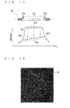
- FIG. 13 is a view illustrating interpolation processing performed to the gold equivalent region by the correction processor 51P.
- plural successive pixels 91p specified as the gold equivalent region in the inside portion of plural pixels arrayed in the horizontal direction (the x-axis direction) and pixels (such as pixels 92p and 93p) located on both sides of the plural pixels 91p are illustrated in the normal projection image 90 (for example, see FIG. 5 ) expressed by the normal projection data 11D.
- the luminance of each pixel group is plotted on a two-dimensional graph illustrated in a lower stage of FIG. 13 . As can be seen from a line graph connecting the plotted points, because the pixel 91p constituting the gold equivalent region has the X-ray absorption degree larger than that of the surround, the pixel 91p has luminance 91B higher than that of the surround.
- the correction processor 51P performs the interpolation processing to the sequence of pixels 91p
- the correction processor 51P extracts the surrounding area of the sequence of pixels 91p equivalent to the gold equivalent region in the x-axis direction, for example, the pixels 92p and 93p adjacent to the sequence of pixels 91p.
- the correction processor 51P determines new luminance 94B in each successive pixels 91p by performing the interpolation using pieces of luminance 92B and 93B of the pixels 92p and 93p.
- the luminance 92B of the pixel 92p and the luminance 93B of the pixel 93p are connected by a line segment 91L indicated by a broken line as illustrated in FIG. 13 .
- the luminance in the corresponding position on the line segment 91L is used as the new luminance 94B of the pixel 91p in each sequence of pixels 91p.
- the interpolation processing is performed in the horizontal direction of the normal projection image 90.
- the interpolation processing may be performed in the perpendicular direction of the normal projection image 90. That is, the interpolation processing may be performed using the luminance of the pixel adjacent to the metal equivalent region in the perpendicular direction.
- the pixels on the left and right sides in the horizontal direction or the pixels on the top and bottom sides in the perpendicular direction may be used as the surrounding pixels used in the interpolation.
- the pixels on the left, right, top, and bottom sides may be used.
- the gold equivalent region specified by the position specification unit 41P may be enlarged (thickened) in the horizontal direction or perpendicular direction of the image by at least one adjacent pixel or more, specifically one pixel or two pixels.
- the correction processor 51P may perform the interpolation processing with the enlarged region as the new gold equivalent region. In the interpolation processing, the use of the luminance of the pixel (for example, the pixels 92p and 93p) that possibly includes the noise can be restricted.
- the interpolation processing of the luminance is performed using the luminance of the pixel equivalent to the boundary portion of the region outside the gold equivalent region, whereby the gold equivalent region is removed from the original normal projection image 90.
- the correction processing of removing the X-ray absorption degree of the titanium material 93 from the titanium equivalent region in the original normal projection image 90 is performed in the titanium equivalent region.
- the calculation processing of subtracting the luminance that is, the luminance of the pixel in the corresponding position on the metal extraction projection image 96
- the projection image in which the X-ray absorption degree equivalent to the titanium material 93M is removed can be acquired from the normal projection image 90.
- the transmission of the X-ray is relatively generated compared with the metal, such as gold, which has the high X-ray absorption factor.
- the X-ray absorption degree indicated by the pixel in the position where the X-ray is transmitted through the titanium material 93M on the normal projection image 90 includes information (the tooth and living tissues such as a muscular tissue) except the titanium portion transmitting the X-ray. Accordingly, in the titanium equivalent region, the information on the X-ray absorption degree except titanium is left by subtracting the luminance, and the information on the CT photographic region of the subject M1 can be retained while lost through the correction processing as little as possible. Like the gold equivalent region, the correction processing such as the linear interpolation described in FIG. 13 may be applied to the titanium equivalent region.
- the correction processing may not be performed.
- the rapid attenuation is generated in the case that the transmission distance of the X-ray through the titanium material 93M is lengthened such that the plural titanium materials 93M exist on a traveling path of the X-ray. Therefore, when the projection data is reconstructed, possibly the metallic artifact is generated due to the titanium material 93M.
- the correction processing is performed to the metallic material such as the titanium equivalent region having the relatively low X-ray absorption factor such that X-ray absorption degree derived from the metal is removed from the normal projection data 11D
- FIG. 14 is a view illustrating an example of a correction CT image 98 expressed by the correction CT image data 52D.
- the correction CT image 98 in which the gold material 91M and titanium material 93M photographed in the normal CT image 91 (see FIG. 6 ) are partially or wholly removed is generated through the correction processing.
- the metallic artifact which is generated in the surrounding area of the metallic body and surrounded by a broken line of FIG. 14 is reduced by removing the metallic body.
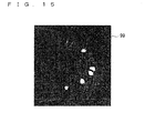
- FIG. 15 is a view illustrating an example of a synthesis CT image 99 expressed by the synthesis CT image data 61D.
- the synthesis CT image data 61D is the volume data that is obtained by converting the luminance (the voxel value) of the metal equivalent region (the gold equivalent region and the titanium equivalent region) in the correction CT image data 52D into the luminance in the same position in the normal CT image data 12D.
- the information on the metallic body is added to the synthesis CT image data 61D in which the metallic body is removed. Therefore, like the synthesis CT image 99 illustrated in FIG. 15 , the image of the metallic body is synthesized on the correction CT image 98 in which the metallic body is removed.
- the CT image expressing the original CT photographic region in which the metallic artifact is reduced can be generated.
- the correction processor 51P may perform low-pass filter processing in order to enhance the accuracy of the image reconstruction.
- the X-ray image is detected by the X-ray detector 21 including a detection surface configured by many pixels
- a boundary between the metallic region and the non-metallic region is used as an edge
- an image signal of the projection image in an edge portion becomes a high-frequency component when the image of the edge is clear.
- the edge portion has an influence on the reconstruction image by an aliasing effect. Therefore, the influence may be reduced by applying a low-pass filter only to the edge portion.
- the position specification unit 41P can specify the metallic body position with high accuracy. Therefore, the position corresponding to the boundary between the metal equivalent region and the region except the metal equivalent region in the normal projection data received by the detection surface of the X-ray detector 21, namely, the position of the edge can also be specified with high accuracy. With this, the low-pass filter is applied only to the position of the detected edge to suppress the aliasing, and the accuracy of the image reconstruction can be improved.
- the X-ray CT photographic apparatus 1 may perform the local X-ray CT photography.
- the local X-ray CT photography means photography in which only a partial region in the subject M1, namely, a local portion is irradiated with the X-ray to detect the transmitted X-ray and the CT image is reconstructed, or photography in which the region including the local portion is irradiated with the X-ray to detect only the X-ray transmitted through the local portion and the CT image is reconstructed.
- a diagnosis whether a wisdom tooth is in an overturned state in a buries wisdom tooth region a diagnosis whether various tumors are widened, or a diagnosis of part of the dental arch or a surrounding portion (a tongue side portion or a cheek portion) of the dental arch is made in the dental clinic.
- a local CT photographic region is set with a couple of teeth as a local photographic object.
- scattering line generation amount is decreased compared with the photography of the large region, and the small-noise CT image can be reconstructed.
- the pseudo manner can be converted or referred to simulation manner;
- the pseudo projection data can be converted or referred to simulated projection data;
- the pseudo projection data acquisition unit can be converted or referred to simulated projection data acquisition unit;
- the pseudo projection image can be converted to or referred simulated projection image;
- the pseudo CT image data can be converted or referred to simulated CT image data;
- the pseudo CT image data generator can be converted or referred to simulated CT image data generator;
- the virtual metallic body can be converted or referred to simulated metallic body;
- the virtual titanium material can be converted or referred to simulated titanium material;
- the virtual gold material can be converted or referred to simulated gold material;
- the virtual metallic body luminance can be converted or referred to simulated metallic body luminance.
- the term "simulated” may be referred to as "imitative” and the term “simulation” may be referred to as "imitation".
- the virtual gold material 91 VM and the virtual titanium material 93VM are arranged in the pseudo manner as the virtual metallic body.
- another virtual metal may be arranged. Only one kind of virtual metallic body or at least three kinds of virtual metallic bodies may be arranged.
Landscapes
- Engineering & Computer Science (AREA)
- Health & Medical Sciences (AREA)
- Life Sciences & Earth Sciences (AREA)
- Medical Informatics (AREA)
- Physics & Mathematics (AREA)
- General Physics & Mathematics (AREA)
- Theoretical Computer Science (AREA)
- General Health & Medical Sciences (AREA)
- Nuclear Medicine, Radiotherapy & Molecular Imaging (AREA)
- Radiology & Medical Imaging (AREA)
- Computer Vision & Pattern Recognition (AREA)
- Biophysics (AREA)
- High Energy & Nuclear Physics (AREA)
- Optics & Photonics (AREA)
- Pathology (AREA)
- Biomedical Technology (AREA)
- Heart & Thoracic Surgery (AREA)
- Molecular Biology (AREA)
- Surgery (AREA)
- Animal Behavior & Ethology (AREA)
- Public Health (AREA)
- Veterinary Medicine (AREA)
- Quality & Reliability (AREA)
- Apparatus For Radiation Diagnosis (AREA)
Abstract
Description
- The present invention relates to a technology of reducing a metallic artifact by extracting a position of a metallic body included in a CT photographic region in X-ray CT photography.
- Conventionally, the X-ray CT photography is performed in a medical field and the like. In the X-ray CT photography, a subject is irradiated with an X-ray to collect projection data expressing a projection image, and the projection data is reconstructed on a computer to generate a CT (Computed (Computerized) Tomography) image (tomographic image).
- In the X-ray CT photography, the subject is disposed between an X-ray generator and an X-ray detector, the X-ray generator and the X-ray detector turn about the subject, and the X-ray generator emits the conical X-ray (an X-ray cone beam) to subject. The X-ray detector collects a detection result (projection data) of the X-ray, and CT image data (volume data) is reconstructed based on the collected detection result of the X-ray.
- In the case that a metallic body having a high X-ray absorption factor is included in the CT photographic region, the X-ray is hardly transmitted through the metallic body, and a correct transmission amount is hardly measured. Therefore, sometimes many streak noises (metallic artifacts) are generated around the metallic body on the CT image (the tomographic image) that is obtained by reconstructing the projection data. In the case that the metallic artifact is generated, a correct image diagnosis is hardly performed. Therefore, some methods of removing the metallic artifact have been proposed (for example, see Japanese Patent Publication Laid-Open No.
2010-099114 - Specifically, in the technology disclosed in Japanese Patent Publication Laid-Open No.
2010-099114 - However, in the technology, it is necessary to properly set the threshold in order to separate a metallic portion from a non-metallic portion. Therefore, in the case that the threshold is improperly set, possibly the metallic artifact cannot properly be removed because the metal position is hardly specified with high accuracy.
- Therefore, an object of the present invention is to provide a technology of properly specifying the metallic body position in the CT photographic region.
- The objects underlying the present invention are achieved by image processing device according to
independent claim 1, by an X-ray CT photographic apparatus according to independent claim 13, and by an image processing method according to independent claim 14. Preferred embodiments are defined in the dependent claims. - The present invention is directed to an image processing device that acquires CT image data by reconstructing projection data, which is acquired by performing X-ray CT photography of a region including a metallic body in a subject.
- According to the present invention, the image processing device includes: a pseudo projection data acquisition unit that is configured to acquire pseudo projection data by calculation when a virtual metallic body having a predetermined X-ray absorption coefficient is arranged in a photographic region of the X-ray CT photography in a pseudo manner based on the projection data; a pseudo CT image data generator that is configured to reconstruct the pseudo projection data to generate pseudo CT image data; a virtual metallic body luminance acquisition unit that is configured to acquire virtual metallic body luminance that is luminance corresponding to the virtual metallic body in the pseudo CT image data; a position specification unit that is configured to specify a position of a metal equivalent region having luminance corresponding to the virtual metallic body luminance in CT image data, the projection data being reconstructed in the CT image data; a correction processor that is configured to acquire correction projection data by performing correction processing to the luminance of the metal equivalent region in the projection data, degradation of X-ray intensity due to X-ray absorption being corrected through the correction processing; and a correction CT image data acquisition unit that is configured to reconstruct the correction projection data to acquire correction CT image data.
- The luminance of the virtual metallic body arranged in the pseudo manner is acquired to specify the position of the luminance equivalent to the luminance of the virtual metallic body, whereby the position of the metallic body included in the photographic region can be specified with high accuracy. Accordingly, the metallic artifact, which is generated in the CT image acquired by the reconstruction, can successfully be reduced by performing the correction processing to the position of the metallic body.
- Preferably the correction processor is configured to perform the correction processing to the luminance of the metal equivalent region in the projection data according to luminance in a surrounding area of the metal equivalent region.
- The luminance of the metal equivalent region in which the position is specified is interpolated according to the luminance of the surrounding area. Therefore, the metal equivalent region can be corrected according to the luminance of the surrounding area. Accordingly, the metallic artifact, which is generated in the CT image (the tomographic image) acquired by the reconstruction, can be reduced.
- Preferably the image processing device further includes a synthesis processor that is configured to synthesize the correction CT image data and the CT image data by converting the luminance of the metal equivalent region in the correction CT image data according to luminance in an identical position in the CT image data.
- The corrected luminance of the metallic portion in the correction CT image data is converted into the luminance in the original CT image data. Therefore, the actual metallic body can be photographed on the CT image in which the metallic artifact is reduced.
- Preferably the projection data is acquired by local X-ray CT photography in which only a partial region in subject is irradiated with an X-ray.
- For the local CT photographic target region, the position of the metallic body in the CT image data can successfully be extracted.
- Preferably the projection data is acquired by an X-ray CT photographic apparatus, the X-ray CT photographic apparatus including: an X-ray generator that is configured to generate the X-ray; an X-ray detector that is configured to detect the X-ray transmitted through the subject; a support body that supports the X-ray generator and the X-ray detector while the X-ray generator and the X-ray detector are opposed to each other in relation to the subject; and a support body turning drive unit that is configured to turn the support body about a turning shaft to turn the X-ray generator and the X-ray detector about the subject, and the virtual metallic body is formed into a cylinder solid or a substantial cylinder solid, the cylinder solid or the substantial cylinder solid being arranged so as to extend in parallel with the turning shaft.
- The shape of the virtual metallic body arranged in the pseudo manner is formed into the substantial cylinder solid that extends in parallel with the turning shaft of the support body of the X-ray CT photographic apparatus. Therefore, the X-ray absorption degree of the virtual metallic body is substantially homogenized among plural pseudo projection images expressed by the pseudo projection data. Therefore, because the appropriate virtual metallic body luminance can be acquired, the position of the metallic body corresponding to the virtual metallic body can successfully be specified.
- Preferably the X-ray CT photographic apparatus further includes a subject retention unit that retains the subject, and the virtual metallic body is arranged in a pseudo manner in a position different from the metallic body, which is determined based on positional information on the subject, the positional information on the subject being retained in the subject retention unit.
- The position of the metallic body existing currently in the subject is specified based on the positional information on the subject, which is retained in the subject retention unit, so that the virtual metallic body can be arranged in the pseudo manner by selecting the position different from the position of the metallic body.
- Preferably the position specification unit is configured to distinguish a metal equivalent region that is equivalent to the virtual metallic body from a region that is not equivalent to the virtual metallic body by binarizing the CT image data with luminance corresponding to the luminance of the virtual metallic body as a threshold.
- The region that is equivalent to the metallic body and the region that is not equivalent to the metallic body can be distinguished from each other.
- Preferably the pseudo projection data acquisition unit is configured to acquire the pseudo projection data by calculation when the plural kinds of virtual metallic bodies having the X-ray absorption coefficients different from each other are arranged in a pseudo manner based on the projection data, and the position specification unit is configured to individually specify a position of a region having luminance corresponding to the virtual metallic body luminance of each of the plural kinds of virtual metallic bodies in the CT image data, in which the projection data is reconstructed, as the metal equivalent region.
- In the case that the plural kinds of metallic bodies are included in the photographic region of the subject, the position can be specified in each metallic body.
- Preferably the correction processor is configured to correct the luminance by subtracting an X-ray absorption degree of the metal equivalent region corresponding to the virtual metallic body from X-ray absorption degrees of the metal equivalent regions equivalent to some virtual metallic bodies having the low X-ray absorption coefficients in the plural kinds of virtual metallic bodies in the projection data.
- The correction projection data, in which the metallic bodies equivalent to some virtual metallic bodies having the high X-ray absorption coefficient are removed from the original projection data, can be generated through the correction processing. Therefore, the CT image can be generated while the information on the X-ray absorption degree in portion except the metallic body is left as much as possible.
- Preferably the position specification unit is configured to distinguish a metallic body region corresponding to the high X-ray absorption coefficient in the two kinds of the virtual metallic bodies, a metallic body region corresponding to the low X-ray absorption coefficient, and a region that does not correspond to the two kinds of virtual metallic bodies from one another by quantifying the CT image data to three levels with luminance corresponding to luminance of each of the two kinds of virtual metallic bodies as a threshold.
- The region corresponding to each of the two kinds of metallic bodies and the region except the metallic bodies can successfully be distinguished from each other.
- Preferably the correction processor is configured to set a region where a region of the metallic body position in the projection data is enlarged so as to include at least one adjacent pixel to a target region of the correction processing.
- The interpolation processing of the luminance of the metal equivalent region can be reduced based on the luminance including the noise generated in the surrounding area of the metallic body on the projection image.
- Preferably the correction processor is configured to perform low-pass filter processing to projection data in a boundary portion between the metal equivalent region and a region except the metal equivalent region in the projection data.
- Through the low-pass filter processing, the boundary portion between the metallic region and the non-metallic region can be prevented from becoming clear. Therefore, in calculating CT reconstruction, aliasing can be prevented to improve the accuracy of the image reconstruction.
- The present invention is also directed to an X-ray CT photographic apparatus that acquires the CT image data by reconstructing projection data, which is acquired by performing the X-ray CT photography of the region including the metallic body in the subject.
- According to the present invention, the X-ray CT photographic apparatus includes: a pseudo projection data acquisition unit that is configured to acquire pseudo projection data by calculation when a virtual metallic body having a predetermined X-ray absorption coefficient is arranged in a photographic region of the X-ray CT photography in a pseudo manner based on the projection data; a pseudo CT image data generator that is configured to reconstruct the pseudo projection data to generate pseudo CT image data; a virtual metallic body luminance acquisition unit that is configured to acquire virtual metallic body luminance that is luminance corresponding to the virtual metallic body in the pseudo CT image data; a position specification unit that is configured to specify a position of a metal equivalent region having luminance corresponding to the virtual metallic body luminance in CT image data, the projection data being reconstructed in the CT image data; a correction processor that is configured to acquire correction projection data by performing correction processing to the luminance of the metal equivalent region in the projection data, degradation of X-ray intensity due to X-ray absorption being corrected through the correction processing; and a correction CT image data acquisition unit that is configured to reconstruct the correction projection data to acquire correction CT image data.
- The present invention is also directed to an image processing method of acquiring the CT image data by reconstructing projection data, which is acquired by performing the X-ray CT photography of the region including the metallic body in the subject.
- According to the present invention, the image processing method includes the steps of: (a) acquiring pseudo projection data by calculation when a virtual metallic body having a predetermined X-ray absorption coefficient is arranged in a photographic region of the X-ray CT photography in a pseudo manner based on the projection data; (b) reconstructing the pseudo projection data to generate pseudo CT image data; (c) acquiring virtual metallic body luminance of the virtual metallic body in the pseudo CT image data; (d) specifying a position of a metal equivalent region having luminance corresponding to the virtual metallic body luminance in CT image data in which the projection data is reconstructed; (e) acquiring correction projection data by performing correction processing to the luminance of the metal equivalent region in the projection data, degradation of X-ray intensity due to X-ray absorption being corrected through the correction processing; and (f) reconstructing the correction projection data to acquire correction CT image data.
- These and other objects, features, aspects and advantages of the present invention will become more apparent from the following detailed description of the present invention when taken in conjunction with the accompanying drawings.
-
-
FIG. 1 is a schematic perspective view of an X-ray CT photographic apparatus according to a preferred embodiment; -
FIG. 2 is a block diagram illustrating a schematic configuration of the X-ray CT photographic apparatus illustrated inFIG. 1 ; -
FIG. 3 is a view illustrating a functional block included in an image processing device illustrated inFIG. 1 together with a data flow; -
FIG. 4 is a flowchart of metallic artifact removal; -
FIG. 5 is a view illustrating an example of a normal projection image expressed by normal projection data; -
FIG. 6 is a view illustrating an example of a normal CT image expressed by normal CT image data; -
FIG. 7 is a view illustrating an example a binarized CT image in which the normal CT image is binarized; -
FIG. 8 is a view illustrating an example of a pseudo projection image expressed by pseudo CT image data; -
FIG. 9 is a view illustrating an example of a pseudo CT image expressed by the pseudo CT image data; -
FIG. 10 is a view illustrating an example of a region separation CT image that is separated into a gold equivalent region (white), a titanium equivalent region (gray), and a non-metal equivalent region (black); -
FIG. 11 is a view illustrating an example of a metal extraction projection image with respect to a metal equivalent region; -
FIG. 12 is a view illustrating an example of a correction projection image expressed by correction projection data; -
FIG. 13 is a view illustrating interpolation processing performed to the gold equivalent region by a correction processor; -
FIG. 14 is a view illustrating an example of a correction CT image expressed by correction CT image data; and -
FIG. 15 is a view illustrating an example of a synthesis CT image expressed by synthesis CT image data. - Hereinafter, a preferred embodiment of the present invention will be described with reference to the accompanying drawings. In the following drawings, for the sake convenience, sometimes a size or the number of pieces of each unit is illustrated while magnified or simplified as needed basis.
- The X-ray CT
photographic apparatus 1 may be composed of only an X-ray photographic apparatusmain body 100, or may be comprised of X-rayphotographic apparatus 100 andinformation processing device 8. Theinformation processing device 8 works as an individual information processing device, which does not always require the X-ray photographic apparatusmain body 100. In this case, theinformation processing device 8 performs image processing as described in this specification as long as data of an X-ray image is inputted. -
FIG. 1 is a schematic perspective view of an X-ray CTphotographic apparatus 1 according to a preferred embodiment.FIG. 2 is a block diagram illustrating a schematic configuration of the X-ray CTphotographic apparatus 1 illustrated inFIG. 1 .FIG. 3 is a view illustrating a functional block included in animage processing device 80 illustrated inFIG. 1 together with a data flow. In addition,FIG. 4 is a flowchart of metallic artifact removal. - The X-ray CT
photographic apparatus 1 illustrated inFIG. 1 is roughly divided into amanipulation display unit 61, amain body 2, and aninformation processing device 8. Themanipulation display unit 61 sets a CT photographic region to an interest region, and also has a function of display means, and themanipulation display unit 61 is manipulation means that receives a manipulation of an operator. Themain body 2 performs X-ray CT photography to the CT photographic region set by themanipulation display unit 61, and collects projection data. Theinformation processing device 8 processes the projection data collected by themain body 2, and generates various images. In the field of X-ray photography, preferably themain body 2 is accommodated in a hollow, vertically long, rectangular-solid-shapedX-ray protection chamber 70. - A
main body controller 60 of themain body 2, a controller of theinformation processing device 8, and acalculator 801 perform the X-ray photography according to a program of the X-ray photography including the X-ray CT photography. - The
main body 2, themanipulation display unit 61 mounted on a wall surface of theX-ray protection chamber 70, and theinformation processing device 8 disposed outside theX-ray protection chamber 70 are connected to one another using aconnection cable 83. - The
main body 2 includes anX-ray generation unit 10 and an X-ray detection unit 20. TheX-ray generation unit 10 includes anX-ray generator 10a that emits an X-ray beam toward a subject M1, and the X-ray beam includes an X-ray cone beam BX configured by a bundle of X-rays. The X-ray detection unit 20 includes an X-ray detector 21, which detects the X-ray beam transmitted through the subject M1 after theX-ray generation unit 10 emits the X-ray beam. Themain body 2 also includes a turningarm 30 that is the support body supporting theX-ray generation unit 10 and X-ray detection unit 20, asupport post 50 that extends vertically, a lifting unit 40 that can vertically be lifted with respect to thesupport post 50 while suspending the turningarm 30, and amain body controller 60. TheX-ray generation unit 10, the X-ray detection unit 20, and a beam shaping mechanism disposed on a side of the X-ray detection unit 20 with respect to theX-ray generation unit 10 constitute a photographic mechanism. - A MOS sensor, a CCD sensor, and a TFT can be cited as an example of the X-ray detector 21. Additionally, for example, a Flat Panel Detector (FPD) such as a CMOS sensor, an X-ray fluorescence intensifier tube (XII), the other solid-state imaging element and the like can be used as the X-ray detector 21.
- The
X-ray generation unit 10 and the X-ray detection unit 20 are suspended from and fixed to both end portions of aturning unit 30c of the turningarm 30, respectively. TheX-ray generation unit 10 and the X-ray detection unit 20 are supported so as to be opposed to each other. The turningarm 30 is suspended from and fixed to the lifting unit 40 with a vertically extending turning shaft interposed therebetween. - The turning
arm 30 has a substantially inverted U-shape when viewed from a front side, and the turningarm 30 turns about the turningshaft 31 provided in an upper end portion thereof. In the preferred embodiment, the turning center is fixed to an upper frame 41. TheX-ray generation unit 10 and the X-ray detection unit 20 are attached to both the end portions of the turningarm 30, respectively. - The turning
arm 30 of the preferred embodiment is formed into the U-shape. Alternatively, the turningarm 30 may be formed into another shape. For example, an annular member that is rotatably fitted in an outer circumferential portion of a columnar-shaped member with a ball bearing interposed therebetween may be used as the turning arm. In this case, theX-ray generation unit 10 and the X-ray detection unit 20 are attached to the annular member so as to be opposed to each other. - Hereinafter, a direction (in the preferred embodiment, a vertical direction namely, a longitudinal direction) parallel to an axis direction of the turning
shaft 31 is referred to as a "Z-axis direction", a direction intersecting the Z-axis direction is referred to as an "X-axis direction", and a direction intersecting the X-axis direction and Z-axis direction is referred to as a "Y-axis direction". The X-axis direction and the Y-axis direction may arbitrarily be defined. However, in the preferred embodiment, when a test person who is of the subject M1 is positioned in the X-ray CTphotographic apparatus 1 to face thesupport post 50 in correct position, a side-to-side direction of the test person is defines as the X-axis direction, and a front-back direction of the test person is defined as the Y-axis direction. In the preferred embodiment, it is assumed that the X-axis direction, the Y-axis direction, and the Z-axis direction are orthogonal to one another. Hereinafter, sometimes the Z-axis direction is referred to as the vertical direction, and a direction on a plane defined by a two-dimensional direction of the X-axis direction and Y-axis direction is referred to as a horizontal direction. - On the other hand, as to a three-dimensional coordinate on the turning
arm 30, a direction in which theX-ray generation unit 10 and the X-ray detection unit 20 are opposed to each other is referred to as a "y-axis direction", a horizontal direction orthogonal to the y-axis direction is referred to as an "x-axis direction" and a vertical direction orthogonal to the x-axis direction and y-axis direction is referred to as a "z-axis direction". In the preferred embodiment and subsequent preferred embodiments, the z-axis direction and the Z-axis direction are parallel to each other. The turningarm 30 of the preferred embodiment turns with the turningshaft 31 extending in the vertical direction as a rotating axis. Accordingly, the xyz orthogonal coordinate system rotates about the Z-axis (= the z-axis) with respect to the XYZ orthogonal coordinate system. - When the
X-ray generation unit 10 and X-ray detection unit 20 illustrated inFIG. 1 are viewed from above in plan, the direction from theX-ray generation unit 10 toward the X-ray detection unit 20 is referred to as a (+y) direction, a horizontal right-hand direction (inFIG. 1 , a front side of the subject M1 in an orientation of the turning arm 30) orthogonal to the (+y) direction is referred to as a (+x) direction, and an upward direction of the vertical direction is referred to as a (+z) direction. - The lifting unit 40 includes the upper frame 41 (the support body retention unit) and a
lower frame 42, and engages with thesupport post 50 that is vertically provided along the vertical direction. The turningshaft 31 is attached to the functioning upper frame 41. The lifting unit 40 moves in the vertical direction along thesupport post 50, whereby the turningarm 30 moves up and down. - As to the structure that turns the turning
arm 30, theturning unit 30c of the turningarm 30 may be turnably provided to the turningshaft 31 which is unturnably fixed to the upper frame 41, and the turningarm 30 may turn with respect to the turningshaft 31. Alternatively, theturning unit 30c of the turningarm 30 may be unturnably fixed to the turningshaft 31 which is turnably provided to the upper frame 41, and the turningarm 30 may turn by turning the turningshaft 31. - The former is used in the example illustrated in
FIG. 1 . In this case, a turning motor (support body turning drive unit) is fixed to an inside of the turningarm 30, and a torque of the turning motor acts on the rotation of the turningarm 30, to which the turning motor is fixed, using a transmission mechanism (not illustrated) such as a belt and a pulley. - Alternatively, a turning motor (not illustrated) that turns the turning
arm 30 about the turningshaft 31 may be provided in the upper frame 41, and the transmission mechanism (not illustrated), which includes a belt, a pulley, and a rotating shaft may transmit the torque of the turning motor (not illustrated) to the turningarm 30 to turn theturning arm 30 through the turningshaft 31. - Obviously, like the latter, the structure may be employed such that the
turning unit 30c of the turningarm 30 may be unturnably fixed to the turningshaft 31 which is turnably provided to the upper frame 41, and the turningarm 30 may turn by turning the turningshaft 31. In this case, the turning motor is fixed to the inside of the upper frame 41, the torque of the turning motor acts on the rotation of the turningshaft 31 using the transmission mechanism (not illustrated) such as a roller. - In the preferred embodiment, the turning
shaft 31 is configured to extend along the vertical direction. Alternatively, the turningshaft 31 may obliquely be disposed with an arbitrary angle with respect to the vertical direction. - A bearing (not illustrated) is interposed between the turning
shaft 31 and the turningarm 30. Therefore, the turningarm 30 can rotate smoothly with respect to the turningshaft 31. Herein, the turningshaft 31, the transmission mechanism including the bearing, the belt, the pulley, and the rotating shaft, and the turning motor are an example of the turning mechanism that turns the turningarm 30. In the preferred embodiment, the turningarm 30 turns with respect to the turningshaft 31 that is fixed to a fixed position so as not to rotate. However, as described above, the turningarm 30 may be turned by rotating the turningshaft 31 fixed to the turningarm 30 with respect to the upper frame 41. In this case, the bearing that rotatably supports the turningshaft 31 is formed on the side of the upper frame 41. - A
subject retention unit 421 including an ear rod for fixing the subject M1 (in the preferred embodiment, a head of a human body) from both left and right sides and a chin rest for fixing a chin is provided in thelower frame 42. - The turning
arm 30 is disposed in a proper position by lifting and lowering the lifting unit 40 according to a height of the subject M1. At this point, the subject M1 is fixed to thesubject retention unit 421. Note that in the example illustrated inFIG. 1 , thesubject retention unit 421 retains the subject M1 such that a body axis of the subject M1 becomes the substantially same direction as the axis direction of the turningshaft 31. - The
main body controller 60 is a controller that controls an operation of each configuration of themain body 2. For example, themain body controller 60 acts as an X-ray regulating controller and a drive controller. As illustrated inFIG. 1 , themain body controller 60 is disposed inside the X-ray detection unit 20. - A
manipulation display unit 62 is attached to a surface outside themain body controller 60, namely, on the side in the +Y direction of the X-ray detection unit 20. Themanipulation display unit 62 is configured by buttons that are used to input various instructions and a touch panel that displays various pieces of information. - The
manipulation display unit 61 is attached to a surface outside theX-ray protection chamber 70 that accommodates themain body 2 therein. Themanipulation display unit 61 is connected to themain body controller 60, and configured by buttons and the like that are used to input various instructions and a touch panel that displays various pieces of information. - The operator (practitioner) may manipulate the
main body 2 using themanipulation display unit 62, or manipulate themain body 2 using themanipulation display unit 61. Themanipulation display unit 62 may differ from themanipulation display unit 61 in a manipulation content or a display content, or part or whole of the manipulation content or display content may be common to themanipulation display unit 62 and themanipulation display unit 61. - In the case that the
X-ray protection chamber 70 is eliminated, themanipulation display unit 61 may be eliminated. One of themanipulation display unit 62 and themanipulation display unit 61 may be eliminated. The display and manipulation performed by themanipulation display unit 61 are described below. However, the display and manipulation performed by themanipulation display unit 61 may be replaced with the display and manipulation performed by themanipulation display unit 62. - The
manipulation display unit 61 is also used, for example, to assign a position and the like of a photographic region of a biological organ and the like. There are various modes in the X-ray photography, and the mode can be selected by the manipulation of themanipulation display unit 61. - As illustrated in
FIG. 3 , a CPU included in theimage processing device 80 operates according to a predetermined program, whereby thecalculator 801 acts as a normal CT imagedata acquisition unit 11P, a pseudo projectiondata acquisition unit 21P, a pseudo CTimage data generator 22P, a virtual metallic bodyluminance acquisition unit 31P, aposition specification unit 41P, acorrection processor 51P, a correction CT imagedata acquisition unit 52P, and asynthesis processor 61P. - A signal detected by each detection element of the X-ray detector 21 indicates intensity of the X-ray transmitted through the subject. The signal indicating the intensity of the transmission X-ray indicates the intensity of the X-ray transmitted through the subject. The signal indicating the intensity of the transmission X-ray is converted into a signal indicating an X-ray absorptance (or absorbance), whereby
normal projection data 11D inFIG. 3 is generated and stored in a storage unit 802 (Step S100 inFIG. 4 ). - The normal CT image
data acquisition unit 11P reconstructs (back projection) thenormal projection data 11D to acquire normalCT image data 12D (Step S101 inFIG. 4 ). There is no particular limitation to reconstruction calculation processing. For example, an FBP (Filtered Back Projection) method may be adopted. The generated normalCT image data 12D is three-dimensional volume data corresponding to a CT photographic region, and is configured by a voxel having a voxel value (luminance) corresponding to an X-ray absorption degree. - The pseudo projection
data acquisition unit 21P arranges a virtual metallic body having a predetermined X-ray absorption coefficient in the photographic region of the X-ray CT photography in a pseudo manner. At this point, desirably the virtual metallic body is arranged in the non-metallic region. Therefore, the pseudo projectiondata acquisition unit 21P binarizes the normalCT image data 12D using a predetermined threshold (Step S102 inFIG. 4 ). The threshold may previously be stored as an initial value in thestorage unit 802 and the like, or automatically acquired by analyzing a histogram of the voxel value. Alternatively, the operator (practitioner) may assign the threshold. In each case, the metallic region and the non-metallic region are distinguished from each other by performing the binarization using the predetermined threshold. Note that in distinguishing the metallic region and the non-metallic region from each other, the metallic region (a metallic body) existing currently in the CT photographic region is avoided to determine a place where the virtual metallic body is arranged. Accordingly, the threshold is not necessarily a value used to strictly distinguish the metallic region from the non-metallic region, but a value used to roughly distinguish the metallic region from the non-metallic region. - The configuration in which the metallic region is avoided to determine the place where the virtual metallic body is arranged through the processing in Step S102 may be eliminated, instead the place where the virtual metallic body is arranged may be determined based on positional information on the subject M1, which is retained in the
subject retention unit 421. That is, sometimes the position of the metallic body of the subject M1 becomes roughly clear when the position of the subject M1 is determined. For example, in a dental clinic, because almost the metallic body is arranged in a position on a dental arch, the rough position of the metallic body can relatively easily specified from the position of the subject M1. For example, even if the metallic body exists, the place where the metallic body exists can be determined on the dental arch. The positional overlapping of the metallic body and the virtual metallic body is avoided unless the virtual metallic body is arranged in the place corresponding to the dental arch of the head of the human body having a general skeletal frame. For example, as described later, the virtual metallic body may be arranged in positions of virtual metallic bodies 91VM and 93VM illustrated inFIG. 7 . Obviously, the position where the virtual metallic body is arranged may be determined based on the positional information on the subject M1 and the positional information on the metallic body, which is obtained by the binarization processing. - The pseudo projection
data acquisition unit 21P arranges the virtual metallic body in the non-metallic region in the pseudo manner, and acquirespseudo projection data 21D by calculation (Step S103 inFIG. 4 ). Note that, the X-ray absorption degree indicated by each pixel on the projection data is determined by an X-ray absorption factor of the transmitted substance. That is, when an X-ray absorption coefficient µ of the virtual metallic body is well known, intensity I of the X-ray transmitted through the virtual metallic body is calculated based on the following equation.
- In the equation (1), exp(x) represents the x-th power of e (the base of natural logarithm, Napier number), I0 represents original X-ray intensity (that is, an X-ray transmittance when the virtual metallic body is not arranged), and T represents a distance of the virtual metallic body transmitting the X-ray. µ is an X-ray attenuation coefficient of the virtual metallic body.
- For example, a voxel size is set to 0.3 cubic millimeter, and the virtual metallic body is made of gold. In this case, the X-ray absorption coefficient (attenuation coefficient) µ is 0.97. The X-ray absorption coefficient µ is 0.94 in the case that the virtual metallic body is made of titanium. However, the X-ray absorption coefficient µ is properly set according to the state of the metal existing currently in the CT photographic region of the subject M1 or an environment in which the X-ray CT photography is performed.
- Based on the equation (1), the pseudo projection
data acquisition unit 21P calculates a pixel value indicating the new X-ray absorption degree in each pixel of the projection image expressed by thenormal projection data 11D in the case that the virtual metallic body is arranged in the pseudo manner. Therefore, thepseudo projection data 21D is acquired. - The pseudo CT
image data generator 22P reconstructs thepseudo projection data 21D to generate and acquire pseudoCT image data 22D (Step S104 inFIG. 4 ). This calculation processing is similar to the calculation processing performed by the normal CT imagedata acquisition unit 11P in Step S102. - The virtual metallic body
luminance acquisition unit 31P acquires luminance (virtualmetallic body luminance 31D) corresponding to the virtual metallic body in the pseudoCT image data 22D (Step S105 inFIG. 4 ). Note that the virtualmetallic body luminance 31D may include not one voxel value but plural voxel values. For example, the voxel values existing in a given range may be used as the virtualmetallic body luminance 31D. - The
position specification unit 41P specifies a metal equivalent region having the luminance corresponding to the virtualmetallic body luminance 31D, for example, the position in the region where the absorption coefficient becomes identical to that of the virtual metallic body as the position (a metallic body position) in which the metallic body similar to the virtual metallic body exists (Step S106 inFIG. 4 ). Therefore, the position (the metallic body position) of the metallic body having the X-ray absorption coefficient similar to that of the virtual metallic body is specified. Theposition specification unit 41P retains the specified metallic body position asposition specification data 41D in thestorage unit 802. Theposition specification unit 41P may assign a range where the position of the metallic body equivalent region is specified. For example, in the case that the rough position of the metallic body is already known, a time necessary for the calculation processing can be shortened by restricting the range. - The
correction processor 51P generates and acquirescorrection projection data 51D by performing correction processing of correcting degradation of the X-ray intensity due to X-ray absorption to the metallic body position specified by theposition specification unit 41P in thenormal projection data 11D (Step S107 inFIG. 4 ). Specifically, thecorrection processor 51P performs the correction processing to the luminance in the metallic body position in the projection image of thenormal projection data 11D based on the luminance of each of the pixels on both sides in a predetermined direction. Preferably, linear interpolation in which the calculation is easily performed is adopted as a correction processing method. Alternatively, other interpolation processing techniques such as polynomial interpolation and wavelet interpolation or similar interpolation processing techniques may be adopted. - The correction CT image
data acquisition unit 52P reconstructs thecorrection projection data 51D to generate and acquire correctionCT image data 52D (Step S108 inFIG. 4 ). Therefore, the CT image data (volume data) in which the metallic body portion is corrected by the proper luminance is generated. Thecorrection projection data 51D used at this time is data in which the metallic body is removed through the correction processing, and the removed metallic body is filled with a tissue having the same X-ray transmittance as the adjacent tissue, thereby hardly generating the artifact (however, for the metal having the relatively low X-ray absorption factor, sometimes special processing is performed like titanium as described later). Accordingly, the correctionCT image data 52D is data in which a metallic artifact derived from the metallic body is reduced. In the case that the rough position of the metallic body is already known, the range where thecorrection projection data 51D is reconstructed may be restricted to a surrounding area of the metallic body, and the normalCT image data 12D may directly be used for the remaining portion of the CT photographic region. Therefore, a calculation processing time necessary to acquire the correctionCT image data 52D can be shortened. - The
synthesis processor 61P synthesizes the normalCT image data 12D and the correctionCT image data 52D to generate and acquire synthesisCT image data 61D (Step S109 inFIG. 4 ). Particularly, the corrected luminance of the metal equivalent region in the correctionCT image data 52D is converted into the luminance (that is, the original luminance equivalent to the metallic body) in the same position in the normalCT image data 12D. The position of the metal equivalent region is specified by theposition specification unit 41P, so that the correct conversion can be performed. Therefore, the information on the luminance of the metallic body is buried in the correctionCT image data 52D. - When the operator assigns a tomographic position through a
manipulation unit 82, theimage processing device 80 generates a tomographic image in the assigned position using the synthesisCT image data 61D, and displays the tomographic image on a display unit 81 (Step S110 inFIG. 4 ). The synthesisCT image data 61D is three-dimensional volume data, in which the luminance information on the metallic body is buried in the correctionCT image data 52D in which the metallic body is removed to reduce the metallic artifact. Therefore, the CT image, in which the metallic body is photographed in the correct position while the metallic artifact is reduced, can be acquired using thesynthesis image data 61D. - The flow of the metallic artifact removing processing is described above. A specific application example of the metallic artifact removing processing will be described below.
-
FIG. 5 is a view illustrating an example of anormal projection image 90 expressed by thenormal projection data 11D. In the example illustrated inFIG. 5 ,plural gold materials 91M andplural titanium materials 93M, which are used as a dental prosthesis, are included as the metallic body in the CT photographic region. Specifically, thegold material 91M is used as an artificial tooth, and thetitanium material 93M is used as an implant bolt used to attach the artificial tooth to a chin. - The
normal projection image 90 is expressed such that the luminance of the pixel becomes brighter with increasing X-ray absorption. Because the X-ray is absorbed in thegold material 91M and thetitanium material 93M, the luminance becomes brighter in thegold material 91M and thetitanium material 93M on thenormal projection image 90. -
FIG. 6 is a view illustrating an example of anormal CT image 91 expressed by the normalCT image data 12D. Thenormal CT image 91 illustrated inFIG. 6 is a tomographic image relating to the horizontal plane (an XY-plane) near a height of a lower jaw (specifically, a height of aline 90L illustrated inFIG. 5 ). As illustrated inFIG. 6 , in the case that the normal reconstruction (for example, the FBP method) is performed, the streak noise (the metallic artifact) is generated in the surround (the region surrounded by a broken line) of the metallic body (in the preferred embodiment, thegold material 91M). -
FIG. 7 is a view illustrating an example of abinarized CT image 92 expressed by binarization CT image data in which thenormal CT image 91 is binarized. As described above, the pseudo projectiondata acquisition unit 21P binarizes the normalCT image data 12D in order to determine the position where the virtual metallic body is arranged in the pseudo manner (S102 inFIG. 4 ). Therefore, the metallic body portion (thegold material 91M) and the non-metallic body portion are separated from each other by the binarization of thenormal CT image 91. The pseudo projectiondata acquisition unit 21P arranges the virtual metallic body (in the preferred embodiment, the virtual gold material 91VM and the virtual titanium material 93VM) in the pseudo manner in the region (the non-metallic region) except the metal extracted in this manner. In the example illustrated inFIG. 7 , the virtual metallic body is arranged so as to pierce a tongue portion inside the dental arch. - Each of the virtual gold material 91VM and the virtual titanium material 93VM is configured by a cylinder solid member extending in parallel with the turning
shaft 31 of the turningarm 30 that is the support body of the X-ray CTphotographic apparatus 1. A length in the z-axis direction of each of the virtual gold material 91VM and the virtual titanium material 93VM is set to be equal to or longer than a length in the z-axis direction of the CT photographic region expressed by the normalCT image data 12D. -
FIG. 8 is a view illustrating an example of apseudo projection image 93 expressed by thepseudo projection data 21D. In thepseudo projection image 93, using the equation (1), the X-ray absorption degree is newly calculated in each pixel of thenormal CT image 91 in the case that the virtual metallic body is arranged. At this point, the X-ray absorption coefficient µ of the virtual gold material 91VM is set to 0.97, and the X-ray absorption coefficient µ of the virtual titanium material 93VM is set to 0.94. Thepseudo projection image 93 in which thevirtual gold material 91 VM and the virtual titanium material 93VM are photographed in the pseudo manner is acquired by arranging thevirtual gold material 91 VM and the virtual titanium material 93VM in the CT photographic region in the pseudo manner. InFIG. 8 , only the virtual gold material 91VM is seen because the virtual gold material 91VM is disposed on the front side. However, the virtual titanium material 93VM is also photographed in thepseudo projection image 93 when thepseudo projection image 93 is viewed from another angle. - As described above, the virtual gold material 91VM and the virtual titanium material 93VM are formed into the cylinder solid shape. Therefore, the X-ray absorption degree of the virtual metallic body is substantially homogenized among plural
pseudo projection images 93 expressed by thepseudo projection data 21D. Because the appropriate virtualmetallic body luminance 31D can be acquired, the position of the metallic body corresponding to the virtual metallic body can successfully be specified. However, the shape or size of the virtual metallic body can arbitrarily be changed. Preferably the virtual metallic body is formed into the cylinder solid or the substantial cylinder solid. -
FIG. 9 is a view illustrating an example of apseudo CT image 94 expressed by the pseudoCT image data 22D. As illustrated inFIG. 9 , the pseudoCT image data 22D including the virtual metallic body is acquired by reconstructing thepseudo projection data 21D. Therefore, the luminance of each of the virtual gold material 91VM and the virtual titanium material 93VM is acquired on the pseudo CT image data 22 (Step S105 inFIG. 4 ). The luminance is acquired as the virtualmetallic body luminance 31D. Note that inFIG. 9 , only the virtual gold material 91VM and the virtual titanium material 93VM are highlighted in order to emphasize the positions of thevirtual gold material 91 VM and virtual titanium material 93VM. - In the pseudo
CT image data 22D, sometimes the virtualmetallic body luminance 31D is not the luminance of one value but the luminance that is wide to some extent. For this reason, the luminance corresponding to each of the virtual gold material 91VM and the virtual titanium material 93VM is set to the luminance having a required range. At this point, the luminance equivalent to the X-ray absorption coefficient µ of 0.97 or more is set to the luminance corresponding to thevirtual gold material 91 VM, and the luminance equivalent to the X-ray absorption coefficient µ that is greater than or equal to 0.94 and less than 0.97 is set to the luminance corresponding to the virtual titanium material 93VM. - The
position specification unit 41P specifies the region having the luminance corresponding to the virtualmetallic body luminance 31D as the metal equivalent region. Specifically, the gold equivalent region is specified as the metal equivalent region for the virtual gold material 91VM, and the titanium equivalent region is specified as the metal equivalent region for the virtual titanium material 93VM. - The CT image of the virtual metallic body portion and the CT image of the metallic body portion can be reconstructed under the same reconstruction condition by acquiring the
pseudo projection data 21D. For example, even if the condition varies such that the subjects have different bone densities, the accuracy of the specification of the metal equivalent region can be enhanced. -
FIG. 10 is a view illustrating an example of a regionseparation CT image 95 that is separated into a gold equivalent region (white), a titanium equivalent region (gray), and a non-metal equivalent region (black). Specifically, the gold equivalent region means the region having the luminance (at this point, the X-ray absorption coefficient µ of 0.97 or more) corresponding to the luminance of thevirtual gold material 91 VM in the normalCT image data 12D, the titanium equivalent region means the region having the luminance (the X-ray absorption coefficient µ is greater than or equal to 0.94 and less than 0.97) corresponding to the luminance of the virtual titanium material 93VM in the normalCT image data 12D, and the non-metal equivalent region means the region (the region where X-ray absorption coefficient µ is less than 0.94) that does not correspond to the gold equivalent region and the titanium equivalent region in the normalCT image data 12D. Specifically, the CT image data (region separation CT image data) expressing the regionseparation CT image 95 is generated by quantifying the normalCT image data 12D to three levels with the virtualmetallic body luminance 31D relating to the virtual gold material 91VM and virtual titanium material 93VM as the threshold. The regionseparation CT image 95 may be generated by binarizing the normalCT image data 12D. For example, the region where the X-ray absorption coefficient µ is greater than 0.94 may be set to the metal equivalent region. The position of metal equivalent region can be specified by applying the virtualmetallic body luminance 31D to the normalCT image data 12D, besides, can be specified by applying the virtualmetallic body luminance 31D to the pseudoCT image data 22D. In this case, calculation adjustment for example by subtruction and the like that is done for obstructing the position of the virtual metallic body itself should be regarded as the position of the metal equivalent region. - When acquiring the region separation CT image data expressing the region
separation CT image 95, theposition specification unit 41P performs the calculation processing of projecting the region separation CT image data onto the two-dimensional plane. As a result, the gold equivalent region, the titanium equivalent region, and the non-metal equivalent region can be distinguished from one another on the projection image expressed by the two-dimensional plane. Thus, theposition specification unit 41P specifies the positions of gold and titanium that are the metallic body, and acquires the positional information as theposition specification data 41D. -
FIG. 11 is a view illustrating an example of a metalextraction projection image 96 with respect to the metal equivalent region. The metalextraction projection image 96 illustrated inFIG. 11 is the projection image that is obtained on the assumption that, in the normalCT image data 12D, the metal equivalent region indicated by the region separation CT image data is irradiated with the X-ray from the same direction (in this case, the left side of the subject M1) as the X-ray CT photography, and the metalextraction projection image 96 is the image acquired through the predetermined calculation processing. InFIG. 11 , the region (a background) except the metal equivalent region is illustrated in gray for the sake of convenience. As illustrated in the metalextraction projection image 96, in the gold equivalent region, the luminance is saturated because the X-ray is substantially absorbed. On the other hand, it is found that in the titanium equivalent region, the portion having the high luminance and the portion having the low luminance exist because the X-ray is partially transmitted. The metalextraction projection image 96 is used in the following correction processing. -
FIG. 12 is a view illustrating an example of acorrection projection image 97 expressed bycorrection projection data 51D. Thecorrection projection image 97 is acquired such that thecorrection processor 51P refers to theposition specification data 41D to perform the correction processing to the metallic body portion included in thenormal projection data 11D. As illustrated in thecorrection projection image 97, in the preferred embodiment, the different pieces of correction processing are performed to the gold equivalent region and the titanium equivalent region, respectively. The correction processing will be described below. -
FIG. 13 is a view illustrating interpolation processing performed to the gold equivalent region by thecorrection processor 51P. InFIG. 13 , pluralsuccessive pixels 91p specified as the gold equivalent region in the inside portion of plural pixels arrayed in the horizontal direction (the x-axis direction) and pixels (such aspixels plural pixels 91p are illustrated in the normal projection image 90 (for example, seeFIG. 5 ) expressed by thenormal projection data 11D. The luminance of each pixel group is plotted on a two-dimensional graph illustrated in a lower stage ofFIG. 13 . As can be seen from a line graph connecting the plotted points, because thepixel 91p constituting the gold equivalent region has the X-ray absorption degree larger than that of the surround, thepixel 91p hasluminance 91B higher than that of the surround. - In the case that the
correction processor 51P performs the interpolation processing to the sequence ofpixels 91p, thecorrection processor 51P extracts the surrounding area of the sequence ofpixels 91p equivalent to the gold equivalent region in the x-axis direction, for example, thepixels pixels 91p. Thecorrection processor 51P determinesnew luminance 94B in eachsuccessive pixels 91p by performing the interpolation using pieces ofluminance pixels luminance 92B of thepixel 92p and theluminance 93B of thepixel 93p are connected by aline segment 91L indicated by a broken line as illustrated inFIG. 13 . The luminance in the corresponding position on theline segment 91L is used as thenew luminance 94B of thepixel 91p in each sequence ofpixels 91p. - In the example illustrated in
FIG. 13 , the interpolation processing is performed in the horizontal direction of thenormal projection image 90. Alternatively, the interpolation processing may be performed in the perpendicular direction of thenormal projection image 90. That is, the interpolation processing may be performed using the luminance of the pixel adjacent to the metal equivalent region in the perpendicular direction. The pixels on the left and right sides in the horizontal direction or the pixels on the top and bottom sides in the perpendicular direction may be used as the surrounding pixels used in the interpolation. The pixels on the left, right, top, and bottom sides may be used. - On the
normal projection image 90, possibly the luminance of the pixel (for example, thepixels gold material 91M includes the noise, because thegold material 91M has the extremely high X-ray absorption degree. Therefore, the gold equivalent region specified by theposition specification unit 41P may be enlarged (thickened) in the horizontal direction or perpendicular direction of the image by at least one adjacent pixel or more, specifically one pixel or two pixels. Thecorrection processor 51P may perform the interpolation processing with the enlarged region as the new gold equivalent region. In the interpolation processing, the use of the luminance of the pixel (for example, thepixels - As described above, in the gold equivalent region, the interpolation processing of the luminance is performed using the luminance of the pixel equivalent to the boundary portion of the region outside the gold equivalent region, whereby the gold equivalent region is removed from the original
normal projection image 90. On the other hand, the correction processing of removing the X-ray absorption degree of thetitanium material 93 from the titanium equivalent region in the originalnormal projection image 90 is performed in the titanium equivalent region. Specifically, the calculation processing of subtracting the luminance (that is, the luminance of the pixel in the corresponding position on the metal extraction projection image 96) equivalent to the X-ray absorption amount generated by the transmission of thetitanium material 93M is performed to each pixel in the titanium equivalent region of thenormal projection image 90 as illustrated inFIG. 5 . Therefore, the projection image in which the X-ray absorption degree equivalent to thetitanium material 93M is removed can be acquired from thenormal projection image 90. - For the metal, such as titanium, which has the relatively low X-ray absorption factor, the transmission of the X-ray is relatively generated compared with the metal, such as gold, which has the high X-ray absorption factor. For this reason, the X-ray absorption degree indicated by the pixel in the position where the X-ray is transmitted through the
titanium material 93M on thenormal projection image 90 includes information (the tooth and living tissues such as a muscular tissue) except the titanium portion transmitting the X-ray. Accordingly, in the titanium equivalent region, the information on the X-ray absorption degree except titanium is left by subtracting the luminance, and the information on the CT photographic region of the subject M1 can be retained while lost through the correction processing as little as possible. Like the gold equivalent region, the correction processing such as the linear interpolation described inFIG. 13 may be applied to the titanium equivalent region. - Because the
titanium material 93M has the X-ray absorption factor lower than that of thegold material 91M, the metallic artifact is hardly generated in the reconstruction. Therefore, the correction processing may not be performed. However, the rapid attenuation is generated in the case that the transmission distance of the X-ray through thetitanium material 93M is lengthened such that theplural titanium materials 93M exist on a traveling path of the X-ray. Therefore, when the projection data is reconstructed, possibly the metallic artifact is generated due to thetitanium material 93M. Accordingly, in order to obtain the good CT image, preferably the correction processing is performed to the metallic material such as the titanium equivalent region having the relatively low X-ray absorption factor such that X-ray absorption degree derived from the metal is removed from thenormal projection data 11D -
FIG. 14 is a view illustrating an example of acorrection CT image 98 expressed by the correctionCT image data 52D. As illustrated inFIG. 14 , thecorrection CT image 98 in which thegold material 91M andtitanium material 93M photographed in the normal CT image 91 (seeFIG. 6 ) are partially or wholly removed is generated through the correction processing. As illustrated inFIG. 14 , in thecorrection CT image 98, the metallic artifact which is generated in the surrounding area of the metallic body and surrounded by a broken line ofFIG. 14 , is reduced by removing the metallic body. -
FIG. 15 is a view illustrating an example of asynthesis CT image 99 expressed by the synthesisCT image data 61D. As described above, the synthesisCT image data 61D is the volume data that is obtained by converting the luminance (the voxel value) of the metal equivalent region (the gold equivalent region and the titanium equivalent region) in the correctionCT image data 52D into the luminance in the same position in the normalCT image data 12D. Through the processing, the information on the metallic body is added to the synthesisCT image data 61D in which the metallic body is removed. Therefore, like thesynthesis CT image 99 illustrated inFIG. 15 , the image of the metallic body is synthesized on thecorrection CT image 98 in which the metallic body is removed. Thus, according to the synthesisCT image data 61D, the CT image expressing the original CT photographic region in which the metallic artifact is reduced can be generated. - The
correction processor 51P may perform low-pass filter processing in order to enhance the accuracy of the image reconstruction. Generally, in the case that the X-ray image is detected by the X-ray detector 21 including a detection surface configured by many pixels, a boundary between the metallic region and the non-metallic region is used as an edge, and an image signal of the projection image in an edge portion becomes a high-frequency component when the image of the edge is clear. At this point, in calculating the CT reconstruction, sometimes the edge portion has an influence on the reconstruction image by an aliasing effect. Therefore, the influence may be reduced by applying a low-pass filter only to the edge portion. - According to the configuration which performs Step S106, the
position specification unit 41P can specify the metallic body position with high accuracy. Therefore, the position corresponding to the boundary between the metal equivalent region and the region except the metal equivalent region in the normal projection data received by the detection surface of the X-ray detector 21, namely, the position of the edge can also be specified with high accuracy. With this, the low-pass filter is applied only to the position of the detected edge to suppress the aliasing, and the accuracy of the image reconstruction can be improved. - In addition, the X-ray CT
photographic apparatus 1 may perform the local X-ray CT photography. The local X-ray CT photography means photography in which only a partial region in the subject M1, namely, a local portion is irradiated with the X-ray to detect the transmitted X-ray and the CT image is reconstructed, or photography in which the region including the local portion is irradiated with the X-ray to detect only the X-ray transmitted through the local portion and the CT image is reconstructed. For example, sometimes a diagnosis whether a wisdom tooth is in an overturned state in a buries wisdom tooth region, a diagnosis whether various tumors are widened, or a diagnosis of part of the dental arch or a surrounding portion (a tongue side portion or a cheek portion) of the dental arch is made in the dental clinic. In such cases, for example, a local CT photographic region is set with a couple of teeth as a local photographic object. In the projection image acquired by the local X-ray CT photography, because of the small X-ray bundle, scattering line generation amount is decreased compared with the photography of the large region, and the small-noise CT image can be reconstructed. - Hence the pseudo manner is executed in simulation manner, the words having been described above can be converted or referred to as follows: the pseudo manner can be converted or referred to simulation manner; the pseudo projection data can be converted or referred to simulated projection data; the pseudo projection data acquisition unit can be converted or referred to simulated projection data acquisition unit; the pseudo projection image can be converted to or referred simulated projection image; the pseudo CT image data can be converted or referred to simulated CT image data; the pseudo CT image data generator can be converted or referred to simulated CT image data generator; the virtual metallic body can be converted or referred to simulated metallic body; the virtual titanium material can be converted or referred to simulated titanium material; the virtual gold material can be converted or referred to simulated gold material; and the virtual metallic body luminance can be converted or referred to simulated metallic body luminance. The term "simulated" may be referred to as "imitative" and the term "simulation" may be referred to as "imitation".
- Although the preferred embodiment is described above, the present invention is not limited to the preferred embodiment, but various modifications can be made.
- For example, in the preferred embodiment, the
virtual gold material 91 VM and the virtual titanium material 93VM are arranged in the pseudo manner as the virtual metallic body. Alternatively, another virtual metal may be arranged. Only one kind of virtual metallic body or at least three kinds of virtual metallic bodies may be arranged. - Each configuration of the preferred embodiment and modification can properly be combined as long as the configurations are consistent with each other.
- While the invention has been shown and described in detail, the foregoing description is in all aspects illustrative and not restrictive. It is therefore understood that numerous modifications and variations can be devised without departing from the scope of the invention.
Claims (14)
- An image processing device (80) that is configured to acquire CT image data (12D) by reconstructing projection data (11D), the projection data (11D) being acquired by performing X-ray CT photography of a region including a metallic body (91M, 93M) in a subject (M1),
the image processing device (80) comprising:a pseudo projection data acquisition unit (21P) that is configured to acquire pseudo projection data (21D) by calculation when a virtual metallic body (91VM, 93VM) having a predetermined X-ray absorption coefficient is arranged in a photographic region of said X-ray CT photography in a pseudo manner based on said projection data (11D);a pseudo CT image data generator (22P) that is configured to reconstruct said pseudo projection data (21D) to generate pseudo CT image data (22D);a virtual metallic body luminance acquisition unit (31P) that is configured to acquire virtual metallic body luminance (31D) that is luminance corresponding to said virtual metallic body (91VM, 93VM) in said pseudo CT image data (22D);a position specification unit (41P) that is configured to specify a position of a metal equivalent region having luminance corresponding to said virtual metallic body luminance (31D) in CT image data (12D) or in the pseudo CT image data (22D);a correction processor (51P) that is configured to acquire correction projection data (51D) by performing correction processing to the luminance of said metal equivalent region in said projection data (11D), degradation of X-ray intensity due to X-ray absorption being corrected through the correction processing; anda correction CT image data acquisition unit (52P) that is configured to reconstruct said correction projection data (51D) to acquire correction CT image data (52D). - The image processing device (80) according to claim 1,
wherein said correction processor (51P) is configured to perform said correction processing to the luminance of said metal equivalent region in said projection data (11D) according to luminance in a surrounding area of the metal equivalent region. - The image processing device (80) according to claim 1 or 2,
further comprising a synthesis processor (61P) that is configured to synthesize said correction CT image data (52D) and said CT image data (21D) by converting the luminance of said metal equivalent region in said correction CT image data (52D) according to luminance in an identical position in said CT image data (21D). - The image processing device (80) according to any one of claims 1 to 3,
wherein said projection data (11D) is acquired by local X-ray CT photography in which only a partial region in subject (M1) is irradiated with an X-ray. - The image processing device (80) according to any one of claims 1 to 4,
wherein
said projection data (11D) is acquired by an X-ray CT photographic apparatus (1),
the X-ray CT photographic apparatus (1) including:an X-ray generator (10a) that is configured to generate the X-ray;an X-ray detector (21) that is configured to detect said X-ray transmitted through the subject (M1);a support body (30) that supports said X-ray generator (10a) and said X-ray detector (21) while said X-ray generator and said X-ray detector are opposed to each other in relation to said subject(M1); anda support body turning drive unit that is configured to turn said support body (30) about a turning shaft (31) to turn said X-ray generator (10a) and said X-ray detector (21) about said subject (M1), andsaid virtual metallic body (91VM, 93VM) is formed into a cylinder solid or a substantial cylinder solid, the cylinder solid or the substantial cylinder solid being arranged so as to extend in parallel with said turning shaft (31). - The image processing device (80) according to claim 5,
wherein
said X-ray CT photographic apparatus (1) further includes a subject retention unit (421) that retains the subject (M1), and
said virtual metallic body (91VM, 93VM) is arranged in a pseudo manner in a position different from said metallic body (91M, 93M), which is determined based on positional information on said subject, the positional information on said subject (M1) being retained in said subject retention unit (421). - The image processing device (80) according to any one of claims 1 to 6,
wherein said position specification unit (41P) is configured to distinguish the metal equivalent region that is equivalent to said virtual metallic body (91VM, 93VM) from a region that is not equivalent to said virtual metallic body (91VM, 93VM) by binarizing said CT image data (21D) with luminance corresponding to the luminance of said virtual metallic body (91VM, 93VM) as a threshold. - The image processing device (80) according to claim 3,
wherein
said pseudo projection data acquisition unit (21P) is configured to acquire said pseudo projection data (21D) by calculation when the a plurality of kinds of virtual metallic bodies (91VM, 93VM) having said X-ray absorption coefficients different from each other are arranged in a pseudo manner based on said projection data (11D), and
said position specification unit (41P) is configured to individually specify a position of a region having luminance corresponding to said virtual metallic body luminance (31D) of each of said plurality of kinds of virtual metallic bodies in said CT image data, in which said projection data (11D) is reconstructed, as said metal equivalent region. - The image processing device (80) according to claim 8,
wherein said correction processor (51P) is configured to correct said luminance by subtracting an X-ray absorption degree of said metal equivalent region corresponding to the virtual metallic body (93VM) from X-ray absorption degrees of said metal equivalent regions equivalent to some virtual metallic bodies (93VM) having lower X-ray absorption coefficients in said plurality of kinds of virtual metallic bodies (91VM, 93VM) in said projection data (11D). - The image processing device (80) according to claim 8 or 9,
wherein said position specification unit (41P) is configured to distinguish a metallic body region corresponding to higher X-ray absorption coefficient in said two kinds of said virtual metallic bodies (91 VM, 93VM), a metallic body region corresponding to lower X-ray absorption coefficient, and a region that does not correspond to said two kinds of virtual metallic bodies (91VM, 93VM) from one another by quantifying said CT image data (21D) to three levels with luminance corresponding to luminance of each of said two kinds of virtual metallic bodies (91VM, 93VM) as a threshold. - The image processing device (80) according to any one of claims 1 to 10,
wherein said correction processor (51P) is configured to set a region where said metal equivalent region in said projection data (11D) is enlarged so as to include at least one adjacent pixel to a target region of said correction processing. - The image processing device (80) according to any one of claims 1 to 11,
wherein said correction processor (51P) is configured to perform low-pass filter processing to projection data in a boundary portion between said metal equivalent region and a region except the metal equivalent region in said projection data (21D). - An X-ray CT photographic apparatus (1) that is configured to acquire CT image data (12D) by reconstructing projection data (11D), the projection data (11D) being acquired by performing X-ray CT photography of a region including a metallic body in a subject,
the X-ray CT photographic apparatus (1) comprising an image processing device (80) according to any one of claims 1 to 12. - An image processing method of acquiring CT image data (12D) by reconstructing projection data (11D), the projection data (11D) being acquired by performing X-ray CT photography of a region including a metallic body in a subject,
the image processing method comprising the steps of:(a) acquiring pseudo projection data (21D) by calculation when a virtual metallic body (91VM, 93VM) having a predetermined X-ray absorption coefficient is arranged in a photographic region of said X-ray CT photography in a pseudo manner based on said projection data (11D);(b) reconstructing said pseudo projection data (21D) to generate pseudo CT image data (22D);(c) acquiring virtual metallic body luminance (31D) of said virtual metallic body (91VM, 93VM) in said pseudo CT image data (22D);(d) specifying a position of a metal equivalent region having luminance corresponding to said virtual metallic body luminance (31D) in the CT image data (12D) or in the pseudo CT image data (22D);(e) acquiring correction projection data (51D) by performing correction processing to the luminance of said metal equivalent region in said projection data (11D), degradation of X-ray intensity due to X-ray absorption being corrected through the correction processing; and(f) reconstructing said correction projection data (51D) to acquire correction CT image data (52D).
Applications Claiming Priority (2)
| Application Number | Priority Date | Filing Date | Title |
|---|---|---|---|
| JP2012102804 | 2012-04-27 | ||
| JP2013089946A JP5984120B2 (en) | 2012-04-27 | 2013-04-23 | Image processing apparatus, X-ray CT imaging apparatus, and image processing method |
Publications (2)
| Publication Number | Publication Date |
|---|---|
| EP2662834A1 true EP2662834A1 (en) | 2013-11-13 |
| EP2662834B1 EP2662834B1 (en) | 2016-06-01 |
Family
ID=48326048
Family Applications (1)
| Application Number | Title | Priority Date | Filing Date |
|---|---|---|---|
| EP13002187.6A Active EP2662834B1 (en) | 2012-04-27 | 2013-04-25 | Image processing device, X-ray CT photographic apparatus, and image processing method |
Country Status (3)
| Country | Link |
|---|---|
| US (1) | US8989343B2 (en) |
| EP (1) | EP2662834B1 (en) |
| JP (1) | JP5984120B2 (en) |
Cited By (2)
| Publication number | Priority date | Publication date | Assignee | Title |
|---|---|---|---|---|
| US9993215B2 (en) | 2014-11-26 | 2018-06-12 | Shenyang Neusoft Medical Systems Co., Ltd. | CT image correction |
| EP4369302A1 (en) * | 2022-10-25 | 2024-05-15 | Shanghai United Imaging Healthcare Co., Ltd. | Methods and systems for metal artifacts correction |
Families Citing this family (8)
| Publication number | Priority date | Publication date | Assignee | Title |
|---|---|---|---|---|
| JP6125200B2 (en) * | 2012-11-05 | 2017-05-10 | 株式会社吉田製作所 | X-ray equipment |
| JP6278414B2 (en) * | 2013-07-02 | 2018-02-14 | 学校法人日本大学 | Magnetized coaxial plasma generator |
| CN105447832B (en) * | 2015-12-14 | 2018-03-02 | 天津三英精密仪器有限公司 | A kind of bearing calibration of CT image artifacts and application based on detector cells demarcation |
| JP6780948B2 (en) * | 2016-03-28 | 2020-11-04 | キヤノンメディカルシステムズ株式会社 | X-ray CT device |
| CN110400286A (en) * | 2019-06-05 | 2019-11-01 | 山东科技大学 | The detection localization method of metal needle in a kind of X ray CT image |
| WO2020255292A1 (en) * | 2019-06-19 | 2020-12-24 | 株式会社島津製作所 | Bone section image analysis method and learning method |
| WO2021035109A1 (en) | 2019-08-21 | 2021-02-25 | The University Of North Carolina At Chapel Hill | Systems and methods for generating multi-view synthetic dental radiographs for intraoral tomosynthesis |
| KR102311388B1 (en) * | 2019-09-26 | 2021-10-13 | 주식회사 메디트 | Apparatus and method for aligning 3-dimensional data |
Citations (5)
| Publication number | Priority date | Publication date | Assignee | Title |
|---|---|---|---|---|
| US5243664A (en) * | 1991-09-16 | 1993-09-07 | Picker International, Inc. | Post-processing technique for reducing metallic clip artifacts in CT images |
| US6125193A (en) * | 1998-06-01 | 2000-09-26 | Kabushiki Kaisha Toshiba | Method and system for high absorption object artifacts reduction and superposition |
| US6721387B1 (en) * | 2001-06-13 | 2004-04-13 | Analogic Corporation | Method of and system for reducing metal artifacts in images generated by x-ray scanning devices |
| WO2005076221A1 (en) * | 2004-02-05 | 2005-08-18 | Koninklijke Philips Electronics, N.V. | Image-wide artifacts reduction caused by high attenuating objects in ct deploying voxel tissue class |
| JP2010099114A (en) | 2008-10-21 | 2010-05-06 | Yamatake Corp | Ct apparatus and metal shape extraction method |
Family Cites Families (7)
| Publication number | Priority date | Publication date | Assignee | Title |
|---|---|---|---|---|
| JPH0698886A (en) * | 1992-09-21 | 1994-04-12 | Hitachi Medical Corp | X-ray ct apparatus |
| JP3929217B2 (en) * | 2000-01-12 | 2007-06-13 | 学校法人日本大学 | X-ray CT imaging method and apparatus |
| WO2004017263A2 (en) * | 2002-08-14 | 2004-02-26 | Koninklijke Philips Electronics N.V. | Method and apparatus for generating improved computer tomography images of natural tissues |
| JP2006167161A (en) * | 2004-12-16 | 2006-06-29 | Tokyo Institute Of Technology | X-ray CT image reconstruction method, apparatus, and storage medium storing X-ray CT image reconstruction program |
| DE102005034683A1 (en) * | 2005-07-25 | 2007-02-15 | Siemens Ag | Method for generating computed tomographic images during an intervention |
| JP5569951B2 (en) * | 2008-09-01 | 2014-08-13 | 学校法人日本大学 | X-ray CT imaging apparatus for head and imaging control method thereof |
| DE102008045449B4 (en) * | 2008-09-02 | 2016-03-31 | Siemens Aktiengesellschaft | Method for producing computed tomographic images of a patient with metallic components and computer system for carrying out the method |
-
2013
- 2013-04-23 JP JP2013089946A patent/JP5984120B2/en active Active
- 2013-04-25 EP EP13002187.6A patent/EP2662834B1/en active Active
- 2013-04-26 US US13/871,791 patent/US8989343B2/en active Active
Patent Citations (5)
| Publication number | Priority date | Publication date | Assignee | Title |
|---|---|---|---|---|
| US5243664A (en) * | 1991-09-16 | 1993-09-07 | Picker International, Inc. | Post-processing technique for reducing metallic clip artifacts in CT images |
| US6125193A (en) * | 1998-06-01 | 2000-09-26 | Kabushiki Kaisha Toshiba | Method and system for high absorption object artifacts reduction and superposition |
| US6721387B1 (en) * | 2001-06-13 | 2004-04-13 | Analogic Corporation | Method of and system for reducing metal artifacts in images generated by x-ray scanning devices |
| WO2005076221A1 (en) * | 2004-02-05 | 2005-08-18 | Koninklijke Philips Electronics, N.V. | Image-wide artifacts reduction caused by high attenuating objects in ct deploying voxel tissue class |
| JP2010099114A (en) | 2008-10-21 | 2010-05-06 | Yamatake Corp | Ct apparatus and metal shape extraction method |
Non-Patent Citations (1)
| Title |
|---|
| BAL MATTHIEU ET AL: "Metal artifact reduction in CT using tissue-class modeling and adaptive prefiltering", MEDICAL PHYSICS, AIP, MELVILLE, NY, US, vol. 33, no. 8, 24 July 2006 (2006-07-24), pages 2852 - 2859, XP012092215, ISSN: 0094-2405, ISBN: 978-1-930524-56-9, DOI: 10.1118/1.2218062 * |
Cited By (2)
| Publication number | Priority date | Publication date | Assignee | Title |
|---|---|---|---|---|
| US9993215B2 (en) | 2014-11-26 | 2018-06-12 | Shenyang Neusoft Medical Systems Co., Ltd. | CT image correction |
| EP4369302A1 (en) * | 2022-10-25 | 2024-05-15 | Shanghai United Imaging Healthcare Co., Ltd. | Methods and systems for metal artifacts correction |
Also Published As
| Publication number | Publication date |
|---|---|
| EP2662834B1 (en) | 2016-06-01 |
| US8989343B2 (en) | 2015-03-24 |
| JP5984120B2 (en) | 2016-09-06 |
| US20130287166A1 (en) | 2013-10-31 |
| JP2013240584A (en) | 2013-12-05 |
Similar Documents
| Publication | Publication Date | Title |
|---|---|---|
| EP2662834B1 (en) | Image processing device, X-ray CT photographic apparatus, and image processing method | |
| CN105451660B (en) | Panoramic image photographing apparatus and image diagnosis method used in the same | |
| EP2975578B1 (en) | System and method of artifact correction in 3d imaging | |
| US10772594B2 (en) | Methods, systems, apparatuses, and computer program products for extending the field of view of a sensor and obtaining a synthetic radiagraph | |
| US8280135B2 (en) | System and method for highly attenuating material artifact reduction in x-ray computed tomography | |
| JP7577663B2 (en) | Method for reducing metal artifacts in x-ray dental volume tomography | |
| CN103096804B (en) | X-ray tomography is as photographic attachment | |
| CN104093361B (en) | A kind of dental metal artifact reduction method and imaging system | |
| JP2004174264A (en) | Method and apparatus for forming computed tomography scout image | |
| JP2007136163A (en) | Panoramic image photographing apparatus and image processing method in panoramic photographing | |
| KR20170060698A (en) | Computed tomography apparatus and control method for the same | |
| JP2008104762A (en) | X-ray tomography apparatus and artifact reduction method | |
| JP2014061274A (en) | Medical image processor and x-ray computerized tomographic device | |
| EP3476295B1 (en) | Medical x-ray ct imaging apparatus, medical x-ray ct imaging condition setting method, and x-ray ct imaging condition setting program | |
| KR20150095140A (en) | Computer tomography apparatus and method for reconstructing a computer tomography image thereof | |
| JP2013233168A (en) | Image processing device, x-ray ct imaging apparatus, and image processing method | |
| KR102664286B1 (en) | SYSTEMS AND METHODS FOR GENERATING MULTI-VIEW SYNTHETIC DENTAL RADIOGRAPHS FOR INTRAORAL TOMOSYNTHESIS | |
| US6680995B2 (en) | Method and apparatus of determining and displaying a helical artifact index | |
| CN104545962B (en) | The medical imaging procedure and system of artifact in image can be reduced | |
| JP5854658B2 (en) | X-ray CT system | |
| CN119587056A (en) | A mandibular body morphology analysis device based on cone beam CT data in different vertical bone facial types and its application | |
| JP2018102350A (en) | Medical image processing apparatus, X-ray CT apparatus including the same, and medical image processing method | |
| JP2016106889A (en) | Image processing apparatus, image processing method and x-ray machine |
Legal Events
| Date | Code | Title | Description |
|---|---|---|---|
| PUAI | Public reference made under article 153(3) epc to a published international application that has entered the european phase |
Free format text: ORIGINAL CODE: 0009012 |
|
| 17P | Request for examination filed |
Effective date: 20130524 |
|
| AK | Designated contracting states |
Kind code of ref document: A1 Designated state(s): AL AT BE BG CH CY CZ DE DK EE ES FI FR GB GR HR HU IE IS IT LI LT LU LV MC MK MT NL NO PL PT RO RS SE SI SK SM TR |
|
| AX | Request for extension of the european patent |
Extension state: BA ME |
|
| RBV | Designated contracting states (corrected) |
Designated state(s): AL AT BE BG CH CY CZ DE DK EE ES FI FR GB GR HR HU IE IS IT LI LT LU LV MC MK MT NL NO PL PT RO RS SE SI SK SM TR |
|
| GRAP | Despatch of communication of intention to grant a patent |
Free format text: ORIGINAL CODE: EPIDOSNIGR1 |
|
| INTG | Intention to grant announced |
Effective date: 20151221 |
|
| GRAS | Grant fee paid |
Free format text: ORIGINAL CODE: EPIDOSNIGR3 |
|
| GRAA | (expected) grant |
Free format text: ORIGINAL CODE: 0009210 |
|
| AK | Designated contracting states |
Kind code of ref document: B1 Designated state(s): AL AT BE BG CH CY CZ DE DK EE ES FI FR GB GR HR HU IE IS IT LI LT LU LV MC MK MT NL NO PL PT RO RS SE SI SK SM TR |
|
| REG | Reference to a national code |
Ref country code: GB Ref legal event code: FG4D |
|
| REG | Reference to a national code |
Ref country code: CH Ref legal event code: EP Ref country code: AT Ref legal event code: REF Ref document number: 804280 Country of ref document: AT Kind code of ref document: T Effective date: 20160615 |
|
| REG | Reference to a national code |
Ref country code: IE Ref legal event code: FG4D |
|
| REG | Reference to a national code |
Ref country code: DE Ref legal event code: R096 Ref document number: 602013008138 Country of ref document: DE |
|
| REG | Reference to a national code |
Ref country code: LT Ref legal event code: MG4D |
|
| REG | Reference to a national code |
Ref country code: NL Ref legal event code: MP Effective date: 20160601 |
|
| PG25 | Lapsed in a contracting state [announced via postgrant information from national office to epo] |
Ref country code: LT Free format text: LAPSE BECAUSE OF FAILURE TO SUBMIT A TRANSLATION OF THE DESCRIPTION OR TO PAY THE FEE WITHIN THE PRESCRIBED TIME-LIMIT Effective date: 20160601 Ref country code: NO Free format text: LAPSE BECAUSE OF FAILURE TO SUBMIT A TRANSLATION OF THE DESCRIPTION OR TO PAY THE FEE WITHIN THE PRESCRIBED TIME-LIMIT Effective date: 20160901 |
|
| REG | Reference to a national code |
Ref country code: AT Ref legal event code: MK05 Ref document number: 804280 Country of ref document: AT Kind code of ref document: T Effective date: 20160601 |
|
| PG25 | Lapsed in a contracting state [announced via postgrant information from national office to epo] |
Ref country code: ES Free format text: LAPSE BECAUSE OF FAILURE TO SUBMIT A TRANSLATION OF THE DESCRIPTION OR TO PAY THE FEE WITHIN THE PRESCRIBED TIME-LIMIT Effective date: 20160601 Ref country code: SE Free format text: LAPSE BECAUSE OF FAILURE TO SUBMIT A TRANSLATION OF THE DESCRIPTION OR TO PAY THE FEE WITHIN THE PRESCRIBED TIME-LIMIT Effective date: 20160601 Ref country code: LV Free format text: LAPSE BECAUSE OF FAILURE TO SUBMIT A TRANSLATION OF THE DESCRIPTION OR TO PAY THE FEE WITHIN THE PRESCRIBED TIME-LIMIT Effective date: 20160601 Ref country code: GR Free format text: LAPSE BECAUSE OF FAILURE TO SUBMIT A TRANSLATION OF THE DESCRIPTION OR TO PAY THE FEE WITHIN THE PRESCRIBED TIME-LIMIT Effective date: 20160902 Ref country code: HR Free format text: LAPSE BECAUSE OF FAILURE TO SUBMIT A TRANSLATION OF THE DESCRIPTION OR TO PAY THE FEE WITHIN THE PRESCRIBED TIME-LIMIT Effective date: 20160601 Ref country code: RS Free format text: LAPSE BECAUSE OF FAILURE TO SUBMIT A TRANSLATION OF THE DESCRIPTION OR TO PAY THE FEE WITHIN THE PRESCRIBED TIME-LIMIT Effective date: 20160601 Ref country code: NL Free format text: LAPSE BECAUSE OF FAILURE TO SUBMIT A TRANSLATION OF THE DESCRIPTION OR TO PAY THE FEE WITHIN THE PRESCRIBED TIME-LIMIT Effective date: 20160601 |
|
| PG25 | Lapsed in a contracting state [announced via postgrant information from national office to epo] |
Ref country code: CZ Free format text: LAPSE BECAUSE OF FAILURE TO SUBMIT A TRANSLATION OF THE DESCRIPTION OR TO PAY THE FEE WITHIN THE PRESCRIBED TIME-LIMIT Effective date: 20160601 Ref country code: IS Free format text: LAPSE BECAUSE OF FAILURE TO SUBMIT A TRANSLATION OF THE DESCRIPTION OR TO PAY THE FEE WITHIN THE PRESCRIBED TIME-LIMIT Effective date: 20161001 Ref country code: IT Free format text: LAPSE BECAUSE OF FAILURE TO SUBMIT A TRANSLATION OF THE DESCRIPTION OR TO PAY THE FEE WITHIN THE PRESCRIBED TIME-LIMIT Effective date: 20160601 Ref country code: RO Free format text: LAPSE BECAUSE OF FAILURE TO SUBMIT A TRANSLATION OF THE DESCRIPTION OR TO PAY THE FEE WITHIN THE PRESCRIBED TIME-LIMIT Effective date: 20160601 Ref country code: EE Free format text: LAPSE BECAUSE OF FAILURE TO SUBMIT A TRANSLATION OF THE DESCRIPTION OR TO PAY THE FEE WITHIN THE PRESCRIBED TIME-LIMIT Effective date: 20160601 Ref country code: SK Free format text: LAPSE BECAUSE OF FAILURE TO SUBMIT A TRANSLATION OF THE DESCRIPTION OR TO PAY THE FEE WITHIN THE PRESCRIBED TIME-LIMIT Effective date: 20160601 |
|
| PG25 | Lapsed in a contracting state [announced via postgrant information from national office to epo] |
Ref country code: SM Free format text: LAPSE BECAUSE OF FAILURE TO SUBMIT A TRANSLATION OF THE DESCRIPTION OR TO PAY THE FEE WITHIN THE PRESCRIBED TIME-LIMIT Effective date: 20160601 Ref country code: BE Free format text: LAPSE BECAUSE OF FAILURE TO SUBMIT A TRANSLATION OF THE DESCRIPTION OR TO PAY THE FEE WITHIN THE PRESCRIBED TIME-LIMIT Effective date: 20160601 Ref country code: AT Free format text: LAPSE BECAUSE OF FAILURE TO SUBMIT A TRANSLATION OF THE DESCRIPTION OR TO PAY THE FEE WITHIN THE PRESCRIBED TIME-LIMIT Effective date: 20160601 Ref country code: PL Free format text: LAPSE BECAUSE OF FAILURE TO SUBMIT A TRANSLATION OF THE DESCRIPTION OR TO PAY THE FEE WITHIN THE PRESCRIBED TIME-LIMIT Effective date: 20160601 Ref country code: PT Free format text: LAPSE BECAUSE OF FAILURE TO SUBMIT A TRANSLATION OF THE DESCRIPTION OR TO PAY THE FEE WITHIN THE PRESCRIBED TIME-LIMIT Effective date: 20161003 |
|
| REG | Reference to a national code |
Ref country code: DE Ref legal event code: R097 Ref document number: 602013008138 Country of ref document: DE |
|
| PLBE | No opposition filed within time limit |
Free format text: ORIGINAL CODE: 0009261 |
|
| STAA | Information on the status of an ep patent application or granted ep patent |
Free format text: STATUS: NO OPPOSITION FILED WITHIN TIME LIMIT |
|
| 26N | No opposition filed |
Effective date: 20170302 |
|
| PG25 | Lapsed in a contracting state [announced via postgrant information from national office to epo] |
Ref country code: SI Free format text: LAPSE BECAUSE OF FAILURE TO SUBMIT A TRANSLATION OF THE DESCRIPTION OR TO PAY THE FEE WITHIN THE PRESCRIBED TIME-LIMIT Effective date: 20160601 Ref country code: DK Free format text: LAPSE BECAUSE OF FAILURE TO SUBMIT A TRANSLATION OF THE DESCRIPTION OR TO PAY THE FEE WITHIN THE PRESCRIBED TIME-LIMIT Effective date: 20160601 |
|
| REG | Reference to a national code |
Ref country code: CH Ref legal event code: PL |
|
| GBPC | Gb: european patent ceased through non-payment of renewal fee |
Effective date: 20170425 |
|
| REG | Reference to a national code |
Ref country code: IE Ref legal event code: MM4A |
|
| REG | Reference to a national code |
Ref country code: FR Ref legal event code: ST Effective date: 20171229 |
|
| PG25 | Lapsed in a contracting state [announced via postgrant information from national office to epo] |
Ref country code: MC Free format text: LAPSE BECAUSE OF FAILURE TO SUBMIT A TRANSLATION OF THE DESCRIPTION OR TO PAY THE FEE WITHIN THE PRESCRIBED TIME-LIMIT Effective date: 20160601 Ref country code: FR Free format text: LAPSE BECAUSE OF NON-PAYMENT OF DUE FEES Effective date: 20170502 |
|
| PG25 | Lapsed in a contracting state [announced via postgrant information from national office to epo] |
Ref country code: LI Free format text: LAPSE BECAUSE OF NON-PAYMENT OF DUE FEES Effective date: 20170430 Ref country code: CH Free format text: LAPSE BECAUSE OF NON-PAYMENT OF DUE FEES Effective date: 20170430 Ref country code: GB Free format text: LAPSE BECAUSE OF NON-PAYMENT OF DUE FEES Effective date: 20170425 Ref country code: LU Free format text: LAPSE BECAUSE OF NON-PAYMENT OF DUE FEES Effective date: 20170425 |
|
| PG25 | Lapsed in a contracting state [announced via postgrant information from national office to epo] |
Ref country code: IE Free format text: LAPSE BECAUSE OF NON-PAYMENT OF DUE FEES Effective date: 20170425 |
|
| PG25 | Lapsed in a contracting state [announced via postgrant information from national office to epo] |
Ref country code: MT Free format text: LAPSE BECAUSE OF NON-PAYMENT OF DUE FEES Effective date: 20170425 |
|
| PG25 | Lapsed in a contracting state [announced via postgrant information from national office to epo] |
Ref country code: AL Free format text: LAPSE BECAUSE OF FAILURE TO SUBMIT A TRANSLATION OF THE DESCRIPTION OR TO PAY THE FEE WITHIN THE PRESCRIBED TIME-LIMIT Effective date: 20160601 |
|
| PG25 | Lapsed in a contracting state [announced via postgrant information from national office to epo] |
Ref country code: HU Free format text: LAPSE BECAUSE OF FAILURE TO SUBMIT A TRANSLATION OF THE DESCRIPTION OR TO PAY THE FEE WITHIN THE PRESCRIBED TIME-LIMIT; INVALID AB INITIO Effective date: 20130425 |
|
| PG25 | Lapsed in a contracting state [announced via postgrant information from national office to epo] |
Ref country code: BG Free format text: LAPSE BECAUSE OF FAILURE TO SUBMIT A TRANSLATION OF THE DESCRIPTION OR TO PAY THE FEE WITHIN THE PRESCRIBED TIME-LIMIT Effective date: 20160601 |
|
| PG25 | Lapsed in a contracting state [announced via postgrant information from national office to epo] |
Ref country code: CY Free format text: LAPSE BECAUSE OF NON-PAYMENT OF DUE FEES Effective date: 20160601 |
|
| PG25 | Lapsed in a contracting state [announced via postgrant information from national office to epo] |
Ref country code: MK Free format text: LAPSE BECAUSE OF FAILURE TO SUBMIT A TRANSLATION OF THE DESCRIPTION OR TO PAY THE FEE WITHIN THE PRESCRIBED TIME-LIMIT Effective date: 20160601 |
|
| PG25 | Lapsed in a contracting state [announced via postgrant information from national office to epo] |
Ref country code: TR Free format text: LAPSE BECAUSE OF FAILURE TO SUBMIT A TRANSLATION OF THE DESCRIPTION OR TO PAY THE FEE WITHIN THE PRESCRIBED TIME-LIMIT Effective date: 20160601 |
|
| P01 | Opt-out of the competence of the unified patent court (upc) registered |
Effective date: 20230509 |
|
| PGFP | Annual fee paid to national office [announced via postgrant information from national office to epo] |
Ref country code: FI Payment date: 20250417 Year of fee payment: 13 |
|
| PGFP | Annual fee paid to national office [announced via postgrant information from national office to epo] |
Ref country code: DE Payment date: 20250415 Year of fee payment: 13 |