EP2662808A2 - Apparatuses and methods relating to radio frequency identification (RFID) tags - Google Patents
Apparatuses and methods relating to radio frequency identification (RFID) tags Download PDFInfo
- Publication number
- EP2662808A2 EP2662808A2 EP13171736.5A EP13171736A EP2662808A2 EP 2662808 A2 EP2662808 A2 EP 2662808A2 EP 13171736 A EP13171736 A EP 13171736A EP 2662808 A2 EP2662808 A2 EP 2662808A2
- Authority
- EP
- European Patent Office
- Prior art keywords
- radio frequency
- assembly
- frequency identification
- battery
- components
- Prior art date
- Legal status (The legal status is an assumption and is not a legal conclusion. Google has not performed a legal analysis and makes no representation as to the accuracy of the status listed.)
- Granted
Links
Images

Classifications
-
- G—PHYSICS
- G06—COMPUTING OR CALCULATING; COUNTING
- G06K—GRAPHICAL DATA READING; PRESENTATION OF DATA; RECORD CARRIERS; HANDLING RECORD CARRIERS
- G06K19/00—Record carriers for use with machines and with at least a part designed to carry digital markings
- G06K19/06—Record carriers for use with machines and with at least a part designed to carry digital markings characterised by the kind of the digital marking, e.g. shape, nature, code
- G06K19/067—Record carriers with conductive marks, printed circuits or semiconductor circuit elements, e.g. credit or identity cards also with resonating or responding marks without active components
- G06K19/07—Record carriers with conductive marks, printed circuits or semiconductor circuit elements, e.g. credit or identity cards also with resonating or responding marks without active components with integrated circuit chips
- G06K19/077—Constructional details, e.g. mounting of circuits in the carrier
- G06K19/07749—Constructional details, e.g. mounting of circuits in the carrier the record carrier being capable of non-contact communication, e.g. constructional details of the antenna of a non-contact smart card
-
- G—PHYSICS
- G06—COMPUTING OR CALCULATING; COUNTING
- G06K—GRAPHICAL DATA READING; PRESENTATION OF DATA; RECORD CARRIERS; HANDLING RECORD CARRIERS
- G06K19/00—Record carriers for use with machines and with at least a part designed to carry digital markings
- G06K19/06—Record carriers for use with machines and with at least a part designed to carry digital markings characterised by the kind of the digital marking, e.g. shape, nature, code
- G06K19/067—Record carriers with conductive marks, printed circuits or semiconductor circuit elements, e.g. credit or identity cards also with resonating or responding marks without active components
- G06K19/07—Record carriers with conductive marks, printed circuits or semiconductor circuit elements, e.g. credit or identity cards also with resonating or responding marks without active components with integrated circuit chips
- G06K19/073—Special arrangements for circuits, e.g. for protecting identification code in memory
- G06K19/07309—Means for preventing undesired reading or writing from or onto record carriers
- G06K19/07318—Means for preventing undesired reading or writing from or onto record carriers by hindering electromagnetic reading or writing
- G06K19/07327—Passive means, e.g. Faraday cages
-
- G—PHYSICS
- G06—COMPUTING OR CALCULATING; COUNTING
- G06K—GRAPHICAL DATA READING; PRESENTATION OF DATA; RECORD CARRIERS; HANDLING RECORD CARRIERS
- G06K19/00—Record carriers for use with machines and with at least a part designed to carry digital markings
- G06K19/06—Record carriers for use with machines and with at least a part designed to carry digital markings characterised by the kind of the digital marking, e.g. shape, nature, code
- G06K19/067—Record carriers with conductive marks, printed circuits or semiconductor circuit elements, e.g. credit or identity cards also with resonating or responding marks without active components
- G06K19/07—Record carriers with conductive marks, printed circuits or semiconductor circuit elements, e.g. credit or identity cards also with resonating or responding marks without active components with integrated circuit chips
- G06K19/073—Special arrangements for circuits, e.g. for protecting identification code in memory
- G06K19/07309—Means for preventing undesired reading or writing from or onto record carriers
- G06K19/07345—Means for preventing undesired reading or writing from or onto record carriers by activating or deactivating at least a part of the circuit on the record carrier, e.g. ON/OFF switches
-
- Y—GENERAL TAGGING OF NEW TECHNOLOGICAL DEVELOPMENTS; GENERAL TAGGING OF CROSS-SECTIONAL TECHNOLOGIES SPANNING OVER SEVERAL SECTIONS OF THE IPC; TECHNICAL SUBJECTS COVERED BY FORMER USPC CROSS-REFERENCE ART COLLECTIONS [XRACs] AND DIGESTS
- Y10—TECHNICAL SUBJECTS COVERED BY FORMER USPC
- Y10T—TECHNICAL SUBJECTS COVERED BY FORMER US CLASSIFICATION
- Y10T29/00—Metal working
- Y10T29/49—Method of mechanical manufacture
- Y10T29/49002—Electrical device making
Definitions
- Embodiments of the present invention relate to apparatuses and methods relating to radio frequency identification (RFID) tags.
- RFID radio frequency identification
- a radio frequency identification (RFID) tag is a radio frequency transponder that automatically responds to receipt of a radio frequency inquiry signal with a radio frequency response signal that identifies the RFID tag.
- An RFID tag may be permanently assembled into an apparatus at manufacture to enable identification of the apparatus and enable tracking of the apparatus as it is manufactured, distributed and sold.
- an apparatus comprising: an assembly of components; an additional component that is not part of the assembly of components and is configured for assembly by a user of the apparatus with the assembly of components; and a radio frequency identification tag arranged to have operational characteristics that are automatically dependent upon whether the additional component is assembled as a part of the assembly of components, wherein the apparatus has a first configuration in which the additional component is not part of the assembly of components, the apparatus is unusable by the user and the radio frequency identification tag has first operational characteristics and the apparatus has a second configuration in which the additional component is assembled as a part of the assembly of components, the apparatus is usable by the user and the radio frequency identification tag has second operational characteristics.
- the assembly of components may, for example, be created at a factory and the additional component may be bundled with the assembly of components in a package for distribution or sale or sold separately. At or after the point of sale, the additional component is assembled with the assembly of components to create a working apparatus. Thus a physical component that is necessary to create a working apparatus is used to alter the characteristics of the radio frequency identification tag.
- the first operational characteristics enable radio frequency identification of the apparatus via the radio frequency identification tag by a reader at a first distance and the second operational characteristics disable radio frequency identification of the apparatus via the radio frequency identification tag by the reader at the first distance.
- the modification of the characteristics of the radio frequency identification tag on assembling the apparatus may reduce the performance of the identification tag. This protects the privacy of a user.
- the additional component may be attachable and detachable from the assembly of components. Detachment of the additional component from the assembly of components may improve the performance of the radio frequency identification tag. It may, for example, restore the first operational characteristics.
- the additional component may be a battery or another component that is assembled with the assembly of components to create a working apparatus. It could, for example, be a portion of a housing of the apparatus such as an attachable and detachable cover. It could, for example, be a module such as a smart card, subscriber identity module, user identity module, or memory card.
- an apparatus comprising: an assembly of components; a battery that is not part of the assembly of components and is configured for assembly by a user of the apparatus with the assembly of components; and a radio frequency identification tag arranged to have operational characteristics automatically dependent upon whether the battery is assembled with the assembly of components, wherein the apparatus has a first configuration in which the battery is not assembled with the assembly of components and the radio frequency identification tag is fully operational and the apparatus has a second configuration in which the battery is assembled with the assembly of components and the radio frequency identification tag is not fully operational.
- the assembly of components may, for example, be created at a factory and the battery may be bundled with the assembly of components in a package for distribution or sale or sold separately.
- the battery Before the user uses the apparatus, for example, at or after the point of sale, the battery must be assembled with the assembly of components to create a working apparatus, such as, for example, a mobile functional electronic device.
- a physical component that is necessary to create a working apparatus may be used to vary the performance of the radio frequency identification tag.
- the battery may be attachable and detachable from the assembly of components.
- the detachment of the battery from the assembly of components improves the operation of the radio frequency identification tag. It may, for example, restore the first operational characteristics.
- radio frequency tag When the radio frequency tag is fully operational radio frequency identification of the apparatus via the radio frequency identification tag by a reader at a first distance is enabled and when the radio frequency tag is not fully operational radio frequency identification of the apparatus via the radio frequency identification tag by a reader at a first distance is disabled.
- the modification of the characteristics of the radio frequency identification tag on assembling the apparatus may reduce the performance of the identification tag. This protects the privacy of a user.
- the battery may be configured so that when it is assembled as a part of the assembly of components, it interferes with the reception of radio frequency signals by the radio frequency identification tag.
- the battery may comprise electrically conductive material and may be configured such that the electrically conductive material is in close physical proximity to the radio frequency identification tag when the battery is assembled as a part of the assembly of components.
- the radio frequency identification tag may be positioned between the electrically conductive material of the battery and an electrically conductive element when the battery is assembled as a part of the assembly of components.
- the apparatus may comprise a switch that is actuated by the assembly of the battery with the assembly of components and which modifies the radio frequency identification tag.
- the switch may be a physical switch which moves to modify the radio frequency identification tag.
- the switch may be an electrical switch, actuated by the battery, that modifies the radio frequency identification tag.
- the switch may be an integral part of the radio frequency identification tag
- a method comprising: providing an assembly of components comprising a radio frequency identification tag; providing a battery that is not part of the assembly of components and is configured for assembly by a user of the apparatus with the assembly of components; and providing for assembly of the battery with the assembly of components and the consequent disablement of the radio frequency identification tag.
- the method may also comprise providing for disassembly of the battery from the assembly of components and the consequent enablement of the radio frequency identification tag.
- a method comprising: disabling a radio frequency identification tag by assembling a battery with an assembly of components comprising the radio frequency identification tag.
- a method comprising: enabling a radio frequency identification tag by disassembling a battery from an assembly of components comprising the radio frequency identification tag.
- an apparatus comprising: an assembly of components; a radio frequency identification tag; and a switch configured to reduce the performance of the radio frequency identification tag automatically when a battery is assembled with the assembly of components.
- an apparatus comprising: an assembly of components including a housing; a battery bay for receiving a battery; and a radio frequency identification tag positioned within the battery bay and adjacent a conductive element, such that when a battery is present in the battery bay, the radio frequency identification tag is positioned between the battery and the conductive element.
- Fig 1A schematically illustrates an apparatus 10 in a first configuration in which an additional component 6 is not part of an assembly 2 of components.
- Fig 1B schematically illustrates the apparatus 10 in a second configuration in which the additional component 6 is assembled as part of the assembly 2 of components.
- the assembly 2 of components comprises a radio frequency identification (RFID) tag 4.
- RFID tag 4 is a radio frequency transponder that automatically responds to receipt of a radio frequency inquiry signal 22 with a radio frequency response signal 24.
- An RFID tag 4 is typically permanently assembled into the apparatus 10 at manufacture and may be used to identify and track the apparatus 10.
- the RFID tag 4 may be passive or active.
- a passive tag does not have its own battery but uses the energy of the received inquiry signal 22 to power the response signal 24.
- Examples of passive RFID tags are defined by, for example, the standards ISO 14443, Electronic Product Code (EPC) and ISO 18000-6.
- An active RFID tag has its own long-life battery.
- the range of an RFID tag 4 is dependent upon the power output of a reader device 20 that produces the inquiry signal 22 and the type of RFID tag 4.
- the power of the reader 20 may be limited by law, for example, to 1W.
- Passive RFID tags have a range of a few cms to tens of meters although work is ongoing to extend this range.
- Active RFID tags can have a greater range. When tags operating at higher frequencies are used the range can be increased.
- the apparatus 10 may be an electronic device that is mobile (moves with a person) or portable (carried by a person) and that is personal (used exclusively or predominantly by an individual).
- the identification or tracking of an apparatus 10 that is personal and mobile/portable would enable the tracking of an individual.
- the RFID tag 4 is arranged to have operational characteristics that are automatically dependent upon whether the additional component 6 is assembled as a part of the assembly 2 of components.
- the modification of the characteristics of the RFID tag 4 may disable third party tracking of the apparatus 10 while it is in the possession of an individual user. This protects the privacy of a user.
- the additional component 6 is a 'precursor' component.
- a precursor component is a component that is assembled with the assembly 2 of components before the apparatus 10 is usable. It is typically a functional component that provides a necessary function to the apparatus 10 in addition to modifying the operational characteristics of the RFID tag 4.
- the additional component 6 is a battery that provides power to the apparatus 10.
- the additional component 6 may be another precursor component that is assembled with the assembly 2 of components to create a working apparatus 10. It could, for example, be a necessary portion of a housing of the apparatus such as an attachable and detachable cover. It could, for example, be a necessary additional electronic peripheral component such as a smart card, subscriber identity module, user identity module, or memory card.
- the apparatus 10 is in a first configuration in which the additional component 6 is not part of the assembly 2 of components.
- the apparatus 10 is unusable by the user and the radio frequency identification tag 4 has first operational characteristics.
- the first operational characteristics enable the RFID tag 4 to receive a radio frequency inquiry signal 22 from a reader device 20 at a distance d and automatically respond with a radio frequency response signal 24 that includes reply data.
- the reply data may identify the RFID tag 4. It may for example be a Unique ID number (UID) that is returned in the first reply to an interrogation from a reader.
- UID Unique ID number
- the RFID tag 4 may also include a memory and the reply data may be read from the memory and include one or more of production serial numbers, International mobile equipment identifier (IMEI) if the apparatus 10 is a mobile communication device, and other production and service data such as version, batch, date, time or anything else which helps later servicing.
- the data may be in plain text or encrypted, or simply as a sequence that is only meaningful to the apparatus manufacturer such as line number, batch, shipping number etc.
- the RFID tag 4 is arranged to have operational characteristics that are automatically dependent upon whether the additional component 6 is assembled as a part of the assembly 2 of components.
- the modification of the characteristics of the RFID tag 4 may reduce the performance of the RFID tag 4. This protects the privacy of a user.
- the apparatus 10 is in the second configuration in which the additional component 6 is part of the assembly 2 of components.
- the apparatus 10 is usable by the user and the RFID tag 4 has second operational characteristics.
- the second operational characteristics disable the RFID tag 4 from responding to a radio frequency inquiry signal 22 sent from the reader device 20 at the distance d.
- Fig 2 schematically illustrates one method 30 for controlling the operational characteristics of the RFID tag 4 by assembling and disassembling an attachable/detachable precursor component 6.
- the additional precursor component 6 e.g. the battery
- the apparatus 10 is in the first configuration ( Fig 1A ).
- Remote identification (and tracking) of the apparatus 10 is enabled.
- the apparatus 10 changes from the first configuration ( Fig 1A ) to the second configuration ( Fig 1B ) and, in this example, remote identification (and tracking) of the apparatus 10 is disabled at step 36.
- the apparatus 10 changes from the second configuration ( Fig 1B ) to the first configuration ( Fig 1A ) and, in this example, remote identification (and tracking) of the apparatus 10 is re-enabled at step 32.
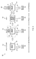
- Fig 3 illustrates how during a life cycle of an apparatus 10 the identification/tracking of the apparatus may be switched on and off by attaching and detaching a battery 6. Attaching the battery 6 disables the RFID tag 4 and detaching the battery re-enables the RFID tag 4.
- a manufacturer creates an apparatus 10 by assembling components including the RFID tag 4 into a permanent assembly 2 of components. Permanent in this sense means that a user should not and typically cannot without special tools disassemble the permanent assembly 2 of components.
- the apparatus 10 is in the first configuration ( Fig 1A ) and the RFID tag 4 has the first operational characteristics. Identification and tracking of the apparatus 10 is enabled.
- a distributor or seller bundles the apparatus 10 with the additional precursor component 6 which in this example is a battery.
- a package 45 will include the apparatus 10 and the battery 6.
- the apparatus 10 is in the first configuration ( Fig 1A ) and identification and tracking of the apparatus 10 (and package 45) is enabled.
- the distributor or seller provides to a user the apparatus 10, the battery and instructions or guidance for assembly of the battery 6 with the permanent assembly 2 of components so that it is part of the apparatus 10 and also for disassembly of the battery 6 from the assembly of components 2 so that it is not part of the apparatus.
- a user or an operator at the point of sale assembles the battery 6 with the permanent assembly 2 to create a temporary assembly of components.
- This converts the apparatus 10 from the first configuration to the second configuration.
- the apparatus 10 in the first configuration is not usable by a user but the apparatus in the second configuration is usable by a user.
- Temporary in this sense means that a user should and typically can without special tools disassemble the battery 6 from the assembly.
- the RFID tag 4 has the second operational characteristics. Identification and tracking of the apparatus 10 by a third party are disabled. The privacy of the user is therefore protected.
- an after sales technician disassembles the battery 6 from the apparatus 10 to convert the apparatus from the second configuration to the first configuration.
- the RFID tag 4 has the first operational characteristics. Identification and tracking of the apparatus 10 are re-enabled. The technician can therefore easily identify characteristics of the apparatus by accessing the tag content or a database using an identifier received from the RFID tag 4.
- the after sales technician may return the apparatus 10 to the user 46 who assembles the battery 6 with the permanent assembly 2 to create a temporary assembly of components. This converts the apparatus 10 from the first configuration to the second configuration. In the second configuration ( Fig 1B ) the RFID tag 4 has the second operational characteristics. Identification and tracking of the apparatus 10 by a third party are disabled. The privacy of the user is therefore protected.
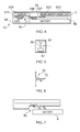
- Fig 4 schematically illustrates an apparatus 10 in the second configuration.
- the permanent assembly 2 of components comprises a printed wiring board (PWB) 50 carrying the RFID tag 4 and further functional components 52A, 52B ....
- the further functional components include a display 52A, display driver circuitry 52B, user input device 52C, audio output device 52D, processing circuitry 52E, memory circuitry 52F and, in this example, cellular transceiver circuitry 52G.
- the RFID tag 4 is positioned within a battery compartment or bay 54 in a housing 58, whereas the cellular transceiver circuitry 52G is positioned remotely from the battery bay 54.
- the RFID tag 4 may optionally also be positioned adjacent a conductive element 56 associated with the PWB 50.
- the conductive element 56 may be, for example, metallization used to enable the PWB 50 to operate as a ground plane for the cellular transceiver circuitry 52F..
- the conductive element 56 may be useful with some but not necessarily all RFID tags.
- the conductive element 56 may, in particular, be useful with RFID tags that operate at certain frequencies.
- a battery 6 typically comprises metal or a metal casing, when a battery 6 is positioned within the battery bay 54 the RFID tag 4 is positioned between the conductive battery 6 and the conductive element 56 and in very close physical proximity to both. The conductive battery 6 and the conductive element 56 interfere with the reception of radio frequency signals 22 by the RFID tag 4.
- RFID tag 4 has first operational characteristics in the absence of a battery 6 in the battery bay 54. However, the presence of a battery 6 in the battery bay interferes with the reception of radio frequency signals 22 by the RFID tag 4 and results in the RFID tag 4 having second operational characteristics.
- Fig 5 schematically illustrates an example of an RFID tag 4 which is configured to have variable operational characteristics.
- a switch 60 is used to modify the RFID tag 4 and adapt its operational characteristics.
- the switch 60 is used to connect/disconnect RFID circuitry 62 from an antenna 64.
- the switch 60 is closed automatically to connect the RFID circuitry 62 and antenna 64 when the apparatus is in the first configuration and is opened automatically to disconnect the RFID circuitry 62 and antenna 64 when the apparatus is in the second configuration.
- the switch 60 may be an electrical switch 70.
- Fig 6 illustrates an n-channel depletion mode field effect transistor (FET) which could be placed so that its channel is in series with the antenna 64 and RFID circuitry 62.
- FET field effect transistor
- the quiescent state absence of a voltage on the gate 72
- a positive voltage on the gate 72 of the FET 70 (provided by the battery 6 when it is present) switches the transistor off and disables the RFID tag 4.
- the electrical switch 70 is opened by the charge of the battery.
- the charge of the battery may be sufficient to operate such an electrical switch even when the charge is insufficient for operation of the apparatus 10.
- the switch 60 may be a physical switch 80 as illustrated in Fig 7 .
- a resiliently movable actuator 82 extends into a battery bay 54 in a housing 58 of the apparatus 10. When a battery 6 is positioned in the battery bay 54, the actuator is depressed against a bias and the switch 60 is opened. When the battery 6 is removed from the battery bay 54, the actuator returns to its equilibrium position under the bias and the switch 60 is closed.
- an RFID tag 4 with a switch 60 in the embodiment illustrated in Fig 4 .
- the switch 60 when operative and actuated, disables the RFID tag 4 by preventing its operation.
- the presence of the battery 6 in the battery compartment disables the RFID tag 4 by diminishing its efficiency and reduces the range of operation of the RFID tag 4 but does not necessarily prevent its operation. This provides a fail safe mechanism that disables the RFID tag 4 even if the switch 60 is inoperative.
- the blocks illustrated in Fig 2 may represent steps in a method.
- the illustration of a particular order to the blocks does not necessarily imply that there is a required or preferred order for the blocks and the order and arrangement of the block may be varied. Furthermore, it may be possible for some steps to be omitted.
- an apparatus comprising:
- the battery may be attachable and detachable from the assembly of components and detachment of the battery from the assembly of components may convert the operation of the radio frequency identification tag.
- Changing the configuration of the apparatus by assembling the battery with the assembly of components may enable use of the apparatus as a mobile functioning electronic device.
- radio frequency identification of the apparatus via the radio frequency identification tag by a reader at a first distance may be enabled and when the radio frequency tag is not fully operational, radio frequency identification of the apparatus via the radio frequency identification tag by the reader at the first distance may be disabled.
- the battery may be configured to interfere, when assembled as a part of the assembly of components, with the reception of radio frequency signals by the radio frequency identification tag.
- the battery may comprise electrically conductive material and may be configured such that the electrically conductive material is in close physical proximity to the radio frequency identification tag when the battery is assembled as a part of the assembly of components.
- the radio frequency tag may be mounted on a printed wiring board
- the battery may be configured such that the radio frequency identification tag is positioned between the electrically conductive material of the battery and an electrically conductive element when the battery is assembled as a part of the assembly of components.
- the apparatus may further comprise a switch that is actuated by the assembly of the battery with the assembly of components and actuation of the switch may modify the radio frequency identification tag.
- the switch may be a physical switch which moves to modify the radio frequency identification tag.
- the switch may be an electrical switch, actuated by the battery, that modifies the radio frequency identification tag.
- the switch may be an integral part of the radio frequency identification tag.
- the apparatus may be a mobile personal electronic device.
- an apparatus comprising:
- the switch may be actuated by the assembly of the battery with the assembly of components and actuation of the switch may modify the radio frequency identification tag.
- the switch may be a physical switch which moves to modify the radio frequency identification tag.
- the switch may be an electrical switch, actuated by the battery, that modifies the radio frequency identification tag.
- the switch may be an integral part of the radio frequency identification tag.
- an apparatus comprising:
- the radio frequency tag may be mounted on a printed wiring board
- the method may further comprise providing for disassembly of the battery from the assembly of components and the consequent enablement of the radio frequency identification tag.
- the method may further comprise enabling the radio frequency identification tag by disassembling the battery from the assembly of components comprising the radio frequency identification tag.
- an apparatus comprising:
- the first operational characteristics may enable radio frequency identification of the apparatus via the radio frequency identification tag by a reader at a first distance and the second operational characteristics may disable radio frequency identification of the apparatus via the radio frequency identification tag by the reader at the first distance.
- the additional component may be attachable and detachable from the assembly of components and detachment of the battery from the assembly of components may convert the apparatus from the second configuration to the first configuration, and may improves the performance of the radio frequency identification tag.
- the additional component may be configured to modify the operational characteristics of the radio frequency identification tag, when assembled as a part of the assembly of components, by interfering with the reception of radio frequency signals by the radio frequency identification tag.
- the apparatus may further comprise a switch that is actuated by the assembly of the additional component with the assembly of components and actuation of the switch may modify the radio frequency identification tag.
Landscapes
- Engineering & Computer Science (AREA)
- Computer Hardware Design (AREA)
- Physics & Mathematics (AREA)
- Theoretical Computer Science (AREA)
- General Physics & Mathematics (AREA)
- Microelectronics & Electronic Packaging (AREA)
- General Engineering & Computer Science (AREA)
- Computer Security & Cryptography (AREA)
- Electromagnetism (AREA)
- Power Engineering (AREA)
- Telephone Function (AREA)
- Burglar Alarm Systems (AREA)
- Near-Field Transmission Systems (AREA)
- Radar Systems Or Details Thereof (AREA)
- Battery Mounting, Suspending (AREA)
Abstract
an assembly of components;
a radio frequency identification tag; and
a switch configured to reduce the performance of the radio frequency identification tag automatically when a battery is assembled with the assembly of components.
Description
- Embodiments of the present invention relate to apparatuses and methods relating to radio frequency identification (RFID) tags.
- A radio frequency identification (RFID) tag is a radio frequency transponder that automatically responds to receipt of a radio frequency inquiry signal with a radio frequency response signal that identifies the RFID tag.
- An RFID tag may be permanently assembled into an apparatus at manufacture to enable identification of the apparatus and enable tracking of the apparatus as it is manufactured, distributed and sold.
- According to various, but not necessarily all, embodiments of the invention there is provided an apparatus comprising: an assembly of components; an additional component that is not part of the assembly of components and is configured for assembly by a user of the apparatus with the assembly of components; and a radio frequency identification tag arranged to have operational characteristics that are automatically dependent upon whether the additional component is assembled as a part of the assembly of components, wherein the apparatus has a first configuration in which the additional component is not part of the assembly of components, the apparatus is unusable by the user and the radio frequency identification tag has first operational characteristics and the apparatus has a second configuration in which the additional component is assembled as a part of the assembly of components, the apparatus is usable by the user and the radio frequency identification tag has second operational characteristics.
- The assembly of components may, for example, be created at a factory and the additional component may be bundled with the assembly of components in a package for distribution or sale or sold separately. At or after the point of sale, the additional component is assembled with the assembly of components to create a working apparatus. Thus a physical component that is necessary to create a working apparatus is used to alter the characteristics of the radio frequency identification tag.
- The first operational characteristics enable radio frequency identification of the apparatus via the radio frequency identification tag by a reader at a first distance and the second operational characteristics disable radio frequency identification of the apparatus via the radio frequency identification tag by the reader at the first distance.
- The modification of the characteristics of the radio frequency identification tag on assembling the apparatus may reduce the performance of the identification tag. This protects the privacy of a user.
- The additional component may be attachable and detachable from the assembly of components. Detachment of the additional component from the assembly of components may improve the performance of the radio frequency identification tag. It may, for example, restore the first operational characteristics.
- The additional component may be a battery or another component that is assembled with the assembly of components to create a working apparatus. It could, for example, be a portion of a housing of the apparatus such as an attachable and detachable cover. It could, for example, be a module such as a smart card, subscriber identity module, user identity module, or memory card.
- According to various, but not necessarily all, embodiments of the invention there is provided an apparatus comprising: an assembly of components; a battery that is not part of the assembly of components and is configured for assembly by a user of the apparatus with the assembly of components; and a radio frequency identification tag arranged to have operational characteristics automatically dependent upon whether the battery is assembled with the assembly of components, wherein the apparatus has a first configuration in which the battery is not assembled with the assembly of components and the radio frequency identification tag is fully operational and the apparatus has a second configuration in which the battery is assembled with the assembly of components and the radio frequency identification tag is not fully operational.
- The assembly of components may, for example, be created at a factory and the battery may be bundled with the assembly of components in a package for distribution or sale or sold separately. Before the user uses the apparatus, for example, at or after the point of sale, the battery must be assembled with the assembly of components to create a working apparatus, such as, for example, a mobile functional electronic device. Thus a physical component that is necessary to create a working apparatus may be used to vary the performance of the radio frequency identification tag.
- The battery may be attachable and detachable from the assembly of components. The detachment of the battery from the assembly of components improves the operation of the radio frequency identification tag. It may, for example, restore the first operational characteristics.
- When the radio frequency tag is fully operational radio frequency identification of the apparatus via the radio frequency identification tag by a reader at a first distance is enabled and when the radio frequency tag is not fully operational radio frequency identification of the apparatus via the radio frequency identification tag by a reader at a first distance is disabled.
- The modification of the characteristics of the radio frequency identification tag on assembling the apparatus may reduce the performance of the identification tag. This protects the privacy of a user.
- The battery may be configured so that when it is assembled as a part of the assembly of components, it interferes with the reception of radio frequency signals by the radio frequency identification tag.
- The battery may comprise electrically conductive material and may be configured such that the electrically conductive material is in close physical proximity to the radio frequency identification tag when the battery is assembled as a part of the assembly of components.
- The radio frequency identification tag may be positioned between the electrically conductive material of the battery and an electrically conductive element when the battery is assembled as a part of the assembly of components.
- The apparatus may comprise a switch that is actuated by the assembly of the battery with the assembly of components and which modifies the radio frequency identification tag.
- The switch may be a physical switch which moves to modify the radio frequency identification tag.
- The switch may be an electrical switch, actuated by the battery, that modifies the radio frequency identification tag.
- The switch may be an integral part of the radio frequency identification tag
- According to various, but not necessarily all, embodiments of the invention there is provided a method comprising: providing an assembly of components comprising a radio frequency identification tag; providing a battery that is not part of the assembly of components and is configured for assembly by a user of the apparatus with the assembly of components; and providing for assembly of the battery with the assembly of components and the consequent disablement of the radio frequency identification tag.
- The method may also comprise providing for disassembly of the battery from the assembly of components and the consequent enablement of the radio frequency identification tag.
- According to various, but not necessarily all, embodiments of the invention there is provided a method comprising: disabling a radio frequency identification tag by assembling a battery with an assembly of components comprising the radio frequency identification tag.
- According to various, but not necessarily all, embodiments of the invention there is provided a method comprising: enabling a radio frequency identification tag by disassembling a battery from an assembly of components comprising the radio frequency identification tag.
- According to various, but not necessarily all, embodiments of the invention there is provided an apparatus comprising: an assembly of components; a radio frequency identification tag; and a switch configured to reduce the performance of the radio frequency identification tag automatically when a battery is assembled with the assembly of components.
- According to various, but not necessarily all, embodiments of the invention there is provided an apparatus comprising: an assembly of components including a housing; a battery bay for receiving a battery; and a radio frequency identification tag positioned within the battery bay and adjacent a conductive element, such that when a battery is present in the battery bay, the radio frequency identification tag is positioned between the battery and the conductive element.
- For a better understanding of various examples of embodiments of the present invention reference will now be made by way of example only to the accompanying drawings in which:
-
Fig 1A schematically illustrates an apparatus in a first configuration in which an additional component is not part of an assembly of components; -
Fig 1B schematically illustrates the apparatus in a second configuration in which the additional component is assembled as part of the assembly of components; -
Fig 2 schematically illustrates one method for controlling the operational characteristics of the RFID tag by assembling and disassembling an attachable/detachable precursor component; -
Fig 3 illustrates how during a life cycle of an apparatus the identification/tracking of the apparatus may be switched on and off by attaching and detaching a battery; -
Fig 4 schematically illustrates an apparatus in the second configuration where the battery interferes with the operation of the radio frequency identification tag; -
Fig 5 schematically illustrates an example of an RFID tag where a switch modifies the RFID tag and adapts its operational characteristics; -
Fig 6 illustrates an electric switch; and -
Fig 7 illustrates a physical electric switch. -
Fig 1A schematically illustrates anapparatus 10 in a first configuration in which anadditional component 6 is not part of anassembly 2 of components.Fig 1B schematically illustrates theapparatus 10 in a second configuration in which theadditional component 6 is assembled as part of theassembly 2 of components. - The
assembly 2 of components comprises a radio frequency identification (RFID)tag 4. AnRFID tag 4 is a radio frequency transponder that automatically responds to receipt of a radiofrequency inquiry signal 22 with a radiofrequency response signal 24. AnRFID tag 4 is typically permanently assembled into theapparatus 10 at manufacture and may be used to identify and track theapparatus 10. - The
RFID tag 4 may be passive or active. A passive tag does not have its own battery but uses the energy of the receivedinquiry signal 22 to power theresponse signal 24. Examples of passive RFID tags are defined by, for example, the standards ISO 14443, Electronic Product Code (EPC) and ISO 18000-6. An active RFID tag has its own long-life battery. - The range of an
RFID tag 4 is dependent upon the power output of areader device 20 that produces theinquiry signal 22 and the type ofRFID tag 4. The power of thereader 20 may be limited by law, for example, to 1W. Passive RFID tags have a range of a few cms to tens of meters although work is ongoing to extend this range. Active RFID tags can have a greater range. When tags operating at higher frequencies are used the range can be increased. - The
apparatus 10 may be an electronic device that is mobile (moves with a person) or portable (carried by a person) and that is personal (used exclusively or predominantly by an individual). The identification or tracking of anapparatus 10 that is personal and mobile/portable would enable the tracking of an individual. - The
RFID tag 4 is arranged to have operational characteristics that are automatically dependent upon whether theadditional component 6 is assembled as a part of theassembly 2 of components. The modification of the characteristics of theRFID tag 4 may disable third party tracking of theapparatus 10 while it is in the possession of an individual user. This protects the privacy of a user. - The
additional component 6 is a 'precursor' component. A precursor component is a component that is assembled with theassembly 2 of components before theapparatus 10 is usable. It is typically a functional component that provides a necessary function to theapparatus 10 in addition to modifying the operational characteristics of theRFID tag 4. In the illustrated examples theadditional component 6 is a battery that provides power to theapparatus 10. However, in other embodiments, theadditional component 6 may be another precursor component that is assembled with theassembly 2 of components to create a workingapparatus 10. It could, for example, be a necessary portion of a housing of the apparatus such as an attachable and detachable cover. It could, for example, be a necessary additional electronic peripheral component such as a smart card, subscriber identity module, user identity module, or memory card. - Referring to
Fig 1A , theapparatus 10 is in a first configuration in which theadditional component 6 is not part of theassembly 2 of components. Theapparatus 10 is unusable by the user and the radiofrequency identification tag 4 has first operational characteristics. The first operational characteristics enable theRFID tag 4 to receive a radiofrequency inquiry signal 22 from areader device 20 at a distance d and automatically respond with a radiofrequency response signal 24 that includes reply data. The reply data may identify theRFID tag 4. It may for example be a Unique ID number (UID) that is returned in the first reply to an interrogation from a reader. TheRFID tag 4 may also include a memory and the reply data may be read from the memory and include one or more of production serial numbers, International mobile equipment identifier (IMEI) if theapparatus 10 is a mobile communication device, and other production and service data such as version, batch, date, time or anything else which helps later servicing. The data may be in plain text or encrypted, or simply as a sequence that is only meaningful to the apparatus manufacturer such as line number, batch, shipping number etc. - The
RFID tag 4 is arranged to have operational characteristics that are automatically dependent upon whether theadditional component 6 is assembled as a part of theassembly 2 of components. The modification of the characteristics of theRFID tag 4 may reduce the performance of theRFID tag 4. This protects the privacy of a user. - Referring to
Fig 1B , theapparatus 10 is in the second configuration in which theadditional component 6 is part of theassembly 2 of components. Theapparatus 10 is usable by the user and theRFID tag 4 has second operational characteristics. In this example, the second operational characteristics disable theRFID tag 4 from responding to a radiofrequency inquiry signal 22 sent from thereader device 20 at the distance d. -
Fig 2 schematically illustrates onemethod 30 for controlling the operational characteristics of theRFID tag 4 by assembling and disassembling an attachable/detachable precursor component 6. - Initially at
step 32, the additional precursor component 6 (e.g. the battery) is separate from theapparatus 10 and theapparatus 10 is in the first configuration (Fig 1A ). Remote identification (and tracking) of theapparatus 10 is enabled. - When at
step 34 theprecursor component 6 is assembled with theassembly 2 of components to enable an individual user to use theapparatus 10, theapparatus 10 changes from the first configuration (Fig 1A ) to the second configuration (Fig 1B ) and, in this example, remote identification (and tracking) of theapparatus 10 is disabled atstep 36. - When at
step 38 theprecursor component 6 is disassembled from theassembly 2 of components, theapparatus 10 changes from the second configuration (Fig 1B ) to the first configuration (Fig 1A ) and, in this example, remote identification (and tracking) of theapparatus 10 is re-enabled atstep 32. -
Fig 3 illustrates how during a life cycle of anapparatus 10 the identification/tracking of the apparatus may be switched on and off by attaching and detaching abattery 6. Attaching thebattery 6 disables theRFID tag 4 and detaching the battery re-enables theRFID tag 4. - At
stage 42, a manufacturer creates anapparatus 10 by assembling components including theRFID tag 4 into apermanent assembly 2 of components. Permanent in this sense means that a user should not and typically cannot without special tools disassemble thepermanent assembly 2 of components. At this stage theapparatus 10 is in the first configuration (Fig 1A ) and theRFID tag 4 has the first operational characteristics. Identification and tracking of theapparatus 10 is enabled. - At
stage 44, a distributor or seller bundles theapparatus 10 with theadditional precursor component 6 which in this example is a battery. Typically apackage 45 will include theapparatus 10 and thebattery 6. At this stage theapparatus 10 is in the first configuration (Fig 1A ) and identification and tracking of the apparatus 10 (and package 45) is enabled. - The distributor or seller provides to a user the
apparatus 10, the battery and instructions or guidance for assembly of thebattery 6 with thepermanent assembly 2 of components so that it is part of theapparatus 10 and also for disassembly of thebattery 6 from the assembly ofcomponents 2 so that it is not part of the apparatus. - At
stage 46, a user or an operator at the point of sale assembles thebattery 6 with thepermanent assembly 2 to create a temporary assembly of components. This converts theapparatus 10 from the first configuration to the second configuration. Theapparatus 10 in the first configuration is not usable by a user but the apparatus in the second configuration is usable by a user. Temporary in this sense means that a user should and typically can without special tools disassemble thebattery 6 from the assembly. When theapparatus 10 is in the second configuration (Fig 1B ) theRFID tag 4 has the second operational characteristics. Identification and tracking of theapparatus 10 by a third party are disabled. The privacy of the user is therefore protected. - At
stage 48, an after sales technician disassembles thebattery 6 from theapparatus 10 to convert the apparatus from the second configuration to the first configuration. In the first configuration (Fig 1A ) theRFID tag 4 has the first operational characteristics. Identification and tracking of theapparatus 10 are re-enabled. The technician can therefore easily identify characteristics of the apparatus by accessing the tag content or a database using an identifier received from theRFID tag 4. - The after sales technician may return the
apparatus 10 to theuser 46 who assembles thebattery 6 with thepermanent assembly 2 to create a temporary assembly of components. This converts theapparatus 10 from the first configuration to the second configuration. In the second configuration (Fig 1B ) theRFID tag 4 has the second operational characteristics. Identification and tracking of theapparatus 10 by a third party are disabled. The privacy of the user is therefore protected. -
Fig 4 schematically illustrates anapparatus 10 in the second configuration. In this example, thepermanent assembly 2 of components comprises a printed wiring board (PWB) 50 carrying theRFID tag 4 and furtherfunctional components display 52A,display driver circuitry 52B,user input device 52C,audio output device 52D, processingcircuitry 52E,memory circuitry 52F and, in this example,cellular transceiver circuitry 52G. - The
RFID tag 4 is positioned within a battery compartment orbay 54 in ahousing 58, whereas thecellular transceiver circuitry 52G is positioned remotely from thebattery bay 54. - The
RFID tag 4 may optionally also be positioned adjacent aconductive element 56 associated with thePWB 50. Theconductive element 56 may be, for example, metallization used to enable thePWB 50 to operate as a ground plane for thecellular transceiver circuitry 52F.. Theconductive element 56 may be useful with some but not necessarily all RFID tags. Theconductive element 56 may, in particular, be useful with RFID tags that operate at certain frequencies. - A
battery 6 typically comprises metal or a metal casing, when abattery 6 is positioned within thebattery bay 54 theRFID tag 4 is positioned between theconductive battery 6 and theconductive element 56 and in very close physical proximity to both. Theconductive battery 6 and theconductive element 56 interfere with the reception of radio frequency signals 22 by theRFID tag 4. -
RFID tag 4 has first operational characteristics in the absence of abattery 6 in thebattery bay 54. However, the presence of abattery 6 in the battery bay interferes with the reception of radio frequency signals 22 by theRFID tag 4 and results in theRFID tag 4 having second operational characteristics. -
Fig 5 schematically illustrates an example of anRFID tag 4 which is configured to have variable operational characteristics. In this example, aswitch 60 is used to modify theRFID tag 4 and adapt its operational characteristics. - In the illustrated example, the
switch 60 is used to connect/disconnect RFID circuitry 62 from anantenna 64. Theswitch 60 is closed automatically to connect theRFID circuitry 62 andantenna 64 when the apparatus is in the first configuration and is opened automatically to disconnect theRFID circuitry 62 andantenna 64 when the apparatus is in the second configuration. - The
switch 60 may be anelectrical switch 70. -
Fig 6 illustrates an n-channel depletion mode field effect transistor (FET) which could be placed so that its channel is in series with theantenna 64 andRFID circuitry 62. In the quiescent state (absence of a voltage on the gate 72) the transistor is on. A positive voltage on thegate 72 of the FET 70 (provided by thebattery 6 when it is present) switches the transistor off and disables theRFID tag 4. Thus theelectrical switch 70 is opened by the charge of the battery. The charge of the battery may be sufficient to operate such an electrical switch even when the charge is insufficient for operation of theapparatus 10. - The
switch 60 may be aphysical switch 80 as illustrated inFig 7 . A resilientlymovable actuator 82 extends into abattery bay 54 in ahousing 58 of theapparatus 10. When abattery 6 is positioned in thebattery bay 54, the actuator is depressed against a bias and theswitch 60 is opened. When thebattery 6 is removed from thebattery bay 54, the actuator returns to its equilibrium position under the bias and theswitch 60 is closed. - It is of course possible to use a switch arrangement in which a physical switch and an electrical switch are positioned in series so that if either one of the electrical or physical switches is open the switching arrangement is open. This provides a fail safe mechanism so that the
RFID tag 4 is disabled if one or both of theelectrical switch 70 andphysical switch 80 are actuated. - It is possible to provide an
RFID tag 4 with aswitch 60 in the embodiment illustrated inFig 4 . Theswitch 60, when operative and actuated, disables theRFID tag 4 by preventing its operation. The presence of thebattery 6 in the battery compartment disables theRFID tag 4 by diminishing its efficiency and reduces the range of operation of theRFID tag 4 but does not necessarily prevent its operation. This provides a fail safe mechanism that disables theRFID tag 4 even if theswitch 60 is inoperative. - The blocks illustrated in
Fig 2 may represent steps in a method. The illustration of a particular order to the blocks does not necessarily imply that there is a required or preferred order for the blocks and the order and arrangement of the block may be varied. Furthermore, it may be possible for some steps to be omitted. - Although embodiments of the present invention have been described in the preceding paragraphs with reference to various examples, it should be appreciated that modifications to the examples given can be made without departing from the scope of the invention as claimed.
- Features described in the preceding description may be used in combinations other than the combinations explicitly described.
- Although functions have been described with reference to certain features, those functions may be performable by other features whether described or not.
- Although features have been described with reference to certain embodiments, those features may also be present in other embodiments whether described or not.
- Whilst endeavoring in the foregoing specification to draw attention to those features of the invention believed to be of particular importance it should be understood that the Applicant claims protection in respect of any patentable feature or combination of features hereinbefore referred to and/or shown in the drawings whether or not particular emphasis has been placed thereon.
- According to some examples, but not necessarily all examples, there is provided an apparatus comprising:
- an assembly of components;
- a battery that is not part of the assembly of components and is configured for assembly by a user of the apparatus with the assembly of components; and a radio frequency identification tag arranged to have operational characteristics automatically dependent upon whether the battery is assembled with the assembly of components,
- wherein the apparatus has a first configuration in which the battery is not assembled with the assembly of components and the radio frequency identification tag is fully operational and the apparatus has a second configuration in which the battery is assembled with the assembly of components and the radio frequency identification tag is not fully operational.
- The battery may be attachable and detachable from the assembly of components and detachment of the battery from the assembly of components may convert the operation of the radio frequency identification tag.
- Changing the configuration of the apparatus by assembling the battery with the assembly of components may enable use of the apparatus as a mobile functioning electronic device.
- When the radio frequency tag is fully operational, radio frequency identification of the apparatus via the radio frequency identification tag by a reader at a first distance may be enabled and when the radio frequency tag is not fully operational, radio frequency identification of the apparatus via the radio frequency identification tag by the reader at the first distance may be disabled.
- The battery may be configured to interfere, when assembled as a part of the assembly of components, with the reception of radio frequency signals by the radio frequency identification tag.
- The battery may comprise electrically conductive material and may be configured such that the electrically conductive material is in close physical proximity to the radio frequency identification tag when the battery is assembled as a part of the assembly of components.
- The radio frequency tag may be mounted on a printed wiring board
- The battery may be configured such that the radio frequency identification tag is positioned between the electrically conductive material of the battery and an electrically conductive element when the battery is assembled as a part of the assembly of components.
- The apparatus may further comprise a switch that is actuated by the assembly of the battery with the assembly of components and actuation of the switch may modify the radio frequency identification tag.
- The switch may be a physical switch which moves to modify the radio frequency identification tag.
- The switch may be an electrical switch, actuated by the battery, that modifies the radio frequency identification tag.
- The switch may be an integral part of the radio frequency identification tag.
- The apparatus may be a mobile personal electronic device.
- According to some examples, but not necessarily all examples, there is provided an apparatus comprising:
- an assembly of components;
- a radio frequency identification tag; and
- a switch configured to reduce the performance of the radio frequency identification tag automatically when a battery is assembled with the assembly of components.
- The switch may be actuated by the assembly of the battery with the assembly of components and actuation of the switch may modify the radio frequency identification tag.
- The switch may be a physical switch which moves to modify the radio frequency identification tag.
- The switch may be an electrical switch, actuated by the battery, that modifies the radio frequency identification tag.
- The switch may be an integral part of the radio frequency identification tag.
- According to some examples, but not necessarily all examples, there is provided an apparatus comprising:
- an assembly of components including a housing;
- a battery bay for receiving a battery; and
- a radio frequency identification tag positioned within the battery bay and adjacent a conductive element, such that when a battery is present in the battery bay, the radio frequency identification tag is positioned between the battery and the conductive element.
- The radio frequency tag may be mounted on a printed wiring board
- According to some examples, but not necessarily all examples, there is provided a method comprising:
- providing an assembly of components comprising a radio frequency identification tag;
- providing a battery that is not part of the assembly of components and is configured for assembly by a user of the apparatus with the assembly of components; and
- providing for assembly of the battery with the assembly of components and the consequent disablement of the radio frequency identification tag.
- The method may further comprise providing for disassembly of the battery from the assembly of components and the consequent enablement of the radio frequency identification tag.
- According to some examples, but not necessarily all examples, there is provided a method comprising:
- disabling a radio frequency identification tag by assembling a battery with an an assembly of components comprising the radio frequency identification tag.
- The method may further comprise enabling the radio frequency identification tag by disassembling the battery from the assembly of components comprising the radio frequency identification tag.
- According to some examples, but not necessarily all examples there is provided a method comprising:
- enabling a radio frequency identification tag by disassembling a battery from an assembly of components comprising the radio frequency identification tag.
- According to some examples but not necessarily all examples there is provided an apparatus comprising:
- an assembly of components;
- an additional component that is not part of the assembly of components and is configured for assembly by a user of the apparatus with the assembly of components; and
- a radio frequency identification tag arranged to have operational characteristics that are automatically dependent upon whether the additional component is assembled as a part of the assembly of components,
- wherein the apparatus has a first configuration in which the additional component is not part of the assembly of components, the apparatus is unusable by the user and the radio frequency identification tag has first operational characteristics and the apparatus has a second configuration in which the additional component is assembled as a part of the assembly of components, the apparatus is usable by the user and the radio frequency identification tag has second operational characteristics.
- The first operational characteristics may enable radio frequency identification of the apparatus via the radio frequency identification tag by a reader at a first distance and the second operational characteristics may disable radio frequency identification of the apparatus via the radio frequency identification tag by the reader at the first distance.
- The additional component may be attachable and detachable from the assembly of components and detachment of the battery from the assembly of components may convert the apparatus from the second configuration to the first configuration, and may improves the performance of the radio frequency identification tag.
- The additional component may be configured to modify the operational characteristics of the radio frequency identification tag, when assembled as a part of the assembly of components, by interfering with the reception of radio frequency signals by the radio frequency identification tag.
- The apparatus may further comprise a switch that is actuated by the assembly of the additional component with the assembly of components and actuation of the switch may modify the radio frequency identification tag.
Claims (12)
- An apparatus comprising:an assembly of components;a radio frequency identification tag; anda switch configured to reduce the performance of the radio frequency identification tag automatically when a battery is assembled with the assembly of components.
- An apparatus as claimed in claim 1, wherein the switch is actuated by the assembly of the battery with the assembly of components and wherein actuation of the switch modifies the radio frequency identification tag.
- An apparatus as claimed in claim 1 or 2, wherein the switch is a physical switch which moves to modify the radio frequency identification tag.
- An apparatus as claimed in claim 1 or 2, wherein the switch is an electrical switch, actuated by the battery, that modifies the radio frequency identification tag.
- An apparatus as claimed in any preceding claim, wherein the switch is an integral part of the radio frequency identification tag.
- An apparatus as claimed in any preceding claim, wherein the apparatus is a mobile personal electronic device.
- A method comprising:providing an assembly of components comprising a radio frequency identification tag and a switch configured to reduce the performance of the radio frequency identification tag automatically when a battery is assembled with the assembly of components;providing a battery that is not part of the assembly of components and is configured for assembly by a user of the apparatus with the assembly of components; andproviding for assembly of the battery with the assembly of components andthe consequent disablement of the radio frequency identification tag.
- A method as claimed in claim 7, further comprising providing for disassembly of the battery from the assembly of components and the consequent enablement of the radio frequency identification tag.
- A method as claimed in claim 7 or 8, wherein the switch is a physical switch which moves to modify the radio frequency identification tag.
- A method as claimed in claim 7 or 8, wherein the switch is an electrical switch, actuated by the battery, that modifies the radio frequency identification tag.
- A method as claimed in any of claims 7 to 10, wherein the switch is an integral part of the radio frequency identification tag.
- A method as claimed in any of claims 7 to 11, wherein the assembly of components and the battery form at least part of a mobile personal electronic device.
Priority Applications (1)
| Application Number | Priority Date | Filing Date | Title |
|---|---|---|---|
| EP13171736.5A EP2662808B1 (en) | 2008-06-09 | 2008-06-09 | Apparatuses and methods relating to radio frequency identification (RFID) tags |
Applications Claiming Priority (3)
| Application Number | Priority Date | Filing Date | Title |
|---|---|---|---|
| PCT/EP2008/057183 WO2009149746A1 (en) | 2008-06-09 | 2008-06-09 | Apparatuses and methods relating to radio frequency identification (rfid) tags |
| EP08760747.9A EP2297679B1 (en) | 2008-06-09 | 2008-06-09 | Apparatuses and methods relating to radio frequency identification (rfid) tags |
| EP13171736.5A EP2662808B1 (en) | 2008-06-09 | 2008-06-09 | Apparatuses and methods relating to radio frequency identification (RFID) tags |
Related Parent Applications (2)
| Application Number | Title | Priority Date | Filing Date |
|---|---|---|---|
| EP08760747.9 Division | 2008-06-09 | ||
| EP08760747.9A Division EP2297679B1 (en) | 2008-06-09 | 2008-06-09 | Apparatuses and methods relating to radio frequency identification (rfid) tags |
Publications (3)
| Publication Number | Publication Date |
|---|---|
| EP2662808A2 true EP2662808A2 (en) | 2013-11-13 |
| EP2662808A3 EP2662808A3 (en) | 2013-12-18 |
| EP2662808B1 EP2662808B1 (en) | 2016-07-20 |
Family
ID=40292489
Family Applications (2)
| Application Number | Title | Priority Date | Filing Date |
|---|---|---|---|
| EP08760747.9A Not-in-force EP2297679B1 (en) | 2008-06-09 | 2008-06-09 | Apparatuses and methods relating to radio frequency identification (rfid) tags |
| EP13171736.5A Not-in-force EP2662808B1 (en) | 2008-06-09 | 2008-06-09 | Apparatuses and methods relating to radio frequency identification (RFID) tags |
Family Applications Before (1)
| Application Number | Title | Priority Date | Filing Date |
|---|---|---|---|
| EP08760747.9A Not-in-force EP2297679B1 (en) | 2008-06-09 | 2008-06-09 | Apparatuses and methods relating to radio frequency identification (rfid) tags |
Country Status (3)
| Country | Link |
|---|---|
| US (1) | US8490881B2 (en) |
| EP (2) | EP2297679B1 (en) |
| WO (1) | WO2009149746A1 (en) |
Families Citing this family (4)
| Publication number | Priority date | Publication date | Assignee | Title |
|---|---|---|---|---|
| US20130171967A1 (en) * | 2012-01-04 | 2013-07-04 | Ayman S. Ashour | Providing Secure Execution of Mobile Device Workflows |
| GB2507073B (en) * | 2012-10-17 | 2017-02-01 | China Ind Ltd | Interactive toy |
| US9355545B2 (en) | 2014-05-20 | 2016-05-31 | Dirac Solutions, Inc. | Secure optionally passive RFID tag or sensor with external power source and data logging |
| US11192055B2 (en) | 2017-08-30 | 2021-12-07 | Cummins Filtration Ip, Inc. | Interlock for genuine filter recognition |
Family Cites Families (10)
| Publication number | Priority date | Publication date | Assignee | Title |
|---|---|---|---|---|
| ATE483209T1 (en) * | 2000-05-03 | 2010-10-15 | Gemalto Sa | A CHIP CARD AND A CASE FOR IT |
| GB0229124D0 (en) * | 2002-12-13 | 2003-01-15 | Hills Numberplates Ltd | Signs |
| JP2004227046A (en) | 2003-01-20 | 2004-08-12 | Hitachi Ltd | Portable information equipment |
| US7237719B2 (en) * | 2003-09-03 | 2007-07-03 | Stmicroelectronics, Inc. | Method and apparatus for a USB and contactless smart card device |
| JP2005244852A (en) * | 2004-02-27 | 2005-09-08 | Kyocera Corp | Electronics |
| JP2006053761A (en) * | 2004-08-12 | 2006-02-23 | T Line:Kk | Skimming prevention device |
| JPWO2006134807A1 (en) * | 2005-06-17 | 2009-01-08 | オリエント測器コンピュータ株式会社 | Portable terminal device and skimming prevention device |
| DE102005028407A1 (en) * | 2005-06-20 | 2007-01-11 | Engbert, Aloys, 80636 München | Case for chip card or chip card itself, made of material with shielding effect protecting card from unauthorized reading |
| US7423547B2 (en) * | 2005-09-29 | 2008-09-09 | Lear Corporation | System and method for verifying assembly of manufactured parts using RFID tags |
| US9342777B2 (en) * | 2006-07-06 | 2016-05-17 | Ricoh Company, Ltd. | Programmatic control of RFID tags |
-
2008
- 2008-06-09 EP EP08760747.9A patent/EP2297679B1/en not_active Not-in-force
- 2008-06-09 US US12/995,985 patent/US8490881B2/en not_active Expired - Fee Related
- 2008-06-09 WO PCT/EP2008/057183 patent/WO2009149746A1/en not_active Ceased
- 2008-06-09 EP EP13171736.5A patent/EP2662808B1/en not_active Not-in-force
Non-Patent Citations (1)
| Title |
|---|
| None |
Also Published As
| Publication number | Publication date |
|---|---|
| US20110139881A1 (en) | 2011-06-16 |
| EP2297679B1 (en) | 2013-12-25 |
| EP2297679A1 (en) | 2011-03-23 |
| EP2662808B1 (en) | 2016-07-20 |
| US8490881B2 (en) | 2013-07-23 |
| EP2662808A3 (en) | 2013-12-18 |
| WO2009149746A1 (en) | 2009-12-17 |
Similar Documents
| Publication | Publication Date | Title |
|---|---|---|
| EP2483846B1 (en) | Amplifying radio frequency signals | |
| CN106299677B (en) | Near field communication antenna and near field communication device having the same | |
| WO2007106231A3 (en) | Smart rfid reader antennas | |
| WO2006124433A3 (en) | Radio frequency identification (rfid) system for a forklift | |
| EP2662808B1 (en) | Apparatuses and methods relating to radio frequency identification (RFID) tags | |
| CN108256371B (en) | Portable object comprising a near field communication device | |
| US9215752B2 (en) | Electronic device with through-display near field communication capability | |
| KR20110126235A (en) | Protective case type RDF tag reading device detachable with mobile communication terminal and RDF tag information processing system using same | |
| KR101583093B1 (en) | Method for supporting different types of UICC cards and Terminal therefor | |
| JP2017531893A (en) | Non-contact biometric identification device that allows multiple configurations | |
| US9098789B2 (en) | RFID communication circuit for an electronic device and corresponding methods | |
| US20090128300A1 (en) | Wireless device with an rfid interrogator | |
| CN202257621U (en) | Integrated module compatible with NFC-EPC function | |
| KR100761252B1 (en) | Selection Device of RF Antenna in Mobile Telecommunication Terminal | |
| EP1534022A1 (en) | Method for supporting identification tag based services | |
| DK2388733T3 (en) | Electronic data transmission device with a security module | |
| KR100570518B1 (en) | Mobile communication terminal equipped with RF reading module | |
| US20180046891A1 (en) | Nfc tag having dual mode | |
| KR200401805Y1 (en) | Battery for Mobile Phone Having RF R/W Module | |
| KR200391617Y1 (en) | Selection Device of RF Antenna in Mobile Telecommunication Terminal | |
| US20100285832A1 (en) | electronic apparatus and associated elements and methods | |
| KR100940063B1 (en) | Smart card type RDF reading device and card management method using same | |
| KR20090039453A (en) | Vehicle Insurance Report and Reception System | |
| KR20050088945A (en) | Module battery having uhf rfid tag | |
| KR20120135564A (en) | Rfid tag and pcb of electronic product provided with the rfid tag |
Legal Events
| Date | Code | Title | Description |
|---|---|---|---|
| PUAI | Public reference made under article 153(3) epc to a published international application that has entered the european phase |
Free format text: ORIGINAL CODE: 0009012 |
|
| AC | Divisional application: reference to earlier application |
Ref document number: 2297679 Country of ref document: EP Kind code of ref document: P |
|
| AK | Designated contracting states |
Kind code of ref document: A2 Designated state(s): AT BE BG CH CY CZ DE DK EE ES FI FR GB GR HR HU IE IS IT LI LT LU LV MC MT NL NO PL PT RO SE SI SK TR |
|
| PUAL | Search report despatched |
Free format text: ORIGINAL CODE: 0009013 |
|
| AK | Designated contracting states |
Kind code of ref document: A3 Designated state(s): AT BE BG CH CY CZ DE DK EE ES FI FR GB GR HR HU IE IS IT LI LT LU LV MC MT NL NO PL PT RO SE SI SK TR |
|
| RIC1 | Information provided on ipc code assigned before grant |
Ipc: G06K 19/073 20060101AFI20131111BHEP Ipc: G06K 19/077 20060101ALI20131111BHEP |
|
| 17P | Request for examination filed |
Effective date: 20140325 |
|
| RBV | Designated contracting states (corrected) |
Designated state(s): AT BE BG CH CY CZ DE DK EE ES FI FR GB GR HR HU IE IS IT LI LT LU LV MC MT NL NO PL PT RO SE SI SK TR |
|
| RAP1 | Party data changed (applicant data changed or rights of an application transferred) |
Owner name: NOKIA CORPORATION |
|
| RAP1 | Party data changed (applicant data changed or rights of an application transferred) |
Owner name: NOKIA TECHNOLOGIES OY |
|
| GRAP | Despatch of communication of intention to grant a patent |
Free format text: ORIGINAL CODE: EPIDOSNIGR1 |
|
| INTG | Intention to grant announced |
Effective date: 20160113 |
|
| GRAS | Grant fee paid |
Free format text: ORIGINAL CODE: EPIDOSNIGR3 |
|
| GRAA | (expected) grant |
Free format text: ORIGINAL CODE: 0009210 |
|
| AC | Divisional application: reference to earlier application |
Ref document number: 2297679 Country of ref document: EP Kind code of ref document: P |
|
| AK | Designated contracting states |
Kind code of ref document: B1 Designated state(s): AT BE BG CH CY CZ DE DK EE ES FI FR GB GR HR HU IE IS IT LI LT LU LV MC MT NL NO PL PT RO SE SI SK TR |
|
| REG | Reference to a national code |
Ref country code: GB Ref legal event code: FG4D |
|
| REG | Reference to a national code |
Ref country code: CH Ref legal event code: EP |
|
| REG | Reference to a national code |
Ref country code: IE Ref legal event code: FG4D |
|
| REG | Reference to a national code |
Ref country code: AT Ref legal event code: REF Ref document number: 814619 Country of ref document: AT Kind code of ref document: T Effective date: 20160815 |
|
| REG | Reference to a national code |
Ref country code: DE Ref legal event code: R096 Ref document number: 602008045270 Country of ref document: DE |
|
| REG | Reference to a national code |
Ref country code: NL Ref legal event code: FP |
|
| REG | Reference to a national code |
Ref country code: LT Ref legal event code: MG4D |
|
| REG | Reference to a national code |
Ref country code: AT Ref legal event code: MK05 Ref document number: 814619 Country of ref document: AT Kind code of ref document: T Effective date: 20160720 |
|
| PG25 | Lapsed in a contracting state [announced via postgrant information from national office to epo] |
Ref country code: IS Free format text: LAPSE BECAUSE OF FAILURE TO SUBMIT A TRANSLATION OF THE DESCRIPTION OR TO PAY THE FEE WITHIN THE PRESCRIBED TIME-LIMIT Effective date: 20161120 Ref country code: HR Free format text: LAPSE BECAUSE OF FAILURE TO SUBMIT A TRANSLATION OF THE DESCRIPTION OR TO PAY THE FEE WITHIN THE PRESCRIBED TIME-LIMIT Effective date: 20160720 Ref country code: NO Free format text: LAPSE BECAUSE OF FAILURE TO SUBMIT A TRANSLATION OF THE DESCRIPTION OR TO PAY THE FEE WITHIN THE PRESCRIBED TIME-LIMIT Effective date: 20161020 Ref country code: LT Free format text: LAPSE BECAUSE OF FAILURE TO SUBMIT A TRANSLATION OF THE DESCRIPTION OR TO PAY THE FEE WITHIN THE PRESCRIBED TIME-LIMIT Effective date: 20160720 Ref country code: FI Free format text: LAPSE BECAUSE OF FAILURE TO SUBMIT A TRANSLATION OF THE DESCRIPTION OR TO PAY THE FEE WITHIN THE PRESCRIBED TIME-LIMIT Effective date: 20160720 Ref country code: IT Free format text: LAPSE BECAUSE OF FAILURE TO SUBMIT A TRANSLATION OF THE DESCRIPTION OR TO PAY THE FEE WITHIN THE PRESCRIBED TIME-LIMIT Effective date: 20160720 |
|
| PG25 | Lapsed in a contracting state [announced via postgrant information from national office to epo] |
Ref country code: ES Free format text: LAPSE BECAUSE OF FAILURE TO SUBMIT A TRANSLATION OF THE DESCRIPTION OR TO PAY THE FEE WITHIN THE PRESCRIBED TIME-LIMIT Effective date: 20160720 Ref country code: AT Free format text: LAPSE BECAUSE OF FAILURE TO SUBMIT A TRANSLATION OF THE DESCRIPTION OR TO PAY THE FEE WITHIN THE PRESCRIBED TIME-LIMIT Effective date: 20160720 Ref country code: PL Free format text: LAPSE BECAUSE OF FAILURE TO SUBMIT A TRANSLATION OF THE DESCRIPTION OR TO PAY THE FEE WITHIN THE PRESCRIBED TIME-LIMIT Effective date: 20160720 Ref country code: PT Free format text: LAPSE BECAUSE OF FAILURE TO SUBMIT A TRANSLATION OF THE DESCRIPTION OR TO PAY THE FEE WITHIN THE PRESCRIBED TIME-LIMIT Effective date: 20161121 Ref country code: BE Free format text: LAPSE BECAUSE OF FAILURE TO SUBMIT A TRANSLATION OF THE DESCRIPTION OR TO PAY THE FEE WITHIN THE PRESCRIBED TIME-LIMIT Effective date: 20160720 Ref country code: GR Free format text: LAPSE BECAUSE OF FAILURE TO SUBMIT A TRANSLATION OF THE DESCRIPTION OR TO PAY THE FEE WITHIN THE PRESCRIBED TIME-LIMIT Effective date: 20161021 Ref country code: LV Free format text: LAPSE BECAUSE OF FAILURE TO SUBMIT A TRANSLATION OF THE DESCRIPTION OR TO PAY THE FEE WITHIN THE PRESCRIBED TIME-LIMIT Effective date: 20160720 Ref country code: SE Free format text: LAPSE BECAUSE OF FAILURE TO SUBMIT A TRANSLATION OF THE DESCRIPTION OR TO PAY THE FEE WITHIN THE PRESCRIBED TIME-LIMIT Effective date: 20160720 |
|
| REG | Reference to a national code |
Ref country code: DE Ref legal event code: R097 Ref document number: 602008045270 Country of ref document: DE |
|
| PG25 | Lapsed in a contracting state [announced via postgrant information from national office to epo] |
Ref country code: RO Free format text: LAPSE BECAUSE OF FAILURE TO SUBMIT A TRANSLATION OF THE DESCRIPTION OR TO PAY THE FEE WITHIN THE PRESCRIBED TIME-LIMIT Effective date: 20160720 Ref country code: EE Free format text: LAPSE BECAUSE OF FAILURE TO SUBMIT A TRANSLATION OF THE DESCRIPTION OR TO PAY THE FEE WITHIN THE PRESCRIBED TIME-LIMIT Effective date: 20160720 |
|
| PLBE | No opposition filed within time limit |
Free format text: ORIGINAL CODE: 0009261 |
|
| STAA | Information on the status of an ep patent application or granted ep patent |
Free format text: STATUS: NO OPPOSITION FILED WITHIN TIME LIMIT |
|
| PG25 | Lapsed in a contracting state [announced via postgrant information from national office to epo] |
Ref country code: BG Free format text: LAPSE BECAUSE OF FAILURE TO SUBMIT A TRANSLATION OF THE DESCRIPTION OR TO PAY THE FEE WITHIN THE PRESCRIBED TIME-LIMIT Effective date: 20161020 Ref country code: SK Free format text: LAPSE BECAUSE OF FAILURE TO SUBMIT A TRANSLATION OF THE DESCRIPTION OR TO PAY THE FEE WITHIN THE PRESCRIBED TIME-LIMIT Effective date: 20160720 Ref country code: CZ Free format text: LAPSE BECAUSE OF FAILURE TO SUBMIT A TRANSLATION OF THE DESCRIPTION OR TO PAY THE FEE WITHIN THE PRESCRIBED TIME-LIMIT Effective date: 20160720 Ref country code: DK Free format text: LAPSE BECAUSE OF FAILURE TO SUBMIT A TRANSLATION OF THE DESCRIPTION OR TO PAY THE FEE WITHIN THE PRESCRIBED TIME-LIMIT Effective date: 20160720 |
|
| 26N | No opposition filed |
Effective date: 20170421 |
|
| PG25 | Lapsed in a contracting state [announced via postgrant information from national office to epo] |
Ref country code: SI Free format text: LAPSE BECAUSE OF FAILURE TO SUBMIT A TRANSLATION OF THE DESCRIPTION OR TO PAY THE FEE WITHIN THE PRESCRIBED TIME-LIMIT Effective date: 20160720 |
|
| PG25 | Lapsed in a contracting state [announced via postgrant information from national office to epo] |
Ref country code: MC Free format text: LAPSE BECAUSE OF FAILURE TO SUBMIT A TRANSLATION OF THE DESCRIPTION OR TO PAY THE FEE WITHIN THE PRESCRIBED TIME-LIMIT Effective date: 20160720 |
|
| REG | Reference to a national code |
Ref country code: CH Ref legal event code: PL |
|
| REG | Reference to a national code |
Ref country code: IE Ref legal event code: MM4A |
|
| REG | Reference to a national code |
Ref country code: FR Ref legal event code: ST Effective date: 20180228 |
|
| PG25 | Lapsed in a contracting state [announced via postgrant information from national office to epo] |
Ref country code: LU Free format text: LAPSE BECAUSE OF NON-PAYMENT OF DUE FEES Effective date: 20170609 Ref country code: CH Free format text: LAPSE BECAUSE OF NON-PAYMENT OF DUE FEES Effective date: 20170630 Ref country code: IE Free format text: LAPSE BECAUSE OF NON-PAYMENT OF DUE FEES Effective date: 20170609 Ref country code: LI Free format text: LAPSE BECAUSE OF NON-PAYMENT OF DUE FEES Effective date: 20170630 |
|
| PG25 | Lapsed in a contracting state [announced via postgrant information from national office to epo] |
Ref country code: FR Free format text: LAPSE BECAUSE OF NON-PAYMENT OF DUE FEES Effective date: 20170630 |
|
| PG25 | Lapsed in a contracting state [announced via postgrant information from national office to epo] |
Ref country code: MT Free format text: LAPSE BECAUSE OF NON-PAYMENT OF DUE FEES Effective date: 20170609 |
|
| PG25 | Lapsed in a contracting state [announced via postgrant information from national office to epo] |
Ref country code: HU Free format text: LAPSE BECAUSE OF FAILURE TO SUBMIT A TRANSLATION OF THE DESCRIPTION OR TO PAY THE FEE WITHIN THE PRESCRIBED TIME-LIMIT; INVALID AB INITIO Effective date: 20080609 |
|
| PG25 | Lapsed in a contracting state [announced via postgrant information from national office to epo] |
Ref country code: CY Free format text: LAPSE BECAUSE OF NON-PAYMENT OF DUE FEES Effective date: 20160720 |
|
| PG25 | Lapsed in a contracting state [announced via postgrant information from national office to epo] |
Ref country code: TR Free format text: LAPSE BECAUSE OF FAILURE TO SUBMIT A TRANSLATION OF THE DESCRIPTION OR TO PAY THE FEE WITHIN THE PRESCRIBED TIME-LIMIT Effective date: 20160720 |
|
| PGFP | Annual fee paid to national office [announced via postgrant information from national office to epo] |
Ref country code: NL Payment date: 20230515 Year of fee payment: 16 Ref country code: DE Payment date: 20230502 Year of fee payment: 16 |
|
| PGFP | Annual fee paid to national office [announced via postgrant information from national office to epo] |
Ref country code: GB Payment date: 20230504 Year of fee payment: 16 |
|
| REG | Reference to a national code |
Ref country code: DE Ref legal event code: R119 Ref document number: 602008045270 Country of ref document: DE |
|
| REG | Reference to a national code |
Ref country code: NL Ref legal event code: MM Effective date: 20240701 |
|
| GBPC | Gb: european patent ceased through non-payment of renewal fee |
Effective date: 20240609 |
|
| PG25 | Lapsed in a contracting state [announced via postgrant information from national office to epo] |
Ref country code: NL Free format text: LAPSE BECAUSE OF NON-PAYMENT OF DUE FEES Effective date: 20240701 |
|
| PG25 | Lapsed in a contracting state [announced via postgrant information from national office to epo] |
Ref country code: NL Free format text: LAPSE BECAUSE OF NON-PAYMENT OF DUE FEES Effective date: 20240701 |
|
| PG25 | Lapsed in a contracting state [announced via postgrant information from national office to epo] |
Ref country code: DE Free format text: LAPSE BECAUSE OF NON-PAYMENT OF DUE FEES Effective date: 20250101 |
|
| PG25 | Lapsed in a contracting state [announced via postgrant information from national office to epo] |
Ref country code: GB Free format text: LAPSE BECAUSE OF NON-PAYMENT OF DUE FEES Effective date: 20240609 |