EP2662606B1 - Schutzrohr für eine zu temperierende Medienleitung und Leitungsaggregat - Google Patents
Schutzrohr für eine zu temperierende Medienleitung und Leitungsaggregat Download PDFInfo
- Publication number
- EP2662606B1 EP2662606B1 EP13165619.1A EP13165619A EP2662606B1 EP 2662606 B1 EP2662606 B1 EP 2662606B1 EP 13165619 A EP13165619 A EP 13165619A EP 2662606 B1 EP2662606 B1 EP 2662606B1
- Authority
- EP
- European Patent Office
- Prior art keywords
- protective tube
- terminal
- section
- tube
- tube section
- Prior art date
- Legal status (The legal status is an assumption and is not a legal conclusion. Google has not performed a legal analysis and makes no representation as to the accuracy of the status listed.)
- Active
Links
Images


Classifications
-
- F—MECHANICAL ENGINEERING; LIGHTING; HEATING; WEAPONS; BLASTING
- F16—ENGINEERING ELEMENTS AND UNITS; GENERAL MEASURES FOR PRODUCING AND MAINTAINING EFFECTIVE FUNCTIONING OF MACHINES OR INSTALLATIONS; THERMAL INSULATION IN GENERAL
- F16L—PIPES; JOINTS OR FITTINGS FOR PIPES; SUPPORTS FOR PIPES, CABLES OR PROTECTIVE TUBING; MEANS FOR THERMAL INSULATION IN GENERAL
- F16L57/00—Protection of pipes or objects of similar shape against external or internal damage or wear
- F16L57/06—Protection of pipes or objects of similar shape against external or internal damage or wear against wear
-
- F—MECHANICAL ENGINEERING; LIGHTING; HEATING; WEAPONS; BLASTING
- F16—ENGINEERING ELEMENTS AND UNITS; GENERAL MEASURES FOR PRODUCING AND MAINTAINING EFFECTIVE FUNCTIONING OF MACHINES OR INSTALLATIONS; THERMAL INSULATION IN GENERAL
- F16L—PIPES; JOINTS OR FITTINGS FOR PIPES; SUPPORTS FOR PIPES, CABLES OR PROTECTIVE TUBING; MEANS FOR THERMAL INSULATION IN GENERAL
- F16L11/00—Hoses, i.e. flexible pipes
- F16L11/14—Hoses, i.e. flexible pipes made of rigid material, e.g. metal or hard plastics
- F16L11/15—Hoses, i.e. flexible pipes made of rigid material, e.g. metal or hard plastics corrugated
-
- F—MECHANICAL ENGINEERING; LIGHTING; HEATING; WEAPONS; BLASTING
- F16—ENGINEERING ELEMENTS AND UNITS; GENERAL MEASURES FOR PRODUCING AND MAINTAINING EFFECTIVE FUNCTIONING OF MACHINES OR INSTALLATIONS; THERMAL INSULATION IN GENERAL
- F16L—PIPES; JOINTS OR FITTINGS FOR PIPES; SUPPORTS FOR PIPES, CABLES OR PROTECTIVE TUBING; MEANS FOR THERMAL INSULATION IN GENERAL
- F16L53/00—Heating of pipes or pipe systems; Cooling of pipes or pipe systems
- F16L53/30—Heating of pipes or pipe systems
- F16L53/35—Ohmic-resistance heating
- F16L53/38—Ohmic-resistance heating using elongate electric heating elements, e.g. wires or ribbons
-
- F—MECHANICAL ENGINEERING; LIGHTING; HEATING; WEAPONS; BLASTING
- F01—MACHINES OR ENGINES IN GENERAL; ENGINE PLANTS IN GENERAL; STEAM ENGINES
- F01N—GAS-FLOW SILENCERS OR EXHAUST APPARATUS FOR MACHINES OR ENGINES IN GENERAL; GAS-FLOW SILENCERS OR EXHAUST APPARATUS FOR INTERNAL-COMBUSTION ENGINES
- F01N2610/00—Adding substances to exhaust gases
- F01N2610/10—Adding substances to exhaust gases the substance being heated, e.g. by heating tank or supply line of the added substance
-
- F—MECHANICAL ENGINEERING; LIGHTING; HEATING; WEAPONS; BLASTING
- F01—MACHINES OR ENGINES IN GENERAL; ENGINE PLANTS IN GENERAL; STEAM ENGINES
- F01N—GAS-FLOW SILENCERS OR EXHAUST APPARATUS FOR MACHINES OR ENGINES IN GENERAL; GAS-FLOW SILENCERS OR EXHAUST APPARATUS FOR INTERNAL-COMBUSTION ENGINES
- F01N2610/00—Adding substances to exhaust gases
- F01N2610/14—Arrangements for the supply of substances, e.g. conduits
-
- F—MECHANICAL ENGINEERING; LIGHTING; HEATING; WEAPONS; BLASTING
- F01—MACHINES OR ENGINES IN GENERAL; ENGINE PLANTS IN GENERAL; STEAM ENGINES
- F01N—GAS-FLOW SILENCERS OR EXHAUST APPARATUS FOR MACHINES OR ENGINES IN GENERAL; GAS-FLOW SILENCERS OR EXHAUST APPARATUS FOR INTERNAL-COMBUSTION ENGINES
- F01N3/00—Exhaust or silencing apparatus having means for purifying, rendering innocuous, or otherwise treating exhaust
- F01N3/08—Exhaust or silencing apparatus having means for purifying, rendering innocuous, or otherwise treating exhaust for rendering innocuous
- F01N3/10—Exhaust or silencing apparatus having means for purifying, rendering innocuous, or otherwise treating exhaust for rendering innocuous by thermal or catalytic conversion of noxious components of exhaust
- F01N3/18—Exhaust or silencing apparatus having means for purifying, rendering innocuous, or otherwise treating exhaust for rendering innocuous by thermal or catalytic conversion of noxious components of exhaust characterised by methods of operation; Control
- F01N3/20—Exhaust or silencing apparatus having means for purifying, rendering innocuous, or otherwise treating exhaust for rendering innocuous by thermal or catalytic conversion of noxious components of exhaust characterised by methods of operation; Control specially adapted for catalytic conversion
- F01N3/206—Adding periodically or continuously substances to exhaust gases for promoting purification, e.g. catalytic material in liquid form, NOx reducing agents
- F01N3/2066—Selective catalytic reduction [SCR]
Definitions
- the invention relates to a protective tube for a media line to be tempered, in which a fluid medium to be tempered, in particular to be tempered or to be heated urea solution is guided, wherein the protective tube is partially formed as a corrugated tube, wherein at least a central corrugated pipe section with mean wave crests and troughs is provided, wherein on at least one end of the protective tube at least one end-side corrugated pipe section is arranged with end wave crests and troughs and wherein between the middle corrugated pipe section and an end corrugated pipe section at least one cylindrical pipe section is arranged.
- the invention further relates to a cable assembly with such a protective tube and a recorded in the protective tube to be tempered media line and a connector or quick connector.
- a so-called SCR system with an SCR catalytic converter for the exhaust gas treatment is usually present (SCR: Selective Catalytic Reduction).
- SCR Selective Catalytic Reduction
- a urea solution is metered into the exhaust gas upstream of an SCR catalytic converter.
- Such a urea solution or aqueous urea solution has the disadvantage that urea freezes at temperatures below -11 ° C and partially crystallized.
- a further functionally reliable supply of urea solution is hindered or completely blocked and impairs or prevents effective reduction of the nitrogen oxides in the exhaust gas.
- the supply lines or pipes for the urea solution are heated. The heating can be done, for example, electrically, in particular with heating wires or heating foils.
- the protective tube surrounds the heatable media line usually with a certain distance and in the space between the protective tube and the media line air or an air layer is arranged.
- the protective tube serves on the one hand to protect against external mechanical influences and on the other hand, the thermal insulation.
- a protective tube as a corrugated tube, and usually over the entire length or substantially over the entire length of the protective tube.
- these conduits made in the form of corrugated pipes have the disadvantage that they are not sufficiently resistant to acting tensile forces and / or torsional forces. In that regard, impairments of the protective function or damage to the protective tube can result from the action of such forces.
- a protective pipe for a supply line which includes, for example, service water or heating pipes.
- To protect the supply lines are guided by a trained mostly as plastic corrugated pipe protection.
- the wave crests and wave troughs of this plastic corrugated tube are formed as circumferential wave crests and wave troughs.
- EP 2 412 963 A1 a corrugated tube of a fuel line known, but the fuel should flow through the corrugated pipe itself. Again, the wave crests and wave troughs of the corrugated pipe are running around.
- corrugated pipe made of thermoplastic material, in particular for the promotion of washing liquid in windscreen washer and headlight cleaning systems in a vehicle.
- the corrugated tube is not designed here as a protective tube, but also as a liquid-conducting tube.
- the invention is based on the technical problem to provide a protective tube of the type mentioned, in which the disadvantages described above can be avoided.
- the invention is the technical problem of specifying a cable assembly of the type mentioned with a protective tube according to the invention.
- the invention teaches a protective tube of the type described above, which is characterized in that an end-side corrugated pipe section has at least one end wave crest, which rotates over the entire circumference of the protective tube and that the end-side corrugated pipe section at least one further end wave crest has, which rotates only over part of the circumference of the protective tube, and thereby rotates over more than 50% of the circumference of the protective tube.
- - Corrugated pipe or corrugated pipe section means within the scope of the invention, a pipe or a pipe section with wavy changing diameter. In the longitudinal direction of the tube or the pipe section so wave peaks and troughs are arranged one behind the other.
- Cylindrical pipe section means in the context of the invention, in particular a pipe section without peaks and troughs. It is within the scope of the invention that such a cylindrical pipe section has the same inner diameter and / or the same outer diameter over its length. Conveniently, a cylindrical pipe section is formed on the outside smooth or unprofiled.
- the protective tube according to the invention surrounds a media line for a medium to be tempered, in particular for a urea solution to be heated.
- the media line is expediently arranged concentrically in the protective tube and the media line and protective tube are oriented coaxially with one another.
- a gap is in the air or an air layer is present.
- a connector or quick connector is connected to at least one end of the protective tube or at least one end of the media line.
- the connector or quick connector is used to connect the media line or the protective tube with another media line or with another protective tube or for connection to a tank or the like unit.
- the protective tube or the assembly of the protective tube and the media line is part of a motor vehicle and in particular part of an SCR system in a motor vehicle.
- the middle corrugated tube section extends over at least 50%, preferably over at least 60% and very preferably over at least 70% of the length of the protective tube.
- the middle corrugated pipe section extends uninterrupted over the relevant length section.
- an end-side corrugated tube section is arranged at each end of the protective tube or in the region of each end of the protective tube.
- an end-side corrugated tube section has at least one end corrugation peak which runs over the entire circumference of the protective tube.
- the end-side corrugated tube section has at least one further end-side wave crest, which only rotates over part of the circumference of the protective tube.
- said at least one corrugation peak runs over more than 50%, preferably over 50 to 65% of the circumference of the protective tube.
- an end-side corrugated tube section it has proven to be advantageous for an end-side corrugated tube section to have two to six, preferably two to four, end wave crests.
- Empfohlene vide In this case, at least one of these end-side wave peaks runs over the entire circumference of the protective tube and at least one of these end-side wave peaks only passes over part of the circumference of the protective tube.
- At least one cylindrical pipe section is provided at both ends of the protective tube or in the region of both ends of the protective tube. It is within the scope of the invention that such a cylindrical pipe section has over its length a constant or constant outer diameter and / or inner diameter.
- a cylindrical pipe section directly adjoins the middle corrugated pipe section and preferably an end-side corrugated pipe section directly adjoins a cylindrical pipe section.
- the cylindrical pipe section has a greater wall thickness than the middle corrugated pipe section. It has proved to be expedient that the cylindrical pipe section has a wall thickness w 1 of 0.7 to 1.5 mm.
- the wall thickness w 2 of the middle corrugated pipe section is 0.4 to 0.7 mm. It has been proven that the length of a cylindrical pipe section is 0.5 times to 1.5 times the length of an adjacent end-side corrugated pipe section.
- an end-side corrugated pipe section at least partially a greater wall thickness w 3 as the middle corrugated pipe section.
- the wall thickness w 3 of an end-side corrugated pipe section is at least partially 0.7 to 1.5 mm.
- the wall thickness w 3 corresponds to an end-side corrugated pipe section at least in regions the wall thickness w 1 or approximately the wall thickness w 1 of the adjacent cylindrical pipe section.
- a very preferred embodiment of the invention is characterized in that a cylindrical end section of the tube is arranged between a front end of the protective tube and the end-side corrugated tube section associated with this front end.
- Cylindrical end portion means a pipe section without wave crests and troughs. It is within the scope of the invention that the cylindrical end portion over its length has a constant or constant outer diameter and / or inner diameter.
- the outside of the cylindrical end portion is formed smooth or unprofiled. It is recommended that the length of the cylindrical end portion is 0.7 times to 1.5 times, preferably 0.8 times to 1.3 times the length of the adjacent end corrugated pipe section.
- the wall thickness w 4 corresponds to a cylindrical end portion of the wall thickness w 1 or approximately the wall thickness w 1 of the cylindrical pipe section.
- the invention further teaches a cable assembly with a protective tube according to the invention, accommodated in the protective tube to be tempered media line, in particular for a tempered or to be heated urea solution and at least one at least one front end of the protective tube or the media line connected connector or quick connector.
- the media line to be tempered or to be heated is arranged concentrically or coaxially in the outer protective tube.
- the connector or quick connector for connection to a further media line or for connection to a surrounding this media conduit protective tube is provided or for connection the media line to be tempered with a tank or the like aggregate.
- the connector or quick connector can be provided in particular for a linear connection - for example, with a further media line - or even for an angled connection - for example, over an angle of 90 ° with another media line or with an aggregate.
- the inner part for realizing this outer sheath is encapsulated or encapsulated with plastic.
- the media line is connected to the inner part of the connector or quick connector, so that the fluid medium or the urea solution can flow through the media line and through the inner conduit of the inner part of the connector.
- the connector of the associated end of the protective tube is encapsulated or encapsulated with the plastic of the outer sheath.
- the end-side corrugated tube section provided here is preferably surrounded by the plastic of the outer sheath over at least part of its length, preferably over its entire length.
- the invention is based on the finding that due to the inventive design of the protective tube adverse effects of tensile forces and / or torsional forces on the protective tube can be avoided or can be considerably reduced. Therefore, the risk of damage or damage to the protective tube compared to the previously known thermowells is much lower.
- An inventive line aggregate of protective tube, media line and connector or quick connector is surprisingly stable against acting tensile forces and / or torsional forces. It should be emphasized that the protective tube according to the invention or the cable assembly according to the invention can be realized with little effort and thus also at low cost.
- the figures show a protective tube 1 according to the invention for a media line 2 to be heated, wherein an aqueous urea solution to be heated is passed through this media line 2.
- the media line 2 can be heated, for example, with a heating wire, not shown.
- the protective tube 1 is only partially formed as a corrugated tube and the protective tube 1 has in the exemplary embodiment a middle corrugated tube section 3 with central wave crests 4 and middle wave troughs 5.
- the middle corrugated pipe section 3 preferably extends over more than 70% of the length of the protective tube 1.
- only one end of the protective tube 1 is shown in each case. It is within the scope of the invention that the second end of the protective tube 1 is formed analogously.
- the middle wave crests 4 and the middle wave troughs 5 of the middle corrugated pipe section 3 expediently and in the exemplary embodiment all together over the entire circumference of the protective tube 1.
- the embodiment according to Fig. 1 runs only an end-side wave crest 7 to the entire circumference of the protective tube 1 to.
- two end wave crests 7 only run over part of the circumference of the protective tube 1.
- these end-side wave crests 7 of the end-side corrugated pipe section 6 run in the embodiment by more than 50% of the circumference of the protective tube 1.
- a cylindrical pipe section 9 is arranged between the middle corrugated pipe section 3 and the end corrugated pipe section 6.
- this cylindrical pipe section 9 in the embodiment over its length has a constant outer diameter and a constant inner diameter.
- the cylindrical pipe section 9 has a wall thickness w 1 , which is greater than the wall thickness w 2 of the middle corrugated pipe section 3.
- an end-side corrugated pipe section 6 is slightly longer than the adjoining cylindrical pipe section 9.
- Conveniently and in Embodiment corresponds to the wall thickness w 3 of an end corrugated pipe section 6 at least partially - here in the region of the end-side troughs 8 - the wall thickness w 1 of the cylindrical pipe section.
- a cylindrical end section 11 of the tube 1 is arranged between a front end 10 of the protective tube 1 and the end-side corrugated tube section 6 assigned to this front end.
- the wall thickness w 4 of a cylindrical end portion 11 corresponds to the wall thickness w 1 of a cylindrical tube section 9.
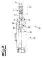
- the Fig. 7 shows a cable assembly 12 according to the invention with a protective tube 1 according to the invention, recorded in the protective tube to be tempered media line 2 and connected to a front end of the protective tube 1 and the media line 2 Quick connector 13.
- the quick connector 13 has an inner part 14 with an inner conduit 15 for the urea solution to be tempered.
- an inner shell 14 surrounding outer shell 16 is provided.
- the inner part 14 is preferably molded with plastic.
Landscapes
- Engineering & Computer Science (AREA)
- General Engineering & Computer Science (AREA)
- Mechanical Engineering (AREA)
- Rigid Pipes And Flexible Pipes (AREA)
- Protection Of Pipes Against Damage, Friction, And Corrosion (AREA)
Description
- Die Erfindung betrifft ein Schutzrohr für eine zu temperierende Medienleitung, in der ein zu temperierendes fluides Medium, insbesondere eine zu temperierende bzw. zu beheizende Harnstofflösung geführt wird, wobei das Schutzrohr bereichsweise als Wellrohr ausgebildet ist, wobei zumindest ein mittlerer Wellrohrabschnitt mit mittleren Wellenbergen und Wellentälern vorgesehen ist, wobei an zumindest einem Ende des Schutzrohres zumindest ein endseitiger Wellrohrabschnitt mit endseitigen Wellenbergen und Wellentälern angeordnet ist und wobei zwischen dem mittleren Wellrohrabschnitt und einem endseitigen Wellrohrabschnitt zumindest ein zylinderförmiger Rohrabschnitt angeordnet ist. Die Erfindung betrifft weiterhin ein Leitungsaggregat mit einem solchen Schutzrohr und einer in dem Schutzrohr aufgenommenen zu temperierenden Medienleitung sowie mit einem Verbinder bzw. Schnellverbinder.
- In Kraftfahrzeugen, insbesondere in Fahrzeugen mit Dieselmotor, ist in der Regel ein sogenanntes SCR-System mit einem SCR-Katalysator für die Abgasbehandlung vorhanden (SCR: Selective Catalytic Reduction). Für eine effektive Reduzierung der im Abgas eines Kraftfahrzeuges enthaltenen Stickoxide wird dem Abgas vor einem SCR-Katalysator eine Harnstofflösung zudosiert. Eine solche Harnstofflösung bzw. wässrige Harnstofflösung hat den Nachteil, dass Harnstoff bei Temperaturen unter -11 °C gefriert und teilweise auskristallisiert. Dadurch wird eine weitere funktionssichere Zufuhr der Harnstofflösung behindert oder vollständig blockiert und eine effektive Reduzierung der Stickoxide im Abgas beeinträchtigt bzw. verhindert. Um derartige Störungen zu vermeiden, werden die Zuführungsleitungen bzw. Rohrleitungen für die Harnstofflösung beheizt. Die Beheizung kann beispielsweise elektrisch erfolgen, und zwar insbesondere mit Heizdrähten oder Heizfolien.
- Weiterhin ist es bereits bekannt, eine solche beheizbare Medienleitung mit einem äußeren Schutzrohr zu umgeben. Das Schutzrohr umgibt die beheizbare Medienleitung in der Regel mit einem bestimmten Abstand und im Zwischenraum zwischen Schutzrohr und Medienleitung ist Luft bzw. eine Luftschicht angeordnet. Das Schutzrohr dient einerseits dem Schutz vor äußeren mechanischen Einflüssen und andererseits auch der thermischen Isolierung. Aus der Praxis ist es bekannt, ein solches Schutzrohr als Wellrohr auszubilden, und zwar normalerweise über die gesamte Länge bzw. im Wesentlichen über die gesamte Länge des Schutzrohres. Diese in Form von Wellrohren ausgeführten Schutzrohre haben jedoch den Nachteil, dass sie nicht ausreichend widerstandsfähig gegenüber einwirkenden Zugkräften und/oder Torsionskräften sind. Insoweit können bei Einwirkung derartiger Kräfte Beeinträchtigungen der Schutzfunktion bzw. Beschädigungen des Schutzrohres resultieren.
- Aus
DE 198 26 950 C1 ist ein Schutzrohr für eine Versorgungsleitung bekannt, die beispielsweise Brauchwasser- oder Heizungsrohre umfasst. Zum Schutz werden die Versorgungsleitungen durch ein zumeist als Kunststoffwellrohr ausgebildetes Schutzrohr geführt. Die Wellenberge und Wellentäler dieses Kunststoffwellrohres sind als umlaufende Wellenberge und Wellentäler ausgebildet. - Weiterhin ist ausEP 2 412 963 A1 ein Wellrohr einer Kraftstoffleitung bekannt, wobei aber der Kraftstoff durch das Wellrohr selbst fließen soll. Auch hier sind die Wellenberge und Wellentäler des Wellrohres umlaufend ausgeführt. -DE 10 2005 053390 A1 beschreibt ein Wellrohr aus thermoplastischem Material, insbesondere zur Förderung von Waschflüssigkeit in Scheibenwaschund Scheinwerferreinigungsanlagen in einem Fahrzeug. Das Wellrohr ist hier nicht als Schutzrohr, sondern ebenfalls als ein die Flüssigkeit führendes Rohr ausgebildet. - Der Erfindung liegt das technische Problem zugrunde, ein Schutzrohr der eingangs genannten Art anzugeben, bei dem die vorstehend beschriebenen Nachteile vermieden werden können. Außerdem liegt der Erfindung das technische Problem zugrunde, ein Leitungsaggregat der eingangs genannten Art mit einem erfindungsgemäßen Schutzrohr anzugeben.
- Zur Lösung dieses technischen Problems lehrt die Erfindung ein Schutzrohr der eingangs beschriebenen Art, welches dadurch gekennzeichnet ist, dass ein endseitiger Wellrohrabschnitt zumindest einen endseitigen Wellenberg aufweist, der über den gesamten Umfang des Schutzrohres umläuft und dass der end-seitige Wellrohrabschnitt zumindest einen weiteren endseitigen Wellenberg aufweist, der lediglich über einen Teil des Umfanges des Schutzrohres umläuft, und dabei über mehr als 50% des Umfanges des Schutzrohres umläuft. - Wellrohr bzw. Wellrohrabschnitt meint im Rahmen der Erfindung ein Rohr bzw. einen Rohrabschnitt mit wellenförmig wechselndem Durchmesser. In Längsrichtung des Rohres bzw. des Rohrabschnittes sind also Wellenberge und Wellentäler hintereinander angeordnet. - Zylinderförmiger Rohrabschnitt meint im Rahmen der Erfindung insbesondere einen Rohrabschnitt ohne Wellenberge und Wellentäler. Es liegt im Rahmen der Erfindung, dass ein solcher zylinderförmiger Rohrabschnitt über seine Länge den gleichen Innendurchmesser und/oder den gleichen Außendurchmesser aufweist. Zweckmäßigerweise ist ein zylinderförmiger Rohrabschnitt außen glatt bzw. unprofiliert ausgebildet.
- Es liegt im Rahmen der Erfindung, dass das erfindungsgemäße Schutzrohr eine Medienleitung für ein zu temperierendes Medium, insbesondere für eine zu beheizende Harnstofflösung umgibt. Zweckmäßigerweise ist die Medienleitung konzentrisch in dem Schutzrohr angeordnet und Medienleitung und Schutzrohr sind koaxial zueinander orientiert. Es liegt weiterhin im Rahmen der Erfindung, dass zwischen Medienleitung und Schutzrohr ein Zwischenraum vorgesehen ist, in dem Luft bzw. eine Luftschicht vorhanden ist. Nach besonders bevorzugter Ausführungsform der Erfindung wird an zumindest einem Ende des Schutzrohres bzw. an zumindest einem Ende der Medienleitung ein Verbinder bzw. Schnellverbinder angeschlossen. Der Verbinder bzw. Schnellverbinder dient zur Verbindung der Medienleitung bzw. des Schutzrohres mit einer weiteren Medienleitung bzw. mit einem weiteren Schutzrohr oder zur Verbindung mit einem Tank oder dergleichen Aggregat. Gemäß empfohlener Ausführungsform der Erfindung ist das Schutzrohr bzw. das Aggregat aus Schutzrohr und Medienleitung Bestandteil eines Kraftfahrzeuges und insbesondere Bestandteil eines SCR-Systems in einem Kraftfahrzeug.
- Zweckmäßigerweise erstreckt sich der mittlere Wellrohrabschnitt über zumindest 50 %, bevorzugt über zumindest 60 % und sehr bevorzugt über zumindest 70 % der Länge des Schutzrohres. Vorzugsweise erstreckt sich dabei der mittlere Wellrohrabschnitt unterbrechungsfrei über den betreffenden Längenabschnitt.
- Es empfiehlt sich, dass an jedem Ende des Schutzrohres bzw. im Bereich jedes Endes des Schutzrohres ein bzw. zumindest ein endseitiger Wellrohrabschnitt angeordnet ist. Erfindungsgemäß weist ein endseitiger Wellrohrabschnitt zumindest einen endseitigen Wellenberg auf, der über den gesamten Umfang des Schutzrohres umläuft. Weiterhin weist der endseitige Wellrohrabschnitt zumindest einen weiteren endseitigen Wellenberg auf, der lediglich über einen Teil des Umfanges des Schutzrohres umläuft. Vorzugsweise läuft der genannte zumindest eine Wellenberg über mehr als 50 %, bevorzugt über 50 bis 65 % des Umfanges des Schutzrohres um.
- Es hat sich als vorteilhaft erwiesen, dass ein endseitiger Wellrohrabschnitt zwei bis sechs, bevorzugt zwei bis vier endseitige Wellenberge aufweist. Empfohlenermaßen läuft dabei mindestens einer dieser endseitigen Wellenberge über den gesamten Umfang des Schutzrohres um und zumindest einer dieser endseitigen Wellenberge läuft lediglich über einen Teil des Umfanges des Schutzrohres um.
- In besonders vorteilhafter Ausgestaltung der Erfindung ist vorgesehen, dass an beiden Enden des Schutzrohres bzw. im Bereich beider Enden des Schutzrohres jeweils zumindest ein zylinderförmiger Rohrabschnitt vorgesehen ist. Es liegt im Rahmen der Erfindung, dass ein solcher zylinderförmiger Rohrabschnitt über seine Länge einen konstanten bzw. gleichbleibenden Außendurchmesser und/oder Innendurchmesser aufweist. Zweckmäßigerweise schließt ein zylinderförmiger Rohrabschnitt unmittelbar an den mittleren Wellrohrabschnitt an und vorzugsweise schließt ein endseitiger Wellrohrabschnitt unmittelbar an einen zylinderförmigen Rohrabschnitt an.
- Es empfiehlt sich, dass der zylinderförmige Rohrabschnitt eine größere Wandstärke aufweist als der mittlere Wellrohrabschnitt. Es hat sich als zweckmäßig erwiesen, dass der zylinderförmige Rohrabschnitt eine Wandstärke w1 von 0,7 bis 1,5 mm aufweist. Vorteilhafterweise beträgt die Wandstärke w2 des mittleren Wellrohrabschnittes 0,4 bis 0,7 mm. - Es hat sich bewährt, dass die Länge eines zylinderförmigen Rohrabschnittes das 0,5-fache bis 1,5-fache der Länge eines benachbarten endseitigen Wellrohrabschnittes beträgt.
- Empfohlenermaßen weist ein endseitiger Wellrohrabschnitt zumindest bereichsweise eine größere Wandstärke w3 auf als der mittlere Wellrohrabschnitt. Zweckmäßigerweise beträgt die Wandstärke w3 eines endseitigen Wellrohrabschnittes zumindest bereichsweise 0,7 bis 1,5 mm. Vorteilhafterweise entspricht die Wandstärke w3 eines endseitigen Wellrohrabschnittes zumindest bereichsweise der Wandstärke w1 bzw. in etwa der Wandstärke w1 des benachbarten zylinderförmigen Rohrabschnittes.
- Eine sehr bevorzugte Ausführungsform der Erfindung ist dadurch gekennzeichnet, dass zwischen einem Stirnende des Schutzrohres und dem diesem Stirnende zugeordneten endseitigen Wellrohrabschnitt ein zylinderförmiger Endabschnitt des Rohres angeordnet ist. Zylinderförmiger Endabschnitt meint einen Rohrabschnitt ohne Wellenberge und Wellentäler. Es liegt im Rahmen der Erfindung, dass der zylinderförmige Endabschnitt über seine Länge einen konstanten bzw. gleichbleibenden Außendurchmesser und/oder Innendurchmesser aufweist. Vorzugsweise ist die Außenseite des zylinderförmigen Endabschnittes glatt bzw. unprofiliert ausgebildet. Es empfiehlt sich, dass die Länge des zylinderförmigen Endabschnittes das 0,7-fache bis 1,5-fache, bevorzugt das 0,8-fache bis 1,3-fache der Länge des benachbarten endseitigen Wellrohrabschnittes beträgt. Zweckmäßigerweise entspricht die Wandstärke w4 eines zylinderförmigen Endabschnittes der Wandstärke w1 bzw. in etwa der Wandstärke w1 des zylinderförmigen Rohrabschnittes.
- Zur Lösung des erfindungsgemäßen technischen Problems lehrt die Erfindung weiterhin ein Leitungsaggregat mit einem erfindungsgemäßen Schutzrohr, einer in dem Schutzrohr aufgenommenen zu temperierenden Medienleitung, insbesondere für eine zu temperierende bzw. zu beheizende Harnstofflösung und mit zumindest einem an zumindest einem Stirnende des Schutzrohres bzw. der Medienleitung angeschlossenen Verbinder bzw. Schnellverbinder. Zweckmäßigerweise ist die zu temperierende bzw. zu beheizende Medienleitung konzentrisch bzw. koaxial in dem äußeren Schutzrohr angeordnet. Es liegt im Rahmen der Erfindung, dass der Verbinder bzw. Schnellverbinder für die Verbindung mit einer weiteren Medienleitung bzw. für die Verbindung mit einem diese Medienleitung umgebenden Schutzrohr vorgesehen ist oder zur Verbindung der zu temperierenden Medienleitung mit einem Tank oder dergleichen Aggregat. Der Verbinder bzw. Schnellverbinder kann dabei insbesondere für eine lineare Verbindung - beispielsweise mit einer weiteren Medienleitung - vorgesehen sein oder aber auch für eine abgewinkelte Verbindung - beispielsweise über einen Winkel von 90° mit einer weiteren Medienleitung oder mit einem Aggregat.
- Empfohlenermaßen weist der Verbinder bzw. Schnellverbinder ein Innenteil mit einem inneren Leitungskanal für das zu temperierende fluide Medium auf sowie eine das Innenteil zumindest bereichsweise umgebende äußere Ummantelung. Zweckmäßigerweise ist das Innenteil zur Verwirklichung dieser äußeren Ummantelung mit Kunststoff umgossen bzw. umspritzt. Es liegt im Rahmen der Erfindung, dass die Medienleitung an das Innenteil des Verbinders bzw. Schnellverbinders angeschlossen ist, so dass das fluide Medium bzw. die Harnstofflösung durch die Medienleitung sowie durch den inneren Leitungskanal des Innenteils des Verbinders strömen kann. Gemäß sehr bevorzugter Ausführungsform der Erfindung ist auch das dem Verbinder zugeordnete Ende des Schutzrohres mit dem Kunststoff der äußeren Ummantelung umgossen bzw. umspritzt. Vorzugsweise ist dabei der hier vorgesehene endseitige Wellrohrabschnitt zumindest über einen Teil seiner Länge, bevorzugt über seine gesamte Länge von dem Kunststoff der äußeren Ummantelung umgeben.
- Der Erfindung liegt die Erkenntnis zugrunde, dass aufgrund der erfindungsgemäßen Ausgestaltung des Schutzrohres nachteilhafte Einwirkungen von Zugkräften und/oder Torsionskräften auf das Schutzrohr vermieden werden können bzw. beachtlich reduziert werden können. Deshalb ist auch die Gefahr von Beeinträchtigungen bzw. Beschädigungen des Schutzrohres im Vergleich zu den bislang bekannten Schutzrohren wesentlich geringer. Ein erfindungsgemäßes Leitungsaggregat aus Schutzrohr, Medienleitung und Verbinder bzw. Schnellverbinder ist überraschend stabil gegenüber einwirkenden Zugkräften und/oder Torsionskräften. Hervorzuheben ist, dass das erfindungsgemäße Schutzrohr bzw. das erfindungsgemäße Leitungsaggregat mit geringem Aufwand und somit auch mit geringen Kosten realisiert werden kann.
- Nachfolgend wird die Erfindung anhand einer lediglich ein Ausführungsbeispiel darstellenden Zeichnung näher erläutert. Es zeigen in schematischer Darstellung:
- Fig. 1
- eine perspektivische Ansicht eines Endes eines erfindungsgemäßen Schutzrohres,
- Fig. 2
- eine Seitenansicht des Gegenstandes nach
Fig. 1 im Schnitt, - Fig. 3
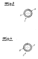
- einen Schnitt A-A durch den Gegenstand gemäß
Fig. 2 , - Fig. 4
- einen Schnitt B-B durch den Gegenstand nach
Fig. 2 , - Fig. 5
- den Gegenstand gemäß
Fig. 1 in einer weiteren Ausführungsform, - Fig. 6
- einen Schnitt C-C durch den Gegenstand nach
Fig. 5 und - Fig. 7
- eine Seitenansicht eines erfindungsgemäßen Leitungsaggregates.
- Die Figuren zeigen ein erfindungsgemäßes Schutzrohr 1 für eine zu beheizende Medienleitung 2, wobei eine zu beheizende wässrige Harnstofflösung durch diese Medienleitung 2 geführt wird. Die Medienleitung 2 kann beispielsweise mit einem nicht dargestellten Heizdraht beheizt werden. Erfindungsgemäß ist das Schutzrohr 1 lediglich bereichsweise als Wellrohr ausgebildet und das Schutzrohr 1 weist im Ausführungsbeispiel einen mittleren Wellrohrabschnitt 3 mit mittleren Wellenbergen 4 und mittleren Wellentälern 5 auf. Der mittlere Wellrohrabschnitt 3 erstreckt sich vorzugsweise über mehr als 70 % der Länge des Schutzrohres 1. In den Figuren ist jeweils nur ein Ende des Schutzrohres 1 dargestellt. Es liegt im Rahmen der Erfindung, dass das zweite Ende des Schutzrohres 1 analog ausgebildet ist.
- Im Bereich des Endes des Schutzrohres 1 ist vorzugsweise jeweils ein endseitiger Wellrohrabschnitt 6 mit endseitigen Wellenbergen 7 und endseitigen Wellentälern 8 angeordnet. Die mittleren Wellenberge 4 und die mittleren Wellentäler 5 des mittleren Wellrohrabschnittes 3 laufen zweckmäßigerweise und im Ausführungsbeispiel allesamt über den gesamten Umfang des Schutzrohres 1 um. Im Ausführungsbeispiel nach
Fig. 1 läuft lediglich ein endseitiger Wellenberg 7 um den gesamten Umfang des Schutzrohres 1 um. Dagegen laufen zwei endseitige Wellenberge 7 lediglich über einen Teil des Umfanges des Schutzrohres 1 um. Diese endseitigen Wellenberge 7 des endseitigen Wellrohrabschnittes 6 laufen im Ausführungsbeispiel aber um mehr als 50 % des Umfanges des Schutzrohres 1 um. Dazu wird insbesondere auf dieFig. 3 und 4 verwiesen. Im Ausführungsbeispiel nachFig. 5 laufen zwei endseitige Wellenberge 7 des endseitigen Wellrohrabschnittes 6 über den gesamten Umfang des Schutzrohres 1 um. Dagegen läuft nur ein endseitiger Wellenberg 7 des endseitigen Wellrohrabschnittes 6 über lediglich einen Teil des Umfanges des Schutzrohres 1 um, und zwar über mehr als 50 % des Umfanges des Schutzrohres 1 (sieheFig. 6 ). - Im Ausführungsbeispiel nach den Figuren ist zwischen dem mittleren Wellrohrabschnitt 3 und dem endseitigen Wellrohrabschnitt 6 ein zylinderförmiger Rohrabschnitt 9 angeordnet. Im Unterschied zu den Wellrohrabschnitten 3, 6 weist dieser zylinderförmiger Rohrabschnitt 9 im Ausführungsbeispiel über seine Länge einen konstanten Außendurchmesser und einen konstanten Innendurchmesser auf. In der
Fig. 2 ist erkennbar, dass der zylinderförmige Rohrabschnitt 9 eine Wandstärke w1 aufweist, die größer ist als die Wandstärke w2 des mittleren Wellrohrabschnittes 3. Im Ausführungsbeispiel nach den Figuren ist ein endseitiger Wellrohrabschnitt 6 etwas länger als der daran anschließende zylinderförmige Rohrabschnitt 9. Zweckmäßigerweise und im Ausführungsbeispiel entspricht die Wandstärke w3 eines endseitigen Wellrohrabschnittes 6 zumindest bereichsweise - hier im Bereich der endseitigen Wellentäler 8 - der Wandstärke w1 des zylinderförmigen Rohrabschnittes 9. - Vorzugsweise und im Ausführungsbeispiel ist zwischen einem Stirnende 10 des Schutzrohres 1 und dem diesem Stirnende zugeordneten endseitigen Wellrohrabschnitt 6 ein zylinderförmiger Endabschnitt 11 des Rohres 1 angeordnet. Die Länge des zylinderförmigen Endabschnittes 11 entspricht im Ausführungsbeispiel nach den Figuren in etwa der Länge des daran anschließenden endseitigen Wellrohrabschnittes 6. Im Ausführungsbeispiel entspricht die Wandstärke w4 eines zylinderförmigen Endabschnittes 11 der Wandstärke w1 eines zylinderförmigen Rohrabschnittes 9.
- Die
Fig. 7 zeigt ein erfindungsgemäßes Leitungsaggregat 12 mit einem erfindungsgemäßen Schutzrohr 1, einer in dem Schutzrohr aufgenommenen zu temperierenden Medienleitung 2 und mit einem an einem Stirnende des Schutzrohres 1 bzw. der Medienleitung 2 angeschlossenen Schnellverbinder 13. Der Schnellverbinder 13 weist ein Innenteil 14 mit einem inneren Leitungskanal 15 für die zu temperierende Harnstofflösung auf. Außerdem ist eine das Innenteil 14 umgebende äußere Ummantelung 16 vorgesehen. Zur Verwirklichung dieser äußeren Ummantelung 16 wird das Innenteil 14 vorzugsweise mit Kunststoff umgossen. Nach sehr bevorzugter Ausführungsform der Erfindung wird auch das an den Schnellverbinder 13 angeschlossene Ende des Schutzrohres 1 mit dem Kunststoff umgossen, so dass der hier angeordnete endseitige Wellrohrabschnitt 6 von dem Kunststoff umgeben ist.
Claims (11)
- Schutzrohr (1) für eine zu temperierende Medienleitung (2), wobei das Schutzrohr (1) bereichsweise als Wellrohr ausgebildet ist, wobei zumindest ein mittlerer Wellrohrabschnitt (3) mit mittleren Wellenbergen (4) und Wellentälern (5) vorgesehen ist, wobei an zumindest einem Ende des Schutzrohres (1) zumindest ein endseitiger Wellrohrabschnitt (6) mit endseitigen Wellenbergen (7) und Wellentälern (8) angeordnet ist und wobei zwischen dem mittleren Wellrohrabschnitt (3) und einem endseitigen Wellrohrabschnitt (6) zumindest ein zylinderförmiger Rohrabschnitt (9) angeordnet ist, dadurch gekenn- zeichnet, dass ein endseitiger Wellrohrabschnitt (6) zumindest einen endseitigen Wellenberg (7) aufweist, der über den gesamten Umfang des Schutzrohres, (1) umläuft und dass der endseitige Wellrohrabschnitt (6) zumindest einen weiteren endseitigen Wellenberg aufweist, der lediglich über einen Teil des Umfanges des Schutzrohres (1) umläuft und dabei über mehr als 50% des Umfanges des Schutzrohres (1) umläuft.
- Schutzrohr nach Anspruch 1, dadurch gekennzeichnet, dass sich der mittlere Wellrohrabschnitt (3) über zumindest 50 %, bevorzugt über zumindest 70 % der Länge des Schutzrohres (1) erstreckt.
- Schutzrohr nach einem der Ansprüche 1 oder 2, dadurch gekennzeichnet, dass ein endseitiger Wellrohrabschnitt (6) zwei bis sechs, vorzugsweise zwei bis vier endseitige Wellenberge (7) aufweist.
- Schutzrohr nach einem der Ansprüche 1 bis 3, dadurch gekennzeichnet, dass der zylinderförmige Rohrabschnitt (9) über seine Länge einen konstanten Außendurchmesser und/ oder Innendurchmesser aufweist.
- Schutzrohr nach einem der Ansprüche 1 bis 4, dadurch gekennzeichnet, dass der zylinderförmige Rohrabschnitt (9) eine größere Wandstärke (w1) aufweist als der mittlere Wellrohrabschnitt (3).
- Schutzrohr nach einem der Ansprüche 1 bis 5, dadurch gekennzeichnet, dass die Länge eines zylinderförmigen Rohrabschnittes (9) das 0,5-fache bis 1,5-fache der Länge eines endseitigen Wellrohrabschnittes (6) beträgt.
- Schutzrohr nach einem der Ansprüche 1 bis 6, dadurch gekennzeichnet, dass zwischen einem Stirnende (10) des Schutzrohres (1) und dem diesem Stirnende zugeordneten endseitigen Wellrohrabschnitt (6) ein zylinderförmiger Endabschnitt (11) des Rohres (1) angeordnet ist.
- Schutzrohr nach einem der Ansprüche 1 bis 7, dadurch gekennzeichnet, dass die Länge des zylinderförmigen Endabschnittes (11) das 0,7-fache bis 1,5-fache der Länge des benachbarten endseitigen Wellrohrabschnittes (6) beträgt.
- Leitungsaggregat (12) mit einem Schutzrohr (1) nach einem der Ansprüche 1 bis 8, einer in dem Schutzrohr (1) aufgenommenen zu temperierenden Medienleitung (2), insbesondere für eine zu temperierende Harnstofflösung und mit zumindest einem an zumindest einem Stirnende (10) des Schutzrohres (1) bzw. der Medienleitung (2) angeschlossenen Verbinder bzw. Schnellverbinder (13).
- Leitungsaggregat nach Anspruch 9, dadurch gekennzeichnet, dass der Verbinder bzw. Schnellverbinder (13) ein Innenteil (14) mit einem Leitungskanal (15) für das zu temperierende fluide Medium sowie eine das Innenteil (14) zumindest bereichsweise umgebende äußere Ummantelung (16) aufweist und wobei das Innenteil (14) zur Realisierung der äußeren Ummantelung (16) mit Kunststoff umgossen bzw. umspritzt ist.
- Leitungsaggregat nach einem der Ansprüche 9 oder 10, dadurch gekennzeichnet, dass das den Verbinder bzw. Schnellverbinder (13) zugeordnete Ende des Schutzrohres (1) mit dem Kunststoff umgossen bzw. umspritzt ist, so dass der hier vorgesehene endseitige Wellrohrabschnitt (6) zumindest über einen Teil seiner Länge von dem Kunststoff umgeben ist.
Priority Applications (1)
| Application Number | Priority Date | Filing Date | Title |
|---|---|---|---|
| PL13165619T PL2662606T3 (pl) | 2012-05-07 | 2013-04-26 | Rura ochronna dla przewodu temperowanego czynnika i zespół przewodzący |
Applications Claiming Priority (1)
| Application Number | Priority Date | Filing Date | Title |
|---|---|---|---|
| DE202012101676U DE202012101676U1 (de) | 2012-05-07 | 2012-05-07 | Schutzrohr für eine zu temperierende Medienleitung und Leitungsaggregat |
Publications (2)
| Publication Number | Publication Date |
|---|---|
| EP2662606A1 EP2662606A1 (de) | 2013-11-13 |
| EP2662606B1 true EP2662606B1 (de) | 2015-09-23 |
Family
ID=46510082
Family Applications (1)
| Application Number | Title | Priority Date | Filing Date |
|---|---|---|---|
| EP13165619.1A Active EP2662606B1 (de) | 2012-05-07 | 2013-04-26 | Schutzrohr für eine zu temperierende Medienleitung und Leitungsaggregat |
Country Status (5)
| Country | Link |
|---|---|
| EP (1) | EP2662606B1 (de) |
| DE (1) | DE202012101676U1 (de) |
| ES (1) | ES2557189T3 (de) |
| HU (1) | HUE026966T2 (de) |
| PL (1) | PL2662606T3 (de) |
Families Citing this family (3)
| Publication number | Priority date | Publication date | Assignee | Title |
|---|---|---|---|---|
| DE102014111458A1 (de) * | 2014-08-12 | 2016-02-18 | Norma Germany Gmbh | Fluidleitung |
| KR102709712B1 (ko) * | 2018-03-29 | 2024-09-24 | 듀폰 폴리머스, 인크. | 유체 덕트 |
| DE102019117980A1 (de) * | 2019-07-03 | 2021-01-07 | Walter H. Frieß | Rohr |
Citations (2)
| Publication number | Priority date | Publication date | Assignee | Title |
|---|---|---|---|---|
| US6447709B1 (en) * | 1999-10-25 | 2002-09-10 | Honda Giken Kogyo Kabushiki Kaisha | Process for producing resinous hose |
| US20040239109A1 (en) * | 2003-05-29 | 2004-12-02 | Dormont Manufacturing Company | Fluid line connector with intermediate smooth surface |
Family Cites Families (5)
| Publication number | Priority date | Publication date | Assignee | Title |
|---|---|---|---|---|
| IT229892Y1 (it) * | 1993-05-06 | 1999-02-05 | Lombarde Ind Plastiche | Elemento di raccordo sostanzialmente flessibile e deformabile per il collegamento di tubazioni in genere |
| DE19826950C1 (de) * | 1998-06-17 | 1999-09-23 | Hewing Gmbh | Schutzrohr für eine Versorgungsleitung |
| DE102005053390A1 (de) * | 2005-11-09 | 2007-05-10 | Volkswagen Ag | Wellrohr aus thermoplastischem Material |
| ITTO20050876A1 (it) * | 2005-12-15 | 2007-06-16 | Eltek Spa | Dispositivo di sicurezza antiallagamento per elettrodomestici, in particolare macchine di lavaggio |
| DE102010032220A1 (de) * | 2010-07-26 | 2012-01-26 | Continental Automotive Gmbh | Wellrohr einer Kraftstoffleitung |
-
2012
- 2012-05-07 DE DE202012101676U patent/DE202012101676U1/de not_active Expired - Lifetime
-
2013
- 2013-04-26 ES ES13165619.1T patent/ES2557189T3/es active Active
- 2013-04-26 HU HUE13165619A patent/HUE026966T2/en unknown
- 2013-04-26 EP EP13165619.1A patent/EP2662606B1/de active Active
- 2013-04-26 PL PL13165619T patent/PL2662606T3/pl unknown
Patent Citations (2)
| Publication number | Priority date | Publication date | Assignee | Title |
|---|---|---|---|---|
| US6447709B1 (en) * | 1999-10-25 | 2002-09-10 | Honda Giken Kogyo Kabushiki Kaisha | Process for producing resinous hose |
| US20040239109A1 (en) * | 2003-05-29 | 2004-12-02 | Dormont Manufacturing Company | Fluid line connector with intermediate smooth surface |
Also Published As
| Publication number | Publication date |
|---|---|
| EP2662606A1 (de) | 2013-11-13 |
| HUE026966T2 (en) | 2016-07-28 |
| PL2662606T3 (pl) | 2016-04-29 |
| DE202012101676U1 (de) | 2012-05-21 |
| ES2557189T3 (es) | 2016-01-22 |
Similar Documents
| Publication | Publication Date | Title |
|---|---|---|
| EP2167860B1 (de) | Anschlussvorrichtung für medienführende, elektrisch beheizbare schläuche | |
| EP2653770B1 (de) | Verbinder, insbesondere Schnellverbinder | |
| EP2278133B1 (de) | Misch- und/oder Verdampfungseinrichtung | |
| EP2653765B1 (de) | Rohrleitung für ein zu temperierendes fluides Medium | |
| EP2802754B1 (de) | Motorblock-anordnung mit einem abgassystem | |
| DE102008018461B4 (de) | Mischvorrichtung für eine Abgasnachbehandlungsanlage | |
| EP2126294B1 (de) | Abgasnachbehandlungseinrichtung eines kraftfahrzeugs | |
| EP3276243B2 (de) | Kraftfahrzeug-fluidleitung | |
| EP3495707B1 (de) | Fluidleitung, verwendung einer solchen zum transport einer harnstofflösung und verfahren zur vermeidung des risikos einer beschädigung einer einspritzanordnung eines dieselmotors durch einfrierende harnstofflösung | |
| EP2415986B1 (de) | Vorrichtung mit einer Reduktionsmittelleitung und einem Windschutzelement | |
| EP2027372A1 (de) | Nebenstromfilter mit verbessertem filterwirkungsgrad | |
| EP2662606A1 (de) | Schutzrohr für eine zu temperierende Medienleitung und Leitungsaggregat | |
| EP2666985B1 (de) | Beheizbare Medienleitung | |
| WO2011138191A1 (de) | Behälter mit einer entnahmeleitung für eine betriebsflüssigkeit eines kraftfahrzeugs | |
| EP2748024B1 (de) | Tankanordnung sowie abgasreinigungseinrichtung | |
| EP2667077A1 (de) | Hitzeschutzmantel für einen Verbinder, Verbinder und Medienleitung | |
| EP3327261B1 (de) | Abgasbehandlungsanordnung | |
| DE202015100469U1 (de) | Rohrleitungsaggregat und Verbinderaggregat | |
| EP3133329B1 (de) | Beheizbare kraftfahrzeugrohrleitung und verfahren zur herstellung einer beheizbaren kraftfahrzeugrohrleitung | |
| DE102019133140A1 (de) | "Leitungsverbinder" | |
| DE102016111549A1 (de) | Leitungselement für eine Abgasleitung | |
| DE102018107004B4 (de) | Beheizte Medienleitung mit Fixierteil | |
| EP2667075A2 (de) | Aggregat aus einem Verbinder und einer Medienleitung | |
| DE102013215494A1 (de) | Entkoppelelement für eine Abgasanlage | |
| DE102012208929A1 (de) | Abgasnachbehandlungseinrichtung |
Legal Events
| Date | Code | Title | Description |
|---|---|---|---|
| PUAI | Public reference made under article 153(3) epc to a published international application that has entered the european phase |
Free format text: ORIGINAL CODE: 0009012 |
|
| AK | Designated contracting states |
Kind code of ref document: A1 Designated state(s): AL AT BE BG CH CY CZ DE DK EE ES FI FR GB GR HR HU IE IS IT LI LT LU LV MC MK MT NL NO PL PT RO RS SE SI SK SM TR |
|
| AX | Request for extension of the european patent |
Extension state: BA ME |
|
| 17P | Request for examination filed |
Effective date: 20131213 |
|
| RBV | Designated contracting states (corrected) |
Designated state(s): AL AT BE BG CH CY CZ DE DK EE ES FI FR GB GR HR HU IE IS IT LI LT LU LV MC MK MT NL NO PL PT RO RS SE SI SK SM TR |
|
| 17Q | First examination report despatched |
Effective date: 20141027 |
|
| GRAP | Despatch of communication of intention to grant a patent |
Free format text: ORIGINAL CODE: EPIDOSNIGR1 |
|
| INTG | Intention to grant announced |
Effective date: 20150417 |
|
| GRAS | Grant fee paid |
Free format text: ORIGINAL CODE: EPIDOSNIGR3 |
|
| GRAA | (expected) grant |
Free format text: ORIGINAL CODE: 0009210 |
|
| AK | Designated contracting states |
Kind code of ref document: B1 Designated state(s): AL AT BE BG CH CY CZ DE DK EE ES FI FR GB GR HR HU IE IS IT LI LT LU LV MC MK MT NL NO PL PT RO RS SE SI SK SM TR |
|
| REG | Reference to a national code |
Ref country code: GB Ref legal event code: FG4D Free format text: NOT ENGLISH |
|
| REG | Reference to a national code |
Ref country code: CH Ref legal event code: EP |
|
| REG | Reference to a national code |
Ref country code: AT Ref legal event code: REF Ref document number: 751446 Country of ref document: AT Kind code of ref document: T Effective date: 20151015 |
|
| REG | Reference to a national code |
Ref country code: IE Ref legal event code: FG4D Free format text: LANGUAGE OF EP DOCUMENT: GERMAN |
|
| REG | Reference to a national code |
Ref country code: DE Ref legal event code: R096 Ref document number: 502013001224 Country of ref document: DE |
|
| REG | Reference to a national code |
Ref country code: ES Ref legal event code: FG2A Ref document number: 2557189 Country of ref document: ES Kind code of ref document: T3 Effective date: 20160122 |
|
| REG | Reference to a national code |
Ref country code: SE Ref legal event code: TRGR |
|
| REG | Reference to a national code |
Ref country code: NL Ref legal event code: MP Effective date: 20150923 |
|
| PG25 | Lapsed in a contracting state [announced via postgrant information from national office to epo] |
Ref country code: NO Free format text: LAPSE BECAUSE OF FAILURE TO SUBMIT A TRANSLATION OF THE DESCRIPTION OR TO PAY THE FEE WITHIN THE PRESCRIBED TIME-LIMIT Effective date: 20151223 Ref country code: LT Free format text: LAPSE BECAUSE OF FAILURE TO SUBMIT A TRANSLATION OF THE DESCRIPTION OR TO PAY THE FEE WITHIN THE PRESCRIBED TIME-LIMIT Effective date: 20150923 Ref country code: GR Free format text: LAPSE BECAUSE OF FAILURE TO SUBMIT A TRANSLATION OF THE DESCRIPTION OR TO PAY THE FEE WITHIN THE PRESCRIBED TIME-LIMIT Effective date: 20151224 Ref country code: FI Free format text: LAPSE BECAUSE OF FAILURE TO SUBMIT A TRANSLATION OF THE DESCRIPTION OR TO PAY THE FEE WITHIN THE PRESCRIBED TIME-LIMIT Effective date: 20150923 Ref country code: LV Free format text: LAPSE BECAUSE OF FAILURE TO SUBMIT A TRANSLATION OF THE DESCRIPTION OR TO PAY THE FEE WITHIN THE PRESCRIBED TIME-LIMIT Effective date: 20150923 |
|
| REG | Reference to a national code |
Ref country code: LT Ref legal event code: MG4D |
|
| PG25 | Lapsed in a contracting state [announced via postgrant information from national office to epo] |
Ref country code: RS Free format text: LAPSE BECAUSE OF FAILURE TO SUBMIT A TRANSLATION OF THE DESCRIPTION OR TO PAY THE FEE WITHIN THE PRESCRIBED TIME-LIMIT Effective date: 20150923 Ref country code: HR Free format text: LAPSE BECAUSE OF FAILURE TO SUBMIT A TRANSLATION OF THE DESCRIPTION OR TO PAY THE FEE WITHIN THE PRESCRIBED TIME-LIMIT Effective date: 20150923 |
|
| PG25 | Lapsed in a contracting state [announced via postgrant information from national office to epo] |
Ref country code: NL Free format text: LAPSE BECAUSE OF FAILURE TO SUBMIT A TRANSLATION OF THE DESCRIPTION OR TO PAY THE FEE WITHIN THE PRESCRIBED TIME-LIMIT Effective date: 20150923 |
|
| REG | Reference to a national code |
Ref country code: FR Ref legal event code: PLFP Year of fee payment: 4 |
|
| PG25 | Lapsed in a contracting state [announced via postgrant information from national office to epo] |
Ref country code: SK Free format text: LAPSE BECAUSE OF FAILURE TO SUBMIT A TRANSLATION OF THE DESCRIPTION OR TO PAY THE FEE WITHIN THE PRESCRIBED TIME-LIMIT Effective date: 20150923 Ref country code: IS Free format text: LAPSE BECAUSE OF FAILURE TO SUBMIT A TRANSLATION OF THE DESCRIPTION OR TO PAY THE FEE WITHIN THE PRESCRIBED TIME-LIMIT Effective date: 20160123 Ref country code: EE Free format text: LAPSE BECAUSE OF FAILURE TO SUBMIT A TRANSLATION OF THE DESCRIPTION OR TO PAY THE FEE WITHIN THE PRESCRIBED TIME-LIMIT Effective date: 20150923 |
|
| PG25 | Lapsed in a contracting state [announced via postgrant information from national office to epo] |
Ref country code: RO Free format text: LAPSE BECAUSE OF FAILURE TO SUBMIT A TRANSLATION OF THE DESCRIPTION OR TO PAY THE FEE WITHIN THE PRESCRIBED TIME-LIMIT Effective date: 20150923 Ref country code: PT Free format text: LAPSE BECAUSE OF FAILURE TO SUBMIT A TRANSLATION OF THE DESCRIPTION OR TO PAY THE FEE WITHIN THE PRESCRIBED TIME-LIMIT Effective date: 20160125 |
|
| REG | Reference to a national code |
Ref country code: DE Ref legal event code: R097 Ref document number: 502013001224 Country of ref document: DE |
|
| REG | Reference to a national code |
Ref country code: HU Ref legal event code: AG4A Ref document number: E026966 Country of ref document: HU |
|
| PLBE | No opposition filed within time limit |
Free format text: ORIGINAL CODE: 0009261 |
|
| STAA | Information on the status of an ep patent application or granted ep patent |
Free format text: STATUS: NO OPPOSITION FILED WITHIN TIME LIMIT |
|
| 26N | No opposition filed |
Effective date: 20160624 |
|
| PG25 | Lapsed in a contracting state [announced via postgrant information from national office to epo] |
Ref country code: BE Free format text: LAPSE BECAUSE OF NON-PAYMENT OF DUE FEES Effective date: 20160430 Ref country code: DK Free format text: LAPSE BECAUSE OF FAILURE TO SUBMIT A TRANSLATION OF THE DESCRIPTION OR TO PAY THE FEE WITHIN THE PRESCRIBED TIME-LIMIT Effective date: 20150923 |
|
| PG25 | Lapsed in a contracting state [announced via postgrant information from national office to epo] |
Ref country code: SI Free format text: LAPSE BECAUSE OF FAILURE TO SUBMIT A TRANSLATION OF THE DESCRIPTION OR TO PAY THE FEE WITHIN THE PRESCRIBED TIME-LIMIT Effective date: 20150923 |
|
| REG | Reference to a national code |
Ref country code: CH Ref legal event code: PL |
|
| PG25 | Lapsed in a contracting state [announced via postgrant information from national office to epo] |
Ref country code: LU Free format text: LAPSE BECAUSE OF FAILURE TO SUBMIT A TRANSLATION OF THE DESCRIPTION OR TO PAY THE FEE WITHIN THE PRESCRIBED TIME-LIMIT Effective date: 20160426 |
|
| REG | Reference to a national code |
Ref country code: IE Ref legal event code: MM4A |
|
| PG25 | Lapsed in a contracting state [announced via postgrant information from national office to epo] |
Ref country code: LI Free format text: LAPSE BECAUSE OF NON-PAYMENT OF DUE FEES Effective date: 20160430 Ref country code: CH Free format text: LAPSE BECAUSE OF NON-PAYMENT OF DUE FEES Effective date: 20160430 |
|
| REG | Reference to a national code |
Ref country code: FR Ref legal event code: PLFP Year of fee payment: 5 |
|
| PG25 | Lapsed in a contracting state [announced via postgrant information from national office to epo] |
Ref country code: IE Free format text: LAPSE BECAUSE OF NON-PAYMENT OF DUE FEES Effective date: 20160426 |
|
| GBPC | Gb: european patent ceased through non-payment of renewal fee |
Effective date: 20170426 |
|
| PG25 | Lapsed in a contracting state [announced via postgrant information from national office to epo] |
Ref country code: GB Free format text: LAPSE BECAUSE OF NON-PAYMENT OF DUE FEES Effective date: 20170426 |
|
| REG | Reference to a national code |
Ref country code: FR Ref legal event code: PLFP Year of fee payment: 6 |
|
| PG25 | Lapsed in a contracting state [announced via postgrant information from national office to epo] |
Ref country code: SM Free format text: LAPSE BECAUSE OF FAILURE TO SUBMIT A TRANSLATION OF THE DESCRIPTION OR TO PAY THE FEE WITHIN THE PRESCRIBED TIME-LIMIT Effective date: 20150923 Ref country code: CY Free format text: LAPSE BECAUSE OF FAILURE TO SUBMIT A TRANSLATION OF THE DESCRIPTION OR TO PAY THE FEE WITHIN THE PRESCRIBED TIME-LIMIT Effective date: 20150923 |
|
| PG25 | Lapsed in a contracting state [announced via postgrant information from national office to epo] |
Ref country code: MC Free format text: LAPSE BECAUSE OF FAILURE TO SUBMIT A TRANSLATION OF THE DESCRIPTION OR TO PAY THE FEE WITHIN THE PRESCRIBED TIME-LIMIT Effective date: 20150923 Ref country code: MT Free format text: LAPSE BECAUSE OF FAILURE TO SUBMIT A TRANSLATION OF THE DESCRIPTION OR TO PAY THE FEE WITHIN THE PRESCRIBED TIME-LIMIT Effective date: 20150923 Ref country code: MK Free format text: LAPSE BECAUSE OF FAILURE TO SUBMIT A TRANSLATION OF THE DESCRIPTION OR TO PAY THE FEE WITHIN THE PRESCRIBED TIME-LIMIT Effective date: 20150923 Ref country code: TR Free format text: LAPSE BECAUSE OF FAILURE TO SUBMIT A TRANSLATION OF THE DESCRIPTION OR TO PAY THE FEE WITHIN THE PRESCRIBED TIME-LIMIT Effective date: 20150923 |
|
| PG25 | Lapsed in a contracting state [announced via postgrant information from national office to epo] |
Ref country code: BG Free format text: LAPSE BECAUSE OF FAILURE TO SUBMIT A TRANSLATION OF THE DESCRIPTION OR TO PAY THE FEE WITHIN THE PRESCRIBED TIME-LIMIT Effective date: 20150923 |
|
| PG25 | Lapsed in a contracting state [announced via postgrant information from national office to epo] |
Ref country code: AL Free format text: LAPSE BECAUSE OF FAILURE TO SUBMIT A TRANSLATION OF THE DESCRIPTION OR TO PAY THE FEE WITHIN THE PRESCRIBED TIME-LIMIT Effective date: 20150923 |
|
| REG | Reference to a national code |
Ref country code: AT Ref legal event code: MM01 Ref document number: 751446 Country of ref document: AT Kind code of ref document: T Effective date: 20180426 |
|
| PG25 | Lapsed in a contracting state [announced via postgrant information from national office to epo] |
Ref country code: AT Free format text: LAPSE BECAUSE OF NON-PAYMENT OF DUE FEES Effective date: 20180426 |
|
| PGFP | Annual fee paid to national office [announced via postgrant information from national office to epo] |
Ref country code: CZ Payment date: 20200422 Year of fee payment: 8 Ref country code: ES Payment date: 20200516 Year of fee payment: 8 |
|
| PGFP | Annual fee paid to national office [announced via postgrant information from national office to epo] |
Ref country code: IT Payment date: 20200423 Year of fee payment: 8 Ref country code: PL Payment date: 20200420 Year of fee payment: 8 Ref country code: SE Payment date: 20200429 Year of fee payment: 8 Ref country code: HU Payment date: 20200415 Year of fee payment: 8 |
|
| REG | Reference to a national code |
Ref country code: SE Ref legal event code: EUG |
|
| PG25 | Lapsed in a contracting state [announced via postgrant information from national office to epo] |
Ref country code: HU Free format text: LAPSE BECAUSE OF NON-PAYMENT OF DUE FEES Effective date: 20210427 Ref country code: CZ Free format text: LAPSE BECAUSE OF NON-PAYMENT OF DUE FEES Effective date: 20210426 Ref country code: SE Free format text: LAPSE BECAUSE OF NON-PAYMENT OF DUE FEES Effective date: 20210427 |
|
| REG | Reference to a national code |
Ref country code: ES Ref legal event code: FD2A Effective date: 20220801 |
|
| PG25 | Lapsed in a contracting state [announced via postgrant information from national office to epo] |
Ref country code: ES Free format text: LAPSE BECAUSE OF NON-PAYMENT OF DUE FEES Effective date: 20210427 |
|
| PG25 | Lapsed in a contracting state [announced via postgrant information from national office to epo] |
Ref country code: PL Free format text: LAPSE BECAUSE OF NON-PAYMENT OF DUE FEES Effective date: 20210426 |
|
| PG25 | Lapsed in a contracting state [announced via postgrant information from national office to epo] |
Ref country code: IT Free format text: LAPSE BECAUSE OF NON-PAYMENT OF DUE FEES Effective date: 20200426 |
|
| P01 | Opt-out of the competence of the unified patent court (upc) registered |
Effective date: 20230524 |
|
| PGFP | Annual fee paid to national office [announced via postgrant information from national office to epo] |
Ref country code: DE Payment date: 20250417 Year of fee payment: 13 |
|
| PGFP | Annual fee paid to national office [announced via postgrant information from national office to epo] |
Ref country code: FR Payment date: 20250422 Year of fee payment: 13 |
|
| PG25 | Lapsed in a contracting state [announced via postgrant information from national office to epo] |
Ref country code: IT Free format text: LAPSE BECAUSE OF NON-PAYMENT OF DUE FEES Effective date: 20210426 |