EP2662555A1 - Method for monitoring an injection valve - Google Patents
Method for monitoring an injection valve Download PDFInfo
- Publication number
- EP2662555A1 EP2662555A1 EP20120167414 EP12167414A EP2662555A1 EP 2662555 A1 EP2662555 A1 EP 2662555A1 EP 20120167414 EP20120167414 EP 20120167414 EP 12167414 A EP12167414 A EP 12167414A EP 2662555 A1 EP2662555 A1 EP 2662555A1
- Authority
- EP
- European Patent Office
- Prior art keywords
- time
- gradient
- starting
- current
- gradient alteration
- Prior art date
- Legal status (The legal status is an assumption and is not a legal conclusion. Google has not performed a legal analysis and makes no representation as to the accuracy of the status listed.)
- Withdrawn
Links
Images


Classifications
-
- F—MECHANICAL ENGINEERING; LIGHTING; HEATING; WEAPONS; BLASTING
- F02—COMBUSTION ENGINES; HOT-GAS OR COMBUSTION-PRODUCT ENGINE PLANTS
- F02M—SUPPLYING COMBUSTION ENGINES IN GENERAL WITH COMBUSTIBLE MIXTURES OR CONSTITUENTS THEREOF
- F02M51/00—Fuel-injection apparatus characterised by being operated electrically
- F02M51/06—Injectors peculiar thereto with means directly operating the valve needle
- F02M51/061—Injectors peculiar thereto with means directly operating the valve needle using electromagnetic operating means
-
- F—MECHANICAL ENGINEERING; LIGHTING; HEATING; WEAPONS; BLASTING
- F02—COMBUSTION ENGINES; HOT-GAS OR COMBUSTION-PRODUCT ENGINE PLANTS
- F02D—CONTROLLING COMBUSTION ENGINES
- F02D41/00—Electrical control of supply of combustible mixture or its constituents
- F02D41/22—Safety or indicating devices for abnormal conditions
- F02D41/221—Safety or indicating devices for abnormal conditions relating to the failure of actuators or electrically driven elements
-
- F—MECHANICAL ENGINEERING; LIGHTING; HEATING; WEAPONS; BLASTING
- F02—COMBUSTION ENGINES; HOT-GAS OR COMBUSTION-PRODUCT ENGINE PLANTS
- F02D—CONTROLLING COMBUSTION ENGINES
- F02D41/00—Electrical control of supply of combustible mixture or its constituents
- F02D41/24—Electrical control of supply of combustible mixture or its constituents characterised by the use of digital means
- F02D41/2406—Electrical control of supply of combustible mixture or its constituents characterised by the use of digital means using essentially read only memories
- F02D41/2425—Particular ways of programming the data
- F02D41/2429—Methods of calibrating or learning
- F02D41/2451—Methods of calibrating or learning characterised by what is learned or calibrated
- F02D41/2464—Characteristics of actuators
- F02D41/2467—Characteristics of actuators for injectors
-
- F—MECHANICAL ENGINEERING; LIGHTING; HEATING; WEAPONS; BLASTING
- F02—COMBUSTION ENGINES; HOT-GAS OR COMBUSTION-PRODUCT ENGINE PLANTS
- F02M—SUPPLYING COMBUSTION ENGINES IN GENERAL WITH COMBUSTIBLE MIXTURES OR CONSTITUENTS THEREOF
- F02M57/00—Fuel-injectors combined or associated with other devices
- F02M57/005—Fuel-injectors combined or associated with other devices the devices being sensors
-
- F—MECHANICAL ENGINEERING; LIGHTING; HEATING; WEAPONS; BLASTING
- F02—COMBUSTION ENGINES; HOT-GAS OR COMBUSTION-PRODUCT ENGINE PLANTS
- F02D—CONTROLLING COMBUSTION ENGINES
- F02D41/00—Electrical control of supply of combustible mixture or its constituents
- F02D41/20—Output circuits, e.g. for controlling currents in command coils
- F02D2041/202—Output circuits, e.g. for controlling currents in command coils characterised by the control of the circuit
- F02D2041/2034—Control of the current gradient
-
- F—MECHANICAL ENGINEERING; LIGHTING; HEATING; WEAPONS; BLASTING
- F02—COMBUSTION ENGINES; HOT-GAS OR COMBUSTION-PRODUCT ENGINE PLANTS
- F02D—CONTROLLING COMBUSTION ENGINES
- F02D41/00—Electrical control of supply of combustible mixture or its constituents
- F02D41/20—Output circuits, e.g. for controlling currents in command coils
- F02D2041/202—Output circuits, e.g. for controlling currents in command coils characterised by the control of the circuit
- F02D2041/2044—Output circuits, e.g. for controlling currents in command coils characterised by the control of the circuit using pre-magnetisation or post-magnetisation of the coils
-
- F—MECHANICAL ENGINEERING; LIGHTING; HEATING; WEAPONS; BLASTING
- F02—COMBUSTION ENGINES; HOT-GAS OR COMBUSTION-PRODUCT ENGINE PLANTS
- F02D—CONTROLLING COMBUSTION ENGINES
- F02D41/00—Electrical control of supply of combustible mixture or its constituents
- F02D41/20—Output circuits, e.g. for controlling currents in command coils
- F02D2041/202—Output circuits, e.g. for controlling currents in command coils characterised by the control of the circuit
- F02D2041/2058—Output circuits, e.g. for controlling currents in command coils characterised by the control of the circuit using information of the actual current value
-
- F—MECHANICAL ENGINEERING; LIGHTING; HEATING; WEAPONS; BLASTING
- F02—COMBUSTION ENGINES; HOT-GAS OR COMBUSTION-PRODUCT ENGINE PLANTS
- F02D—CONTROLLING COMBUSTION ENGINES
- F02D41/00—Electrical control of supply of combustible mixture or its constituents
- F02D41/20—Output circuits, e.g. for controlling currents in command coils
-
- Y—GENERAL TAGGING OF NEW TECHNOLOGICAL DEVELOPMENTS; GENERAL TAGGING OF CROSS-SECTIONAL TECHNOLOGIES SPANNING OVER SEVERAL SECTIONS OF THE IPC; TECHNICAL SUBJECTS COVERED BY FORMER USPC CROSS-REFERENCE ART COLLECTIONS [XRACs] AND DIGESTS
- Y02—TECHNOLOGIES OR APPLICATIONS FOR MITIGATION OR ADAPTATION AGAINST CLIMATE CHANGE
- Y02T—CLIMATE CHANGE MITIGATION TECHNOLOGIES RELATED TO TRANSPORTATION
- Y02T10/00—Road transport of goods or passengers
- Y02T10/10—Internal combustion engine [ICE] based vehicles
- Y02T10/40—Engine management systems
Definitions
- the invention relates to a method for monitoring an injection valve. Furthermore, the invention relates to a method for operating an injection valve.
- Injection valves are in wide spread use, in particular for internal combustion engines where they may be arranged in order to dose the fluid into an intake manifold of the internal combustion engine or directly into the combustion chamber of a cylinder of the internal combustion engine.
- injection valves are manufactured in various forms in order to satisfy the various needs for the various combustion engines. Therefore, for example, their length, their diameter and also various elements of the injection valve being responsible for the way the fluid is dosed may vary in a wide range.
- injection valves may accommodate an actuator for actuating a needle of the injection valve, which may, for example, be an electromagnetic actuator or piezo electric actuator.
- the respective injection valve may be suited to dose fluids under very high pressures.
- the pressures may be in case of a gasoline engine, for example, in the range of up to 200 bar and in the case of Diesel engines in the range of more than 2000 bar.
- the object of the invention is to provide a method for monitoring an opening of an injection valve and a method for operating an injection valve which allow a reliable operation of the injection valve.
- the invention is distinguished by a method for monitoring an opening of an injection valve, the injection valve comprising a valve body with a cavity comprising a fluid outlet portion, a valve needle movable in the cavity and preventing a fluid flow through the fluid outlet portion in a closing position and releasing the fluid flow through the fluid outlet portion in further positions, and an actuator unit with a coil and an armature, the armature being movable in the cavity and being designed to actuate the valve needle.
- the method comprises the following steps: actuating the actuator unit by means of a predetermined voltage signal starting at a given starting time, recording a time-dependent profile of a current through the actuator unit, based on the recorded profile of the current and starting from the starting time detecting a first gradient alteration time where the gradient of the recorded profile of the current changes more than a first given threshold, based on the recorded profile of the current and starting from the first gradient alteration time detecting a second gradient alteration time where the gradient of the recorded profile of the current changes more than a second given threshold, and dependent from the first gradient alteration time and/or the second gradient alteration time determining a diagnostic value which is representative for an erroneous respectively correct operation of the injection valve.
- a first gradient of the recorded profile of the current between the starting time and the first gradient alteration time is representative for an energization of the coil.
- a second gradient of the recorded profile of the current between the first gradient alteration time and the second gradient alteration time is representative for a movement of the armature separate from the valve needle.
- the thresholds may be determined in advance in a suitable manner, for example by tests at an engine test station or by simulations.
- This method has the advantage that different phases of the operation of the injection valve during the opening of the injection valve may be identified. Consequently, a long-term drift of the behaviour of the injection valve during the opening process of the valve needle may be detected. Furthermore, the monitoring of the dynamics of the injection valve may serve as a base for a compensation of the long-term drift of the injection valve.
- the diagnostic value is determined dependent from the time difference between the starting time and the first gradient alteration time and/or the time difference between the starting time and the second gradient alteration time.
- a third gradient alteration time is detected where the gradient of the recorded profile of the current changes more than a third given threshold, and the diagnostic value is determined dependent from the third gradient alteration time.
- a third gradient of the recorded profile of the current between the second gradient alteration time and the third gradient alteration time is representative for a common movement of the armature and the valve needle.
- the diagnostic value is determined dependent from the time difference between the starting time and the third gradient alteration time.
- the invention is distinguished by a method for operating an injection valve of an internal combustion engine, the injection valve comprising a valve body with a cavity comprising a fluid outlet portion, a valve needle movable in the cavity and preventing a fluid flow through the fluid outlet portion in a closing position and releasing the fluid flow through the fluid outlet portion in further positions, and an actuator unit with a coil and an armature, the armature being movable in the cavity and being designed to actuate the valve needle.
- the method comprises the following steps: for a first injection process actuating the actuator unit by means of a predetermined voltage signal starting at a given starting time relative to a given crank shaft angle of the internal combustion engine, recording a time-dependent profile of a current through the actuator unit, based on the recorded profile of the current and the starting time detecting a first gradient alteration time where the gradient of the recorded profile of the current changes more than a first given threshold, based on the recorded profile of the current and starting from the first gradient alteration time detecting a second gradient alteration time where the gradient of the recorded profile of the current changes more than a second given threshold, and dependent from the first gradient alteration time and/or the second gradient alteration time adjusting an assignment rule for determining a signal duration time of the voltage signal for at least one further injection process.
- a first gradient of the recorded profile of the current between the starting time and the first gradient alteration time is representative for an energization of the coil.
- a second gradient of the recorded profile of the current between the first gradient alteration time and the second gradient alteration time is representative for a movement of the armature separate from the valve needle.
- This method has the advantage that a drift of the behaviour of the injection valve during the opening of the valve needle and a drift of the dynamics of the injection valve may be compensated by adapting the signal duration time of the voltage signal for the actuation of the actuator unit.
- This has the advantage that the delivered amount of fuel of the injection valve may be adjusted. Consequently, a long term stability of the amount of fuel delivered by the injection valve may be achieved.
- the assignment rule for determining the signal duration time of the voltage signal is adjusted dependent from the time difference between the starting time and the first gradient alteration time and/or the time difference between the starting time and the second gradient alteration time.
- an assignment rule for determining a phase shift of the voltage signal relative to the given crank shaft angle is adjusted for at least one further injection process.
- the invention is distinguished by a method for operating an injection valve of an internal combustion engine, the injection valve comprising a valve body with a cavity comprising a fluid outlet portion, a valve needle movable in the cavity and preventing a fluid flow through the fluid outlet portion in a closing position and releasing the fluid flow through the fluid outlet portion in further positions, and an actuator unit with a coil and an armature, the armature being movable in the cavity and being designed to actuate the valve needle.
- the method comprises the following steps: for a first injection process actuating the actuator unit by means of a predetermined voltage signal starting at a given starting time relative to a given crank shaft angle of the internal combustion engine, recording a time-dependent profile of a current through the actuator unit, based on the recorded profile of the current and starting from the starting time detecting a first gradient alteration time where the gradient of the recorded profile of the current changes more than a first given threshold, based on the recorded profile of the current and starting from the first gradient alteration time detecting a second gradient alteration time where the gradient of the recorded profile of the current changes more than a second given threshold, and dependent from the first gradient alteration time and/or the second gradient alteration time adjusting an assignment rule for determining a phase shift of the voltage signal relative to the given crank shaft angle for at least one further injection process.
- This method has the advantage that a drift of the behaviour of the injection valve during the opening of the valve needle and a drift of the dynamics of the injection valve may be compensated by adjusting the voltage signal relative to the given crank
- the assignment rule for determining the time shift of the voltage signal relative to the given crank shaft angle is adjusted dependent from the time difference between the starting time and the first gradient alteration time and/or the time difference between the starting time and the second gradient alteration time.
- FIG 1 shows an injection valve 10 that is in particular suitable for dosing fuel to an internal combustion engine.
- the injection valve 10 comprises in particular an inlet tube 12.
- the injection valve 10 comprises a valve body 14 with a central longitudinal axis L.
- a cavity 18 is arranged in the valve body 14.
- the injection valve 10 has a housing 16.
- the cavity 18 takes in a valve needle 20 and an armature 22.
- the valve needle 20 and the armature 22 are axially movable in the cavity 18.
- a spring 24 is arranged in a recess 26 which is provided in the inlet tube 12.
- the spring 24 is mechanically coupled to the valve needle 20.
- the valve needle 20 forms a first seat for the spring 24.
- a filter element 30 is arranged inside the inlet tube 12 and forms a further seat for the spring 24 .
- the filter element 30 can be axially moved into the inlet tube 12 in order to preload the spring 24 in a desired manner.
- the spring 24 exerts a force on the valve needle 20 towards an injection nozzle 34 of the injection valve 10.
- the injection nozzle 34 may be, for example, an injection hole.
- the valve 10 is provided with an actuator unit 36 that is preferably an electro-magnetic actuator.
- the electro-magnetic actuator unit 36 comprises a coil 38, which is preferably arranged inside the housing 16. Furthermore, the electro-magnetic actuator unit 36 comprises the armature 22.
- the valve body 14, the housing 16, the inlet tube 12 and the armature 22 are forming an electromagnetic circuit.
- a fluid outlet portion 40 is a part of the cavity 18 near the seat plate 32.
- the fluid outlet portion 40 communicates with a fluid inlet portion 42 which is provided in the valve body 14.
- the actuator unit 36 may affect an electro-magnetic force on the armature 22.
- the armature 22 is attracted by the electro-magnetic actuator unit 36 with the coil 38 and moves in axial direction away from the fluid outlet portion 40. Due to the mechanical coupling between the armature 22 and the valve needle 20 the armature 22 takes the valve needle 20 with it. Consequently, the valve needle 20 moves in axial direction out of the closing position. Outside of the closing position of the valve needle 20 a gap between the seat plate 32 and the valve needle 20 forms a fluid path and fluid can pass through the injection nozzle 34.
- valve needle 20 In the case when the actuator unit 36 is de-energized the spring 24 can force the valve needle 20 to move in axial direction towards the injection nozzle 34. Consequently, the valve needle 20 may be forced to move in its closing position. It is depending on the force balance between the force on the valve needle 20 caused by the actuator unit 36 with the coil 38 and the force on the valve needle 20 caused by the spring 24 whether the valve needle 20 is in its closing position or not.
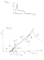
- FIGs 2 to 4 show profiles of currents I, I' through the actuator unit 36 of the injection valve 10 to illustrate the method for monitoring the injection valve 10 and the method for operating the injection valve 10. Furthermore, Figure 4 shows profiles of fluid quantities Q, Q' delivered by the injection valve 10.
- the method for monitoring an opening of the injection valve 10 comprises the following steps:
- the starting time T_0 is phased with operating conditions given by the combustion engine.
- a first gradient G_1 of the profile of the current I is detected.
- the gradient of the recorded profile of the current I changes more than a first given threshold.
- the first gradient G_1 is representative for an energization of the coil 38 between the starting time T_0 and the first gradient alteration time T_1.
- a second gradient G_2 of the profile of the current I is detected.
- the second gradient G_2 is representative for a movement of the armature 22 prior to engage the valve needle 20.
- the second gradient alteration timeT_2 is representative for an engagement of the armature 22 with the valve needle 20 and a start of an opening movement of the valve needle 20.
- a third gradient G_3 of the profile of the current I is detected.
- the third gradient G_3 is representative for a common movement of the armature 22 and the valve needle 20.
- the third gradient alteration time T_3 is representative for a complete opening of the valve needle 20 at its maximum lift position.
- a fourth gradient G_4 of the profile of the current I is detected.
- the method allows identifying the different positions of the armature 22 or common positions of the armature 22 and the valve needle 20. Due to this method it is possible for an injection valve 10 to exactly detect the movement of the armature 22 and the movement of the armature 22 combined with the valve needle 20. In particular, it is possible to detect the exact beginning and end of each individual movement of the armature 22 and the valve needle 20 by the gradient changes of the current profile.
- the drift shows a delay of the time T_1' (point P1'), which is representative for the beginning of the movement of the armature 22.
- This delayed initial movement of the armature 22 introduces a delay of the movement of the needle 20 (point P2' at the time T_2').
- the fluid quantity Q' delivered by the aged injection valve 10 with the time drift may be smaller than the original fluid quantity Q of the original injection valve 10 as shown in Figure 4 .
- FIG. 5 shows a flowchart to illustrate the method for operating the injection valve 10. The method comprises the following steps:
- step S12 the first gradient G_1 of the recorded profile of the current I which is representative for an energization of the coil 38 and the first gradient alteration time T_1 where the gradient of the recorded profile of the current I changes are detected.
- step S14 the second gradient G_2 of the profile of the current I which is representative for a movement of the armature 22 separate from the valve needle 20 and the second gradient alteration time T_2 are detected.
- step S16 time differences between the starting time T_0 and the first gradient alteration time T_1 and/or between the starting time T_0 and the second gradient alteration time T_2 are calculated. Furthermore, it is checked and verified if compensation is necessary by adapting the voltage signal V. If the time differences between the starting time T_0 and the first gradient alteration time T_1 and/or the starting time T_0 and the second gradient alteration time T_2 exceed given values the drift of the points P1, P2 may be compensated.
- An electronic control unit ECU may calculate the difference from the original data and may compensate the drift (step S18).
- an assignment rule for determining the signal duration time T_SIG of the voltage signal V is adjusted dependent from the time difference between the starting time T_0 and the first gradient alteration time T_1 and/or the starting time T_0 and the second gradient alteration time T_2.
- an assignment rule for determining a phase shift of the voltage signal V relative to the given crank shaft angle is adjusted so that a drift in particular of the first gradient alteration time T_1 and/or the second gradient alteration time T_2 may be compensated.
- the injection time may be adapted during a ballistic operating condition of the injection valve 10. By this, a corrected quantity Q of fluid may be delivered.
- step 20 If the time difference between the starting time T_0 and the first gradient alteration time T_1 and the time difference between the starting time T_0 and the second gradient alteration time T_2 does not exceed given values the previous data are used (step 20).
- Changes of the times T_1, T_2 and T_3 due to variable operating conditions or due to lifetime performance degradation are detectable and a specific algorithm could be applied to compensate the drift of the injection valve 10 or to reduce a variability between different cylinders of the combustion engine.
- a software program may modify injection parameters to compensate the drift and keep constant the delivered fuel quantity during the lifetime of the injection valve 10. By this method it is possible to obtain a minimum of the lowest controllable and deliverable fuel quantity including a predictable ballistic operating condition of the injection valve 10 after the second gradient alteration time T_2.
Landscapes
- Engineering & Computer Science (AREA)
- Chemical & Material Sciences (AREA)
- Combustion & Propulsion (AREA)
- Mechanical Engineering (AREA)
- General Engineering & Computer Science (AREA)
- Analytical Chemistry (AREA)
- Physics & Mathematics (AREA)
- Electromagnetism (AREA)
- Fuel-Injection Apparatus (AREA)
- Electrical Control Of Air Or Fuel Supplied To Internal-Combustion Engine (AREA)
Abstract
Method for monitoring an opening of an injection valve comprising a movable valve needle and preventing a fluid flow through a fluid outlet portion in a closing position and releasing the fluid flow through the fluid outlet portion in further positions, and an actuator unit with a coil and an armature, the armature being movable and being designed to actuate the valve needle. The method comprising the steps: actuating the actuator unit with a predetermined voltage signal at a given starting time, recording the current through the actuator unit, based on the recorded current and the starting time T_0 detecting a time T_1 where the gradient of the recorded profile of the current changes more than a first given threshold, based on the first gradient alteration time T_1 detecting a second time T_2 where the gradient of the recorded profile of the current changes more than a second given threshold, and dependent from the first time T_1 and the second time T_2 determining a diagnostic value which is representative for an erroneous respectively correct operation of the injection valve.
Description
- The invention relates to a method for monitoring an injection valve. Furthermore, the invention relates to a method for operating an injection valve.
- Injection valves are in wide spread use, in particular for internal combustion engines where they may be arranged in order to dose the fluid into an intake manifold of the internal combustion engine or directly into the combustion chamber of a cylinder of the internal combustion engine.
- Injection valves are manufactured in various forms in order to satisfy the various needs for the various combustion engines. Therefore, for example, their length, their diameter and also various elements of the injection valve being responsible for the way the fluid is dosed may vary in a wide range. In addition to that, injection valves may accommodate an actuator for actuating a needle of the injection valve, which may, for example, be an electromagnetic actuator or piezo electric actuator.
- In order to enhance the combustion process in view of the creation of unwanted emissions, the respective injection valve may be suited to dose fluids under very high pressures. The pressures may be in case of a gasoline engine, for example, in the range of up to 200 bar and in the case of Diesel engines in the range of more than 2000 bar.
- The object of the invention is to provide a method for monitoring an opening of an injection valve and a method for operating an injection valve which allow a reliable operation of the injection valve.
- This object is achieved by the features of the independent claims. Advantageous embodiments of the invention are given in the sub-claims.
- According to a first aspect the invention is distinguished by a method for monitoring an opening of an injection valve, the injection valve comprising a valve body with a cavity comprising a fluid outlet portion, a valve needle movable in the cavity and preventing a fluid flow through the fluid outlet portion in a closing position and releasing the fluid flow through the fluid outlet portion in further positions, and an actuator unit with a coil and an armature, the armature being movable in the cavity and being designed to actuate the valve needle. The method comprises the following steps: actuating the actuator unit by means of a predetermined voltage signal starting at a given starting time, recording a time-dependent profile of a current through the actuator unit, based on the recorded profile of the current and starting from the starting time detecting a first gradient alteration time where the gradient of the recorded profile of the current changes more than a first given threshold, based on the recorded profile of the current and starting from the first gradient alteration time detecting a second gradient alteration time where the gradient of the recorded profile of the current changes more than a second given threshold, and dependent from the first gradient alteration time and/or the second gradient alteration time determining a diagnostic value which is representative for an erroneous respectively correct operation of the injection valve.
- A first gradient of the recorded profile of the current between the starting time and the first gradient alteration time is representative for an energization of the coil. A second gradient of the recorded profile of the current between the first gradient alteration time and the second gradient alteration time is representative for a movement of the armature separate from the valve needle. The thresholds may be determined in advance in a suitable manner, for example by tests at an engine test station or by simulations.
- This method has the advantage that different phases of the operation of the injection valve during the opening of the injection valve may be identified. Consequently, a long-term drift of the behaviour of the injection valve during the opening process of the valve needle may be detected. Furthermore, the monitoring of the dynamics of the injection valve may serve as a base for a compensation of the long-term drift of the injection valve.
- In an advantageous embodiment of the invention the diagnostic value is determined dependent from the time difference between the starting time and the first gradient alteration time and/or the time difference between the starting time and the second gradient alteration time.
- In a further advantageous embodiment of the invention based on the recorded profile of the current and starting from the second gradient alteration time a third gradient alteration time is detected where the gradient of the recorded profile of the current changes more than a third given threshold, and the diagnostic value is determined dependent from the third gradient alteration time.
- A third gradient of the recorded profile of the current between the second gradient alteration time and the third gradient alteration time is representative for a common movement of the armature and the valve needle.
- This has the advantage that a further gradient alteration may be used to detect a long-term drift of the injection valve during the opening process of the valve needle.
- In a further advantageous embodiment of the invention the diagnostic value is determined dependent from the time difference between the starting time and the third gradient alteration time.
- According to a second aspect the invention is distinguished by a method for operating an injection valve of an internal combustion engine, the injection valve comprising a valve body with a cavity comprising a fluid outlet portion, a valve needle movable in the cavity and preventing a fluid flow through the fluid outlet portion in a closing position and releasing the fluid flow through the fluid outlet portion in further positions, and an actuator unit with a coil and an armature, the armature being movable in the cavity and being designed to actuate the valve needle. The method comprises the following steps: for a first injection process actuating the actuator unit by means of a predetermined voltage signal starting at a given starting time relative to a given crank shaft angle of the internal combustion engine, recording a time-dependent profile of a current through the actuator unit, based on the recorded profile of the current and the starting time detecting a first gradient alteration time where the gradient of the recorded profile of the current changes more than a first given threshold, based on the recorded profile of the current and starting from the first gradient alteration time detecting a second gradient alteration time where the gradient of the recorded profile of the current changes more than a second given threshold, and dependent from the first gradient alteration time and/or the second gradient alteration time adjusting an assignment rule for determining a signal duration time of the voltage signal for at least one further injection process.
- A first gradient of the recorded profile of the current between the starting time and the first gradient alteration time is representative for an energization of the coil. A second gradient of the recorded profile of the current between the first gradient alteration time and the second gradient alteration time is representative for a movement of the armature separate from the valve needle.
- This method has the advantage that a drift of the behaviour of the injection valve during the opening of the valve needle and a drift of the dynamics of the injection valve may be compensated by adapting the signal duration time of the voltage signal for the actuation of the actuator unit. This has the advantage that the delivered amount of fuel of the injection valve may be adjusted. Consequently, a long term stability of the amount of fuel delivered by the injection valve may be achieved.
- In an advantageous embodiment of the invention the assignment rule for determining the signal duration time of the voltage signal is adjusted dependent from the time difference between the starting time and the first gradient alteration time and/or the time difference between the starting time and the second gradient alteration time.
- In a further advantageous embodiment of the invention dependent from the first gradient alteration time and/or the second gradient alteration time an assignment rule for determining a phase shift of the voltage signal relative to the given crank shaft angle is adjusted for at least one further injection process. This has the advantage that a drift of the behaviour of the injection valve during the opening of the valve needle and a drift of the dynamics of the injection valve may be compensated by adjusting the voltage signal relative to the given crank shaft angle.
- According to a third aspect the invention is distinguished by a method for operating an injection valve of an internal combustion engine, the injection valve comprising a valve body with a cavity comprising a fluid outlet portion, a valve needle movable in the cavity and preventing a fluid flow through the fluid outlet portion in a closing position and releasing the fluid flow through the fluid outlet portion in further positions, and an actuator unit with a coil and an armature, the armature being movable in the cavity and being designed to actuate the valve needle. The method comprises the following steps: for a first injection process actuating the actuator unit by means of a predetermined voltage signal starting at a given starting time relative to a given crank shaft angle of the internal combustion engine, recording a time-dependent profile of a current through the actuator unit, based on the recorded profile of the current and starting from the starting time detecting a first gradient alteration time where the gradient of the recorded profile of the current changes more than a first given threshold, based on the recorded profile of the current and starting from the first gradient alteration time detecting a second gradient alteration time where the gradient of the recorded profile of the current changes more than a second given threshold, and dependent from the first gradient alteration time and/or the second gradient alteration time adjusting an assignment rule for determining a phase shift of the voltage signal relative to the given crank shaft angle for at least one further injection process. This method has the advantage that a drift of the behaviour of the injection valve during the opening of the valve needle and a drift of the dynamics of the injection valve may be compensated by adjusting the voltage signal relative to the given crank shaft angle.
- In an advantageous embodiment of the invention the assignment rule for determining the time shift of the voltage signal relative to the given crank shaft angle is adjusted dependent from the time difference between the starting time and the first gradient alteration time and/or the time difference between the starting time and the second gradient alteration time.
- Exemplary embodiments of the invention are explained in the following with the aid of schematic drawings. These are as follows:
- Figure 1
- an injection valve in a longitudinal section view, and
- Figure 2
- current profile of the injection valve,
- Figure 3
- enlarged current profile of the injection valve,
- Figure 4
- further enlarged current profile and profile of injected fluid of the injection valve, and
- Figure 5
- flow chart of the method for operating the injection valve.
- Elements of the same design and function that appear in different illustrations are identified by the same reference character.
-
Figure 1 shows aninjection valve 10 that is in particular suitable for dosing fuel to an internal combustion engine. Theinjection valve 10 comprises in particular aninlet tube 12. - The
injection valve 10 comprises a valve body 14 with a central longitudinal axis L. A cavity 18 is arranged in the valve body 14. Theinjection valve 10 has ahousing 16. The cavity 18 takes in avalve needle 20 and anarmature 22. Thevalve needle 20 and thearmature 22 are axially movable in the cavity 18. - A
spring 24 is arranged in arecess 26 which is provided in theinlet tube 12. Thespring 24 is mechanically coupled to thevalve needle 20. Thevalve needle 20 forms a first seat for thespring 24. - A
filter element 30 is arranged inside theinlet tube 12 and forms a further seat for thespring 24 . During the manufacturing process of theinjection valve 10 thefilter element 30 can be axially moved into theinlet tube 12 in order to preload thespring 24 in a desired manner. By this thespring 24 exerts a force on thevalve needle 20 towards aninjection nozzle 34 of theinjection valve 10. - In a closing position of the
valve needle 20 it sealingly rests on aseat plate 32 by this preventing a fluid flow through the at least oneinjection nozzle 34. Theinjection nozzle 34 may be, for example, an injection hole. - The
valve 10 is provided with anactuator unit 36 that is preferably an electro-magnetic actuator. The electro-magnetic actuator unit 36 comprises acoil 38, which is preferably arranged inside thehousing 16. Furthermore, the electro-magnetic actuator unit 36 comprises thearmature 22. The valve body 14, thehousing 16, theinlet tube 12 and thearmature 22 are forming an electromagnetic circuit. - A
fluid outlet portion 40 is a part of the cavity 18 near theseat plate 32. Thefluid outlet portion 40 communicates with afluid inlet portion 42 which is provided in the valve body 14. - In the following the function of the
injection valve 10 will be described: - Initially the fluid is led through the
filter element 30 to thefluid inlet portion 42 and further towards thefluid outlet portion 40. Thevalve needle 20 prevents a fluid flow through thefluid outlet portion 40 in a closing position of thevalve needle 20. Outside of the closing position of thevalve needle 20, thevalve needle 20 enables the fluid flow through thefluid outlet portion 40. - In the case when the electro-
magnetic actuator unit 36 with thecoil 38 gets energized theactuator unit 36 may affect an electro-magnetic force on thearmature 22. Thearmature 22 is attracted by the electro-magnetic actuator unit 36 with thecoil 38 and moves in axial direction away from thefluid outlet portion 40. Due to the mechanical coupling between thearmature 22 and thevalve needle 20 thearmature 22 takes thevalve needle 20 with it. Consequently, thevalve needle 20 moves in axial direction out of the closing position. Outside of the closing position of the valve needle 20 a gap between theseat plate 32 and thevalve needle 20 forms a fluid path and fluid can pass through theinjection nozzle 34. - In the case when the
actuator unit 36 is de-energized thespring 24 can force thevalve needle 20 to move in axial direction towards theinjection nozzle 34. Consequently, thevalve needle 20 may be forced to move in its closing position. It is depending on the force balance between the force on thevalve needle 20 caused by theactuator unit 36 with thecoil 38 and the force on thevalve needle 20 caused by thespring 24 whether thevalve needle 20 is in its closing position or not. -
Figures 2 to 4 show profiles of currents I, I' through theactuator unit 36 of theinjection valve 10 to illustrate the method for monitoring theinjection valve 10 and the method for operating theinjection valve 10. Furthermore,Figure 4 shows profiles of fluid quantities Q, Q' delivered by theinjection valve 10. - The method for monitoring an opening of the
injection valve 10 comprises the following steps: - The
actuator unit 36 is actuated by a predetermined voltage signal V which starts at a starting time T_0 (point P0). A time-dependent profile of the current I through theactuator unit 36 is recorded. The time-dependent profile of the current I is shown inFigure 2 . Detailed enlargements of this profile are shown inFigures 3 and4 . - The starting time T_0 is phased with operating conditions given by the combustion engine.
- Between the starting time T_0 and a first gradient alteration time T_1 (point P1) a first gradient G_1 of the profile of the current I is detected. At the first gradient alteration time T_1 the gradient of the recorded profile of the current I changes more than a first given threshold. The first gradient G_1 is representative for an energization of the
coil 38 between the starting time T_0 and the first gradient alteration time T_1. - Between the first gradient alteration time T_1 and a second gradient alteration time T_2 (point P2) a second gradient G_2 of the profile of the current I is detected. At the second gradient alteration time T_2 the gradient of the recorded profile of the current I changes more than a second given threshold. The second gradient G_2 is representative for a movement of the
armature 22 prior to engage thevalve needle 20. At the second gradient alteration time T_2 the gradient of the recorded profile of the current I changes again. The second gradient alteration timeT_2 is representative for an engagement of thearmature 22 with thevalve needle 20 and a start of an opening movement of thevalve needle 20. - Between the second gradient alteration time T_2 and a third gradient alteration time T_3 (point P3) a third gradient G_3 of the profile of the current I is detected. At the third gradient alteration time T_3 the gradient of the recorded profile of the current I changes more than a third given threshold. The third gradient G_3 is representative for a common movement of the
armature 22 and thevalve needle 20. The third gradient alteration time T_3 is representative for a complete opening of thevalve needle 20 at its maximum lift position. After the third gradient alteration time T_3 a fourth gradient G_4 of the profile of the current I is detected. - The method allows identifying the different positions of the
armature 22 or common positions of thearmature 22 and thevalve needle 20. Due to this method it is possible for aninjection valve 10 to exactly detect the movement of thearmature 22 and the movement of thearmature 22 combined with thevalve needle 20. In particular, it is possible to detect the exact beginning and end of each individual movement of thearmature 22 and thevalve needle 20 by the gradient changes of the current profile. - In the case of an
aged injection valve 10 the drift shows a delay of the time T_1' (point P1'), which is representative for the beginning of the movement of thearmature 22. This delayed initial movement of thearmature 22 introduces a delay of the movement of the needle 20 (point P2' at the time T_2'). By this the fluid quantity Q' delivered by theaged injection valve 10 with the time drift may be smaller than the original fluid quantity Q of theoriginal injection valve 10 as shown inFigure 4 . -
Figure 5 shows a flowchart to illustrate the method for operating theinjection valve 10. The method comprises the following steps: - In a first step S10 the
actuator unit 36 is actuated by the predetermined voltage signal V starting at the starting time T_0 relative to a given crank shaft angle of the internal combustion engine. The time-dependent profile of the current I for theactuator unit 36 is recorded. - In a further step S12 the first gradient G_1 of the recorded profile of the current I which is representative for an energization of the
coil 38 and the first gradient alteration time T_1 where the gradient of the recorded profile of the current I changes are detected. - In a further step S14 the second gradient G_2 of the profile of the current I which is representative for a movement of the
armature 22 separate from thevalve needle 20 and the second gradient alteration time T_2 are detected. - In a further step S16 time differences between the starting time T_0 and the first gradient alteration time T_1 and/or between the starting time T_0 and the second gradient alteration time T_2 are calculated. Furthermore, it is checked and verified if compensation is necessary by adapting the voltage signal V. If the time differences between the starting time T_0 and the first gradient alteration time T_1 and/or the starting time T_0 and the second gradient alteration time T_2 exceed given values the drift of the points P1, P2 may be compensated. An electronic control unit ECU may calculate the difference from the original data and may compensate the drift (step S18). In one embodiment of the method for operating the injection valve an assignment rule for determining the signal duration time T_SIG of the voltage signal V is adjusted dependent from the time difference between the starting time T_0 and the first gradient alteration time T_1 and/or the starting time T_0 and the second gradient alteration time T_2. In a further embodiment of the method for operating the
injection valve 10 an assignment rule for determining a phase shift of the voltage signal V relative to the given crank shaft angle is adjusted so that a drift in particular of the first gradient alteration time T_1 and/or the second gradient alteration time T_2 may be compensated. By this the injection time may be adapted during a ballistic operating condition of theinjection valve 10. By this, a corrected quantity Q of fluid may be delivered. - If the time difference between the starting time T_0 and the first gradient alteration time T_1 and the time difference between the starting time T_0 and the second gradient alteration time T_2 does not exceed given values the previous data are used (step 20).
- Changes of the times T_1, T_2 and T_3 due to variable operating conditions or due to lifetime performance degradation are detectable and a specific algorithm could be applied to compensate the drift of the
injection valve 10 or to reduce a variability between different cylinders of the combustion engine. A software program may modify injection parameters to compensate the drift and keep constant the delivered fuel quantity during the lifetime of theinjection valve 10. By this method it is possible to obtain a minimum of the lowest controllable and deliverable fuel quantity including a predictable ballistic operating condition of theinjection valve 10 after the second gradient alteration time T_2.
Claims (9)
- Method for monitoring an opening of an injection valve (10), the injection valve (10) comprising a valve body (14) with a cavity (18) comprising a fluid outlet portion (40), a valve needle (20) movable in the cavity (18) and preventing a fluid flow through the fluid outlet portion (40) in a closing position and releasing the fluid flow through the fluid outlet portion (40) in further positions, and an actuator unit (36) with a coil (38) and an armature (22), the armature (22) being movable in the cavity (18) and being designed to actuate the valve needle (20), the method comprising the following steps:- actuating the actuator unit (36) by means of a predetermined voltage signal (V) starting at a given starting time (T_0),- recording a time-dependent profile of a current (I) through the actuator unit (36),- based on the recorded profile of the current (I) and starting from the starting time (T_0) detecting a first gradient alteration time (T_1) where the gradient of the recorded profile of the current (I) changes more than a first given threshold,- based on the recorded profile of the current (I) and starting from the first gradient alteration time (T_1) detecting a second gradient alteration time (T_2) where the gradient of the recorded profile of the current (I) changes more than a second given threshold, and- dependent from the first gradient alteration time (T_1) and/or the second gradient alteration time (T_2) determining a diagnostic value which is representative for an erroneous respectively correct operation of the injection valve (10).
- Method according to claim 1, wherein the diagnostic value is determined dependent from the time difference between the starting time (T 0) and the first gradient alteration time (T_1) and/or the time difference between the starting time (T_0) and the second gradient alteration time (T_2).
- Method according to claim 1 or 2, wherein based on the recorded profile of the current (I) and starting from the second gradient alteration time (T_2) a third gradient alteration time (T_3) is detected where the gradient of the recorded profile of the current (I) changes more than a third given threshold, and the diagnostic value is determined dependent from the third gradient alteration time (T_3).
- Method according to claim 3, wherein the diagnostic value is determined dependent from the time difference between the starting time (T_0) and the third gradient alteration time (T_3).
- Method for operating an injection valve (10) of an internal combustion engine, the injection valve (10) comprising a valve body (14) with a cavity (18) comprising a fluid outlet portion (40), a valve needle (20) movable in the cavity (18) and preventing a fluid flow through the fluid outlet portion (40) in a closing position and releasing the fluid flow through the fluid outlet portion (40) in further positions, and an actuator unit (36) with a coil (38) and an armature (22), the armature (22) being movable in the cavity (18) and being designed to actuate the valve needle (20),
the method comprising the following steps:- for a first injection process actuating the actuator unit (36) by means of a predetermined voltage signal (V) starting at a given starting time (T_0) relative to a given crank shaft angle of the internal combustion engine,- recording a time-dependent profile of a current (I) through the actuator unit (36),- based on the recorded profile of the current (I) and starting from the starting time (T_0) detecting a first gradient alteration time (T_1) where the gradient of the recorded profile of the current (I) changes more than a first given threshold,- based on the recorded profile of the current (I) and starting from the first gradient alteration time (T_1) detecting a second gradient alteration time (T_2) where the gradient of the recorded profile of the current (I) changes more than a second given threshold, and- dependent from the first gradient alteration time (T_1) and/or the second gradient alteration time (T_2) adjusting an assignment rule for determining a signal duration time (T_SIG) of the voltage signal (V) for at least one further injection process. - Method according to claim 5, wherein the assignment rule for determining the signal duration time (T_SIG) of the voltage signal (V) is adjusted dependent from the time difference between the starting time (T_0) and the first gradient alteration time (T_1) and/or the time difference between the starting time (T_0) and the second gradient alteration time (T_2).
- Method according to claim 5, wherein dependent from the first gradient alteration time (T_1) and/or the second gradient alteration time (T_2) an assignment rule for determining a phase shift of the voltage signal (V) relative to the given crank shaft angle is adjusted for at least one further injection process.
- Method for operating an injection valve (10) of an internal combustion engine, the injection valve (10) comprising a valve body (14) with a cavity (18) comprising a fluid outlet portion (40), a valve needle (20) movable in the cavity (18) and preventing a fluid flow through the fluid outlet portion (40) in a closing position and releasing the fluid flow through the fluid outlet portion (40) in further positions, and an actuator unit (36) with a coil (38) and an armature (22), the armature (22) being movable in the cavity (18) and being designed to actuate the valve needle (20),
the method comprising the following steps:- for a first injection process actuating the actuator unit (36) by means of a predetermined voltage signal (V) starting at a given starting time (T_0) relative to a given crank shaft angle of the internal combustion engine,- recording a time-dependent profile of a current (I) through the actuator unit (36),- based on the recorded profile of the current (I) and starting from the starting time (T_0) detecting a first gradient alteration time (T_1) where the gradient of the recorded profile of the current (I) changes more than a first given threshold,- based on the recorded profile of the current (I) and starting from the first gradient alteration time (T_1) detecting a second gradient alteration time (T_2) where the gradient of the recorded profile of the current (I) changes more than a second given threshold, and- dependent from the first gradient alteration time (T_1) and/or the second gradient alteration time (T_2) adjusting an assignment rule for determining a phase shift of the voltage signal (V) relative to the given crank shaft angle for at least one further injection process. - Method according to claim 7 or 8, wherein the assignment rule for determining the time shift of the voltage signal (V) relative to the given crank shaft angle is adjusted dependent from the time difference between the starting time (T_0) and the first gradient alteration time (T_1) and/or the time difference between the starting time (T_0) and the second gradient alteration time (T_2).
Priority Applications (6)
| Application Number | Priority Date | Filing Date | Title |
|---|---|---|---|
| EP20120167414 EP2662555A1 (en) | 2012-05-10 | 2012-05-10 | Method for monitoring an injection valve |
| CN201380024394.8A CN104271928B (en) | 2012-05-10 | 2013-05-08 | Method for monitoring an injection valve |
| US14/399,227 US9482196B2 (en) | 2012-05-10 | 2013-05-08 | Method for monitoring an injection valve, and method for operating an injection valve |
| EP13721747.7A EP2850307B1 (en) | 2012-05-10 | 2013-05-08 | Method for monitoring an injection valve |
| PCT/EP2013/059624 WO2013167675A1 (en) | 2012-05-10 | 2013-05-08 | Method for monitoring an injection valve |
| KR1020147032582A KR20150018519A (en) | 2012-05-10 | 2013-05-08 | Method for monitoring an injection valve |
Applications Claiming Priority (1)
| Application Number | Priority Date | Filing Date | Title |
|---|---|---|---|
| EP20120167414 EP2662555A1 (en) | 2012-05-10 | 2012-05-10 | Method for monitoring an injection valve |
Publications (1)
| Publication Number | Publication Date |
|---|---|
| EP2662555A1 true EP2662555A1 (en) | 2013-11-13 |
Family
ID=48407557
Family Applications (2)
| Application Number | Title | Priority Date | Filing Date |
|---|---|---|---|
| EP20120167414 Withdrawn EP2662555A1 (en) | 2012-05-10 | 2012-05-10 | Method for monitoring an injection valve |
| EP13721747.7A Not-in-force EP2850307B1 (en) | 2012-05-10 | 2013-05-08 | Method for monitoring an injection valve |
Family Applications After (1)
| Application Number | Title | Priority Date | Filing Date |
|---|---|---|---|
| EP13721747.7A Not-in-force EP2850307B1 (en) | 2012-05-10 | 2013-05-08 | Method for monitoring an injection valve |
Country Status (5)
| Country | Link |
|---|---|
| US (1) | US9482196B2 (en) |
| EP (2) | EP2662555A1 (en) |
| KR (1) | KR20150018519A (en) |
| CN (1) | CN104271928B (en) |
| WO (1) | WO2013167675A1 (en) |
Cited By (4)
| Publication number | Priority date | Publication date | Assignee | Title |
|---|---|---|---|---|
| WO2015150015A1 (en) * | 2014-04-03 | 2015-10-08 | Continental Automotive Gmbh | Method and device for detecting the commencement of opening of a nozzle needle |
| WO2016119919A1 (en) * | 2015-01-28 | 2016-08-04 | Robert Bosch Gmbh | Operating method and actuation device for a piston pump |
| CN109072837A (en) * | 2016-04-18 | 2018-12-21 | 大陆汽车有限公司 | Method and motor vehicle for operating a common rail piezoelectrically operated servo injector of a diesel engine |
| US11167738B2 (en) | 2014-05-09 | 2021-11-09 | Continental Teves Ag & Co. Ohg | Method for improving the control behavior of an electronic motor vehicle braking system |
Families Citing this family (9)
| Publication number | Priority date | Publication date | Assignee | Title |
|---|---|---|---|---|
| EP2662555A1 (en) | 2012-05-10 | 2013-11-13 | Continental Automotive GmbH | Method for monitoring an injection valve |
| JP6327195B2 (en) * | 2015-04-27 | 2018-05-23 | 株式会社デンソー | Control device |
| GB201511007D0 (en) * | 2015-06-23 | 2015-08-05 | Delphi Int Operations Lux Srl | Nozzle assembly with adaptive closed signal |
| US10401398B2 (en) * | 2017-03-03 | 2019-09-03 | Woodward, Inc. | Fingerprinting of fluid injection devices |
| JP6614201B2 (en) * | 2017-05-19 | 2019-12-04 | 株式会社デンソー | Fuel injection control device |
| JP6720935B2 (en) * | 2017-07-28 | 2020-07-08 | 株式会社Soken | Fuel injection control device and fuel injection control method |
| WO2019102807A1 (en) * | 2017-11-24 | 2019-05-31 | 日立オートモティブシステムズ株式会社 | Fuel injection control device and fuel injection control method |
| US11073105B2 (en) | 2018-10-02 | 2021-07-27 | Rohr, Inc. | Acoustic torque box |
| JP7435430B2 (en) * | 2020-12-14 | 2024-02-21 | 株式会社デンソー | injection control device |
Citations (4)
| Publication number | Priority date | Publication date | Assignee | Title |
|---|---|---|---|---|
| DE4122348A1 (en) * | 1990-07-06 | 1992-01-23 | Jatco Corp | SOLENOID VALVE FAILURE DETECTING DEVICE |
| WO1994013991A1 (en) * | 1992-12-08 | 1994-06-23 | Pi Research Ltd. | Electromagnetic valves |
| US20080148831A1 (en) * | 2006-10-27 | 2008-06-26 | Ford Motor Company | Methods and systems for testing electromagnetically actuated fuel injectors |
| DE102009045307A1 (en) * | 2009-10-02 | 2011-04-07 | Robert Bosch Gmbh | Method and control device for operating a valve |
Family Cites Families (12)
| Publication number | Priority date | Publication date | Assignee | Title |
|---|---|---|---|---|
| DE19719602A1 (en) * | 1997-05-09 | 1998-11-12 | Fahrzeugklimaregelung Gmbh | Electronic control circuit |
| JP2000179391A (en) | 1998-12-16 | 2000-06-27 | Denso Corp | Solenoid valve drive |
| DE19936944A1 (en) * | 1999-08-05 | 2001-02-08 | Bosch Gmbh Robert | Method for metering fuel using a fuel injector |
| GB0616713D0 (en) | 2006-08-23 | 2006-10-04 | Delphi Tech Inc | Piezoelectric fuel injectors |
| JP4623066B2 (en) * | 2007-08-31 | 2011-02-02 | 株式会社デンソー | Injection control device for internal combustion engine |
| DE102008023373B4 (en) | 2008-05-13 | 2010-04-08 | Continental Automotive Gmbh | Method of controlling an injector, fuel injection system and internal combustion engine |
| DE102008061586B4 (en) | 2008-12-11 | 2015-08-20 | Continental Automotive Gmbh | Method and device for controlling a solid state actuator |
| DE102009002483A1 (en) * | 2009-04-20 | 2010-10-21 | Robert Bosch Gmbh | Method for operating an injection valve |
| DE102011083068A1 (en) * | 2011-09-20 | 2013-03-21 | Robert Bosch Gmbh | Method for determining a value of a stream |
| US9103294B2 (en) * | 2011-12-02 | 2015-08-11 | Cummins Inc. | Fuel drift estimation and compensation for operation of an internal combustion engine |
| EP2662555A1 (en) | 2012-05-10 | 2013-11-13 | Continental Automotive GmbH | Method for monitoring an injection valve |
| JP5874607B2 (en) * | 2012-11-05 | 2016-03-02 | 株式会社デンソー | Fuel injection control device and fuel injection system |
-
2012
- 2012-05-10 EP EP20120167414 patent/EP2662555A1/en not_active Withdrawn
-
2013
- 2013-05-08 CN CN201380024394.8A patent/CN104271928B/en not_active Expired - Fee Related
- 2013-05-08 WO PCT/EP2013/059624 patent/WO2013167675A1/en not_active Ceased
- 2013-05-08 EP EP13721747.7A patent/EP2850307B1/en not_active Not-in-force
- 2013-05-08 KR KR1020147032582A patent/KR20150018519A/en not_active Abandoned
- 2013-05-08 US US14/399,227 patent/US9482196B2/en not_active Expired - Fee Related
Patent Citations (4)
| Publication number | Priority date | Publication date | Assignee | Title |
|---|---|---|---|---|
| DE4122348A1 (en) * | 1990-07-06 | 1992-01-23 | Jatco Corp | SOLENOID VALVE FAILURE DETECTING DEVICE |
| WO1994013991A1 (en) * | 1992-12-08 | 1994-06-23 | Pi Research Ltd. | Electromagnetic valves |
| US20080148831A1 (en) * | 2006-10-27 | 2008-06-26 | Ford Motor Company | Methods and systems for testing electromagnetically actuated fuel injectors |
| DE102009045307A1 (en) * | 2009-10-02 | 2011-04-07 | Robert Bosch Gmbh | Method and control device for operating a valve |
Cited By (9)
| Publication number | Priority date | Publication date | Assignee | Title |
|---|---|---|---|---|
| WO2015150015A1 (en) * | 2014-04-03 | 2015-10-08 | Continental Automotive Gmbh | Method and device for detecting the commencement of opening of a nozzle needle |
| US10174701B2 (en) | 2014-04-03 | 2019-01-08 | Continental Automotive Gmbh | Method and device for detecting the commencement of opening of a nozzle needle |
| US11167738B2 (en) | 2014-05-09 | 2021-11-09 | Continental Teves Ag & Co. Ohg | Method for improving the control behavior of an electronic motor vehicle braking system |
| WO2016119919A1 (en) * | 2015-01-28 | 2016-08-04 | Robert Bosch Gmbh | Operating method and actuation device for a piston pump |
| CN107208566A (en) * | 2015-01-28 | 2017-09-26 | 罗伯特·博世有限公司 | Method for operation and actuation device for a piston pump |
| CN107208566B (en) * | 2015-01-28 | 2021-04-02 | 罗伯特·博世有限公司 | Method for operating and actuating device for a piston pump |
| US10989186B2 (en) | 2015-01-28 | 2021-04-27 | Robert Bosch Gmbh | Operating method and actuation device for a piston pump |
| CN109072837A (en) * | 2016-04-18 | 2018-12-21 | 大陆汽车有限公司 | Method and motor vehicle for operating a common rail piezoelectrically operated servo injector of a diesel engine |
| US10746120B2 (en) | 2016-04-18 | 2020-08-18 | Continental Automotive Gmbh | Diesel common-rail piezo-operated servo injector |
Also Published As
| Publication number | Publication date |
|---|---|
| US9482196B2 (en) | 2016-11-01 |
| KR20150018519A (en) | 2015-02-23 |
| US20150108238A1 (en) | 2015-04-23 |
| WO2013167675A1 (en) | 2013-11-14 |
| EP2850307A1 (en) | 2015-03-25 |
| EP2850307B1 (en) | 2016-10-19 |
| CN104271928A (en) | 2015-01-07 |
| CN104271928B (en) | 2017-01-18 |
Similar Documents
| Publication | Publication Date | Title |
|---|---|---|
| EP2850307B1 (en) | Method for monitoring an injection valve | |
| KR101784735B1 (en) | Determining the closing point in time of an injection valve on the basis of an analysis of the actuating voltage using an adapted reference voltage signal | |
| US7930089B2 (en) | Controller for a solenoid operated valve | |
| EP2685074A1 (en) | Fuel injection control in an internal combustion engine | |
| JP6520814B2 (en) | Fuel injection control device | |
| CN104632445A (en) | Method for detecting an error in the opening behavior of an injector | |
| KR101863903B1 (en) | Method and apparatus for operating an injection valve | |
| JP2019210933A (en) | Method for determining closing point of electromagnetic fuel injector | |
| CN103119271A (en) | Determination of the ballistic trajectory of an electromagnetically driven armature of a coil actuator | |
| CN104350262B (en) | Method for running valve | |
| EP2282043A1 (en) | Fluid injector and method and apparatus for operating the fluid injector | |
| EP2455600A1 (en) | Method and apparatus for operating an injection valve | |
| EP3011160B1 (en) | Method and device for controlling an injector | |
| CN105317575B (en) | Method for controlling multiple injections in fuel injection systems, in particular internal combustion engines | |
| JP6498293B2 (en) | Injection valve for injecting fluid, method of using the injection valve, and method of manufacturing the injection valve | |
| CN101529070A (en) | Method for determining a characteristic map of the injection quantity against an electrical variable of an electrically activated injection valve | |
| CN109555614B (en) | Method for calibrating a force or pressure sensor | |
| US9559286B2 (en) | Positioning device | |
| KR20170064411A (en) | Learning Method for Closing Time of An Injector | |
| CN107810319A (en) | For the method for the operation for monitoring piezoelectric injector | |
| US10233858B2 (en) | Method and device for determining the minimum hydraulic injection interval of a piezo-servo injector | |
| EP2607680A1 (en) | Method for manufacturing an injection valve | |
| KR101826691B1 (en) | Compensation Method for Closing Time of Injector | |
| KR101787037B1 (en) | Injection Control Method When Learning An Injector Closing Time and Injection Control System thereof | |
| CN103492695A (en) | Method and device for operating a piezo actuator |
Legal Events
| Date | Code | Title | Description |
|---|---|---|---|
| PUAI | Public reference made under article 153(3) epc to a published international application that has entered the european phase |
Free format text: ORIGINAL CODE: 0009012 |
|
| AK | Designated contracting states |
Kind code of ref document: A1 Designated state(s): AL AT BE BG CH CY CZ DE DK EE ES FI FR GB GR HR HU IE IS IT LI LT LU LV MC MK MT NL NO PL PT RO RS SE SI SK SM TR |
|
| AX | Request for extension of the european patent |
Extension state: BA ME |
|
| STAA | Information on the status of an ep patent application or granted ep patent |
Free format text: STATUS: THE APPLICATION IS DEEMED TO BE WITHDRAWN |
|
| 18D | Application deemed to be withdrawn |
Effective date: 20140514 |