EP2662501A2 - A method and a system for leak protection of a supply water installation - Google Patents
A method and a system for leak protection of a supply water installation Download PDFInfo
- Publication number
- EP2662501A2 EP2662501A2 EP13388004.7A EP13388004A EP2662501A2 EP 2662501 A2 EP2662501 A2 EP 2662501A2 EP 13388004 A EP13388004 A EP 13388004A EP 2662501 A2 EP2662501 A2 EP 2662501A2
- Authority
- EP
- European Patent Office
- Prior art keywords
- signal
- building
- water
- control box
- leak
- Prior art date
- Legal status (The legal status is an assumption and is not a legal conclusion. Google has not performed a legal analysis and makes no representation as to the accuracy of the status listed.)
- Granted
Links
Images
Classifications
-
- E—FIXED CONSTRUCTIONS
- E03—WATER SUPPLY; SEWERAGE
- E03B—INSTALLATIONS OR METHODS FOR OBTAINING, COLLECTING, OR DISTRIBUTING WATER
- E03B7/00—Water main or service pipe systems
- E03B7/07—Arrangement of devices, e.g. filters, flow controls, measuring devices, siphons or valves, in the pipe systems
- E03B7/071—Arrangement of safety devices in domestic pipe systems, e.g. devices for automatic shut-off
-
- Y—GENERAL TAGGING OF NEW TECHNOLOGICAL DEVELOPMENTS; GENERAL TAGGING OF CROSS-SECTIONAL TECHNOLOGIES SPANNING OVER SEVERAL SECTIONS OF THE IPC; TECHNICAL SUBJECTS COVERED BY FORMER USPC CROSS-REFERENCE ART COLLECTIONS [XRACs] AND DIGESTS
- Y02—TECHNOLOGIES OR APPLICATIONS FOR MITIGATION OR ADAPTATION AGAINST CLIMATE CHANGE
- Y02A—TECHNOLOGIES FOR ADAPTATION TO CLIMATE CHANGE
- Y02A20/00—Water conservation; Efficient water supply; Efficient water use
- Y02A20/15—Leakage reduction or detection in water storage or distribution
Definitions
- the invention relates to a method for leak monitoring and protection in a supply water installation by monitoring the water consumption, wherein the water conduit is provided with a signal-emitting flow meter and a controlled shutoff valve, both of which are connected with a control box.
- Ordinary protection systems are provided with a control box which is in signal connection with a water meter, so that the water consumption may be monitored currently.
- a water meter may be a mechanical flow meter with a signal annunciator or an electronic flow meter.
- US 2003 192600 discloses a system in which a form of flow interrupter is incorporated, and where an alarm is initiated after a predetermined period of time.
- the extent of a leak thus depends on how fast and thereby how much water escapes at a leak, and is not a question of water volume. Thus, the system does not allow for the degree of the leak.
- a control box when receiving a signal from one or more movement sensors, will signal the shutoff valve to open the water supply to the installation, when individuals are thus present in the building.
- the system is changed from a so-called protection system to a monitoring system, the greatest possible certainty of water pressure for fire fighting is achieved.
- a movement sensor is disposed in the vicinity of fire alarm boxes, the movement sensor will reveal that individuals are present in the building, even though the leak protection system is activated.
- control box When, as stated in claim 3, the control box is in signal connection with remote alarm annunciators, it is ensured that in those periods where population of the building renders closing of the shutoff valve impossible through signals from the movement sensors, an alarm of a leak in the installation will be communicated to the person in charge or to supervising staff, who, at their discretion, may interfere to shut off the leak under safe conditions.
- control box is constructed such that monitoring takes place in two phases with their respective sensitivities, depending on whether the building is populated or depopulated, the best possible leak protection is achieved, it being moreover made possible to use the system in installations with fire alarm boxes or hose reels through forced opening of the valve when the building is populated.
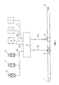
- the drawing shows an example of an installation in a building in which leak protection is desired, it being simultaneously desired to ensure that the system automatically switches to a monitoring system when individuals are present in the building.
- the drawing shows the supply pipe for pressure water, supply water, which is supplied, as indicated by the arrow 1.
- a water meter 2 is mounted on the pipe, said water meter registering, measuring, the water flow through the pipe.
- shutoff valve 3 is mounted, which controls the supply of water 8 to the supply water installation present in the building through a signal 3a from a control box 4.
- the control box 4 is in signal connection 5a with a plurality of movement sensors 5, which are mounted at selected places, e.g. in the vicinity of fire alarm boxes, extinguishing equipment and at access paths to tapping points in general.
- the purpose of these sensors 5 is to apply a signal 5a to the control box 4 when movement is registered, that is when individuals are present in the building.
- the control box 4 has two functions, phases, viz. monitoring of populated and depopulated building, respectively.
- Each of these two phases has its own monitoring and alarm threshold, so that the safety level as well as the practical aspect may be optimized
- the signal 5a from the movement sensors 5 to the control box 4 controls this by switching the consumption phases in the building.
- control box 4 When the water consumption thresholds fixed for the phase concerned are exceeded, the control box 4 will apply an alarm signal 7a to the remote alarm annunciator 7.
- control box 4 If the control box 4 is in the phase of depopulated building, and if no signal 6a arrives from the fire alarm 6, the control box 4 will apply a signal 3a to the valve 3 for shutting off the water supply 8.
- control box 4 If the control box 4 then receives a signal 5a from the movement sensors 5 or a signal 6a from the fire alarm 6, a signal 3a will immediately be applied for the opening of the valve 3 with a view to water pressure to the installation.
- the movement sensors 5 are preferably arranged at the access paths to tapping points of the supply water installations, and it is expedient to arrange a sensor 5 in front of each fire alarm box, hose reel. This ensures that these fire fighting installations, which are connected with the supply water installation, will always be under water pressure, even though the supply water installation is protected by the leak system.
- the leak protection system according to the invention will automatically exhibit the best possible protection degree, and the requirements of the authorities are met at the same time.
Landscapes
- Health & Medical Sciences (AREA)
- Life Sciences & Earth Sciences (AREA)
- Engineering & Computer Science (AREA)
- Hydrology & Water Resources (AREA)
- Public Health (AREA)
- Water Supply & Treatment (AREA)
- Fire-Extinguishing By Fire Departments, And Fire-Extinguishing Equipment And Control Thereof (AREA)
Abstract
Description
- The invention relates to a method for leak monitoring and protection in a supply water installation by monitoring the water consumption, wherein the water conduit is provided with a signal-emitting flow meter and a controlled shutoff valve, both of which are connected with a control box.
- Such methods and leak protection systems are widely used, since serious damage to buildings may occur, if a leak in the water installation is not detected rapidly, and the water is shut off.
- Ordinary protection systems are provided with a control box which is in signal connection with a water meter, so that the water consumption may be monitored currently. Such a water meter may be a mechanical flow meter with a signal annunciator or an electronic flow meter.
- Various systems for such leak protections are known.
-
US 2003 192600 discloses a system in which a form of flow interrupter is incorporated, and where an alarm is initiated after a predetermined period of time. - The extent of a leak thus depends on how fast and thereby how much water escapes at a leak, and is not a question of water volume. Thus, the system does not allow for the degree of the leak.
- Another system is known from
US 5,347,264 , in which a shutoff valve on the water conduit is in signal connection with movement sensors. This system however, is vitiated by the drawback that as long as a movement sensor is activated by individuals in the building, there will be no leak protection of the installation, since the valve is constantly open, and, thus, no form of measurement takes place. Only when the movement sensor has registered depopulation for a certain time, will the system close the valve and detect a leak, if any, by means of a pressostat. - It is the object of the method according to the invention to improve the level of protection in a building through the use of signals from one or more movement sensors, to adapt the sensitivity of the leak monitoring to the actual use of the building, as well as, where fire alarm boxes or hose reels connected to the ordinary supply water installation are present in the installation, to force the opening of the shutoff valve according to the same movement signals, so that closing is not possible irrespective of conflicting control signals. It is ensured thereby that the fire fighting means, as required by the Building Regulations, are under the necessary operating pressure when the building is populated.
- This is achieved according to the invention by a method in which a control box, when receiving a signal from one or more movement sensors, will signal the shutoff valve to open the water supply to the installation, when individuals are thus present in the building.
- This changes the system from being a leak protection system to a monitoring system, when individuals are registered in the building, which means that the system satisfies the requirements of fire fighting, it being ensured that there is water for fire fighting.
- This means that hose reels, fire alarm boxes will be under water pressure, when this is required, notwithstanding that the supply water installation is under control of a leak protection system.
- When, as stated in
claim 2, the system is changed from a so-called protection system to a monitoring system, the greatest possible certainty of water pressure for fire fighting is achieved. When a movement sensor is disposed in the vicinity of fire alarm boxes, the movement sensor will reveal that individuals are present in the building, even though the leak protection system is activated. - When, as stated in
claim 3, the control box is in signal connection with remote alarm annunciators, it is ensured that in those periods where population of the building renders closing of the shutoff valve impossible through signals from the movement sensors, an alarm of a leak in the installation will be communicated to the person in charge or to supervising staff, who, at their discretion, may interfere to shut off the leak under safe conditions. - When, as stated in
claim 4, the control box is constructed such that monitoring takes place in two phases with their respective sensitivities, depending on whether the building is populated or depopulated, the best possible leak protection is achieved, it being moreover made possible to use the system in installations with fire alarm boxes or hose reels through forced opening of the valve when the building is populated. - Finally, it is expedient, as stated in
claim 5, to allow movement sensors to control these two functions of the control box. - An example of a system for performing the method according to the invention will be described more fully below with reference to the drawing, which shows a basic diagram of a system mounted in a building.
- The drawing shows an example of an installation in a building in which leak protection is desired, it being simultaneously desired to ensure that the system automatically switches to a monitoring system when individuals are present in the building.
- Hereby, a dual function is achieved, depending on whether water pressure for fire fighting is needed.
- The drawing, at the bottom, shows the supply pipe for pressure water, supply water, which is supplied, as indicated by the arrow 1. A
water meter 2 is mounted on the pipe, said water meter registering, measuring, the water flow through the pipe. - Moreover, a
shutoff valve 3 is mounted, which controls the supply ofwater 8 to the supply water installation present in the building through a signal 3a from acontrol box 4. - The
control box 4 is in signal connection 5a with a plurality ofmovement sensors 5, which are mounted at selected places, e.g. in the vicinity of fire alarm boxes, extinguishing equipment and at access paths to tapping points in general. The purpose of thesesensors 5 is to apply a signal 5a to thecontrol box 4 when movement is registered, that is when individuals are present in the building. - Further, there is a signal connection 6a to an automatic fire alarm 6, which, in case of fire, will register it and apply a signal 6a to the
control box 4, which, influenced by this, will likewise force theshutoff valve 3 to open. Finally, twoboxes 7 are shown, which indicate remote alarm annunciators, so that an alarm is applied to the person in charge/supervising person at a leak from the supply water installation. - Then, the method, i.e. the function, will be described.
- The
control box 4 has two functions, phases, viz. monitoring of populated and depopulated building, respectively. - Each of these two phases has its own monitoring and alarm threshold, so that the safety level as well as the practical aspect may be optimized
- The signal 5a from the
movement sensors 5 to thecontrol box 4 controls this by switching the consumption phases in the building. - When the water consumption thresholds fixed for the phase concerned are exceeded, the
control box 4 will apply an alarm signal 7a to theremote alarm annunciator 7. - If the
control box 4 is in the phase of depopulated building, and if no signal 6a arrives from the fire alarm 6, thecontrol box 4 will apply a signal 3a to thevalve 3 for shutting off thewater supply 8. - If the
control box 4 then receives a signal 5a from themovement sensors 5 or a signal 6a from the fire alarm 6, a signal 3a will immediately be applied for the opening of thevalve 3 with a view to water pressure to the installation. - The
movement sensors 5 are preferably arranged at the access paths to tapping points of the supply water installations, and it is expedient to arrange asensor 5 in front of each fire alarm box, hose reel. This ensures that these fire fighting installations, which are connected with the supply water installation, will always be under water pressure, even though the supply water installation is protected by the leak system. - By means of this system and the method, the leak protection system according to the invention will automatically exhibit the best possible protection degree, and the requirements of the authorities are met at the same time.
Claims (5)
- A method of monitoring the water consumption and/or leakage in a supply water installation, wherein the water conduit is provided with a water meter and a shutoff valve, both of which are in signal connection with a control box, characterized in that when the box (4) receives a signal (5a) from one or more movement sensors (5), it will apply a signal (3a) to the shutoff valve (3) to open the water supply (8) to the installation when individuals are present in the building.
- A method according to claim 1, characterized in that the opening of the water supply (8) changes the system from being a protection system to a monitoring system, when individuals are present in the building.
- A method according to claims 1 and 2, characterized in that the control box (4) is in signal connection (7a and 7b) with one or more remote alarm annunciators (7), so that when the control box (4) is in a phase, function, corresponding to depopulated building, and no signal (6a) is applied from a fire alarm (6), the box (4) applies a signal (3a) to the valve (3) to shut off the water supply (8),
and when the control box (4) is in its second phase, function, corresponding to populated building, and a signal (5a) from one or more movement sensors (5) and/or a signal (6a) from a fire alarm (6) is applied, the box (4) applies a signal (3a) to the valve (3) to open the water supply (8) to the building, and if the control box (4) at a signal (2a) from the water meter (2) registers a leak, it applies a signal (7a/7b) to remote alarm annunciators (7), and an alarm message is sent to the person in charge/supervising person, said shutoff valve (3) being forcibly open, for which reason the control box (4) cannot shut off the leak. - A means for performing the method according to claims 1 - 3, characterized in that the control box (4) is constructed for two phases, functions, viz. monitoring (2a) of the water consumption at a populated building and a depopulated building, respectively.
- A means according to claim 4, characterized in that a signal (5a) from the movement sensors (5) to the control box (4) determines the function.
Applications Claiming Priority (1)
| Application Number | Priority Date | Filing Date | Title |
|---|---|---|---|
| DKPA201200314 | 2012-05-08 |
Publications (3)
| Publication Number | Publication Date |
|---|---|
| EP2662501A2 true EP2662501A2 (en) | 2013-11-13 |
| EP2662501A3 EP2662501A3 (en) | 2015-11-25 |
| EP2662501B1 EP2662501B1 (en) | 2019-06-12 |
Family
ID=48625973
Family Applications (1)
| Application Number | Title | Priority Date | Filing Date |
|---|---|---|---|
| EP13388004.7A Active EP2662501B1 (en) | 2012-05-08 | 2013-04-23 | A method and a system for leak protection of a supply water installation |
Country Status (2)
| Country | Link |
|---|---|
| EP (1) | EP2662501B1 (en) |
| DK (1) | DK2662501T3 (en) |
Cited By (4)
| Publication number | Priority date | Publication date | Assignee | Title |
|---|---|---|---|---|
| GB2524589A (en) * | 2014-03-28 | 2015-09-30 | Sydney Edward Smith | Fluid control systems |
| CN106284483A (en) * | 2016-07-22 | 2017-01-04 | 汤美 | A kind of campus water-saving system |
| EP3406806A1 (en) * | 2017-05-26 | 2018-11-28 | Hans Sasserath GmbH & Co. KG. | Fitting assembly with connection piece and water treatment unit and method of treating drinking water |
| DK181517B1 (en) * | 2022-10-07 | 2024-03-22 | Dantaet As | Leak protection system and hose reel for water supply installations |
Citations (2)
| Publication number | Priority date | Publication date | Assignee | Title |
|---|---|---|---|---|
| US5347264A (en) | 1990-09-14 | 1994-09-13 | Rb Larmprodukter Ab | Method and apparatus for automatically controlling a water supply using movement detector means |
| US20030192600A1 (en) | 2002-04-11 | 2003-10-16 | Ford Michael Brent | Method and system for controlling a household water supply |
Family Cites Families (5)
| Publication number | Priority date | Publication date | Assignee | Title |
|---|---|---|---|---|
| FR2661971B1 (en) * | 1990-05-09 | 1992-09-18 | Balabeau Jerome | "SYSTEMICALLY CLOSED" SAFETY DEVICE FOR THE WATER SUPPLY WITH AUTOMATED ASSISTED OPENING IN THE ONLY CASE OF HUMAN PRESENCE - SYSTEM THAT MAY BE CALLED "ANTI-DAMAGE TO WATER DEVICE". |
| DE29611260U1 (en) * | 1996-06-30 | 1996-09-26 | Denk, Oliver, Dipl.-Ing., 44309 Dortmund | Device for shutting off fluids and gaseous substances |
| WO2008020407A2 (en) * | 2006-08-16 | 2008-02-21 | Classic Number Trading 47 (Pty) Ltd | Water supply management system |
| NO329802B1 (en) * | 2009-02-24 | 2010-12-20 | Vemund Eithun | System and method for leakage control and / or testing of piping and tapping points for non-compressible liquids |
| DE102009045150B3 (en) * | 2009-09-30 | 2011-06-16 | AFRISO-EURO-INDEX Gesellschaft mit beschränkter Haftung | Device for supplying water to e.g. tap of single-family home, has central stop valve that is opened only for valve opening timings associated with loads, where valve opening timings are stored in control unit |
-
2013
- 2013-04-23 EP EP13388004.7A patent/EP2662501B1/en active Active
- 2013-04-23 DK DK13388004.7T patent/DK2662501T3/en active
Patent Citations (2)
| Publication number | Priority date | Publication date | Assignee | Title |
|---|---|---|---|---|
| US5347264A (en) | 1990-09-14 | 1994-09-13 | Rb Larmprodukter Ab | Method and apparatus for automatically controlling a water supply using movement detector means |
| US20030192600A1 (en) | 2002-04-11 | 2003-10-16 | Ford Michael Brent | Method and system for controlling a household water supply |
Cited By (7)
| Publication number | Priority date | Publication date | Assignee | Title |
|---|---|---|---|---|
| GB2524589A (en) * | 2014-03-28 | 2015-09-30 | Sydney Edward Smith | Fluid control systems |
| CN106284483A (en) * | 2016-07-22 | 2017-01-04 | 汤美 | A kind of campus water-saving system |
| EP3406806A1 (en) * | 2017-05-26 | 2018-11-28 | Hans Sasserath GmbH & Co. KG. | Fitting assembly with connection piece and water treatment unit and method of treating drinking water |
| CN108946868A (en) * | 2017-05-26 | 2018-12-07 | 汉斯萨塞拉思有限责任两合公司 | For admixing the water accessory of processed drinking water |
| CN108946868B (en) * | 2017-05-26 | 2022-11-18 | 汉斯萨塞拉思有限责任两合公司 | Water fittings for blending treated drinking water |
| DK181517B1 (en) * | 2022-10-07 | 2024-03-22 | Dantaet As | Leak protection system and hose reel for water supply installations |
| DK202200915A1 (en) * | 2022-10-07 | 2024-03-22 | Dantaet As | Leak protection system for water supply installations with hose reel |
Also Published As
| Publication number | Publication date |
|---|---|
| EP2662501B1 (en) | 2019-06-12 |
| DK2662501T3 (en) | 2019-08-26 |
| EP2662501A3 (en) | 2015-11-25 |
Similar Documents
| Publication | Publication Date | Title |
|---|---|---|
| US11573150B2 (en) | Fluid leakage control apparatus, system and method | |
| EP0548243B1 (en) | Method and apparatus including movement detector in a monitoring system | |
| US20170100617A1 (en) | Devices, methods and systems for monitoring water-based fire sprinkler systems | |
| US20070095400A1 (en) | Shut-off valve system | |
| EP2662501B1 (en) | A method and a system for leak protection of a supply water installation | |
| US20130340836A1 (en) | Overflow protection system for a fluid transfer system | |
| US8439062B1 (en) | Flood preventing system, and method of use | |
| CN210035093U (en) | Pipeline leakage detection alarm device | |
| CN103272359A (en) | Real-time monitoring system and method for fire water supply system of building | |
| US11608619B2 (en) | Method and apparatus for isolating a pressure-driven system from a source | |
| WO2008042125A3 (en) | Apparatus, systems and methods for reliably detecting faults within a power distribution system | |
| US20090188683A1 (en) | Flow sensor and actuator | |
| JP6509624B2 (en) | Package type automatic fire extinguishing equipment | |
| US20200188714A1 (en) | Fire-Extinguishing Facility, Fire-Extinguishing System Comprising Same, and Method for Determining the Extent of a Fire | |
| KR102008618B1 (en) | Line resistance meter of fire-prevention facilities | |
| JP2012018502A (en) | Gas shutoff apparatus | |
| WO2010111981A3 (en) | Modular control and indicating panel, its use and a method of controlling building alarm systems | |
| JP5004170B2 (en) | Pre-actuated sprinkler fire extinguishing equipment | |
| KR20220117728A (en) | Water meter freeze protection apparatus | |
| US9360871B1 (en) | Integrated fluid flow management apparatus | |
| CN109893821A (en) | A kind of building detect fire-fighting system automatically | |
| DK181517B1 (en) | Leak protection system and hose reel for water supply installations | |
| JP2008093318A (en) | Fire extinguishing equipment | |
| WO2020089914A1 (en) | Automatic wireless electrical system for closing and opening water pipe | |
| RU2676503C2 (en) | Method of shutting off water supply to an emergency section of sprinkler plant (versions) and device for its implementation (versions) |
Legal Events
| Date | Code | Title | Description |
|---|---|---|---|
| PUAI | Public reference made under article 153(3) epc to a published international application that has entered the european phase |
Free format text: ORIGINAL CODE: 0009012 |
|
| AK | Designated contracting states |
Kind code of ref document: A2 Designated state(s): AL AT BE BG CH CY CZ DE DK EE ES FI FR GB GR HR HU IE IS IT LI LT LU LV MC MK MT NL NO PL PT RO RS SE SI SK SM TR |
|
| AX | Request for extension of the european patent |
Extension state: BA ME |
|
| PUAL | Search report despatched |
Free format text: ORIGINAL CODE: 0009013 |
|
| AK | Designated contracting states |
Kind code of ref document: A3 Designated state(s): AL AT BE BG CH CY CZ DE DK EE ES FI FR GB GR HR HU IE IS IT LI LT LU LV MC MK MT NL NO PL PT RO RS SE SI SK SM TR |
|
| AX | Request for extension of the european patent |
Extension state: BA ME |
|
| RIC1 | Information provided on ipc code assigned before grant |
Ipc: E03B 7/07 20060101AFI20151021BHEP |
|
| 17P | Request for examination filed |
Effective date: 20160525 |
|
| RAX | Requested extension states of the european patent have changed |
Extension state: ME Payment date: 20160525 Extension state: BA Payment date: 20160525 |
|
| RBV | Designated contracting states (corrected) |
Designated state(s): AL AT BE BG CH CY CZ DE DK EE ES FI FR GB GR HR HU IE IS IT LI LT LU LV MC MK MT NL NO PL PT RO RS SE SI SK SM TR |
|
| GRAP | Despatch of communication of intention to grant a patent |
Free format text: ORIGINAL CODE: EPIDOSNIGR1 |
|
| STAA | Information on the status of an ep patent application or granted ep patent |
Free format text: STATUS: GRANT OF PATENT IS INTENDED |
|
| INTG | Intention to grant announced |
Effective date: 20180704 |
|
| GRAJ | Information related to disapproval of communication of intention to grant by the applicant or resumption of examination proceedings by the epo deleted |
Free format text: ORIGINAL CODE: EPIDOSDIGR1 |
|
| STAA | Information on the status of an ep patent application or granted ep patent |
Free format text: STATUS: REQUEST FOR EXAMINATION WAS MADE |
|
| STAA | Information on the status of an ep patent application or granted ep patent |
Free format text: STATUS: EXAMINATION IS IN PROGRESS |
|
| INTC | Intention to grant announced (deleted) | ||
| 17Q | First examination report despatched |
Effective date: 20181026 |
|
| GRAP | Despatch of communication of intention to grant a patent |
Free format text: ORIGINAL CODE: EPIDOSNIGR1 |
|
| STAA | Information on the status of an ep patent application or granted ep patent |
Free format text: STATUS: GRANT OF PATENT IS INTENDED |
|
| GRAS | Grant fee paid |
Free format text: ORIGINAL CODE: EPIDOSNIGR3 |
|
| GRAA | (expected) grant |
Free format text: ORIGINAL CODE: 0009210 |
|
| STAA | Information on the status of an ep patent application or granted ep patent |
Free format text: STATUS: THE PATENT HAS BEEN GRANTED |
|
| INTG | Intention to grant announced |
Effective date: 20190418 |
|
| AK | Designated contracting states |
Kind code of ref document: B1 Designated state(s): AL AT BE BG CH CY CZ DE DK EE ES FI FR GB GR HR HU IE IS IT LI LT LU LV MC MK MT NL NO PL PT RO RS SE SI SK SM TR |
|
| AX | Request for extension of the european patent |
Extension state: BA ME |
|
| REG | Reference to a national code |
Ref country code: GB Ref legal event code: FG4D |
|
| REG | Reference to a national code |
Ref country code: CH Ref legal event code: EP |
|
| REG | Reference to a national code |
Ref country code: AT Ref legal event code: REF Ref document number: 1142703 Country of ref document: AT Kind code of ref document: T Effective date: 20190615 |
|
| REG | Reference to a national code |
Ref country code: DE Ref legal event code: R096 Ref document number: 602013056466 Country of ref document: DE |
|
| REG | Reference to a national code |
Ref country code: IE Ref legal event code: FG4D |
|
| REG | Reference to a national code |
Ref country code: DK Ref legal event code: T3 Effective date: 20190823 |
|
| REG | Reference to a national code |
Ref country code: NL Ref legal event code: MP Effective date: 20190612 |
|
| REG | Reference to a national code |
Ref country code: LT Ref legal event code: MG4D |
|
| PG25 | Lapsed in a contracting state [announced via postgrant information from national office to epo] |
Ref country code: LT Free format text: LAPSE BECAUSE OF FAILURE TO SUBMIT A TRANSLATION OF THE DESCRIPTION OR TO PAY THE FEE WITHIN THE PRESCRIBED TIME-LIMIT Effective date: 20190612 Ref country code: HR Free format text: LAPSE BECAUSE OF FAILURE TO SUBMIT A TRANSLATION OF THE DESCRIPTION OR TO PAY THE FEE WITHIN THE PRESCRIBED TIME-LIMIT Effective date: 20190612 Ref country code: SE Free format text: LAPSE BECAUSE OF FAILURE TO SUBMIT A TRANSLATION OF THE DESCRIPTION OR TO PAY THE FEE WITHIN THE PRESCRIBED TIME-LIMIT Effective date: 20190612 Ref country code: NO Free format text: LAPSE BECAUSE OF FAILURE TO SUBMIT A TRANSLATION OF THE DESCRIPTION OR TO PAY THE FEE WITHIN THE PRESCRIBED TIME-LIMIT Effective date: 20190912 Ref country code: AL Free format text: LAPSE BECAUSE OF FAILURE TO SUBMIT A TRANSLATION OF THE DESCRIPTION OR TO PAY THE FEE WITHIN THE PRESCRIBED TIME-LIMIT Effective date: 20190612 Ref country code: FI Free format text: LAPSE BECAUSE OF FAILURE TO SUBMIT A TRANSLATION OF THE DESCRIPTION OR TO PAY THE FEE WITHIN THE PRESCRIBED TIME-LIMIT Effective date: 20190612 Ref country code: ES Free format text: LAPSE BECAUSE OF FAILURE TO SUBMIT A TRANSLATION OF THE DESCRIPTION OR TO PAY THE FEE WITHIN THE PRESCRIBED TIME-LIMIT Effective date: 20190612 |
|
| PG25 | Lapsed in a contracting state [announced via postgrant information from national office to epo] |
Ref country code: BG Free format text: LAPSE BECAUSE OF FAILURE TO SUBMIT A TRANSLATION OF THE DESCRIPTION OR TO PAY THE FEE WITHIN THE PRESCRIBED TIME-LIMIT Effective date: 20190912 Ref country code: LV Free format text: LAPSE BECAUSE OF FAILURE TO SUBMIT A TRANSLATION OF THE DESCRIPTION OR TO PAY THE FEE WITHIN THE PRESCRIBED TIME-LIMIT Effective date: 20190612 Ref country code: RS Free format text: LAPSE BECAUSE OF FAILURE TO SUBMIT A TRANSLATION OF THE DESCRIPTION OR TO PAY THE FEE WITHIN THE PRESCRIBED TIME-LIMIT Effective date: 20190612 Ref country code: GR Free format text: LAPSE BECAUSE OF FAILURE TO SUBMIT A TRANSLATION OF THE DESCRIPTION OR TO PAY THE FEE WITHIN THE PRESCRIBED TIME-LIMIT Effective date: 20190913 |
|
| REG | Reference to a national code |
Ref country code: AT Ref legal event code: MK05 Ref document number: 1142703 Country of ref document: AT Kind code of ref document: T Effective date: 20190612 |
|
| PG25 | Lapsed in a contracting state [announced via postgrant information from national office to epo] |
Ref country code: EE Free format text: LAPSE BECAUSE OF FAILURE TO SUBMIT A TRANSLATION OF THE DESCRIPTION OR TO PAY THE FEE WITHIN THE PRESCRIBED TIME-LIMIT Effective date: 20190612 Ref country code: NL Free format text: LAPSE BECAUSE OF FAILURE TO SUBMIT A TRANSLATION OF THE DESCRIPTION OR TO PAY THE FEE WITHIN THE PRESCRIBED TIME-LIMIT Effective date: 20190612 Ref country code: SK Free format text: LAPSE BECAUSE OF FAILURE TO SUBMIT A TRANSLATION OF THE DESCRIPTION OR TO PAY THE FEE WITHIN THE PRESCRIBED TIME-LIMIT Effective date: 20190612 Ref country code: AT Free format text: LAPSE BECAUSE OF FAILURE TO SUBMIT A TRANSLATION OF THE DESCRIPTION OR TO PAY THE FEE WITHIN THE PRESCRIBED TIME-LIMIT Effective date: 20190612 Ref country code: CZ Free format text: LAPSE BECAUSE OF FAILURE TO SUBMIT A TRANSLATION OF THE DESCRIPTION OR TO PAY THE FEE WITHIN THE PRESCRIBED TIME-LIMIT Effective date: 20190612 Ref country code: RO Free format text: LAPSE BECAUSE OF FAILURE TO SUBMIT A TRANSLATION OF THE DESCRIPTION OR TO PAY THE FEE WITHIN THE PRESCRIBED TIME-LIMIT Effective date: 20190612 Ref country code: PT Free format text: LAPSE BECAUSE OF FAILURE TO SUBMIT A TRANSLATION OF THE DESCRIPTION OR TO PAY THE FEE WITHIN THE PRESCRIBED TIME-LIMIT Effective date: 20191014 |
|
| PG25 | Lapsed in a contracting state [announced via postgrant information from national office to epo] |
Ref country code: IS Free format text: LAPSE BECAUSE OF FAILURE TO SUBMIT A TRANSLATION OF THE DESCRIPTION OR TO PAY THE FEE WITHIN THE PRESCRIBED TIME-LIMIT Effective date: 20191012 Ref country code: SM Free format text: LAPSE BECAUSE OF FAILURE TO SUBMIT A TRANSLATION OF THE DESCRIPTION OR TO PAY THE FEE WITHIN THE PRESCRIBED TIME-LIMIT Effective date: 20190612 Ref country code: IT Free format text: LAPSE BECAUSE OF FAILURE TO SUBMIT A TRANSLATION OF THE DESCRIPTION OR TO PAY THE FEE WITHIN THE PRESCRIBED TIME-LIMIT Effective date: 20190612 |
|
| REG | Reference to a national code |
Ref country code: DE Ref legal event code: R097 Ref document number: 602013056466 Country of ref document: DE |
|
| PG25 | Lapsed in a contracting state [announced via postgrant information from national office to epo] |
Ref country code: TR Free format text: LAPSE BECAUSE OF FAILURE TO SUBMIT A TRANSLATION OF THE DESCRIPTION OR TO PAY THE FEE WITHIN THE PRESCRIBED TIME-LIMIT Effective date: 20190612 |
|
| PLBE | No opposition filed within time limit |
Free format text: ORIGINAL CODE: 0009261 |
|
| STAA | Information on the status of an ep patent application or granted ep patent |
Free format text: STATUS: NO OPPOSITION FILED WITHIN TIME LIMIT |
|
| PG25 | Lapsed in a contracting state [announced via postgrant information from national office to epo] |
Ref country code: PL Free format text: LAPSE BECAUSE OF FAILURE TO SUBMIT A TRANSLATION OF THE DESCRIPTION OR TO PAY THE FEE WITHIN THE PRESCRIBED TIME-LIMIT Effective date: 20190612 |
|
| 26N | No opposition filed |
Effective date: 20200313 |
|
| PG25 | Lapsed in a contracting state [announced via postgrant information from national office to epo] |
Ref country code: IS Free format text: LAPSE BECAUSE OF FAILURE TO SUBMIT A TRANSLATION OF THE DESCRIPTION OR TO PAY THE FEE WITHIN THE PRESCRIBED TIME-LIMIT Effective date: 20200224 Ref country code: SI Free format text: LAPSE BECAUSE OF FAILURE TO SUBMIT A TRANSLATION OF THE DESCRIPTION OR TO PAY THE FEE WITHIN THE PRESCRIBED TIME-LIMIT Effective date: 20190612 |
|
| PG2D | Information on lapse in contracting state deleted |
Ref country code: IS |
|
| REG | Reference to a national code |
Ref country code: DE Ref legal event code: R119 Ref document number: 602013056466 Country of ref document: DE |
|
| PG25 | Lapsed in a contracting state [announced via postgrant information from national office to epo] |
Ref country code: MC Free format text: LAPSE BECAUSE OF FAILURE TO SUBMIT A TRANSLATION OF THE DESCRIPTION OR TO PAY THE FEE WITHIN THE PRESCRIBED TIME-LIMIT Effective date: 20190612 |
|
| REG | Reference to a national code |
Ref country code: CH Ref legal event code: PL |
|
| PG25 | Lapsed in a contracting state [announced via postgrant information from national office to epo] |
Ref country code: FR Free format text: LAPSE BECAUSE OF NON-PAYMENT OF DUE FEES Effective date: 20200430 Ref country code: LU Free format text: LAPSE BECAUSE OF NON-PAYMENT OF DUE FEES Effective date: 20200423 Ref country code: CH Free format text: LAPSE BECAUSE OF NON-PAYMENT OF DUE FEES Effective date: 20200430 Ref country code: DE Free format text: LAPSE BECAUSE OF NON-PAYMENT OF DUE FEES Effective date: 20201103 Ref country code: LI Free format text: LAPSE BECAUSE OF NON-PAYMENT OF DUE FEES Effective date: 20200430 |
|
| REG | Reference to a national code |
Ref country code: BE Ref legal event code: MM Effective date: 20200430 |
|
| PG25 | Lapsed in a contracting state [announced via postgrant information from national office to epo] |
Ref country code: BE Free format text: LAPSE BECAUSE OF NON-PAYMENT OF DUE FEES Effective date: 20200430 |
|
| GBPC | Gb: european patent ceased through non-payment of renewal fee |
Effective date: 20200423 |
|
| PG25 | Lapsed in a contracting state [announced via postgrant information from national office to epo] |
Ref country code: IE Free format text: LAPSE BECAUSE OF NON-PAYMENT OF DUE FEES Effective date: 20200423 Ref country code: GB Free format text: LAPSE BECAUSE OF NON-PAYMENT OF DUE FEES Effective date: 20200423 |
|
| PG25 | Lapsed in a contracting state [announced via postgrant information from national office to epo] |
Ref country code: MT Free format text: LAPSE BECAUSE OF FAILURE TO SUBMIT A TRANSLATION OF THE DESCRIPTION OR TO PAY THE FEE WITHIN THE PRESCRIBED TIME-LIMIT Effective date: 20190612 Ref country code: CY Free format text: LAPSE BECAUSE OF FAILURE TO SUBMIT A TRANSLATION OF THE DESCRIPTION OR TO PAY THE FEE WITHIN THE PRESCRIBED TIME-LIMIT Effective date: 20190612 |
|
| PG25 | Lapsed in a contracting state [announced via postgrant information from national office to epo] |
Ref country code: MK Free format text: LAPSE BECAUSE OF FAILURE TO SUBMIT A TRANSLATION OF THE DESCRIPTION OR TO PAY THE FEE WITHIN THE PRESCRIBED TIME-LIMIT Effective date: 20190612 |
|
| PGFP | Annual fee paid to national office [announced via postgrant information from national office to epo] |
Ref country code: DK Payment date: 20250425 Year of fee payment: 13 |