EP2662469A2 - Method of coating a component, method of forming cooling holes, and a water soluble aperture plug - Google Patents
Method of coating a component, method of forming cooling holes, and a water soluble aperture plug Download PDFInfo
- Publication number
- EP2662469A2 EP2662469A2 EP20130167382 EP13167382A EP2662469A2 EP 2662469 A2 EP2662469 A2 EP 2662469A2 EP 20130167382 EP20130167382 EP 20130167382 EP 13167382 A EP13167382 A EP 13167382A EP 2662469 A2 EP2662469 A2 EP 2662469A2
- Authority
- EP
- European Patent Office
- Prior art keywords
- component
- plug
- coating
- apertures
- combinations
- Prior art date
- Legal status (The legal status is an assumption and is not a legal conclusion. Google has not performed a legal analysis and makes no representation as to the accuracy of the status listed.)
- Withdrawn
Links
- 238000000034 method Methods 0.000 title claims abstract description 87
- 238000000576 coating method Methods 0.000 title claims abstract description 81
- 239000011248 coating agent Substances 0.000 title claims abstract description 71
- XLYOFNOQVPJJNP-UHFFFAOYSA-N water Substances O XLYOFNOQVPJJNP-UHFFFAOYSA-N 0.000 title claims abstract description 49
- 238000001816 cooling Methods 0.000 title claims abstract description 41
- 239000000463 material Substances 0.000 claims abstract description 64
- VYPSYNLAJGMNEJ-UHFFFAOYSA-N Silicium dioxide Chemical compound O=[Si]=O VYPSYNLAJGMNEJ-UHFFFAOYSA-N 0.000 claims abstract description 31
- 239000011230 binding agent Substances 0.000 claims abstract description 25
- 239000000945 filler Substances 0.000 claims abstract description 25
- OKTJSMMVPCPJKN-UHFFFAOYSA-N Carbon Chemical compound [C] OKTJSMMVPCPJKN-UHFFFAOYSA-N 0.000 claims abstract description 17
- RVTZCBVAJQQJTK-UHFFFAOYSA-N oxygen(2-);zirconium(4+) Chemical compound [O-2].[O-2].[Zr+4] RVTZCBVAJQQJTK-UHFFFAOYSA-N 0.000 claims abstract description 17
- 229910001928 zirconium oxide Inorganic materials 0.000 claims abstract description 17
- 239000004372 Polyvinyl alcohol Substances 0.000 claims abstract description 16
- 229920002451 polyvinyl alcohol Polymers 0.000 claims abstract description 16
- TWNQGVIAIRXVLR-UHFFFAOYSA-N oxo(oxoalumanyloxy)alumane Chemical compound O=[Al]O[Al]=O TWNQGVIAIRXVLR-UHFFFAOYSA-N 0.000 claims abstract description 15
- 239000000377 silicon dioxide Substances 0.000 claims abstract description 15
- 230000000873 masking effect Effects 0.000 claims abstract description 14
- 229910002804 graphite Inorganic materials 0.000 claims abstract description 12
- 239000010439 graphite Substances 0.000 claims abstract description 12
- 239000000395 magnesium oxide Substances 0.000 claims abstract description 11
- CPLXHLVBOLITMK-UHFFFAOYSA-N magnesium oxide Inorganic materials [Mg]=O CPLXHLVBOLITMK-UHFFFAOYSA-N 0.000 claims abstract description 11
- AXZKOIWUVFPNLO-UHFFFAOYSA-N magnesium;oxygen(2-) Chemical compound [O-2].[Mg+2] AXZKOIWUVFPNLO-UHFFFAOYSA-N 0.000 claims abstract description 11
- 229910019142 PO4 Inorganic materials 0.000 claims abstract description 8
- 229920000591 gum Polymers 0.000 claims abstract description 8
- 235000021317 phosphate Nutrition 0.000 claims abstract description 8
- 239000011347 resin Substances 0.000 claims abstract description 8
- 229920005989 resin Polymers 0.000 claims abstract description 8
- 150000004760 silicates Chemical class 0.000 claims abstract description 8
- 235000012239 silicon dioxide Nutrition 0.000 claims abstract description 8
- 229910052845 zircon Inorganic materials 0.000 claims abstract description 8
- GFQYVLUOOAAOGM-UHFFFAOYSA-N zirconium(iv) silicate Chemical compound [Zr+4].[O-][Si]([O-])([O-])[O-] GFQYVLUOOAAOGM-UHFFFAOYSA-N 0.000 claims abstract description 8
- 239000002270 dispersing agent Substances 0.000 claims abstract description 7
- 229910052582 BN Inorganic materials 0.000 claims abstract description 6
- PZNSFCLAULLKQX-UHFFFAOYSA-N Boron nitride Chemical compound N#B PZNSFCLAULLKQX-UHFFFAOYSA-N 0.000 claims abstract description 6
- 239000002202 Polyethylene glycol Substances 0.000 claims abstract description 6
- 229910052581 Si3N4 Inorganic materials 0.000 claims abstract description 6
- 150000003013 phosphoric acid derivatives Chemical class 0.000 claims abstract description 6
- 229920001223 polyethylene glycol Polymers 0.000 claims abstract description 6
- 150000003839 salts Chemical class 0.000 claims abstract description 6
- HBMJWWWQQXIZIP-UHFFFAOYSA-N silicon carbide Chemical compound [Si+]#[C-] HBMJWWWQQXIZIP-UHFFFAOYSA-N 0.000 claims abstract description 6
- HQVNEWCFYHHQES-UHFFFAOYSA-N silicon nitride Chemical compound N12[Si]34N5[Si]62N3[Si]51N64 HQVNEWCFYHHQES-UHFFFAOYSA-N 0.000 claims abstract description 6
- UONOETXJSWQNOL-UHFFFAOYSA-N tungsten carbide Chemical compound [W+]#[C-] UONOETXJSWQNOL-UHFFFAOYSA-N 0.000 claims abstract description 6
- -1 aluminum nitrides Chemical class 0.000 claims abstract description 5
- 229910052782 aluminium Inorganic materials 0.000 claims abstract description 3
- 239000012720 thermal barrier coating Substances 0.000 claims description 25
- 238000001035 drying Methods 0.000 claims description 9
- 238000005422 blasting Methods 0.000 claims description 5
- 238000005530 etching Methods 0.000 claims description 5
- 238000003754 machining Methods 0.000 claims description 5
- 230000007704 transition Effects 0.000 claims description 4
- NBIIXXVUZAFLBC-UHFFFAOYSA-K phosphate Chemical compound [O-]P([O-])([O-])=O NBIIXXVUZAFLBC-UHFFFAOYSA-K 0.000 claims description 2
- 239000010452 phosphate Substances 0.000 claims description 2
- 229910010271 silicon carbide Inorganic materials 0.000 abstract 1
- CSCPPACGZOOCGX-UHFFFAOYSA-N Acetone Chemical compound CC(C)=O CSCPPACGZOOCGX-UHFFFAOYSA-N 0.000 description 16
- 230000008569 process Effects 0.000 description 10
- 229920003229 poly(methyl methacrylate) Polymers 0.000 description 9
- 239000004926 polymethyl methacrylate Substances 0.000 description 9
- 230000008901 benefit Effects 0.000 description 7
- KRKNYBCHXYNGOX-UHFFFAOYSA-N citric acid Chemical compound OC(=O)CC(O)(C(O)=O)CC(O)=O KRKNYBCHXYNGOX-UHFFFAOYSA-N 0.000 description 6
- 239000007921 spray Substances 0.000 description 6
- PXHVJJICTQNCMI-UHFFFAOYSA-N Nickel Chemical compound [Ni] PXHVJJICTQNCMI-UHFFFAOYSA-N 0.000 description 5
- UCNNJGDEJXIUCC-UHFFFAOYSA-L hydroxy(oxo)iron;iron Chemical compound [Fe].O[Fe]=O.O[Fe]=O UCNNJGDEJXIUCC-UHFFFAOYSA-L 0.000 description 5
- 239000002904 solvent Substances 0.000 description 5
- QAOWNCQODCNURD-UHFFFAOYSA-N Sulfuric acid Chemical compound OS(O)(=O)=O QAOWNCQODCNURD-UHFFFAOYSA-N 0.000 description 4
- PNEYBMLMFCGWSK-UHFFFAOYSA-N aluminium oxide Inorganic materials [O-2].[O-2].[O-2].[Al+3].[Al+3] PNEYBMLMFCGWSK-UHFFFAOYSA-N 0.000 description 4
- 239000003125 aqueous solvent Substances 0.000 description 4
- 238000005553 drilling Methods 0.000 description 4
- 239000007789 gas Substances 0.000 description 4
- 229910052751 metal Inorganic materials 0.000 description 4
- 239000002184 metal Substances 0.000 description 4
- VLTRZXGMWDSKGL-UHFFFAOYSA-N perchloric acid Chemical compound OCl(=O)(=O)=O VLTRZXGMWDSKGL-UHFFFAOYSA-N 0.000 description 4
- VEXZGXHMUGYJMC-UHFFFAOYSA-N Hydrochloric acid Chemical compound Cl VEXZGXHMUGYJMC-UHFFFAOYSA-N 0.000 description 3
- PMHQVHHXPFUNSP-UHFFFAOYSA-M copper(1+);methylsulfanylmethane;bromide Chemical compound Br[Cu].CSC PMHQVHHXPFUNSP-UHFFFAOYSA-M 0.000 description 3
- 230000007797 corrosion Effects 0.000 description 3
- 238000005260 corrosion Methods 0.000 description 3
- 238000010438 heat treatment Methods 0.000 description 3
- XEEYBQQBJWHFJM-UHFFFAOYSA-N iron Substances [Fe] XEEYBQQBJWHFJM-UHFFFAOYSA-N 0.000 description 3
- 239000000203 mixture Substances 0.000 description 3
- 229910052759 nickel Inorganic materials 0.000 description 3
- QGZKDVFQNNGYKY-UHFFFAOYSA-N Ammonia Chemical compound N QGZKDVFQNNGYKY-UHFFFAOYSA-N 0.000 description 2
- UQSXHKLRYXJYBZ-UHFFFAOYSA-N Iron oxide Chemical compound [Fe]=O UQSXHKLRYXJYBZ-UHFFFAOYSA-N 0.000 description 2
- GRYLNZFGIOXLOG-UHFFFAOYSA-N Nitric acid Chemical compound O[N+]([O-])=O GRYLNZFGIOXLOG-UHFFFAOYSA-N 0.000 description 2
- 239000002253 acid Substances 0.000 description 2
- 230000002378 acidificating effect Effects 0.000 description 2
- 229910045601 alloy Inorganic materials 0.000 description 2
- 239000000956 alloy Substances 0.000 description 2
- WUOACPNHFRMFPN-UHFFFAOYSA-N alpha-terpineol Chemical compound CC1=CCC(C(C)(C)O)CC1 WUOACPNHFRMFPN-UHFFFAOYSA-N 0.000 description 2
- 238000013459 approach Methods 0.000 description 2
- QVGXLLKOCUKJST-UHFFFAOYSA-N atomic oxygen Chemical compound [O] QVGXLLKOCUKJST-UHFFFAOYSA-N 0.000 description 2
- 230000004888 barrier function Effects 0.000 description 2
- KGBXLFKZBHKPEV-UHFFFAOYSA-N boric acid Chemical compound OB(O)O KGBXLFKZBHKPEV-UHFFFAOYSA-N 0.000 description 2
- 239000004327 boric acid Substances 0.000 description 2
- 238000005524 ceramic coating Methods 0.000 description 2
- 229910010293 ceramic material Inorganic materials 0.000 description 2
- 238000004140 cleaning Methods 0.000 description 2
- 239000000567 combustion gas Substances 0.000 description 2
- SQIFACVGCPWBQZ-UHFFFAOYSA-N delta-terpineol Natural products CC(C)(O)C1CCC(=C)CC1 SQIFACVGCPWBQZ-UHFFFAOYSA-N 0.000 description 2
- 239000000446 fuel Substances 0.000 description 2
- 238000010348 incorporation Methods 0.000 description 2
- 238000004519 manufacturing process Methods 0.000 description 2
- 229910017604 nitric acid Inorganic materials 0.000 description 2
- SIWVEOZUMHYXCS-UHFFFAOYSA-N oxo(oxoyttriooxy)yttrium Chemical compound O=[Y]O[Y]=O SIWVEOZUMHYXCS-UHFFFAOYSA-N 0.000 description 2
- 229910052760 oxygen Inorganic materials 0.000 description 2
- 239000001301 oxygen Substances 0.000 description 2
- 238000010248 power generation Methods 0.000 description 2
- 238000012545 processing Methods 0.000 description 2
- 238000007493 shaping process Methods 0.000 description 2
- 239000007787 solid Substances 0.000 description 2
- 239000000126 substance Substances 0.000 description 2
- 239000000758 substrate Substances 0.000 description 2
- 229940116411 terpineol Drugs 0.000 description 2
- 229910000951 Aluminide Inorganic materials 0.000 description 1
- LFQSCWFLJHTTHZ-UHFFFAOYSA-N Ethanol Chemical compound CCO LFQSCWFLJHTTHZ-UHFFFAOYSA-N 0.000 description 1
- XUIMIQQOPSSXEZ-UHFFFAOYSA-N Silicon Chemical compound [Si] XUIMIQQOPSSXEZ-UHFFFAOYSA-N 0.000 description 1
- NINIDFKCEFEMDL-UHFFFAOYSA-N Sulfur Chemical compound [S] NINIDFKCEFEMDL-UHFFFAOYSA-N 0.000 description 1
- 150000007513 acids Chemical class 0.000 description 1
- 239000000654 additive Substances 0.000 description 1
- 238000007605 air drying Methods 0.000 description 1
- 150000001298 alcohols Chemical class 0.000 description 1
- 229910021529 ammonia Inorganic materials 0.000 description 1
- 238000000429 assembly Methods 0.000 description 1
- 230000000712 assembly Effects 0.000 description 1
- 229910052799 carbon Inorganic materials 0.000 description 1
- 230000015556 catabolic process Effects 0.000 description 1
- 239000000919 ceramic Substances 0.000 description 1
- 229910017052 cobalt Inorganic materials 0.000 description 1
- 239000010941 cobalt Substances 0.000 description 1
- GUTLYIVDDKVIGB-UHFFFAOYSA-N cobalt atom Chemical group [Co] GUTLYIVDDKVIGB-UHFFFAOYSA-N 0.000 description 1
- 239000008119 colloidal silica Substances 0.000 description 1
- 230000003247 decreasing effect Effects 0.000 description 1
- 238000006731 degradation reaction Methods 0.000 description 1
- 230000000593 degrading effect Effects 0.000 description 1
- 238000000151 deposition Methods 0.000 description 1
- 230000008021 deposition Effects 0.000 description 1
- 238000005328 electron beam physical vapour deposition Methods 0.000 description 1
- 238000011049 filling Methods 0.000 description 1
- 235000013312 flour Nutrition 0.000 description 1
- 229910052735 hafnium Inorganic materials 0.000 description 1
- VBJZVLUMGGDVMO-UHFFFAOYSA-N hafnium atom Chemical compound [Hf] VBJZVLUMGGDVMO-UHFFFAOYSA-N 0.000 description 1
- 229910052742 iron Inorganic materials 0.000 description 1
- JEIPFZHSYJVQDO-UHFFFAOYSA-N iron(III) oxide Inorganic materials O=[Fe]O[Fe]=O JEIPFZHSYJVQDO-UHFFFAOYSA-N 0.000 description 1
- 230000007774 longterm Effects 0.000 description 1
- 238000002844 melting Methods 0.000 description 1
- 230000008018 melting Effects 0.000 description 1
- 239000007769 metal material Substances 0.000 description 1
- 238000012986 modification Methods 0.000 description 1
- 230000004048 modification Effects 0.000 description 1
- 238000013021 overheating Methods 0.000 description 1
- 230000003647 oxidation Effects 0.000 description 1
- 238000007254 oxidation reaction Methods 0.000 description 1
- 239000000843 powder Substances 0.000 description 1
- 229910052761 rare earth metal Inorganic materials 0.000 description 1
- 239000011819 refractory material Substances 0.000 description 1
- 229910052710 silicon Inorganic materials 0.000 description 1
- 239000010703 silicon Substances 0.000 description 1
- 238000005507 spraying Methods 0.000 description 1
- 229910052717 sulfur Inorganic materials 0.000 description 1
- 239000011593 sulfur Substances 0.000 description 1
- 229910000601 superalloy Inorganic materials 0.000 description 1
- 239000004094 surface-active agent Substances 0.000 description 1
- 238000009210 therapy by ultrasound Methods 0.000 description 1
- 238000002525 ultrasonication Methods 0.000 description 1
- 239000002699 waste material Substances 0.000 description 1
- 239000003232 water-soluble binding agent Substances 0.000 description 1
- 239000000080 wetting agent Substances 0.000 description 1
- 229910001233 yttria-stabilized zirconia Inorganic materials 0.000 description 1
- 229910052727 yttrium Inorganic materials 0.000 description 1
- VWQVUPCCIRVNHF-UHFFFAOYSA-N yttrium atom Chemical compound [Y] VWQVUPCCIRVNHF-UHFFFAOYSA-N 0.000 description 1
Images


Classifications
-
- C—CHEMISTRY; METALLURGY
- C23—COATING METALLIC MATERIAL; COATING MATERIAL WITH METALLIC MATERIAL; CHEMICAL SURFACE TREATMENT; DIFFUSION TREATMENT OF METALLIC MATERIAL; COATING BY VACUUM EVAPORATION, BY SPUTTERING, BY ION IMPLANTATION OR BY CHEMICAL VAPOUR DEPOSITION, IN GENERAL; INHIBITING CORROSION OF METALLIC MATERIAL OR INCRUSTATION IN GENERAL
- C23C—COATING METALLIC MATERIAL; COATING MATERIAL WITH METALLIC MATERIAL; SURFACE TREATMENT OF METALLIC MATERIAL BY DIFFUSION INTO THE SURFACE, BY CHEMICAL CONVERSION OR SUBSTITUTION; COATING BY VACUUM EVAPORATION, BY SPUTTERING, BY ION IMPLANTATION OR BY CHEMICAL VAPOUR DEPOSITION, IN GENERAL
- C23C4/00—Coating by spraying the coating material in the molten state, e.g. by flame, plasma or electric discharge
- C23C4/02—Pretreatment of the material to be coated, e.g. for coating on selected surface areas
-
- C—CHEMISTRY; METALLURGY
- C23—COATING METALLIC MATERIAL; COATING MATERIAL WITH METALLIC MATERIAL; CHEMICAL SURFACE TREATMENT; DIFFUSION TREATMENT OF METALLIC MATERIAL; COATING BY VACUUM EVAPORATION, BY SPUTTERING, BY ION IMPLANTATION OR BY CHEMICAL VAPOUR DEPOSITION, IN GENERAL; INHIBITING CORROSION OF METALLIC MATERIAL OR INCRUSTATION IN GENERAL
- C23C—COATING METALLIC MATERIAL; COATING MATERIAL WITH METALLIC MATERIAL; SURFACE TREATMENT OF METALLIC MATERIAL BY DIFFUSION INTO THE SURFACE, BY CHEMICAL CONVERSION OR SUBSTITUTION; COATING BY VACUUM EVAPORATION, BY SPUTTERING, BY ION IMPLANTATION OR BY CHEMICAL VAPOUR DEPOSITION, IN GENERAL
- C23C4/00—Coating by spraying the coating material in the molten state, e.g. by flame, plasma or electric discharge
- C23C4/01—Selective coating, e.g. pattern coating, without pre-treatment of the material to be coated
-
- C—CHEMISTRY; METALLURGY
- C23—COATING METALLIC MATERIAL; COATING MATERIAL WITH METALLIC MATERIAL; CHEMICAL SURFACE TREATMENT; DIFFUSION TREATMENT OF METALLIC MATERIAL; COATING BY VACUUM EVAPORATION, BY SPUTTERING, BY ION IMPLANTATION OR BY CHEMICAL VAPOUR DEPOSITION, IN GENERAL; INHIBITING CORROSION OF METALLIC MATERIAL OR INCRUSTATION IN GENERAL
- C23C—COATING METALLIC MATERIAL; COATING MATERIAL WITH METALLIC MATERIAL; SURFACE TREATMENT OF METALLIC MATERIAL BY DIFFUSION INTO THE SURFACE, BY CHEMICAL CONVERSION OR SUBSTITUTION; COATING BY VACUUM EVAPORATION, BY SPUTTERING, BY ION IMPLANTATION OR BY CHEMICAL VAPOUR DEPOSITION, IN GENERAL
- C23C4/00—Coating by spraying the coating material in the molten state, e.g. by flame, plasma or electric discharge
- C23C4/04—Coating by spraying the coating material in the molten state, e.g. by flame, plasma or electric discharge characterised by the coating material
- C23C4/06—Metallic material
- C23C4/073—Metallic material containing MCrAl or MCrAlY alloys, where M is nickel, cobalt or iron, with or without non-metal elements
-
- F—MECHANICAL ENGINEERING; LIGHTING; HEATING; WEAPONS; BLASTING
- F01—MACHINES OR ENGINES IN GENERAL; ENGINE PLANTS IN GENERAL; STEAM ENGINES
- F01D—NON-POSITIVE DISPLACEMENT MACHINES OR ENGINES, e.g. STEAM TURBINES
- F01D5/00—Blades; Blade-carrying members; Heating, heat-insulating, cooling or antivibration means on the blades or the members
- F01D5/12—Blades
- F01D5/28—Selecting particular materials; Particular measures relating thereto; Measures against erosion or corrosion
- F01D5/286—Particular treatment of blades, e.g. to increase durability or resistance against corrosion or erosion
-
- F—MECHANICAL ENGINEERING; LIGHTING; HEATING; WEAPONS; BLASTING
- F01—MACHINES OR ENGINES IN GENERAL; ENGINE PLANTS IN GENERAL; STEAM ENGINES
- F01D—NON-POSITIVE DISPLACEMENT MACHINES OR ENGINES, e.g. STEAM TURBINES
- F01D5/00—Blades; Blade-carrying members; Heating, heat-insulating, cooling or antivibration means on the blades or the members
- F01D5/12—Blades
- F01D5/28—Selecting particular materials; Particular measures relating thereto; Measures against erosion or corrosion
- F01D5/288—Protective coatings for blades
-
- Y—GENERAL TAGGING OF NEW TECHNOLOGICAL DEVELOPMENTS; GENERAL TAGGING OF CROSS-SECTIONAL TECHNOLOGIES SPANNING OVER SEVERAL SECTIONS OF THE IPC; TECHNICAL SUBJECTS COVERED BY FORMER USPC CROSS-REFERENCE ART COLLECTIONS [XRACs] AND DIGESTS
- Y02—TECHNOLOGIES OR APPLICATIONS FOR MITIGATION OR ADAPTATION AGAINST CLIMATE CHANGE
- Y02T—CLIMATE CHANGE MITIGATION TECHNOLOGIES RELATED TO TRANSPORTATION
- Y02T50/00—Aeronautics or air transport
- Y02T50/60—Efficient propulsion technologies, e.g. for aircraft
Definitions
- the present invention relates generally to a method of coating a component, a method of forming cooling holes, and a water soluble aperture plug.
- turbines When turbines are used on aircraft or for power generation, they are typically run at a temperature as high as possible, for maximum operating efficiency. Since high temperatures can damage the alloys used for the components, a variety of approaches have been used to raise the operating temperature of the metal components.
- One approach calls for the incorporation of internal cooling channels in the component, through which cool air is forced during engine operation.
- the cooling holes can be formed in the substrate by specialized laser-drilling techniques. Cooling air (usually provided by the engine's compressor) is fed through the holes from the cooler side to the hot side of the combustor wall. As long as the holes remain clear, the rushing air will assist in lowering the temperature of the hot metal surface and preventing melting or other degradation of the component.
- TBC thermal barrier coating
- the TBC is usually ceramic-based.
- TBC systems frequently also include a bond coat which is placed between the ceramic coating and the substrate to improve adhesion.
- the use of TBC's in conjunction with the battery of cooling holes is sometimes the most effective means for protecting an engine part.
- incorporation of both systems can be very difficult.
- the cooling holes sometimes cannot be formed in the engine part after a TBC has been applied, since lasers usually cannot effectively penetrate both the ceramic material and the metal to form the pattern of holes.
- the cooling holes are formed prior to the application of the TBC system, they may become covered and at least partially obstructed when the bond coat and/or TBC is applied. Complete removal of the ceramic-metal material from the holes can be very time-consuming and ineffective, if not impossible. Any obstruction of the holes during engine operation can interfere with the passage of cooling air, can waste compressor power, and can possibly lead to engine component damage due to overheating.
- a method of coating a component includes providing the component having a surface and including a plurality of apertures formed therein.
- the method includes masking at least one of the plurality of apertures with a plug, the plug comprising a removable material.
- the method includes applying at least one coating to the surface of the component.
- the method includes eliminating the removable material leaving open apertures in the surface of the coated component.
- a method of forming at least one cooling hole in a component includes providing the component having a surface and including plurality of cooling holes therein.
- the method includes masking at least one of the plurality of cooling holes with a plug, the plug comprising a water soluble paste.
- the method includes coating the surface of the component with a bond coat and thermal barrier coating.
- the method includes dissolving the plug including water soluble paste in water leaving open cooling holes in the surface of the coated component.
- a water-soluble aperture plug includes water soluble high temperature resistant filler material including aluminum oxide (Al 2 O 3 ), zirconium oxide (ZrO 2 ), magnesium oxide (MgO), silicon dioxide (SiO 2 ), zircon (ZrSiO 4 ), graphite, tungsten carbide (WC), silicon carbide (SiC), silicon nitride, boron nitride, aluminum nitride and binding agents and dispersants including phosphates, silicates, sugar, salt, gum, resin, polyvinyl alcohol (PVA), polyethylene glycol, and combinations thereof.
- water soluble high temperature resistant filler material including aluminum oxide (Al 2 O 3 ), zirconium oxide (ZrO 2 ), magnesium oxide (MgO), silicon dioxide (SiO 2 ), zircon (ZrSiO 4 ), graphite, tungsten carbide (WC), silicon carbide (SiC), silicon nitride, boron nitride, aluminum n
- the plug includes water soluble binder material and high temperature resistant filler materials including aluminum oxide (Al 2 O 3 ), zirconium oxide (ZrO 2 ), magnesium oxide (MgO), silicon dioxide (SiO 2 ), zircon (ZrSiO 4 ), graphite, tungsten carbide (WC), silicon carbide (SiC), silicon nitride, boron nitride, aluminum nitride and binding agents and dispersants including phosphates, silicates, sugar, salt, gum, resin, polyvinyl alcohol (PVA), polyethylene glycol, and combinations thereof.
- water soluble binder material and high temperature resistant filler materials including aluminum oxide (Al 2 O 3 ), zirconium oxide (ZrO 2 ), magnesium oxide (MgO), silicon dioxide (SiO 2 ), zircon (ZrSiO 4 ), graphite, tungsten carbide (WC), silicon carbide (SiC), silicon nitride, boron nitride,
- One advantage of an embodiment of the present disclosure includes maintaining original shape and dimension of apertures or cooling holes in components. Another advantage of an embodiment is better control of airflow for recoated components. Yet another advantage is faster processing of recoated components. Another advantage of an embodiment is decreased time for cleaning of cooling holes after components are coated or recoated. Yet another advantage of an embodiment is significant labor savings because no drilling is required to clear cooling holes after coating. Yet another advantage is having a high temperature resistant masking material.
- Components of the present disclosure can be used in any applications that undergo temperature changes, such as, but not limited to, power generation systems which include, but are not limited to, gas turbines, steam turbines, jet turbines, and other turbine assemblies.
- FIG. 1 is a perspective view of turbine blade 100 that can be used with the method of the present disclosure.
- Turbine blade 100 has three sections: an airfoil section 103, a platform section 105, and a dovetail section 107.
- Airfoil section 103 includes a plurality of cooling holes 109 which permit cooling air to exhaust from an interior space of turbine blade 100.
- Turbine blade 100 is typically fabricated from a high temperature oxidation and corrosion resistant alloy with high temperature strength, such as a nickel-based superalloy.
- the exterior surface of airfoil section 103 of the turbine blade 100 may be coated with any coating system known in the art for coating on a turbine blade 100 opposed to combustion gases.
- the thermal barrier coating is typically applied by a process, such as air plasma spray or electron beam physical vapor deposition, that provides the surface with a coating morphology suitable for providing airfoil section 103 surface with resistance to heat.
- the combination of the bond coating and thermal barrier layer provide airfoil section 103 with long-term resistance to heat and corrosion resulting from contact with the combustion gas stream.
- component can be a turbine blade 100.
- components 200 include but are not limited to, component having cooling hole 109 or apertures 230, such as, but not limited to, nozzles, vanes, shrouds, buckets, transition pieces and liners, and combinations thereof.
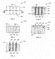
- FIG. 2 a top view of external surface 220 of component 200 is provided including a plurality of apertures 230 formed in external surface 220.
- FIG. 3 is a sectional view taken in direction 3-3 of FIG. 2 of component 200 including plurality of apertures 230 that are empty.
- External surface 220 can be prepared for coating by machining, grit-blasting, sanding, etching, or combinations thereof, to remove any old coatings or to prepare external surface 200 for coating.
- Plugs 250 substantially fill plurality of apertures 230.
- Plugs 250 can be substantially even with external surface 220 of component 200 or situated slightly above external surface 200 of component 200, as shown in FIG. 4 .
- Plugs 250 comprise a removable material.
- Removable material which forms plugs 250 is applied using, for example, but not limited to, a syringe, caulking-tube, or combination thereof.
- Removable material includes high temperature resistant filler materials, binding agents and combinations thereof.
- high temperature resistant filler materials are materials that generally withstand temperatures greater than about 315°C (about 600°F) or materials that withstand temperatures generally in the range of about 315°C (about 600°F) to about 982°C (about 1800°F).
- Removable material is selected from materials that are water soluble, magnetic, chemically dissolvable, or heat degradable.
- Suitable examples of removable material for plugs 250 include, but are not limited to, high temperature resistant filler materials, such as but not limited to, aluminum oxide (Al 2 O 3 ), zirconium oxide (ZrO 2 ), magnesium oxide (MgO), silicon dioxide (SiO 2 ), zircon (ZrSiO 4 ), tungsten carbide (WC), silicon carbide (SiC), silicon nitride, boron nitride, aluminum nitride, and graphite.
- high temperature resistant filler materials such as but not limited to, aluminum oxide (Al 2 O 3 ), zirconium oxide (ZrO 2 ), magnesium oxide (MgO), silicon dioxide (SiO 2 ), zircon (ZrSiO 4 ), tungsten carbide (WC), silicon carbide (SiC), silicon nitride, boron nitride, aluminum nitride, and graphite.
- removable material examples include binding agents, viscosity adjusters, and dispersants, such as, but not limited to, phosphates, silicates, sugar, high temperature salts, gum, resins, polyvinyl alcohol (PVA), polyethylene glycol, polymethyl methacrylate (PMMA), and combinations thereof.
- dispersants such as, but not limited to, phosphates, silicates, sugar, high temperature salts, gum, resins, polyvinyl alcohol (PVA), polyethylene glycol, polymethyl methacrylate (PMMA), and combinations thereof.
- a suitable example of a solvent for forming and shaping plug 250 includes water.
- Other suitable examples of solvents for forming and shaping plugs 250 include alcohol, acetone, terpineol.
- plugs 250 prior to drying, include about 50% to 80% by weight high temperature resistant filler material, about 10% to about 40% by weight binding agent, and about 5%-25% by weight water or alternatively about 55% to 75% by weight high temperature resistant filler material, about 15% to about 35% by weight binding agent, and about 8%-20% by weight water, or alternatively about 60% to 70% by weight high temperature resistant filler material, about 20% to about 30% by weight binding agent, and about 10%-15% by weight water.
- plugs 250 include only refectory material and binding agents.
- Plug 250 is dried using any suitable method, such as, but not limited to, air drying, heat, or chemicals to form the solid plug 250 in apertures 230 of component 200. After plug 250 is dried, external surface 220 of component is coated with least one coating. As shown in FIG. 5 , a first coating 260 is applied to external surface 220 of component 200 and a second coating 270 is applied to first coating 260. In one embodiment, first coating 260 is a bond coating.
- Suitable examples of bond coating include, but are not limited to, MCrAlX coatings, where M is cobalt, nickel, iron, or combinations thereof, X is an active element, such as yttrium (Y) and/or silicon (Si) and/or at least one rare earth element or hafnium (Hf).
- second coating 270 is a thermal barrier coating (TBC).
- TBCs include, but are not limited to, ceramic coatings, such as zirconium oxide (ZrO 2 ) the crystalline structure of which may be partially or completely stabilized by adding yttrium oxide (Y 2 O 3 ).
- First coating 260 and second coating 270 are applied at elevated temperatures, generally greater than about 400°C.
- Plug 250 withstands the high temperatures necessary for application of coatings. After coatings 260 and 270 are applied, component 200 is cooled.
- organics of plug 250 may be "burned" off depending on the temperature that surface 220 reaches during coatings processing. Examples of organics that are burned-off include carbon containing materials, and material containing sulfur that may be present in binding agents, surfactants, dispersants, wetting agents. Most organics, the burn off between 300°C - 800°C.
- component 200 including plug 250 can be immersed in a bath of water, until the plug 250 dissolves, leaving clear apertures 230 as shown in FIG. 6 .
- the water bath causes the plug 250 to dissolve in the water and frees apertures 230, leaving component 200 having coatings 260 and 270 thereon and apertures 230 free from any coating or other materials, without having to engage in hand drilling to clear apertures 230.
- an external force such as mechanical (e.g. pressurized water) or acoustical vibration (e.g. ultrasonics) may be employed in the water bath.
- a non-aqueous solvent bath is used to remove or dissolve plug 250.
- the non-aqueous solvent is selected to react with or dissolve the high temperature resistant filler material of plug 250.
- Suitable examples of non-aqueous or waterless solvents include, but are not limited to, alcohols (e.g., acetone), ammonia, weak acids, (e.g., such as citric acid), 5-10% HCl, nitric acid, sulfuric acid, perchloric acid, boric acid, or terpineol.
- removable material of plug 250 includes high temperature resistant filler materials and binders that are soluble in a non-aqueous solvent.
- plug 250 component 200 including plug 250 is immersed in a bath of the non-aqueous solvent.
- An example of removable material for plug 250 including high temperature resistant filler material and binders is, but is not limited to, an alumina filler mixed with polymethyl methacrylate (PMMA) in an acetone solvent using PMMA as binder.
- PMMA polymethyl methacrylate
- removable material of plug 250 includes an oxide filler.
- an acidic descaler is used to remove plug 250 including an oxide filler.
- acidic descalers include, but are not limited to, citric acid, hydrochloric acid, nitric acid, sulfuric acid, perchloric acid, or boric acid.
- plug 250 includes impure graphite powder which may be burned off at 400°C in air or in the presence of water.
- component 200 is heat treated at about 350-650°C, to degrade plug 250 including graphite powder for easy removal.
- plug 250 removal may also be accomplished by high pressure air spraying, acid cleaning, ultrasonic treatment in water, or a combination thereof.
- plug 250 is magnetic.
- the magnetic plug 250 includes magnetic oxide with a Curie Temperature of greater than about 600°C, and that magnetic oxide remains magnetic after the coating process.
- a suitable example of a magnetic oxide having a Curie Temperature of greater than 600°C includes, but is not limited to, of Iron Oxide (Fe 2 O 3 ), which has a Curie Temperature of 622°C.
- a magnet is used to remove plug 250 including magnetic oxide. During removal, magnet is placed adjacent to plug 250 including magnetic oxide material and magnet attracts plug 205 out of apertures 230, leaving a component 200 having a coating on the surface and clean apertures 230.
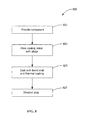
- FIG. 7 illustrates a method 700 of coating a component 200 (see FIGS. 4-6 ).
- Method 700 includes providing component 200, step 701 (see FIGS. 2-3 ).
- Method 700 includes masking at least one aperture 230 with plug 250, step 703 (see FIG. 4 ).
- Masking includes filling plurality of apertures 230 with plug 250 including removable material, wherein the removable material is initially in a paste form and applied using any suitable application means, such as, but not limited to, manual application, syringes, caulk-guns, and combinations thereof. Depending on the viscosity of the removable material, it may be dried using any suitable means, prior to application of coatings.
- Method 700 includes applying at least one coating 260, 270 to external surface 220 of component 200, step 705 (see FIG. 5 ).
- Method 700 includes eliminating plug 250 including removable material leaving open apertures 230 in external surface 220 of the coated component 200, step 707 (see FIG. 6 ).
- Step of eliminating, step 707 can include a process for breaking up, degrading, and dissolving removable material, such as by using water to dissolve removable material with or without the aid of external forces (e.g., pressure, acoustics, magnets, etc.), using chemical means, heat treating, magnetic means, or combinations thereof.
- apertures 230 can further be finished by drilling apertures 230 that are visible on coated component 200.
- FIG. 8 illustrates method 800 of forming at least one cooling hole 109 in a component 200 (see FIG. 1 ).
- apertures 230 can be cooling holes 109.
- Method 800 includes providing component 200 having external surface 220 and including a plurality of cooling holes 109, step 801 (see FIGS. 1-3 ).
- Method 800 includes masking at least one of plurality of cooling holes 109 with plug 250, plug 250 comprising a water soluble paste, step 803 (see FIG. 4 ).
- Suitable examples of water soluble paste include about 50% to 80% by weight refractory material and about 10% to about 40% by weight binding agent, and 5-25% water before water soluble paste has dried to form plug 250 (see FIG.
- Method 800 includes coating external surface 220 of component 200 with bond coat 260 and thermal barrier coating 270, step 805 (see FIG. 5 ).
- Method 800 includes dissolving plug 250 including water soluble paste in water leaving open cooling holes 109 in external surface 220 of coated component 200, step 807 (see FIG. 6 ).
- plug 250 comprises, prior to drying, 60g alumina flour, 25g 30% colloidal silica binder, and 15g water. This composition is formed into a desired plug shape and is applied manually onto aperture 230, a cooling hole opening on a surface of a gas turbine stage 1 nozzle.
- a High Velocity Oxygen Fuel (HVOF) Thermal Spray process is used to apply first coating 260, a bond coating, to surface 220 of component 200.
- second coating 270, a TBC is applied to first coating 260 using Air Plasma Spray (APS) process.
- component 200 is dipped into a bath containing warm water to dissolve plug 250, leaving a component 200 having a bond coat, a TBC and open apertures 230. After removing plugs 250 from apertures 230, final heat treatment is applied to component 200 to cure the applied bond coating and TBC.
- HVOF High Velocity Oxygen Fuel
- APS Air Plasma Spray
- plug 250 comprises a graphite paste.
- the graphite paste includes fine carbon powder dispersed in a solvent (aqueous or non-aqueous) and may include special additives for adjusting viscosity, preventing adhesion to cooling holes, and preventing corrosion.
- Graphite paste is applied manually into apertures 230, or cooling hole openings, on surface 220 of component 200, a gas turbine stage 1 nozzle.
- a HVOF Thermal Spray process is used to apply first coating 260, a bond coating to surface 220 of component 200.
- second coating 270, a TBC is applied to first coating 260 using an APS process.
- Component 200 including plug 250 is heated in an air furnace to about 538°C (about 1000°F) to oxidize/burn off plug 250 including graphite in apertures 230. After burn-off any remaining bits or pieces of plug 250 in apertures 230 is air blasted to remove the remnant powder. After removing plugs 250 from apertures 230, final heat treatment is applied to the component 200 to cure the applied bond coating and TBC.
- plug 250 comprises a mixture of acetone, polymethyl methacrylate (PMMA), and alumina.
- PMMA polymethyl methacrylate
- 20 wt% PMMA is dissolved in acetone, then alumina is added to maximize the solids content to form a paste.
- the paste is applied to apertures 230, or in the cooling hole openings on a surface 220 of component 200, a gas turbine stage 1 nozzle.
- the paste is dried forming plugs 250 in apertures 230.
- a HVOF Thermal Spray process is used to apply first coating 260, a bond coating to surface 220 of component 200.
- second coating 270, a TBC is applied to first coating 260 using an APS process.
- component 200 After applying first coating 260 and second coating 270, component 200 is dipped into an acetone tank to dissolve PMMA in plug 250. Acetone dissolves plug 250 leaving open apertures 230. Alternatively, ultrasonication may be used in combination with the acetone bath to remove plug 250 from apertures 230. After removing plugs 250 from apertures 230, final heat treatment is applied to the component 200 to cure the applied bond coating and TBC.
Landscapes
- Engineering & Computer Science (AREA)
- Chemical & Material Sciences (AREA)
- Mechanical Engineering (AREA)
- Materials Engineering (AREA)
- Plasma & Fusion (AREA)
- Chemical Kinetics & Catalysis (AREA)
- Physics & Mathematics (AREA)
- Metallurgy (AREA)
- Organic Chemistry (AREA)
- General Engineering & Computer Science (AREA)
- Turbine Rotor Nozzle Sealing (AREA)
- Other Surface Treatments For Metallic Materials (AREA)
- Application Of Or Painting With Fluid Materials (AREA)
Abstract
Description
- The present invention relates generally to a method of coating a component, a method of forming cooling holes, and a water soluble aperture plug.
- When turbines are used on aircraft or for power generation, they are typically run at a temperature as high as possible, for maximum operating efficiency. Since high temperatures can damage the alloys used for the components, a variety of approaches have been used to raise the operating temperature of the metal components. One approach calls for the incorporation of internal cooling channels in the component, through which cool air is forced during engine operation. The cooling holes can be formed in the substrate by specialized laser-drilling techniques. Cooling air (usually provided by the engine's compressor) is fed through the holes from the cooler side to the hot side of the combustor wall. As long as the holes remain clear, the rushing air will assist in lowering the temperature of the hot metal surface and preventing melting or other degradation of the component.
- Another technique for protecting the metal parts and effectively raising the practical operating temperature of an aircraft engine involves the use of a thermal barrier coating (TBC). The TBC is usually ceramic-based. TBC systems frequently also include a bond coat which is placed between the ceramic coating and the substrate to improve adhesion. The use of TBC's in conjunction with the battery of cooling holes is sometimes the most effective means for protecting an engine part. However, incorporation of both systems can be very difficult. For example, the cooling holes sometimes cannot be formed in the engine part after a TBC has been applied, since lasers usually cannot effectively penetrate both the ceramic material and the metal to form the pattern of holes. If the cooling holes are formed prior to the application of the TBC system, they may become covered and at least partially obstructed when the bond coat and/or TBC is applied. Complete removal of the ceramic-metal material from the holes can be very time-consuming and ineffective, if not impossible. Any obstruction of the holes during engine operation can interfere with the passage of cooling air, can waste compressor power, and can possibly lead to engine component damage due to overheating.
- Therefore a component and methods of coating the component and method of making cooling holes in the component that do not suffer from the above drawbacks are desirable in the art.
- According to an exemplary embodiment of the present disclosure, a method of coating a component is provided. The method includes providing the component having a surface and including a plurality of apertures formed therein. The method includes masking at least one of the plurality of apertures with a plug, the plug comprising a removable material. The method includes applying at least one coating to the surface of the component. The method includes eliminating the removable material leaving open apertures in the surface of the coated component.
- According to another exemplary embodiment of the present disclosure, a method of forming at least one cooling hole in a component is provided. The method includes providing the component having a surface and including plurality of cooling holes therein. The method includes masking at least one of the plurality of cooling holes with a plug, the plug comprising a water soluble paste. The method includes coating the surface of the component with a bond coat and thermal barrier coating. The method includes dissolving the plug including water soluble paste in water leaving open cooling holes in the surface of the coated component.
- According to another exemplary embodiment of the present disclosure, a water-soluble aperture plug is provided. The water-soluble aperture plug includes water soluble high temperature resistant filler material including aluminum oxide (Al2O3), zirconium oxide (ZrO2), magnesium oxide (MgO), silicon dioxide (SiO2), zircon (ZrSiO4), graphite, tungsten carbide (WC), silicon carbide (SiC), silicon nitride, boron nitride, aluminum nitride and binding agents and dispersants including phosphates, silicates, sugar, salt, gum, resin, polyvinyl alcohol (PVA), polyethylene glycol, and combinations thereof.
- Other features and advantages of the present invention will be apparent from the following more detailed description of the preferred embodiment, taken in conjunction with the accompanying drawings which illustrate, by way of example, the principles of the invention.
-
FIG. 1 is a perspective view of a component of the present disclosure. -
FIG. 2 is a schematic top view of a component ofFIG. 1 having a plurality of apertures formed therein of the present disclosure. -
FIG. 3 is a sectional view taken in direction 3-3 ofFIG. 2 of the component including the plurality of apertures. -
FIG. 4 is a schematic view of the plurality of apertures each filled with a plug according to the present disclosure. -
FIG. 5 is a schematic view of applying a plurality of layers to the component according to the present disclosure. -
FIG. 6 is a schematic view of the plurality of apertures an exemplary alternative embodiment of at least one dissimilar metallic layer coated on a component of the present disclosure. -
FIG. 7 is a flow chart of an exemplary method of making a component of the present disclosure. -
FIG. 8 is a flow chart of an alternative exemplary method of forming cooling holes in a component of the present disclosure. - Wherever possible, the same reference numbers will be used throughout the drawings to represent the same parts.
- Provided is a method of coating a component, method of forming at least one cooling hole in the component and a plug for use with the methods. More specifically, the plug includes water soluble binder material and high temperature resistant filler materials including aluminum oxide (Al2O3), zirconium oxide (ZrO2), magnesium oxide (MgO), silicon dioxide (SiO2), zircon (ZrSiO4), graphite, tungsten carbide (WC), silicon carbide (SiC), silicon nitride, boron nitride, aluminum nitride and binding agents and dispersants including phosphates, silicates, sugar, salt, gum, resin, polyvinyl alcohol (PVA), polyethylene glycol, and combinations thereof.
- One advantage of an embodiment of the present disclosure includes maintaining original shape and dimension of apertures or cooling holes in components. Another advantage of an embodiment is better control of airflow for recoated components. Yet another advantage is faster processing of recoated components. Another advantage of an embodiment is decreased time for cleaning of cooling holes after components are coated or recoated. Yet another advantage of an embodiment is significant labor savings because no drilling is required to clear cooling holes after coating. Yet another advantage is having a high temperature resistant masking material.
- Components of the present disclosure can be used in any applications that undergo temperature changes, such as, but not limited to, power generation systems which include, but are not limited to, gas turbines, steam turbines, jet turbines, and other turbine assemblies.
-
FIG. 1 is a perspective view ofturbine blade 100 that can be used with the method of the present disclosure.Turbine blade 100 has three sections: an airfoil section 103, aplatform section 105, and adovetail section 107. Airfoil section 103 includes a plurality ofcooling holes 109 which permit cooling air to exhaust from an interior space ofturbine blade 100.Turbine blade 100 is typically fabricated from a high temperature oxidation and corrosion resistant alloy with high temperature strength, such as a nickel-based superalloy. The exterior surface of airfoil section 103 of theturbine blade 100 may be coated with any coating system known in the art for coating on aturbine blade 100 opposed to combustion gases. A known coating system includes a bond coat on the surface of theturbine blade 100, typically comprising an aluminide or MCrAlY (where M=Ni, Co, and/or Fe) and a thermal barrier layer disposed on the bond coating, which may include ceramic materials, such as yttria stabilized zirconia. The thermal barrier coating is typically applied by a process, such as air plasma spray or electron beam physical vapor deposition, that provides the surface with a coating morphology suitable for providing airfoil section 103 surface with resistance to heat. The combination of the bond coating and thermal barrier layer provide airfoil section 103 with long-term resistance to heat and corrosion resulting from contact with the combustion gas stream. - The present disclosure relates to a process of masking
cooling holes 109 or apertures 230 of acomponent 200 before the deposition of a coating material onexternal surface 220 ofcomponent 200. As shown inFIG. 1 , component can be aturbine blade 100. Other examples ofcomponents 200, include but are not limited to, component havingcooling hole 109 orapertures 230, such as, but not limited to, nozzles, vanes, shrouds, buckets, transition pieces and liners, and combinations thereof. - As shown in
FIG. 2 , a top view ofexternal surface 220 ofcomponent 200 is provided including a plurality ofapertures 230 formed inexternal surface 220.FIG. 3 is a sectional view taken in direction 3-3 ofFIG. 2 ofcomponent 200 including plurality ofapertures 230 that are empty.External surface 220 can be prepared for coating by machining, grit-blasting, sanding, etching, or combinations thereof, to remove any old coatings or to prepareexternal surface 200 for coating. - As shown in
FIG. 4 , plurality ofapertures 230 are filled with or masked byplugs 250.Plugs 250 substantially fill plurality ofapertures 230.Plugs 250 can be substantially even withexternal surface 220 ofcomponent 200 or situated slightly aboveexternal surface 200 ofcomponent 200, as shown inFIG. 4 .Plugs 250 comprise a removable material. Removable material which forms plugs 250 is applied using, for example, but not limited to, a syringe, caulking-tube, or combination thereof. Removable material includes high temperature resistant filler materials, binding agents and combinations thereof. As used herein "high temperature resistant filler materials" are materials that generally withstand temperatures greater than about 315°C (about 600°F) or materials that withstand temperatures generally in the range of about 315°C (about 600°F) to about 982°C (about 1800°F). Removable material is selected from materials that are water soluble, magnetic, chemically dissolvable, or heat degradable. Suitable examples of removable material forplugs 250 include, but are not limited to, high temperature resistant filler materials, such as but not limited to, aluminum oxide (Al2O3), zirconium oxide (ZrO2), magnesium oxide (MgO), silicon dioxide (SiO2), zircon (ZrSiO4), tungsten carbide (WC), silicon carbide (SiC), silicon nitride, boron nitride, aluminum nitride, and graphite. Suitable examples of removable material include binding agents, viscosity adjusters, and dispersants, such as, but not limited to, phosphates, silicates, sugar, high temperature salts, gum, resins, polyvinyl alcohol (PVA), polyethylene glycol, polymethyl methacrylate (PMMA), and combinations thereof. - A suitable example of a solvent for forming and shaping
plug 250 includes water. Other suitable examples of solvents for forming and shapingplugs 250 include alcohol, acetone, terpineol. In one embodiment, plugs 250, prior to drying, include about 50% to 80% by weight high temperature resistant filler material, about 10% to about 40% by weight binding agent, and about 5%-25% by weight water or alternatively about 55% to 75% by weight high temperature resistant filler material, about 15% to about 35% by weight binding agent, and about 8%-20% by weight water, or alternatively about 60% to 70% by weight high temperature resistant filler material, about 20% to about 30% by weight binding agent, and about 10%-15% by weight water. After drying, plugs 250 include only refectory material and binding agents. -
Plug 250 is dried using any suitable method, such as, but not limited to, air drying, heat, or chemicals to form thesolid plug 250 inapertures 230 ofcomponent 200. Afterplug 250 is dried,external surface 220 of component is coated with least one coating. As shown inFIG. 5 , afirst coating 260 is applied toexternal surface 220 ofcomponent 200 and asecond coating 270 is applied tofirst coating 260. In one embodiment,first coating 260 is a bond coating. Suitable examples of bond coating, include, but are not limited to, MCrAlX coatings, where M is cobalt, nickel, iron, or combinations thereof, X is an active element, such as yttrium (Y) and/or silicon (Si) and/or at least one rare earth element or hafnium (Hf). In one embodiment,second coating 270 is a thermal barrier coating (TBC). Suitable examples of TBCs, include, but are not limited to, ceramic coatings, such as zirconium oxide (ZrO2) the crystalline structure of which may be partially or completely stabilized by adding yttrium oxide (Y2O3). -
First coating 260 andsecond coating 270 are applied at elevated temperatures, generally greater than about 400°C. Plug 250 withstands the high temperatures necessary for application of coatings. Aftercoatings component 200 is cooled. During application ofcoatings plug 250 may be "burned" off depending on the temperature that surface 220 reaches during coatings processing. Examples of organics that are burned-off include carbon containing materials, and material containing sulfur that may be present in binding agents, surfactants, dispersants, wetting agents. Most organics, the burn off between 300°C - 800°C. To removeplug 250, depending on the composition of removable material ofplug 250,component 200, includingplug 250 can be immersed in a bath of water, until theplug 250 dissolves, leavingclear apertures 230 as shown inFIG. 6 . The water bath causes theplug 250 to dissolve in the water and freesapertures 230, leavingcomponent 200 havingcoatings apertures 230 free from any coating or other materials, without having to engage in hand drilling toclear apertures 230. To aid the plug removal process, an external force such as mechanical (e.g. pressurized water) or acoustical vibration (e.g. ultrasonics) may be employed in the water bath. - In another embodiment, a non-aqueous solvent bath is used to remove or dissolve
plug 250. The non-aqueous solvent is selected to react with or dissolve the high temperature resistant filler material ofplug 250. Suitable examples of non-aqueous or waterless solvents, include, but are not limited to, alcohols (e.g., acetone), ammonia, weak acids, (e.g., such as citric acid), 5-10% HCl, nitric acid, sulfuric acid, perchloric acid, boric acid, or terpineol. In one embodiment, removable material ofplug 250 includes high temperature resistant filler materials and binders that are soluble in a non-aqueous solvent. To removeplug 250component 200 includingplug 250 is immersed in a bath of the non-aqueous solvent. An example of removable material forplug 250 including high temperature resistant filler material and binders is, but is not limited to, an alumina filler mixed with polymethyl methacrylate (PMMA) in an acetone solvent using PMMA as binder. - In yet another embodiment, removable material of
plug 250 includes an oxide filler. To removeplug 250 including an oxide filler, an acidic descaler is used. Suitable examples of acidic descalers include, but are not limited to, citric acid, hydrochloric acid, nitric acid, sulfuric acid, perchloric acid, or boric acid. - In another embodiment, plug 250 includes impure graphite powder which may be burned off at 400°C in air or in the presence of water. To remove
plug 250 including graphite powder,component 200 is heat treated at about 350-650°C, to degrade plug 250 including graphite powder for easy removal. In an alternative embodiment, plug 250 removal may also be accomplished by high pressure air spraying, acid cleaning, ultrasonic treatment in water, or a combination thereof. - In another embodiment, plug 250 is magnetic. For high temperature coating processes such as High Velocity Oxygen Fuel (HVOF) or Air Plasma Spray (APS), the
magnetic plug 250 includes magnetic oxide with a Curie Temperature of greater than about 600°C, and that magnetic oxide remains magnetic after the coating process. A suitable example of a magnetic oxide having a Curie Temperature of greater than 600°C, includes, but is not limited to, of Iron Oxide (Fe2O3), which has a Curie Temperature of 622°C. A magnet is used to removeplug 250 including magnetic oxide. During removal, magnet is placed adjacent to plug 250 including magnetic oxide material and magnet attracts plug 205 out ofapertures 230, leaving acomponent 200 having a coating on the surface andclean apertures 230. -
FIG. 7 illustrates amethod 700 of coating a component 200 (seeFIGS. 4-6 ).Method 700 includes providingcomponent 200, step 701 (seeFIGS. 2-3 ).Method 700 includes masking at least oneaperture 230 withplug 250, step 703 (seeFIG. 4 ). Masking includes filling plurality ofapertures 230 withplug 250 including removable material, wherein the removable material is initially in a paste form and applied using any suitable application means, such as, but not limited to, manual application, syringes, caulk-guns, and combinations thereof. Depending on the viscosity of the removable material, it may be dried using any suitable means, prior to application of coatings.Method 700 includes applying at least onecoating external surface 220 ofcomponent 200, step 705 (seeFIG. 5 ).Method 700 includes eliminatingplug 250 including removable material leavingopen apertures 230 inexternal surface 220 of thecoated component 200, step 707 (seeFIG. 6 ). Step of eliminating,step 707, can include a process for breaking up, degrading, and dissolving removable material, such as by using water to dissolve removable material with or without the aid of external forces (e.g., pressure, acoustics, magnets, etc.), using chemical means, heat treating, magnetic means, or combinations thereof. After the step of eliminating,step 707,apertures 230 can further be finished by drillingapertures 230 that are visible oncoated component 200. -
FIG. 8 illustratesmethod 800 of forming at least onecooling hole 109 in a component 200 (seeFIG. 1 ). As shown inFIGS. 1-6 ,apertures 230 can be cooling holes 109.Method 800 includes providingcomponent 200 havingexternal surface 220 and including a plurality ofcooling holes 109, step 801 (seeFIGS. 1-3 ).Method 800 includes masking at least one of plurality ofcooling holes 109 withplug 250, plug 250 comprising a water soluble paste, step 803 (seeFIG. 4 ). Suitable examples of water soluble paste include about 50% to 80% by weight refractory material and about 10% to about 40% by weight binding agent, and 5-25% water before water soluble paste has dried to form plug 250 (seeFIG. 4 )Method 800 includes coatingexternal surface 220 ofcomponent 200 withbond coat 260 andthermal barrier coating 270, step 805 (seeFIG. 5 ).Method 800 includes dissolvingplug 250 including water soluble paste in water leaving open cooling holes 109 inexternal surface 220 ofcoated component 200, step 807 (seeFIG. 6 ). - The following examples are intended to further illustrate the present disclosure. They are not intended to limit the disclosure in any way.
- Example 1: In one embodiment, plug 250 comprises, prior to drying, 60g alumina flour, 25g 30% colloidal silica binder, and 15g water. This composition is formed into a desired plug shape and is applied manually onto
aperture 230, a cooling hole opening on a surface of a gas turbine stage 1 nozzle. A High Velocity Oxygen Fuel (HVOF) Thermal Spray process is used to applyfirst coating 260, a bond coating, to surface 220 ofcomponent 200. Next,second coating 270, a TBC, is applied tofirst coating 260 using Air Plasma Spray (APS) process. Next,component 200 is dipped into a bath containing warm water to dissolveplug 250, leaving acomponent 200 having a bond coat, a TBC andopen apertures 230. After removingplugs 250 fromapertures 230, final heat treatment is applied tocomponent 200 to cure the applied bond coating and TBC. - Example 2: In another embodiment, plug 250 comprises a graphite paste. The graphite paste includes fine carbon powder dispersed in a solvent (aqueous or non-aqueous) and may include special additives for adjusting viscosity, preventing adhesion to cooling holes, and preventing corrosion. Graphite paste is applied manually into
apertures 230, or cooling hole openings, onsurface 220 ofcomponent 200, a gas turbine stage 1 nozzle. A HVOF Thermal Spray process is used to applyfirst coating 260, a bond coating to surface 220 ofcomponent 200. Next,second coating 270, a TBC, is applied tofirst coating 260 using an APS process.Component 200 includingplug 250 is heated in an air furnace to about 538°C (about 1000°F) to oxidize/burn offplug 250 including graphite inapertures 230. After burn-off any remaining bits or pieces ofplug 250 inapertures 230 is air blasted to remove the remnant powder. After removingplugs 250 fromapertures 230, final heat treatment is applied to thecomponent 200 to cure the applied bond coating and TBC. - Example 3: In another embodiment, plug 250 comprises a mixture of acetone, polymethyl methacrylate (PMMA), and alumina. In making
plug 250, 20 wt% PMMA is dissolved in acetone, then alumina is added to maximize the solids content to form a paste. The paste is applied toapertures 230, or in the cooling hole openings on asurface 220 ofcomponent 200, a gas turbine stage 1 nozzle. The paste is dried formingplugs 250 inapertures 230. A HVOF Thermal Spray process is used to applyfirst coating 260, a bond coating to surface 220 ofcomponent 200. Next,second coating 270, a TBC, is applied tofirst coating 260 using an APS process. After applyingfirst coating 260 andsecond coating 270,component 200 is dipped into an acetone tank to dissolve PMMA inplug 250. Acetone dissolves plug 250 leavingopen apertures 230. Alternatively, ultrasonication may be used in combination with the acetone bath to removeplug 250 fromapertures 230. After removingplugs 250 fromapertures 230, final heat treatment is applied to thecomponent 200 to cure the applied bond coating and TBC. - While the invention has been described with reference to a preferred embodiment, it will be understood by those skilled in the art that various changes may be made and equivalents may be substituted for elements thereof without departing from the scope of the invention. In addition, many modifications may be made to adapt a particular situation or material to the teachings of the invention without departing from the essential scope thereof. Therefore, it is intended that the invention not be limited to the particular embodiment disclosed as the best mode contemplated for carrying out this invention, but that the invention will include all embodiments falling within the scope of the appended claims.
- Various aspects and embodiments of the present invention are defined by the following numbered clauses:
- 1. A method of coating a component comprising:
- providing the component having a surface and including a plurality of apertures formed therein;
- masking at least one of the plurality of apertures with a plug, the plug comprising a removable material;
- applying at least one coating to the surface of the component; and
- eliminating the plug including removable material leaving open apertures in the surface of the coated component.
- 2. The method of clause 1, wherein the method includes, prior to the step of masking, preparing the component by machining, grit-blasting, sanding, etching, or combinations thereof.
- 3. The method of any preceding clause, wherein the method includes, prior to the step of applying the at least one coating of drying the removable material.
- 4. The method of any preceding clause, wherein the removable material of the plug comprises at least one high temperature resistant filler material, at least one binding agent, and combinations thereof.
- 5. The method of any preceding clause, wherein the removable material is water soluble, chemically dissolvable, magnetic, heat degradable, and combinations thereof.
- 6. The method of any preceding clause, wherein the at least one high temperature resistant filler material includes aluminum oxide (Al2O3), zirconium oxide (ZrO2), silicon dioxide(SiO2), zircon (ZrSiO4), graphite, and the at least one binding agent includes phosphate, silicates, sugar, gum, resin, polyvinyl alcohol (PVA), and combinations thereof.
- 7. The method of any preceding clause, wherein the plug, prior to drying, comprises about 50% to 80% by weight of at least one high temperature resistant filler material, and about 10% to about 40% by weight of at least one binding agent, and about 5 % to about 25% by weight water.
- 8. The method of any preceding clause, wherein the plug is water soluble, magnetic, heat degradable, chemically dissolvable, and combinations thereof.
- 9. The method of any preceding clause, wherein the component is a nozzle, a blade, a vane, a shroud, a bucket, a transition piece, a liner and combinations thereof.
- 10. The method of any preceding clause, wherein the step of applying at least one coating includes applying a first coating at a first temperature and applying a second coating at a second temperature.
- 11. The method of any preceding clause, wherein the first coating is a bond coating and the second coating is a thermal barrier coating.
- 12. The method of any preceding clause, wherein after the step of eliminating the plug, apertures are finished using a drill.
- 13. A method of forming at least one cooling hole in a component comprising:
- providing the component having a surface and including plurality of cooling holes therein;
- masking at least one of the plurality of cooling holes with a plug, the plug comprising a water soluble paste;
- coating the surface of the component with a bond coat and thermal barrier coating; and
- dissolving the plug including water soluble paste in water leaving open cooling holes in the surface of the coated component.
- 14. The method of any preceding clause, wherein the method includes, prior to the step of applying the water soluble paste, of preparing the component by machining, grit-blasting, sanding, etching, or combinations thereof.
- 15. The method of any preceding clause, wherein the component is a nozzle, a blade, a vane, a shroud, a bucket, a transition piece, a liner, and combinations thereof.
- 16. The method of any preceding clause, wherein the water soluble paste comprises high temperature resistant filler materials, binding agents, and combinations thereof.
- 17. The method of any preceding clause, wherein water soluble paste, prior to drying, comprises about 50% to 80% by weight high temperature resistant filler materials, about 10% to about 40% by weight binder, and about 5% to about 25% by weight water.
- 18. The method of any preceding clause, including an additional step of, prior to the step of applying the bond coat, drying the water soluble paste.
- 19. The method of any preceding clause, wherein the water soluble paste is applied using a syringe, caulking-tube, brush, or combination thereof.
- 20. A water-soluble aperture plug comprising:
- water soluble high temperature resistant filler materials including aluminum oxide (Al2O3), zirconium oxide (ZrO2), magnesium oxide (MgO), silicon dioxide (SiO2), zircon (ZrSiO4), graphite, tungsten carbide (WC), silicon carbide (SiC), silicon nitride, boron nitride, aluminum nitrides; and
- binding agents and dispersants including phosphates, silicates, sugar, salt, gum, resin, polyvinyl alcohol (PVA), polyethylene glycol, and combinations thereof.
Claims (15)
- A method of coating a component comprising:providing the component (200) having a surface and including a plurality of apertures formed therein;masking at least one of the plurality of apertures with a plug (250), the plug comprising a removable material;applying at least one coating (260, 270) to the surface of the component (200); andeliminating the plug (250) including removable material leaving open apertures (230) in the surface of the coated component.
- The method of claim 1, wherein the method includes, prior to the step of masking, preparing the component by machining, grit-blasting, sanding, etching, or combinations thereof.
- The method of claim 1 or claim 2, wherein the method includes, prior to the step of applying the at least one coating of drying the removable material.
- The method of claim 1, 2 or 3, wherein the removable material of the plug (250) comprises at least one high temperature resistant filler material, at least one binding agent, and combinations thereof.
- The method of claim 4, wherein the removable material is water soluble, chemically dissolvable, magnetic, heat degradable, and combinations thereof.
- The method of claim 4 or claim 5, wherein the at least one high temperature resistant filler material includes aluminum oxide (Al2O3), zirconium oxide (ZrO2), silicon dioxide(SiO2), zircon (ZrSiO4), graphite, and the at least one binding agent includes phosphate, silicates, sugar, gum, resin, polyvinyl alcohol (PVA), and combinations thereof.
- The method of any preceding claim, wherein the plug (250), prior to drying, comprises about 50% to 80% by weight of at least one high temperature resistant filler material, and about 10% to about 40% by weight of at least one binding agent, and about 5 % to about 25% by weight water.
- The method of any preceding claim, wherein the plug (250) is water soluble, magnetic, heat degradable, chemically dissolvable, and combinations thereof.
- The method of any preceding claim, wherein the component (200) is a nozzle, a blade, a vane, a shroud, a bucket, a transition piece, a liner and combinations thereof.
- The method of any preceding claim, wherein the step of applying at least one coating (260, 270) includes applying a first coating at a first temperature and applying a second coating at a second temperature.
- The method of claim 9, wherein the first coating is a bond coating and the second coating is a thermal barrier coating.
- The method of any preceding claim, wherein after the step of eliminating the plug, apertures are finished using a drill.
- A method of forming at least one cooling hole in a component comprising:providing the component (200) having a surface and including plurality of cooling holes therein;masking at least one of the plurality of cooling holes with a plug (250), the plug comprising a water soluble paste;coating the surface of the component with a bond coat and thermal barrier coating; anddissolving the plug (250) including water soluble paste in water leaving open cooling holes in the surface of the coated component.
- The method of claim 13, wherein the method includes, prior to the step of applying the water soluble paste, of preparing the component (200) by machining, grit-blasting, sanding, etching, or combinations thereof.
- A water-soluble aperture plug (250) comprising:water soluble high temperature resistant filler materials including aluminum oxide (Al2O3), zirconium oxide (ZrO2), magnesium oxide (MgO), silicon dioxide (SiO2), zircon (ZrSiO4), graphite, tungsten carbide (WC), silicon carbide (SiC), silicon nitride, boron nitride, aluminum nitrides; andbinding agents and dispersants including phosphates, silicates, sugar, salt, gum, resin, polyvinyl alcohol (PVA), polyethylene glycol, and combinations thereof.
Applications Claiming Priority (1)
| Application Number | Priority Date | Filing Date | Title |
|---|---|---|---|
| US13/469,478 US9518317B2 (en) | 2012-05-11 | 2012-05-11 | Method of coating a component, method of forming cooling holes and a water soluble aperture plug |
Publications (2)
| Publication Number | Publication Date |
|---|---|
| EP2662469A2 true EP2662469A2 (en) | 2013-11-13 |
| EP2662469A3 EP2662469A3 (en) | 2015-06-17 |
Family
ID=48366219
Family Applications (1)
| Application Number | Title | Priority Date | Filing Date |
|---|---|---|---|
| EP13167382.4A Withdrawn EP2662469A3 (en) | 2012-05-11 | 2013-05-10 | Method of coating a component, method of forming cooling holes, and a water soluble aperture plug |
Country Status (3)
| Country | Link |
|---|---|
| US (1) | US9518317B2 (en) |
| EP (1) | EP2662469A3 (en) |
| CN (1) | CN103388118B (en) |
Cited By (9)
| Publication number | Priority date | Publication date | Assignee | Title |
|---|---|---|---|---|
| EP2881489A1 (en) * | 2013-12-05 | 2015-06-10 | General Electric Company | Coating methods and a template for use with the coating methods |
| EP3100819A1 (en) * | 2015-06-03 | 2016-12-07 | United Technologies Corporation | Repair or remanufacture of cooled components with an oxidation resistant braze |
| EP3156513A1 (en) * | 2015-10-12 | 2017-04-19 | General Electric Company | Method of coating an article, water soluble plug for preventing hole blockage during coating |
| WO2018057414A1 (en) * | 2016-09-23 | 2018-03-29 | General Electric Company | Method of coating an article, paste and plug for preventing hole blockage during coating |
| EP3385404A1 (en) * | 2017-04-05 | 2018-10-10 | United Technologies Corporation | Method of manufacturing conductive film holes |
| WO2019074514A1 (en) * | 2017-10-13 | 2019-04-18 | General Electric Company | Coated components having adaptive cooling openings and methods of making the same |
| WO2021030249A1 (en) * | 2019-08-13 | 2021-02-18 | General Electric Company | Protective shields for improved coating of turbine component cooling features |
| US11634365B2 (en) | 2019-12-20 | 2023-04-25 | Richter Precision, Inc. | Low temperature carbon/bn/aluminum oxide coating |
| CN119910128A (en) * | 2025-04-03 | 2025-05-02 | 成都航宇超合金技术有限公司 | Integrated casting method of hollow turbine blades with air film holes |
Families Citing this family (24)
| Publication number | Priority date | Publication date | Assignee | Title |
|---|---|---|---|---|
| US9551058B2 (en) * | 2013-12-06 | 2017-01-24 | General Electric Company | Coating methods and a coated substrate |
| US20160089692A1 (en) * | 2014-09-30 | 2016-03-31 | General Electric Company | Turbine component coating processes and turbine components |
| WO2016077071A2 (en) * | 2014-11-11 | 2016-05-19 | Sikorsky Aircraft Corporation | Masking plug for cold spray repair at counterbore hole |
| US20150079288A1 (en) * | 2014-11-25 | 2015-03-19 | Caterpillar Inc. | Plug assembly for masking threaded holes |
| JP6235449B2 (en) | 2014-12-03 | 2017-11-22 | 三菱日立パワーシステムズ株式会社 | Thermal spray coating method, turbine high-temperature component, turbine, thermal spray coating masking pin, and masking member |
| CN105063544A (en) * | 2015-08-13 | 2015-11-18 | 马鞍山蓝科再制造技术有限公司 | Nano-particle electromagnetic interference prevention thermal barrier coating and manufacture method thereof |
| CN105063543A (en) * | 2015-08-13 | 2015-11-18 | 马鞍山蓝科再制造技术有限公司 | Inflaming retarding and oxidation resistance thermal barrier coating and manufacturing method thereof |
| CN105088126A (en) * | 2015-08-13 | 2015-11-25 | 马鞍山蓝科再制造技术有限公司 | Anti-thermal-shock thermal barrier coating with low thermal conductivity and preparation method thereof |
| US10030305B2 (en) | 2015-11-19 | 2018-07-24 | General Electric Company | Method to protect features during repair cycle |
| CN105507998A (en) * | 2015-12-31 | 2016-04-20 | 重庆隆鑫机车有限公司 | Painted structural assembly for silencer |
| CN105970139B (en) * | 2016-07-12 | 2018-04-24 | 华能国际电力股份有限公司 | Titration hole sealing device and method in micropores in thermal spraying process |
| CN108393648A (en) * | 2017-02-08 | 2018-08-14 | 通用电气公司 | Prevent the plug in solder access aperture from blocking up material and its method |
| US10272461B2 (en) | 2017-04-04 | 2019-04-30 | General Electric Company | Method for masking cooling passages |
| US10888892B2 (en) | 2018-08-23 | 2021-01-12 | General Electric Company | Protecting hole in component during coating process using plug with water soluble layer |
| US11603769B2 (en) | 2021-08-13 | 2023-03-14 | Raytheon Technologies Corporation | Forming lined cooling aperture(s) in a turbine engine component |
| US11813706B2 (en) | 2021-08-13 | 2023-11-14 | Rtx Corporation | Methods for forming cooling apertures in a turbine engine component |
| US11542831B1 (en) | 2021-08-13 | 2023-01-03 | Raytheon Technologies Corporation | Energy beam positioning during formation of a cooling aperture |
| US11732590B2 (en) | 2021-08-13 | 2023-08-22 | Raytheon Technologies Corporation | Transition section for accommodating mismatch between other sections of a cooling aperture in a turbine engine component |
| US11913119B2 (en) | 2021-08-13 | 2024-02-27 | Rtx Corporation | Forming cooling aperture(s) in a turbine engine component |
| US11898465B2 (en) | 2021-08-13 | 2024-02-13 | Rtx Corporation | Forming lined cooling aperture(s) in a turbine engine component |
| US12123839B2 (en) | 2021-08-13 | 2024-10-22 | Rtx Corporation | Forming and/or inspecting cooling aperture(s) in a turbine engine component |
| US11673200B2 (en) | 2021-08-13 | 2023-06-13 | Raytheon Technologies Corporation | Forming cooling aperture(s) using electrical discharge machining |
| CN114990468A (en) * | 2022-06-08 | 2022-09-02 | 哈尔滨汽轮机厂有限责任公司 | Preparation method of gas turbine combustor transition section thermal barrier coating for protecting gas film divergence hole |
| CN115008262A (en) * | 2022-06-29 | 2022-09-06 | 中国航发动力股份有限公司 | Hole blocking prevention method and hole blocking prevention agent for machining of parts with holes |
Family Cites Families (23)
| Publication number | Priority date | Publication date | Assignee | Title |
|---|---|---|---|---|
| JP2514173B2 (en) * | 1986-06-09 | 1996-07-10 | 名古屋油化株式会社 | Anti-corrosion, anti-noise and anti-vibration treatment method for under floor of automobile |
| US4743462A (en) | 1986-07-14 | 1988-05-10 | United Technologies Corporation | Method for preventing closure of cooling holes in hollow, air cooled turbine engine components during application of a plasma spray coating |
| US5413871A (en) * | 1993-02-25 | 1995-05-09 | General Electric Company | Thermal barrier coating system for titanium aluminides |
| US5902647A (en) | 1996-12-03 | 1999-05-11 | General Electric Company | Method for protecting passage holes in a metal-based substrate from becoming obstructed, and related compositions |
| US6024787A (en) | 1998-06-05 | 2000-02-15 | Industrial Technology Research Institute | Water soluble ceramic core for use in die casting, gravity and investment casting of aluminum alloys |
| US6321449B2 (en) | 1998-11-12 | 2001-11-27 | General Electric Company | Method of forming hollow channels within a component |
| WO2000048846A1 (en) * | 1999-02-19 | 2000-08-24 | Mitsubishi Pencil Kabushikikaisha | Method of manufacturing a pipe type ball-point pen tip |
| US6224673B1 (en) | 1999-08-11 | 2001-05-01 | General Electric Company | Apparatus for masking turbine components during vapor phase diffusion coating |
| US6234755B1 (en) * | 1999-10-04 | 2001-05-22 | General Electric Company | Method for improving the cooling effectiveness of a gaseous coolant stream, and related articles of manufacture |
| EP1373420B1 (en) * | 2001-03-05 | 2005-11-30 | Georg Gros | Water-based coating mixture, method for application of corrosion protection layer with said mixture, substrates coated thus and use thereof |
| US7156945B2 (en) * | 2002-04-24 | 2007-01-02 | Sipix Imaging, Inc. | Process for forming a patterned thin film structure for in-mold decoration |
| EP1365039A1 (en) | 2002-05-24 | 2003-11-26 | ALSTOM (Switzerland) Ltd | Process of masking colling holes of a gas turbine component |
| US7125462B2 (en) | 2002-06-18 | 2006-10-24 | Centre Luxembourgeois De Recherches Pour Le Verre Et Al Ceramique S.A. (C.R.V.C.) | Method of making vehicle windshield using coating mask |
| DE60310168T2 (en) * | 2002-08-02 | 2007-09-13 | Alstom Technology Ltd. | Method for protecting partial surfaces of a workpiece |
| US6833203B2 (en) * | 2002-08-05 | 2004-12-21 | United Technologies Corporation | Thermal barrier coating utilizing a dispersion strengthened metallic bond coat |
| MXPA06002067A (en) * | 2003-08-22 | 2006-08-11 | Johnson & Johnson | Stepwise delivery of topiramate over prolonged period of time. |
| US7273942B1 (en) | 2004-11-24 | 2007-09-25 | Raytheon Company | Water-soluble group III polyether acid salt complexes and thin films from same |
| WO2007005832A2 (en) * | 2005-06-30 | 2007-01-11 | University Of Virginia Patent Foundation | Reliant thermal barrier coating system and related methods and apparatus of making the same |
| EP1772594A1 (en) | 2005-10-04 | 2007-04-11 | Siemens Aktiengesellschaft | Method of masking holes of a component in a process and a ceramic composition containing polysiloxane |
| EP2100984A1 (en) | 2008-03-14 | 2009-09-16 | Siemens Aktiengesellschaft | Method for masking cooling holes and device for using in a masking process for masking cooling holes |
| DE102009014098A1 (en) | 2009-03-20 | 2010-09-23 | Mtu Aero Engines Gmbh | Device for masking an area of a surface of a component that is not to be coated in a coating process, comprises a mask for covering the area, and a magnet arrangement for holding the mask on the surface of the component |
| EP2366488A1 (en) * | 2010-03-19 | 2011-09-21 | Siemens Aktiengesellschaft | Method for reconditioning a turbine blade with at least one platform |
| US9206499B2 (en) * | 2010-08-30 | 2015-12-08 | United Technologies Corporation | Minimizing blockage of holes in turbine engine components |
-
2012
- 2012-05-11 US US13/469,478 patent/US9518317B2/en active Active
-
2013
- 2013-05-10 CN CN201310169997.9A patent/CN103388118B/en active Active
- 2013-05-10 EP EP13167382.4A patent/EP2662469A3/en not_active Withdrawn
Cited By (15)
| Publication number | Priority date | Publication date | Assignee | Title |
|---|---|---|---|---|
| EP2881489A1 (en) * | 2013-12-05 | 2015-06-10 | General Electric Company | Coating methods and a template for use with the coating methods |
| EP2881489B1 (en) | 2013-12-05 | 2016-07-27 | General Electric Company | Coating method |
| EP3100819A1 (en) * | 2015-06-03 | 2016-12-07 | United Technologies Corporation | Repair or remanufacture of cooled components with an oxidation resistant braze |
| EP3156513A1 (en) * | 2015-10-12 | 2017-04-19 | General Electric Company | Method of coating an article, water soluble plug for preventing hole blockage during coating |
| WO2018057414A1 (en) * | 2016-09-23 | 2018-03-29 | General Electric Company | Method of coating an article, paste and plug for preventing hole blockage during coating |
| US11203693B2 (en) | 2016-09-23 | 2021-12-21 | General Electric Company | Method of coating an article, paste and plug for preventing hole blockage during coating |
| US11022039B2 (en) | 2017-04-05 | 2021-06-01 | Raytheon Technologies Corporation | Method of manufacturing conductive film holes |
| US10465607B2 (en) | 2017-04-05 | 2019-11-05 | United Technologies Corporation | Method of manufacturing conductive film holes |
| EP3385404A1 (en) * | 2017-04-05 | 2018-10-10 | United Technologies Corporation | Method of manufacturing conductive film holes |
| WO2019074514A1 (en) * | 2017-10-13 | 2019-04-18 | General Electric Company | Coated components having adaptive cooling openings and methods of making the same |
| US11352886B2 (en) | 2017-10-13 | 2022-06-07 | General Electric Company | Coated components having adaptive cooling openings and methods of making the same |
| WO2021030249A1 (en) * | 2019-08-13 | 2021-02-18 | General Electric Company | Protective shields for improved coating of turbine component cooling features |
| US11225707B2 (en) | 2019-08-13 | 2022-01-18 | General Electric Company | Protective shields for improved coating of turbine component cooling features |
| US11634365B2 (en) | 2019-12-20 | 2023-04-25 | Richter Precision, Inc. | Low temperature carbon/bn/aluminum oxide coating |
| CN119910128A (en) * | 2025-04-03 | 2025-05-02 | 成都航宇超合金技术有限公司 | Integrated casting method of hollow turbine blades with air film holes |
Also Published As
| Publication number | Publication date |
|---|---|
| US20130302522A1 (en) | 2013-11-14 |
| CN103388118A (en) | 2013-11-13 |
| CN103388118B (en) | 2018-10-26 |
| EP2662469A3 (en) | 2015-06-17 |
| US9518317B2 (en) | 2016-12-13 |
Similar Documents
| Publication | Publication Date | Title |
|---|---|---|
| US9518317B2 (en) | Method of coating a component, method of forming cooling holes and a water soluble aperture plug | |
| US10309002B2 (en) | Coating methods and a template for use with the coating methods | |
| JP4651966B2 (en) | Field methods and compositions for repairing thermal barrier coatings | |
| US7666528B2 (en) | Protection of thermal barrier coating by a sacrificial coating | |
| JP5074065B2 (en) | Method for producing heat resistant metal-metal composite, and related articles and compositions | |
| EP2913420B1 (en) | Coating method | |
| EP2143512A1 (en) | Casting system for investment casting process | |
| CN101012565B (en) | Method of selectively stripping a metallic coating | |
| EP3156513B1 (en) | Method of coating an article, water soluble plug for preventing hole blockage during coating | |
| JP2009541582A (en) | Method for electrochemically removing a metal coating from a component | |
| EP3456699B1 (en) | Repair methods for silicon-based components | |
| US20070087117A1 (en) | Process for protecting openings in a component during a treatment process, preventing penetration of material, and a ceramic material | |
| US20080274613A1 (en) | Method for the Protection of Openings in a Component During a Machining Process | |
| US11203693B2 (en) | Method of coating an article, paste and plug for preventing hole blockage during coating | |
| EP3100819A1 (en) | Repair or remanufacture of cooled components with an oxidation resistant braze |
Legal Events
| Date | Code | Title | Description |
|---|---|---|---|
| PUAI | Public reference made under article 153(3) epc to a published international application that has entered the european phase |
Free format text: ORIGINAL CODE: 0009012 |
|
| AK | Designated contracting states |
Kind code of ref document: A2 Designated state(s): AL AT BE BG CH CY CZ DE DK EE ES FI FR GB GR HR HU IE IS IT LI LT LU LV MC MK MT NL NO PL PT RO RS SE SI SK SM TR |
|
| AX | Request for extension of the european patent |
Extension state: BA ME |
|
| PUAL | Search report despatched |
Free format text: ORIGINAL CODE: 0009013 |
|
| AK | Designated contracting states |
Kind code of ref document: A3 Designated state(s): AL AT BE BG CH CY CZ DE DK EE ES FI FR GB GR HR HU IE IS IT LI LT LU LV MC MK MT NL NO PL PT RO RS SE SI SK SM TR |
|
| AX | Request for extension of the european patent |
Extension state: BA ME |
|
| RIC1 | Information provided on ipc code assigned before grant |
Ipc: C23C 4/02 20060101ALI20150512BHEP Ipc: F01D 5/28 20060101ALI20150512BHEP Ipc: F01D 5/18 20060101ALI20150512BHEP Ipc: C23C 4/00 20060101AFI20150512BHEP |
|
| 17P | Request for examination filed |
Effective date: 20151217 |
|
| RBV | Designated contracting states (corrected) |
Designated state(s): AL AT BE BG CH CY CZ DE DK EE ES FI FR GB GR HR HU IE IS IT LI LT LU LV MC MK MT NL NO PL PT RO RS SE SI SK SM TR |
|
| 17Q | First examination report despatched |
Effective date: 20160309 |
|
| GRAP | Despatch of communication of intention to grant a patent |
Free format text: ORIGINAL CODE: EPIDOSNIGR1 |
|
| RIC1 | Information provided on ipc code assigned before grant |
Ipc: C23C 4/073 20160101ALI20160908BHEP Ipc: F01D 5/18 20060101ALI20160908BHEP Ipc: F01D 5/28 20060101ALI20160908BHEP Ipc: C23C 4/02 20060101AFI20160908BHEP Ipc: C23C 4/01 20160101ALI20160908BHEP |
|
| INTG | Intention to grant announced |
Effective date: 20160930 |
|
| STAA | Information on the status of an ep patent application or granted ep patent |
Free format text: STATUS: THE APPLICATION IS DEEMED TO BE WITHDRAWN |
|
| 18D | Application deemed to be withdrawn |
Effective date: 20170211 |