EP2662246A1 - Gas generator - Google Patents
Gas generator Download PDFInfo
- Publication number
- EP2662246A1 EP2662246A1 EP12732078.6A EP12732078A EP2662246A1 EP 2662246 A1 EP2662246 A1 EP 2662246A1 EP 12732078 A EP12732078 A EP 12732078A EP 2662246 A1 EP2662246 A1 EP 2662246A1
- Authority
- EP
- European Patent Office
- Prior art keywords
- filter
- plate
- gas generator
- gas
- axial end
- Prior art date
- Legal status (The legal status is an assumption and is not a legal conclusion. Google has not performed a legal analysis and makes no representation as to the accuracy of the status listed.)
- Withdrawn
Links
- 229910052751 metal Inorganic materials 0.000 claims abstract description 66
- 239000002184 metal Substances 0.000 claims abstract description 66
- 238000004804 winding Methods 0.000 claims abstract description 19
- 238000002485 combustion reaction Methods 0.000 claims description 32
- 238000005452 bending Methods 0.000 claims description 2
- 239000010410 layer Substances 0.000 description 51
- 239000003795 chemical substances by application Substances 0.000 description 43
- 229920005989 resin Polymers 0.000 description 34
- 239000011347 resin Substances 0.000 description 34
- 239000003623 enhancer Substances 0.000 description 20
- 230000002265 prevention Effects 0.000 description 18
- 238000007789 sealing Methods 0.000 description 15
- 238000010276 construction Methods 0.000 description 13
- 239000000463 material Substances 0.000 description 12
- 239000002893 slag Substances 0.000 description 8
- 238000000465 moulding Methods 0.000 description 7
- XEEYBQQBJWHFJM-UHFFFAOYSA-N Iron Chemical compound [Fe] XEEYBQQBJWHFJM-UHFFFAOYSA-N 0.000 description 6
- 239000011230 binding agent Substances 0.000 description 6
- 238000010586 diagram Methods 0.000 description 6
- -1 polytetrafluoroethylene Polymers 0.000 description 6
- 238000002788 crimping Methods 0.000 description 5
- 230000000694 effects Effects 0.000 description 5
- 239000002245 particle Substances 0.000 description 5
- 229910000831 Steel Inorganic materials 0.000 description 4
- 230000015572 biosynthetic process Effects 0.000 description 4
- 238000001816 cooling Methods 0.000 description 4
- FGIUAXJPYTZDNR-UHFFFAOYSA-N potassium nitrate Chemical compound [K+].[O-][N+]([O-])=O FGIUAXJPYTZDNR-UHFFFAOYSA-N 0.000 description 4
- 239000002356 single layer Substances 0.000 description 4
- 239000010935 stainless steel Substances 0.000 description 4
- 229910001220 stainless steel Inorganic materials 0.000 description 4
- 239000010959 steel Substances 0.000 description 4
- OKTJSMMVPCPJKN-UHFFFAOYSA-N Carbon Chemical compound [C] OKTJSMMVPCPJKN-UHFFFAOYSA-N 0.000 description 3
- 229910002651 NO3 Inorganic materials 0.000 description 3
- NHNBFGGVMKEFGY-UHFFFAOYSA-N Nitrate Chemical compound [O-][N+]([O-])=O NHNBFGGVMKEFGY-UHFFFAOYSA-N 0.000 description 3
- 229910052782 aluminium Inorganic materials 0.000 description 3
- XAGFODPZIPBFFR-UHFFFAOYSA-N aluminium Chemical compound [Al] XAGFODPZIPBFFR-UHFFFAOYSA-N 0.000 description 3
- 230000000875 corresponding effect Effects 0.000 description 3
- 238000007599 discharging Methods 0.000 description 3
- 229910052742 iron Inorganic materials 0.000 description 3
- 239000007788 liquid Substances 0.000 description 3
- 239000007800 oxidant agent Substances 0.000 description 3
- 230000002093 peripheral effect Effects 0.000 description 3
- 238000003466 welding Methods 0.000 description 3
- 229910000838 Al alloy Inorganic materials 0.000 description 2
- QGZKDVFQNNGYKY-UHFFFAOYSA-N Ammonia Chemical compound N QGZKDVFQNNGYKY-UHFFFAOYSA-N 0.000 description 2
- PXHVJJICTQNCMI-UHFFFAOYSA-N Nickel Chemical compound [Ni] PXHVJJICTQNCMI-UHFFFAOYSA-N 0.000 description 2
- VYPSYNLAJGMNEJ-UHFFFAOYSA-N Silicium dioxide Chemical compound O=[Si]=O VYPSYNLAJGMNEJ-UHFFFAOYSA-N 0.000 description 2
- 239000002253 acid Substances 0.000 description 2
- 239000000654 additive Substances 0.000 description 2
- 230000000996 additive effect Effects 0.000 description 2
- 229910045601 alloy Inorganic materials 0.000 description 2
- 239000000956 alloy Substances 0.000 description 2
- 230000008859 change Effects 0.000 description 2
- 239000004927 clay Substances 0.000 description 2
- 239000000446 fuel Substances 0.000 description 2
- 239000008187 granular material Substances 0.000 description 2
- 238000004519 manufacturing process Methods 0.000 description 2
- 239000000155 melt Substances 0.000 description 2
- 239000003607 modifier Substances 0.000 description 2
- 229910001120 nichrome Inorganic materials 0.000 description 2
- 238000012856 packing Methods 0.000 description 2
- 229920003023 plastic Polymers 0.000 description 2
- 239000004033 plastic Substances 0.000 description 2
- 229920001296 polysiloxane Polymers 0.000 description 2
- 230000004044 response Effects 0.000 description 2
- VWDWKYIASSYTQR-UHFFFAOYSA-N sodium nitrate Chemical compound [Na+].[O-][N+]([O-])=O VWDWKYIASSYTQR-UHFFFAOYSA-N 0.000 description 2
- IDCPFAYURAQKDZ-UHFFFAOYSA-N 1-nitroguanidine Chemical compound NC(=N)N[N+]([O-])=O IDCPFAYURAQKDZ-UHFFFAOYSA-N 0.000 description 1
- ULRPISSMEBPJLN-UHFFFAOYSA-N 2h-tetrazol-5-amine Chemical compound NC1=NN=NN1 ULRPISSMEBPJLN-UHFFFAOYSA-N 0.000 description 1
- GDDNTTHUKVNJRA-UHFFFAOYSA-N 3-bromo-3,3-difluoroprop-1-ene Chemical compound FC(F)(Br)C=C GDDNTTHUKVNJRA-UHFFFAOYSA-N 0.000 description 1
- 229920002134 Carboxymethyl cellulose Polymers 0.000 description 1
- LJJVKGKEIAPKAL-UHFFFAOYSA-E Cl(=O)(=O)(=O)[O-].[K+].[W+4].[Zr+4].Cl(=O)(=O)(=O)[O-].Cl(=O)(=O)(=O)[O-].Cl(=O)(=O)(=O)[O-].Cl(=O)(=O)(=O)[O-].Cl(=O)(=O)(=O)[O-].Cl(=O)(=O)(=O)[O-].Cl(=O)(=O)(=O)[O-].Cl(=O)(=O)(=O)[O-] Chemical compound Cl(=O)(=O)(=O)[O-].[K+].[W+4].[Zr+4].Cl(=O)(=O)(=O)[O-].Cl(=O)(=O)(=O)[O-].Cl(=O)(=O)(=O)[O-].Cl(=O)(=O)(=O)[O-].Cl(=O)(=O)(=O)[O-].Cl(=O)(=O)(=O)[O-].Cl(=O)(=O)(=O)[O-].Cl(=O)(=O)(=O)[O-] LJJVKGKEIAPKAL-UHFFFAOYSA-E 0.000 description 1
- RYGMFSIKBFXOCR-UHFFFAOYSA-N Copper Chemical compound [Cu] RYGMFSIKBFXOCR-UHFFFAOYSA-N 0.000 description 1
- 229920001651 Cyanoacrylate Polymers 0.000 description 1
- 229920002943 EPDM rubber Polymers 0.000 description 1
- 239000004593 Epoxy Substances 0.000 description 1
- 229920000181 Ethylene propylene rubber Polymers 0.000 description 1
- 229910000519 Ferrosilicon Inorganic materials 0.000 description 1
- 229920000106 Liquid crystal polymer Polymers 0.000 description 1
- 239000004977 Liquid-crystal polymers (LCPs) Substances 0.000 description 1
- 229910001209 Low-carbon steel Inorganic materials 0.000 description 1
- 229920000877 Melamine resin Polymers 0.000 description 1
- MWCLLHOVUTZFKS-UHFFFAOYSA-N Methyl cyanoacrylate Chemical compound COC(=O)C(=C)C#N MWCLLHOVUTZFKS-UHFFFAOYSA-N 0.000 description 1
- ISWSIDIOOBJBQZ-UHFFFAOYSA-N Phenol Chemical compound OC1=CC=CC=C1 ISWSIDIOOBJBQZ-UHFFFAOYSA-N 0.000 description 1
- 239000004696 Poly ether ether ketone Substances 0.000 description 1
- 229930182556 Polyacetal Natural products 0.000 description 1
- 239000004962 Polyamide-imide Substances 0.000 description 1
- 239000004695 Polyether sulfone Substances 0.000 description 1
- 239000004642 Polyimide Substances 0.000 description 1
- 239000004734 Polyphenylene sulfide Substances 0.000 description 1
- 239000004793 Polystyrene Substances 0.000 description 1
- 229910052581 Si3N4 Inorganic materials 0.000 description 1
- RTAQQCXQSZGOHL-UHFFFAOYSA-N Titanium Chemical compound [Ti] RTAQQCXQSZGOHL-UHFFFAOYSA-N 0.000 description 1
- XSQUKJJJFZCRTK-UHFFFAOYSA-N Urea Chemical compound NC(N)=O XSQUKJJJFZCRTK-UHFFFAOYSA-N 0.000 description 1
- NOVLQCYVQBNEEU-UHFFFAOYSA-I [K+].[Zr+4].[O-][Cl](=O)(=O)=O.[O-][Cl](=O)(=O)=O.[O-][Cl](=O)(=O)=O.[O-][Cl](=O)(=O)=O.[O-][Cl](=O)(=O)=O Chemical compound [K+].[Zr+4].[O-][Cl](=O)(=O)=O.[O-][Cl](=O)(=O)=O.[O-][Cl](=O)(=O)=O.[O-][Cl](=O)(=O)=O.[O-][Cl](=O)(=O)=O NOVLQCYVQBNEEU-UHFFFAOYSA-I 0.000 description 1
- XECAHXYUAAWDEL-UHFFFAOYSA-N acrylonitrile butadiene styrene Chemical compound C=CC=C.C=CC#N.C=CC1=CC=CC=C1 XECAHXYUAAWDEL-UHFFFAOYSA-N 0.000 description 1
- 229920000122 acrylonitrile butadiene styrene Polymers 0.000 description 1
- 239000004676 acrylonitrile butadiene styrene Substances 0.000 description 1
- 229920001893 acrylonitrile styrene Polymers 0.000 description 1
- 239000000853 adhesive Substances 0.000 description 1
- 230000001070 adhesive effect Effects 0.000 description 1
- 229910052783 alkali metal Inorganic materials 0.000 description 1
- 150000001340 alkali metals Chemical class 0.000 description 1
- 229910052784 alkaline earth metal Inorganic materials 0.000 description 1
- 229920000180 alkyd Polymers 0.000 description 1
- 229910021529 ammonia Inorganic materials 0.000 description 1
- 150000001540 azides Chemical class 0.000 description 1
- XOZUGNYVDXMRKW-AATRIKPKSA-N azodicarbonamide Chemical class NC(=O)\N=N\C(N)=O XOZUGNYVDXMRKW-AATRIKPKSA-N 0.000 description 1
- 239000004202 carbamide Substances 0.000 description 1
- 239000001768 carboxy methyl cellulose Substances 0.000 description 1
- 235000010948 carboxy methyl cellulose Nutrition 0.000 description 1
- 239000008112 carboxymethyl-cellulose Substances 0.000 description 1
- 150000001768 cations Chemical class 0.000 description 1
- 229910052802 copper Inorganic materials 0.000 description 1
- 239000010949 copper Substances 0.000 description 1
- XTVVROIMIGLXTD-UHFFFAOYSA-N copper(II) nitrate Chemical compound [Cu+2].[O-][N+]([O-])=O.[O-][N+]([O-])=O XTVVROIMIGLXTD-UHFFFAOYSA-N 0.000 description 1
- 230000007797 corrosion Effects 0.000 description 1
- 238000005260 corrosion Methods 0.000 description 1
- 238000005520 cutting process Methods 0.000 description 1
- GDVKFRBCXAPAQJ-UHFFFAOYSA-A dialuminum;hexamagnesium;carbonate;hexadecahydroxide Chemical compound [OH-].[OH-].[OH-].[OH-].[OH-].[OH-].[OH-].[OH-].[OH-].[OH-].[OH-].[OH-].[OH-].[OH-].[OH-].[OH-].[Mg+2].[Mg+2].[Mg+2].[Mg+2].[Mg+2].[Mg+2].[Al+3].[Al+3].[O-]C([O-])=O GDVKFRBCXAPAQJ-UHFFFAOYSA-A 0.000 description 1
- QGBSISYHAICWAH-UHFFFAOYSA-N dicyandiamide Chemical compound NC(N)=NC#N QGBSISYHAICWAH-UHFFFAOYSA-N 0.000 description 1
- AXZAYXJCENRGIM-UHFFFAOYSA-J dipotassium;tetrabromoplatinum(2-) Chemical compound [K+].[K+].[Br-].[Br-].[Br-].[Br-].[Pt+2] AXZAYXJCENRGIM-UHFFFAOYSA-J 0.000 description 1
- 238000010894 electron beam technology Methods 0.000 description 1
- 239000000835 fiber Substances 0.000 description 1
- 239000011888 foil Substances 0.000 description 1
- 238000005242 forging Methods 0.000 description 1
- 229910002804 graphite Inorganic materials 0.000 description 1
- 239000010439 graphite Substances 0.000 description 1
- NDEMNVPZDAFUKN-UHFFFAOYSA-N guanidine;nitric acid Chemical compound NC(N)=N.O[N+]([O-])=O.O[N+]([O-])=O NDEMNVPZDAFUKN-UHFFFAOYSA-N 0.000 description 1
- 150000002357 guanidines Chemical class 0.000 description 1
- 150000002429 hydrazines Chemical class 0.000 description 1
- 229960001545 hydrotalcite Drugs 0.000 description 1
- 229910001701 hydrotalcite Inorganic materials 0.000 description 1
- 230000006872 improvement Effects 0.000 description 1
- 238000005304 joining Methods 0.000 description 1
- WETZJIOEDGMBMA-UHFFFAOYSA-L lead styphnate Chemical compound [Pb+2].[O-]C1=C([N+]([O-])=O)C=C([N+]([O-])=O)C([O-])=C1[N+]([O-])=O WETZJIOEDGMBMA-UHFFFAOYSA-L 0.000 description 1
- JDSHMPZPIAZGSV-UHFFFAOYSA-N melamine Chemical compound NC1=NC(N)=NC(N)=N1 JDSHMPZPIAZGSV-UHFFFAOYSA-N 0.000 description 1
- 229910044991 metal oxide Inorganic materials 0.000 description 1
- 150000004706 metal oxides Chemical class 0.000 description 1
- 239000000203 mixture Substances 0.000 description 1
- 230000004048 modification Effects 0.000 description 1
- 238000012986 modification Methods 0.000 description 1
- 238000004421 molding of ceramic Methods 0.000 description 1
- 229910052759 nickel Inorganic materials 0.000 description 1
- QIQXTHQIDYTFRH-UHFFFAOYSA-N octadecanoic acid Chemical compound CCCCCCCCCCCCCCCCCC(O)=O QIQXTHQIDYTFRH-UHFFFAOYSA-N 0.000 description 1
- 239000008188 pellet Substances 0.000 description 1
- VLTRZXGMWDSKGL-UHFFFAOYSA-M perchlorate Inorganic materials [O-]Cl(=O)(=O)=O VLTRZXGMWDSKGL-UHFFFAOYSA-M 0.000 description 1
- VLTRZXGMWDSKGL-UHFFFAOYSA-N perchloric acid Chemical compound OCl(=O)(=O)=O VLTRZXGMWDSKGL-UHFFFAOYSA-N 0.000 description 1
- 229920002492 poly(sulfone) Polymers 0.000 description 1
- 229920002647 polyamide Polymers 0.000 description 1
- 229920002312 polyamide-imide Polymers 0.000 description 1
- 229920001230 polyarylate Polymers 0.000 description 1
- 229920001707 polybutylene terephthalate Polymers 0.000 description 1
- 239000004417 polycarbonate Substances 0.000 description 1
- 229920000515 polycarbonate Polymers 0.000 description 1
- 229920001225 polyester resin Polymers 0.000 description 1
- 229920006393 polyether sulfone Polymers 0.000 description 1
- 229920002530 polyetherether ketone Polymers 0.000 description 1
- 229920005678 polyethylene based resin Polymers 0.000 description 1
- 229920000139 polyethylene terephthalate Polymers 0.000 description 1
- 239000005020 polyethylene terephthalate Substances 0.000 description 1
- 229920001721 polyimide Polymers 0.000 description 1
- 229920005672 polyolefin resin Polymers 0.000 description 1
- 229920006324 polyoxymethylene Polymers 0.000 description 1
- 229920001955 polyphenylene ether Polymers 0.000 description 1
- 229920000069 polyphenylene sulfide Polymers 0.000 description 1
- 229920005673 polypropylene based resin Polymers 0.000 description 1
- 229920002223 polystyrene Polymers 0.000 description 1
- 229920001343 polytetrafluoroethylene Polymers 0.000 description 1
- 239000004810 polytetrafluoroethylene Substances 0.000 description 1
- 229920002635 polyurethane Polymers 0.000 description 1
- 239000004814 polyurethane Substances 0.000 description 1
- 229920002689 polyvinyl acetate Polymers 0.000 description 1
- 239000011118 polyvinyl acetate Substances 0.000 description 1
- 239000004800 polyvinyl chloride Substances 0.000 description 1
- 229920000915 polyvinyl chloride Polymers 0.000 description 1
- 235000010333 potassium nitrate Nutrition 0.000 description 1
- 239000004323 potassium nitrate Substances 0.000 description 1
- 229910001487 potassium perchlorate Inorganic materials 0.000 description 1
- 239000000843 powder Substances 0.000 description 1
- 238000003825 pressing Methods 0.000 description 1
- SCUZVMOVTVSBLE-UHFFFAOYSA-N prop-2-enenitrile;styrene Chemical compound C=CC#N.C=CC1=CC=CC=C1 SCUZVMOVTVSBLE-UHFFFAOYSA-N 0.000 description 1
- 238000005096 rolling process Methods 0.000 description 1
- 150000003839 salts Chemical class 0.000 description 1
- 230000035939 shock Effects 0.000 description 1
- 239000000377 silicon dioxide Substances 0.000 description 1
- HQVNEWCFYHHQES-UHFFFAOYSA-N silicon nitride Chemical compound N12[Si]34N5[Si]62N3[Si]51N64 HQVNEWCFYHHQES-UHFFFAOYSA-N 0.000 description 1
- 238000005245 sintering Methods 0.000 description 1
- 235000010344 sodium nitrate Nutrition 0.000 description 1
- 239000004317 sodium nitrate Substances 0.000 description 1
- 150000003536 tetrazoles Chemical class 0.000 description 1
- 239000010936 titanium Substances 0.000 description 1
- 229910052719 titanium Inorganic materials 0.000 description 1
- 229910052723 transition metal Inorganic materials 0.000 description 1
- 150000003624 transition metals Chemical class 0.000 description 1
- 150000003852 triazoles Chemical class 0.000 description 1
- 239000013585 weight reducing agent Substances 0.000 description 1
Images



Classifications
-
- B—PERFORMING OPERATIONS; TRANSPORTING
- B01—PHYSICAL OR CHEMICAL PROCESSES OR APPARATUS IN GENERAL
- B01J—CHEMICAL OR PHYSICAL PROCESSES, e.g. CATALYSIS OR COLLOID CHEMISTRY; THEIR RELEVANT APPARATUS
- B01J7/00—Apparatus for generating gases
-
- B—PERFORMING OPERATIONS; TRANSPORTING
- B60—VEHICLES IN GENERAL
- B60R—VEHICLES, VEHICLE FITTINGS, OR VEHICLE PARTS, NOT OTHERWISE PROVIDED FOR
- B60R21/00—Arrangements or fittings on vehicles for protecting or preventing injuries to occupants or pedestrians in case of accidents or other traffic risks
- B60R21/02—Occupant safety arrangements or fittings, e.g. crash pads
- B60R21/16—Inflatable occupant restraints or confinements designed to inflate upon impact or impending impact, e.g. air bags
- B60R21/26—Inflatable occupant restraints or confinements designed to inflate upon impact or impending impact, e.g. air bags characterised by the inflation fluid source or means to control inflation fluid flow
- B60R21/264—Inflatable occupant restraints or confinements designed to inflate upon impact or impending impact, e.g. air bags characterised by the inflation fluid source or means to control inflation fluid flow using instantaneous generation of gas, e.g. pyrotechnic
- B60R21/2644—Inflatable occupant restraints or confinements designed to inflate upon impact or impending impact, e.g. air bags characterised by the inflation fluid source or means to control inflation fluid flow using instantaneous generation of gas, e.g. pyrotechnic using only solid reacting substances, e.g. pellets, powder
-
- B—PERFORMING OPERATIONS; TRANSPORTING
- B60—VEHICLES IN GENERAL
- B60R—VEHICLES, VEHICLE FITTINGS, OR VEHICLE PARTS, NOT OTHERWISE PROVIDED FOR
- B60R21/00—Arrangements or fittings on vehicles for protecting or preventing injuries to occupants or pedestrians in case of accidents or other traffic risks
- B60R21/02—Occupant safety arrangements or fittings, e.g. crash pads
- B60R21/16—Inflatable occupant restraints or confinements designed to inflate upon impact or impending impact, e.g. air bags
- B60R21/26—Inflatable occupant restraints or confinements designed to inflate upon impact or impending impact, e.g. air bags characterised by the inflation fluid source or means to control inflation fluid flow
- B60R2021/26011—Inflatable occupant restraints or confinements designed to inflate upon impact or impending impact, e.g. air bags characterised by the inflation fluid source or means to control inflation fluid flow using a filter through which the inflation gas passes
-
- B—PERFORMING OPERATIONS; TRANSPORTING
- B60—VEHICLES IN GENERAL
- B60R—VEHICLES, VEHICLE FITTINGS, OR VEHICLE PARTS, NOT OTHERWISE PROVIDED FOR
- B60R21/00—Arrangements or fittings on vehicles for protecting or preventing injuries to occupants or pedestrians in case of accidents or other traffic risks
- B60R21/02—Occupant safety arrangements or fittings, e.g. crash pads
- B60R21/16—Inflatable occupant restraints or confinements designed to inflate upon impact or impending impact, e.g. air bags
- B60R21/26—Inflatable occupant restraints or confinements designed to inflate upon impact or impending impact, e.g. air bags characterised by the inflation fluid source or means to control inflation fluid flow
- B60R21/264—Inflatable occupant restraints or confinements designed to inflate upon impact or impending impact, e.g. air bags characterised by the inflation fluid source or means to control inflation fluid flow using instantaneous generation of gas, e.g. pyrotechnic
- B60R21/2644—Inflatable occupant restraints or confinements designed to inflate upon impact or impending impact, e.g. air bags characterised by the inflation fluid source or means to control inflation fluid flow using instantaneous generation of gas, e.g. pyrotechnic using only solid reacting substances, e.g. pellets, powder
- B60R2021/2648—Inflatable occupant restraints or confinements designed to inflate upon impact or impending impact, e.g. air bags characterised by the inflation fluid source or means to control inflation fluid flow using instantaneous generation of gas, e.g. pyrotechnic using only solid reacting substances, e.g. pellets, powder comprising a plurality of combustion chambers or sub-chambers
Definitions
- the present invention relates to a gas generator incorporated in a passenger protection apparatus, and more particularly to what is called a disc type gas generator incorporated in an air bag apparatus equipped in a steering wheel or the like of a car.
- an air bag apparatus which is a passenger protection apparatus has conventionally widely been used.
- the air bag apparatus is equipped for the purpose of protecting a driver and/or a passenger against shock caused at the time of collision of a vehicle or the like, and it receives a body of a driver or a passenger with an air bag serving as a cushion, as the air bag is expanded and developed instantaneously at the time of collision of the vehicle or the like.
- the gas generator is equipment which is incorporated in this air bag apparatus, an igniter therein being ignited in response to power feed through a control unit at the time of collision of a vehicle or the like to thereby bum a gas generating agent with flame caused by the igniter and instantaneously generate a large amount of gas, and thus expands and develops an air bag.
- the air bag apparatus is equipped, for example, in a steering wheel, an instrument panel, or the like of a car.
- Gas generators of various structures are available, and in particular, what is called a disc type gas generator is available as a gas generator suitably made use of for a driver-seat-side air bag apparatus equipped in a steering wheel or the like.
- the disc type gas generator has a short cylindrical housing of which axial end portions are closed, a gas discharge opening being provided in a circumferential wall of the housing, and the housing accommodating a gas generating agent, an igniter, a filter, and the like.
- the filter functions as removal means for removing by catching slag (residues) contained in the gas generated in a combustion chamber, which is arranged to radially surround the combustion chamber accommodating a gas generating agent, and also functions as cooling means for lowering a temperature of the gas as the gas passes therethrough.
- Filters of various constructions are available as filters, and a filter formed by annularly winding a metal wire rod or a metal mesh member, a filter formed by annularly packing a metal wire rod or a metal mesh member by press-working, and the like are known as representative filters.
- the filter formed by thus annularly winding a metal wire rod or a metal mesh member or annularly packing a metal wire rod or a metal mesh member by press-working suffers a problem of heavier weight or complicated manufacturing thereof.
- the hook metal refers to a plate-shaped member made of metal, which has a plurality of openings each having a protrusion formed around its periphery.
- the above-described protrusions are located between a plurality of plate-shaped portions stacked in a radial direction, and presence of these protrusions leads to formation of layered gap portions inside. Then, a labyrinthine flow path is formed in the filter by the layered gap portions and the above-described openings so that a gas flows through this flow path and a cooling function and a slag catch function described above are effectively exhibited.
- the filter is assembled to the housing by being fixed by sandwiching in an axial direction between a disc portion and a bottom plate portion in a flat plate shape of the housing.
- These top plate portion and bottom plate portion of the housing are sites where deformation is likely with increase in internal pressure in the combustion chamber, and hence creation of a gap between the filter and the housing during actuation is concerned.
- the present invention was made to solve the problems described above, and an object thereof is to provide a gas generator with a simplified construction, capable of more reliably preventing a gas from flowing out through a gap between a filter and a housing.
- a gas generator based on the present invention includes a housing, an igniter, and a filter.
- the housing has a circumferential wall portion in a short, substantially cylindrical shape provided with a gas discharge opening and a pair of end wall portions substantially in a disc shape closing axial end portions of the circumferential wall portion and containing a combustion chamber accommodating a gas generating agent.
- the igniter is attached to one of the pair of end wall portions so as to face the combustion chamber.
- the filter is formed from a member in a hollow, substantially cylindrical shape disposed in the housing.
- the filter includes a plate-shaped portion made of metal, which extends along a circumferential direction so as to surround the combustion chamber in a radial direction of the housing and is provided with a plurality of openings, and it is fixed to the housing by being sandwiched by the housing in an axial direction.
- the housing further has a curved corner portion which continues to each of adjacent circumferential wall portion and end wall portion and is formed by abutment of axial end portions of the plate-shaped portion of the filter along a circumferential direction, in at least one of portions between the circumferential wall portion and the pair of end wall portions.
- the curved corner portion to which the axial end portion of the plate-shaped portion of the filter abuts is at least located between an end wall portion which is different from the end wall portion to which the igniter is attached and the circumferential wall portion.
- the axial end portion of the plate-shaped portion of the filter which abuts to the curved corner portion, is formed from a folded portion formed by folding the plate-shaped portion or a bent portion formed by bending the plate-shaped portion.
- the plate-shaped portion has a protrusion around a periphery of the opening, and preferably, the filter is formed from a stack structure which is formed such that the plate-shaped portion having the protrusion is stacked in a radial direction to thereby form layered gap portions therein.
- the axial end portion of the plate-shaped portion of the filter which abuts to the curved corner portion, is formed from an axial end portion of the plate-shaped portion located at least in an outermost layer of the stacked plate-shaped portions.
- the axial end portion of the plate-shaped portion of the filter which abuts to the curved corner portion, is formed from an axial end portion of the plate-shaped portion located at least in an innermost layer of the stacked plate-shaped portions.
- the filter is formed from a stack structure formed by winding one plate-shaped member made of metal.
- a gas generator with a simplified construction capable of reliably preventing a gas from flowing out through a gap between a filter and a housing can be obtained.
- Fig. 1 is a schematic diagram of a gas generator in a first embodiment of the present invention. An overall structure of a gas generator 1A in the present embodiment will initially be described with reference to this Fig. 1 .
- gas generator 1A in the present embodiment has a housing of which outer shape is in a short, substantially columnar shape and which has opposing axial ends closed and accommodates various components therein.
- the housing has a circumferential wall portion in a short, substantially cylindrical shape and a pair of end wall portions substantially in a disc shape closing axial end portions of this circumferential wall portion.
- These circumferential wall portion and pair of end wall portions are formed by combining a lower shell 10 and an upper shell 20 formed in a substantially cylindrical shape with bottom such that opening surfaces thereof face each other.
- lower shell 10 has a circumferential wall portion 12, a bottom plate portion 11 corresponding to one of the pair of end wall portions, and a lower curved corner portion 13 located therebetween and continuing to each of circumferential wall portion 12 and bottom plate portion 11, and upper shell 20 has a circumferential wall portion 22, a top plate portion 21 corresponding to the other of the pair of end wall portions, and an upper curved corner portion 23 located therebetween and continuing to each of circumferential wall portion 22 and bottom plate portion 21.
- Lower shell 10 and upper shell 20 are each formed from a member made of metal such as stainless steel, iron steel, an aluminum alloy, and a stainless alloy.
- Lower shell 10 and upper shell 20 are formed from a metal member in a shape of a plate or a piece of block with the use of a mold or the like, through forging, drawing, press-working, or the like, or combination thereof.
- electron-beam welding, laser welding, friction welding, or the like is suitably made use of for joining lower shell 10 and upper shell 20 to each other.
- a holding portion 14 is formed in a substantially central portion of bottom plate portion 11 of lower shell 10.
- This holding portion 14 is a site for holding an igniter 30.
- igniter 30 is attached from an inner side of lower shell 10 to holding portion 14 such that a terminal pin 32 of igniter 30 is inserted through an opening provided in holding portion 14, and a crimping portion 15a provided at a tip end of holding portion 14 is crimped toward igniter 30 in this state, so that igniter 30 is fixed by crimping to holding portion 14 of lower shell 10.
- a connector (not shown) of a harness for connecting igniter 30 and a control unit to each other is connected to terminal pin 32 arranged to be exposed to the outside of the housing.
- Igniter 30 is an ignition device for producing flame and includes an ignition portion 31 and terminal pin 32 described above.
- Ignition portion 31 has a squib cup made of metal or plastic, and contains an ignition agent ignited at the time of actuation and a resistor (bridge wire) for burning this ignition agent.
- Terminal pin 32 is connected to the resistor for igniting the ignition agent.
- a Nichrome wire or the like is generally made use of as a resistor, and ZPP (zirconium potassium perchlorate), ZWPP (zirconium tungsten potassium perchlorate), lead tricinate, or the like is generally made use of as the ignition agent.
- a prescribed amount of current flows in a resistor through terminal pin 32.
- Joule heat is generated in the resistor and the ignition agent starts burning. Flame at a high temperature caused by burning causes a squib cup storing the ignition agent to burst.
- a time period from flow of a current in the resistor until actuation of igniter 30 is generally not longer than 2 milliseconds in the case where a Nichrome wire is made use of for the resistor.
- a sealing member 33 is interposed between igniter 30 and holding portion 14. Sealing member 33 serves to hermetically seal an enhancer chamber 35 which will be described later by air-tightly sealing a gap created between igniter 30 and holding portion 14, and it is inserted in the gap in fixing by crimping igniter 30 to holding portion 14.
- a sealing member made of a material having sufficient heat resistance and durability is preferably made use of as sealing member 33, and for example, an O ring or the like made of an EPDM resin representing one type of ethylene propylene rubber is suitably made use of.
- hermeticity of enhancer chamber 35 can further be enhanced by separately applying a liquid sealing agent to a portion where sealing member 33 is to be interposed.
- a liquid sealing agent containing a resin material excellent in heat resistance, durability, corrosion resistance, and the like after curing is suitably selected and made use of as the liquid sealing agent, and for example, a cyanoacrylate-based resin or a silicone-based resin is particularly suitably made use of as the resin material.
- a cylindrical cup 34 with bottom is fixed to holding portion 14 of lower shell 10 so as to cover igniter 30.
- Cup 34 has a top wall portion and a sidewall portion, and contains enhancer chamber 35 accommodating an enhancer agent 36.
- Cup 34 is fixed to holding portion 14 such that enhancer chamber 35 provided therein faces ignition portion 31. More specifically, a flange portion 34a is provided to protrude outward, at an end portion on an opening end side of cup 34 and flange portion 34a of cup 34 is crimped by a crimping portion 15b provided in holding portion 14, so that cup 34 is fixed to holding portion 14.
- Cup 34 completely hermetically seals enhancer chamber 35 provided therein while it is fixed to holding portion 14 of lower shell 10. This cup 34 bursts or melts with increase in pressure or with transfer of generated heat within enhancer chamber 35 when igniter 30 is actuated and enhancer agent 36 is ignited. It is noted that aluminum, an aluminum alloy, plastic, or the like is suitably made use of as a material for cup 34.
- Enhancer agent 36 loaded in enhancer chamber 35 produces thermal particles as it is ignited by the flame caused by actuation of igniter 30 and it bums.
- Enhancer agent 36 should be able to reliably start burning a gas generating agent 41 which will be described later, and generally, a composition or the like composed of metal powders/oxidizing agent represented by B/KNO 3 or the like is employed.
- a powdery enhancer agent, an enhancer agent formed in a prescribed shape by a binder, or the like is made use of.
- a shape of the enhancer agent formed by a binder includes, for example, various shapes such as a granule, a column, a sheet, a sphere, a cylinder with a single hole, a cylinder with multiple holes, a tablet, and the like.
- a combustion chamber 40 accommodating gas generating agent 41 is located in a space surrounding a portion where cup 34 described above is arranged, in the space inside the housing constituted of lower shell 10 and upper shell 20. More specifically, cup 34 described above is arranged to protrude into combustion chamber 40 formed in the inside of the housing, and a space provided in a portion facing an outer surface of a sidewall portion of this cup 34 is formed as combustion chamber 40.
- a filter 50 is arranged along an inner circumference of the housing.
- Filter 50 has a hollow cylindrical shape, and is arranged coaxially with the housing.
- Filter 50 is formed from a stack structure formed by radially stacking a plate-shaped portion made of metal and it is suitably formed from a stack structure formed by winding one plate-shaped member made of metal.
- a steel plate (mild steel) or a stainless steel plate can suitably be made use of as a plate-shaped member made of metal, and a nonferrous metal plate of aluminum, copper, titanium, nickel, or an alloy thereof, or the like can also be made use of. It is noted that a detailed structure of this filter 50 and a structure for assembly thereof to the housing will be described later.
- Gas generating agent 41 is an agent which is ignited by thermal particles generated as a result of actuation of igniter 30 and produces a gas as it bums.
- a non-azide-based gas generating agent is preferably employed as gas generating agent 41, and gas generating agent 41 is formed as a molding generally containing a fuel, an oxidizing agent, and an additive.
- a fuel for example, a triazole derivative, a tetrazole derivative, a guanidine derivative, an azodicarbonamide derivative, a hydrazine derivative, or the like, or combination thereof is made use of.
- nitroguanidine, guanidine nitrate, cyanoguanidine, 5-aminotetrazole, and the like are suitably made use of.
- the oxidizing agent for example, basic nitrate such as basic copper nitrate, perchlorate such as ammonium perchlorate or potassium perchlorate, nitrate containing cations selected from an alkali metal, an alkali earth metal, a transition metal, and ammonia, or the like is made use of.
- the nitrate for example, sodium nitrate, potassium nitrate, or the like is suitably made use of.
- a binder for example, metal salt of carboxymethyl cellulose, an organic binder such as stearate, or an inorganic binder such as synthetic hydrotalcite and Japanese acid clay can suitably be made use of.
- the slag formation agent silicon nitride, silica, Japanese acid clay, or the like can suitably be made use of.
- the combustion modifier a metal oxide, ferrosilicon, activated carbon, graphite, or the like can suitably be made use of.
- a shape of a molding of gas generating agent 41 includes various shapes such as a particulate shape including a granule, a pellet, and a column, and a disc shape.
- a molding with holes having holes in the molding is also made use of.
- These shapes are preferably selected as appropriate depending on specifications of an air bag apparatus in which gas generator 1 A is incorporated, and for example, a shape optimal for the specifications is preferably selected by selecting a shape allowing change over time of a rate of generation of a gas during burning of gas generating agent 41.
- a size of a molding or an amount thereof for filling is preferably selected as appropriate, in consideration of a linear burning velocity, a pressure exponent, or the like of gas generating agent 41.
- Filter 50 functions as cooling means for cooling a gas by depriving heat at a high temperature of the gas when the gas produced in combustion chamber 40 passes through this filter 50 and also functions as removal means for removing by catching, slag (residues) contained in the gas. Therefore, in order to sufficiently cool the gas and to avoid emission of the slag to the outside, the gas produced in combustion chamber 40 should be caused to reliably pass through filter 50.
- An outer circumferential surface of filter 50 is located at a prescribed distance from the inner circumferential surface of circumferential wall portion 12 of lower shell 10 and the inner circumferential surface of circumferential wall portion 22 of upper shell 20.
- a plurality of gas discharge openings 24 are provided in circumferential wall portion 22 of upper shell 20 in a portion facing filter 50. This gas discharge opening 24 serves to guide an actuation gas which has passed through filter 50 to the outside of the housing.
- a sealing member 25 is attached to close gas discharge opening 24.
- An aluminum foil or the like having an adhesive member applied to its one surface is made use of as this sealing member 25.
- a cushion material 42 is arranged to be in contact with gas generating agent 41 accommodated in combustion chamber 40.
- This cushion material 42 is provided for the purpose of preventing gas generating agent 41 made of a molding from being crushed by vibration or the like, and a molding of ceramics fibers or a foamed resin (such as foamed silicone) is suitably made use of.
- gas generator 1A in the present embodiment will now be described with reference to Fig. 1 .
- collision sensing means separately provided in the vehicle senses collision, and based thereon, igniter 30 is actuated in response to power feed through a control unit separately provided in the vehicle.
- Enhancer agent 36 accommodated in enhancer chamber 35 burns as it is ignited by flame produced as a result of actuation of igniter 30 and produces a large number of thermal particles. As this enhancer agent 36 bums, cup 34 bursts or melts and thermal particles described above flow into combustion chamber 40.
- Thermal particles which have flowed in ignite and bum gas generating agent 41 accommodated in combustion chamber 40 and a large amount of gas is produced.
- the gas produced in combustion chamber 40 passes through filter 50. At that time, heat is deprived of the gas through filter 50 and the gas is cooled, slag contained in the gas is removed by filter 50, and the gas flows into an outer peripheral portion of the housing.
- sealing by sealing member 25 which has closed gas discharge opening 24 of upper shell 20 is broken, and the gas is discharged to the outside of the housing through gas discharge opening 24.
- the discharged gas is introduced in the air bag provided adjacent to gas generator 1A and it expands and develops the air bag.
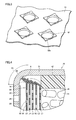
- Fig. 2 is a schematic perspective view of the filter shown in Fig. 1
- Fig. 3 is an enlarged perspective view of a surface portion of the plate-shaped portion of the filter shown in Fig. 1
- Fig. 4 is an enlarged view of an area in the vicinity of the upper curved corner portion of the gas generator shown in Fig. 1
- Fig. 5 is an enlarged view of an area in the vicinity of the lower curved corner portion of the gas generator shown in Fig. 1 .
- a detailed structure of filter 50 provided in gas generator 1A in the present embodiment and a structure for assembly to the housing will now be described with reference to these Figs. 2 to 5 in addition to Fig. 1 described above.
- filter 50 has a cylindrical portion 51 extending along the axial direction.
- Cylindrical portion 51 is formed as the plate-shaped portion made of metal is stacked in the radial direction and has a plurality of layers L1 to L5.
- the plurality of layers L1 to L5 forming cylindrical portion 51 are provided with a plurality of openings 52, and combustion chamber 40 and a space outside filter 50 communicate with each other through the plurality of openings 52.
- filter 50 is formed by winding a plate-shaped metal member having a plurality of openings 52, which is called hook metal.
- the plurality of openings 52 are formed by press-working (burring) and provided in each layer of L1 to L5 of filter 50 after winding.
- a protrusion 52a is formed around the periphery of opening 52 provided in cylindrical portion 51.
- This protrusion 52a is formed at the time of press-working (burring) for forming openings 52 in the plate-shaped metal member described above and formed by cutting to erect by a press of a presser.
- a pin in a pyramid or cone shape is suitably employed as a press.
- protrusion 52a leads to formation in filter 50, of layered gap portions 53 as shown in Fig. 1 .
- Gap portions 53 and openings 52 form in filter 50, a labyrinthine flow path allowing a space inside filter 50 and an outer space to communicate with each other.
- a position of protrusion 52a provided in filter 50 may be on an inner circumferential surface side or an outer circumferential surface side of each layer of L1 to L5 of filter 50.
- a roller may be used after press-working (burring) as necessary so as to roll protrusions 52a which have been cut to erect, so that protrusions 52a are in a shape conforming to the surface of the plate-shaped metal member as illustrated.
- sizes of gap portions 53 formed between layers L1 to L5 can be adjusted to a desired size. It is noted that, by varying pressing force at the time of rolling for each layer, a size of each gap portion 53 can also be varied for each layer.
- each of the plurality of layers L1 to L5 forming cylindrical portion 51 has a folded portion 54 at the axial end portion on the side where upper shell 20 is located. Folded portion 54 is formed by folding outward the axial end portion of cylindrical portion 51.
- filter 50 is assembled to the housing by being sandwiched in the axial direction between lower shell 10 and upper shell 20.
- an axial end portion on the side where upper shell 20 is located of the pair of axial end portions of filter 50 abuts to an inner peripheral surface of upper curved corner portion 23 of upper shell 20
- an axial end portion on the side where lower shell 10 is located of the pair of axial end portions of filter 50 abuts to an inner peripheral surface of lower curved corner portion 13 of lower shell 10.
- folded portion 54 is provided in each layer of L1 to L5 as described above at the axial end portion of filter 50 on the side where upper shell 20 is located, and a tip end of the folded portion (a portion shown with a character A in the figure) provided in the plate-shaped portion located in the outermost layer (that is, layer L5) of folded portions 54 provided in the plurality of layers L1 to L5 pressure-contacts upper curved corner portion 23 of upper shell 20 by coming in contact therewith along the circumferential direction.
- upper curved corner portion 23 has a shape smoothly curved within a range of a shown region R1 and the tip end above should only be in contact with upper shell 20 within the range of region R1.
- a tip end (a portion shown with a character B in the figure) of the plate-shaped portion located in the outermost layer (that is, layer L5) of the axial end portion of filter 50 on the side where lower shell 10 is located pressure-contacts lower curved corner portion 13 of lower shell 10 by coming in contact therewith along the circumferential direction.
- lower curved corner portion 13 has a shape smoothly curved within a range of a shown region R2 and the tip end above should only be in contact with lower shell 10 within the range of region R2.
- folded portion 54 provided in the plate-shaped portion located in outermost layer L5 described above deforms as it abuts to upper shell 20 during assembly, so that filter 50 pressure-contacts upper shell 20 and lower shell 10 at a moderate pressure and is fixed to the housing in the stable manner.
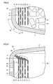
- Fig. 6 is an enlarged view of an area in the vicinity of the upper curved corner portion during actuation of the gas generator shown in Fig. 1
- Fig. 7 is an enlarged view of an area in the vicinity of the lower curved corner portion during actuation of the gas generator shown in Fig. 1 .
- Change in shape in the vicinity of upper curved corner portion 23 and in the vicinity of lower curved corner portion 13 during actuation of gas generator 1A in the present embodiment will now be described with reference to these Figs. 6 and 7 . It is noted that positions of upper shell 20 and lower shell 10 before actuation of gas generator 1A are shown with chain lines in Figs. 6 and 7 .
- upper shell 20 and lower shell 10 each deform outward. More specifically, in upper shell 20, top plate portion 21 deforms as it bulges upward, and in lower shell 10, bottom plate portion 11 deforms as it bulges downward.
- no or little deformation with increase in internal pressure in combustion chamber 40 occurs in upper curved corner portion 23 continuing to circumferential wall portion 22 and top plate portion 21 of upper shell 20, so that a state of abutment between the axial end portion of filter 50 on the side where upper shell 20 is located and upper curved corner portion 23 is maintained.
- no or little deformation with increase in internal pressure in combustion chamber 40 occurs either in lower curved corner portion 13 continuing to circumferential wall portion 12 and bottom plate portion 11 of lower shell 10 so that a state of abutment between the axial end portion of filter 50 on the side where lower shell 10 is located and lower curved corner portion 13 is maintained.
- a pair of axial end portions of filter 50 can always be maintained in a state pressure-contacted with upper shell 20 and lower shell 10 during actuation of gas generator 1A. Therefore, the gas can be prevented from discharging from gas discharge opening 24 without passing through filter 50.
- filter 50 itself functions as an effluence prevention member for preventing a gas from flowing out, and it is no longer necessary to separately provide an effluence prevention member formed from another part which has conventionally been necessary in the housing. Therefore, a gas generator with a simplified construction capable of reliably preventing a gas from flowing out through a gap between filter 50 and the housing can be obtained.
- a gas generator since it is no longer necessary to separately provide an effluence prevention member, a gas generator can also be lighter in weight.
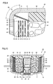
- Figs. 8 and 9 are enlarged views of an area in the vicinity of the upper curved corner portion of the gas generators according to first and second variations based on the present embodiment.
- the gas generators according to the first and second variations based on the present embodiment will now be described with reference to these Figs. 8 and 9 .
- folded portion 54 is provided only at the axial end portion of the plate-shaped portion located in outermost layer L5 of filter 50.
- folded portion 54 is provided only at the axial end portion of the plate-shaped portion located in innermost layer L1 of filter 50. Namely, in the gas generators according to these first and second variations, folded portion 54 is provided to extend only around a prescribed layer of cylindrical portion 51 forming filter 50 and no folded portion is provided in other layers.
- a pair of axial end portions of filter 50 can always be maintained in a state pressure-contacted with upper shell 20 and lower shell 10 during actuation, and thus an effect the same as the effect obtained in the case of gas generator 1A in the first embodiment of the present invention described above can be obtained.
- a layer where a folded portion abutting to upper curved corner portion 23 of upper shell 20 is formed is not limited to the outermost layer or the innermost layer as described above but it may be an intermediate layer located therebetween.
- Fig. 10 is a schematic diagram of a gas generator in a second embodiment of the present invention.
- a gas generator 1 B in the present embodiment will be described below with reference to this Fig. 10 .
- gas generator 1 B in the present embodiment is different from gas generator 1 A in the first embodiment of the present invention described above in a structure in the vicinity of lower curved corner portion 13 of lower shell 10.
- gas generator 1A in the first embodiment of the present invention described above is constructed such that the axial end portion of filter 50 located on the side of lower shell 10 abuts to lower curved corner portion 13 of lower shell 10, however, in gas generator 1 B in the present embodiment, the axial end portion abuts to bottom plate portion 11 of lower shell 10.
- an effluence prevention member 60 for supporting filter 50 and preventing a gas from flowing out through a gap between filter 50 and lower shell 10 is arranged at the end portion of combustion chamber 40 on the side of bottom plate portion 11 of lower shell 10.
- Effluence prevention member 60 is formed by press-working or the like a plate-shaped member made of metal such as stainless steel or iron steel, and it is formed from an annular member having a site abutting to the inner circumferential surface of the lower end portion of filter 50 and a site abutting to bottom plate portion 11 of lower shell 10.
- effluence prevention member 60 has moderate elasticity and moderately pressure-contacts each of the inner circumferential surface of filter 50 and bottom plate portion 11 of lower shell 10.
- filter 50 itself functions as an effluence prevention member for preventing a gas from flowing out at its upper end portion, and it is no longer necessary to separately provide on the upper side of the housing, an effluence prevention member formed from another part which has conventionally been necessary.
- a gas generator with a simplified construction capable of reliably preventing a gas from flowing out through a gap between filter 50 and the housing can be obtained.
- a gas generator can also be lighter in weight.
- one of the axial end portions of the filter is constructed to pressure-contact a flat plate portion of the housing as well, with such a construction that an effluence prevention member formed from another member is arranged in a portion with which one of the axial end portions is in contact and the other of the axial end portions pressure-contacts a curved corner portion of the housing, a gas generator with a construction more simplified than a conventional example, which is capable of reliably preventing a gas from flowing out from between the filter and the housing, can be obtained.
- Fig. 11 is a schematic diagram of a gas generator in a third embodiment of the present invention.
- a gas generator 1C in the present embodiment will be described below with reference to this Fig. 11 .
- gas generator 1C in the present embodiment is different from gas generator 1 A in the first embodiment of the present invention described above in a structure in the vicinity of lower curved corner portion 13 of lower shell 10 and a structure in the vicinity of upper curved corner portion 23 of upper shell 20.
- folded portion 54 is provided at the axial end portion of filter 50 located on the side of upper shell 20
- a folded portion 55 is provided at the axial end portion of filter 50 located on the side of lower shell 10.
- folded portion 55 is provided in each layer, at the axial end portion of filter 50 on the side where lower shell 10 is located, and among folded portions 55 provided in the plurality of layers, the tip end of the folded portion provided in the plate-shaped portion located in the outermost layer pressure-contacts lower curved corner portion 13 of lower shell 10 by coming in contact therewith along the circumferential direction.
- the tip end of the plate-shaped portion located in the outermost layer of the axial end portion of filter 50 on the side where upper shell 20 is located pressure-contacts upper curved corner portion 23 of upper shell 20 by coming in contact therewith along the circumferential direction.
- filter 50 itself functions as an effluence prevention member for preventing a gas from flowing out, and it is no longer necessary to separately provide in the housing, an effluence prevention member formed from another part which has conventionally been necessary. Therefore, in a case where filter 50 is formed from a stack structure of hook metal as well, a gas generator with a simplified construction capable of reliably preventing a gas from flowing out through a gap between filter 50 and the housing can be obtained. In addition, since it is no longer necessary to separately provide an effluence prevention member, a gas generator can also be lighter in weight.
- all layers from the innermost layer to the outermost layer may be constructed to abut to a curved corner portion, and only some or all of intermediate layers located between the innermost layer and the outermost layer may be constructed to abut to a curved corner portion (that is, neither of the innermost layer and the outermost layer abuts to a curved corner portion).
- the number of layers of the filter formed by winding a plate-shaped metal member is set to 5 has been exemplified for description, however, the number of layers is not limited to 5 and any number of layers may be set. Namely, a single layer or a plurality of layers other than 5 layers may be acceptable.
- a plate-shaped metal member can be formed from a single layer (that is, formed from a cylindrical member), a non-layered metal member can be assembled to the inside and/or the outside of the plate-shaped metal member of a single layer, and the filter can be formed from the plate-shaped metal member of a single layer and the non-layered metal member.
- non-layered metal member for example, a metal member obtained by winding and sintering a metal wire rod of stainless steel or iron steel, a metal member formed by press-working a mesh material into which metal wire rods are knitted to thereby pack the same, or the like is exemplified, and as the mesh material, a wire gauze of stocking stitch, a plain-woven wire gauze, an aggregate of crimped metal wire rods, or the like can be made use of.
- perforated metal refers to a metal plate provided only with openings in a plate-shaped metal member (that is, no protrusion is provided around a periphery of an opening)
- expanded metal refers to a metal plate obtained, for example, by making staggered cuts in a plate-shaped metal member and widening the cuts to thereby forming openings in the plate-shaped metal member in a mesh.
- a folded portion may naturally be provided at each of the axial end portions of a filter material.
- a bent portion may be formed by curving an axial end portion of the filter and the bent portion may be constructed to abut to the curved corner portion on the upper side and/or the lower side.
- a filter formed from a stack structure is formed by winding one plate-shaped member made of metal
- the construction of the filter is not limited as such. Namely, a filter formed from a stack structure may be formed by forming layers from separate plate-shaped members made of metal and combining these, or a filter made of a stack structure may be formed by forming some of a plurality of layers by winding one plate-shaped member made of metal, forming remaining layers by winding another plate-shaped member made of metal, and combining these.
- 1A to 1C gas generator 10 lower shell; 11 bottom plate portion; 12 circumferential wall portion; 13 lower curved corner portion; 14 holding portion; 15a, 15b crimping portion; 20 upper shell; 21 top plate portion; 22 circumferential wall portion; 23 upper curved corner portion; 24 gas discharge opening; 25 sealing member; 30 igniter; 31 ignition portion; 32 terminal pin; 33 sealing member; 34 cup; 34a flange portion; 35 enhancer chamber; 36 enhancer agent; 40 combustion chamber; 41 gas generating agent; 42 cushion material; 50 filter; 51 cylindrical portion; 52 opening; 52a protrusion; 53 gap portion; 54, 55 folded portion; and 60 effluence prevention member.
Landscapes
- Chemical & Material Sciences (AREA)
- Physics & Mathematics (AREA)
- Fluid Mechanics (AREA)
- Engineering & Computer Science (AREA)
- Mechanical Engineering (AREA)
- Organic Chemistry (AREA)
- Chemical Kinetics & Catalysis (AREA)
- Air Bags (AREA)
Abstract
A gas generator (1A) includes a housing including a lower shell (10) and an upper shell (20), an igniter (30), a gas generating agent (41), and a filter (50). The housing has a circumferential wall portion (12, 22) in a short, substantially cylindrical shape provided with a gas discharge opening (24) as well as a bottom plate portion (11) and a top plate portion (21) substantially in a disc shape closing axial end portions of the circumferential wall portion (12, 22). The filter (50) is formed from a stack structure made of a hollow, substantially cylindrical member and formed by winding hook metal. The housing further has, in a portion between the circumferential wall portion (22) and the top plate portion (21), an upper curved corner portion (23) which continues to each of these adjacent circumferential wall portion (22) and top plate portion (21) and is formed by abutment of an axial end portion of the filter (50) along a circumferential direction.
Description
- The present invention relates to a gas generator incorporated in a passenger protection apparatus, and more particularly to what is called a disc type gas generator incorporated in an air bag apparatus equipped in a steering wheel or the like of a car.
- From a point of view of protection of a driver and/or a passenger in a car or the like, an air bag apparatus which is a passenger protection apparatus has conventionally widely been used. The air bag apparatus is equipped for the purpose of protecting a driver and/or a passenger against shock caused at the time of collision of a vehicle or the like, and it receives a body of a driver or a passenger with an air bag serving as a cushion, as the air bag is expanded and developed instantaneously at the time of collision of the vehicle or the like. The gas generator is equipment which is incorporated in this air bag apparatus, an igniter therein being ignited in response to power feed through a control unit at the time of collision of a vehicle or the like to thereby bum a gas generating agent with flame caused by the igniter and instantaneously generate a large amount of gas, and thus expands and develops an air bag. It is noted that the air bag apparatus is equipped, for example, in a steering wheel, an instrument panel, or the like of a car.
- Gas generators of various structures are available, and in particular, what is called a disc type gas generator is available as a gas generator suitably made use of for a driver-seat-side air bag apparatus equipped in a steering wheel or the like. In general, the disc type gas generator has a short cylindrical housing of which axial end portions are closed, a gas discharge opening being provided in a circumferential wall of the housing, and the housing accommodating a gas generating agent, an igniter, a filter, and the like.
- Among these components, the filter functions as removal means for removing by catching slag (residues) contained in the gas generated in a combustion chamber, which is arranged to radially surround the combustion chamber accommodating a gas generating agent, and also functions as cooling means for lowering a temperature of the gas as the gas passes therethrough.
- Filters of various constructions are available as filters, and a filter formed by annularly winding a metal wire rod or a metal mesh member, a filter formed by annularly packing a metal wire rod or a metal mesh member by press-working, and the like are known as representative filters. The filter formed by thus annularly winding a metal wire rod or a metal mesh member or annularly packing a metal wire rod or a metal mesh member by press-working, however, suffers a problem of heavier weight or complicated manufacturing thereof.
- Therefore, from a point of view of lighter weight or facilitation of manufacturing, use of a filter formed by winding a plate-shaped metal member called hook metal as the filter has been proposed (see, for example, Japanese Patent Laying-Open No.
2009-286264 2010-234843 - In the filter formed by winding this hook metal, the above-described protrusions are located between a plurality of plate-shaped portions stacked in a radial direction, and presence of these protrusions leads to formation of layered gap portions inside. Then, a labyrinthine flow path is formed in the filter by the layered gap portions and the above-described openings so that a gas flows through this flow path and a cooling function and a slag catch function described above are effectively exhibited.
- In addition, it has been known that, in a case where no measures are taken in a disc type gas generator, a gas generated in a combustion chamber partly flows out through a gap between the filter and the housing during actuation and the gas may discharge through a gas discharge opening without passing through the filter. If such effluence of the gas through the gap occurs, not only desired output characteristics cannot be obtained but also such a problem that the gas is not sufficiently cooled or a large amount of slag is contained in the gas discharged from the gas generator arise.
- In order to prevent the gas from flowing out through the gap described above, generally in the disc type gas generator, such a construction that an effluence prevention member made of metal is arranged to extend along an inner circumferential surface of the filter defining the combustion chamber and along an inner surface of the housing and the effluence prevention member is brought in contact with each of the inner circumferential surface of the filter and the inner surface of the housing has been adopted (see, for example, Japanese Patent Laying-Open No.
10-287197 -
- PTD 1: Japanese Patent Laying-Open No.
2009-286264 - PTD 2: Japanese Patent Laying-Open No.
2010-234843 - PTD 3: Japanese Patent Laying-Open No.
10-287197 - In the gas generators disclosed in Japanese Patent Laying-Open No.
2009-286264 2010-234843 - Here, in the gas generator disclosed in these documents, by forming axial end portions of the filter from a folded portion or a bent portion, elastic biasing force is provided to the axial end portions. Consideration is thus given such that a state of abutment to the top plate portion and the bottom plate portion of the filter is maintained based on the elastic biasing force so as not to create the gap above even in the case where the top plate portion and the bottom plate portion of the housing deform.
- In the case where deformation of the top plate portion and the bottom plate portion is great, however, it becomes difficult to maintain the state of abutment above. Therefore, depending on specifications, a case where arrangement of an effluence prevention member described above is more preferred is also assumed. Thus, in the case where an effluence prevention member is arranged, a problem of complicated build-up operations with increase in the number of parts or a problem of failure to achieve sufficient weight reduction remains, and there can still be room for improvement in this regard.
- Therefore, the present invention was made to solve the problems described above, and an object thereof is to provide a gas generator with a simplified construction, capable of more reliably preventing a gas from flowing out through a gap between a filter and a housing.
- A gas generator based on the present invention includes a housing, an igniter, and a filter. The housing has a circumferential wall portion in a short, substantially cylindrical shape provided with a gas discharge opening and a pair of end wall portions substantially in a disc shape closing axial end portions of the circumferential wall portion and containing a combustion chamber accommodating a gas generating agent. The igniter is attached to one of the pair of end wall portions so as to face the combustion chamber. The filter is formed from a member in a hollow, substantially cylindrical shape disposed in the housing. The filter includes a plate-shaped portion made of metal, which extends along a circumferential direction so as to surround the combustion chamber in a radial direction of the housing and is provided with a plurality of openings, and it is fixed to the housing by being sandwiched by the housing in an axial direction. The housing further has a curved corner portion which continues to each of adjacent circumferential wall portion and end wall portion and is formed by abutment of axial end portions of the plate-shaped portion of the filter along a circumferential direction, in at least one of portions between the circumferential wall portion and the pair of end wall portions.
- In the gas generator based on the present invention above, preferably, the curved corner portion to which the axial end portion of the plate-shaped portion of the filter abuts is at least located between an end wall portion which is different from the end wall portion to which the igniter is attached and the circumferential wall portion.
- In the gas generator based on the present invention above, preferably, the axial end portion of the plate-shaped portion of the filter, which abuts to the curved corner portion, is formed from a folded portion formed by folding the plate-shaped portion or a bent portion formed by bending the plate-shaped portion.
- In the gas generator based on the present invention above, preferably, the plate-shaped portion has a protrusion around a periphery of the opening, and preferably, the filter is formed from a stack structure which is formed such that the plate-shaped portion having the protrusion is stacked in a radial direction to thereby form layered gap portions therein.
- In the gas generator based on the present invention above, preferably, the axial end portion of the plate-shaped portion of the filter, which abuts to the curved corner portion, is formed from an axial end portion of the plate-shaped portion located at least in an outermost layer of the stacked plate-shaped portions.
- In the gas generator based on the present invention above, preferably, the axial end portion of the plate-shaped portion of the filter, which abuts to the curved corner portion, is formed from an axial end portion of the plate-shaped portion located at least in an innermost layer of the stacked plate-shaped portions.
- In the gas generator based on the present invention above, preferably, the filter is formed from a stack structure formed by winding one plate-shaped member made of metal.
- According to the present invention, a gas generator with a simplified construction, capable of reliably preventing a gas from flowing out through a gap between a filter and a housing can be obtained.
-
-
Fig. 1 is a schematic diagram of a gas generator in a first embodiment of the present invention. -
Fig. 2 is a schematic perspective view of a filter shown inFig. 1 . -
Fig. 3 is an enlarged perspective view of a surface portion of a plate-shaped portion of the filter shown inFig. 1 . -
Fig. 4 is an enlarged view of an area in the vicinity of an upper curved corner portion of the gas generator shown inFig. 1 . -
Fig. 5 is an enlarged view of an area in the vicinity of a lower curved corner portion of the gas generator shown inFig. 1 . -
Fig. 6 is an enlarged view of the area in the vicinity of the upper curved corner portion during actuation of the gas generator shown inFig. 1 . -
Fig. 7 is an enlarged view of the area in the vicinity of the lower curved corner portion during actuation of the gas generator shown inFig. 1 . -
Fig. 8 is an enlarged view of an area in the vicinity of the upper curved corner portion of the gas generator according to a first variation. -
Fig. 9 is an enlarged view of an area in the vicinity of the upper curved corner portion of the gas generator according to a second variation. -
Fig. 10 is a schematic diagram of a gas generator in a second embodiment of the present invention. -
Fig. 11 is a schematic diagram of a gas generator in a third embodiment of the present invention. - An embodiment of the present invention will be described hereinafter in detail with reference to the drawings. An embodiment and a variation thereof shown below represent application of the present invention to a disc type gas generator incorporated in an air bag apparatus equipped in a steering wheel or the like of a car. It is noted that the same or common elements in the embodiment and the variation thereof shown below have the same reference characters allotted in the drawings and description thereof will not be repeated.
-
Fig. 1 is a schematic diagram of a gas generator in a first embodiment of the present invention. An overall structure of agas generator 1A in the present embodiment will initially be described with reference to thisFig. 1 . - As shown in
Fig. 1 ,gas generator 1A in the present embodiment has a housing of which outer shape is in a short, substantially columnar shape and which has opposing axial ends closed and accommodates various components therein. The housing has a circumferential wall portion in a short, substantially cylindrical shape and a pair of end wall portions substantially in a disc shape closing axial end portions of this circumferential wall portion. These circumferential wall portion and pair of end wall portions are formed by combining alower shell 10 and anupper shell 20 formed in a substantially cylindrical shape with bottom such that opening surfaces thereof face each other. - More specifically,
lower shell 10 has acircumferential wall portion 12, abottom plate portion 11 corresponding to one of the pair of end wall portions, and a lowercurved corner portion 13 located therebetween and continuing to each ofcircumferential wall portion 12 andbottom plate portion 11, andupper shell 20 has acircumferential wall portion 22, atop plate portion 21 corresponding to the other of the pair of end wall portions, and an uppercurved corner portion 23 located therebetween and continuing to each ofcircumferential wall portion 22 andbottom plate portion 21. -
Lower shell 10 andupper shell 20 are each formed from a member made of metal such as stainless steel, iron steel, an aluminum alloy, and a stainless alloy.Lower shell 10 andupper shell 20 are formed from a metal member in a shape of a plate or a piece of block with the use of a mold or the like, through forging, drawing, press-working, or the like, or combination thereof. In addition, electron-beam welding, laser welding, friction welding, or the like is suitably made use of for joininglower shell 10 andupper shell 20 to each other. - A holding
portion 14 is formed in a substantially central portion ofbottom plate portion 11 oflower shell 10. This holdingportion 14 is a site for holding anigniter 30. Specifically,igniter 30 is attached from an inner side oflower shell 10 to holdingportion 14 such that aterminal pin 32 ofigniter 30 is inserted through an opening provided in holdingportion 14, and a crimpingportion 15a provided at a tip end of holdingportion 14 is crimped towardigniter 30 in this state, so thatigniter 30 is fixed by crimping to holdingportion 14 oflower shell 10. It is noted that a connector (not shown) of a harness for connectingigniter 30 and a control unit to each other is connected toterminal pin 32 arranged to be exposed to the outside of the housing. -
Igniter 30 is an ignition device for producing flame and includes anignition portion 31 andterminal pin 32 described above.Ignition portion 31 has a squib cup made of metal or plastic, and contains an ignition agent ignited at the time of actuation and a resistor (bridge wire) for burning this ignition agent.Terminal pin 32 is connected to the resistor for igniting the ignition agent. A Nichrome wire or the like is generally made use of as a resistor, and ZPP (zirconium potassium perchlorate), ZWPP (zirconium tungsten potassium perchlorate), lead tricinate, or the like is generally made use of as the ignition agent. - Upon sensing collision, a prescribed amount of current flows in a resistor through
terminal pin 32. As the prescribed amount of current flows in the resistor, Joule heat is generated in the resistor and the ignition agent starts burning. Flame at a high temperature caused by burning causes a squib cup storing the ignition agent to burst. A time period from flow of a current in the resistor until actuation ofigniter 30 is generally not longer than 2 milliseconds in the case where a Nichrome wire is made use of for the resistor. - A sealing
member 33 is interposed betweenigniter 30 and holdingportion 14. Sealingmember 33 serves to hermetically seal anenhancer chamber 35 which will be described later by air-tightly sealing a gap created betweenigniter 30 and holdingportion 14, and it is inserted in the gap in fixing by crimpingigniter 30 to holdingportion 14. A sealing member made of a material having sufficient heat resistance and durability is preferably made use of as sealingmember 33, and for example, an O ring or the like made of an EPDM resin representing one type of ethylene propylene rubber is suitably made use of. - It is noted that hermeticity of
enhancer chamber 35 can further be enhanced by separately applying a liquid sealing agent to a portion where sealingmember 33 is to be interposed. Here, a liquid sealing agent containing a resin material excellent in heat resistance, durability, corrosion resistance, and the like after curing is suitably selected and made use of as the liquid sealing agent, and for example, a cyanoacrylate-based resin or a silicone-based resin is particularly suitably made use of as the resin material. In addition, for the resin material, other than the resin materials described above, a phenol-based resin, an epoxy-based resin, a melamine-based resin, a urea-based resin, a polyester-based resin, an alkyd-based resin, a polyurethane-based resin, a polyimide-based resin, a polyethylene-based resin, a polypropylene-based resin, a polyvinyl chloride-based resin, a polystyrene-based resin, a polyvinyl acetate-based resin, a polytetrafluoroethylene-based resin, an acrylonitrile butadiene styrene-based resin, an acrylonitrile styrene-based resin, an acryl-based resin, a polyamide-based resin, a polyacetal-based resin, a polycarbonate-based resin, a polyphenylene ether-based resin, a polybutylene terephthalate-based resin, a polyethylene terephthalate-based resin, a polyolefin-based resin, a polyphenylene sulfide-based resin, a polysulfone-based resin, a polyether sulfone-based resin, a polyarylate-based resin, a polyether ether ketone-based resin, a polyamide imide-based resin, a liquid crystal polymer, and the like can be made use of. - A
cylindrical cup 34 with bottom is fixed to holdingportion 14 oflower shell 10 so as to coverigniter 30.Cup 34 has a top wall portion and a sidewall portion, and containsenhancer chamber 35 accommodating anenhancer agent 36.Cup 34 is fixed to holdingportion 14 such thatenhancer chamber 35 provided therein facesignition portion 31. More specifically, aflange portion 34a is provided to protrude outward, at an end portion on an opening end side ofcup 34 andflange portion 34a ofcup 34 is crimped by a crimpingportion 15b provided in holdingportion 14, so thatcup 34 is fixed to holdingportion 14. -
Cup 34 completely hermetically sealsenhancer chamber 35 provided therein while it is fixed to holdingportion 14 oflower shell 10. Thiscup 34 bursts or melts with increase in pressure or with transfer of generated heat withinenhancer chamber 35 whenigniter 30 is actuated andenhancer agent 36 is ignited. It is noted that aluminum, an aluminum alloy, plastic, or the like is suitably made use of as a material forcup 34. -
Enhancer agent 36 loaded inenhancer chamber 35 produces thermal particles as it is ignited by the flame caused by actuation ofigniter 30 and it bums.Enhancer agent 36 should be able to reliably start burning agas generating agent 41 which will be described later, and generally, a composition or the like composed of metal powders/oxidizing agent represented by B/KNO3 or the like is employed. Forenhancer agent 36, a powdery enhancer agent, an enhancer agent formed in a prescribed shape by a binder, or the like is made use of. A shape of the enhancer agent formed by a binder includes, for example, various shapes such as a granule, a column, a sheet, a sphere, a cylinder with a single hole, a cylinder with multiple holes, a tablet, and the like. - A
combustion chamber 40 accommodatinggas generating agent 41 is located in a space surrounding a portion wherecup 34 described above is arranged, in the space inside the housing constituted oflower shell 10 andupper shell 20. More specifically,cup 34 described above is arranged to protrude intocombustion chamber 40 formed in the inside of the housing, and a space provided in a portion facing an outer surface of a sidewall portion of thiscup 34 is formed ascombustion chamber 40. - In addition, in a space radially surrounding
combustion chamber 40 accommodating thisgas generating agent 41, afilter 50 is arranged along an inner circumference of the housing.Filter 50 has a hollow cylindrical shape, and is arranged coaxially with the housing.Filter 50 is formed from a stack structure formed by radially stacking a plate-shaped portion made of metal and it is suitably formed from a stack structure formed by winding one plate-shaped member made of metal. For example, a steel plate (mild steel) or a stainless steel plate can suitably be made use of as a plate-shaped member made of metal, and a nonferrous metal plate of aluminum, copper, titanium, nickel, or an alloy thereof, or the like can also be made use of. It is noted that a detailed structure of thisfilter 50 and a structure for assembly thereof to the housing will be described later. -
Gas generating agent 41 is an agent which is ignited by thermal particles generated as a result of actuation ofigniter 30 and produces a gas as it bums. A non-azide-based gas generating agent is preferably employed asgas generating agent 41, andgas generating agent 41 is formed as a molding generally containing a fuel, an oxidizing agent, and an additive. For the fuel, for example, a triazole derivative, a tetrazole derivative, a guanidine derivative, an azodicarbonamide derivative, a hydrazine derivative, or the like, or combination thereof is made use of. Specifically, for example, nitroguanidine, guanidine nitrate, cyanoguanidine, 5-aminotetrazole, and the like are suitably made use of. In addition, as the oxidizing agent, for example, basic nitrate such as basic copper nitrate, perchlorate such as ammonium perchlorate or potassium perchlorate, nitrate containing cations selected from an alkali metal, an alkali earth metal, a transition metal, and ammonia, or the like is made use of. As the nitrate, for example, sodium nitrate, potassium nitrate, or the like is suitably made use of. Moreover, as the additive, a binder, a slag formation agent, a combustion modifier, or the like is exemplified. As the binder, for example, metal salt of carboxymethyl cellulose, an organic binder such as stearate, or an inorganic binder such as synthetic hydrotalcite and Japanese acid clay can suitably be made use of. As the slag formation agent, silicon nitride, silica, Japanese acid clay, or the like can suitably be made use of. In addition, as the combustion modifier, a metal oxide, ferrosilicon, activated carbon, graphite, or the like can suitably be made use of. - A shape of a molding of
gas generating agent 41 includes various shapes such as a particulate shape including a granule, a pellet, and a column, and a disc shape. In addition, among columnar moldings, a molding with holes having holes in the molding (such as a cylindrical shape with a single hole or a cylindrical shape with multiple holes) is also made use of. These shapes are preferably selected as appropriate depending on specifications of an air bag apparatus in whichgas generator 1 A is incorporated, and for example, a shape optimal for the specifications is preferably selected by selecting a shape allowing change over time of a rate of generation of a gas during burning ofgas generating agent 41. Furthermore, in addition to a shape ofgas generating agent 41, a size of a molding or an amount thereof for filling is preferably selected as appropriate, in consideration of a linear burning velocity, a pressure exponent, or the like ofgas generating agent 41. -
Filter 50 functions as cooling means for cooling a gas by depriving heat at a high temperature of the gas when the gas produced incombustion chamber 40 passes through thisfilter 50 and also functions as removal means for removing by catching, slag (residues) contained in the gas. Therefore, in order to sufficiently cool the gas and to avoid emission of the slag to the outside, the gas produced incombustion chamber 40 should be caused to reliably pass throughfilter 50. - An outer circumferential surface of
filter 50 is located at a prescribed distance from the inner circumferential surface ofcircumferential wall portion 12 oflower shell 10 and the inner circumferential surface ofcircumferential wall portion 22 ofupper shell 20. A plurality ofgas discharge openings 24 are provided incircumferential wall portion 22 ofupper shell 20 in aportion facing filter 50. This gas discharge opening 24 serves to guide an actuation gas which has passed throughfilter 50 to the outside of the housing. To a main surface ofcircumferential wall portion 22 ofupper shell 20, which is located on a side offilter 50, a sealingmember 25 is attached to closegas discharge opening 24. An aluminum foil or the like having an adhesive member applied to its one surface is made use of as this sealingmember 25. Thus, hermeticity ofcombustion chamber 40 is ensured. - At an end portion of
upper shell 20 ofcombustion chamber 40, on the side oftop plate portion 21, acushion material 42 is arranged to be in contact withgas generating agent 41 accommodated incombustion chamber 40. Thiscushion material 42 is provided for the purpose of preventinggas generating agent 41 made of a molding from being crushed by vibration or the like, and a molding of ceramics fibers or a foamed resin (such as foamed silicone) is suitably made use of. - An operation of
gas generator 1A in the present embodiment will now be described with reference toFig. 1 . - When a vehicle on which
gas generator 1A in the present embodiment is mounted collides, collision sensing means separately provided in the vehicle senses collision, and based thereon,igniter 30 is actuated in response to power feed through a control unit separately provided in the vehicle.Enhancer agent 36 accommodated inenhancer chamber 35 burns as it is ignited by flame produced as a result of actuation ofigniter 30 and produces a large number of thermal particles. As thisenhancer agent 36 bums,cup 34 bursts or melts and thermal particles described above flow intocombustion chamber 40. - Thermal particles which have flowed in ignite and bum
gas generating agent 41 accommodated incombustion chamber 40 and a large amount of gas is produced. The gas produced incombustion chamber 40 passes throughfilter 50. At that time, heat is deprived of the gas throughfilter 50 and the gas is cooled, slag contained in the gas is removed byfilter 50, and the gas flows into an outer peripheral portion of the housing. - As an internal pressure in the housing increases, sealing by sealing
member 25 which has closed gas discharge opening 24 ofupper shell 20 is broken, and the gas is discharged to the outside of the housing throughgas discharge opening 24. The discharged gas is introduced in the air bag provided adjacent togas generator 1A and it expands and develops the air bag. -
Fig. 2 is a schematic perspective view of the filter shown inFig. 1 , andFig. 3 is an enlarged perspective view of a surface portion of the plate-shaped portion of the filter shown inFig. 1 . In addition,Fig. 4 is an enlarged view of an area in the vicinity of the upper curved corner portion of the gas generator shown inFig. 1 , andFig. 5 is an enlarged view of an area in the vicinity of the lower curved corner portion of the gas generator shown inFig. 1 . A detailed structure offilter 50 provided ingas generator 1A in the present embodiment and a structure for assembly to the housing will now be described with reference to theseFigs. 2 to 5 in addition toFig. 1 described above. - As shown in
Figs. 1 and 2 , filter 50 has acylindrical portion 51 extending along the axial direction.Cylindrical portion 51 is formed as the plate-shaped portion made of metal is stacked in the radial direction and has a plurality of layers L1 to L5. The plurality of layers L1 to L5 formingcylindrical portion 51 are provided with a plurality ofopenings 52, andcombustion chamber 40 and a space outsidefilter 50 communicate with each other through the plurality ofopenings 52. - As shown in
Fig. 3 , filter 50 is formed by winding a plate-shaped metal member having a plurality ofopenings 52, which is called hook metal. The plurality ofopenings 52 are formed by press-working (burring) and provided in each layer of L1 to L5 offilter 50 after winding. - Here, a
protrusion 52a is formed around the periphery of opening 52 provided incylindrical portion 51. Thisprotrusion 52a is formed at the time of press-working (burring) for formingopenings 52 in the plate-shaped metal member described above and formed by cutting to erect by a press of a presser. In order to formprotrusion 52a in a shape as illustrated, a pin in a pyramid or cone shape is suitably employed as a press. - Presence of
protrusion 52a above leads to formation infilter 50, of layeredgap portions 53 as shown inFig. 1 .Gap portions 53 andopenings 52 form infilter 50, a labyrinthine flow path allowing a space insidefilter 50 and an outer space to communicate with each other. It is noted that a position ofprotrusion 52a provided infilter 50 may be on an inner circumferential surface side or an outer circumferential surface side of each layer of L1 to L5 offilter 50. - In addition, in
filter 50, a roller may be used after press-working (burring) as necessary so as to rollprotrusions 52a which have been cut to erect, so thatprotrusions 52a are in a shape conforming to the surface of the plate-shaped metal member as illustrated. In such a case, since heights ofprotrusions 52a can be set to the same desired height, sizes ofgap portions 53 formed between layers L1 to L5 can be adjusted to a desired size. It is noted that, by varying pressing force at the time of rolling for each layer, a size of eachgap portion 53 can also be varied for each layer. - As shown in
Figs. 1, 2 , and4 , each of the plurality of layers L1 to L5 formingcylindrical portion 51 has a foldedportion 54 at the axial end portion on the side whereupper shell 20 is located. Foldedportion 54 is formed by folding outward the axial end portion ofcylindrical portion 51. - As shown in
Fig. 1 , filter 50 is assembled to the housing by being sandwiched in the axial direction betweenlower shell 10 andupper shell 20. Here, an axial end portion on the side whereupper shell 20 is located of the pair of axial end portions offilter 50 abuts to an inner peripheral surface of uppercurved corner portion 23 ofupper shell 20, and an axial end portion on the side wherelower shell 10 is located of the pair of axial end portions offilter 50 abuts to an inner peripheral surface of lowercurved corner portion 13 oflower shell 10. - More specifically, as shown in
Fig. 4 , foldedportion 54 is provided in each layer of L1 to L5 as described above at the axial end portion offilter 50 on the side whereupper shell 20 is located, and a tip end of the folded portion (a portion shown with a character A in the figure) provided in the plate-shaped portion located in the outermost layer (that is, layer L5) of foldedportions 54 provided in the plurality of layers L1 to L5 pressure-contacts uppercurved corner portion 23 ofupper shell 20 by coming in contact therewith along the circumferential direction. Here, uppercurved corner portion 23 has a shape smoothly curved within a range of a shown region R1 and the tip end above should only be in contact withupper shell 20 within the range of region R1. - On the other hand, as shown in
Fig. 5 , a tip end (a portion shown with a character B in the figure) of the plate-shaped portion located in the outermost layer (that is, layer L5) of the axial end portion offilter 50 on the side wherelower shell 10 is located pressure-contacts lowercurved corner portion 13 oflower shell 10 by coming in contact therewith along the circumferential direction. Here, lowercurved corner portion 13 has a shape smoothly curved within a range of a shown region R2 and the tip end above should only be in contact withlower shell 10 within the range of region R2. - From the foregoing, folded
portion 54 provided in the plate-shaped portion located in outermost layer L5 described above deforms as it abuts toupper shell 20 during assembly, so thatfilter 50 pressure-contactsupper shell 20 andlower shell 10 at a moderate pressure and is fixed to the housing in the stable manner. -
Fig. 6 is an enlarged view of an area in the vicinity of the upper curved corner portion during actuation of the gas generator shown inFig. 1 , andFig. 7 is an enlarged view of an area in the vicinity of the lower curved corner portion during actuation of the gas generator shown inFig. 1 . Change in shape in the vicinity of uppercurved corner portion 23 and in the vicinity of lowercurved corner portion 13 during actuation ofgas generator 1A in the present embodiment will now be described with reference to theseFigs. 6 and7 . It is noted that positions ofupper shell 20 andlower shell 10 before actuation ofgas generator 1A are shown with chain lines inFigs. 6 and7 . - As shown in
Figs. 6 and7 , during actuation ofgas generator 1A, with increase in internal pressure incombustion chamber 40 due to combustion ofgas generating agent 41,upper shell 20 andlower shell 10 each deform outward. More specifically, inupper shell 20,top plate portion 21 deforms as it bulges upward, and inlower shell 10,bottom plate portion 11 deforms as it bulges downward. - Here, no or little deformation with increase in internal pressure in
combustion chamber 40 occurs in uppercurved corner portion 23 continuing tocircumferential wall portion 22 andtop plate portion 21 ofupper shell 20, so that a state of abutment between the axial end portion offilter 50 on the side whereupper shell 20 is located and uppercurved corner portion 23 is maintained. In addition, no or little deformation with increase in internal pressure incombustion chamber 40 occurs either in lowercurved corner portion 13 continuing tocircumferential wall portion 12 andbottom plate portion 11 oflower shell 10 so that a state of abutment between the axial end portion offilter 50 on the side wherelower shell 10 is located and lowercurved corner portion 13 is maintained. - Therefore, no gap is created between
filter 50 andupper shell 20 and betweenfilter 50 andlower shell 10, a gas can effectively be prevented from flowing out from therebetween, and the gas can reliably discharge to the outside throughfilter 50. Even if uppercurved corner portion 23 and lowercurved corner portion 13 deform, an amount of deformation thereof is much smaller than deformation caused intop plate portion 21 orbottom plate portion 11 because the shape of these corner portions are in a curved shape. In that case as well, by providing foldedportion 54 described above, deformation of uppercurved corner portion 23 and lowercurved corner portion 13 is followed owing to elastic force provided to filter 50 and a state of abutment offilter 50 to uppercurved corner portion 23 and lowercurved corner portion 13 is maintained so that a gas can effectively be prevented from flowing out. - According to
gas generator 1A in the present embodiment described above, a pair of axial end portions offilter 50 can always be maintained in a state pressure-contacted withupper shell 20 andlower shell 10 during actuation ofgas generator 1A. Therefore, the gas can be prevented from discharging from gas discharge opening 24 without passing throughfilter 50. Namely, filter 50 itself functions as an effluence prevention member for preventing a gas from flowing out, and it is no longer necessary to separately provide an effluence prevention member formed from another part which has conventionally been necessary in the housing. Therefore, a gas generator with a simplified construction capable of reliably preventing a gas from flowing out through a gap betweenfilter 50 and the housing can be obtained. In addition, since it is no longer necessary to separately provide an effluence prevention member, a gas generator can also be lighter in weight. -
Figs. 8 and9 are enlarged views of an area in the vicinity of the upper curved corner portion of the gas generators according to first and second variations based on the present embodiment. The gas generators according to the first and second variations based on the present embodiment will now be described with reference to theseFigs. 8 and9 . - As shown in
Fig. 8 , in the gas generator according to the first variation, foldedportion 54 is provided only at the axial end portion of the plate-shaped portion located in outermost layer L5 offilter 50. On the other hand, as shown inFig. 9 , in the gas generator according to the second variation, foldedportion 54 is provided only at the axial end portion of the plate-shaped portion located in innermost layer L1 offilter 50. Namely, in the gas generators according to these first and second variations, foldedportion 54 is provided to extend only around a prescribed layer ofcylindrical portion 51 formingfilter 50 and no folded portion is provided in other layers. - In a case of such a construction as well, a pair of axial end portions of
filter 50 can always be maintained in a state pressure-contacted withupper shell 20 andlower shell 10 during actuation, and thus an effect the same as the effect obtained in the case ofgas generator 1A in the first embodiment of the present invention described above can be obtained. It is noted that a layer where a folded portion abutting to uppercurved corner portion 23 ofupper shell 20 is formed is not limited to the outermost layer or the innermost layer as described above but it may be an intermediate layer located therebetween. -
Fig. 10 is a schematic diagram of a gas generator in a second embodiment of the present invention. Agas generator 1 B in the present embodiment will be described below with reference to thisFig. 10 . - As shown in
Fig. 10 ,gas generator 1 B in the present embodiment is different fromgas generator 1 A in the first embodiment of the present invention described above in a structure in the vicinity of lowercurved corner portion 13 oflower shell 10. Namely,gas generator 1A in the first embodiment of the present invention described above is constructed such that the axial end portion offilter 50 located on the side oflower shell 10 abuts to lowercurved corner portion 13 oflower shell 10, however, ingas generator 1 B in the present embodiment, the axial end portion abuts tobottom plate portion 11 oflower shell 10. - In addition, in
gas generator 1 B in the present embodiment, aneffluence prevention member 60 for supportingfilter 50 and preventing a gas from flowing out through a gap betweenfilter 50 andlower shell 10 is arranged at the end portion ofcombustion chamber 40 on the side ofbottom plate portion 11 oflower shell 10.Effluence prevention member 60 is formed by press-working or the like a plate-shaped member made of metal such as stainless steel or iron steel, and it is formed from an annular member having a site abutting to the inner circumferential surface of the lower end portion offilter 50 and a site abutting tobottom plate portion 11 oflower shell 10. Here,effluence prevention member 60 has moderate elasticity and moderately pressure-contacts each of the inner circumferential surface offilter 50 andbottom plate portion 11 oflower shell 10. - In the case of such a construction as well, the axial end portion of
filter 50 on the side located inupper shell 20 can always be maintained in a state pressure-contacted withupper shell 20 during actuation ofgas generator 1B, and hence a gas can be prevented from discharging from gas discharge opening 24 without passing throughfilter 50. Namely, filter 50 itself functions as an effluence prevention member for preventing a gas from flowing out at its upper end portion, and it is no longer necessary to separately provide on the upper side of the housing, an effluence prevention member formed from another part which has conventionally been necessary. Therefore, in a case wherefilter 50 is formed from a stack structure of hook metal as well, a gas generator with a simplified construction capable of reliably preventing a gas from flowing out through a gap betweenfilter 50 and the housing can be obtained. In addition, since it is no longer necessary to separately provide an effluence prevention member on the upper side of the housing, a gas generator can also be lighter in weight. - Thus, in a case where one of the axial end portions of the filter is constructed to pressure-contact a flat plate portion of the housing as well, with such a construction that an effluence prevention member formed from another member is arranged in a portion with which one of the axial end portions is in contact and the other of the axial end portions pressure-contacts a curved corner portion of the housing, a gas generator with a construction more simplified than a conventional example, which is capable of reliably preventing a gas from flowing out from between the filter and the housing, can be obtained.
-
Fig. 11 is a schematic diagram of a gas generator in a third embodiment of the present invention. A gas generator 1C in the present embodiment will be described below with reference to thisFig. 11 . - As shown in
Fig. 11 , gas generator 1C in the present embodiment is different fromgas generator 1 A in the first embodiment of the present invention described above in a structure in the vicinity of lowercurved corner portion 13 oflower shell 10 and a structure in the vicinity of uppercurved corner portion 23 ofupper shell 20. Namely, ingas generator 1A in the first embodiment of the present invention described above, foldedportion 54 is provided at the axial end portion offilter 50 located on the side ofupper shell 20, however, in gas generator 1C in the present embodiment, a foldedportion 55 is provided at the axial end portion offilter 50 located on the side oflower shell 10. - More specifically, folded
portion 55 is provided in each layer, at the axial end portion offilter 50 on the side wherelower shell 10 is located, and among foldedportions 55 provided in the plurality of layers, the tip end of the folded portion provided in the plate-shaped portion located in the outermost layer pressure-contacts lowercurved corner portion 13 oflower shell 10 by coming in contact therewith along the circumferential direction. On the other hand, the tip end of the plate-shaped portion located in the outermost layer of the axial end portion offilter 50 on the side whereupper shell 20 is located pressure-contacts uppercurved corner portion 23 ofupper shell 20 by coming in contact therewith along the circumferential direction. - In the case of such a construction as well, during actuation of gas generator 1C, a pair of axial end portions of
filter 50 can always be maintained in a state pressure-contacted withlower shell 10 andupper shell 20, and therefore a gas can be prevented from discharging from gas discharge opening 24 without passing throughfilter 50. Namely, filter 50 itself functions as an effluence prevention member for preventing a gas from flowing out, and it is no longer necessary to separately provide in the housing, an effluence prevention member formed from another part which has conventionally been necessary. Therefore, in a case wherefilter 50 is formed from a stack structure of hook metal as well, a gas generator with a simplified construction capable of reliably preventing a gas from flowing out through a gap betweenfilter 50 and the housing can be obtained. In addition, since it is no longer necessary to separately provide an effluence prevention member, a gas generator can also be lighter in weight. - In the first to third embodiments and the variations thereof of the present invention described above, a case where only any of an outermost layer and an innermost layer of a filter formed by winding a plate-shaped metal member is constructed to abut to a curved corner portion of a housing has been exemplified for description, however, the outermost layer and a plurality of layers inside thereof may be constructed to abut to a curved corner portion or the innermost layer and a plurality of layers outside thereof may be constructed to abut to a curved corner portion. In addition, all layers from the innermost layer to the outermost layer may be constructed to abut to a curved corner portion, and only some or all of intermediate layers located between the innermost layer and the outermost layer may be constructed to abut to a curved corner portion (that is, neither of the innermost layer and the outermost layer abuts to a curved corner portion).
- Moreover, in the first to third embodiments and the variations thereof of the present invention described above, a case where the number of layers of the filter formed by winding a plate-shaped metal member is set to 5 has been exemplified for description, however, the number of layers is not limited to 5 and any number of layers may be set. Namely, a single layer or a plurality of layers other than 5 layers may be acceptable.
- Furthermore, a plate-shaped metal member can be formed from a single layer (that is, formed from a cylindrical member), a non-layered metal member can be assembled to the inside and/or the outside of the plate-shaped metal member of a single layer, and the filter can be formed from the plate-shaped metal member of a single layer and the non-layered metal member. Here, as the non-layered metal member, for example, a metal member obtained by winding and sintering a metal wire rod of stainless steel or iron steel, a metal member formed by press-working a mesh material into which metal wire rods are knitted to thereby pack the same, or the like is exemplified, and as the mesh material, a wire gauze of stocking stitch, a plain-woven wire gauze, an aggregate of crimped metal wire rods, or the like can be made use of.
- In addition, in the first to third embodiments and the variations thereof of the present invention described above, a case where a filter fabricated by winding what is called hook metal is made use of as the filter has been exemplified, however, alternatively, a filter fabricated by winding perforated metal can also be made use of and a filter fabricated by winding expanded metal can also be made use of. Here, perforated metal refers to a metal plate provided only with openings in a plate-shaped metal member (that is, no protrusion is provided around a periphery of an opening), and expanded metal refers to a metal plate obtained, for example, by making staggered cuts in a plate-shaped metal member and widening the cuts to thereby forming openings in the plate-shaped metal member in a mesh. In a case where such perforated metal or expanded metal is employed instead of hook metal described above as well, an effect the same as the effect described in the first to third embodiments and the variations thereof of the present invention described above can be obtained.
- Moreover, in the first to third embodiments and the variations thereof of the present invention described above, a case where a folded portion is provided at one of axial end portions of the filter has been exemplified for description, however, a folded portion may naturally be provided at each of the axial end portions of a filter material. Furthermore, instead of the folded portion, a bent portion may be formed by curving an axial end portion of the filter and the bent portion may be constructed to abut to the curved corner portion on the upper side and/or the lower side. Additionally, it is not essential to provide the folded portion, the bent portion, or the like at the axial end portion of the filter, and a filter not including the same could achieve a corresponding effect provided that at least one of axial end portions thereof abuts to a curved corner portion of the housing.
- In addition, in the first to third embodiments and the variations thereof of the present invention described above, a case where a filter formed from a stack structure is formed by winding one plate-shaped member made of metal has been exemplified for description, however, the construction of the filter is not limited as such. Namely, a filter formed from a stack structure may be formed by forming layers from separate plate-shaped members made of metal and combining these, or a filter made of a stack structure may be formed by forming some of a plurality of layers by winding one plate-shaped member made of metal, forming remaining layers by winding another plate-shaped member made of metal, and combining these.
- Moreover, characteristic features of the gas generators according to the first to third embodiments and variations thereof of the present invention described above can naturally be combined with one another within the scope allowable in light of the gist of the present invention.
- Thus, each embodiment and a variation thereof above disclosed herein are illustrative and non-restrictive in every respect. The technical scope of the present invention is delimited by the terms of the claims and is intended to include any modifications within the scope and meaning equivalent to the terms of the claims.
- 1A to 1C gas generator; 10 lower shell; 11 bottom plate portion; 12 circumferential wall portion; 13 lower curved corner portion; 14 holding portion; 15a, 15b crimping portion; 20 upper shell; 21 top plate portion; 22 circumferential wall portion; 23 upper curved corner portion; 24 gas discharge opening; 25 sealing member; 30 igniter; 31 ignition portion; 32 terminal pin; 33 sealing member; 34 cup; 34a flange portion; 35 enhancer chamber; 36 enhancer agent; 40 combustion chamber; 41 gas generating agent; 42 cushion material; 50 filter; 51 cylindrical portion; 52 opening; 52a protrusion; 53 gap portion; 54, 55 folded portion; and 60 effluence prevention member.
Claims (7)
- A gas generator, comprising:a housing having a circumferential wall portion in a short, substantially cylindrical shape provided with a gas discharge opening and a pair of end wall portions substantially in a disc shape closing axial end portions of said circumferential wall portion and containing a combustion chamber (40) accommodating a gas generating agent (41);an igniter (30) attached to one of said pair of end wall portions so as to face said combustion chamber (40); anda filter (50) in a hollow, substantially cylindrical shape disposed in said housing,said filter (50) including a plate-shaped portion made of metal, which extends along a circumferential direction so as to surround said combustion chamber (40) in a radial direction of said housing and is provided with a plurality of openings (52), and being fixed to said housing by being sandwiched by said housing in an axial direction, andsaid housing further having a curved corner portion which continues to each of adjacent said circumferential wall portion and said end wall portion and is formed by abutment of axial end portions of said plate-shaped portion of said filter (50) along a circumferential direction, in at least one of portions between said circumferential wall portion and said pair of end wall portions.
- The gas generator according to claim 1, wherein
said curved corner portion to which the axial end portion of said plate-shaped portion of said filter (50) abuts is at least located between an end wall portion which is different from the end wall portion to which said igniter (30) is attached and said circumferential wall portion. - The gas generator according to claim 1, wherein
said axial end portion of said plate-shaped portion of said filter (50), which abuts to said curved corner portion, is formed from a folded portion formed by folding said plate-shaped portion or a bent portion formed by bending said plate-shaped portion. - The gas generator according to claim 1, wherein
said plate-shaped portion has a protrusion (52a) around a periphery of said opening, and
said filter (50) is formed from a stack structure which is formed such that said plate-shaped portion having the protrusion (52a) is stacked in a radial direction to thereby form layered gap portions (53) therein. - The gas generator according to claim 4, wherein
said axial end portion of said plate-shaped portion of said filter (50), which abuts to said curved corner portion, is formed from an axial end portion of the plate-shaped portion located at least in an outermost layer of stacked said plate-shaped portions. - The gas generator according to claim 4, wherein
said axial end portion of said plate-shaped portion of said filter (50), which abuts to said curved corner portion, is formed from an axial end portion of the plate-shaped portion located at least in an innermost layer of stacked said plate-shaped portions. - The gas generator according to claim 4, wherein
said filter (50) is formed from a stack structure formed by winding one plate-shaped member made of metal.
Applications Claiming Priority (2)
| Application Number | Priority Date | Filing Date | Title |
|---|---|---|---|
| JP2011001940A JP5638962B2 (en) | 2011-01-07 | 2011-01-07 | Gas generator |
| PCT/JP2012/050028 WO2012093673A1 (en) | 2011-01-07 | 2012-01-04 | Gas generator |
Publications (2)
| Publication Number | Publication Date |
|---|---|
| EP2662246A1 true EP2662246A1 (en) | 2013-11-13 |
| EP2662246A4 EP2662246A4 (en) | 2014-04-23 |
Family
ID=46457524
Family Applications (1)
| Application Number | Title | Priority Date | Filing Date |
|---|---|---|---|
| EP12732078.6A Withdrawn EP2662246A4 (en) | 2011-01-07 | 2012-01-04 | Gas generator |
Country Status (5)
| Country | Link |
|---|---|
| US (1) | US20130291756A1 (en) |
| EP (1) | EP2662246A4 (en) |
| JP (1) | JP5638962B2 (en) |
| CN (1) | CN103347744A (en) |
| WO (1) | WO2012093673A1 (en) |
Cited By (1)
| Publication number | Priority date | Publication date | Assignee | Title |
|---|---|---|---|---|
| EP3583005A4 (en) * | 2017-02-16 | 2020-10-28 | ZF Passive Safety Systems US Inc. | INFLATION FILTER |
Families Citing this family (17)
| Publication number | Priority date | Publication date | Assignee | Title |
|---|---|---|---|---|
| US9073512B1 (en) * | 2012-07-23 | 2015-07-07 | Tk Holdings Inc. | Gas generating system with gas generant cushion |
| US9193327B2 (en) * | 2014-01-13 | 2015-11-24 | Autoliv Asp, Inc. | System and method for inflation gas filtration through a tortuous flow pathway |
| JP6215800B2 (en) * | 2014-09-05 | 2017-10-18 | 株式会社Apj | Inflator filter for airbag device, inflator for airbag device, and airbag device |
| JP6633985B2 (en) * | 2016-07-20 | 2020-01-22 | 株式会社ダイセル | Gas generator |
| US10093271B2 (en) * | 2016-08-24 | 2018-10-09 | Autoliv Asp, Incorporated | Tortuous path filter for airbag inflator |
| JP6889830B2 (en) * | 2017-02-16 | 2021-06-18 | 日立金属株式会社 | Pipe fitting |
| JP6934372B2 (en) * | 2017-09-05 | 2021-09-15 | 株式会社ダイセル | Gas generator |
| CN108507488B (en) * | 2018-03-05 | 2019-12-20 | 中国科学院上海光学精密机械研究所 | System and method for detecting surface shape of conical mirror based on axial scanning |
| JP7089910B2 (en) * | 2018-03-12 | 2022-06-23 | 株式会社ダイセル | Cylindrical filter for pyrotechnic equipment, manufacturing method of the tubular filter, pyrotechnic equipment using the tubular filter |
| DE102018126277A1 (en) * | 2018-10-23 | 2020-04-23 | Trw Airbag Systems Gmbh | GAS GENERATOR, GAS BAG MODULE, VEHICLE SECURITY SYSTEM AND METHOD FOR OPERATING A GAS GENERATOR |
| JP7486320B2 (en) * | 2020-01-30 | 2024-05-17 | 株式会社ダイセル | Gas generator and method for assembling gas generator |
| JP7434111B2 (en) * | 2020-08-25 | 2024-02-20 | 日本化薬株式会社 | gas generator |
| JP7587443B2 (en) * | 2021-03-02 | 2024-11-20 | 日本化薬株式会社 | Igniters and gas generators |
| EP4304902A4 (en) | 2021-03-12 | 2025-01-29 | Acs Industries, Inc. | Airbag inflator filter using expanded metal oriented rough side facing toward the inside diameter of the filter |
| JP7478705B2 (en) | 2021-04-21 | 2024-05-07 | 日本化薬株式会社 | Gas generator |
| CN113525287A (en) * | 2021-07-02 | 2021-10-22 | 均胜汽车安全系统(湖州)有限公司 | Novel injection molding type DAB gas generator |
| EP4400196A4 (en) * | 2021-09-10 | 2025-10-22 | Fuji Filter Mfg Co Ltd | HOLLOW CYLINDRICAL FILTER AND METHOD FOR ITS PRODUCTION |
Family Cites Families (14)
| Publication number | Priority date | Publication date | Assignee | Title |
|---|---|---|---|---|
| US4530516A (en) * | 1984-07-09 | 1985-07-23 | Morton Thiokol Inc. | Aluminum inflator with steel center-tie |
| US5622380A (en) * | 1995-09-21 | 1997-04-22 | Automotive Systems Laboratory, Inc. | Variable nonazide gas generator having multiple propellant chambers |
| US5584506A (en) * | 1995-12-18 | 1996-12-17 | Trw Inc. | Filter assembly for an air bag inflator |
| JPH10287197A (en) * | 1997-04-15 | 1998-10-27 | Nippon Kayaku Co Ltd | Gas generator for air bag |
| US6123359A (en) * | 1998-07-25 | 2000-09-26 | Breed Automotive Technology, Inc. | Inflator for use with gas generant compositions containing guanidines |
| US20030146611A1 (en) * | 2002-02-06 | 2003-08-07 | Kenney Steven B. | Adaptive output passenger disk inflator |
| US6886855B2 (en) * | 2002-05-31 | 2005-05-03 | Autoliv Asp, Inc. | Gas generant filter assemblies |
| WO2006077952A1 (en) * | 2005-01-21 | 2006-07-27 | Nippon Kayaku Kabushiki Kaisha | Gas generator and method of manufacturing the same |
| US10717032B2 (en) * | 2006-09-21 | 2020-07-21 | Acs Industries, Inc. | Expanded metal filters |
| JP2008273281A (en) * | 2007-04-26 | 2008-11-13 | Nippon Kayaku Co Ltd | Filter material and gas generator |
| JP5219196B2 (en) * | 2008-05-29 | 2013-06-26 | 日本化薬株式会社 | Gas generator and filter for gas generator |
| CN104773130A (en) * | 2008-10-30 | 2015-07-15 | 奥托里夫Asp股份有限公司 | Airbag inflator |
| JP5158651B2 (en) * | 2009-03-30 | 2013-03-06 | 豊田合成株式会社 | Inflator |
| US20120326423A1 (en) * | 2011-06-23 | 2012-12-27 | Isaac Hoffman | Filter for pyrotechnic airbag inflator |
-
2011
- 2011-01-07 JP JP2011001940A patent/JP5638962B2/en active Active
-
2012
- 2012-01-04 WO PCT/JP2012/050028 patent/WO2012093673A1/en not_active Ceased
- 2012-01-04 EP EP12732078.6A patent/EP2662246A4/en not_active Withdrawn
- 2012-01-04 US US13/978,543 patent/US20130291756A1/en not_active Abandoned
- 2012-01-04 CN CN2012800047331A patent/CN103347744A/en active Pending
Cited By (1)
| Publication number | Priority date | Publication date | Assignee | Title |
|---|---|---|---|---|
| EP3583005A4 (en) * | 2017-02-16 | 2020-10-28 | ZF Passive Safety Systems US Inc. | INFLATION FILTER |
Also Published As
| Publication number | Publication date |
|---|---|
| JP5638962B2 (en) | 2014-12-10 |
| JP2012144072A (en) | 2012-08-02 |
| US20130291756A1 (en) | 2013-11-07 |
| WO2012093673A1 (en) | 2012-07-12 |
| EP2662246A4 (en) | 2014-04-23 |
| CN103347744A (en) | 2013-10-09 |
Similar Documents
| Publication | Publication Date | Title |
|---|---|---|
| US20130291756A1 (en) | Gas generator | |
| JP5455932B2 (en) | Gas generator | |
| US10676061B2 (en) | Gas generator | |
| EP3135543B2 (en) | Gas generator | |
| JP5944270B2 (en) | Gas generator | |
| EP2662248A1 (en) | Gas generator | |
| US10759377B2 (en) | Gas generator | |
| US10870409B2 (en) | Gas generator | |
| US11052865B2 (en) | Gas generator | |
| US11110885B2 (en) | Gas generator | |
| EP2662247A1 (en) | Gas generator | |
| US11667261B2 (en) | Gas generator | |
| CN101267968A (en) | The gas generator | |
| JP2012040943A (en) | Gas generator | |
| JP5793605B2 (en) | Gas generator | |
| JP5734746B2 (en) | Gas generator | |
| JP5219196B2 (en) | Gas generator and filter for gas generator | |
| JP5545703B2 (en) | Gas generator | |
| JP2009241634A (en) | Gas generator and filter for gas generator | |
| JP7434111B2 (en) | gas generator | |
| JP2011235837A (en) | Gas generator | |
| JP2010132067A (en) | Gas generator | |
| JP2013035398A (en) | Gas generator, and cushion material for gas generator |
Legal Events
| Date | Code | Title | Description |
|---|---|---|---|
| PUAI | Public reference made under article 153(3) epc to a published international application that has entered the european phase |
Free format text: ORIGINAL CODE: 0009012 |
|
| 17P | Request for examination filed |
Effective date: 20130723 |
|
| AK | Designated contracting states |
Kind code of ref document: A1 Designated state(s): AL AT BE BG CH CY CZ DE DK EE ES FI FR GB GR HR HU IE IS IT LI LT LU LV MC MK MT NL NO PL PT RO RS SE SI SK SM TR |
|
| DAX | Request for extension of the european patent (deleted) | ||
| A4 | Supplementary search report drawn up and despatched |
Effective date: 20140325 |
|
| RIC1 | Information provided on ipc code assigned before grant |
Ipc: B60R 21/264 20060101AFI20140319BHEP |
|
| STAA | Information on the status of an ep patent application or granted ep patent |
Free format text: STATUS: THE APPLICATION IS DEEMED TO BE WITHDRAWN |
|
| 18D | Application deemed to be withdrawn |
Effective date: 20141022 |