EP2662243A1 - Grommet. - Google Patents
Grommet. Download PDFInfo
- Publication number
- EP2662243A1 EP2662243A1 EP13166163.9A EP13166163A EP2662243A1 EP 2662243 A1 EP2662243 A1 EP 2662243A1 EP 13166163 A EP13166163 A EP 13166163A EP 2662243 A1 EP2662243 A1 EP 2662243A1
- Authority
- EP
- European Patent Office
- Prior art keywords
- grommet
- hole
- recesses
- funnel
- shaped section
- Prior art date
- Legal status (The legal status is an assumption and is not a legal conclusion. Google has not performed a legal analysis and makes no representation as to the accuracy of the status listed.)
- Granted
Links
Images


Classifications
-
- B—PERFORMING OPERATIONS; TRANSPORTING
- B60—VEHICLES IN GENERAL
- B60R—VEHICLES, VEHICLE FITTINGS, OR VEHICLE PARTS, NOT OTHERWISE PROVIDED FOR
- B60R16/00—Electric or fluid circuits specially adapted for vehicles and not otherwise provided for; Arrangement of elements of electric or fluid circuits specially adapted for vehicles and not otherwise provided for
- B60R16/02—Electric or fluid circuits specially adapted for vehicles and not otherwise provided for; Arrangement of elements of electric or fluid circuits specially adapted for vehicles and not otherwise provided for electric constitutive elements
- B60R16/0207—Wire harnesses
- B60R16/0215—Protecting, fastening and routing means therefor
- B60R16/0222—Grommets
-
- H—ELECTRICITY
- H02—GENERATION; CONVERSION OR DISTRIBUTION OF ELECTRIC POWER
- H02G—INSTALLATION OF ELECTRIC CABLES OR LINES, OR OF COMBINED OPTICAL AND ELECTRIC CABLES OR LINES
- H02G3/00—Installations of electric cables or lines or protective tubing therefor in or on buildings, equivalent structures or vehicles
- H02G3/22—Installations of cables or lines through walls, floors or ceilings, e.g. into buildings
-
- Y—GENERAL TAGGING OF NEW TECHNOLOGICAL DEVELOPMENTS; GENERAL TAGGING OF CROSS-SECTIONAL TECHNOLOGIES SPANNING OVER SEVERAL SECTIONS OF THE IPC; TECHNICAL SUBJECTS COVERED BY FORMER USPC CROSS-REFERENCE ART COLLECTIONS [XRACs] AND DIGESTS
- Y10—TECHNICAL SUBJECTS COVERED BY FORMER USPC
- Y10T—TECHNICAL SUBJECTS COVERED BY FORMER US CLASSIFICATION
- Y10T29/00—Metal working
- Y10T29/49—Method of mechanical manufacture
- Y10T29/49826—Assembling or joining
- Y10T29/49863—Assembling or joining with prestressing of part
-
- Y—GENERAL TAGGING OF NEW TECHNOLOGICAL DEVELOPMENTS; GENERAL TAGGING OF CROSS-SECTIONAL TECHNOLOGIES SPANNING OVER SEVERAL SECTIONS OF THE IPC; TECHNICAL SUBJECTS COVERED BY FORMER USPC CROSS-REFERENCE ART COLLECTIONS [XRACs] AND DIGESTS
- Y10—TECHNICAL SUBJECTS COVERED BY FORMER USPC
- Y10T—TECHNICAL SUBJECTS COVERED BY FORMER US CLASSIFICATION
- Y10T29/00—Metal working
- Y10T29/49—Method of mechanical manufacture
- Y10T29/49826—Assembling or joining
- Y10T29/49863—Assembling or joining with prestressing of part
- Y10T29/49876—Assembling or joining with prestressing of part by snap fit
Definitions
- the present invention relates to a grommet, more particularly to a grommet that is insertable through a hole in a panel for passing a member therethrough, even more particularly to such a grommet for passing a wire or wiring harness therethrough, and still even more particularly to such a grommet with a reduced insertion force needed for inserting the grommet through the hole in the panel.
- Grommets that are insertable through a hole in panel are well known. Such grommets typically include an opening therethrough to allow passage of a body, for example a wire or wiring harness, through the grommet, and consequently through the panel. It may be desirable to minimize the force required, i.e. insertion force, to insert the grommet through the hole of the panel. At the same time, it is also may also be desirable to maintain a force required to remove the grommet from the hole, i.e. pull-out force, which may typically be substantially higher than the insertion force to securely retain the grommet within the hole after installation. In one example, a maximum insertion force of 40N may be desired while minimum a pull-out force of 100N may be desired. More generally it may be desirable for the grommet to have pull-out force that is at least 1.5 times the insertion force.
- One way to decrease the insertion force of the grommet is to apply a lubricant to the exterior surface thereof to reduce friction between the exterior surface of the grommet and the hole of the panel. While this method may be effective, the lubricant may be messy or may not be compatible with insulation used on the wire which passes through the grommet. Some lubricants may not provide the desired benefit because they may dissipate too quickly to be beneficial.
- Another way to decrease the insertion force of the grommet is by the design or geometry of the grommet.
- thick ribs may be placed on the outside surface of the grommet which contacts the hole during insertion of the grommet. This creates localized points of contact, which in turn leads to less friction during insertion of the grommet.
- the thick ribs add material and therefore mass and cost to the grommet.
- a series of relief grooves are placed on the internal surface of the grommet. These relief grooves extend to the end of the grommet and are so placed to decrease the insertion force of the grommet.
- the nature of the relief grooves allows the relief grooves to contract during insertion of the grommet, thereby minimizing the benefit of the relief grooves.
- the invention consists on a grommet extending along an axis for insertion into a hole of a panel.
- the grommet includes a hollow funnel-shaped section inclined to the axis such that a portion of the funnel-shaped section is compressed radially inward during insertion of the grommet into the hole, the funnel-shaped section terminating at a circular ridgeline.
- the grommet also includes a retention groove adjacent to the ridgeline, for receiving the panel upon complete insertion of the grommet into the hole.
- An array of recesses is included on an inside surface, parallel to the axis, of the grommet. The recesses are arranged to expand when the funnel-shaped section passes through the hole during insertion of the grommet into the hole.
- Each recess is centered about a centerline lying on a circle that is perpendicular to the axis, the centerline being axially aligned with the ridgeline.
- Each recess has a pair of opposing sidewalls arcuate in shape that are connected at each end by endwalls, the opposing sidewalls being parallel to the centerline.
- each recess has a first width in the direction of the axis when the grommet is in a free state, and each recess expands to a second width greater than the first width when the funnel-shaped section passes through the hole during insertion of the grommet into the hole.
- Each recess returns to the first width when the panel is received within the retention groove.
- Each recess defined by a continuous wall has a length along the centerline in the free state, the length being greater than the first width.
- a method for inserting a grommet into a hole of a panel includes a step of providing the grommet, the grommet extending along an axis and including a hollow funnel-shaped section inclined to the axis and terminating at a circular ridgeline, a retention groove adjacent to the ridgeline and an array of recesses on an inside surface of the grommet.
- the method also includes a step of passing the funnel shaped section through said hole, such that the funnel shaped section is compressed radially inward.
- the method also includes a step of expanding the recesses when the funnel shaped section is compressed radially inward.
- the method further includes a step of receiving the panel within the retention groove after expanding said recesses.
- the method still further includes a step of expanding the funnel shaped section as the panel is received within the retention groove.
- the method further includes the last step of contracting the recesses as the funnel shaped section is expands.
- Fig. 1 is an elevation view of a grommet assembly in accordance with the present invention
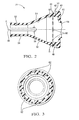
- Fig. 2 is an axial cross-section view of a grommet of the grommet assembly of Fig. 1 ;
- Fig. 3 is a radial cross-section view of the grommet of Fig. 2 taken through section line 3-3 of Fig. 1 ;
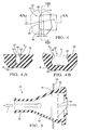
- Fig. 4 is an enlarged view of a portion of the interior of the grommet of Fig. 2 ;
- Figs. 4A and 4B are cross-section views of the portion shown in Fig. 4 taken through section lines 4A and 4B respectively;
- Fig. 5 is an axial cross-section view of the grommet of Fig. 1 being inserted into a hole of a panel;
- Fig. 6 is the enlarged view shown in Fig. 4 in the condition when the grommet is in maximum interference with the hole of the panel of Fig. 5 ;
- Figs. 6A and 6B are cross-section views of the portion shown in Fig. 4 taken through section lines 6A and 6B respectively;
- Fig. 7 is the axial cross-section view of Fig. 5 with the grommet fully inserted into the hole of the panel.
- Fig. 1 is a side view of a grommet assembly 10 extending along an axis A for passing a body, shown as wire 12, from a first compartment 14 to a second compartment 16.
- Grommet assembly 10 may be molded as a single piece using a flexible elastomer material.
- First compartment 14 may be, for example only, a body of a motor vehicle (not shown) while second compartment 16 may be, for example only, a door of the motor vehicle.
- Grommet assembly 10 includes a grommet 18 for passage through a panel 20 of first compartment 14, a grommet 22 for passage through a panel 24 of second compartment 16, and a connecting conduit 26 connecting grommet 18 to grommet 22.
- Connecting conduit 26 may have a connecting conduit sidewall 28 including a plurality of pleats 30 comprising alternating peaks and valleys.
- Pleats 30 allow for flexibility of connecting conduit 26, thereby allowing relative movement between first compartment 14 and second compartment 16, for example only, as when a door of a motor vehicle is opened and closed.
- Fig. 2 is an axial cross-section view of grommet 22.
- Fig. 3 is a radial cross-section view of grommet 22 through section line 3-3 as shown in Fig. 1 .
- Grommet 22 includes a funnel-shaped section 32 which is inclined with respect to axis A. Funnel-shaped section 32 is terminated at its small-diameter end by a tubular section 34 which extends axially away from funnel-shaped section 32 substantially parallel to axis A and terminates one end of grommet 22.
- Tubular section 34 may include axially extending notches 36 (only one is visible in Fig.
- Notches 36 may extend into funnel-shapes section 32 and may terminate in circular regions 38 which may have a diameter larger than the width of notches 36.
- Funnel-shaped section 32 extends to a circular ridgeline 40 which is at the large-diameter end of funnel-shaped section 32 and opposite of tubular section 34.
- Ridgeline 40 is sized to be larger in diameter than a hole 44 (shown in Fig. 1 ) of panel 24 through which grommet 22 passes.
- a first mounting flange 42 is located adjacent to ridgeline 40 and may be inclined with respect to axis A. As shown, first mounting flange 42 tapers from a maximum diameter that is proximal to ridgeline 40 to a minimum diameter that is distal from ridgeline 40.
- Grommet 22 is terminated at a second end, which is opposite of tubular section 34, by a second mounting flange 46 which is larger in diameter than hole 44 and which may be larger in diameter than ridgeline 40.
- First mounting flange 42 may extend, as shown, to second mounting flange 46.
- the region between first mounting flange 42 and second mounting flange 46 defines a mounting groove 48.
- Panel 24 is disposed in mounting groove 48 when grommet 22 is installed through panel 24, and grommet 22 is held securely in place by first mounting flange 42 and second mounting flange 46.
- the floor of mounting groove 48 i.e. where first mounting flange 42 meets second mounting flange 46, may be sized to have a free state diameter, i.e.
- second mounting flange 46 may include a sealing lip 50 extending axially away from second mounting flange 46 toward first mounting flange 42 to aid in sealing against panel 24 when grommet 22 is installed through panel 24.
- Grommet 22 is hollow to allow passage of wire 12 therethrough.
- the hollow nature of grommet 22 is defined in part by a tubular section inside diameter 52 which extends coaxially through tubular section 34.
- the hollow nature of grommet 22 is also defined in by part by an inclined interior surface 54 which extends over a portion of the interior of funnel-shaped section 32.
- the transition from tubular section inside diameter 52 to inclined interior surface 54 may be defined by a radius.
- Inclined interior surface 54 may be inclined with respect to axis A such that the portion of grommet 22 that includes inclined interior surface 54 has a substantially uniform wall thickness.
- the hollow nature of grommet 22 is also defined in part by a tubular inside section 56, a portion of which is axially aligned with ridgeline 40.
- Tubular inside section 56 is parallel and concentric with axis A.
- the transition from inclined interior surface 54 to tubular inside section 56 may be defined by a radius.
- the hollow nature of grommet 22 is also defined in part by a passage 58 which provides communication from the interior of grommet 22 to the interior of connecting conduit 26 (shown in Fig. 1 ). Passage 58 may be smaller in diameter than tubular inside section 56 as shown.
- the transition from tubular inside section 56 to passage 58 may be defined by an annular wall 60 and a pair of radii.
- an array of recesses 62 is provided on tubular inside section 56.
- Recesses 62 are centered about a centerline B which lies on a circle on tubular inside section 56 and which is perpendicular to axis A. Recesses 62 may each be equal is size and spaced evenly around tubular inside section 56. At least a portion of each recess 62 is preferably axially aligned with ridgeline 40 and even more preferably centerline B may be axially aligned with ridgeline 40.
- recesses 62 may be axially aligned with ridgeline 40 and recesses 62 are radially inward of a portion of funnel shaped section 32 that interferes with hole 44 during insertion. As shown (best shown in Fig. 3 ), there are 12 recesses 62. However, it should be understood that other numbers of recesses 62 may also be used depending on performance requirements of grommet 22.
- Fig. 4 is an enlarged view of one of recesses 62 as shown in Fig. 2 and Figs 4A and 4B are cross-section views through recess 62.
- Each recess 62 may be substantially oval or racetrack shaped.
- each recess 62 includes opposing sidewalls 64 that are parallel to centerline B and which are connected at each end by endwalls 66 that are arcuate, or curved, in shape. Sidewalls 64 and endwalls 66 together form a continuous wall defining each recess 64.
- Each recess has a length L 1 along centerline B and a width W 1 perpendicular to centerline B when grommet 22 is in the free state. It may be desirable that the sum of lengths L 1 of all recesses 62 be between about 30% and about 70% of the circumference of tubular inside section 56, even more preferably between about 40% and about 60% of the circumference of tubular inside section 56, and still even more preferably about 50% of the circumference of tubular inside section 56.
- Sidewalls 64 and endwalls 66 extend into grommet 22 and truncate at a recess floor 68.
- a radius R 1 may form the transition from sidewalls 64 and endwalls 66 to recess floor 68 while a radius R 2 may form the transition from tubular inside section 56 to sidewalls 64 and endwalls 66.
- FIG. 5 shows grommet 22 being inserted into hole 44 of panel 24.
- FIG. 6 is an enlarged view of one of recesses 62 when grommet 22 is partially inserted into hole 44 and Figs. 6A and 6B are cross-section views through recess 62 of Fig. 6 .
- Grommet 22 is inserted into hole 44 by a pulling force in the direction of arrow I as shown in Fig. 5 .
- tubular section 34 is the first portion of grommet 22 to pass through hole 44.
- Grommet 22 passes through hole 44 uninhibited until grommet 22 is inserted to a point at which funnel shaped section 32 is the same diameter as hole 44 as shown in Fig. 5 . From this point until panel 24 reaches ridgeline 40, the insertion force increases due to the increasing interference between hole 44 and grommet 22 as the result of the inclined nature of funnel-shaped section 32, thereby compressing funnel-shaped section 32. However, the inclusion of recesses 62 limits the insertion force. As panel 24 proceeds toward and finally reaches ridgeline 40, recess floor 68 of each recess 62 is pushed radially inward toward axis A.
- each recess 62 is allowed to expand such as to increase the perimeter of recess 62 where it meets tubular inside section 56 as shown in Fig. 6 .
- each recess 62 expands to a width W 2 that is greater than width W 1 in the free state ( Fig. 4 ).
- Each recess 62 may also expand to a length L 2 that is greater than length L 1 in the free state ( Fig. 4 ), however, the expansion in width is more pronounced that the expansion in length.
- sidewalls 64 and endwalls 66 angulate outward from each other as a result of this process.
- Figs. 6, 6A, and 6B also include phantom lines which represent the shape of recess 62 in the free state.
- FIG. 7 shows grommet 22 completely inserted into hole 44 of panel 24.
- panel 24 passes over ridgeline 40 as grommet 22 is pulled in the direction of arrow I, panel 24 descends first mounting flange 42. As this occurs, funnel-shaped section 32 expands and each recess 62 rebounds or contracts to the free state shape shown in Figs. 4, 4A, and 4B .
- Grommet 22 is now securely held by panel 24 within mounting groove 48.
- grommet 22 which includes recesses 62 for reducing the insertion force of grommet 22, has been described as a part of grommet assembly 10, it should now be understood that grommet 22 does not need to be used with grommet 18 and connecting conduit 26. For example, grommet 22 may be used alone for passing wire 12 through panel 24.
Landscapes
- Engineering & Computer Science (AREA)
- Architecture (AREA)
- Civil Engineering (AREA)
- Structural Engineering (AREA)
- Mechanical Engineering (AREA)
- Installation Of Indoor Wiring (AREA)
- Insulating Bodies (AREA)
Abstract
Description
- The present invention relates to a grommet, more particularly to a grommet that is insertable through a hole in a panel for passing a member therethrough, even more particularly to such a grommet for passing a wire or wiring harness therethrough, and still even more particularly to such a grommet with a reduced insertion force needed for inserting the grommet through the hole in the panel.
- Grommets that are insertable through a hole in panel are well known. Such grommets typically include an opening therethrough to allow passage of a body, for example a wire or wiring harness, through the grommet, and consequently through the panel. It may be desirable to minimize the force required, i.e. insertion force, to insert the grommet through the hole of the panel. At the same time, it is also may also be desirable to maintain a force required to remove the grommet from the hole, i.e. pull-out force, which may typically be substantially higher than the insertion force to securely retain the grommet within the hole after installation. In one example, a maximum insertion force of 40N may be desired while minimum a pull-out force of 100N may be desired. More generally it may be desirable for the grommet to have pull-out force that is at least 1.5 times the insertion force.
- One way to decrease the insertion force of the grommet is to apply a lubricant to the exterior surface thereof to reduce friction between the exterior surface of the grommet and the hole of the panel. While this method may be effective, the lubricant may be messy or may not be compatible with insulation used on the wire which passes through the grommet. Some lubricants may not provide the desired benefit because they may dissipate too quickly to be beneficial.
- Another way to decrease the insertion force of the grommet is by the design or geometry of the grommet. In one design to decrease insertion force, thick ribs may be placed on the outside surface of the grommet which contacts the hole during insertion of the grommet. This creates localized points of contact, which in turn leads to less friction during insertion of the grommet. However, the thick ribs add material and therefore mass and cost to the grommet.
- In another design, shown in
US Patent Application Publication No. 2005/0139381 , a series of relief grooves are placed on the internal surface of the grommet. These relief grooves extend to the end of the grommet and are so placed to decrease the insertion force of the grommet. However, the nature of the relief grooves allows the relief grooves to contract during insertion of the grommet, thereby minimizing the benefit of the relief grooves. - What is needed is a grommet which minimizes or eliminates one or more of the shortcomings as set forth above, what is also needed is such a grommet which reduces the insertion force of the grommet.
- The invention consists on a grommet extending along an axis for insertion into a hole of a panel. The grommet includes a hollow funnel-shaped section inclined to the axis such that a portion of the funnel-shaped section is compressed radially inward during insertion of the grommet into the hole, the funnel-shaped section terminating at a circular ridgeline. The grommet also includes a retention groove adjacent to the ridgeline, for receiving the panel upon complete insertion of the grommet into the hole. An array of recesses is included on an inside surface, parallel to the axis, of the grommet. The recesses are arranged to expand when the funnel-shaped section passes through the hole during insertion of the grommet into the hole. Each recess is centered about a centerline lying on a circle that is perpendicular to the axis, the centerline being axially aligned with the ridgeline. Each recess has a pair of opposing sidewalls arcuate in shape that are connected at each end by endwalls, the opposing sidewalls being parallel to the centerline. In order to reduce the insertion force of the grommet, each recess has a first width in the direction of the axis when the grommet is in a free state, and each recess expands to a second width greater than the first width when the funnel-shaped section passes through the hole during insertion of the grommet into the hole. Each recess returns to the first width when the panel is received within the retention groove. Each recess defined by a continuous wall, has a length along the centerline in the free state, the length being greater than the first width.
- In accordance with another aspect of the present invention, a method for inserting a grommet into a hole of a panel is provided. The method includes a step of providing the grommet, the grommet extending along an axis and including a hollow funnel-shaped section inclined to the axis and terminating at a circular ridgeline, a retention groove adjacent to the ridgeline and an array of recesses on an inside surface of the grommet. The method also includes a step of passing the funnel shaped section through said hole, such that the funnel shaped section is compressed radially inward. The method also includes a step of expanding the recesses when the funnel shaped section is compressed radially inward. The method further includes a step of receiving the panel within the retention groove after expanding said recesses. The method still further includes a step of expanding the funnel shaped section as the panel is received within the retention groove. The method further includes the last step of contracting the recesses as the funnel shaped section is expands.
- This invention will be further described with reference to the accompanying drawings in which:
-
Fig. 1 is an elevation view of a grommet assembly in accordance with the present invention; -
Fig. 2 is an axial cross-section view of a grommet of the grommet assembly ofFig. 1 ; -
Fig. 3 is a radial cross-section view of the grommet ofFig. 2 taken through section line 3-3 ofFig. 1 ; -
Fig. 4 is an enlarged view of a portion of the interior of the grommet ofFig. 2 ; -
Figs. 4A and 4B are cross-section views of the portion shown inFig. 4 taken throughsection lines -
Fig. 5 is an axial cross-section view of the grommet ofFig. 1 being inserted into a hole of a panel; -
Fig. 6 is the enlarged view shown inFig. 4 in the condition when the grommet is in maximum interference with the hole of the panel ofFig. 5 ; -
Figs. 6A and 6B are cross-section views of the portion shown inFig. 4 taken throughsection lines -
Fig. 7 is the axial cross-section view ofFig. 5 with the grommet fully inserted into the hole of the panel. - Referring now to the drawings wherein like reference numerals are used to identify identical components in the various views,
Fig. 1 is a side view of agrommet assembly 10 extending along an axis A for passing a body, shown aswire 12, from afirst compartment 14 to asecond compartment 16.Grommet assembly 10 may be molded as a single piece using a flexible elastomer material.First compartment 14 may be, for example only, a body of a motor vehicle (not shown) whilesecond compartment 16 may be, for example only, a door of the motor vehicle. Grommetassembly 10 includes agrommet 18 for passage through apanel 20 offirst compartment 14, agrommet 22 for passage through apanel 24 ofsecond compartment 16, and a connectingconduit 26 connectinggrommet 18 to grommet 22. Connectingconduit 26 may have a connectingconduit sidewall 28 including a plurality ofpleats 30 comprising alternating peaks and valleys.Pleats 30 allow for flexibility of connectingconduit 26, thereby allowing relative movement betweenfirst compartment 14 andsecond compartment 16, for example only, as when a door of a motor vehicle is opened and closed. - Reference will now be made to
Fig. 2 which is an axial cross-section view ofgrommet 22. Reference will also be made toFig. 3 which is a radial cross-section view ofgrommet 22 through section line 3-3 as shown inFig. 1 . Grommet 22 includes a funnel-shaped section 32 which is inclined with respect to axis A. Funnel-shaped section 32 is terminated at its small-diameter end by atubular section 34 which extends axially away from funnel-shaped section 32 substantially parallel to axis A and terminates one end ofgrommet 22.Tubular section 34 may include axially extending notches 36 (only one is visible inFig. 2 ) to permit, for example only, an electrical connector (not shown) of wire 12 (shown inFig. 1 ) to be easily passed throughtubular section 34.Notches 36 may extend into funnel-shapes section 32 and may terminate incircular regions 38 which may have a diameter larger than the width ofnotches 36. - Funnel-
shaped section 32 extends to acircular ridgeline 40 which is at the large-diameter end of funnel-shaped section 32 and opposite oftubular section 34. Ridgeline 40 is sized to be larger in diameter than a hole 44 (shown inFig. 1 ) ofpanel 24 through which grommet 22 passes. - A
first mounting flange 42 is located adjacent toridgeline 40 and may be inclined with respect to axis A. As shown,first mounting flange 42 tapers from a maximum diameter that is proximal toridgeline 40 to a minimum diameter that is distal fromridgeline 40. -
Grommet 22 is terminated at a second end, which is opposite oftubular section 34, by a second mountingflange 46 which is larger in diameter thanhole 44 and which may be larger in diameter thanridgeline 40. First mountingflange 42 may extend, as shown, to second mountingflange 46. The region between first mountingflange 42 and second mountingflange 46 defines a mountinggroove 48.Panel 24 is disposed in mountinggroove 48 whengrommet 22 is installed throughpanel 24, andgrommet 22 is held securely in place by first mountingflange 42 and second mountingflange 46. The floor of mountinggroove 48, i.e. where first mountingflange 42 meets second mountingflange 46, may be sized to have a free state diameter, i.e. beforegrommet 22 is installed throughpanel 24, that is slightly larger than the inside diameter ofhole 44. For example only, the free state diameter of the floor of mountinggroove 48 may be 1mm larger than the diameter ofhole 44. This allows for a compressive force between the floor of mountinggroove 48 andhole 44 to aid in sealing. As shown, second mountingflange 46 may include a sealinglip 50 extending axially away from second mountingflange 46 toward first mountingflange 42 to aid in sealing againstpanel 24 whengrommet 22 is installed throughpanel 24. - With the exterior features of
grommet 22 having been described, discussion now will turn to the interior features ofgrommet 22 with continued reference toFigs. 2 and 3 .Grommet 22 is hollow to allow passage ofwire 12 therethrough. The hollow nature ofgrommet 22 is defined in part by a tubular section insidediameter 52 which extends coaxially throughtubular section 34. The hollow nature ofgrommet 22 is also defined in by part by an inclinedinterior surface 54 which extends over a portion of the interior of funnel-shapedsection 32. The transition from tubular section insidediameter 52 to inclinedinterior surface 54 may be defined by a radius. Inclinedinterior surface 54 may be inclined with respect to axis A such that the portion ofgrommet 22 that includes inclinedinterior surface 54 has a substantially uniform wall thickness. The hollow nature ofgrommet 22 is also defined in part by a tubular insidesection 56, a portion of which is axially aligned withridgeline 40. Tubular insidesection 56 is parallel and concentric with axis A. The transition from inclinedinterior surface 54 to tubular insidesection 56 may be defined by a radius. The hollow nature ofgrommet 22 is also defined in part by apassage 58 which provides communication from the interior ofgrommet 22 to the interior of connecting conduit 26 (shown inFig. 1 ).Passage 58 may be smaller in diameter than tubularinside section 56 as shown. The transition from tubular insidesection 56 topassage 58 may be defined by anannular wall 60 and a pair of radii. - In order to reduce the insertion force of
grommet 22 intohole 44, an array ofrecesses 62 is provided on tubularinside section 56. For clarity, only some recesses have been labeled with thereference number 62; it should be understood that the identical, unnumbered features are also recesses 62.Recesses 62 are centered about a centerline B which lies on a circle on tubularinside section 56 and which is perpendicular to axis A. Recesses 62 may each be equal is size and spaced evenly around tubular insidesection 56. At least a portion of eachrecess 62 is preferably axially aligned withridgeline 40 and even more preferably centerline B may be axially aligned withridgeline 40. Alternatively, but not shown, no part ofrecesses 62 may be axially aligned withridgeline 40 and recesses 62 are radially inward of a portion of funnel shapedsection 32 that interferes withhole 44 during insertion. As shown (best shown inFig. 3 ), there are 12recesses 62. However, it should be understood that other numbers ofrecesses 62 may also be used depending on performance requirements ofgrommet 22. - Reference will now be made to
Figs. 4, 4A, and 4B in whichFig. 4 is an enlarged view of one ofrecesses 62 as shown inFig. 2 andFigs 4A and 4B are cross-section views throughrecess 62. Eachrecess 62 may be substantially oval or racetrack shaped. In this way, eachrecess 62 includes opposingsidewalls 64 that are parallel to centerline B and which are connected at each end by endwalls 66 that are arcuate, or curved, in shape. Sidewalls 64 and endwalls 66 together form a continuous wall defining eachrecess 64. Each recess has a length L1 along centerline B and a width W1 perpendicular to centerline B whengrommet 22 is in the free state. It may be desirable that the sum of lengths L1 of allrecesses 62 be between about 30% and about 70% of the circumference of tubularinside section 56, even more preferably between about 40% and about 60% of the circumference of tubularinside section 56, and still even more preferably about 50% of the circumference of tubularinside section 56. Sidewalls 64 and endwalls 66 extend intogrommet 22 and truncate at arecess floor 68. A radius R1 may form the transition from sidewalls 64 and endwalls 66 to recessfloor 68 while a radius R2 may form the transition from tubular insidesection 56 to sidewalls 64 andendwalls 66. - Reference will now be made to
Fig. 5 which showsgrommet 22 being inserted intohole 44 ofpanel 24. Reference will also be made toFigs. 6, 6A, and 6B in whichFig. 6 is an enlarged view of one ofrecesses 62 whengrommet 22 is partially inserted intohole 44 andFigs. 6A and 6B are cross-section views throughrecess 62 ofFig. 6 .Grommet 22 is inserted intohole 44 by a pulling force in the direction of arrow I as shown inFig. 5 . In this way,tubular section 34 is the first portion ofgrommet 22 to pass throughhole 44.Grommet 22 passes throughhole 44 uninhibited untilgrommet 22 is inserted to a point at which funnel shapedsection 32 is the same diameter ashole 44 as shown inFig. 5 . From this point untilpanel 24 reaches ridgeline 40, the insertion force increases due to the increasing interference betweenhole 44 andgrommet 22 as the result of the inclined nature of funnel-shapedsection 32, thereby compressing funnel-shapedsection 32. However, the inclusion ofrecesses 62 limits the insertion force. Aspanel 24 proceeds toward and finally reachesridgeline 40,recess floor 68 of eachrecess 62 is pushed radially inward toward axis A. When this occurs, eachrecess 62 is allowed to expand such as to increase the perimeter ofrecess 62 where it meets tubularinside section 56 as shown inFig. 6 . In this way, eachrecess 62 expands to a width W2 that is greater than width W1 in the free state (Fig. 4 ). Eachrecess 62 may also expand to a length L2 that is greater than length L1 in the free state (Fig. 4 ), however, the expansion in width is more pronounced that the expansion in length. As can be seen inFigs. 6A and 6B , sidewalls 64 andendwalls 66 angulate outward from each other as a result of this process. For comparison purposes,Figs. 6, 6A, and 6B also include phantom lines which represent the shape ofrecess 62 in the free state. - Reference will now be made to
Fig. 7 which showsgrommet 22 completely inserted intohole 44 ofpanel 24. Whenpanel 24 passes overridgeline 40 asgrommet 22 is pulled in the direction of arrow I,panel 24 descends first mountingflange 42. As this occurs, funnel-shapedsection 32 expands and eachrecess 62 rebounds or contracts to the free state shape shown inFigs. 4, 4A, and 4B .Grommet 22 is now securely held bypanel 24 within mountinggroove 48. - While
grommet 22, which includesrecesses 62 for reducing the insertion force ofgrommet 22, has been described as a part ofgrommet assembly 10, it should now be understood thatgrommet 22 does not need to be used withgrommet 18 and connectingconduit 26. For example,grommet 22 may be used alone for passingwire 12 throughpanel 24. - While this invention has been described in terms of preferred embodiments thereof, it is not intended to be so limited, but rather only to the extent set forth in the claims that follow.
Claims (14)
- A grommet (22) extending along an axis (A) for insertion into a hole (44) of a panel (24), said grommet (22) comprising:a hollow funnel-shaped section (32) inclined to said axis (A) such that a portion of said funnel-shaped section (32) is compressed radially inward during insertion of said grommet (22) into said hole (44), said funnel-shaped section (32) terminating at a circular ridgeline (40);a retention groove (48) adjacent to said ridgeline (40), said retention groove (48) receiving said panel (24) upon complete insertion of said grommet (22) into said hole (44);an array of recesses (62) on an inside surface (56) of said grommet (22), said recesses (62) being arranged to expand when said funnel-shaped section (32) passes through said hole (44) during insertion of said grommet (22) into said hole (44).
- A grommet (22) as in claim 1, wherein each recess (62) is centered about a centerline (B) lying on a circle that is perpendicular to said axis (A).
- A grommet (22) as set in any of previous claims wherein each of said recesses (62) has a pair of opposing sidewalls (64) that are connected at each end by endwalls (66).
- A grommet (22) as set in any of previous claim wherein each recess (62) is defined by a continuous wall (64, 66).
- A grommet (22) as set in any of previous claims wherein said inside surface (56) is parallel to said axis (A).
- A grommet (22) as set in any of previous claims wherein each of said recesses (62) has a first width (W1) in the direction of said axis (A) when said grommet (22) is in a free state and wherein each of said recesses (62) expands to a second width (W2) that is greater than said first width (W1) when said funnel-shaped section (32) passes through said hole (44) during insertion of said grommet (22) into said hole (44), thereby reducing the insertion force of said grommet (22).
- A grommet (22) as in claim 6 wherein each of said recesses (62) returns to said first width (W1) when said panel (20) is received within said retention groove (48).
- A grommet (22) as set in any of preceding claims taken in combination with claim 2, wherein said centerline (B) is axially aligned with said ridgeline (40).
- A grommet (22) as set in the combination of claim 2 and claim 3 wherein said opposing sidewalls (64) are parallel to said centerline (B).
- A grommet (22) as set in any of the preceding claims taken in combination with claim 3 wherein said endwalls (66) are arcuate in shape.
- A grommet (22) as set in the combination of claim 2 and claim 6 wherein each of said recesses (62) has a length (L1) along said centerline (B) in said free state, wherein said length (L1) is greater than said first width (W1).
- A method for inserting a grommet (22) into a hole (44) of a panel (24), said method comprising:providing said grommet (22), said grommet (22) extending along an axis (A) and including a hollow funnel-shaped section (32) inclined to said axis (A) and terminating at a circular ridgeline (40), a retention groove (48) adjacent to said ridgeline (40), and an array of recesses (62) on an inside surface (56) of said grommet (22);passing said funnel shaped section (32) through said hole (44), thereby compressing said funnel shaped section (32) radially inward;expanding said recesses (62) when said funnel shaped section (32) is compressed radially inward;receiving said panel (20) within said retention groove (48) after expanding said recesses (62).
- A method as in claim 12, said method further comprising expanding said funnel shaped section (32) as said panel (20) is received within said retention groove (48).
- A method as in claim 12 or 13, said method further comprising contracting said recesses (62) as said funnel shaped section (32) expands.
Applications Claiming Priority (1)
| Application Number | Priority Date | Filing Date | Title |
|---|---|---|---|
| US13/465,066 US8584315B1 (en) | 2012-05-07 | 2012-05-07 | Grommet |
Publications (2)
| Publication Number | Publication Date |
|---|---|
| EP2662243A1 true EP2662243A1 (en) | 2013-11-13 |
| EP2662243B1 EP2662243B1 (en) | 2014-11-26 |
Family
ID=48288843
Family Applications (1)
| Application Number | Title | Priority Date | Filing Date |
|---|---|---|---|
| EP13166163.9A Active EP2662243B1 (en) | 2012-05-07 | 2013-05-02 | Grommet |
Country Status (3)
| Country | Link |
|---|---|
| US (1) | US8584315B1 (en) |
| EP (1) | EP2662243B1 (en) |
| JP (1) | JP6196464B2 (en) |
Families Citing this family (10)
| Publication number | Priority date | Publication date | Assignee | Title |
|---|---|---|---|---|
| US20150040345A1 (en) * | 2013-08-06 | 2015-02-12 | Honda Motor Co., Ltd. | Vehicle grommet and method |
| US9379530B2 (en) * | 2013-12-05 | 2016-06-28 | Delphi Technologies, Inc. | Grommet with spreader mounting feature |
| JP2017158232A (en) * | 2016-02-29 | 2017-09-07 | 住友電装株式会社 | Elastic tubular body |
| JP6854261B2 (en) * | 2018-06-22 | 2021-04-07 | 矢崎総業株式会社 | Grommet |
| JP7151584B2 (en) * | 2019-03-27 | 2022-10-12 | 住友電装株式会社 | Grommet |
| JP7110258B2 (en) * | 2020-02-18 | 2022-08-01 | 矢崎総業株式会社 | Grommet and wire harness |
| JP7133596B2 (en) * | 2020-09-10 | 2022-09-08 | 住友電装株式会社 | Grommet |
| JP7838941B2 (en) * | 2021-10-20 | 2026-04-01 | 矢崎総業株式会社 | Wire harness and grommet |
| JP7703145B2 (en) * | 2022-03-01 | 2025-07-07 | 株式会社オートネットワーク技術研究所 | Grommet |
| US20230304609A1 (en) * | 2022-03-25 | 2023-09-28 | Principal Lighting Group, Llc | Pass-through apparatus for wall mounted sign assembly |
Citations (4)
| Publication number | Priority date | Publication date | Assignee | Title |
|---|---|---|---|---|
| JPH07336068A (en) * | 1994-06-10 | 1995-12-22 | Sumitomo Wiring Syst Ltd | Grommet for wire harness |
| EP0798166A2 (en) * | 1996-03-29 | 1997-10-01 | Sumitomo Wiring Systems, Ltd. | Grommet and a method for mounting a grommet |
| US20050139381A1 (en) | 2005-01-21 | 2005-06-30 | Osram Sylvania Inc. | Low insertion force seating grommet |
| JP2008234946A (en) * | 2007-03-19 | 2008-10-02 | Furukawa Electric Co Ltd:The | Grommet |
Family Cites Families (16)
| Publication number | Priority date | Publication date | Assignee | Title |
|---|---|---|---|---|
| JPH0181820U (en) * | 1987-11-20 | 1989-05-31 | ||
| JPH0741881U (en) | 1993-12-27 | 1995-07-21 | 住友電装株式会社 | Grommet for wire harness |
| GB2289104B (en) * | 1994-04-21 | 1997-05-21 | Inoue Mtp Kk | Grommet |
| JPH09147649A (en) * | 1995-11-22 | 1997-06-06 | Yazaki Corp | Grommet |
| US5732440A (en) * | 1996-02-06 | 1998-03-31 | Osram Sylvania Inc. | Low insertion force grommet |
| JPH10302563A (en) * | 1997-04-22 | 1998-11-13 | Yazaki Corp | Grommet |
| JP3346413B2 (en) * | 2000-09-22 | 2002-11-18 | 住友電装株式会社 | Grommet |
| US6495767B2 (en) * | 2000-09-22 | 2002-12-17 | Sumitomo Wiring Systems, Ltd. | Grommet |
| EP1473195B8 (en) * | 2000-09-22 | 2007-02-21 | Sumitomo Wiring Systems, Ltd. | Grommet |
| US6486400B1 (en) | 2001-09-18 | 2002-11-26 | Delphi Technologies, Inc. | Acoustic grommet |
| JP3918486B2 (en) * | 2001-09-28 | 2007-05-23 | 住友電装株式会社 | Grommet |
| JP4036135B2 (en) | 2003-04-18 | 2008-01-23 | 住友電装株式会社 | Grommet |
| JP4412148B2 (en) * | 2004-10-26 | 2010-02-10 | 住友電装株式会社 | Grommet |
| JP4406374B2 (en) * | 2005-01-07 | 2010-01-27 | 矢崎総業株式会社 | Grommet assembly assembly structure |
| US7026549B1 (en) * | 2005-02-04 | 2006-04-11 | Delphi Technologies, Inc. | Collapsible grommet |
| DE102006042663A1 (en) * | 2006-09-12 | 2008-03-27 | Robert Bosch Gmbh | Fastening device for a line |
-
2012
- 2012-05-07 US US13/465,066 patent/US8584315B1/en active Active
-
2013
- 2013-05-01 JP JP2013096223A patent/JP6196464B2/en active Active
- 2013-05-02 EP EP13166163.9A patent/EP2662243B1/en active Active
Patent Citations (4)
| Publication number | Priority date | Publication date | Assignee | Title |
|---|---|---|---|---|
| JPH07336068A (en) * | 1994-06-10 | 1995-12-22 | Sumitomo Wiring Syst Ltd | Grommet for wire harness |
| EP0798166A2 (en) * | 1996-03-29 | 1997-10-01 | Sumitomo Wiring Systems, Ltd. | Grommet and a method for mounting a grommet |
| US20050139381A1 (en) | 2005-01-21 | 2005-06-30 | Osram Sylvania Inc. | Low insertion force seating grommet |
| JP2008234946A (en) * | 2007-03-19 | 2008-10-02 | Furukawa Electric Co Ltd:The | Grommet |
Also Published As
| Publication number | Publication date |
|---|---|
| JP6196464B2 (en) | 2017-09-13 |
| JP2013236536A (en) | 2013-11-21 |
| EP2662243B1 (en) | 2014-11-26 |
| US8584315B1 (en) | 2013-11-19 |
| US20130291335A1 (en) | 2013-11-07 |
Similar Documents
| Publication | Publication Date | Title |
|---|---|---|
| EP2662243B1 (en) | Grommet | |
| US8981228B2 (en) | Grommet for wire harness | |
| CA2747792C (en) | Grommet | |
| EP2425509B1 (en) | Cold-shrink separable connector | |
| US7683265B2 (en) | Grommet and forming method for the grommet | |
| US8108968B2 (en) | Grommet assembly | |
| US6049960A (en) | Method and device for sliding and positioning sleeve-shaped elastic components on cylindrical or conical base bodies | |
| EP2703705A1 (en) | Sealing system for an annular space | |
| CN113346430B (en) | Grommet and wire harness | |
| US11592050B2 (en) | Apparatus for a captured fastener assembly with expanding grommet | |
| JP2007524213A (en) | Core for cable inlet device | |
| EP3413404A1 (en) | Sealed electrical connector assembly and wire seal | |
| US5414218A (en) | Arrangement for cable tensile strain relief | |
| CN109314381A (en) | Wire grommets and wire harnesses | |
| EP3526867B1 (en) | Cable gland comprising a slip on grommet | |
| EP2847839B1 (en) | Wire harness waterproofing structure | |
| US5199320A (en) | Remote control assembly with conduit anchor device | |
| CN113270831B (en) | Grommet and wire harness | |
| US20230387673A1 (en) | Cable gland | |
| US7568944B1 (en) | Compression connector for a coaxial cable | |
| US20180102614A1 (en) | Pass-thru connector assembly and apparatus having the same | |
| CN208587379U (en) | Hole clamp spring and shell | |
| EP2999057A1 (en) | Seal | |
| CN113270832B (en) | Grommets and Harnesses | |
| US7257889B1 (en) | Method for inserting wires through braided shielding |
Legal Events
| Date | Code | Title | Description |
|---|---|---|---|
| PUAI | Public reference made under article 153(3) epc to a published international application that has entered the european phase |
Free format text: ORIGINAL CODE: 0009012 |
|
| AK | Designated contracting states |
Kind code of ref document: A1 Designated state(s): AL AT BE BG CH CY CZ DE DK EE ES FI FR GB GR HR HU IE IS IT LI LT LU LV MC MK MT NL NO PL PT RO RS SE SI SK SM TR |
|
| AX | Request for extension of the european patent |
Extension state: BA ME |
|
| 17P | Request for examination filed |
Effective date: 20140513 |
|
| RBV | Designated contracting states (corrected) |
Designated state(s): AL AT BE BG CH CY CZ DE DK EE ES FI FR GB GR HR HU IE IS IT LI LT LU LV MC MK MT NL NO PL PT RO RS SE SI SK SM TR |
|
| GRAP | Despatch of communication of intention to grant a patent |
Free format text: ORIGINAL CODE: EPIDOSNIGR1 |
|
| INTG | Intention to grant announced |
Effective date: 20140707 |
|
| GRAS | Grant fee paid |
Free format text: ORIGINAL CODE: EPIDOSNIGR3 |
|
| GRAA | (expected) grant |
Free format text: ORIGINAL CODE: 0009210 |
|
| AK | Designated contracting states |
Kind code of ref document: B1 Designated state(s): AL AT BE BG CH CY CZ DE DK EE ES FI FR GB GR HR HU IE IS IT LI LT LU LV MC MK MT NL NO PL PT RO RS SE SI SK SM TR |
|
| REG | Reference to a national code |
Ref country code: GB Ref legal event code: FG4D |
|
| REG | Reference to a national code |
Ref country code: CH Ref legal event code: EP |
|
| REG | Reference to a national code |
Ref country code: AT Ref legal event code: REF Ref document number: 697972 Country of ref document: AT Kind code of ref document: T Effective date: 20141215 |
|
| REG | Reference to a national code |
Ref country code: IE Ref legal event code: FG4D |
|
| REG | Reference to a national code |
Ref country code: DE Ref legal event code: R096 Ref document number: 602013000524 Country of ref document: DE Effective date: 20150108 |
|
| REG | Reference to a national code |
Ref country code: NL Ref legal event code: VDEP Effective date: 20141126 |
|
| REG | Reference to a national code |
Ref country code: AT Ref legal event code: MK05 Ref document number: 697972 Country of ref document: AT Kind code of ref document: T Effective date: 20141126 |
|
| REG | Reference to a national code |
Ref country code: LT Ref legal event code: MG4D |
|
| PG25 | Lapsed in a contracting state [announced via postgrant information from national office to epo] |
Ref country code: IS Free format text: LAPSE BECAUSE OF FAILURE TO SUBMIT A TRANSLATION OF THE DESCRIPTION OR TO PAY THE FEE WITHIN THE PRESCRIBED TIME-LIMIT Effective date: 20150326 Ref country code: ES Free format text: LAPSE BECAUSE OF FAILURE TO SUBMIT A TRANSLATION OF THE DESCRIPTION OR TO PAY THE FEE WITHIN THE PRESCRIBED TIME-LIMIT Effective date: 20141126 Ref country code: PT Free format text: LAPSE BECAUSE OF FAILURE TO SUBMIT A TRANSLATION OF THE DESCRIPTION OR TO PAY THE FEE WITHIN THE PRESCRIBED TIME-LIMIT Effective date: 20150326 Ref country code: NO Free format text: LAPSE BECAUSE OF FAILURE TO SUBMIT A TRANSLATION OF THE DESCRIPTION OR TO PAY THE FEE WITHIN THE PRESCRIBED TIME-LIMIT Effective date: 20150226 Ref country code: FI Free format text: LAPSE BECAUSE OF FAILURE TO SUBMIT A TRANSLATION OF THE DESCRIPTION OR TO PAY THE FEE WITHIN THE PRESCRIBED TIME-LIMIT Effective date: 20141126 Ref country code: NL Free format text: LAPSE BECAUSE OF FAILURE TO SUBMIT A TRANSLATION OF THE DESCRIPTION OR TO PAY THE FEE WITHIN THE PRESCRIBED TIME-LIMIT Effective date: 20141126 Ref country code: LT Free format text: LAPSE BECAUSE OF FAILURE TO SUBMIT A TRANSLATION OF THE DESCRIPTION OR TO PAY THE FEE WITHIN THE PRESCRIBED TIME-LIMIT Effective date: 20141126 |
|
| REG | Reference to a national code |
Ref country code: FR Ref legal event code: PLFP Year of fee payment: 3 |
|
| PG25 | Lapsed in a contracting state [announced via postgrant information from national office to epo] |
Ref country code: GR Free format text: LAPSE BECAUSE OF FAILURE TO SUBMIT A TRANSLATION OF THE DESCRIPTION OR TO PAY THE FEE WITHIN THE PRESCRIBED TIME-LIMIT Effective date: 20150227 Ref country code: RS Free format text: LAPSE BECAUSE OF FAILURE TO SUBMIT A TRANSLATION OF THE DESCRIPTION OR TO PAY THE FEE WITHIN THE PRESCRIBED TIME-LIMIT Effective date: 20141126 Ref country code: HR Free format text: LAPSE BECAUSE OF FAILURE TO SUBMIT A TRANSLATION OF THE DESCRIPTION OR TO PAY THE FEE WITHIN THE PRESCRIBED TIME-LIMIT Effective date: 20141126 Ref country code: CY Free format text: LAPSE BECAUSE OF FAILURE TO SUBMIT A TRANSLATION OF THE DESCRIPTION OR TO PAY THE FEE WITHIN THE PRESCRIBED TIME-LIMIT Effective date: 20141126 Ref country code: SE Free format text: LAPSE BECAUSE OF FAILURE TO SUBMIT A TRANSLATION OF THE DESCRIPTION OR TO PAY THE FEE WITHIN THE PRESCRIBED TIME-LIMIT Effective date: 20141126 Ref country code: LV Free format text: LAPSE BECAUSE OF FAILURE TO SUBMIT A TRANSLATION OF THE DESCRIPTION OR TO PAY THE FEE WITHIN THE PRESCRIBED TIME-LIMIT Effective date: 20141126 Ref country code: AT Free format text: LAPSE BECAUSE OF FAILURE TO SUBMIT A TRANSLATION OF THE DESCRIPTION OR TO PAY THE FEE WITHIN THE PRESCRIBED TIME-LIMIT Effective date: 20141126 |
|
| PG25 | Lapsed in a contracting state [announced via postgrant information from national office to epo] |
Ref country code: CZ Free format text: LAPSE BECAUSE OF FAILURE TO SUBMIT A TRANSLATION OF THE DESCRIPTION OR TO PAY THE FEE WITHIN THE PRESCRIBED TIME-LIMIT Effective date: 20141126 Ref country code: SK Free format text: LAPSE BECAUSE OF FAILURE TO SUBMIT A TRANSLATION OF THE DESCRIPTION OR TO PAY THE FEE WITHIN THE PRESCRIBED TIME-LIMIT Effective date: 20141126 Ref country code: EE Free format text: LAPSE BECAUSE OF FAILURE TO SUBMIT A TRANSLATION OF THE DESCRIPTION OR TO PAY THE FEE WITHIN THE PRESCRIBED TIME-LIMIT Effective date: 20141126 Ref country code: RO Free format text: LAPSE BECAUSE OF FAILURE TO SUBMIT A TRANSLATION OF THE DESCRIPTION OR TO PAY THE FEE WITHIN THE PRESCRIBED TIME-LIMIT Effective date: 20141126 Ref country code: DK Free format text: LAPSE BECAUSE OF FAILURE TO SUBMIT A TRANSLATION OF THE DESCRIPTION OR TO PAY THE FEE WITHIN THE PRESCRIBED TIME-LIMIT Effective date: 20141126 |
|
| REG | Reference to a national code |
Ref country code: DE Ref legal event code: R097 Ref document number: 602013000524 Country of ref document: DE |
|
| PG25 | Lapsed in a contracting state [announced via postgrant information from national office to epo] |
Ref country code: PL Free format text: LAPSE BECAUSE OF FAILURE TO SUBMIT A TRANSLATION OF THE DESCRIPTION OR TO PAY THE FEE WITHIN THE PRESCRIBED TIME-LIMIT Effective date: 20141126 |
|
| PLBE | No opposition filed within time limit |
Free format text: ORIGINAL CODE: 0009261 |
|
| STAA | Information on the status of an ep patent application or granted ep patent |
Free format text: STATUS: NO OPPOSITION FILED WITHIN TIME LIMIT |
|
| 26N | No opposition filed |
Effective date: 20150827 |
|
| PG25 | Lapsed in a contracting state [announced via postgrant information from national office to epo] |
Ref country code: MC Free format text: LAPSE BECAUSE OF FAILURE TO SUBMIT A TRANSLATION OF THE DESCRIPTION OR TO PAY THE FEE WITHIN THE PRESCRIBED TIME-LIMIT Effective date: 20141126 Ref country code: LU Free format text: LAPSE BECAUSE OF FAILURE TO SUBMIT A TRANSLATION OF THE DESCRIPTION OR TO PAY THE FEE WITHIN THE PRESCRIBED TIME-LIMIT Effective date: 20150502 |
|
| REG | Reference to a national code |
Ref country code: IE Ref legal event code: MM4A |
|
| PG25 | Lapsed in a contracting state [announced via postgrant information from national office to epo] |
Ref country code: SI Free format text: LAPSE BECAUSE OF FAILURE TO SUBMIT A TRANSLATION OF THE DESCRIPTION OR TO PAY THE FEE WITHIN THE PRESCRIBED TIME-LIMIT Effective date: 20141126 |
|
| PG25 | Lapsed in a contracting state [announced via postgrant information from national office to epo] |
Ref country code: IE Free format text: LAPSE BECAUSE OF NON-PAYMENT OF DUE FEES Effective date: 20150502 |
|
| REG | Reference to a national code |
Ref country code: FR Ref legal event code: PLFP Year of fee payment: 4 |
|
| PG25 | Lapsed in a contracting state [announced via postgrant information from national office to epo] |
Ref country code: MT Free format text: LAPSE BECAUSE OF FAILURE TO SUBMIT A TRANSLATION OF THE DESCRIPTION OR TO PAY THE FEE WITHIN THE PRESCRIBED TIME-LIMIT Effective date: 20141126 |
|
| REG | Reference to a national code |
Ref country code: CH Ref legal event code: PL |
|
| PG25 | Lapsed in a contracting state [announced via postgrant information from national office to epo] |
Ref country code: LI Free format text: LAPSE BECAUSE OF NON-PAYMENT OF DUE FEES Effective date: 20160531 Ref country code: CH Free format text: LAPSE BECAUSE OF NON-PAYMENT OF DUE FEES Effective date: 20160531 |
|
| REG | Reference to a national code |
Ref country code: FR Ref legal event code: PLFP Year of fee payment: 5 |
|
| PG25 | Lapsed in a contracting state [announced via postgrant information from national office to epo] |
Ref country code: HU Free format text: LAPSE BECAUSE OF FAILURE TO SUBMIT A TRANSLATION OF THE DESCRIPTION OR TO PAY THE FEE WITHIN THE PRESCRIBED TIME-LIMIT; INVALID AB INITIO Effective date: 20130502 Ref country code: BG Free format text: LAPSE BECAUSE OF FAILURE TO SUBMIT A TRANSLATION OF THE DESCRIPTION OR TO PAY THE FEE WITHIN THE PRESCRIBED TIME-LIMIT Effective date: 20141126 |
|
| PG25 | Lapsed in a contracting state [announced via postgrant information from national office to epo] |
Ref country code: TR Free format text: LAPSE BECAUSE OF FAILURE TO SUBMIT A TRANSLATION OF THE DESCRIPTION OR TO PAY THE FEE WITHIN THE PRESCRIBED TIME-LIMIT Effective date: 20141126 |
|
| PG25 | Lapsed in a contracting state [announced via postgrant information from national office to epo] |
Ref country code: BE Free format text: LAPSE BECAUSE OF FAILURE TO SUBMIT A TRANSLATION OF THE DESCRIPTION OR TO PAY THE FEE WITHIN THE PRESCRIBED TIME-LIMIT Effective date: 20141126 |
|
| REG | Reference to a national code |
Ref country code: FR Ref legal event code: PLFP Year of fee payment: 6 |
|
| PG25 | Lapsed in a contracting state [announced via postgrant information from national office to epo] |
Ref country code: SM Free format text: LAPSE BECAUSE OF FAILURE TO SUBMIT A TRANSLATION OF THE DESCRIPTION OR TO PAY THE FEE WITHIN THE PRESCRIBED TIME-LIMIT Effective date: 20141126 |
|
| PG25 | Lapsed in a contracting state [announced via postgrant information from national office to epo] |
Ref country code: MK Free format text: LAPSE BECAUSE OF FAILURE TO SUBMIT A TRANSLATION OF THE DESCRIPTION OR TO PAY THE FEE WITHIN THE PRESCRIBED TIME-LIMIT Effective date: 20141126 |
|
| PG25 | Lapsed in a contracting state [announced via postgrant information from national office to epo] |
Ref country code: AL Free format text: LAPSE BECAUSE OF FAILURE TO SUBMIT A TRANSLATION OF THE DESCRIPTION OR TO PAY THE FEE WITHIN THE PRESCRIBED TIME-LIMIT Effective date: 20141126 |
|
| REG | Reference to a national code |
Ref country code: DE Ref legal event code: R081 Ref document number: 602013000524 Country of ref document: DE Owner name: APTIV TECHNOLOGIES LIMITED, BB Free format text: FORMER OWNER: DELPHI TECHNOLOGIES, INC., TROY, MICH., US |
|
| REG | Reference to a national code |
Ref country code: GB Ref legal event code: 732E Free format text: REGISTERED BETWEEN 20190117 AND 20190123 |
|
| REG | Reference to a national code |
Ref country code: GB Ref legal event code: 732E Free format text: REGISTERED BETWEEN 20190124 AND 20190130 |
|
| P01 | Opt-out of the competence of the unified patent court (upc) registered |
Effective date: 20230425 |
|
| REG | Reference to a national code |
Ref country code: DE Ref legal event code: R081 Ref document number: 602013000524 Country of ref document: DE Owner name: APTIV TECHNOLOGIES AG, CH Free format text: FORMER OWNER: APTIV TECHNOLOGIES LIMITED, ST. MICHAEL, BB |
|
| PGFP | Annual fee paid to national office [announced via postgrant information from national office to epo] |
Ref country code: DE Payment date: 20250422 Year of fee payment: 13 |
|
| PGFP | Annual fee paid to national office [announced via postgrant information from national office to epo] |
Ref country code: IT Payment date: 20250417 Year of fee payment: 13 |
|
| PGFP | Annual fee paid to national office [announced via postgrant information from national office to epo] |
Ref country code: FR Payment date: 20250404 Year of fee payment: 13 |
|
| PGFP | Annual fee paid to national office [announced via postgrant information from national office to epo] |
Ref country code: GB Payment date: 20260313 Year of fee payment: 14 |