EP2662114A1 - An efficient external charger for charging a plurality of implantable medical devices - Google Patents
An efficient external charger for charging a plurality of implantable medical devices Download PDFInfo
- Publication number
- EP2662114A1 EP2662114A1 EP13177455.6A EP13177455A EP2662114A1 EP 2662114 A1 EP2662114 A1 EP 2662114A1 EP 13177455 A EP13177455 A EP 13177455A EP 2662114 A1 EP2662114 A1 EP 2662114A1
- Authority
- EP
- European Patent Office
- Prior art keywords
- charging
- implant
- external charger
- implantable medical
- battery
- Prior art date
- Legal status (The legal status is an assumption and is not a legal conclusion. Google has not performed a legal analysis and makes no representation as to the accuracy of the status listed.)
- Granted
Links
- 238000000034 method Methods 0.000 claims abstract description 70
- 230000008878 coupling Effects 0.000 claims abstract description 39
- 238000010168 coupling process Methods 0.000 claims abstract description 39
- 238000005859 coupling reaction Methods 0.000 claims abstract description 39
- 238000012544 monitoring process Methods 0.000 claims description 7
- 238000013021 overheating Methods 0.000 claims description 4
- 239000007943 implant Substances 0.000 abstract description 189
- 238000004088 simulation Methods 0.000 abstract description 47
- 238000010438 heat treatment Methods 0.000 abstract description 15
- 210000001519 tissue Anatomy 0.000 description 24
- 230000000638 stimulation Effects 0.000 description 18
- 230000001965 increasing effect Effects 0.000 description 11
- 238000004891 communication Methods 0.000 description 10
- 230000001351 cycling effect Effects 0.000 description 10
- 230000005540 biological transmission Effects 0.000 description 9
- 238000005457 optimization Methods 0.000 description 9
- 239000003990 capacitor Substances 0.000 description 8
- 239000002775 capsule Substances 0.000 description 7
- 230000008569 process Effects 0.000 description 7
- 230000008859 change Effects 0.000 description 5
- 230000000694 effects Effects 0.000 description 5
- 238000013459 approach Methods 0.000 description 4
- 238000001802 infusion Methods 0.000 description 4
- 230000000737 periodic effect Effects 0.000 description 4
- 238000002560 therapeutic procedure Methods 0.000 description 4
- 230000000875 corresponding effect Effects 0.000 description 3
- 239000003814 drug Substances 0.000 description 3
- 229940079593 drug Drugs 0.000 description 3
- 230000017525 heat dissipation Effects 0.000 description 3
- 239000000463 material Substances 0.000 description 3
- 238000012986 modification Methods 0.000 description 3
- 230000004048 modification Effects 0.000 description 3
- 210000005036 nerve Anatomy 0.000 description 3
- 238000012546 transfer Methods 0.000 description 3
- 230000008901 benefit Effects 0.000 description 2
- 230000006378 damage Effects 0.000 description 2
- 230000003247 decreasing effect Effects 0.000 description 2
- 208000037265 diseases, disorders, signs and symptoms Diseases 0.000 description 2
- 208000035475 disorder Diseases 0.000 description 2
- 230000020169 heat generation Effects 0.000 description 2
- BASFCYQUMIYNBI-UHFFFAOYSA-N platinum Chemical compound [Pt] BASFCYQUMIYNBI-UHFFFAOYSA-N 0.000 description 2
- 230000004936 stimulating effect Effects 0.000 description 2
- -1 tissue Substances 0.000 description 2
- 201000004569 Blindness Diseases 0.000 description 1
- 208000000094 Chronic Pain Diseases 0.000 description 1
- 206010011878 Deafness Diseases 0.000 description 1
- 208000019695 Migraine disease Diseases 0.000 description 1
- 206010027603 Migraine headaches Diseases 0.000 description 1
- 208000019430 Motor disease Diseases 0.000 description 1
- 208000002193 Pain Diseases 0.000 description 1
- RTAQQCXQSZGOHL-UHFFFAOYSA-N Titanium Chemical compound [Ti] RTAQQCXQSZGOHL-UHFFFAOYSA-N 0.000 description 1
- NRTOMJZYCJJWKI-UHFFFAOYSA-N Titanium nitride Chemical compound [Ti]#N NRTOMJZYCJJWKI-UHFFFAOYSA-N 0.000 description 1
- 206010046543 Urinary incontinence Diseases 0.000 description 1
- 208000027418 Wounds and injury Diseases 0.000 description 1
- 229910045601 alloy Inorganic materials 0.000 description 1
- 239000000956 alloy Substances 0.000 description 1
- 206010003119 arrhythmia Diseases 0.000 description 1
- 230000009286 beneficial effect Effects 0.000 description 1
- 230000002457 bidirectional effect Effects 0.000 description 1
- 239000000560 biocompatible material Substances 0.000 description 1
- 210000004556 brain Anatomy 0.000 description 1
- 238000004364 calculation method Methods 0.000 description 1
- 206010061592 cardiac fibrillation Diseases 0.000 description 1
- 239000000919 ceramic Substances 0.000 description 1
- 150000001875 compounds Chemical class 0.000 description 1
- 230000001276 controlling effect Effects 0.000 description 1
- 230000002596 correlated effect Effects 0.000 description 1
- 230000007797 corrosion Effects 0.000 description 1
- 238000005260 corrosion Methods 0.000 description 1
- 230000001054 cortical effect Effects 0.000 description 1
- 231100000895 deafness Toxicity 0.000 description 1
- 238000013461 design Methods 0.000 description 1
- 238000002651 drug therapy Methods 0.000 description 1
- 238000005868 electrolysis reaction Methods 0.000 description 1
- 230000005284 excitation Effects 0.000 description 1
- 230000006870 function Effects 0.000 description 1
- 239000011521 glass Substances 0.000 description 1
- 208000016354 hearing loss disease Diseases 0.000 description 1
- 238000002513 implantation Methods 0.000 description 1
- 238000011065 in-situ storage Methods 0.000 description 1
- 230000001939 inductive effect Effects 0.000 description 1
- 208000014674 injury Diseases 0.000 description 1
- 229910052741 iridium Inorganic materials 0.000 description 1
- GKOZUEZYRPOHIO-UHFFFAOYSA-N iridium atom Chemical compound [Ir] GKOZUEZYRPOHIO-UHFFFAOYSA-N 0.000 description 1
- 208000037805 labour Diseases 0.000 description 1
- 238000005259 measurement Methods 0.000 description 1
- 229910052751 metal Inorganic materials 0.000 description 1
- 239000002184 metal Substances 0.000 description 1
- 210000003205 muscle Anatomy 0.000 description 1
- 230000001537 neural effect Effects 0.000 description 1
- 229910052758 niobium Inorganic materials 0.000 description 1
- 239000010955 niobium Substances 0.000 description 1
- GUCVJGMIXFAOAE-UHFFFAOYSA-N niobium atom Chemical compound [Nb] GUCVJGMIXFAOAE-UHFFFAOYSA-N 0.000 description 1
- 229910052697 platinum Inorganic materials 0.000 description 1
- 238000002360 preparation method Methods 0.000 description 1
- 208000020016 psychiatric disease Diseases 0.000 description 1
- 239000003870 refractory metal Substances 0.000 description 1
- 230000004044 response Effects 0.000 description 1
- 230000002207 retinal effect Effects 0.000 description 1
- 238000012552 review Methods 0.000 description 1
- 201000002859 sleep apnea Diseases 0.000 description 1
- 210000000278 spinal cord Anatomy 0.000 description 1
- 238000003860 storage Methods 0.000 description 1
- 229910052715 tantalum Inorganic materials 0.000 description 1
- GUVRBAGPIYLISA-UHFFFAOYSA-N tantalum atom Chemical compound [Ta] GUVRBAGPIYLISA-UHFFFAOYSA-N 0.000 description 1
- 238000012360 testing method Methods 0.000 description 1
- 230000001225 therapeutic effect Effects 0.000 description 1
- 229910052719 titanium Inorganic materials 0.000 description 1
- 239000010936 titanium Substances 0.000 description 1
- XLYOFNOQVPJJNP-UHFFFAOYSA-N water Substances O XLYOFNOQVPJJNP-UHFFFAOYSA-N 0.000 description 1
Images





Classifications
-
- A—HUMAN NECESSITIES
- A61—MEDICAL OR VETERINARY SCIENCE; HYGIENE
- A61N—ELECTROTHERAPY; MAGNETOTHERAPY; RADIATION THERAPY; ULTRASOUND THERAPY
- A61N1/00—Electrotherapy; Circuits therefor
- A61N1/18—Applying electric currents by contact electrodes
- A61N1/32—Applying electric currents by contact electrodes alternating or intermittent currents
- A61N1/36—Applying electric currents by contact electrodes alternating or intermittent currents for stimulation
- A61N1/372—Arrangements in connection with the implantation of stimulators
- A61N1/378—Electrical supply
- A61N1/3787—Electrical supply from an external energy source
-
- A—HUMAN NECESSITIES
- A61—MEDICAL OR VETERINARY SCIENCE; HYGIENE
- A61N—ELECTROTHERAPY; MAGNETOTHERAPY; RADIATION THERAPY; ULTRASOUND THERAPY
- A61N1/00—Electrotherapy; Circuits therefor
- A61N1/18—Applying electric currents by contact electrodes
- A61N1/32—Applying electric currents by contact electrodes alternating or intermittent currents
- A61N1/36—Applying electric currents by contact electrodes alternating or intermittent currents for stimulation
- A61N1/372—Arrangements in connection with the implantation of stimulators
- A61N1/37211—Means for communicating with stimulators
- A61N1/37217—Means for communicating with stimulators characterised by the communication link, e.g. acoustic or tactile
- A61N1/37223—Circuits for electromagnetic coupling
-
- A—HUMAN NECESSITIES
- A61—MEDICAL OR VETERINARY SCIENCE; HYGIENE
- A61N—ELECTROTHERAPY; MAGNETOTHERAPY; RADIATION THERAPY; ULTRASOUND THERAPY
- A61N1/00—Electrotherapy; Circuits therefor
- A61N1/18—Applying electric currents by contact electrodes
- A61N1/32—Applying electric currents by contact electrodes alternating or intermittent currents
- A61N1/36—Applying electric currents by contact electrodes alternating or intermittent currents for stimulation
- A61N1/372—Arrangements in connection with the implantation of stimulators
- A61N1/37211—Means for communicating with stimulators
- A61N1/37252—Details of algorithms or data aspects of communication system, e.g. handshaking, transmitting specific data or segmenting data
- A61N1/37288—Communication to several implantable medical devices within one patient
Definitions
- the present invention relates generally to an external charger used to inductively charge a rechargeable battery within a plurality of implantable medical devices such as neurostimulators.
- Implantable stimulation devices generate and deliver electrical stimuli to nerves and tissues for the therapy of various biological disorders, such as pacemakers to treat cardiac arrhythmia, defibrillators to treat cardiac fibrillation, cochlear stimulators to treat deafness, retinal stimulators to treat blindness, muscle stimulators to produce coordinated limb movement, spinal cord stimulators to treat chronic pain, cortical and deep brain stimulators to treat motor and psychological disorders, occipital nerve stimulators to treat migraine headaches, and other neural stimulators to treat urinary incontinence, sleep apnea, shoulder sublaxatian, etc.
- various biological disorders such as pacemakers to treat cardiac arrhythmia, defibrillators to treat cardiac fibrillation, cochlear stimulators to treat deafness, retinal stimulators to treat blindness, muscle stimulators to produce coordinated limb movement, spinal cord stimulators to treat chronic pain, cortical and deep brain stimulators to treat motor and psychological disorders, occipital nerve stimulators to treat migraine headaches, and other neural stimulators
- the present invention may find applicability in all such applications and in other implantable medical device systems, although the description that follows will generally focus on the use of the invention in a BionTM microstimulator device system of the type disclosed in U.S. Patent Application Serial No. 12/425,505, filed April 17, 2009 .
- Microstimulator devices typically comprise a small generally-cylindrical housing which carries electrodes for producing a desired stimulation current. Devices of this type are implanted proximate to the target tissue to allow the stimulation current to stimulate the target tissue to provide therapy for a wide variety of conditions and disorders.
- a microstimulator usually includes or carries stimulating electrodes intended to contact the patient's tissue, but may also have electrodes coupled to the body of the device via a lead or leads.
- a microstimulator may have two or more electrodes. Microstimulators benefit from simplicity. Because of their small size, the microstimulator can be directly implanted at a site requiring patient therapy.
- FIG. 1 illustrates an exemplary implantable microstimulator 100.
- the microstimulator 100 includes a power source 145 such as a battery, a programmable memory 146, electrical circuitry 144, and a coil 147.
- a power source 145 such as a battery
- a programmable memory 146 such as a programmable memory
- electrical circuitry 144 such as a programmable memory
- a coil 147 these components are housed within a capsule 202, which is usually a thin, elongated cylinder, but may also be any other shape as determined by the structure of the desired target tissue, the method of implantation, the size and location of the power source 145 and/or the number and arrangement of external electrodes 142.
- the volume of the capsule 202 is substantially equal to or less than three cubic centimeters.
- the battery 145 supplies power to the various components within the microstimulator 100, such the electrical circuitry 144 and the coil 147.
- the battery 145 also provides power for therapeutic stimulation current sourced or sunk from the electrodes 142.
- the power source 145 may be a primary battery, a rechargeable battery, a capacitor, or any other suitable power source. Systems and methods for charging a rechargeable battery 145 will be described further below.
- the coil 147 is configured to receive and/or emit a magnetic field that is used to communicate with, or receive power from, one or more external devices that support the implanted microstimulator 100, examples of which will be described below. Such communication and/or power transfer may be transcutaneous as is well known.
- the programmable memory 146 is used at least in part for storing one or more sets of data, including electrical stimulation parameters that are safe and efficacious for a particular medical condition and/or for a particular patient. Electrical stimulation parameters control various parameters of the stimulation current applied to a target tissue including, but not limited to, the frequency, pulse width, amplitude, burst pattern (e.g., burst on time and burst off time), duty cycle or burst repeat interval, ramp on time and ramp off time of the stimulation current, etc.
- electrical stimulation parameters control various parameters of the stimulation current applied to a target tissue including, but not limited to, the frequency, pulse width, amplitude, burst pattern (e.g., burst on time and burst off time), duty cycle or burst repeat interval, ramp on time and ramp off time of the stimulation current, etc.
- the illustrated microstimulator 100 includes electrodes 142-1 and 142-2 on the exterior of the capsule 202.
- the electrodes 142 may be disposed at either end of the capsule 202 as illustrated, or placed along the length of the capsule. There may also be more than two electrodes arranged in an array along the length of the capsule.
- One of the electrodes 142 may be designated as a stimulating electrode, with the other acting as an indifferent electrode (reference node) used to complete a stimulation circuit, producing monopolar stimulation.
- one electrode may act as a cathode while the other acts as an anode, producing bipolar stimulation.
- Electrodes 142 may alternatively be located at the ends of short, flexible leads. The use of such leads permits, among other things, electrical stimulation to be directed to targeted tissue(s) a short distance from the surgical fixation of the bulk of the device 100.
- the electrical circuitry 144 produces the electrical stimulation pulses that are delivered to the target nerve via the electrodes 142.
- the electrical circuitry 144 may include one or more microprocessors or microcontrollers configured to decode stimulation parameters from memory 146 and generate the corresponding stimulation pulses.
- the electrical circuitry 144 will generally also include other circuitry such as the current source circuitry, the transmission and receiver circuitry coupled to coil 147, electrode output capacitors, etc.
- the external surfaces of the microstimulator 100 are preferably composed of biocompatible materials.
- the capsule 202 may be made of glass, ceramic, metal, or any other material that provides a hermetic package that excludes water but permits passage of the magnetic fields used to transmit data and/or power.
- the electrodes 142 may be made of a noble or refractory metal or compound, such as platinum, iridium, tantalum, titanium, titanium nitride, niobium or alloys of any of these, to avoid corrosion or electrolysis which could damage the surrounding tissues and the device.
- the microstimulator 100 may also include one or more infusion outlets 201, which facilitate the infusion of one or more drugs into the target tissue.
- catheters may be coupled to the infusion outlets 201 to deliver the drug therapy to target tissue some distance from the body of the microstimulator 100.
- the microstimulator 100 may also include a pump 149 that is configured to store and dispense the one or more drugs.
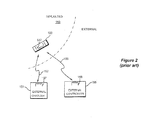
- the microstimulator 100 is illustrated as implanted in a patient 150, and further shown are various external components that may be used to support the implanted microstimulator 100.
- An external controller 155 may be used to program and test the microstimulator 100 via communication link 156.
- Such link 156 is generally a two-way link, such that the microstimulator 100 can report its status or various other parameters to the external controller 155.
- Communication on link 156 occurs via magnetic inductive coupling.
- a coil 158 in the external controller 155 is excited to produce a magnetic field that comprises the link 156, which magnetic field is detected at the coil 147 in the microstimulator.
- the coil 147 is excited to produce a magnetic field that comprises the link 156, which magnetic field is detected at the coil 158 in the external controller.
- the magnetic field is modulated, for example with Frequency Shift Keying (FSK) modulation or the like, to encode the data.
- FSK Frequency Shift Keying
- An external charger 151 provides power used to recharge the battery 145 ( Fig. 1 ). Such power transfer occurs by energizing the coil 157 in the external charger 151, which produces a magnetic field comprising link 152. This magnetic field 152 energizes the coil 147 through the patient 150's tissue, and which is rectified, filtered, and used to recharge the battery 145 as explained further below.
- Link 152 can be bidirectional to allow the microstimulator 100 to report status information back to the external charger 151. For example, once the circuitry 144 in the microstimulator 100 detects that the power source 145 is fully charged, the coil 147 can signal that fact back to the external charger 151 so that charging can cease. Charging can occur at convenient intervals for the patient 150, such as every night.
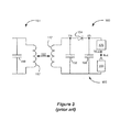
- FIG 3 illustrates salient portions of the microstimulator's power circuitry 160.
- Charging energy i.e., the magnetic charging field
- the coil 147 in combination with capacitor 162 comprises a resonant circuit, or tank circuit, which produces an AC voltage at Va.
- This AC voltage is rectified by rectifier circuitry 164, which can comprise a well-known 4-diode bridge circuit, although it is shown in Figure 3 as a single diode for simplicity.
- Capacitor 166 assists to filter the signal at node Vb, such that Vb is essentially a DC voltage, although perhaps having a negligible ripple.
- charging circuitry 170 Intervening between Vb and the rechargeable battery 145 is charging circuitry 170, which ultimately takes the DC voltage Vb and uses it to produce a controlled battery charging current, Ibat.
- Charging circuitry 170 is well known.
- the power circuitry 160 may include other components not shown for simplicity.
- microstimulator 100 is implanted at a first location, and a second microstimulator 101 is implanted at a second location. Additional microstimulators could also be implanted if more complicated therapies are indicated, but only two microstimulators are shown in Figure 4 for simplicity. Microstimulators 100 and 101 may operate independently or may operate in a coordinated manner.
- the external controller 155 can communicate with each microstimulator independently, with communications accompanied by a header containing an address of the microstimulator. Such addressing ensures no confusion when communicating with the two microstimulators 100 and 101, and thus allows each to be independently programmed and monitored by the external controller 155. Such addressing also allows the two microstimulators 100 and 101 to communicate with each other.
- microstimulators 100 and 101 will eventually need to have their batteries recharged using external charger 151, and such charging presents special challenges. Each of the microstimulators 100 and 101 could be charged independently, but this would take additional time. Even if a patient had only two microstimulators implanted, the total time to charge both would roughly double compared to a single implant, which would comprise a major inconvenience to the patient. Independent charging of the microstimulators also requires some coordination between the microstimulators 100 and 101. For example, the microcontrollers 100 and 101 would have to know when to enable or disable charging by opening or connecting their coils 147.
- implant heating which one skilled in the art will understand is an inevitable side effect of charging using magnetic fields. Heating can result from several different sources, such as eddy currents in conductive portions of the implant, or heating of the various components in the power circuitry 160. Implant heating is a serious safety concern; if an implant exceeds a given safe temperature (e.g., 41 °C), the tissue surrounding the implant may be aggravated or damaged.
- a given safe temperature e.g. 41 °C
- implant heating is a function of both the strength of the magnetic charging field, and the coupling between the external charger 151 and the implant.
- the strength of the magnetic charging field can be increased by increasing the excitation current in the coil 157 of the external charger 151.
- Increasing the magnetic charging field will increase the current/voltage induced in the coil 147 of the microstimulator 100, which increases the battery charging current, Ibat ( Fig. 3 ).
- Ibat battery charging current
- Coupling between the external charger 151 and the implant affects how readily the magnetic charging field is passed to the implant, i.e., how strongly the effect of the magnetic charging field is felt at the implant. Many factors affecting coupling, such as the inductances of the coil 157 in the external charger 151 and the coil 147 in the implant, alignment, angle and distance between the coils 151 and 147, the permittivity of any materials (e.g., tissue, air) between the coils, etc. Coupling between an external charger and an implant is discussed further in U.S. Patent Application Serial No. 12/498,049, filed July 6, 2009 . Generally speaking, if the coupling between the coils is relatively high, a relatively large current/voltage will be induced in implant coil 147, leading to faster charging and higher power dissipation (higher temperatures) in the implant.
- microstimulator 101 is located deeper in the patient, and is therefore farther away from the external charger 151 than is microstimulator 100.
- angle ⁇ between the coil 147 in microstimulator 101 and coil 157 in external charger 151 is relatively large, and the offset of their axes D is relatively large.
- microstimulator 100 when the external charger 151 produces a magnetic charging field, microstimulator 100 will charge more quickly-and will generate more heat-than will microstimulator 101. As noted, this makes optimization difficult. If the generated magnetic charging field is optimized to charge microstimulator 101 as quickly as possible at a safe temperature, then microstimulator 100 would become too hot. By contrast, if the generated magnetic charging field is optimized to charge microstimulator 100 as quickly as possible at a safe temperature, then microstimulator 101 would charge too slowly.
- Figure 1 illustrates a microstimulator implant, including a battery requiring periodical recharging from an external charger, in accordance with the prior art.
- Figure 2 shows the implant in communication with, inter alia, an external charger in accordance with the prior art.
- FIG. 3 illustrates charging circuitry within the implant in accordance with the prior art.
- Figure 4 illustrates duty cycling the power at the external charger to control implant temperature in accordance with the prior art.
- Figures 5A-5C illustrate a simulation in accordance with one example.
- Figure 6 illustrates the relation between battery charging current (Ibat) and the voltage across the battery protection circuitry (Vnab) as revealed from the simulation of Figure 5 .
- Figure 7 illustrates various duty cycles determined for the simulation of Figure 5 which will not exceed a prescribed power limit, and shows the application of such duty cycles on the power at the external charging coil (Iprim(rms)) and in the battery charging current (Ibat).
- Figure 8 illustrates the relation between the average battery charging current (Ibat(avg)) and Vnab as revealed from the simulation of Figure 5 , and shows the Vnab(opt) at which Ibat(avg) is maximized.
- Figure 9 illustrates storage of salient portions of the simulation to prepare the external charger for operation during an actual charging session, in accordance with one embodiment.
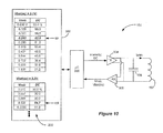
- Figure 10 illustrates circuitry in the external charger in accordance with one embodiment, including a memory storing salient portions of the simulation relevant to optimization of the charger's power parameters.
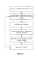
- Figure 11 illustrates a process for adjusting the power level and/or duty cycle of the power at the external charger in accordance with the stored simulation parameters.
- Figure 12 illustrates application of the technique assuming definition of an optimal range for Vnab(opt).
- Figure 13 illustrates a system including an external charger and a plurality of implants for simultaneously charging those implants efficiently and without exceeding a power dissipation limit for the implants.
- Figure 14 illustrates examples of how Vnab can be transmitted from each implant to the external charger in an organized fashion.
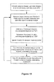
- Figure 15 illustrates a process for adjusting the power level and/or duty cycle at the external charger in accordance with the stored simulation parameters to optimize the charging of a plurality of implants.
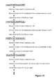
- Figure 16 illustrates an example of the charging of two implants in accordance with the process of Figure 15 .
- An improved external charger for a battery in an implantable medical device and techniques for simultaneously charging batteries in multiple implants using such improved external charger, is disclosed.
- simulation data is used to model the power dissipation of the charging circuitry in an implant at varying levels of implant power.
- a power dissipation limit is chosen to constrain the charging circuitry from producing an inordinate amount of heat to the tissue surrounding the implant, and duty cycles are determined for the various levels of input intensities to ensure that the power limit is not exceeded.
- a maximum simulated average battery current determines the optimal (i.e., quickest) battery charging current, and at least an optimal value for a parameter indicative of that current, for example, the voltage across the battery charging circuitry, is determined and stored in the external charger.
- the actual value for that parameter is reported from multiple implants to the external charger.
- the external charger infers from the magnitudes of the parameters which of the implants has the highest and lowest coupling to the external charger, and so designates those implants as "hot” and "cold.”
- the intensity of the magnetic charging field is optimized for the cold implant consistent with the simulation to ensure that the cold implant is charged with a maximum (fastest) battery charging current.
- the duty cycle of the magnetic charging field is also optimized for the hot implant consistent with the simulation to ensure that the hot implant does not exceed the power dissipation limit. As a result, charging is optimized to be fast for all of the implants, while still safe from a tissue heating perspective.
- microstimulator power circuitry 160 of Figure 3 Reference is made to the microstimulator power circuitry 160 of Figure 3 . While this circuitry is exemplary, it should be understood that the disclosed technique is not limited to use with the particular power circuitry 160 shown.
- the power circuitry 160 within the implant will draw power during the reception of a magnetic charging field from the external charger 151.
- the coil 147, its associated tank capacitor 162, the rectification circuitry (diode) 164, charging circuitry 170, and the battery 145 itself will all dissipate power in the form of heat.
- Capacitor 166 will draw a comparatively negligible amount of power, and thus is not further discussed). The sum total of the powers dissipated by each of these components must be considered when understanding how the tissue surrounding the implant 100 will heat up during a charging session.
- animal studies show that for a particular multiple-electrode microstimulator device, a radiated power of 32 mW will raise the temperature of the tissue surrounding the implant by approximately 4 °C, while a total radiated power of 25.6 mW will raise the temperature by 3.2 °C.
- these values are only exemplary, and could vary; future values could be determined that are more accurate, safer, etc.
- such animal studies have correlated power dissipation to tissue heating for a given implant.
- Simulations show that power dissipation from the various components in the power circuitry 160 is complex and non-linear in nature.
- One such simulation 200 is illustrated in Figures 5A , 5B , and 5C .
- certain portions from simulation 200 are preferably stored in the external charger 151 and will be used to regulate charging.
- simulation 200 is explained.
- open circuit battery voltages e.g., 3.3V, 3.7V, 4.1V, etc.
- Vbat(oc) 3.1 V
- 3.3V 3.3V
- 3.7V 3.7V
- 4.1V 4.1V
- a simulation program useful in generating a simulation 200 is Mentor Graphics Design Architect.
- the simulation 200 assumes a particular coupling factor between the primary coil 157 in the external charger 151 and the secondary coil 147 in the implant 100, which coupling factor is modeled taking into account factors affecting such coupling, such as coil inductances, coil alignment, the distance and permittivity of any materials (e.g., tissue, air) between the coils, etc.
- the coupling factor ultimately results in a simulated induced current in charging coil 147 in the implant (Isec(rms)), a current in the associated tank capacitor 162 (Icap(rms)), a voltage across the coil 147 (Vcoil(rms)), a DC voltage produced by the rectifier circuit (diode) 164 (Vna), a battery charging current (Ibat), and a battery voltage (Vbat) resulting from the input of the battery charging current, which battery voltage takes into account the internal resistance of the battery 145 and which is therefore different from the open-circuit battery voltage, Vbat(oc).
- relevant parameters for the various components in the power circuitry 160 are input into the simulation program to allow it to generate the simulation results.
- Vnab represents the difference between Vna and Vbat. Because the charging circuitry 170 is in line with the battery charging current, Ibat, any excessive voltage build up across the charging circuitry comprises undesired heat generation. Unfortunately, modeling shows that the amount of heat dissipation from the charging circuitry 170 increases essentially exponentially as the battery charging current increases. This is shown in Figure 6 : as the battery charging current Ibat increases, the voltage built up across the battery protection circuitry Vnab increases at an increasingly fast rate. Because the power dissipated by the charging circuit 170 equals the current times the voltage, the power too essentially exponentially increases. In short, the parameter Vnab correlates with excessive charging power wasted as heat, and as will be seen below, is monitored and controlled in the disclosed technique to permit charging at an optimally efficient level.
- the simulation 200 can further calculate the power dissipated by the various components in the power circuitry 160, as shown in Figure 5B , which powers essentially comprise the product of the voltage across and current through the various components.
- the power drawn by each component is represented by the element numeral for the component: for example, the power drawn by the battery 145 during charging is denoted as P 145.
- Pfes represents power drawn by front end switches in series with the charging circuitry 170, which switches are not depicted for simplicity because their power dissipations are relatively small.
- the sum of the power dissipated by each of the components in the power circuitry 160 is shown in the last column in Figure 5B (Ptotal).
- a review of the Ptotal parameter in simulation 200 illustrates a tissue heating concern for the designer.
- an acceptable level of total power dissipated by the power circuitry 160 should not exceed the 32 mW power dissipation limit in one example-a temperature known by experimentation to increase surrounding tissue by 4 °C.
- all but the top three rows in Figure 5B exceed this value (bolded for easy viewing).
- simulation 200 shows that at higher external charger intensities (i.e., higher Iprim(rms)), the total heat generated in the implant 100 may be excessive.
- duty cycle the power at the external charger 151, which computed duty cycle is shown in Figure 5C .
- the duty cycle ensures that the power dissipation limit is not exceeded by dividing the limit (e.g., 32 mW) by the simulated total power draw assuming no duty cycling (Ptotal).
- the telemetry window may be 10 sec for example, meaning that the period for duty cycling is typically about 10 times larger, or 100 sec. While the telemetry window TW can be fixed, it can also be made to vary depending on how long is needed to send data back to the external charger 151. For example, the TW can be set to the exact time needed for data transmission, with the on portion of the cycle similarly scaled to match the duty cycle required. A shorter duration for the total period of the duty cycle reduces ripple in the temperature of the implant 100.
- this duty cycle is imposed on the primary coil in the external charger (Iprim(rms)), which causes the same duty cycle in the battery charging current, Ibat.
- An average battery current, Ibat(avg) can be calculated from the product of Ibat and the duty cycle to give an over-time indication of the amount of charging current that is being received by the battery, despite the duty cycling. The significance of Ibat(avg) will be discussed further below.
- the simulated total power dissipated was 38.6 mW, above the 32 mW limit. Therefore, duty cycling is imposed as a heat control measure, in addition to the desire for an off period to allow for back telemetry. Such duty cycling equals 82.9 % (32/38.6) to ensure a total dissipated power of not more than 32 mW.
- the fifth row is similarly processed to determine a duty cycle of 61.2%, and its effects on Iprim(rms) and Ibat are shown.
- the computed duty cycles for the less-heat-intensive 25.6 mW/3.2 °C limit which limit may be chosen to even further minimize patient discomfort or injury due to heat generation in the power circuitry 160.
- the duty cycles are computed by dividing the limit (25.6 mW) by the simulated total powers (Ptotal).
- Ibat(avg) the average battery current
- Ibat(avg)(opt) is at the same time optimized to allow no more than 32 mW power dissipation on average. Ibat(avg)(opt) is thus optimized for both speed and heat dissipation.
- Vnab the voltage that builds across the charging circuitry 170
- Vna the voltage that builds across the charging circuitry 170
- the Vnab parameter is easily measured in the implant, and as noted earlier represents wasted heat.
- Figure 8 shows a graph of Ibat(avg) v. Vnab for the simulation 200 for the 32 mW/4 °C limit, and shows the maximum at 11.6 mA.
- the corresponding Vnab for this value, Vnab(opt) is 0.243 V (see fourth row, Fig. 5A ).
- Vnab(opt) thus represents the voltage across the charging circuitry 170 that provides the quickest charging of the implant battery 145, but which is safe from a heating perspective. As will be seen below, it is preferable to maintain Vnab at Vnab(opt) during charging.
- a power dissipation limit is chosen, such as the 32 mW/ 4 °C limit discussed previously.
- the external charger 151/implant 100 system is simulated to determine the relationship between Vnab and the duty cycle needed to stay compliant with the power dissipation limit. This simulation can occur assuming a particular open-circuit battery voltage (Vbat(oc)) for the battery 145 in the implant 100.
- Vnab and Ibat(avg) are determined using the duty cycle, and an optimal Vnab(opt) is determined which corresponds to the maximum Ibat(avg).
- Vnab v. DC, and Vnab(opt) are stored in memory of the external charger (or the implant so that it could be made accessible to the external charger), as will be discussed further shortly.
- the preparation process repeats for a new battery voltage Vbat(oc) if necessary, but as noted earlier this may not be required if the various simulated parameters do not vary strongly with Vbat(oc).
- Figure 10 shows the external charger 151 as prepared with the parameters stored from Figure 9 .
- memory 302 could contain the same information for other power dissipation limits (e.g., 25.6 mW/3.2 °C) as well, but this is not shown for simplicity.
- the memory 302 containing these parameters is coupled to (or could comprise part of) the microcontroller 300 in the external charger 151.
- the transmitter 304 and receiver 306 circuits coupled to the external charger's coil 157, which circuitry is well known.
- the transmitter 304 produces an AC signal to cause the L-C tank circuit (156/157) to resonate and in turn generate the magnetic charging field.
- the transmitter 304 receives control signals from the microcontroller 300 to indicate the intensity (e.g., the magnitude of Iprim) and the duty cycle of the transmitter 304.
- the receiver 306 receives data transmitted periodically from the implant 100, e.g., during the telemetry window (TW) or off portions of the duty cycle (see Fig. 7 ). Such data may be transmitted using radio-frequency (RF) telemetry, or Load Shift Keying (LSK) for example. (LSK is further discussed in U.S. Patent Application Serial No. 12/354,406, filed January 15, 2009 , for example).
- RF radio-frequency
- LSK Load Shift Keying
- Vbat(oc) capacity of the battery 145 during charging
- Vbat(oc) capacity of the battery 145 during charging
- Battery capacity is similarly reported in the disclosed system, but additionally, the Vnab value measured at the implant 100 is also transmitted. Reporting of Vnab to the external charger 151 can take place at any suitable interval during charging, such as once every 100 seconds or so. The more frequently Vnab is reported, the more frequently charging can be optimized during the charging session.
- the external charger 151 is turned on (e.g., by the patient), and generates a magnetic charging field using an initial intensity level (i.e., an initial Iprim) and an initial duty cycle.
- Simulation 200 does not help much in determining initial values for the power and duty cycle levels used at the external charger, as the coupling to the implant 100 during a real charging session cannot be perfectly known in advance. For example, different patients may have their implants located at different depths in their tissues, or may have different physical alignments between their external chargers and their implants.
- the initial power and duty cycle values are not important as they will be changed in accordance with the disclosed technique as charging progresses, although they are logically set to initial values guaranteed not to injure the patient.
- an alignment period is instigated when charging is initiated with the intent of quickly adjust the primary current to reach the target value. During this alignment period, relatively short duration on times of the charging field are used (enough to provide an adequate read of Vbat(oc), Vnab, etc.) to adjust the primary current. Once the target primary current is reached, the external charger will apply the target duty cycle identified as optimal.
- the battery voltage (Vbat(oc)) and the voltage across the charging circuitry (Vnab) are measured at the implant 100, and telemetered to the external charger.
- telemetry can comprise RF or LSK telemetry performed during the telemetry window (TW) or off periods in the duty cycle.
- TW telemetry window
- How often to communicate, just like the time used for communication during the telemetry window (TW), may also be determined by the length of the needed communication between implant and charger. Increasing the frequency of communication will reduce temperature ripple in the implant 100.
- the duty cycle of the magnetic charging field would also be changed to match the Vnab being reported. Modifying the duty cycle to match Vnab is important to ensure proper compliance with the power dissipation limit. For example, and referring again to Figure 10 , assume again that Vnab is near 0.293V, but that the duty cycle currently imposed at the transmitter 304 is 85%. Reference to the stored parameters in memory 302 shows that this duty cycle is too high, and will produce too much heat, i.e., more than the 32 mW power dissipation limit. To keep the total dissipated power compliant with the limit, the microcontroller 300, upon consulting memory 302, will change the duty cycle to 61.2%.
- Vnab(opt) can also represent a range of acceptable Vnab values.
- the simulation 200 in Figure 5C shows three values for Ibat(avg) over 11 mA (rows four through six), which correspond to Vnab values ( Fig. 5A ) of 0.243 to 0.319V.
- Vnab(opt) can be set to a range between 0.243 to 0.319V, as illustrated in Figure 12 .
- Vnab is reported within this range, the intensity at the external charger (Iprim) would not be changed. However, even if the intensity is not changed, it may still be prudent to vary the duty cycle in accordance with Vnab to ensure compliance with the heat limit.
- Ibat(avg) does not change appreciably across the specified Vnab range (from 11.6 to 11.0 mA)
- the duty cycle changes rather sharply (from 82.9 to 53.6%).
- changing duty cycling within the Vnab(opt) range might not be necessary. In any event, defining Vnab(opt) as a range will simplify operation of the technique, and will require less frequent modification of the magnetic charging field at the external charger 151.
- the implants will charge at different rates depending on their coupling with respect to the external charger. Those implants with a high coupling factor may charge too fast (too hot), while those with a low coupling will charge too slowly. In short, it has been difficult to optimize the charging procedure to ensure quick charging without the risk of overheating.
- each of the 'x' implants reports their measured Vnab and Vbat(oc) values back to the external charger 151 during charging.
- any given implant's transmission of these parameters would likely be accompanied by an address, which address would differ for each implant.
- Such address allows the external charger 151 to know which Vnab and Vbat(oc) came from which of the 'x' implants 100, i.e., Vnab1 and Vbat1(oc) from implant1, etc.
- each of the implants can be allotted a portion of the off period. Or, as shown at the bottom, the implants can take turns occupying the entirety of successive off periods. As before, depending on the length of the transmission(s) during the off period, the length of the on portion can be scaled accordingly to keep the duty cycle of the magnetic charging field at a prescribed value. Controlling the various implants to transmit in either of these fashions can be facilitated by communications between the implants.
- implant1 can signal to implant2 when it is finished transmitting its data (Vnab1, Vbat1(oc)), so that implant2 can begin its transfer, etc.
- Vnab1, Vbat1(oc) data
- implant2 can begin its transfer, etc.
- inter-implant communications are facilitated when the magnetic charging field is not present during the off periods.
- the implants may be programmed to transmit only during pre-defined non-overlapping time slots. It is not important to application of the invention how the relevant parameters are transmitted to the external charger 151.
- the external charger 151 When the parameters are received for each implant, the external charger 151 performs the steps shown in Figure 15 to safely optimize charging for the implants. Like the similar single-implant method of Figure 11 , these steps can be embodied in a program executable within the charger's microcontroller 300.
- the external charger 151 is turned on (e.g., by the patient), and generates a magnetic charging field using an initial intensity level (i.e., an initial Iprim) and an initial duty cycle.
- an initial intensity level i.e., an initial Iprim
- an initial duty cycle i.e., an initial duty cycle
- the battery voltage (Vbat(oc)) and the voltage across the charging circuitry 170 (Vnab) are measured at each of the 'x' implants 100, and are telemetered to the external charger 151 as was discussed with reference to Figure 14 . Because multiple implants will be transmitting their values, it may be desirable to increase the frequency of transmissions so that the total time to report the implants' parameters is not too long.
- Vnab values for each are compared to determine a maximum Vnab and a minimum Vnab, with the goal of designating a "hot" implant and a "cold” implant.
- Higher values of Vnab correspond to higher levels of wasted heat, which indicates higher coupling with the external charger 151.
- Vnab values reported from microstimulator 100 would be higher than for microstimulator 101 because of microstimulator 100's higher coupling to the external charger 151.
- the intensity and duty cycle of the magnetic charging field are optimized at the external charger to ensure that no implant overheats, while still attempting to charge all implants efficiently.
- the cold implant(j) at any given time is used to set the intensity
- the hot implant(i) at any given time is used to set the duty cycle.
- the intensity (Iprim) of the magnetic charging field is varied to approach a value for the average battery current Ibat(avg)(opt) that will charge the battery in implant(j) the quickest.
- that optimal current corresponds to Vnab(opt) (see, e.g., Fig. 8 ), and so the intensity is changed to try and move Vnab(j) toward Vnab(opt), with the intensity increased if Vnab(j) ⁇ Vnab(opt) and decreased if Vnab(j)>Vnab(opt).
- Vnab(opt) may vary depending on the reported battery voltage, Vbat(oc)(j), and so this parameter can be considered at this point in the process if necessary.
- the next step would be to choose a duty cycle for the external charger 151 that would maximize charging of the cold implant (implant (j)) by choosing a duty cycle that would allow implant(j) to heat up to the power dissipation limit (e.g., 32 mW/4 °C).
- the power dissipation limit e.g. 32 mW/4 °C.
- the duty cycle is chosen to ensure that the "hot" implant (implant(i)) does not exceed the power dissipation limit.
- the duty cycle for "hot” implant(i) can be chosen with consideration to the hot implant(i)'s battery voltage, Vbat(oc)(i), if necessary). The result is that the "hot” implant will be allowed to approach but not exceed the power dissipation limitation, while the "cold” implant is charged with an optimally fast current, although with a duty cycle that would otherwise be less than optimal.
- full implants recognize when their batteries are at capacity; decouple themselves from receiving further power; and indicate such full capacity to the external charger 151 so that they can be discluded from the analysis and optimization routine of Figure 15 .
- This can occur in one example by having full implants actively detune themselves from the frequency of the magnetic charging field.
- Such active detuning can occur by either disconnecting or shorting the coil 147 or its tuning capacitor 162 (see Fig. 5A ), which changes the resonant frequency of the L-C (tank) circuit formed by those two components.
- the L-C tank circuit With the full implant so detuned, the L-C tank circuit will no longer resonate in response to the magnetic charging field, such that Vcoil (and consequently Vna and Vnab) are essentially zero, or are below some preset minimal limit. In effect, no power is being coupled to the full implant, its battery will not be further charged, and it is not at risk of overheating. Accordingly, when this negligible Vnab value is reported for a full implant, the external charger 151 can know to disclude it from the hot/cold analysis, and any further optimization of the intensity or duty cycle of the magnetic charging field.
- FIG. 16 An example illustrating the operation of the charging process of Figure 15 is illustrated in Figure 16 , which for simplicity assumes a two-implant system, implant(1) and implant(2). For further simplicity, it is assumed that the open-circuit battery voltage in each of implants(1) and (2) equals 3.1V, to allow the reader easy reference to the values tabulated and stored in the external charger 151 in Figure 13 .
- implants(1) and (2) report Vnab1 and 2 values of 0.109 and 0.401 respectively to the external charger 151, as shown at the top of Figure 16 .
- the smaller value for Vnab1 indicates lower coupling between implant1 and the external charger 151, perhaps because implant1 is farther away.
- Implant1 is therefore deemed the "cold" implant, and the intensity of the magnetic charging field (Iprim) is adjusted to try and optimize the battery charging current in implant1.
- Iprim is increased.
- Vnab1 and 2 values of 0.293 and 0.722 are reported as shown in Figure 16 . It is not surprising that these values are both larger, because it was previously decided in the last iteration to increase Iprim, and hence increase the intensity of the magnetic charge field.
- a comparison of Vnab1 and Vnab2 shows that implant1 is cold.
- Vnab(opt); a DC corresponding to a particular Vnab can be interpolated or extrapolated from the simulation 200, and are therefore not necessarily constrained to actual values appearing in the simulation.
- interpolation was not shown to keep discussion of the technique simple.
- Vnab(opt) Vnab(opt)
- the disclosed technique limits the total power dissipated by the implant.
- the technique can be constrained to control heating at only a portion of the implant.
- the technique can be employed to limit the local heating at any section of the implant.
- the technique can use a parameter (perhaps different from Vnab) indicative of heating to that section, and limiting heating of that particular section to tolerable limits.
- this modification to the technique would only consider power dissipated as heat in the relevant section of the device.
- Vnab is used in this disclosure as the measure indicative of excess power dissipation.
- other parameters from the implant indicative of incoming power or power dissipated in heat and which can be used to control that power can also be used, such as total power delivered to the battery, ripple of the coil voltage, ripple of the rectified voltage, on time of the rectifying circuit, duty cycle of the rectifying circuit, etc.
- these parameters could be measured or inferred in the implant in different ways.
- periodic should not be understood as necessarily taking such actions at set intervals. Instead, “periodic” should be understood as taking a plurality of such actions over time, even if not at set intervals.
Landscapes
- Health & Medical Sciences (AREA)
- Engineering & Computer Science (AREA)
- Biomedical Technology (AREA)
- Nuclear Medicine, Radiotherapy & Molecular Imaging (AREA)
- Radiology & Medical Imaging (AREA)
- Life Sciences & Earth Sciences (AREA)
- Animal Behavior & Ethology (AREA)
- General Health & Medical Sciences (AREA)
- Public Health (AREA)
- Veterinary Medicine (AREA)
- Charge And Discharge Circuits For Batteries Or The Like (AREA)
- Electrotherapy Devices (AREA)
Abstract
Description
- The present invention relates generally to an external charger used to inductively charge a rechargeable battery within a plurality of implantable medical devices such as neurostimulators.
- Implantable stimulation devices generate and deliver electrical stimuli to nerves and tissues for the therapy of various biological disorders, such as pacemakers to treat cardiac arrhythmia, defibrillators to treat cardiac fibrillation, cochlear stimulators to treat deafness, retinal stimulators to treat blindness, muscle stimulators to produce coordinated limb movement, spinal cord stimulators to treat chronic pain, cortical and deep brain stimulators to treat motor and psychological disorders, occipital nerve stimulators to treat migraine headaches, and other neural stimulators to treat urinary incontinence, sleep apnea, shoulder sublaxatian, etc. The present invention may find applicability in all such applications and in other implantable medical device systems, although the description that follows will generally focus on the use of the invention in a Bion™ microstimulator device system of the type disclosed in
U.S. Patent Application Serial No. 12/425,505, filed April 17, 2009 - Microstimulator devices typically comprise a small generally-cylindrical housing which carries electrodes for producing a desired stimulation current. Devices of this type are implanted proximate to the target tissue to allow the stimulation current to stimulate the target tissue to provide therapy for a wide variety of conditions and disorders. A microstimulator usually includes or carries stimulating electrodes intended to contact the patient's tissue, but may also have electrodes coupled to the body of the device via a lead or leads. A microstimulator may have two or more electrodes. Microstimulators benefit from simplicity. Because of their small size, the microstimulator can be directly implanted at a site requiring patient therapy.
-
Figure 1 illustrates an exemplaryimplantable microstimulator 100. As shown, themicrostimulator 100 includes apower source 145 such as a battery, aprogrammable memory 146, electrical circuitry 144, and acoil 147. These components are housed within acapsule 202, which is usually a thin, elongated cylinder, but may also be any other shape as determined by the structure of the desired target tissue, the method of implantation, the size and location of thepower source 145 and/or the number and arrangement of external electrodes 142. In some embodiments, the volume of thecapsule 202 is substantially equal to or less than three cubic centimeters. - The
battery 145 supplies power to the various components within themicrostimulator 100, such the electrical circuitry 144 and thecoil 147. Thebattery 145 also provides power for therapeutic stimulation current sourced or sunk from the electrodes 142. Thepower source 145 may be a primary battery, a rechargeable battery, a capacitor, or any other suitable power source. Systems and methods for charging arechargeable battery 145 will be described further below. - The
coil 147 is configured to receive and/or emit a magnetic field that is used to communicate with, or receive power from, one or more external devices that support the implantedmicrostimulator 100, examples of which will be described below. Such communication and/or power transfer may be transcutaneous as is well known. - The
programmable memory 146 is used at least in part for storing one or more sets of data, including electrical stimulation parameters that are safe and efficacious for a particular medical condition and/or for a particular patient. Electrical stimulation parameters control various parameters of the stimulation current applied to a target tissue including, but not limited to, the frequency, pulse width, amplitude, burst pattern (e.g., burst on time and burst off time), duty cycle or burst repeat interval, ramp on time and ramp off time of the stimulation current, etc. - The illustrated
microstimulator 100 includes electrodes 142-1 and 142-2 on the exterior of thecapsule 202. The electrodes 142 may be disposed at either end of thecapsule 202 as illustrated, or placed along the length of the capsule. There may also be more than two electrodes arranged in an array along the length of the capsule. One of the electrodes 142 may be designated as a stimulating electrode, with the other acting as an indifferent electrode (reference node) used to complete a stimulation circuit, producing monopolar stimulation. Or, one electrode may act as a cathode while the other acts as an anode, producing bipolar stimulation. Electrodes 142 may alternatively be located at the ends of short, flexible leads. The use of such leads permits, among other things, electrical stimulation to be directed to targeted tissue(s) a short distance from the surgical fixation of the bulk of thedevice 100. - The electrical circuitry 144 produces the electrical stimulation pulses that are delivered to the target nerve via the electrodes 142. The electrical circuitry 144 may include one or more microprocessors or microcontrollers configured to decode stimulation parameters from
memory 146 and generate the corresponding stimulation pulses. The electrical circuitry 144 will generally also include other circuitry such as the current source circuitry, the transmission and receiver circuitry coupled tocoil 147, electrode output capacitors, etc. - The external surfaces of the
microstimulator 100 are preferably composed of biocompatible materials. For example, thecapsule 202 may be made of glass, ceramic, metal, or any other material that provides a hermetic package that excludes water but permits passage of the magnetic fields used to transmit data and/or power. The electrodes 142 may be made of a noble or refractory metal or compound, such as platinum, iridium, tantalum, titanium, titanium nitride, niobium or alloys of any of these, to avoid corrosion or electrolysis which could damage the surrounding tissues and the device. - The
microstimulator 100 may also include one ormore infusion outlets 201, which facilitate the infusion of one or more drugs into the target tissue. Alternatively, catheters may be coupled to theinfusion outlets 201 to deliver the drug therapy to target tissue some distance from the body of themicrostimulator 100. If themicrostimulator 100 is configured to provide a drug stimulation usinginfusion outlets 201, themicrostimulator 100 may also include apump 149 that is configured to store and dispense the one or more drugs. - Turning to
Figure 2 , themicrostimulator 100 is illustrated as implanted in apatient 150, and further shown are various external components that may be used to support the implantedmicrostimulator 100. Anexternal controller 155 may be used to program and test themicrostimulator 100 viacommunication link 156.Such link 156 is generally a two-way link, such that themicrostimulator 100 can report its status or various other parameters to theexternal controller 155. Communication onlink 156 occurs via magnetic inductive coupling. Thus, when data is to be sent from theexternal controller 155 to themicrostimulator 100, acoil 158 in theexternal controller 155 is excited to produce a magnetic field that comprises thelink 156, which magnetic field is detected at thecoil 147 in the microstimulator. Likewise, when data is to be sent from themicrostimulator 100 to theexternal controller 155, thecoil 147 is excited to produce a magnetic field that comprises thelink 156, which magnetic field is detected at thecoil 158 in the external controller. Typically, the magnetic field is modulated, for example with Frequency Shift Keying (FSK) modulation or the like, to encode the data. - An
external charger 151 provides power used to recharge the battery 145 (Fig. 1 ). Such power transfer occurs by energizing thecoil 157 in theexternal charger 151, which produces a magneticfield comprising link 152. Thismagnetic field 152 energizes thecoil 147 through thepatient 150's tissue, and which is rectified, filtered, and used to recharge thebattery 145 as explained further below.Link 152, likelink 156, can be bidirectional to allow themicrostimulator 100 to report status information back to theexternal charger 151. For example, once the circuitry 144 in themicrostimulator 100 detects that thepower source 145 is fully charged, thecoil 147 can signal that fact back to theexternal charger 151 so that charging can cease. Charging can occur at convenient intervals for thepatient 150, such as every night. -
Figure 3 illustrates salient portions of the microstimulator'spower circuitry 160. Charging energy (i.e., the magnetic charging field) is received atcoil 147 vialink 152. Thecoil 147 in combination withcapacitor 162 comprises a resonant circuit, or tank circuit, which produces an AC voltage at Va. This AC voltage is rectified byrectifier circuitry 164, which can comprise a well-known 4-diode bridge circuit, although it is shown inFigure 3 as a single diode for simplicity.Capacitor 166 assists to filter the signal at node Vb, such that Vb is essentially a DC voltage, although perhaps having a negligible ripple. Intervening between Vb and therechargeable battery 145 ischarging circuitry 170, which ultimately takes the DC voltage Vb and uses it to produce a controlled battery charging current, Ibat.Charging circuitry 170 is well known. One skilled in the art will recognize that thepower circuitry 160 may include other components not shown for simplicity. - Depending on the patient's condition, it may be desirable to implant more than one microstimulator to provide more complex stimulation to the patient and/or to provide stimulation in different locations. For instance, as shown in the example of
Figure 4 , afirst microstimulator 100 is implanted at a first location, and asecond microstimulator 101 is implanted at a second location. Additional microstimulators could also be implanted if more complicated therapies are indicated, but only two microstimulators are shown inFigure 4 for simplicity.Microstimulators - The
external controller 155 can communicate with each microstimulator independently, with communications accompanied by a header containing an address of the microstimulator. Such addressing ensures no confusion when communicating with the two microstimulators 100 and 101, and thus allows each to be independently programmed and monitored by theexternal controller 155. Such addressing also allows the two microstimulators 100 and 101 to communicate with each other. - Both
microstimulators external charger 151, and such charging presents special challenges. Each of themicrostimulators microstimulators microcontrollers coils 147. - Because of such issues, the inventors consider it preferable to charge both
microstimulators power circuitry 160. Implant heating is a serious safety concern; if an implant exceeds a given safe temperature (e.g., 41 °C), the tissue surrounding the implant may be aggravated or damaged. - Generally speaking, implant heating is a function of both the strength of the magnetic charging field, and the coupling between the
external charger 151 and the implant. The strength of the magnetic charging field can be increased by increasing the excitation current in thecoil 157 of theexternal charger 151. Increasing the magnetic charging field will increase the current/voltage induced in thecoil 147 of themicrostimulator 100, which increases the battery charging current, Ibat (Fig. 3 ). Increasing the battery charging current speeds up charging, but also increases heat dissipation in the device. - Coupling between the
external charger 151 and the implant affects how readily the magnetic charging field is passed to the implant, i.e., how strongly the effect of the magnetic charging field is felt at the implant. Many factors affecting coupling, such as the inductances of thecoil 157 in theexternal charger 151 and thecoil 147 in the implant, alignment, angle and distance between thecoils U.S. Patent Application Serial No. 12/498,049, filed July 6, 2009 implant coil 147, leading to faster charging and higher power dissipation (higher temperatures) in the implant. - Because of differences in the placement of multiple microstimulators in a patient, one could expect that the coupling between the
external charger 151 and those microstimulators would differ. This means that the same magnetic charging field produced by theexternal charger 151 would result in different amounts of power in each of the microstimulators. ConsiderFigure 4 : microstimulator 101 is located deeper in the patient, and is therefore farther away from theexternal charger 151 than ismicrostimulator 100. Moreover, the angle θ between thecoil 147 inmicrostimulator 101 andcoil 157 inexternal charger 151 is relatively large, and the offset of their axes D is relatively large. These factors all contribute to low coupling between theexternal charger 157 andmicrostimulator 101 as compared tomicrostimulator 100. - As a result, when the
external charger 151 produces a magnetic charging field,microstimulator 100 will charge more quickly-and will generate more heat-than will microstimulator 101. As noted, this makes optimization difficult. If the generated magnetic charging field is optimized to charge microstimulator 101 as quickly as possible at a safe temperature, then microstimulator 100 would become too hot. By contrast, if the generated magnetic charging field is optimized to charge microstimulator 100 as quickly as possible at a safe temperature, then microstimulator 101 would charge too slowly. - Finding optimal charging conditions (intensity, duty cycle) when simultaneously charging multiple implants is the subject of this disclosure, and solutions to this problems are disclosed herein.
- The following aspects are preferred embodiments of the invention.
- 1. A method for charging batteries in a plurality of implantable medical devices, comprising:
- (a) generating a charging field during a charging session using an external charger to simultaneously charge the batteries in the implantable medical devices;
- (b) monitoring at the external charger parameters indicative of the coupling between the external charger and each of the implantable medical devices during the charging session; and
- (c) adjusting during the charging session the charging field in accordance with the parameters.
- 2. The method of aspect 1, wherein the charging field is adjusted to optimize the speed with which the batteries in each of the implantable medical devices are charged.
- 3. The method of aspect 2, wherein the charging field is adjusted to maximize a charging speed in one implant while not overheating any other of the implantable medical devices.
- 4. The method of aspect 3, wherein the charging speed is maximized in the one implant by maximizing a battery charging current induced by the charging field in that one implant.
- 5. The method of aspect 2, wherein the one implant whose battery charging current is maximized has a lowest coupling with the external charger.
- 6. The method of aspect 1, wherein the parameters are further indicative of the battery charging current in each of the implantable medical devices.
- 7. The method of aspect 1, wherein adjusting the charging field comprises adjusting its intensity or duty cycle, or its intensity and duty cycle.
- 8. The method of aspect 1, wherein monitoring the parameters at the external charger comprises receiving the parameters by telemetry from the implantable medical devices.
- 9. The method of aspect 1, further comprising: (d) repeating steps (b) through (c) periodically during the charging session.
- 10. A method for charging batteries in a plurality of implantable medical devices, comprising:
- (a) generating a magnetic charging field during a charging session using an external charger;
- (b) measuring during the charging session at least one parameter in each of the implantable medical devices;
- (c) telemetering during the charging session the at least one parameter for each of the implantable medical devices to the external charger; and
- (d) adjusting during the charging session the magnetic charging field in accordance with at least some of the telemetered parameters to maximize a charging speed in one implant while not exceeding a maximum power dissipation limit for any other of the implantable medical devices.
- 11. The method of
aspect 10, wherein the charging speed is maximized by maximizing a battery charging current induced by the magnetic charging field. - 12. The method of aspect 11, wherein the at least one parameters are indicative of the battery charging current in each of the implantable medical devices.
- 13. The method of aspect 11, wherein the at least one parameter comprises a voltage across circuitry in line with the battery charging current.
- 14. The method of aspect 13, wherein the one implant whose battery charging current is maximized has a lowest coupling with the external charger.
- 15. The method of
aspect 10, wherein adjusting the magnetic charging field comprises adjusting its intensity or duty cycle, or its intensity and duty cycle. - 16. The method of
aspect 10, wherein the magnetic charging field is duty cycled, and wherein the at least one parameter for each of the implantable medical devices are telemetered during off periods in the duty cycle. - 17. The method of
aspect 10, further comprising: (e) repeating steps (b) through (d) periodically during the charging session. - 18. The method of
aspect 10, further comprising between steps (c) and (d):- determining a first implant of the plurality of implants having a highest
coupling to the external charger, and a second implant of the plurality of implants having lowest coupling to the external charger.
- determining a first implant of the plurality of implants having a highest
- 19. The method of aspect 18, wherein the first and second implants are determined using at least one of the parameters telemetered from each of the implants.
- 20. The method of aspect 18, wherein adjusting the magnetic charging field comprises (i) adjusting an intensity of the magnetic charging field in accordance with at least one parameter telemetered from the second implant, and (ii) adjusting a duty cycle of the magnetic charging field in accordance with at least one parameter telemetered from the first implant.
- 21. The method of aspect 18, wherein adjusting the magnetic charging field comprises adjusting an intensity and duty cycle of the magnetic charging field to maximize the speed of charging of the second implant while ensuring the first implant does not exceed a maximum power dissipation limit.
- 22. The method of aspect 18, wherein determining the first implant comprises determining an implant with the smallest of the at least one parameters, and wherein determining the second implant comprises determining a largest of the at least one parameters.
- 23. The method of aspect 18, wherein determining the first and second implants comprises discluding any of the plurality of implants having a battery that is fully charged.
- 24. The method of
aspect 10, further comprising between steps (c) and (d):- comparing at least some of the telemetered parameters to data stored in the external charger.
- 25. The method of aspect 24, wherein the magnetic charging field is adjusted based on the comparison.
- 26. The method of
aspect 10, wherein the one implant whose charging speed is maximized has a lowest coupling with the external charger. -
Figure 1 illustrates a microstimulator implant, including a battery requiring periodical recharging from an external charger, in accordance with the prior art. -
Figure 2 shows the implant in communication with, inter alia, an external charger in accordance with the prior art. -
Figure 3 illustrates charging circuitry within the implant in accordance with the prior art. -
Figure 4 illustrates duty cycling the power at the external charger to control implant temperature in accordance with the prior art. -
Figures 5A-5C illustrate a simulation in accordance with one example. -
Figure 6 illustrates the relation between battery charging current (Ibat) and the voltage across the battery protection circuitry (Vnab) as revealed from the simulation ofFigure 5 . -
Figure 7 illustrates various duty cycles determined for the simulation ofFigure 5 which will not exceed a prescribed power limit, and shows the application of such duty cycles on the power at the external charging coil (Iprim(rms)) and in the battery charging current (Ibat). -
Figure 8 illustrates the relation between the average battery charging current (Ibat(avg)) and Vnab as revealed from the simulation ofFigure 5 , and shows the Vnab(opt) at which Ibat(avg) is maximized. -
Figure 9 illustrates storage of salient portions of the simulation to prepare the external charger for operation during an actual charging session, in accordance with one embodiment. -
Figure 10 illustrates circuitry in the external charger in accordance with one embodiment, including a memory storing salient portions of the simulation relevant to optimization of the charger's power parameters. -
Figure 11 illustrates a process for adjusting the power level and/or duty cycle of the power at the external charger in accordance with the stored simulation parameters. -
Figure 12 illustrates application of the technique assuming definition of an optimal range for Vnab(opt). -
Figure 13 illustrates a system including an external charger and a plurality of implants for simultaneously charging those implants efficiently and without exceeding a power dissipation limit for the implants. -
Figure 14 illustrates examples of how Vnab can be transmitted from each implant to the external charger in an organized fashion. -
Figure 15 illustrates a process for adjusting the power level and/or duty cycle at the external charger in accordance with the stored simulation parameters to optimize the charging of a plurality of implants. -
Figure 16 illustrates an example of the charging of two implants in accordance with the process ofFigure 15 . - An improved external charger for a battery in an implantable medical device (implant), and techniques for simultaneously charging batteries in multiple implants using such improved external charger, is disclosed. In one example, simulation data is used to model the power dissipation of the charging circuitry in an implant at varying levels of implant power. A power dissipation limit is chosen to constrain the charging circuitry from producing an inordinate amount of heat to the tissue surrounding the implant, and duty cycles are determined for the various levels of input intensities to ensure that the power limit is not exceeded. A maximum simulated average battery current determines the optimal (i.e., quickest) battery charging current, and at least an optimal value for a parameter indicative of that current, for example, the voltage across the battery charging circuitry, is determined and stored in the external charger.
- During charging, the actual value for that parameter is reported from multiple implants to the external charger. The external charger infers from the magnitudes of the parameters which of the implants has the highest and lowest coupling to the external charger, and so designates those implants as "hot" and "cold." The intensity of the magnetic charging field is optimized for the cold implant consistent with the simulation to ensure that the cold implant is charged with a maximum (fastest) battery charging current. The duty cycle of the magnetic charging field is also optimized for the hot implant consistent with the simulation to ensure that the hot implant does not exceed the power dissipation limit. As a result, charging is optimized to be fast for all of the implants, while still safe from a tissue heating perspective.
- Prior to discussing the optimization of charging batteries in multiple implants, a technique for optimizing the charging of a battery in a single implant is discussed with reference to
Figures 5A-12 , which subject matter is disclosed inU.S. Patent Application Serial No. 12/575,733, filed October 8, 2009 - Reference is made to the
microstimulator power circuitry 160 ofFigure 3 . While this circuitry is exemplary, it should be understood that the disclosed technique is not limited to use with theparticular power circuitry 160 shown. - Various components in the
power circuitry 160 within the implant will draw power during the reception of a magnetic charging field from theexternal charger 151. In particular, thecoil 147, its associatedtank capacitor 162, the rectification circuitry (diode) 164, chargingcircuitry 170, and thebattery 145 itself will all dissipate power in the form of heat. (Capacitor 166 will draw a comparatively negligible amount of power, and thus is not further discussed). The sum total of the powers dissipated by each of these components must be considered when understanding how the tissue surrounding theimplant 100 will heat up during a charging session. For example, animal studies show that for a particular multiple-electrode microstimulator device, a radiated power of 32 mW will raise the temperature of the tissue surrounding the implant by approximately 4 °C, while a total radiated power of 25.6 mW will raise the temperature by 3.2 °C. Of course, these values are only exemplary, and could vary; future values could be determined that are more accurate, safer, etc. In any event, such animal studies have correlated power dissipation to tissue heating for a given implant. - It is desired to keep the total dissipated power at or below a limit to ensure that the patient's tissue will not overheat. Because a 4 °C rise in tissue temperature is generally accepted as safe for a patient, one example of the technique labors to keep the total power dissipated from the
power circuitry 160 at or below 32 mW. Of course, different limits could be chosen, such as the 25.6 mW/3.2 °C limit discussed above. - Simulations show that power dissipation from the various components in the
power circuitry 160 is complex and non-linear in nature. Onesuch simulation 200 is illustrated inFigures 5A ,5B , and5C . As will be discussed further below, certain portions fromsimulation 200 are preferably stored in theexternal charger 151 and will be used to regulate charging. However, before discussing a charging operation,simulation 200 is explained. -
Simulation 200 shows the effect of varying the intensity (e.g., current) in the external controller's charging coil 157 (Iprim(rms)) on the various components in thepower circuitry 160 of theimplant 100, with each successive row representing an increasing value for Iprim(rms). Because thesimulation 200 results will vary depending on how full or depleted theimplant battery 145 is at a given moment, the depicted simulation assumes a battery with a particular open-circuit voltage of Vbat(oc)=3.1 V. Although not depicted,other simulations 200 at other open circuit battery voltages (e.g., 3.3V, 3.7V, 4.1V, etc.) may also be generated to provide accurate simulation results as battery capacity starts to fill during charging. For example, if thebattery 145 has a full capacity of Vbat(oc)=4.1V, thensimulations 200 may be generated for Vbat(oc)=3.1 V, 3.3V, 3.7V, and 4.1V to cover a range of expected battery capacity. However, if the various parameters withinsimulation 200 do not vary appreciably with Vbat(oc), then the generation ofadditional simulations 200 for different battery capacities may not be necessary. A simulation program useful in generating asimulation 200 is Mentor Graphics Design Architect. - The
simulation 200 assumes a particular coupling factor between theprimary coil 157 in theexternal charger 151 and thesecondary coil 147 in theimplant 100, which coupling factor is modeled taking into account factors affecting such coupling, such as coil inductances, coil alignment, the distance and permittivity of any materials (e.g., tissue, air) between the coils, etc. In the depicted simulation, a coupling factor k=0.017 was chosen to conservatively simulate a worst case alignment between the chargingcoils coil 147 in the implant (Isec(rms)), a current in the associated tank capacitor 162 (Icap(rms)), a voltage across the coil 147 (Vcoil(rms)), a DC voltage produced by the rectifier circuit (diode) 164 (Vna), a battery charging current (Ibat), and a battery voltage (Vbat) resulting from the input of the battery charging current, which battery voltage takes into account the internal resistance of thebattery 145 and which is therefore different from the open-circuit battery voltage, Vbat(oc). Of course, relevant parameters for the various components in the power circuitry 160 (resistances, capacitance, inductances, coupling factor, etc.) are input into the simulation program to allow it to generate the simulation results. - Of particular interest in
simulation 200 is the voltage across the chargingcircuitry 170, Vnab, which represents the difference between Vna and Vbat. Because the chargingcircuitry 170 is in line with the battery charging current, Ibat, any excessive voltage build up across the charging circuitry comprises undesired heat generation. Unfortunately, modeling shows that the amount of heat dissipation from the chargingcircuitry 170 increases essentially exponentially as the battery charging current increases. This is shown inFigure 6 : as the battery charging current Ibat increases, the voltage built up across the battery protection circuitry Vnab increases at an increasingly fast rate. Because the power dissipated by the chargingcircuit 170 equals the current times the voltage, the power too essentially exponentially increases. In short, the parameter Vnab correlates with excessive charging power wasted as heat, and as will be seen below, is monitored and controlled in the disclosed technique to permit charging at an optimally efficient level. - From the various simulated voltages and currents in
Figure 5A , thesimulation 200 can further calculate the power dissipated by the various components in thepower circuitry 160, as shown inFigure 5B , which powers essentially comprise the product of the voltage across and current through the various components. As shown, the power drawn by each component is represented by the element numeral for the component: for example, the power drawn by thebattery 145 during charging is denoted asP 145. Pfes represents power drawn by front end switches in series with the chargingcircuitry 170, which switches are not depicted for simplicity because their power dissipations are relatively small. The sum of the power dissipated by each of the components in thepower circuitry 160 is shown in the last column inFigure 5B (Ptotal). - A review of the Ptotal parameter in
simulation 200 illustrates a tissue heating concern for the designer. As discussed earlier, an acceptable level of total power dissipated by thepower circuitry 160 should not exceed the 32 mW power dissipation limit in one example-a temperature known by experimentation to increase surrounding tissue by 4 °C. However, all but the top three rows inFigure 5B exceed this value (bolded for easy viewing). In other words,simulation 200 shows that at higher external charger intensities (i.e., higher Iprim(rms)), the total heat generated in theimplant 100 may be excessive. - One solution to keep the total power at or below 32 mW is to duty cycle the power at the
external charger 151, which computed duty cycle is shown inFigure 5C . The duty cycle ensures that the power dissipation limit is not exceeded by dividing the limit (e.g., 32 mW) by the simulated total power draw assuming no duty cycling (Ptotal). - The results of such duty cycling are shown in
Figure 7 for the third, fourth, and fifth rows in thesimulation 200, i.e., when Iprim(rms) equals 600, 800, and 1000 mA. In the third row, the simulated total power dissipated was 27.5 mW, which is below the 32 mW limit. Hence, duty cycling would not be required for this level of input power (i.e., for Iprim(rms)=600 mA). However, a duty cycle of 90% is imposed anyway to allow an off time, or telemetry window (TW), during which theimplant 100 can back-telemeter data to theexternal charger 151. The telemetry window (TW) may be 10 sec for example, meaning that the period for duty cycling is typically about 10 times larger, or 100 sec. While the telemetry window TW can be fixed, it can also be made to vary depending on how long is needed to send data back to theexternal charger 151. For example, the TW can be set to the exact time needed for data transmission, with the on portion of the cycle similarly scaled to match the duty cycle required. A shorter duration for the total period of the duty cycle reduces ripple in the temperature of theimplant 100. - As will be seen further below, it is advantageous to telemeter data (e.g., Vnab, Vbat(oc)) back to the
external charger 151 during off periods of the duty cycle to allow charging to be iteratively optimized in real time. As can be seen inFigure 7 , this duty cycle is imposed on the primary coil in the external charger (Iprim(rms)), which causes the same duty cycle in the battery charging current, Ibat. An average battery current, Ibat(avg), can be calculated from the product of Ibat and the duty cycle to give an over-time indication of the amount of charging current that is being received by the battery, despite the duty cycling. The significance of Ibat(avg) will be discussed further below. - In the fourth row of the simulation 200 (Iprim(rms)=800mA), the simulated total power dissipated was 38.6 mW, above the 32 mW limit. Therefore, duty cycling is imposed as a heat control measure, in addition to the desire for an off period to allow for back telemetry. Such duty cycling equals 82.9 % (32/38.6) to ensure a total dissipated power of not more than 32 mW. The fifth row is similarly processed to determine a duty cycle of 61.2%, and its effects on Iprim(rms) and Ibat are shown.
- Additionally shown to the right in
Figure 5C are the computed duty cycles for the less-heat-intensive 25.6 mW/3.2 °C limit, which limit may be chosen to even further minimize patient discomfort or injury due to heat generation in thepower circuitry 160. Again, the duty cycles are computed by dividing the limit (25.6 mW) by the simulated total powers (Ptotal). - Note from
Figure 7 that the average battery current, Ibat(avg), is maximized when Iprim equals 800 mA. This average maximum, Ibat(avg)(opt)=11.6 mA, represents the optimal charging current for the implant battery 145: it is the largest average current and hence will charge the implant battery the fastest. Moreover, because of the duty cycling leading to the calculation of the Ibat(avg) values, Ibat(avg)(opt) is at the same time optimized to allow no more than 32 mW power dissipation on average. Ibat(avg)(opt) is thus optimized for both speed and heat dissipation. - To maintain Ibat(avg)(opt) during charging, it is useful to monitor a parameter indicative of the battery charging current, Ibat. One convenient parameter comprises Vnab, i.e., the voltage that builds across the charging
circuitry 170, although other parameters indicative of the battery charging current could also be used (e.g., Vna). The Vnab parameter is easily measured in the implant, and as noted earlier represents wasted heat.Figure 8 shows a graph of Ibat(avg) v. Vnab for thesimulation 200 for the 32 mW/4 °C limit, and shows the maximum at 11.6 mA. The corresponding Vnab for this value, Vnab(opt) is 0.243 V (see fourth row,Fig. 5A ). Vnab(opt) thus represents the voltage across the chargingcircuitry 170 that provides the quickest charging of theimplant battery 145, but which is safe from a heating perspective. As will be seen below, it is preferable to maintain Vnab at Vnab(opt) during charging. - Prior to discussing an actual charging session, steps to this point in the process are summarized in
Figure 9 , which steps lead to storing relevant parameters in theexternal charger 151. First, a power dissipation limit is chosen, such as the 32 mW/ 4 °C limit discussed previously. Then, theexternal charger 151/implant 100 system is simulated to determine the relationship between Vnab and the duty cycle needed to stay compliant with the power dissipation limit. This simulation can occur assuming a particular open-circuit battery voltage (Vbat(oc)) for thebattery 145 in theimplant 100. Next, the relationship between Vnab and Ibat(avg) is determined using the duty cycle, and an optimal Vnab(opt) is determined which corresponds to the maximum Ibat(avg). Thereafter, Vnab v. DC, and Vnab(opt) are stored in memory of the external charger (or the implant so that it could be made accessible to the external charger), as will be discussed further shortly. Thereafter, the preparation process repeats for a new battery voltage Vbat(oc) if necessary, but as noted earlier this may not be required if the various simulated parameters do not vary strongly with Vbat(oc). -
Figure 10 shows theexternal charger 151 as prepared with the parameters stored fromFigure 9 . Shown with particularity is amemory 302, which contains at least a portion of thesimulation 200, including the Vnab v. DC relationship for the 32 mW power dissipation limit and Vnab(opt) for Vbat(oc)=3.1V. Also shown in part is the same information for Vbat(oc)=3.3V, although as just discussed this is not strictly necessary. Alternatively,memory 302 could contain the same information for other power dissipation limits (e.g., 25.6 mW/3.2 °C) as well, but this is not shown for simplicity. Thememory 302 containing these parameters is coupled to (or could comprise part of) the microcontroller 300 in theexternal charger 151. - Also shown in
Figure 10 are thetransmitter 304 andreceiver 306 circuits coupled to the external charger'scoil 157, which circuitry is well known. Thetransmitter 304 produces an AC signal to cause the L-C tank circuit (156/157) to resonate and in turn generate the magnetic charging field. As shown, thetransmitter 304 receives control signals from the microcontroller 300 to indicate the intensity (e.g., the magnitude of Iprim) and the duty cycle of thetransmitter 304. Thereceiver 306 receives data transmitted periodically from theimplant 100, e.g., during the telemetry window (TW) or off portions of the duty cycle (seeFig. 7 ). Such data may be transmitted using radio-frequency (RF) telemetry, or Load Shift Keying (LSK) for example. (LSK is further discussed inU.S. Patent Application Serial No. 12/354,406, filed January 15, 2009 - Traditionally, such back telemetry from the implant to the external charger is used to transmit the capacity (fullness level) of the
battery 145 during charging (Vbat(oc)), which informs theexternal charger 151 when the battery is full and that charging can cease. Battery capacity is similarly reported in the disclosed system, but additionally, the Vnab value measured at theimplant 100 is also transmitted. Reporting of Vnab to theexternal charger 151 can take place at any suitable interval during charging, such as once every 100 seconds or so. The more frequently Vnab is reported, the more frequently charging can be optimized during the charging session. - With the basic structure of the
external charger 151 understood, attention can now focus on howcharger 151 operates during an actual charging session, which basic steps are shown inFigure 11 . First, theexternal charger 151 is turned on (e.g., by the patient), and generates a magnetic charging field using an initial intensity level (i.e., an initial Iprim) and an initial duty cycle.Simulation 200 does not help much in determining initial values for the power and duty cycle levels used at the external charger, as the coupling to theimplant 100 during a real charging session cannot be perfectly known in advance. For example, different patients may have their implants located at different depths in their tissues, or may have different physical alignments between their external chargers and their implants. In any event, the initial power and duty cycle values are not important as they will be changed in accordance with the disclosed technique as charging progresses, although they are logically set to initial values guaranteed not to injure the patient. For example, in one implementation, an alignment period is instigated when charging is initiated with the intent of quickly adjust the primary current to reach the target value. During this alignment period, relatively short duration on times of the charging field are used (enough to provide an adequate read of Vbat(oc), Vnab, etc.) to adjust the primary current. Once the target primary current is reached, the external charger will apply the target duty cycle identified as optimal. - After the alignment period in which gross initial power and duty cycle values are achieved, periodically, for example, perhaps every 100 seconds, the battery voltage (Vbat(oc)) and the voltage across the charging circuitry (Vnab) are measured at the
implant 100, and telemetered to the external charger. Again, such telemetry can comprise RF or LSK telemetry performed during the telemetry window (TW) or off periods in the duty cycle. How often to communicate, just like the time used for communication during the telemetry window (TW), may also be determined by the length of the needed communication between implant and charger. Increasing the frequency of communication will reduce temperature ripple in theimplant 100. - Once Vnab is reported, the microcontroller 300 consults
memory 302 to see if Vnab is optimal, i.e., if Vnab=Vnab(opt) for the reported Vbat(oc). If not, intensity of the magnetic charging field is changed. For example, and referring tomemory 302 inFigure 10 , if Vnab is near 0.293V for Vbat(oc)=3.1V, the microcontroller 300 would understand that the intensity is too high, and would reduce Iprim in an attempt to make Vnab approach Vnab(opt). Conversely, if Vnab is near 0.181V, Iprim would be increased. - At the same time, the duty cycle of the magnetic charging field would also be changed to match the Vnab being reported. Modifying the duty cycle to match Vnab is important to ensure proper compliance with the power dissipation limit. For example, and referring again to
Figure 10 , assume again that Vnab is near 0.293V, but that the duty cycle currently imposed at thetransmitter 304 is 85%. Reference to the stored parameters inmemory 302 shows that this duty cycle is too high, and will produce too much heat, i.e., more than the 32 mW power dissipation limit. To keep the total dissipated power compliant with the limit, the microcontroller 300, uponconsulting memory 302, will change the duty cycle to 61.2%. - As shown in
Figure 11 , once such intensity and duty cycle adjustments are made at theexternal charger 151, the process repeats: Vbat(oc) and Vnab are again reported after some time, and the intensity and duty cycle adjusted again if necessary. It should be noted that such iterative adjustment of the power produced by theexternal charger 151 is particularly helpful in applications where the coupling between theexternal charger 151 and theimplant 100 might change. For example, the patient may move the external charger relative to the implant during the charging sessions. Such coupling changes can be compensated for using the disclosed technique, with adjustments made in situ to ensure the fastest charging within safe temperature limits. - To this point in the disclosure, it has been assumed that there is a single optimal Vnab value, Vnab(opt). However, Vnab(opt) can also represent a range of acceptable Vnab values. For example, the
simulation 200 inFigure 5C shows three values for Ibat(avg) over 11 mA (rows four through six), which correspond to Vnab values (Fig. 5A ) of 0.243 to 0.319V. Assuming that operation at any of these battery charging currents provides satisfactorily quick charging of theimplant battery 145, Vnab(opt) can be set to a range between 0.243 to 0.319V, as illustrated inFigure 12 . Therefore, if Vnab is reported within this range, the intensity at the external charger (Iprim) would not be changed. However, even if the intensity is not changed, it may still be prudent to vary the duty cycle in accordance with Vnab to ensure compliance with the heat limit. In this regard, notice inFigure 5C that although Ibat(avg) does not change appreciably across the specified Vnab range (from 11.6 to 11.0 mA), the duty cycle changes rather sharply (from 82.9 to 53.6%). However, depending on the particulars of the simulation, and the conservative nature of the heat limit chosen, changing duty cycling within the Vnab(opt) range might not be necessary. In any event, defining Vnab(opt) as a range will simplify operation of the technique, and will require less frequent modification of the magnetic charging field at theexternal charger 151. - Now that a technique for optimization of the charging of a single implant has been discussed, attention can be turned to application of that technique to the optimization of the charging of multiple implants.
- As noted earlier, when the
external charger 151 produces a magnetic charging field to simultaneously charge multiple implants, the implants will charge at different rates depending on their coupling with respect to the external charger. Those implants with a high coupling factor may charge too fast (too hot), while those with a low coupling will charge too slowly. In short, it has been difficult to optimize the charging procedure to ensure quick charging without the risk of overheating. -
Figure 13 shows a system for such charging optimization, including an improvedexternal charger 151 for charging 'x'implants 100. Similar toFigure 10 , theexternal charger 151 is prepared with the parameters stored fromFigure 9 . Once again, amemory 302 contains the Vnab v. DC relationship for the 32 mW power dissipation limit and Vnab(opt) for Vbat(oc)=3.1V. Again, this same information for other values of Vbat(oc) could also be stored, as could the values for other power dissipation limits (e.g., 25.6 mW/3.2 °C). - As shown, each of the 'x' implants reports their measured Vnab and Vbat(oc) values back to the
external charger 151 during charging. Although not shown, it should be understood that any given implant's transmission of these parameters would likely be accompanied by an address, which address would differ for each implant. Such address allows theexternal charger 151 to know which Vnab and Vbat(oc) came from which of the 'x'implants 100, i.e., Vnab1 and Vbat1(oc) from implant1, etc. - As before, transmission of these parameters from the implants to the
external charger 151 would preferably occur during off periods of the charger's duty cycle. Because more than oneimplant 100 is involved, it is beneficial to organize the transmission from each implant to ensure that the transmissions do not overlap. Two examples of how the transmissions can be ordered are shown inFigure 14 . As shown at the top, each of the implants can be allotted a portion of the off period. Or, as shown at the bottom, the implants can take turns occupying the entirety of successive off periods. As before, depending on the length of the transmission(s) during the off period, the length of the on portion can be scaled accordingly to keep the duty cycle of the magnetic charging field at a prescribed value. Controlling the various implants to transmit in either of these fashions can be facilitated by communications between the implants. For example, implant1 can signal to implant2 when it is finished transmitting its data (Vnab1, Vbat1(oc)), so that implant2 can begin its transfer, etc. Such inter-implant communications are facilitated when the magnetic charging field is not present during the off periods. Alternatively, the implants may be programmed to transmit only during pre-defined non-overlapping time slots. It is not important to application of the invention how the relevant parameters are transmitted to theexternal charger 151. - When the parameters are received for each implant, the
external charger 151 performs the steps shown inFigure 15 to safely optimize charging for the implants. Like the similar single-implant method ofFigure 11 , these steps can be embodied in a program executable within the charger's microcontroller 300. - First, the
external charger 151 is turned on (e.g., by the patient), and generates a magnetic charging field using an initial intensity level (i.e., an initial Iprim) and an initial duty cycle. Once again, the initial power and duty cycle values are not important as they will be changed in accordance with the disclosed technique as charging progresses, although they can be set to initial gross values during an alignment period similar to that already discussed. - Periodically during charging, the battery voltage (Vbat(oc)) and the voltage across the charging circuitry 170 (Vnab) are measured at each of the 'x'
implants 100, and are telemetered to theexternal charger 151 as was discussed with reference toFigure 14 . Because multiple implants will be transmitting their values, it may be desirable to increase the frequency of transmissions so that the total time to report the implants' parameters is not too long. - Once the parameters for each implant have been reported, the Vnab values for each are compared to determine a maximum Vnab and a minimum Vnab, with the goal of designating a "hot" implant and a "cold" implant. Higher values of Vnab correspond to higher levels of wasted heat, which indicates higher coupling with the
external charger 151. For example, and referring toFigure 4 , Vnab values reported frommicrostimulator 100 would be higher than formicrostimulator 101 because ofmicrostimulator 100's higher coupling to theexternal charger 151. - Therefore, the implant (implant(i)) with the highest Vnab (Vnab(max)=Vnab(i)) has the highest coupling with the
external charger 151 and is most at risk to overheat; it is therefore designated as the "hot" implant. By contrast, the implant (implant(j)) with the lowest Vnab (Vnab(min)=Vnab(j)) has the lowest coupling with theexternal charger 151 and will likely be the slowest to charge; it is designated as the "cold" implant. Implants reporting very low Vnab values of essentially 0V are ignored, because the batteries in such implants are already fully charged, and hence are removed from analysis and optimization provided byFigure 15 , as will be explained further below. Of course, which implants are considered "hot" or "cold" at any given time may change over time during a charging session. - Once the hot and cold implants are determined, the intensity and duty cycle of the magnetic charging field are optimized at the external charger to ensure that no implant overheats, while still attempting to charge all implants efficiently. To quickly summarize, the cold implant(j) at any given time is used to set the intensity, while the hot implant(i) at any given time is used to set the duty cycle.
- Because the currently-designated cold implant (implant(j)) will generally take the longest to charge, the intensity (Iprim) of the magnetic charging field is varied to approach a value for the average battery current Ibat(avg)(opt) that will charge the battery in implant(j) the quickest. As discussed earlier, that optimal current corresponds to Vnab(opt) (see, e.g.,
Fig. 8 ), and so the intensity is changed to try and move Vnab(j) toward Vnab(opt), with the intensity increased if Vnab(j)<Vnab(opt) and decreased if Vnab(j)>Vnab(opt). As discussed earlier, Vnab(opt) may vary depending on the reported battery voltage, Vbat(oc)(j), and so this parameter can be considered at this point in the process if necessary. - In the single-implant embodiment discussed earlier, the next step would be to choose a duty cycle for the
external charger 151 that would maximize charging of the cold implant (implant (j)) by choosing a duty cycle that would allow implant(j) to heat up to the power dissipation limit (e.g., 32 mW/4 °C). However, this is not advisable when multiple implants are present: if currently-designated "cold" implant(j) is optimized to the power dissipation limit, currently-designated "hot" implant(i) would exceed that limit and overheat. Instead, the duty cycle is chosen to ensure that the "hot" implant (implant(i)) does not exceed the power dissipation limit. (Again, the duty cycle for "hot" implant(i) can be chosen with consideration to the hot implant(i)'s battery voltage, Vbat(oc)(i), if necessary). The result is that the "hot" implant will be allowed to approach but not exceed the power dissipation limitation, while the "cold" implant is charged with an optimally fast current, although with a duty cycle that would otherwise be less than optimal. - Other of the 'x' implants which are not the "hot" or "cold" implants(i) or (j) would be charged under non-optimal conditions compared to individual charging conditions, but conditions that nonetheless are safe from a heating perspective. That is, such other implants would be charged with battery currents lower than their ideal currents Ibat(avg)(opt) and with lower duty cycles than they could otherwise handle if optimized individually.
- As mentioned briefly above, it is preferred to not consider at the
external charger 151 data for any implants whose batteries have already been fully charged ("full implants" for short). Accordingly, it is preferred that full implants recognize when their batteries are at capacity; decouple themselves from receiving further power; and indicate such full capacity to theexternal charger 151 so that they can be discluded from the analysis and optimization routine ofFigure 15 . This can occur in one example by having full implants actively detune themselves from the frequency of the magnetic charging field. Such active detuning can occur by either disconnecting or shorting thecoil 147 or its tuning capacitor 162 (seeFig. 5A ), which changes the resonant frequency of the L-C (tank) circuit formed by those two components. With the full implant so detuned, the L-C tank circuit will no longer resonate in response to the magnetic charging field, such that Vcoil (and consequently Vna and Vnab) are essentially zero, or are below some preset minimal limit. In effect, no power is being coupled to the full implant, its battery will not be further charged, and it is not at risk of overheating. Accordingly, when this negligible Vnab value is reported for a full implant, theexternal charger 151 can know to disclude it from the hot/cold analysis, and any further optimization of the intensity or duty cycle of the magnetic charging field. - An example illustrating the operation of the charging process of
Figure 15 is illustrated inFigure 16 , which for simplicity assumes a two-implant system, implant(1) and implant(2). For further simplicity, it is assumed that the open-circuit battery voltage in each of implants(1) and (2) equals 3.1V, to allow the reader easy reference to the values tabulated and stored in theexternal charger 151 inFigure 13 . - Suppose during charging that implants(1) and (2) report Vnab1 and 2 values of 0.109 and 0.401 respectively to the
external charger 151, as shown at the top ofFigure 16 . The smaller value for Vnab1 indicates lower coupling between implant1 and theexternal charger 151, perhaps because implant1 is farther away. Implant1 is therefore deemed the "cold" implant, and the intensity of the magnetic charging field (Iprim) is adjusted to try and optimize the battery charging current in implant1. Referencing the simulation data inFigure 13 , since the cold implant1's Vnab1=0.109 is lower than Vnab(opt)=0.243, Iprim is increased. The duty cycle is then adjusted to ensure that the "hot" implant2 will not exceed the power dissipation limits-i.e., will not heat more than 32 mW/4 °C. Determining the correct duty cycle requires consulting Vnab2=0.401, whichconsulting memory 302 inFigure 13 corresponds to a duty cycle of 48.8%. With these conditions, hot implant2 is constrained by the duty cycle not to exceed the power dissipation limit, and cold implant1 is optimized towards a battery charging current that will charge that implant the quickest. - Some time later, assume that Vnab1 and 2 values of 0.293 and 0.722 are reported as shown in
Figure 16 . It is not surprising that these values are both larger, because it was previously decided in the last iteration to increase Iprim, and hence increase the intensity of the magnetic charge field. Once again, a comparison of Vnab1 and Vnab2 shows that implant1 is cold. However, becausememory 302 indicates Vnab1=0.293>Vnab(opt)=0.243, optimizing the battery charging current in cold implant1 requires decreasing Iprim. Then, permemory 302, the duty cycle is set per Vnab2=0.722 to 38.4%. - Some time later, assume that Vnab1 and 2 values of 0.243 and 0.181 are reported as shown in
Figure 16 . Because Vnab1>Vnab2, implant2 is now cold. This switch in coupling might have occurred for example because the patient has moved theexternal charger 151 closer to implant1 and further from implant2. Regardless of the reasons for the change, a benefit of the disclosed technique is its ability to handle such changes in coupling during a charging session. Because Vnab2=0.181<Vnab(opt)=0.243, optimizing the battery charging current in cold implant2 requires increasing Iprim. Then, the duty cycle is set per Vnab1=0.243 to 82.9%. - Some time later, assume that Vnab1 and 2 values of 0.293 and 0.243 are reported as shown in
Figure 16 . It is not surprising that these values are both larger, because Iprim had been increased in the last iteration. A comparison of Vnab1 and Vnab2 shows that implant2 is still cold. However, because Vnab2=0.243=Vnab(opt), Iprim is not adjusted. However, the duty cycle for hot implant1 is set per Vnab1=0.293 to 61.2%. - It should be understood that various parameters (e.g., Vnab(opt); a DC corresponding to a particular Vnab) can be interpolated or extrapolated from the
simulation 200, and are therefore not necessarily constrained to actual values appearing in the simulation. However, such interpolation was not shown to keep discussion of the technique simple. - Many of the parameters determined herein (e.g., Vnab(opt)) result from the
simulation 200, which simulation provides a convenient expedient for understanding the external charger/implant system. However, not all implementations will require the use of a simulation. Instead, empirical data, experimental models, direct analytical tools, or values chosen by other means, could be used depending upon consideration of factors deemed important by the designer. - The disclosed technique limits the total power dissipated by the implant. However, the technique can be constrained to control heating at only a portion of the implant. For example, in larger implants or implants with low heat conductivity, the technique can be employed to limit the local heating at any section of the implant. In such an application, the technique can use a parameter (perhaps different from Vnab) indicative of heating to that section, and limiting heating of that particular section to tolerable limits. Thus, this modification to the technique would only consider power dissipated as heat in the relevant section of the device.
- Vnab is used in this disclosure as the measure indicative of excess power dissipation. However, other parameters from the implant indicative of incoming power or power dissipated in heat and which can be used to control that power can also be used, such as total power delivered to the battery, ripple of the coil voltage, ripple of the rectified voltage, on time of the rectifying circuit, duty cycle of the rectifying circuit, etc. Of course, these parameters could be measured or inferred in the implant in different ways.
- Even though the technique describes the periodic measurement of parameters in the implant during a charging session, and periodic adjustment of the magnetic charging field, "periodic" should not be understood as necessarily taking such actions at set intervals. Instead, "periodic" should be understood as taking a plurality of such actions over time, even if not at set intervals.
- While the inventions disclosed have been described by means of specific embodiments and applications thereof, numerous modifications and variations could be made thereto by those skilled in the art without departing from the literal and equivalent scope of the inventions set forth in the claims.
Claims (12)
- A method for charging batteries in a plurality of implantable medical devices, comprising:(a) generating a charging field during a charging session using an external charger to simultaneously charge the batteries in the implantable medical devices;(b) monitoring at the external charger parameters indicative of the coupling between the external charger and each of the implantable medical devices during the charging session; and(c) adjusting during the charging session an intensity of the charging field in accordance with a first of the parameters, and a duty cycle of the charging field in accordance with a second of the parameters;
wherein the first parameter is indicative of a lowest coupling and the second parameter is indicative of a highest coupling. - The method of claim 1, wherein adjusting the charging field optimizes the charging speed in each of the implantable medical devices.
- The method of claim 1, wherein adjusting the charging field maximizes a charging speed in a first implantable medical device while not overheating any other of the implantable medical devices.
- The method of claim 3, wherein the charging speed is maximized in the first implantable medical device by maximizing a battery charging current induced by the charging field in the first implantable medical device.
- The method of claim 3, wherein the first implantable medical device has the lowest coupling with the external charger as monitored at step (b).
- The method of claim 1, wherein the parameters are further indicative of the battery charging current in each of the implantable medical devices.
- The method of claim 1, wherein monitoring the parameters at the external charger comprises receiving the parameters by telemetry from the implantable medical devices.
- The method of claim 1, further comprising: (d) repeating steps (b) through (c) periodically during the charging session.
- The method of claim 1, wherein the parameters comprise a voltage across circuitry in line with the battery charging current.
- The method of claim 1, wherein the parameters are telemetered during off periods in the duty cycle.
- The method of claim 1, wherein the first and second parameters are associated with implantable medical devices that are not fully charged.
- The method of claim 1, wherein the monitoring step (b) further comprises monitoring a first battery voltage in a first implantable medical device and monitoring a second battery voltage in a second implantable medical device, and wherein the adjusting in step (c) further comprises adjusting the charging field in accordance with the first battery voltage and the second battery voltage.
Applications Claiming Priority (3)
| Application Number | Priority Date | Filing Date | Title |
|---|---|---|---|
| US12/624,162 US8676318B2 (en) | 2009-11-23 | 2009-11-23 | Efficient external charger for charging a plurality of implantable medical devices |
| EP10784387A EP2504058A2 (en) | 2009-11-23 | 2010-11-18 | An efficient external charger for charging a plurality of implantable medical devices |
| PCT/US2010/057212 WO2011063111A2 (en) | 2009-11-23 | 2010-11-18 | An efficient external charger for charging a plurality of implantable medical devices |
Related Parent Applications (2)
| Application Number | Title | Priority Date | Filing Date |
|---|---|---|---|
| EP10784387.2 Division | 2010-11-18 | ||
| EP10784387A Division EP2504058A2 (en) | 2009-11-23 | 2010-11-18 | An efficient external charger for charging a plurality of implantable medical devices |
Publications (2)
| Publication Number | Publication Date |
|---|---|
| EP2662114A1 true EP2662114A1 (en) | 2013-11-13 |
| EP2662114B1 EP2662114B1 (en) | 2018-12-26 |
Family
ID=43567983
Family Applications (2)
| Application Number | Title | Priority Date | Filing Date |
|---|---|---|---|
| EP13177455.6A Not-in-force EP2662114B1 (en) | 2009-11-23 | 2010-11-18 | An efficient external charger for charging a plurality of implantable medical devices |
| EP10784387A Withdrawn EP2504058A2 (en) | 2009-11-23 | 2010-11-18 | An efficient external charger for charging a plurality of implantable medical devices |
Family Applications After (1)
| Application Number | Title | Priority Date | Filing Date |
|---|---|---|---|
| EP10784387A Withdrawn EP2504058A2 (en) | 2009-11-23 | 2010-11-18 | An efficient external charger for charging a plurality of implantable medical devices |
Country Status (5)
| Country | Link |
|---|---|
| US (2) | US8676318B2 (en) |
| EP (2) | EP2662114B1 (en) |
| AU (1) | AU2010321925B2 (en) |
| CA (1) | CA2777944C (en) |
| WO (1) | WO2011063111A2 (en) |
Families Citing this family (24)
| Publication number | Priority date | Publication date | Assignee | Title |
|---|---|---|---|---|
| US8744592B2 (en) * | 2009-10-08 | 2014-06-03 | Boston Scientific Neuromodulation Corporation | Efficient external charger for an implantable medical device optimized for fast charging and constrained by an implant power dissipation limit |
| EP2375534A1 (en) | 2010-04-09 | 2011-10-12 | Nxp B.V. | Apparatus for transferring energy to an accumulator and system for charging an electric accumulator |
| US9700730B2 (en) | 2010-05-07 | 2017-07-11 | Boston Scientific Neuromodulation Corporation | External charger with customizable magnetic charging field |
| US8994325B2 (en) | 2010-11-17 | 2015-03-31 | Boston Scientific Neuromodulation Corporation | External charger for an implantable medical device having at least one moveable charging coil |
| US9393433B2 (en) * | 2011-07-20 | 2016-07-19 | Boston Scientific Neuromodulation Corporation | Battery management for an implantable medical device |
| US9314642B2 (en) * | 2011-10-13 | 2016-04-19 | Boston Scientific Neuromodulation Corporation | Closed loop charger for an implantable medical device system employing reflected impedance modulation |
| US8886333B2 (en) | 2012-07-19 | 2014-11-11 | Boston Scientific Neuromodulation Corporation | Self-affixing external charging system for an implantable medical device |
| CA2919462C (en) * | 2013-07-29 | 2018-03-06 | Alfred E. Mann Foundation For Scientific Research | Implant charging field control through radio link |
| US9042991B2 (en) | 2013-08-14 | 2015-05-26 | Syntilla Medical LLC | Implantable head mounted neurostimulation system for head pain |
| US9433796B2 (en) | 2013-09-03 | 2016-09-06 | Boston Scientific Neuromodulation Corporation | Medical device application for an external device using data logged at an implantable medical device |
| US10960215B2 (en) | 2013-10-23 | 2021-03-30 | Nuxcel, Inc. | Low profile head-located neurostimulator and method of fabrication |
| US12569683B2 (en) | 2013-10-23 | 2026-03-10 | Shiratronics, Inc. | Implantable head located radiofrequency coupled neurostimulation system for head pain |
| US9345883B2 (en) | 2014-02-14 | 2016-05-24 | Boston Scientific Neuromodulation Corporation | Rechargeable-battery implantable medical device having a primary battery active during a rechargeable-battery undervoltage condition |
| US10226637B2 (en) * | 2016-06-15 | 2019-03-12 | Boston Scientific Neuromodulation Corporation | External charger for an implantable medical device having alignment and centering capabilities |
| US11471692B2 (en) * | 2016-06-15 | 2022-10-18 | Boston Scientific Neuromodulation Corporation | External charger for an implantable medical device for adjusting charging power based on determined position using at least one sense coil |
| DE102016212626A1 (en) * | 2016-07-12 | 2018-01-18 | Dualis Medtech Gmbh | Energy and data transmission device and method for operating such |
| US10335602B2 (en) | 2016-07-15 | 2019-07-02 | Boston Scientific Neuromodulation Corporation | Holder for an implantable medical device |
| US10707692B2 (en) | 2017-01-26 | 2020-07-07 | Medtronic, Inc. | Recharge of implanted medical devices |
| US10265533B2 (en) * | 2017-03-22 | 2019-04-23 | Cochlear Limited | Implant heat protection |
| US11152819B2 (en) | 2018-02-09 | 2021-10-19 | Medtronic, Inc. | Recharge of implanted medical devices |
| US10784705B2 (en) * | 2018-04-27 | 2020-09-22 | Medtronic, Inc. | Recharging power sources of implantable medical devices |
| WO2020185902A1 (en) | 2019-03-11 | 2020-09-17 | Axonics Modulation Technologies, Inc. | Charging device with off-center coil |
| CN111092480B (en) * | 2020-01-08 | 2025-03-14 | 天津市胸科医院 | A thermal energy driven pacemaker |
| EP4436657A1 (en) * | 2021-11-23 | 2024-10-02 | BIOTRONIK SE & Co. KG | Implantable pulse generator |
Citations (4)
| Publication number | Priority date | Publication date | Assignee | Title |
|---|---|---|---|---|
| US20030078634A1 (en) * | 1997-02-26 | 2003-04-24 | Schulman Joseph H. | Full-body charger for battery-powered patient implantable device |
| US20040098068A1 (en) * | 2002-06-28 | 2004-05-20 | Rafael Carbunaru | Chair pad charging and communication system for a battery-powered microstimulator |
| EP1598092A2 (en) * | 2000-04-28 | 2005-11-23 | Medtronic, Inc. | Battery recharge management for an implantable medical device |
| US7209792B1 (en) * | 2001-05-24 | 2007-04-24 | Advanced Bionics Corporation | RF-energy modulation system through dynamic coil detuning |
Family Cites Families (16)
| Publication number | Priority date | Publication date | Assignee | Title |
|---|---|---|---|---|
| US5576609A (en) * | 1995-04-20 | 1996-11-19 | Dell Usa, L.P. | Constant power dissipation control of a linear pass element used for battery charging |
| US7127078B2 (en) | 2001-10-03 | 2006-10-24 | Advanced Bionics Corporation | Implanted outer ear canal hearing aid |
| US7254449B2 (en) * | 2002-07-31 | 2007-08-07 | Advanced Bionics Corp | Systems and methods for providing power to one or more implantable devices |
| US7286880B2 (en) | 2003-10-02 | 2007-10-23 | Medtronic, Inc. | System and method for transcutaneous energy transfer achieving high efficiency |
| US9308382B2 (en) | 2004-06-10 | 2016-04-12 | Medtronic Urinary Solutions, Inc. | Implantable pulse generator systems and methods for providing functional and/or therapeutic stimulation of muscles and/or nerves and/or central nervous system tissue |
| US8001975B2 (en) | 2004-12-29 | 2011-08-23 | Depuy Products, Inc. | Medical device communications network |
| US7200504B1 (en) | 2005-05-16 | 2007-04-03 | Advanced Bionics Corporation | Measuring temperature change in an electronic biomedical implant |
| US7952322B2 (en) * | 2006-01-31 | 2011-05-31 | Mojo Mobility, Inc. | Inductive power source and charging system |
| ES2559058T3 (en) | 2006-10-18 | 2016-02-10 | Boston Scientific Neuromodulation Corp. | Implantable multi-electrode stimulator device with a single current path decoupling capacitor |
| US8901878B2 (en) * | 2007-06-05 | 2014-12-02 | Impulse Dynamics Nv | Transcutaneous charging device |
| US8244367B2 (en) | 2007-10-26 | 2012-08-14 | Medtronic, Inc. | Closed loop long range recharging |
| US8304935B2 (en) * | 2008-09-27 | 2012-11-06 | Witricity Corporation | Wireless energy transfer using field shaping to reduce loss |
| US8406893B2 (en) * | 2008-10-31 | 2013-03-26 | Medtronic, Inc. | Interference mitigation for implantable device recharging |
| US8214042B2 (en) | 2009-05-26 | 2012-07-03 | Boston Scientific Neuromodulation Corporation | Techniques for controlling charging of batteries in an external charger and an implantable medical device |
| US8321029B2 (en) | 2009-09-18 | 2012-11-27 | Boston Scientific Neuromodulation Corporation | External charger usable with an implantable medical device having a programmable or time-varying temperature set point |
| US8744592B2 (en) | 2009-10-08 | 2014-06-03 | Boston Scientific Neuromodulation Corporation | Efficient external charger for an implantable medical device optimized for fast charging and constrained by an implant power dissipation limit |
-
2009
- 2009-11-23 US US12/624,162 patent/US8676318B2/en not_active Expired - Fee Related
-
2010
- 2010-11-18 WO PCT/US2010/057212 patent/WO2011063111A2/en not_active Ceased
- 2010-11-18 CA CA2777944A patent/CA2777944C/en not_active Expired - Fee Related
- 2010-11-18 EP EP13177455.6A patent/EP2662114B1/en not_active Not-in-force
- 2010-11-18 AU AU2010321925A patent/AU2010321925B2/en not_active Ceased
- 2010-11-18 EP EP10784387A patent/EP2504058A2/en not_active Withdrawn
-
2014
- 2014-03-17 US US14/216,956 patent/US9339659B2/en active Active
Patent Citations (4)
| Publication number | Priority date | Publication date | Assignee | Title |
|---|---|---|---|---|
| US20030078634A1 (en) * | 1997-02-26 | 2003-04-24 | Schulman Joseph H. | Full-body charger for battery-powered patient implantable device |
| EP1598092A2 (en) * | 2000-04-28 | 2005-11-23 | Medtronic, Inc. | Battery recharge management for an implantable medical device |
| US7209792B1 (en) * | 2001-05-24 | 2007-04-24 | Advanced Bionics Corporation | RF-energy modulation system through dynamic coil detuning |
| US20040098068A1 (en) * | 2002-06-28 | 2004-05-20 | Rafael Carbunaru | Chair pad charging and communication system for a battery-powered microstimulator |
Also Published As
| Publication number | Publication date |
|---|---|
| WO2011063111A2 (en) | 2011-05-26 |
| WO2011063111A4 (en) | 2011-09-29 |
| CA2777944C (en) | 2016-02-02 |
| AU2010321925A1 (en) | 2012-05-10 |
| US20110121777A1 (en) | 2011-05-26 |
| US20140200631A1 (en) | 2014-07-17 |
| WO2011063111A3 (en) | 2011-08-11 |
| US8676318B2 (en) | 2014-03-18 |
| AU2010321925B2 (en) | 2014-02-20 |
| US9339659B2 (en) | 2016-05-17 |
| EP2504058A2 (en) | 2012-10-03 |
| CA2777944A1 (en) | 2011-05-26 |
| EP2662114B1 (en) | 2018-12-26 |
Similar Documents
| Publication | Publication Date | Title |
|---|---|---|
| EP2662114B1 (en) | An efficient external charger for charging a plurality of implantable medical devices | |
| US9867995B2 (en) | Efficient external charger for an implantable medical device optimized for fast charging and constrained by an implant power dissipation limit | |
| US10350420B2 (en) | External charger with customizable magnetic charging field | |
| AU2012355904B9 (en) | A system for an implantable medical device having an external charger coupleable to accessory charging coils | |
| US9227075B2 (en) | External charger with adjustable alignment indicator | |
| US7801600B1 (en) | Controlling charge flow in the electrical stimulation of tissue | |
| US7200504B1 (en) | Measuring temperature change in an electronic biomedical implant | |
| US8271089B2 (en) | Hybrid rectification for recharging an implantable medical device | |
| US20100010582A1 (en) | Medical system and method for setting programmable heat limits | |
| US20110276110A1 (en) | Power Circuitry for an Implantable Medical Device Using a DC-DC Converter | |
| US8630717B2 (en) | External power source for an implantable medical device having an adjustable carrier frequency and system and method related therefore |
Legal Events
| Date | Code | Title | Description |
|---|---|---|---|
| PUAI | Public reference made under article 153(3) epc to a published international application that has entered the european phase |
Free format text: ORIGINAL CODE: 0009012 |
|
| AC | Divisional application: reference to earlier application |
Ref document number: 2504058 Country of ref document: EP Kind code of ref document: P |
|
| AK | Designated contracting states |
Kind code of ref document: A1 Designated state(s): AL AT BE BG CH CY CZ DE DK EE ES FI FR GB GR HR HU IE IS IT LI LT LU LV MC MK MT NL NO PL PT RO RS SE SI SK SM TR |
|
| 17P | Request for examination filed |
Effective date: 20140513 |
|
| RBV | Designated contracting states (corrected) |
Designated state(s): AL AT BE BG CH CY CZ DE DK EE ES FI FR GB GR HR HU IE IS IT LI LT LU LV MC MK MT NL NO PL PT RO RS SE SI SK SM TR |
|
| 17Q | First examination report despatched |
Effective date: 20140617 |
|
| STAA | Information on the status of an ep patent application or granted ep patent |
Free format text: STATUS: EXAMINATION IS IN PROGRESS |
|
| GRAP | Despatch of communication of intention to grant a patent |
Free format text: ORIGINAL CODE: EPIDOSNIGR1 |
|
| STAA | Information on the status of an ep patent application or granted ep patent |
Free format text: STATUS: GRANT OF PATENT IS INTENDED |
|
| INTG | Intention to grant announced |
Effective date: 20180313 |
|
| GRAJ | Information related to disapproval of communication of intention to grant by the applicant or resumption of examination proceedings by the epo deleted |
Free format text: ORIGINAL CODE: EPIDOSDIGR1 |
|
| STAA | Information on the status of an ep patent application or granted ep patent |
Free format text: STATUS: EXAMINATION IS IN PROGRESS |
|
| INTC | Intention to grant announced (deleted) | ||
| GRAP | Despatch of communication of intention to grant a patent |
Free format text: ORIGINAL CODE: EPIDOSNIGR1 |
|
| STAA | Information on the status of an ep patent application or granted ep patent |
Free format text: STATUS: GRANT OF PATENT IS INTENDED |
|
| INTG | Intention to grant announced |
Effective date: 20180913 |
|
| GRAS | Grant fee paid |
Free format text: ORIGINAL CODE: EPIDOSNIGR3 |
|
| GRAA | (expected) grant |
Free format text: ORIGINAL CODE: 0009210 |
|
| STAA | Information on the status of an ep patent application or granted ep patent |
Free format text: STATUS: THE PATENT HAS BEEN GRANTED |
|
| AC | Divisional application: reference to earlier application |
Ref document number: 2504058 Country of ref document: EP Kind code of ref document: P |
|
| AK | Designated contracting states |
Kind code of ref document: B1 Designated state(s): AL AT BE BG CH CY CZ DE DK EE ES FI FR GB GR HR HU IE IS IT LI LT LU LV MC MK MT NL NO PL PT RO RS SE SI SK SM TR |
|
| REG | Reference to a national code |
Ref country code: GB Ref legal event code: FG4D |
|
| REG | Reference to a national code |
Ref country code: CH Ref legal event code: EP |
|
| REG | Reference to a national code |
Ref country code: AT Ref legal event code: REF Ref document number: 1080584 Country of ref document: AT Kind code of ref document: T Effective date: 20190115 |
|
| REG | Reference to a national code |
Ref country code: DE Ref legal event code: R096 Ref document number: 602010056174 Country of ref document: DE |
|
| REG | Reference to a national code |
Ref country code: IE Ref legal event code: FG4D |
|
| PG25 | Lapsed in a contracting state [announced via postgrant information from national office to epo] |
Ref country code: FI Free format text: LAPSE BECAUSE OF FAILURE TO SUBMIT A TRANSLATION OF THE DESCRIPTION OR TO PAY THE FEE WITHIN THE PRESCRIBED TIME-LIMIT Effective date: 20181226 Ref country code: BG Free format text: LAPSE BECAUSE OF FAILURE TO SUBMIT A TRANSLATION OF THE DESCRIPTION OR TO PAY THE FEE WITHIN THE PRESCRIBED TIME-LIMIT Effective date: 20190326 Ref country code: HR Free format text: LAPSE BECAUSE OF FAILURE TO SUBMIT A TRANSLATION OF THE DESCRIPTION OR TO PAY THE FEE WITHIN THE PRESCRIBED TIME-LIMIT Effective date: 20181226 Ref country code: LV Free format text: LAPSE BECAUSE OF FAILURE TO SUBMIT A TRANSLATION OF THE DESCRIPTION OR TO PAY THE FEE WITHIN THE PRESCRIBED TIME-LIMIT Effective date: 20181226 Ref country code: LT Free format text: LAPSE BECAUSE OF FAILURE TO SUBMIT A TRANSLATION OF THE DESCRIPTION OR TO PAY THE FEE WITHIN THE PRESCRIBED TIME-LIMIT Effective date: 20181226 Ref country code: NO Free format text: LAPSE BECAUSE OF FAILURE TO SUBMIT A TRANSLATION OF THE DESCRIPTION OR TO PAY THE FEE WITHIN THE PRESCRIBED TIME-LIMIT Effective date: 20190326 |
|
| REG | Reference to a national code |
Ref country code: NL Ref legal event code: MP Effective date: 20181226 |
|
| REG | Reference to a national code |
Ref country code: LT Ref legal event code: MG4D |
|
| PG25 | Lapsed in a contracting state [announced via postgrant information from national office to epo] |
Ref country code: GR Free format text: LAPSE BECAUSE OF FAILURE TO SUBMIT A TRANSLATION OF THE DESCRIPTION OR TO PAY THE FEE WITHIN THE PRESCRIBED TIME-LIMIT Effective date: 20190327 Ref country code: RS Free format text: LAPSE BECAUSE OF FAILURE TO SUBMIT A TRANSLATION OF THE DESCRIPTION OR TO PAY THE FEE WITHIN THE PRESCRIBED TIME-LIMIT Effective date: 20181226 Ref country code: SE Free format text: LAPSE BECAUSE OF FAILURE TO SUBMIT A TRANSLATION OF THE DESCRIPTION OR TO PAY THE FEE WITHIN THE PRESCRIBED TIME-LIMIT Effective date: 20181226 Ref country code: AL Free format text: LAPSE BECAUSE OF FAILURE TO SUBMIT A TRANSLATION OF THE DESCRIPTION OR TO PAY THE FEE WITHIN THE PRESCRIBED TIME-LIMIT Effective date: 20181226 |
|
| REG | Reference to a national code |
Ref country code: AT Ref legal event code: MK05 Ref document number: 1080584 Country of ref document: AT Kind code of ref document: T Effective date: 20181226 |
|
| PG25 | Lapsed in a contracting state [announced via postgrant information from national office to epo] |
Ref country code: NL Free format text: LAPSE BECAUSE OF FAILURE TO SUBMIT A TRANSLATION OF THE DESCRIPTION OR TO PAY THE FEE WITHIN THE PRESCRIBED TIME-LIMIT Effective date: 20181226 |
|
| PG25 | Lapsed in a contracting state [announced via postgrant information from national office to epo] |
Ref country code: IT Free format text: LAPSE BECAUSE OF FAILURE TO SUBMIT A TRANSLATION OF THE DESCRIPTION OR TO PAY THE FEE WITHIN THE PRESCRIBED TIME-LIMIT Effective date: 20181226 Ref country code: PL Free format text: LAPSE BECAUSE OF FAILURE TO SUBMIT A TRANSLATION OF THE DESCRIPTION OR TO PAY THE FEE WITHIN THE PRESCRIBED TIME-LIMIT Effective date: 20181226 Ref country code: PT Free format text: LAPSE BECAUSE OF FAILURE TO SUBMIT A TRANSLATION OF THE DESCRIPTION OR TO PAY THE FEE WITHIN THE PRESCRIBED TIME-LIMIT Effective date: 20190426 Ref country code: CZ Free format text: LAPSE BECAUSE OF FAILURE TO SUBMIT A TRANSLATION OF THE DESCRIPTION OR TO PAY THE FEE WITHIN THE PRESCRIBED TIME-LIMIT Effective date: 20181226 Ref country code: ES Free format text: LAPSE BECAUSE OF FAILURE TO SUBMIT A TRANSLATION OF THE DESCRIPTION OR TO PAY THE FEE WITHIN THE PRESCRIBED TIME-LIMIT Effective date: 20181226 |
|
| PG25 | Lapsed in a contracting state [announced via postgrant information from national office to epo] |
Ref country code: EE Free format text: LAPSE BECAUSE OF FAILURE TO SUBMIT A TRANSLATION OF THE DESCRIPTION OR TO PAY THE FEE WITHIN THE PRESCRIBED TIME-LIMIT Effective date: 20181226 Ref country code: SK Free format text: LAPSE BECAUSE OF FAILURE TO SUBMIT A TRANSLATION OF THE DESCRIPTION OR TO PAY THE FEE WITHIN THE PRESCRIBED TIME-LIMIT Effective date: 20181226 Ref country code: IS Free format text: LAPSE BECAUSE OF FAILURE TO SUBMIT A TRANSLATION OF THE DESCRIPTION OR TO PAY THE FEE WITHIN THE PRESCRIBED TIME-LIMIT Effective date: 20190426 Ref country code: RO Free format text: LAPSE BECAUSE OF FAILURE TO SUBMIT A TRANSLATION OF THE DESCRIPTION OR TO PAY THE FEE WITHIN THE PRESCRIBED TIME-LIMIT Effective date: 20181226 Ref country code: SM Free format text: LAPSE BECAUSE OF FAILURE TO SUBMIT A TRANSLATION OF THE DESCRIPTION OR TO PAY THE FEE WITHIN THE PRESCRIBED TIME-LIMIT Effective date: 20181226 |
|
| REG | Reference to a national code |
Ref country code: DE Ref legal event code: R097 Ref document number: 602010056174 Country of ref document: DE |
|
| PG25 | Lapsed in a contracting state [announced via postgrant information from national office to epo] |
Ref country code: DK Free format text: LAPSE BECAUSE OF FAILURE TO SUBMIT A TRANSLATION OF THE DESCRIPTION OR TO PAY THE FEE WITHIN THE PRESCRIBED TIME-LIMIT Effective date: 20181226 Ref country code: AT Free format text: LAPSE BECAUSE OF FAILURE TO SUBMIT A TRANSLATION OF THE DESCRIPTION OR TO PAY THE FEE WITHIN THE PRESCRIBED TIME-LIMIT Effective date: 20181226 |
|
| PLBE | No opposition filed within time limit |
Free format text: ORIGINAL CODE: 0009261 |
|
| STAA | Information on the status of an ep patent application or granted ep patent |
Free format text: STATUS: NO OPPOSITION FILED WITHIN TIME LIMIT |
|
| 26N | No opposition filed |
Effective date: 20190927 |
|
| PG25 | Lapsed in a contracting state [announced via postgrant information from national office to epo] |
Ref country code: SI Free format text: LAPSE BECAUSE OF FAILURE TO SUBMIT A TRANSLATION OF THE DESCRIPTION OR TO PAY THE FEE WITHIN THE PRESCRIBED TIME-LIMIT Effective date: 20181226 |
|
| PG25 | Lapsed in a contracting state [announced via postgrant information from national office to epo] |
Ref country code: TR Free format text: LAPSE BECAUSE OF FAILURE TO SUBMIT A TRANSLATION OF THE DESCRIPTION OR TO PAY THE FEE WITHIN THE PRESCRIBED TIME-LIMIT Effective date: 20181226 |
|
| REG | Reference to a national code |
Ref country code: DE Ref legal event code: R119 Ref document number: 602010056174 Country of ref document: DE |
|
| REG | Reference to a national code |
Ref country code: CH Ref legal event code: PL |
|
| PG25 | Lapsed in a contracting state [announced via postgrant information from national office to epo] |
Ref country code: LU Free format text: LAPSE BECAUSE OF NON-PAYMENT OF DUE FEES Effective date: 20191118 Ref country code: LI Free format text: LAPSE BECAUSE OF NON-PAYMENT OF DUE FEES Effective date: 20191130 Ref country code: MC Free format text: LAPSE BECAUSE OF FAILURE TO SUBMIT A TRANSLATION OF THE DESCRIPTION OR TO PAY THE FEE WITHIN THE PRESCRIBED TIME-LIMIT Effective date: 20181226 Ref country code: CH Free format text: LAPSE BECAUSE OF NON-PAYMENT OF DUE FEES Effective date: 20191130 |
|
| REG | Reference to a national code |
Ref country code: BE Ref legal event code: MM Effective date: 20191130 |
|
| GBPC | Gb: european patent ceased through non-payment of renewal fee |
Effective date: 20191118 |
|
| PG25 | Lapsed in a contracting state [announced via postgrant information from national office to epo] |
Ref country code: DE Free format text: LAPSE BECAUSE OF NON-PAYMENT OF DUE FEES Effective date: 20200603 Ref country code: FR Free format text: LAPSE BECAUSE OF NON-PAYMENT OF DUE FEES Effective date: 20191130 Ref country code: GB Free format text: LAPSE BECAUSE OF NON-PAYMENT OF DUE FEES Effective date: 20191118 Ref country code: IE Free format text: LAPSE BECAUSE OF NON-PAYMENT OF DUE FEES Effective date: 20191118 |
|
| PG25 | Lapsed in a contracting state [announced via postgrant information from national office to epo] |
Ref country code: BE Free format text: LAPSE BECAUSE OF NON-PAYMENT OF DUE FEES Effective date: 20191130 |
|
| PG25 | Lapsed in a contracting state [announced via postgrant information from national office to epo] |
Ref country code: CY Free format text: LAPSE BECAUSE OF FAILURE TO SUBMIT A TRANSLATION OF THE DESCRIPTION OR TO PAY THE FEE WITHIN THE PRESCRIBED TIME-LIMIT Effective date: 20181226 |
|
| PG25 | Lapsed in a contracting state [announced via postgrant information from national office to epo] |
Ref country code: MT Free format text: LAPSE BECAUSE OF FAILURE TO SUBMIT A TRANSLATION OF THE DESCRIPTION OR TO PAY THE FEE WITHIN THE PRESCRIBED TIME-LIMIT Effective date: 20181226 Ref country code: HU Free format text: LAPSE BECAUSE OF FAILURE TO SUBMIT A TRANSLATION OF THE DESCRIPTION OR TO PAY THE FEE WITHIN THE PRESCRIBED TIME-LIMIT; INVALID AB INITIO Effective date: 20101118 |
|
| PG25 | Lapsed in a contracting state [announced via postgrant information from national office to epo] |
Ref country code: MK Free format text: LAPSE BECAUSE OF FAILURE TO SUBMIT A TRANSLATION OF THE DESCRIPTION OR TO PAY THE FEE WITHIN THE PRESCRIBED TIME-LIMIT Effective date: 20181226 |