EP2662064A2 - Occupant support apparatus and assembly with liquid removal and microclimate control capabilities - Google Patents
Occupant support apparatus and assembly with liquid removal and microclimate control capabilities Download PDFInfo
- Publication number
- EP2662064A2 EP2662064A2 EP20130166242 EP13166242A EP2662064A2 EP 2662064 A2 EP2662064 A2 EP 2662064A2 EP 20130166242 EP20130166242 EP 20130166242 EP 13166242 A EP13166242 A EP 13166242A EP 2662064 A2 EP2662064 A2 EP 2662064A2
- Authority
- EP
- European Patent Office
- Prior art keywords
- liquid
- transport layer
- layer
- reservoir
- air mover
- Prior art date
- Legal status (The legal status is an assumption and is not a legal conclusion. Google has not performed a legal analysis and makes no representation as to the accuracy of the status listed.)
- Granted
Links
Images






Classifications
-
- A—HUMAN NECESSITIES
- A61—MEDICAL OR VETERINARY SCIENCE; HYGIENE
- A61G—TRANSPORT, PERSONAL CONVEYANCES, OR ACCOMMODATION SPECIALLY ADAPTED FOR PATIENTS OR DISABLED PERSONS; OPERATING TABLES OR CHAIRS; CHAIRS FOR DENTISTRY; FUNERAL DEVICES
- A61G7/00—Beds specially adapted for nursing; Devices for lifting patients or disabled persons
- A61G7/05—Parts, details or accessories of beds
- A61G7/057—Arrangements for preventing bed-sores or for supporting patients with burns, e.g. mattresses specially adapted therefor
-
- A—HUMAN NECESSITIES
- A61—MEDICAL OR VETERINARY SCIENCE; HYGIENE
- A61G—TRANSPORT, PERSONAL CONVEYANCES, OR ACCOMMODATION SPECIALLY ADAPTED FOR PATIENTS OR DISABLED PERSONS; OPERATING TABLES OR CHAIRS; CHAIRS FOR DENTISTRY; FUNERAL DEVICES
- A61G7/00—Beds specially adapted for nursing; Devices for lifting patients or disabled persons
- A61G7/05—Parts, details or accessories of beds
- A61G7/057—Arrangements for preventing bed-sores or for supporting patients with burns, e.g. mattresses specially adapted therefor
- A61G7/05784—Arrangements for preventing bed-sores or for supporting patients with burns, e.g. mattresses specially adapted therefor with ventilating means, e.g. mattress or cushion with ventilating holes or ventilators
-
- A—HUMAN NECESSITIES
- A61—MEDICAL OR VETERINARY SCIENCE; HYGIENE
- A61G—TRANSPORT, PERSONAL CONVEYANCES, OR ACCOMMODATION SPECIALLY ADAPTED FOR PATIENTS OR DISABLED PERSONS; OPERATING TABLES OR CHAIRS; CHAIRS FOR DENTISTRY; FUNERAL DEVICES
- A61G2203/00—General characteristics of devices
- A61G2203/30—General characteristics of devices characterised by sensor means
-
- A—HUMAN NECESSITIES
- A61—MEDICAL OR VETERINARY SCIENCE; HYGIENE
- A61G—TRANSPORT, PERSONAL CONVEYANCES, OR ACCOMMODATION SPECIALLY ADAPTED FOR PATIENTS OR DISABLED PERSONS; OPERATING TABLES OR CHAIRS; CHAIRS FOR DENTISTRY; FUNERAL DEVICES
- A61G7/00—Beds specially adapted for nursing; Devices for lifting patients or disabled persons
- A61G7/02—Beds specially adapted for nursing; Devices for lifting patients or disabled persons with toilet conveniences, or specially adapted for use with toilets
Definitions
- the subject matter described herein relates to a support apparatus and an assembly having features for removing liquid deposited thereon and for affecting the climatic environment in the immediate vicinity thereof.
- the support apparatus includes a mattress and a condition management assembly
- the condition management assembly includes a topper assembly comprising a topper, an air mover and a liquid reservoir.
- Beds of the type used in hospitals, other health care facilities and residential health care settings include a mattress and may also include a topper which rests atop the mattress.
- Some toppers include microclimate control features which help regulate temperature and humidity in the immediate vicinity of the occupant of the bed in order to guard against breakdown of the occupant's skin tissue.
- Such toppers do not have the capacity to transport significant quantities of liquid away from the occupant's skin. Puddles of liquids may be present for a number of reasons such as incontinence, and pus or blood discharge from occupant wounds. The presence of liquid can be especially harmful to the occupant's skin. Accordingly, it is desirable to provide the capability to transport liquid away from the occupant's skin in addition to providing microclimate control.
- a assembly for a mattress comprises a liquid permeable cover layer, a liquid transport layer beneath the cover layer that transports liquid in a preferred direction, a liquid impermeable base layer beneath the transport layer, an air mover in fluid communication with the transport layer, and a reservoir positioned downstream of the liquid transport layer. Operation of the air mover moves air and liquid through the liquid transport layer in the preferred direction such that the reservoir captures liquid discharged from the liquid transport layer.
- a related support apparatus comprises a mattress and a condition management assembly atop the mattress.
- the condition management assembly includes the liquid transport layer, the liquid impermeable base layer, the air mover and the reservoir.
- a hospital bed 20 includes a base frame 22 and an elevatable frame 24.
- a lift system represented by links 26 renders the elevatable frame vertically moveable relative to the base frame.
- the bed extends longitudinally from a head end H to a foot end F and laterally from a left side L (seen in the plane of FIG. 1 ) to a right side R.
- Casters 28 extend from the base frame to floor 40.
- the elevatable frame 24 includes a deck 30 comprising longitudinally distributed deck segments.
- the deck segments include an upper body or torso deck segment 32 corresponding approximately to an occupant's torso, a seat deck segment 34 corresponding approximately to an occupant's buttocks, a thigh deck segment 36 corresponding approximately to an occupant's thighs, and a calf deck segment 38 corresponding approximately to an occupant's calves.
- the upper body, calf, and thigh deck segments are orientation adjustable through angles ⁇ , ⁇ and ⁇ .
- the bed also includes a controller 42 for controlling various functions of the bed. Longitudinal and lateral centerlines 46, 48 extend in the longitudinal and lateral directions respectively.
- the illustrated bed also includes a support apparatus 60 which comprises a mattress 62 for supporting a bed occupant and a condition management assembly for managing or regulating conditions in the immediate vicinity of the occupant.
- the condition management assembly may be integrated with the mattress, however is shown in the illustration as a separate topper assembly 64 which includes a topper 66 which may be placed on the mattress or not depending on the needs of the occupant.
- Such independent toppers typically include a zipper or other means, not illustrated, for temporarily securing the topper to the mattress.
- the topper has left, right, head and foot edges 90, 92, 94, 96, all of which are liquid impermeable.
- a discharge opening 84 penetrates through each of the left and right edges 90, 92 of the topper.
- the topper includes a liquid transport layer 80 comprising a liquid permeable filler material 82, also referred to as a transport material.
- the transport material has numerous liquid transport channels 98 sized for accommodating liquid transport therethrough under the influence of a gas pressure gradient.
- the transport channels are oriented or otherwise configured to direct the liquid predominantly in a preferred direction such as the lateral direction and particularly in a laterally outboard direction. i.e. away from longitudinal centerline 46 and toward left and right lateral edges 90, 92 of the topper. In the embodiment of FIGS. 1-3 the transport material does not extend laterally to topper edges 90, 92.
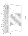
- topper edges 90, 92 and lateral edges 100, 102 of the transport material define pockets 104, 106 (only the right edge of the transport material and the right pocket are visible in FIG. 3 ; both edges and both pockets are visible in the embodiment of FIG. 4 ).
- the pockets may be empty as shown or may contain a material configured to encourage fluid flow toward openings 84, in which case the material can be the same transport material used elsewhere in the transport layer, but with directional properties that encourage fluid flow toward openings 84.
- the filler material is illustrated as fibrous mesh.
- Other suitable material architectures include open cell foam, open cell reticulated materials or other porous materials.
- One or more moisture sensors 110 responsive to the presence of liquid are positioned in or on the transport layer.
- the topper also includes a liquid impermeable base layer 114 beneath the transport layer.
- the base layer is integral with or bonded to transport layer 80, at least along their perimeters, to prevent unregulated escape of liquid through juncture 116 between the base layer and the transport layer.
- a material suitable for the base layer is polyurethane coated nylon.
- Topper assembly 64 also includes an air mover 120 in fluid communication with transport layer 80 and a reservoir 122. As seen in FIGS. 1 and 3 the air mover is an exhaust fan.
- a communication line 124 between moisture sensor 110 and controller 42 enables the controller to receive signals indicating the presence or absence of liquid in the transport layer.
- a second communication line 126 between controller 42 and fan 120 enables the controller to convey commands to the fan.
- communication between the sensor and the controller and between the controller and air mover can be accomplished without a physical connection, e.g. wirelessly.
- a conduit 140 has a first branch 142 extending from topper transport layer 80 to reservoir 122 and a second branch 144 extending from reservoir 122 to fan 120. Because fan 120 is an exhaust fan its operation suctions air away from the topper.
- the fan is therefore downstream of the topper, and thus downstream of the transport layer, with the reservoir residing streamwisely between the transport layer and the fan. More specifically, operation of the fan moves air, and any liquid which may be present in the transport layer, from the transport layer in the preferred direction established by the fluid flow directing properties of the material from which the transport layer is constructed.
- the air and liquid flow through conduit branch 142 to reservoir 122 such that the reservoir captures the liquid from the liquid transport layer.
- the air then flows through conduit branch 144.
- the fan creates suction in the transport layer sufficiently large to draw liquid through the transport layer in the preferred direction and cause the liquid to enter the reservoir.
- the topper component 66 of the illustrated topper assembly 64 also includes an optional liquid permeable cover layer 150 atop the transport layer.
- the cover layer in the illustration is liquid permeable by virtue of openings 152 penetrating through a material that is otherwise liquid impermeable, such as a polyurethane coated nylon.
- the openings are distributed over at least the longitudinal portion of the topper corresponding approximately to the expected position of an occupant's buttocks and torso.
- the presence of the cover layer is desirable if, for example, an occupant would find direct contact with the transport layer to be uncomfortable and/or if the transport layer could not be easily cleaned.
- the cover layer can then provide the required occupant comfort and cleanability. If a cover layer is used it is envisioned that the features which impart liquid permeability to the cover layer, e.g. openings 152, would be longitudinally and laterally coextensive with the transport material.
- FIG. 5 shows a variant of the transport layer in which the transport material is present in only that longitudinal portion of the transport layer corresponding approximately to the expected position of an occupant's buttocks and torso since this is the region where an incontinent occupant is most likely to deposit urine. If desired the transport material may be present in a larger region of the transport layer.
- laterally extending partitions 154 define compartments 156.
- the longitudinally outermost partitions extend to the edges of the transport layer.
- the longitudinally inner partitions are slightly foreshortened so that they terminate laterally inboard of the transport layer edges. Because of their orientation in the preferred direction of liquid transport, the partitions augment or reinforce the directional properties of the transport material.
- FIGS. 6A-6C shows a variant in which partitions are formed by pinching the transport material together.
- the pinch-formed partitions are designated 154A to distingush them from the panel style partitions 154 seen in other views.
- Each compartment has a dedicated opening 160 longitudinally bounded by the lateral extremities of two neighboring partitions. Because each compartment extends to left and right edges 90, 92, the filler material can also extend to the edges rather than being laterally foreshortened as in FIG. 3 .
- FIGS. 6A - 6C show longitudinally limited distribution of the transport material used in conjunction with partitions, the features (limited distribution and partitions) can be used individually.
- panel style partitions 154 could be used in lieu of the pinch-formed partitions 154A.
- sensor 110 monitors the transport layer for the presence of liquids such as urine, pus, blood, and spilled IV fluids to name just a few.
- Controller 42 receives data from the sensor indicating the presence or absence of liquid in the transport layer. If no liquid is present the controller commands fan 120 to operate in a climate management mode. In the climate management mode the fan operates at a speed sufficient to draw ambient air along a flowpath comprising openings 152 in cover layer 150 (if the cover layer is present) liquid transport layer 80, opening 84 (or openings 160 of FIG. 5B ), conduit branch 142, reservoir 122, and conduit branch 144.
- the support apparatus exhibits a microclimate control capability in which topper 66 serves as a microclimate control topper to control temperature and humidity in the immediate vicinity of a bed occupant.
- the controller commands fan 120 to operate in a liquid management mode.
- the fan operates at a speed sufficient to draw ambient air along the flowpath described above and to also create enough of a pressure gradient to draw the liquid through the transport layer in the preferred direction and cause the liquid to enter reservoir 122.
- the support apparatus exhibits both a microclimate control capability as described above and a liquid extraction capability to remove liquid that would otherwise puddle under the bed occupant and expose him or her to an elevated risk of skin tissue breakdown.
- FIGS. 7-8 show a "positive pressure” variant in which the air mover is a fan upstream of the transport layer and in which the reservoir is downstream of the transport layer.
- the fan or other air mover is configured to create pressure in the transport layer sufficiently large to force liquid that might be present in the transport layer through the transport layer in the preferred direction and cause the liquid to enter the reservoir.
- the variant of FIGS. 7-8 includes partitions oriented radially in the vicinity of air intake port 162 and extending laterally elsewhere in the transport layer.
- the variant of FIGS. 7-8 operates similarly to those of FIGS. 1-6 .
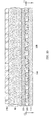
- FIG. 9 shows a variant of the topper which includes a dessicant layer 164 between transport layer 80 and the base layer 114.
- the dessicant layer helps remove residual moisture from the transport layer.
- FIGS. 10-11 shows a variant of the topper which includes not only dessicant layer 164 but also a spacer layer 166 beneath the dessicant layer.
- the spacer layer establishes a dessicant refresher flowpath 168.
- An air impeller not shown, forces air through the refresher flowpath to dry the dessicant, thus refreshing it and extending its useful life.
- the air impeller for the refresher flowpath may be the fan 120 already described or may be a distinct device.
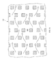
- FIG. 12 shows a negative pressure arrangement featuring nested compartments 156A, 156B each with three legs distributed longitudinally and alternately with the legs of the other compartment.
- FIG. 13 shows a similar positive pressure nested arrangement.
Landscapes
- Health & Medical Sciences (AREA)
- Nursing (AREA)
- Life Sciences & Earth Sciences (AREA)
- Animal Behavior & Ethology (AREA)
- General Health & Medical Sciences (AREA)
- Public Health (AREA)
- Veterinary Medicine (AREA)
- Invalid Beds And Related Equipment (AREA)
Abstract
Description
- The subject matter described herein relates to a support apparatus and an assembly having features for removing liquid deposited thereon and for affecting the climatic environment in the immediate vicinity thereof. In one example application the support apparatus includes a mattress and a condition management assembly, and the condition management assembly includes a topper assembly comprising a topper, an air mover and a liquid reservoir.
- Beds of the type used in hospitals, other health care facilities and residential health care settings include a mattress and may also include a topper which rests atop the mattress. Some toppers include microclimate control features which help regulate temperature and humidity in the immediate vicinity of the occupant of the bed in order to guard against breakdown of the occupant's skin tissue. Such toppers do not have the capacity to transport significant quantities of liquid away from the occupant's skin. Puddles of liquids may be present for a number of reasons such as incontinence, and pus or blood discharge from occupant wounds. The presence of liquid can be especially harmful to the occupant's skin. Accordingly, it is desirable to provide the capability to transport liquid away from the occupant's skin in addition to providing microclimate control.
- A assembly for a mattress comprises a liquid permeable cover layer, a liquid transport layer beneath the cover layer that transports liquid in a preferred direction, a liquid impermeable base layer beneath the transport layer, an air mover in fluid communication with the transport layer, and a reservoir positioned downstream of the liquid transport layer. Operation of the air mover moves air and liquid through the liquid transport layer in the preferred direction such that the reservoir captures liquid discharged from the liquid transport layer. A related support apparatus comprises a mattress and a condition management assembly atop the mattress. The condition management assembly includes the liquid transport layer, the liquid impermeable base layer, the air mover and the reservoir.
- The invention will now be further described by way of example with reference to the accompanying drawings, in which:
-
FIG. 1 is a simplified side elevation view of a hospital bed showing a "negative pressure" topper assembly and a related support apparatus. -
FIG. 2 is a plan view of the topper and other components of the topper assembly in which the topper component thereof includes an optional cover layer and in which a portion of the cover layer is broken away to expose a transport material of the transport layer. -
FIG. 3 is an enlarged view of a portion ofFIG. 1 showing details of a topper component of the topper assembly in which the topper includes the optional cover layer, a liquid transport layer and a base layer. -
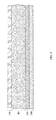
FIG. 4 is an end elevation view of the topper. -
FIG. 5 is a view similar toFIG. 2 showing a variant of the transport layer in which the transport material is present in only a limited longitudinal portion of the transport layer and in which partitions extend laterally across the transport layer and in which the transport material and longitudinally interior partitions do not extend to the lateral edges of the topper. -
FIGS. 6A - 6C are views showing a variant of the transport layer in which partitions are formed by pinching the transport material together and in which the transport material extends to the lateral edges of the topper. -
FIGS. 7-8 are a side elevation view and a plan view showing a "positive pressure" variant of the topper assembly. -
FIG. 9 is a side elevation view of a portion of a topper which includes a dessicant layer between the transport layer and the base layer. -
FIGS. 10-11 are a side elevation view similar toFIG. 9 and a plan view in which the topper includes a spacer layer beneath the dessicant layer. -
FIG. 12 is a plan view showing a negative pressure variant of the topper assembly featuring nested compartments each with three legs distributed longitudinally and alternately with the legs of the other compartment. -
FIG. 13 is a plan view similar toFIG. 12 showing a positive pressure variant. - Referring to
FIGS. 1-3 , ahospital bed 20 includes abase frame 22 and anelevatable frame 24. A lift system represented bylinks 26 renders the elevatable frame vertically moveable relative to the base frame. The bed extends longitudinally from a head end H to a foot end F and laterally from a left side L (seen in the plane ofFIG. 1 ) to a rightside R. Casters 28 extend from the base frame tofloor 40. Theelevatable frame 24 includes adeck 30 comprising longitudinally distributed deck segments. The deck segments include an upper body ortorso deck segment 32 corresponding approximately to an occupant's torso, aseat deck segment 34 corresponding approximately to an occupant's buttocks, athigh deck segment 36 corresponding approximately to an occupant's thighs, and acalf deck segment 38 corresponding approximately to an occupant's calves. The upper body, calf, and thigh deck segments are orientation adjustable through angles α, β and θ. The bed also includes acontroller 42 for controlling various functions of the bed. Longitudinal andlateral centerlines - The illustrated bed also includes a
support apparatus 60 which comprises amattress 62 for supporting a bed occupant and a condition management assembly for managing or regulating conditions in the immediate vicinity of the occupant. The condition management assembly may be integrated with the mattress, however is shown in the illustration as aseparate topper assembly 64 which includes atopper 66 which may be placed on the mattress or not depending on the needs of the occupant. Such independent toppers typically include a zipper or other means, not illustrated, for temporarily securing the topper to the mattress. The topper has left, right, head andfoot edges right edges - The topper includes a
liquid transport layer 80 comprising a liquidpermeable filler material 82, also referred to as a transport material. The transport material has numerousliquid transport channels 98 sized for accommodating liquid transport therethrough under the influence of a gas pressure gradient. The transport channels are oriented or otherwise configured to direct the liquid predominantly in a preferred direction such as the lateral direction and particularly in a laterally outboard direction. i.e. away fromlongitudinal centerline 46 and toward left and rightlateral edges FIGS. 1-3 the transport material does not extend laterally totopper edges topper edges lateral edges pockets 104, 106 (only the right edge of the transport material and the right pocket are visible inFIG. 3 ; both edges and both pockets are visible in the embodiment ofFIG. 4 ). The pockets may be empty as shown or may contain a material configured to encourage fluid flow towardopenings 84, in which case the material can be the same transport material used elsewhere in the transport layer, but with directional properties that encourage fluid flow towardopenings 84. The filler material is illustrated as fibrous mesh. Other suitable material architectures include open cell foam, open cell reticulated materials or other porous materials. One ormore moisture sensors 110 responsive to the presence of liquid are positioned in or on the transport layer. - The topper also includes a liquid
impermeable base layer 114 beneath the transport layer. The base layer is integral with or bonded to transportlayer 80, at least along their perimeters, to prevent unregulated escape of liquid throughjuncture 116 between the base layer and the transport layer. One example of a material suitable for the base layer is polyurethane coated nylon. -
Topper assembly 64 also includes anair mover 120 in fluid communication withtransport layer 80 and areservoir 122. As seen inFIGS. 1 and3 the air mover is an exhaust fan. Acommunication line 124 betweenmoisture sensor 110 andcontroller 42 enables the controller to receive signals indicating the presence or absence of liquid in the transport layer. Asecond communication line 126 betweencontroller 42 andfan 120 enables the controller to convey commands to the fan. Alternatively, communication between the sensor and the controller and between the controller and air mover can be accomplished without a physical connection, e.g. wirelessly. Aconduit 140 has afirst branch 142 extending fromtopper transport layer 80 toreservoir 122 and asecond branch 144 extending fromreservoir 122 tofan 120. Becausefan 120 is an exhaust fan its operation suctions air away from the topper. The fan is therefore downstream of the topper, and thus downstream of the transport layer, with the reservoir residing streamwisely between the transport layer and the fan. More specifically, operation of the fan moves air, and any liquid which may be present in the transport layer, from the transport layer in the preferred direction established by the fluid flow directing properties of the material from which the transport layer is constructed. The air and liquid flow throughconduit branch 142 toreservoir 122 such that the reservoir captures the liquid from the liquid transport layer. The air then flows throughconduit branch 144. The fan creates suction in the transport layer sufficiently large to draw liquid through the transport layer in the preferred direction and cause the liquid to enter the reservoir. - The
topper component 66 of the illustratedtopper assembly 64 also includes an optional liquidpermeable cover layer 150 atop the transport layer. The cover layer in the illustration is liquid permeable by virtue ofopenings 152 penetrating through a material that is otherwise liquid impermeable, such as a polyurethane coated nylon. The openings are distributed over at least the longitudinal portion of the topper corresponding approximately to the expected position of an occupant's buttocks and torso. The presence of the cover layer is desirable if, for example, an occupant would find direct contact with the transport layer to be uncomfortable and/or if the transport layer could not be easily cleaned. The cover layer can then provide the required occupant comfort and cleanability. If a cover layer is used it is envisioned that the features which impart liquid permeability to the cover layer,e.g. openings 152, would be longitudinally and laterally coextensive with the transport material. -
FIG. 5 shows a variant of the transport layer in which the transport material is present in only that longitudinal portion of the transport layer corresponding approximately to the expected position of an occupant's buttocks and torso since this is the region where an incontinent occupant is most likely to deposit urine. If desired the transport material may be present in a larger region of the transport layer. In the variant ofFIG. 5 laterally extendingpartitions 154 definecompartments 156. The longitudinally outermost partitions extend to the edges of the transport layer. The longitudinally inner partitions are slightly foreshortened so that they terminate laterally inboard of the transport layer edges. Because of their orientation in the preferred direction of liquid transport, the partitions augment or reinforce the directional properties of the transport material. -
FIGS. 6A-6C shows a variant in which partitions are formed by pinching the transport material together. The pinch-formed partitions are designated 154A to distingush them from thepanel style partitions 154 seen in other views. Each compartment has adedicated opening 160 longitudinally bounded by the lateral extremities of two neighboring partitions. Because each compartment extends to left andright edges FIG. 3 . AlthoughFIGS. 6A - 6C show longitudinally limited distribution of the transport material used in conjunction with partitions, the features (limited distribution and partitions) can be used individually. In addition,panel style partitions 154 could be used in lieu of the pinch-formedpartitions 154A. - In operation,
sensor 110 monitors the transport layer for the presence of liquids such as urine, pus, blood, and spilled IV fluids to name just a few.Controller 42 receives data from the sensor indicating the presence or absence of liquid in the transport layer. If no liquid is present the controller commandsfan 120 to operate in a climate management mode. In the climate management mode the fan operates at a speed sufficient to draw ambient air along aflowpath comprising openings 152 in cover layer 150 (if the cover layer is present)liquid transport layer 80, opening 84 (oropenings 160 ofFIG. 5B ),conduit branch 142,reservoir 122, andconduit branch 144. As a result, the support apparatus exhibits a microclimate control capability in whichtopper 66 serves as a microclimate control topper to control temperature and humidity in the immediate vicinity of a bed occupant. However if liquid is detected in the transport layer, the controller commandsfan 120 to operate in a liquid management mode. In the liquid management mode the fan operates at a speed sufficient to draw ambient air along the flowpath described above and to also create enough of a pressure gradient to draw the liquid through the transport layer in the preferred direction and cause the liquid to enterreservoir 122. As a result, the support apparatus exhibits both a microclimate control capability as described above and a liquid extraction capability to remove liquid that would otherwise puddle under the bed occupant and expose him or her to an elevated risk of skin tissue breakdown. - Because the air mover in the above described variants is downstream of the transport layer, these embodiments may be thought of as "negative pressure" variants.
FIGS. 7-8 show a "positive pressure" variant in which the air mover is a fan upstream of the transport layer and in which the reservoir is downstream of the transport layer. The fan or other air mover is configured to create pressure in the transport layer sufficiently large to force liquid that might be present in the transport layer through the transport layer in the preferred direction and cause the liquid to enter the reservoir. The variant ofFIGS. 7-8 includes partitions oriented radially in the vicinity ofair intake port 162 and extending laterally elsewhere in the transport layer. The variant ofFIGS. 7-8 operates similarly to those ofFIGS. 1-6 . -
FIG. 9 shows a variant of the topper which includes adessicant layer 164 betweentransport layer 80 and thebase layer 114. The dessicant layer helps remove residual moisture from the transport layer. -
FIGS. 10-11 shows a variant of the topper which includes not onlydessicant layer 164 but also aspacer layer 166 beneath the dessicant layer. The spacer layer establishes adessicant refresher flowpath 168. An air impeller, not shown, forces air through the refresher flowpath to dry the dessicant, thus refreshing it and extending its useful life. The air impeller for the refresher flowpath may be thefan 120 already described or may be a distinct device. -
FIG. 12 shows a negative pressure arrangement featuring nestedcompartments FIG. 13 shows a similar positive pressure nested arrangement. - Although this disclosure refers to specific embodiments, it will be understood by those skilled in the art that various changes in form and detail may be made.
Claims (13)
- An apparatus comprising an assembly for use with a mattress for managing environmental conditions comprising:a liquid permeable cover layer;a liquid transport layer beneath the cover layer, the liquid transport layer comprising a liquid permeable material having liquid flow channels sized to permit liquid transport therethrough and oriented to direct the liquid in a preferred direction;a liquid impermeable base layer beneath the transport layer;an air mover in fluid communication with the transport layer wherein operation of the air mover moves air and liquid through the liquid transport layer in the preferred direction; anda reservoir positioned downstream of the liquid transport layer such that the reservoir captures liquid discharged from the liquid transport layer.
- A support apparatus comprising:a mattress;a condition management assembly atop the mattress comprising:a liquid transport layer comprising a liquid permeable material having liquid flow channels sized for accommodating liquid transport therethrough and oriented to direct the liquid in a preferred direction;a liquid impermeable base layer beneath the transport layer;an air mover in fluid communication with the transport layer wherein operation of the air mover moves air and liquid through the liquid transport layer in the preferred direction; anda reservoir positioned downstream of the liquid transport layer such that the reservoir captures liquid discharged from the liquid transport layer.
- The apparatus of claim 2 including a liquid permeable cover layer atop the liquid transport layer.
- The assembly of either claim 1 or claim 3wherein openings penetrate through the cover layer, the cover layer being otherwise liquid impermeable.
- The apparatus of any preceding claim having a head end, a foot end spaced from the head end in a longitudinal direction, a left side, a right side spaced from the left side in a lateral direction and wherein the preferred direction is the lateral direction.
- The apparatus of claim 5 wherein the preferred direction is a laterally outboard direction.
- The apparatus of any preceding claim wherein the air mover is downstream of the transport layer, the reservoir is streamwisely between the transport layer and the air mover, and the air mover is configured to create suction in the transport layer sufficiently large to draw liquid through the transport layer in the preferred direction and cause the liquid to enter the reservoir.
- The apparatus of any one of claims 1 to 6 wherein the air mover is upstream of the transport layer, the reservoir is downstream of the transport layer and the air mover is configured to create pressure in the transport layer sufficiently large to force liquid through the transport layer in the preferred direction and cause the liquid to enter the reservoir.
- The apparatus of any preceding claim including a dessicant layer between the transport layer and the base layer.
- The apparatus of claim 9 including a spacer beneath the dessicant layer to establish a dessicant refresher flowpath.
- The apparatus of any preceding claim comprising a moisture sensor responsive to liquid present in the transport layer and a controller which produces a command for operating the blower in response to a moisture indication from the sensor.
- The apparatus of any preceding claim wherein the liquid transport layer includes partitions extending in the preferred direction.
- The apparatus of any preceding claim wherein the assembly is a topper assembly.
Applications Claiming Priority (1)
| Application Number | Priority Date | Filing Date | Title |
|---|---|---|---|
| US201261645361P | 2012-05-10 | 2012-05-10 |
Publications (3)
| Publication Number | Publication Date |
|---|---|
| EP2662064A2 true EP2662064A2 (en) | 2013-11-13 |
| EP2662064A3 EP2662064A3 (en) | 2014-04-09 |
| EP2662064B1 EP2662064B1 (en) | 2016-02-10 |
Family
ID=48325423
Family Applications (1)
| Application Number | Title | Priority Date | Filing Date |
|---|---|---|---|
| EP13166242.1A Active EP2662064B1 (en) | 2012-05-10 | 2013-05-02 | Occupant support apparatus and assembly with liquid removal and microclimate control capabilities |
Country Status (2)
| Country | Link |
|---|---|
| US (1) | US9009892B2 (en) |
| EP (1) | EP2662064B1 (en) |
Cited By (1)
| Publication number | Priority date | Publication date | Assignee | Title |
|---|---|---|---|---|
| US20260007556A1 (en) * | 2022-07-12 | 2026-01-08 | Umano Medical Inc. | Microclimate management systems |
Families Citing this family (43)
| Publication number | Priority date | Publication date | Assignee | Title |
|---|---|---|---|---|
| WO2009036077A1 (en) | 2007-09-10 | 2009-03-19 | Amerigon, Inc. | Operational control schemes for ventilated seat or bed assemblies |
| US9125497B2 (en) * | 2007-10-15 | 2015-09-08 | Gentherm Incorporated | Climate controlled bed assembly with intermediate layer |
| AU2009270757B2 (en) | 2008-07-18 | 2016-05-12 | Gentherm Incorporated | Climate controlled bed assembly |
| US8332975B2 (en) | 2009-08-31 | 2012-12-18 | Gentherm Incorporated | Climate-controlled topper member for medical beds |
| WO2012160502A1 (en) * | 2011-05-23 | 2012-11-29 | Koninklijke Philips Electronics N.V. | Temperature-controlled multi-zone mattress-style support |
| US20130212808A1 (en) * | 2012-02-21 | 2013-08-22 | Charles A. Lachenbruch | Topper with Targeted Fluid Flow Distribution |
| US9131780B2 (en) | 2012-02-14 | 2015-09-15 | Hill-Rom Services, Inc. | Topper with preferential fluid flow distribution |
| US9572433B2 (en) | 2012-08-15 | 2017-02-21 | Hill-Rom Services, Inc. | Systems and methods for directing fluid flow in a mattress |
| AU2013305806B2 (en) * | 2012-08-21 | 2017-10-19 | Arjo Ip Holding Ab | Patient transport device |
| PL2892488T3 (en) * | 2012-09-07 | 2019-01-31 | Huntleigh Technology Limited | Patient support devices with low air losses (LAL) |
| US9463124B2 (en) | 2013-01-15 | 2016-10-11 | Hill-Rom Services, Inc. | Microclimate system for a patient support apparatus |
| US9433300B2 (en) * | 2013-02-28 | 2016-09-06 | Hill-Rom Services, Inc. | Topper for a patient surface |
| US9711029B2 (en) | 2014-10-31 | 2017-07-18 | Hill-Rom Services, Inc. | Equipment, dressing and garment wireless connectivity to a patient bed |
| US9913770B2 (en) * | 2015-02-17 | 2018-03-13 | Hill-Rom Services, Inc. | Climate management topper with shape change actuators for regulating coolant distribution |
| US11559421B2 (en) | 2015-06-25 | 2023-01-24 | Hill-Rom Services, Inc. | Protective dressing with reusable phase-change material cooling insert |
| US10624804B2 (en) * | 2015-08-18 | 2020-04-21 | Hill-Rom Services, Inc. | Microclimate management airflow control based on incontinence detection |
| ES2982004T3 (en) * | 2017-11-21 | 2024-10-14 | Vincenzo Buoninfante | Mattress |
| US11246775B2 (en) | 2017-12-28 | 2022-02-15 | Stryker Corporation | Patient turning device for a patient support apparatus |
| US11173085B2 (en) | 2017-12-28 | 2021-11-16 | Stryker Corporation | Mattress cover for a mattress providing rotation therapy to a patient |
| US11583437B2 (en) | 2018-02-06 | 2023-02-21 | Aspen Surgical Products, Inc. | Reusable warming blanket with phase change material |
| US10456084B1 (en) * | 2018-08-02 | 2019-10-29 | Yung Hsiang Information Management, Co. Ltd | Intelligent hospital bed |
| USD879966S1 (en) | 2018-09-28 | 2020-03-31 | Stryker Corporation | Crib assembly |
| USD888963S1 (en) | 2018-09-28 | 2020-06-30 | Stryker Corporation | Cover assembly for a patient support |
| USD977109S1 (en) | 2018-09-28 | 2023-01-31 | Stryker Corporation | Crib assembly for a patient support |
| USD877915S1 (en) | 2018-09-28 | 2020-03-10 | Stryker Corporation | Crib assembly |
| USD888964S1 (en) | 2018-09-28 | 2020-06-30 | Stryker Corporation | Crib assembly for a patient support |
| USD901940S1 (en) | 2018-09-28 | 2020-11-17 | Stryker Corporation | Patient support |
| USD888962S1 (en) | 2018-09-28 | 2020-06-30 | Stryker Corporation | Cover assembly for a patient support |
| USD892159S1 (en) | 2018-10-31 | 2020-08-04 | Stryker Corporation | Display screen with animated graphical user interface |
| USD894226S1 (en) | 2018-10-31 | 2020-08-25 | Stryker Corporation | Display screen or portion thereof with graphical user interface |
| USD894223S1 (en) | 2018-10-31 | 2020-08-25 | Stryker Corporation | Display screen with animated graphical user interface |
| USD890914S1 (en) | 2018-10-31 | 2020-07-21 | Stryker Corporation | Pump |
| USD894957S1 (en) | 2018-10-31 | 2020-09-01 | Stryker Corporation | Display screen or portion thereof with graphical user interface |
| USD894956S1 (en) | 2018-10-31 | 2020-09-01 | Stryker Corporation | Display screen or portion thereof with graphical user interface |
| USD893543S1 (en) | 2018-10-31 | 2020-08-18 | Stryker Corporation | Display screen with graphical user interface |
| US12121479B1 (en) | 2021-04-16 | 2024-10-22 | Turn Medical, LLC | Strap and release system |
| US12458551B1 (en) | 2021-04-16 | 2025-11-04 | Turn Medical, LLC | Stowable inner leg supports |
| US12403057B1 (en) | 2021-04-16 | 2025-09-02 | Turn Medical, LLC | Proning face pack |
| US12226356B1 (en) | 2021-04-16 | 2025-02-18 | Turn Medical, LLC | Adjustable posterior head support |
| US12042440B1 (en) | 2021-04-16 | 2024-07-23 | Turn Medical, LLC | Stowable patient supports |
| US20230165392A1 (en) * | 2021-11-30 | 2023-06-01 | Dreamwell, Ltd. | Bedding components including a desiccant |
| US12414885B2 (en) * | 2022-03-14 | 2025-09-16 | Payman Zamirpour | Medical bed and multifunctional mattress assembly |
| EP4687802A2 (en) * | 2023-03-31 | 2026-02-11 | Hill-Rom Services, Inc. | Mattress with low-pressure high-flow moisture management |
Family Cites Families (21)
| Publication number | Priority date | Publication date | Assignee | Title |
|---|---|---|---|---|
| GB814544A (en) * | 1956-05-29 | 1959-06-10 | Frederick Wilfred Knowles | Sanitary bed |
| US3757356A (en) | 1972-07-13 | 1973-09-11 | H Freeman | Therapeutic bed pan |
| US4620333A (en) * | 1985-05-21 | 1986-11-04 | Ritter Russell F | Incontinent bed facility |
| US4870710A (en) * | 1989-03-03 | 1989-10-03 | Richard Hartmann | Body-liquid collecting and mattress protecting apparatus |
| US5269030A (en) * | 1991-11-13 | 1993-12-14 | Ssi Medical Services, Inc. | Apparatus and method for managing waste from patient care, maintenance, and treatment |
| US5244457A (en) * | 1992-03-23 | 1993-09-14 | The Kendall Company | Vented wound dressing |
| US5380278A (en) * | 1992-06-26 | 1995-01-10 | Mombrinie; Pierre | Liquid cleansing and evacuation method and apparatus for use in surgical procedures |
| WO1995008936A1 (en) | 1993-09-30 | 1995-04-06 | Graebe Robert H | Ventilated access interface and cushion support system |
| US5549584A (en) * | 1994-02-14 | 1996-08-27 | The Kendall Company | Apparatus for removing fluid from a wound |
| US5827246A (en) * | 1996-02-28 | 1998-10-27 | Tecnol Medical Products, Inc. | Vacuum pad for collecting potentially hazardous fluids |
| US6102073A (en) * | 1998-07-13 | 2000-08-15 | Williams; Kevin M. | Fluid-collecting receptacle |
| US6892734B1 (en) * | 2000-10-19 | 2005-05-17 | Thomas R. Schleicher | Wound care suspension system |
| US6450995B1 (en) * | 2001-01-10 | 2002-09-17 | Indira C. Prabhakar | Diaper for an incontinent person |
| TWI265024B (en) * | 2003-03-10 | 2006-11-01 | Hitachi Ltd | Automatic urine disposal device and urine receptacle used therefor |
| JP4283631B2 (en) * | 2003-09-30 | 2009-06-24 | 株式会社日立製作所 | Automatic urination processing apparatus and urine receiver used therefor |
| US7901389B2 (en) * | 2004-03-03 | 2011-03-08 | Avec Scientific Design Corporation | Liquid removal method and apparatus for surgical procedures |
| US7469436B2 (en) | 2004-04-30 | 2008-12-30 | Hill-Rom Services, Inc. | Pressure relief surface |
| US20060015080A1 (en) * | 2004-07-15 | 2006-01-19 | Michael Mahnensmith | Fluid collection and aspiration unit for management of urinary incontinence |
| US7975335B2 (en) | 2006-05-09 | 2011-07-12 | Hill-Rom Services, Inc. | Pulmonary mattress |
| US7914611B2 (en) * | 2006-05-11 | 2011-03-29 | Kci Licensing, Inc. | Multi-layered support system |
| US8607380B2 (en) * | 2011-03-02 | 2013-12-17 | Inteplast Group, Ltd. | Portable lightweight bed |
-
2012
- 2012-09-07 US US13/606,417 patent/US9009892B2/en active Active
-
2013
- 2013-05-02 EP EP13166242.1A patent/EP2662064B1/en active Active
Non-Patent Citations (1)
| Title |
|---|
| None |
Cited By (1)
| Publication number | Priority date | Publication date | Assignee | Title |
|---|---|---|---|---|
| US20260007556A1 (en) * | 2022-07-12 | 2026-01-08 | Umano Medical Inc. | Microclimate management systems |
Also Published As
| Publication number | Publication date |
|---|---|
| EP2662064A3 (en) | 2014-04-09 |
| US9009892B2 (en) | 2015-04-21 |
| EP2662064B1 (en) | 2016-02-10 |
| US20130298330A1 (en) | 2013-11-14 |
Similar Documents
| Publication | Publication Date | Title |
|---|---|---|
| US9009892B2 (en) | Occupant support and topper assembly with liquid removal and microclimate control capabilities | |
| US10172470B1 (en) | Multi-layer support system | |
| US20110283459A1 (en) | Mattress, in particular for use in the care and hospital sector | |
| EP2804508B1 (en) | System for support and thermal control | |
| EP2772238B1 (en) | Sensors in a mattress cover | |
| KR102113891B1 (en) | Multi-layered patient support cover sheet system | |
| US20130205506A1 (en) | Topper with Preferential Fluid Flow Distribution | |
| JP2016523585A (en) | Apparatus including absorbent article and exhaust apparatus, and method of operation of exhaust article acting on humid and warm atmosphere using exhaust apparatus | |
| US20110010855A1 (en) | Therapy and Low Air Loss Universal Coverlet | |
| JP6830929B2 (en) | Patient transport device | |
| WO2014036472A1 (en) | Multi-layered patient support cover sheet system |
Legal Events
| Date | Code | Title | Description |
|---|---|---|---|
| PUAI | Public reference made under article 153(3) epc to a published international application that has entered the european phase |
Free format text: ORIGINAL CODE: 0009012 |
|
| AK | Designated contracting states |
Kind code of ref document: A2 Designated state(s): AL AT BE BG CH CY CZ DE DK EE ES FI FR GB GR HR HU IE IS IT LI LT LU LV MC MK MT NL NO PL PT RO RS SE SI SK SM TR |
|
| AX | Request for extension of the european patent |
Extension state: BA ME |
|
| PUAL | Search report despatched |
Free format text: ORIGINAL CODE: 0009013 |
|
| AK | Designated contracting states |
Kind code of ref document: A3 Designated state(s): AL AT BE BG CH CY CZ DE DK EE ES FI FR GB GR HR HU IE IS IT LI LT LU LV MC MK MT NL NO PL PT RO RS SE SI SK SM TR |
|
| AX | Request for extension of the european patent |
Extension state: BA ME |
|
| RIC1 | Information provided on ipc code assigned before grant |
Ipc: A61G 7/057 20060101AFI20140228BHEP Ipc: A61G 7/02 20060101ALN20140228BHEP |
|
| 17P | Request for examination filed |
Effective date: 20141008 |
|
| RBV | Designated contracting states (corrected) |
Designated state(s): AL AT BE BG CH CY CZ DE DK EE ES FI FR GB GR HR HU IE IS IT LI LT LU LV MC MK MT NL NO PL PT RO RS SE SI SK SM TR |
|
| RIC1 | Information provided on ipc code assigned before grant |
Ipc: A61G 7/02 20060101ALN20150420BHEP Ipc: A61G 7/057 20060101AFI20150420BHEP |
|
| GRAP | Despatch of communication of intention to grant a patent |
Free format text: ORIGINAL CODE: EPIDOSNIGR1 |
|
| INTG | Intention to grant announced |
Effective date: 20150702 |
|
| GRAJ | Information related to disapproval of communication of intention to grant by the applicant or resumption of examination proceedings by the epo deleted |
Free format text: ORIGINAL CODE: EPIDOSDIGR1 |
|
| GRAP | Despatch of communication of intention to grant a patent |
Free format text: ORIGINAL CODE: EPIDOSNIGR1 |
|
| INTG | Intention to grant announced |
Effective date: 20150807 |
|
| GRAS | Grant fee paid |
Free format text: ORIGINAL CODE: EPIDOSNIGR3 |
|
| GRAA | (expected) grant |
Free format text: ORIGINAL CODE: 0009210 |
|
| RIN1 | Information on inventor provided before grant (corrected) |
Inventor name: LACHENBRUCH, CHARLES A. Inventor name: RECEVEUR, TIMOTHY JOSEPH |
|
| AK | Designated contracting states |
Kind code of ref document: B1 Designated state(s): AL AT BE BG CH CY CZ DE DK EE ES FI FR GB GR HR HU IE IS IT LI LT LU LV MC MK MT NL NO PL PT RO RS SE SI SK SM TR |
|
| REG | Reference to a national code |
Ref country code: GB Ref legal event code: FG4D |
|
| REG | Reference to a national code |
Ref country code: AT Ref legal event code: REF Ref document number: 774284 Country of ref document: AT Kind code of ref document: T Effective date: 20160215 Ref country code: CH Ref legal event code: EP |
|
| REG | Reference to a national code |
Ref country code: IE Ref legal event code: FG4D |
|
| REG | Reference to a national code |
Ref country code: DE Ref legal event code: R096 Ref document number: 602013004979 Country of ref document: DE |
|
| REG | Reference to a national code |
Ref country code: FR Ref legal event code: PLFP Year of fee payment: 4 |
|
| REG | Reference to a national code |
Ref country code: LT Ref legal event code: MG4D |
|
| REG | Reference to a national code |
Ref country code: NL Ref legal event code: MP Effective date: 20160210 |
|
| REG | Reference to a national code |
Ref country code: AT Ref legal event code: MK05 Ref document number: 774284 Country of ref document: AT Kind code of ref document: T Effective date: 20160210 |
|
| PG25 | Lapsed in a contracting state [announced via postgrant information from national office to epo] |
Ref country code: ES Free format text: LAPSE BECAUSE OF FAILURE TO SUBMIT A TRANSLATION OF THE DESCRIPTION OR TO PAY THE FEE WITHIN THE PRESCRIBED TIME-LIMIT Effective date: 20160210 Ref country code: HR Free format text: LAPSE BECAUSE OF FAILURE TO SUBMIT A TRANSLATION OF THE DESCRIPTION OR TO PAY THE FEE WITHIN THE PRESCRIBED TIME-LIMIT Effective date: 20160210 Ref country code: NO Free format text: LAPSE BECAUSE OF FAILURE TO SUBMIT A TRANSLATION OF THE DESCRIPTION OR TO PAY THE FEE WITHIN THE PRESCRIBED TIME-LIMIT Effective date: 20160510 Ref country code: FI Free format text: LAPSE BECAUSE OF FAILURE TO SUBMIT A TRANSLATION OF THE DESCRIPTION OR TO PAY THE FEE WITHIN THE PRESCRIBED TIME-LIMIT Effective date: 20160210 Ref country code: IT Free format text: LAPSE BECAUSE OF FAILURE TO SUBMIT A TRANSLATION OF THE DESCRIPTION OR TO PAY THE FEE WITHIN THE PRESCRIBED TIME-LIMIT Effective date: 20160210 Ref country code: GR Free format text: LAPSE BECAUSE OF FAILURE TO SUBMIT A TRANSLATION OF THE DESCRIPTION OR TO PAY THE FEE WITHIN THE PRESCRIBED TIME-LIMIT Effective date: 20160511 |
|
| PG25 | Lapsed in a contracting state [announced via postgrant information from national office to epo] |
Ref country code: NL Free format text: LAPSE BECAUSE OF FAILURE TO SUBMIT A TRANSLATION OF THE DESCRIPTION OR TO PAY THE FEE WITHIN THE PRESCRIBED TIME-LIMIT Effective date: 20160210 Ref country code: PL Free format text: LAPSE BECAUSE OF FAILURE TO SUBMIT A TRANSLATION OF THE DESCRIPTION OR TO PAY THE FEE WITHIN THE PRESCRIBED TIME-LIMIT Effective date: 20160210 Ref country code: LV Free format text: LAPSE BECAUSE OF FAILURE TO SUBMIT A TRANSLATION OF THE DESCRIPTION OR TO PAY THE FEE WITHIN THE PRESCRIBED TIME-LIMIT Effective date: 20160210 Ref country code: IS Free format text: LAPSE BECAUSE OF FAILURE TO SUBMIT A TRANSLATION OF THE DESCRIPTION OR TO PAY THE FEE WITHIN THE PRESCRIBED TIME-LIMIT Effective date: 20160610 Ref country code: BE Free format text: LAPSE BECAUSE OF NON-PAYMENT OF DUE FEES Effective date: 20160531 Ref country code: LT Free format text: LAPSE BECAUSE OF FAILURE TO SUBMIT A TRANSLATION OF THE DESCRIPTION OR TO PAY THE FEE WITHIN THE PRESCRIBED TIME-LIMIT Effective date: 20160210 Ref country code: SE Free format text: LAPSE BECAUSE OF FAILURE TO SUBMIT A TRANSLATION OF THE DESCRIPTION OR TO PAY THE FEE WITHIN THE PRESCRIBED TIME-LIMIT Effective date: 20160210 Ref country code: PT Free format text: LAPSE BECAUSE OF FAILURE TO SUBMIT A TRANSLATION OF THE DESCRIPTION OR TO PAY THE FEE WITHIN THE PRESCRIBED TIME-LIMIT Effective date: 20160613 Ref country code: AT Free format text: LAPSE BECAUSE OF FAILURE TO SUBMIT A TRANSLATION OF THE DESCRIPTION OR TO PAY THE FEE WITHIN THE PRESCRIBED TIME-LIMIT Effective date: 20160210 Ref country code: RS Free format text: LAPSE BECAUSE OF FAILURE TO SUBMIT A TRANSLATION OF THE DESCRIPTION OR TO PAY THE FEE WITHIN THE PRESCRIBED TIME-LIMIT Effective date: 20160210 |
|
| PG25 | Lapsed in a contracting state [announced via postgrant information from national office to epo] |
Ref country code: DK Free format text: LAPSE BECAUSE OF FAILURE TO SUBMIT A TRANSLATION OF THE DESCRIPTION OR TO PAY THE FEE WITHIN THE PRESCRIBED TIME-LIMIT Effective date: 20160210 Ref country code: EE Free format text: LAPSE BECAUSE OF FAILURE TO SUBMIT A TRANSLATION OF THE DESCRIPTION OR TO PAY THE FEE WITHIN THE PRESCRIBED TIME-LIMIT Effective date: 20160210 |
|
| REG | Reference to a national code |
Ref country code: DE Ref legal event code: R097 Ref document number: 602013004979 Country of ref document: DE |
|
| PG25 | Lapsed in a contracting state [announced via postgrant information from national office to epo] |
Ref country code: CZ Free format text: LAPSE BECAUSE OF FAILURE TO SUBMIT A TRANSLATION OF THE DESCRIPTION OR TO PAY THE FEE WITHIN THE PRESCRIBED TIME-LIMIT Effective date: 20160210 Ref country code: RO Free format text: LAPSE BECAUSE OF FAILURE TO SUBMIT A TRANSLATION OF THE DESCRIPTION OR TO PAY THE FEE WITHIN THE PRESCRIBED TIME-LIMIT Effective date: 20160210 Ref country code: SM Free format text: LAPSE BECAUSE OF FAILURE TO SUBMIT A TRANSLATION OF THE DESCRIPTION OR TO PAY THE FEE WITHIN THE PRESCRIBED TIME-LIMIT Effective date: 20160210 Ref country code: SK Free format text: LAPSE BECAUSE OF FAILURE TO SUBMIT A TRANSLATION OF THE DESCRIPTION OR TO PAY THE FEE WITHIN THE PRESCRIBED TIME-LIMIT Effective date: 20160210 |
|
| PLBE | No opposition filed within time limit |
Free format text: ORIGINAL CODE: 0009261 |
|
| STAA | Information on the status of an ep patent application or granted ep patent |
Free format text: STATUS: NO OPPOSITION FILED WITHIN TIME LIMIT |
|
| PG25 | Lapsed in a contracting state [announced via postgrant information from national office to epo] |
Ref country code: LU Free format text: LAPSE BECAUSE OF FAILURE TO SUBMIT A TRANSLATION OF THE DESCRIPTION OR TO PAY THE FEE WITHIN THE PRESCRIBED TIME-LIMIT Effective date: 20160502 Ref country code: BE Free format text: LAPSE BECAUSE OF FAILURE TO SUBMIT A TRANSLATION OF THE DESCRIPTION OR TO PAY THE FEE WITHIN THE PRESCRIBED TIME-LIMIT Effective date: 20160210 |
|
| REG | Reference to a national code |
Ref country code: CH Ref legal event code: PL |
|
| 26N | No opposition filed |
Effective date: 20161111 |
|
| PG25 | Lapsed in a contracting state [announced via postgrant information from national office to epo] |
Ref country code: LI Free format text: LAPSE BECAUSE OF NON-PAYMENT OF DUE FEES Effective date: 20160531 Ref country code: CH Free format text: LAPSE BECAUSE OF NON-PAYMENT OF DUE FEES Effective date: 20160531 |
|
| REG | Reference to a national code |
Ref country code: IE Ref legal event code: MM4A |
|
| PG25 | Lapsed in a contracting state [announced via postgrant information from national office to epo] |
Ref country code: SI Free format text: LAPSE BECAUSE OF FAILURE TO SUBMIT A TRANSLATION OF THE DESCRIPTION OR TO PAY THE FEE WITHIN THE PRESCRIBED TIME-LIMIT Effective date: 20160210 Ref country code: BG Free format text: LAPSE BECAUSE OF FAILURE TO SUBMIT A TRANSLATION OF THE DESCRIPTION OR TO PAY THE FEE WITHIN THE PRESCRIBED TIME-LIMIT Effective date: 20160510 |
|
| REG | Reference to a national code |
Ref country code: FR Ref legal event code: PLFP Year of fee payment: 5 |
|
| PG25 | Lapsed in a contracting state [announced via postgrant information from national office to epo] |
Ref country code: IE Free format text: LAPSE BECAUSE OF NON-PAYMENT OF DUE FEES Effective date: 20160502 |
|
| REG | Reference to a national code |
Ref country code: FR Ref legal event code: PLFP Year of fee payment: 6 |
|
| PG25 | Lapsed in a contracting state [announced via postgrant information from national office to epo] |
Ref country code: CY Free format text: LAPSE BECAUSE OF FAILURE TO SUBMIT A TRANSLATION OF THE DESCRIPTION OR TO PAY THE FEE WITHIN THE PRESCRIBED TIME-LIMIT Effective date: 20160210 Ref country code: HU Free format text: LAPSE BECAUSE OF FAILURE TO SUBMIT A TRANSLATION OF THE DESCRIPTION OR TO PAY THE FEE WITHIN THE PRESCRIBED TIME-LIMIT; INVALID AB INITIO Effective date: 20130502 |
|
| PG25 | Lapsed in a contracting state [announced via postgrant information from national office to epo] |
Ref country code: MC Free format text: LAPSE BECAUSE OF FAILURE TO SUBMIT A TRANSLATION OF THE DESCRIPTION OR TO PAY THE FEE WITHIN THE PRESCRIBED TIME-LIMIT Effective date: 20160210 Ref country code: MT Free format text: LAPSE BECAUSE OF NON-PAYMENT OF DUE FEES Effective date: 20160531 Ref country code: MK Free format text: LAPSE BECAUSE OF FAILURE TO SUBMIT A TRANSLATION OF THE DESCRIPTION OR TO PAY THE FEE WITHIN THE PRESCRIBED TIME-LIMIT Effective date: 20160210 Ref country code: TR Free format text: LAPSE BECAUSE OF FAILURE TO SUBMIT A TRANSLATION OF THE DESCRIPTION OR TO PAY THE FEE WITHIN THE PRESCRIBED TIME-LIMIT Effective date: 20160210 |
|
| PG25 | Lapsed in a contracting state [announced via postgrant information from national office to epo] |
Ref country code: AL Free format text: LAPSE BECAUSE OF FAILURE TO SUBMIT A TRANSLATION OF THE DESCRIPTION OR TO PAY THE FEE WITHIN THE PRESCRIBED TIME-LIMIT Effective date: 20160210 |
|
| REG | Reference to a national code |
Ref country code: DE Ref legal event code: R082 Ref document number: 602013004979 Country of ref document: DE Representative=s name: PRUEFER & PARTNER MBB PATENTANWAELTE RECHTSANW, DE |
|
| PGFP | Annual fee paid to national office [announced via postgrant information from national office to epo] |
Ref country code: DE Payment date: 20250423 Year of fee payment: 13 |
|
| PGFP | Annual fee paid to national office [announced via postgrant information from national office to epo] |
Ref country code: FR Payment date: 20250423 Year of fee payment: 13 |
|
| PGFP | Annual fee paid to national office [announced via postgrant information from national office to epo] |
Ref country code: GB Payment date: 20260317 Year of fee payment: 14 |