EP2662012B1 - Vacuum cleaner - Google Patents
Vacuum cleaner Download PDFInfo
- Publication number
- EP2662012B1 EP2662012B1 EP13166688.5A EP13166688A EP2662012B1 EP 2662012 B1 EP2662012 B1 EP 2662012B1 EP 13166688 A EP13166688 A EP 13166688A EP 2662012 B1 EP2662012 B1 EP 2662012B1
- Authority
- EP
- European Patent Office
- Prior art keywords
- cord
- power cord
- guide
- cleaner
- reel
- Prior art date
- Legal status (The legal status is an assumption and is not a legal conclusion. Google has not performed a legal analysis and makes no representation as to the accuracy of the status listed.)
- Not-in-force
Links
- 239000000428 dust Substances 0.000 description 13
- 239000000470 constituent Substances 0.000 description 12
- 230000007423 decrease Effects 0.000 description 11
- 230000004308 accommodation Effects 0.000 description 9
- 230000007246 mechanism Effects 0.000 description 9
- 238000004140 cleaning Methods 0.000 description 8
- 238000004804 winding Methods 0.000 description 7
- 239000000356 contaminant Substances 0.000 description 6
- 230000008859 change Effects 0.000 description 5
- 230000001965 increasing effect Effects 0.000 description 4
- 230000002265 prevention Effects 0.000 description 4
- 230000008878 coupling Effects 0.000 description 3
- 238000010168 coupling process Methods 0.000 description 3
- 238000005859 coupling reaction Methods 0.000 description 3
- 230000000694 effects Effects 0.000 description 3
- 230000002708 enhancing effect Effects 0.000 description 2
- 230000007257 malfunction Effects 0.000 description 2
- 230000003252 repetitive effect Effects 0.000 description 2
- 241001508691 Martes zibellina Species 0.000 description 1
- 230000000903 blocking effect Effects 0.000 description 1
- 230000003139 buffering effect Effects 0.000 description 1
- 230000015556 catabolic process Effects 0.000 description 1
- 230000008094 contradictory effect Effects 0.000 description 1
- 230000003247 decreasing effect Effects 0.000 description 1
- 238000006731 degradation reaction Methods 0.000 description 1
- 238000001914 filtration Methods 0.000 description 1
- 230000005484 gravity Effects 0.000 description 1
- 238000009434 installation Methods 0.000 description 1
- 238000004519 manufacturing process Methods 0.000 description 1
- 239000000463 material Substances 0.000 description 1
- 229920001296 polysiloxane Polymers 0.000 description 1
- 238000011084 recovery Methods 0.000 description 1
- 230000002441 reversible effect Effects 0.000 description 1
Images

Classifications
-
- A—HUMAN NECESSITIES
- A47—FURNITURE; DOMESTIC ARTICLES OR APPLIANCES; COFFEE MILLS; SPICE MILLS; SUCTION CLEANERS IN GENERAL
- A47L—DOMESTIC WASHING OR CLEANING; SUCTION CLEANERS IN GENERAL
- A47L9/00—Details or accessories of suction cleaners, e.g. mechanical means for controlling the suction or for effecting pulsating action; Storing devices specially adapted to suction cleaners or parts thereof; Carrying-vehicles specially adapted for suction cleaners
- A47L9/28—Installation of the electric equipment, e.g. adaptation or attachment to the suction cleaner; Controlling suction cleaners by electric means
-
- A—HUMAN NECESSITIES
- A47—FURNITURE; DOMESTIC ARTICLES OR APPLIANCES; COFFEE MILLS; SPICE MILLS; SUCTION CLEANERS IN GENERAL
- A47L—DOMESTIC WASHING OR CLEANING; SUCTION CLEANERS IN GENERAL
- A47L9/00—Details or accessories of suction cleaners, e.g. mechanical means for controlling the suction or for effecting pulsating action; Storing devices specially adapted to suction cleaners or parts thereof; Carrying-vehicles specially adapted for suction cleaners
- A47L9/26—Incorporation of winding devices for electric cables
Definitions
- the present invention relates to a vacuum cleaner, and more particularly, to a vacuum cleaner having an improved structure for pulling in and withdrawing a power cord, thereby providing user convenience and enhancing durability.
- the present invention relates to a vacuum cleaner preventing a power cord from tangling when the power cord is retracted, thereby enhancing reliability.
- the vacuum cleaner is a device suctioning foreign materials along with air and filtering them out in the body of the vacuum cleaner.
- the vacuum cleaner generally includes a body having a motor installed therein to generate suction force, a suction nozzle to suction foreign matters and air from the floor surface, and a dust collector to filter out foreign matters.
- vacuum cleaner will be simply referred to as cleaner for convenience of description.
- the cleaner drives the motor using an external power applied thereto, and is therefore provided with a power cord to which the external power is connect.
- a vacuum cleaner having a self-charging battery.
- cleaners with a power cord are widely distributed since they are capable of continuously generating sufficient suction force through sable supply of electrical power.
- the cleaner may need to move a very long distance from a wall outlet.
- it is tiresome to frequently plug in the power cord to wall outlets positioned at different places.
- the power cord is elongated to have a very long length. Exposing such a power cord to the outside of the body after completion of cleaning may result in difficult handling and storing of the cleaner and degradation in aesthetics of the external appearance of the cleaner.
- the cord reel which is used to keep the power cord in a wound state, is a device to automatically wind the power cord using elastic force.
- a user may withdraw the power cord from the cleaner body to perform cleaning and allow the power cord to be automatically retracted into the body by releasing the lock of the cord reel when operation with the cleaner is completed. That is, when locking by the cord reel locker is released, the power cord may be automatically retracted into the body. Accordingly, the user does not need to manually re-place or re-wind the drawn out power cord in the body.
- the power cord is closely wound around the middle portion of the cord reel.
- the power cord may often be wound not around the middle portion of the cord reel, but around portions near the sides of the cord reel.
- the power cord may be entangled on the cord reel. That is, the power cord is not sequentially wound. Thereby, the entire power cord may not be sufficiently wound. This results from a portion of the power cord filling the whole space for the power cord and thus blocking rotation of the cord reel even when the power cord is not completely wound.
- the user needs to make arduous efforts to repeat pulling and releasing of the power cord several times to disentangle the power cord.
- the power cord that is not completely retracted automatically results in inconvenience to the user by causing the user to push the unwound portion of the power cord back into the cleaner body.
- the power cord when the power cord is quickly polled into the cleaner body, it hits the cord introduction inlet, and thereby may cause damage to the cord introduction inlet. That is, the cord introduction inlet may be damaged if the cord reel locker is released after completion of cleaning with the cord introduction inlet misaligned with the power cord. For this reason, it is highly possible that the power cord is wound not at the middle portion of the cord reel, but at a portion biased to one side of the cord reel.
- the cord reel locker functions to prevent the power cord from being automatically retracted after the power cord is pulled out and released by the user.
- a cord reel locker blocks rotation of the cord reel, not the movement of the power cord. That is, for the conventional cord reel locker, a user needs to overcome the elastic force of the cord reel locker and the elastic force of the cord reel to withdraw the power cord. In addition, once the withdrawal of the power cord is stopped, rotation of the cord reel is prevented by the elastic recovery of the cord reel locker. Thereby, the power cord is set in the drawn out state.
- the user may release the cord reel locker to allow the power cord to be retracted.
- the cord reel elastically rotates to wind the power cord around the cord reel to cause the power cord to be automatically retractedto the body.
- a conventional structure has a following problem.
- a user may release the locker to allow the power cord to be retracted.
- the user may apply the locker when power cord is not completely retracted. That is, the user may terminate the pressed state of the lock release button of the locker before the power cord is completely retracted.
- a large portion of the power cord may fail to be wound around the cord reel due to the inertial force of the power cord retracting into the body of the cleaner. This is because rotation of the cord reel is prevented directly by the locker, while the power cord is retracted into the body by inertial force. This means that a majority of the power cord may be retracted into the body without being directly wound around the cord reel. For this reason, the power cord may be very loosely wound around the cord reel or be entangled in the body.
- the inertia of the retracting power cord may cause the power cord to hit and damage the inside of the body.
- KR 100354605 B1 discloses a cleaner comprising a cleaner body with a power cord which can be wounded onto a cord real assembly comprising a cord reel, wherein the cleaner further comprises a direction guide assembly formed to a have a width narrowing in one direction to facilitate the introduction of the power cord into the cleaner.
- the present invention is directed to a cleaner that substantially obviates one or more problems due to limitations and disadvantages of the related art.
- An object of the present invention is to provide a cleaner having enhanced durability and reliability regarding a structure for drawing out and retracting of a power cord.
- Another object of the present invention is to provide a cleaner which ensures sufficient winding of the power cord by allowing a power cord to be wound around the central portion of a cord reel assembly and is thus convenient to use.
- Another object of the present invention is to provide a cleaner securing an improved durability by preventing damage to a portion of a cleaner body through which a power cord is introduced into the cleaner body.
- Another object of the present invention is to provide a cleaner which may reduce impact between a power cord and the cleaner which occurs when the power cord is retracted.
- Another object of the present invention is to provide a cleaner allowing a user to conveniently use a cord locker.
- Another object of the present invention is to provide a cleaner in which a power cord is directly held to block automatic retraction of the power cord to thereby prevent malfunction of a cord reel assembly and entanglement of the power cord and facilitate repetitive use of a cord locker.
- Another object of the present invention is to provide a cleaner which ensures sufficient time and distance needed to stop movement of a power cord, thereby preventing occurrence of impact due to sudden stop of the power cord.
- Another object of the present invention is to provide a cleaner that may effectively prevent user misrecognition of the position and use of a lock release button for releasing a cord locker.
- a cleaner according to the present invention includes a cleaner body, a power cord provided for application of electric power to the cleaner, a cord reel assembly including a cord reel adapted to wind the power cord in the body, and a direction guide assembly formed to have a width narrowing in a direction of introduction of the power cord into the cleaner such that the power cord is directed toward a central portion of the cord reel assembly.
- the cleaner body may be provided with an introduction inlet allowing the power cord to be introduced into or drawn out of the body therethrough, and all or a portion of the direction guide assembly may be arranged in the introduction inlet.
- a sidewall defining a width (a horizontal width or vertical width) for introduction of the power cord may be provided in the introduction inlet.
- the sidewall may be formed by the cord reel assembly.
- the sidewall may be provided through a cord reel housing surrounding the cord reel.
- the sidewalls may be formed at opposite sides.
- One of the sidewalls may be integrated with the cord reel housing, and the other of the sidewalls may be formed through a bracket coupled to the housing.
- the direction guide assembly is arranged to individually or independently narrow the width for introduction of the power cord with respect to the sidewalls.
- the direction guide assembly includes a cord guide to guide a direction of introduction of the power cord and a direction in which the power cord extends toward the cord reel to be wound around the cord reel, by diverting the power cord from the direction of introduction of the power cord to the direction toward the cord reel.
- the power cord may be more stably wound around the cord reel. This is possible since the power cord is movable by sliding at the cord guide. That is, by applying a predetermined tensional force to the power cord introduced or drawn out, the power cord may be more stably introduced or drawn out.
- the direction of introduction of the power cord may be the same as the direction toward the cord reel.
- the rate of introduction of the power cord may be higher than the rate at which the cord reel winds the power cord.
- the power cord may be closely wound around the cord reel.
- the rate of introduction of the power cord may be reduced by making the direction of introduction of the power cord different from the direction toward the cord reel through the cord guide, and thereby a predetermined tensional force may be applied to the power cord. Accordingly, the power cord may be closely wound around the cord reel.
- the direction guide assembly includes a direction guide provided at one side or both sides of the cord guide such that a width for introduction of the power cord gradually narrows toward a center thereof.
- the cord reel assembly may be mounted vertically or horizontally to an inside of the body, and the position of the direction guide assembly may vary depending on the mounting position.
- the cord guide may guide the power cord such that the power cord is substantially horizontally introduced into the body and then moved vertically downward. That is, the direction of movement of the power cord may change as the power cord slides on the cord guide. Accordingly, when the power cord is wound around the cord reel, the cord reel may produce tensional force to pull the power cord downward.
- the direction guide may be formed at the left and right sides of the cord guide.
- the cord guide may guide the power cord such that the power cord is substantially introduced and then moved to vertical one side (to the left side or the right side). Therefore, when the power cord is wound around the cord reel, the cord reel may produce tensional force to pull the power cord to one side.
- the direction guide may be formed at the upper and lower portions of the cord guide.
- the direction guide is elastically supported to allow the width for introduction of the power cord to be widened by an external force and to be narrowed when the external force is removed.
- the direction guide may include a rotation center portion rotatably arranged at a sidewall extending into an inside of the introduction inlet, and a guide member extending from the rotation center portion into the body such that the width for introduction of the power cord is narrowed.
- the guide member is elastically supported to be rotatable with respect to the rotation center portion and to be returned to an original position thereof by an elastic force produced by rotation of the guide member. That is, the guide member preferably returns to the original position at which the width is narrowed. Through such elasticity, an impact produced between the guide member and the power cord may be buffered.
- an elastic member is provided between the sidewall and the guide member to elastically support the guide member.
- the rotation center portion and the guide member are arranged at opposite sides, and the cleaner is provided with a guide fixing portion connected to the rotation center portion to fix the direction guide.
- the guide fixing portion is formed in a cylindrical shape to reduce an area of contact with the power cord introduced into the body.
- the cleaner may further include a cord locker adapted to selectively allow or lock movement of the power cord.
- the cord locker may define a gap in cooperation with the cord guide, and may be adapted to selectively allow or lock movement of the power cord as a size of the gap varies. That is, movement of the power cord may be allowed when the size of the gap increases and may be prevented when the size of the gap decreases.
- the gap may be increased by an external force exerted by a user. When the external force is removed, a position (an original position) at which the gap is narrowed is preferably recovered.
- the cord locker may include a lever adapted to rotate about a central axis and elastically supported, and a rotational roller provided at one end of the lever to define the gap in cooperation with the cord guide.
- a rotation shaft of the rotational roller may make translational movement while the lever is not rotated, to increase the size of the gap.
- the rotational roller may make translational movement through the external force produced when the user hold and draws out the power cord. Accordingly, the gap is increased by the external force exerted by the user.
- the rotational roller may be returned, by gravity or friction with the power cord, to the position (the original position) at which the gap is narrowed.
- the user may rotate the lever elastically supported by exerting an external force.
- an external force For example, by pressing a release button, the lever may be rotated.
- the rotational roller rotates about the central shaft due to such an external force.
- the gap between the rotational roller and the cord guide may increase.
- the power cord may be automatically introduced by elastic force of the cord reel.
- the lever is returned to the original position by the elastic force, and therefore automatic introduction of the power cord may be prevented as the gap decreases.
- the cord locker is arranged such that the cord guide selectively holds or releases the power cord to selectively allow or prevent movement of the power cord.
- a cleaner including a cleaner body, a power cord provided for application of electric power, an introduction inlet provided to the body to allow the power cord to be introduced into or drawn out of the body therethrough, a cord reel assembly adapted to wind the power cord in the body, a cord guide to guide a direction in which the power cord is introduced into the body and a direction in which the power cord extends toward the cord reel in the body, and a direction guide formed in a trapezoid shape to have a width narrowing as the direction guide extends into the introduction inlet to direct the power cord introduced into the cleaner toward a central portion of the cord reel assembly.
- the cord guide guides the power cord in the body to change a direction of introduction of the power cord or a direction of drawing out of the power cord. That is, the cord guide preferably guides the power cord such that the power cord is substantially horizontally introduced into or drawn out of the body. In addition, the cord guide preferably guides the power cord toward the cord reel assembly.
- the power cord horizontally introduced into the body through the cord guide is perpendicularly bent to extend to the cord reel assembly when the power cord leaves the cord guide.
- the cord guide may be viewed as a constituent to guide the power cord by diverting the power cord introduced or drawn out. Through the cord guide, stabler introduction or drawing out of the power cord may be implemented.
- the direction guide may be provided at each of opposite sides of the cord guide.
- the direction guide is rotatable with respect to one side thereof in a direction increasing the width, and is elastically supported to return when rotated.
- the cleaner may further include a cord locker to define a gap between the cord locker and the cord guide and to selectively allow or limit introduction of the power cord by varying a size of the gap.
- a cord locker to define a gap between the cord locker and the cord guide and to selectively allow or limit introduction of the power cord by varying a size of the gap.
- the direction of movement of the power cord may be smoothly changed. That is, a predetermined tensional force may be applied to the power cord, and thereby a rate of introduction of the power may be reduced. Accordingly, by forming a variable gap between the cord locker and the cord guide, locking and releasing of the power cord may be more stably implemented.
- a cleaner including a power cord provided for application of electric power, a cord reel assembly adapted to wind the power cord in the cleaner, a cord guide provided at one side of the cord reel to guide movement of the power cord, and a cord locker defining a gap in cooperation with the cord guide and adapted to selectively allow or lock movement of the power cord as a size of the gap varies.
- the cord locker may include a lever to vary the size of the gap by rotating around a central axis. The movement of the power cord is allowed when the size of the gap is large and is prevented when the size of the gap is small since the power cord is pressed in the gap.
- One end of the lever may be provided with a rotational roller to define the gap in cooperation with the cord guide. Due to the rotational roller, the area of direct contact with the power cord may be reduced.
- the cleaner may include a locking guide to selectively contact the lever or the rotational roller to limit the maximum angle the lever rotates in the direction in which the size of the gap decreases.
- a locking guide to selectively contact the lever or the rotational roller to limit the maximum angle the lever rotates in the direction in which the size of the gap decreases.
- One end of the lever may be provided with a groove to accommodate a rotation shaft of the rotational roller.
- the rotation shaft makes translational movement in the groove.
- the size of the gap is varied by the translational movement of the rotation shaft while rotation of the lever is limited.
- the translational movement refers to a movement causing the distance between the rotational roller and the cord guide to vary.
- the inner diameter of the groove may be larger than the outer diameter of the rotation shaft.
- the groove may be formed in the shape of a long hole. Due to the shape of the long hole, the direction of the translational movement may be set to be a specific direction.
- a longitudinal direction of the long hole is a direction of a tangent of the lever or the rotational roller.
- the other end of the lever may be provided with a lock release button to release locking of movement of the power cord.
- the lever is provided with a roller accommodation portion to surround an outer circumferential surface of the rotational roller.
- the roller accommodation portion may be provided with a plurality of tooth grooves or recesses extending in a longitudinal direction of the roller and arranged along a direction of rotation of the roller.
- the cord locker may include an elastic member to apply rotational force in a direction in which the size of the gap decreased.
- the cord reel assembly may include a cord reel allowing the power cord to be wound therearound, and a cord reel case provided at one side of the cord reel to accommodate the cord reel.
- the cord guide and the central shaft may be integrated with the cord reel case.
- the cord guide may be separately provided and coupled to the cord reel case.
- the cord locker may include a support bracket coupled to the cord reel case to rotatably support the lever.
- the support bracket may be another cord reel case coupled to the cord reel case.
- the cleaner may include a direction guide assembly to move a position of the power cord introduced from opposite sides of the cord guide to a center of the cord guide.
- the direction guide assembly may include an elastic member provided at a central shaft and at a position spaced apart from the central shaft to buffer impact on the direction guide.
- the direction guide assembly may include direction guides provided at opposite sides of the cord guide, and formed to have a width therebetween narrowing as the direction guides extend inward
- a cleaner including a power cord provided for application of electric power, a cord reel assembly adapted to wind the power cord in the cleaner, a cord guide provided at one side of the cord reel to guide movement of the power cord, and a cord locker including a lever adapted to rotate about a central axis and elastically supported and a rotational roller provided at one end of the lever to define a gap in cooperation with the cord guide, wherein, when the power cord is drawn out, a rotation shaft of the rotational roller makes translational movement while the lever is not rotated, to increase the size of the gap.
- the other end of the lever may be provided with a lock release button to rotate the lever in a direction in which a size of the gap increases to release locking of movement of the power cord.
- the lock release button may be arranged near a introduction inlet through which the power cord is introduced into the cleaner. Accordingly, misrecognition of the position and use of the lock release button by a user may be prevented.
- a cleaner including a power cord provided for application of electric power, a cord reel assembly adapted to wind the power cord in the cleaner, a cord guide provided at one side of the cord reel to guide movement of the power cord, and a cord locker arranged in the cord guide to selectively hold or release the power cord to selectively allow or prevent movement of the power cord.
- the cleaner may include a direction guide provided at both sides of the cor guide to direct the power cord introduced into the cleaner toward a central portion of the cord guide.
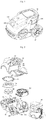
- FIG. 1 is a perspective view illustrating an external appearance of a cleaner according to the present invention
- FIG. 2 is an exploded perspective view illustrating the cleaner.
- FIGs. 1 and 2 Some of the constituents and features of the cleaner illustrated in FIGs. 1 and 2 may be the same as or similar to those from conventional cases. However, constituents and features for retraction and drawing-out of a power cord represent the spirit of the present invention and thus will be described in detail.
- the cleaner according to the present invention may include a suction nozzle (not shown) to move along the floor to be cleaned to suction air containing foreign matters, a cleaner body 100 provided separately from the suction nozzle, and a connection tube (not shown) to interconnect the suction nozzle with the cleaner body 100 and guide suctioned air from the suction nozzle to the cleaner body 100.
- a nozzle suction inlet (not shown) having a predetermined size is formed at the bottom of the suction nozzle to suction foreign matters accumulated on the floor into the cleaner body along with air.
- the front of the cleaner body may be provided with a body suction inlet 162 communicating with the suction nozzle to allow introduction of air into the cleaner body, and a body exhaust outlet (not shown) to discharge the air outside the cleaner body may be provided at one lateral side of the cleaner body.
- a dust collector 200 may be detachably mounted to the rear of the cleaner body 100.
- the dust collector 200 functions to separate foreign matters from the air suctioned through the suction nozzle and collect the same.
- the dust collector 200 may be detachably mounted to the upper portion or the front of the body.
- an electrical unit (not shown) to control the vacuum cleaner and a fan-motor assembly 130 to suction air into the cleaner body and force the air to flow through the cleaner body may be installed in the cleaner body 100.
- the fan-motor assembly 130 may be accommodated in a cylindrical motor chamber 133 having an open top.
- the motor chamber 133 may be installed in a lower case 120 of the cleaner body.
- a motor cover 131 having a motor suction inlet 131a of a predetermined shape to allow the air past through the dust collector to be suctioned thereinto may be installed at the upper portion of the motor chamber 133.
- a motor mounting part 134 to fix the motor cover 131 and fan-motor assembly 130 to the motor chamber 133 may be installed at the upper portion of the motor cover 131.
- the lower case 120 may be provided with a motor chamber installation part (not shown) at which the lower portion of the motor chamber is installed.
- the motor mounting part 134 may be coupled to an upper case 160 forming the upper portion of the cleaner body.
- the upper case 160 is provided with a suction channel (not shown) to guide suctioned external air into the dust collector 200, and a first suction inlet 165 communicating with the dust collector is provided at the end of the suction channel.
- the upper case 160 is provided with an exhaust channel (not shown) to guide the air past through the dust collector 200 into the motor chamber 133.
- One end of the exhaust channel is provided with a first exhaust outlet 163 communicating with the dust collector 200, and the other end of the exhaust channel communicates with the motor suction inlet 131a formed at the motor cover.
- an exhaust chamber 140 to discharge the air past the motor chamber may be provided at a lateral surface of the motor chamber 133.
- An exhaust filter (not shown) may be installed at the exhaust chamber 140 to re-filter out foreign matters contained in the air before the air past the motor chamber is discharge to the outside.
- a HEPA filter to filter out fine dust is used as the exhaust filter (not shown).
- the exhaust filter (not shown) is installed at a filter support member (not shown).
- the filter support member (not shown) is detachably coupled at the inside of the exhaust chamber to facilitate replacement of the exhaust filter (not shown).
- the air past through the filter is discharged outside through a body exhaust outlet (not shown) formed at an exhaust chamber cover 141.
- a cord reel assembly 150 Installed at the rear of the motor chamber is a cord reel assembly 150.
- the cord reel assembly 150 functions to keep a power cord, which is provided to supply electrical power to the cleaner body, wound therearound.
- the central shaft of the cord reel assembly 150 is perpendicular to the ground.
- One side of the cord reel assembly 150 is provided with a lock releaser 151 to control operation of the cord reel 150.
- a lock releaser includes a lock release button 151.
- the other side of the cord reel assembly 150 is provided with an introduction inlet 170 allowing a power cord to be retracted or drawn out therethrough. That is, the introduction inlet 170 may function as a passage allowing the power cord to be retracted or drawn out.
- the introduction inlet 170 may be provided at the body 100.
- the cord reel 150 When the power cord is drawn out through the introduction inlet 170, the cord reel 150 may rotate, for example, clockwise to allow the wound power cord to be drawn out from the body. On the other hand, when the power cord retracts through the introduction inlet, the cord reel 150 may rotate, for example, counterclockwise to allow the power cord to be wound and retracted into the body.
- the central shaft of the cord reel assembly 150 may alternatively be disposed parallel to the ground. That is, the cord reel may be disposed perpendicular to the ground. The disposition of the central shaft may vary depending on the position at which the cord reel 150 is mounted in the body.
- the cord reel assembly 150 may be provided in the cleaner, more specifically, in the cleaner body.
- the cord reel assembly 150 may alternatively be provided at the exterior of the cleaner body. However, it is preferred in view of aesthetics of the external appearance of the cleaner that the cord reel assembly 150 is provided in the cleaner body 100.
- the cord reel assembly 150 is provided to wind a power cord 190 ( FIG. 5 ).
- the power cord is provided to apply electrical power to the cleaner. That is, one side of the power cord may be provided with a power plug, which is not shown, and the other side thereof may be connected to electrical units in the cleaner. Electrical power may be applied to the cleaner when the power plug is connected to a wall outlet.
- the cord reel assembly 150 may include a cord reel 152.
- the cord reel 152 may include cord reel housings 152a and 152b provided respectively at both sides of the cord reel 152.
- the power cord may be wound around the central portion 152c between the cord reel housings 152a and 152b.
- the cord reel housings 152a and 152b of the cord reel 152 may be formed in a circular shape and coupled to each other.
- the cord reel housings 152a and 152b are arranged to rotate about a cord reel central shaft 154.
- the cord reel 152 may rotate clockwise to wind the power cord and rotate counterclockwise to allow the power cord to be drawn out.
- the cord reel assembly 150 may include an elastic device 158. That is, the cord reel assembly 150 may be provided with the elastic device 158 to apply torque.
- the elastic device 158 may engage with the cord reel central shaft 154. Accordingly, the elastic device 158 may be provided at the central portion of the cord reel 152 or near the central portion.
- the elastic device 158 may generate torque to cause the cord reel 152 to rotate clockwise to return.
- the elastic device 158 when the power cord is drawn out by a user, the elastic device 158 generates torque in the opposite direction. That is, as the user pulls the power cord out, the magnitude of elastic resilience or the restitutive rotational force increases. Accordingly, the user needs to apply force large enough to overcome the torque to draw out the power cord.
- the elastic device 158 is a general constituent for the cord reel assembly of the cleaner, and thus a detailed description thereof will be omitted.
- a cord reel locker is provided.
- the locker is generally provided to prevent rotation of the cord reel 152 or the cord reel housings 152a and 152b.
- Such a cord reel locker also uses elastic force.
- the user needs to apply a large force when drawing out the power cord. That is, since the user needs to pull the power cord, overcoming the elastic restoring force of the elastic device 158 and the elastic restoring force of the cord reel locker, the user undergoes much difficulty in drawing out the power cord.
- the present invention may minimize the inconvenience as above.
- the cord reel assembly 150 may include a cord reel case 153 to accommodate the cord reel 152.
- the cord reel case 153 may be provided at both sides of the cord reel 152, or at one side thereof.
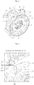
- FIG. 3 illustrates that the cord reel case 153 is provided only at one side.
- the cord reel case 153 may also function to allow the cord reel assembly 150 to be positioned and fixed in the cleaner body. Accordingly, when the cord reel case 153 is provided only at one side of the cord reel 152, the cord reel 152 may be surrounded at the other side of cord reel 152 by structures in the body.
- the cord reel case 153 may be preferably provided at both sides of the cord reel. In this case, manufacturing and handling of the cord reel assembly 150 may be facilitated. Further, connection between the cord reel assembly 150 and the cleaner body 100 may be facilitated
- the cord reel case 153 accommodates the cord reel 152. Therefore, to accommodate the cord reel 152 at the correct position and prevent the same from being displaced from the position, the cord reel central shaft 154 is preferably integrated with the cord reel case 153.
- the power cord 190 is wound around the central portion 152c of the cord reel 152.
- the power cord 190 is wound between the cord reel housings 152a and 152b at both sides of the cord reel 152.
- guide portions 155, 156 and 157 are preferably provided to guide the power cord 190 to the central portion 152c of the cord reel 152.
- the guide portions 155, 156 and 157 may be formed to correspond to the width of the cord reel 152.
- the guide portions 155, 156 and 157 may be formed to correspond to the horizontal width of the cord reel 152.
- the guide portions may be formed to correspond to the vertical width of the cord reel 152.
- the guide portions 155, 156 and 157 may be arranged at the inside of the introduction inlet 170. Parts of the guide portions may alternatively arranged at the outside of the introduction inlet 170. In any case, the power cord may be guided through the guide portions 155, 156 and 157 to enter the body 100.
- the guide portions 155, 156 and 157 may include a cord guide 156 provided at one side of the cord reel 152 to guide movement of the power cord 190.
- the direction in which the power cord enters the body may different from the direction in which the power cord is wound around the cord reel 15.
- the power cord entering the body in a substantially horizontal direction may extend substantially in a vertically downward direction to be wound around the cord reel 152.
- the power cord entering the body in a substantially horizontal direction may extend in a substantially perpendicular lateral direction to be wound around the cord reel 152.
- the cord guide 156 may be arranged to smoothly divert the introduced power cord in the body.
- the power cord 190 may retract, maintaining contact with the cord guide 156.
- the cord guide 156 preferably includes, as shown in FIG. 4 , a level portion 156a and a curved portion 156b.
- the curved portion 156b is preferably formed in the shape of a curved surface to minimize friction.
- the guide portions 155, 156 and 157 may include side guides 155 and 157 provided at the opposite sides of the cord guide 156.
- the side guides may guide lateral sides or vertical sides of the power cord. That is, the portions guided by the side guides may change depending on whether the cord reel assembly 150 is vertically arranged or horizontally arranged.
- the side guides 155 and 157 may also be adapted to serve as a structure to mount the cord locker 180. Further, the side guides 155 and 157 may be integrated with the cord reel case 153 as a portion of the cord reel case 153. Alternatively, the side guides 155 and 157 may be constituents adapted to be coupled to the cord reel case 153. For example, in FIG. 3 , one side guide 155 is integrated with the cord reel case 153, while the other side guide 157 is coupled to the cord reel case 153.
- the other side guide 157 configured as above may be a support bracket. As will be described later, the support bracket may be coupled to the cord reel case 153 to facilitate coupling of the cord locker 180. Specifically, the support bracket may function to facilitate coupling between the lever 180a and the rotational roller 183 and allow operation or movement thereof In other words the support bracket is a constituent to support the cord locker against the cord reel case.
- the cord locker 180 may be provided at the guide portions that guide the power cord introduced into the body to the cord reel. That is, movement of the power cord may be selectively allowed or locked directly by the guide portions.
- the cord locker 180 preferably allows the power cord to be drawn out at any time. Further, the cord locker 180 preferably prevents automatic retraction of the power cord when the cord is drawn out. Accordingly, the cord locker 180 in operation means that retraction of the power cord is prevented. That is, it means that retraction of the power cord is made difficult. In addition, the cord locker 180 selectively allows retraction of the power cord. That is, the retraction of the power cord may be prevented in a locked state, while the power cord may be automatically retracted in a release state. That is, the power cord may be retracted and wound around the cord reel by elastic restoring force.
- the cord locker 180 is preferably arranged to directly hold the power cord. That is, the cord locker 180 may be arranged to prevent movement of the power cord by directly holding the power cord to and allow movement of the power cord by releasing the power cord. Direction prevention of the movement of the power cord result in prevention of rotation of the cord reel.
- the cord locker 180 is preferably arranged such that the power cord is selectively held and released directly by the cord guide. That is, the cord locker 180 is preferably arranged such that the cord guide selectively allows or prevents movement of the power cord. Therefore, the cord locking and releasing mechanism for the power cord may be embodied by the cord guide. More specifically, the mechanism to hold or release the power cord may be embodied on the cord guide 156.
- the cord locker 180 may be arranged to directly hold the power cord in the guide portions 155, 156 and 157. That is, the mechanism may be embodied in the space in the guide portions. Thereby, the cord locker 180 is arranged to directly hold the power cord that is not yet wound around the cord reel. Thereby, inertia may be prevented from obstructing winding of the retracting power cord around the cord reel.
- cord locker 180 will be more specifically described.
- the cord locker 180 selectively performs allowing or preventing the movement of the power cord. Specifically, such a function may be realized through a gap defined between the cord locker 180 and the cord guide 156, as shown in FIG. 4 . That is, the cord locker 180 and the cord guide 156 define a gap g, and the size of the gap g is variable. That is, when the size of the gap increases, movement of the power cord is allowed. When the size of the gap decreases, movement of the power cord may be prevented. Therefore, the cord locker 180 may be arranged such that as the size of the gap varies, movement of the power cord is selectively allowed or locked.
- the cord locker 180 may include a lever 180a adapted to rotate about the central shaft 184. That is, the central shaft 184 and the lever 180a may be arranged to form a structure similar to that of a seesaw. As the lever 180a rotates, the size of the gap g may be varied.
- the lever 180a may include a locking portion 182 and a releasing portion 181 arranged at opposite sides of the central shaft 184.
- the locking portion 182 and the releasing portion 181 may be integrated with each other. Thereby, the gap may be defined between the locking portion 182 and the cord guide 156.
- one end of the lever 180a may be provided with a rotational roller 183 defining the gap g through cooperation with the cord guide 156. That is, the locking portion 182 may include the rotational roller 183, or the rotational roller 183 may be provided at the locking portion 182.
- the rotational roller 183 may be arranged to rotate about the rotation shaft 186.
- the rotational roller 183 may be arranged to rotate to minimize friction with the power cord 190. However, friction needs to be ensured to some extent since it is preferable for the rotational roller to rotate to an extent through friction between the power cord and the rotational roller.
- Rotation of the rotational roller may suggest that the rotational roller may function as a buffer to prevent sudden impact when the power cord starts or stops moving. Therefore, the outer surface of the rotational roller is formed of rubber or silicone to satisfy required properties of buffering and friction.
- the locking portion 182 may be provided, as shown in FIG. 3 , with a roller accommodation portion 185 allowing the rotational roller 183 to be arranged therein. Accordingly, the rotation shaft 186 of the rotational roller may be rotatably arranged in the accommodation portion 185, and the rotational roller 183 may be arranged on the rotation shaft 186.
- the roller accommodation portion 185 may be formed to surround the outer circumferential surface of the rotational roller 183. Alternatively, the roller accommodation portion 185 may be formed to surround only a portion of the outer circumferential surface of the rotational roller 183.
- the power cord When cleaning is proceeded, the power cord may be dragged around on the floor surface, and thereby dust on the floor surface may attach to the power cord. Therefore, the power cord may be easily contaminated, and the dust may be introduced into the cleaner body when the power cord retracts into the cleaner body. This dust may affect performance of the elastic device 158 of the cord reel assembly 150, and further obstruct rotation of the cord reel. Therefore, it is necessary to prevent such contaminants from affecting the cord reel assembly 180.
- the rotational roller 183 is preferably arranged to contact the power cord when rotating such that contaminants attached to the power cord is transferred to the rotational roller 183.
- the contaminants attached to the rotational roller 183 are preferably removed by a recess structure 185a of the roller accommodation portion 185.
- the recess structure 185a may include a structure provided with a plurality of recesses formed in the longitudinal direction of the rotational roller 183. Such a structure may prevent a large contaminant from being stuck between the rotational roller 183 and the accommodation portion 185 and obstruction rotation of the rotational roller 183.
- the recess structure 185a may be formed in the shape of tooth grooves. The tooth grooves may minimize the areas of the rotational roller 183 and the roller accommodation portion 185 facing each other, thereby effectively removing contaminants and preventing the contaminant from being stuck.
- the cord locker 150 may include a central shaft 184 and a rotational roller rotation shaft 186. That is, the cord locker 150 may include at least two constituents to rotate about two centers. Accordingly, it is preferable that one side of the cord locker 150 is constrained by the cord reel case 155 and the other side thereof is constrained by the support bracket 157. By using the support bracket 157, the constituents having at least two centers of rotation may be easily coupled to each other.
- the cord locker 150 may be fixed.
- the cord locker 150 may be fixed such that the cord locker 150 is allowed to perform desired operation. Accordingly, assembly is facilitated.
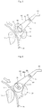
- FIGs. 5 to 7 are conceptual views for clear understanding of a structure for such mechanism. Accordingly, constituents of FIGs. 5 to 7 may be different from those of FIGs. 3 and 4 .
- FIG. 5 shows a state to which the cord locker 180 is set when a user draws out the power cord 190. That is, FIG. 5 shows a state in which the power cord is continuously drawn out.
- the size of the gap g may increase.
- the lever may rotate, for example, clockwise.
- the size of the gap between one end of the lever and the cord guide 156, i.e., the gap g may increase.
- the size of the gap between the rotational roller 183 of the lever and the cord guide 156, i.e., the gap g may increase.
- the rotational roller 183 may rotate in a direction allowing the power cord to be drawn out. The rotation may be caused by friction between the power cord and the rotational roller 183.
- the rotational roller rotation shaft 186 may be arranged to allow translational motion of the rotational roller 183 in addition to rotation of the rotational roller 183. That is, the rotational roller 183 may be allowed to rotate and make translational movement due to friction between the rotational roller 183 and the power cord.
- one end of the lever 180a may be provided with a groove to accommodate the rotation shaft 186 of the rotational roller 183.
- the rotation shaft 186 may rotate and make translational movement in the groove.
- the inner diameter of the groove may be larger than the outer diameter of the rotation shaft 186.
- the groove 187 is preferably formed in the shape of a long hole. That is, the rotation shaft 186 is allowed to make translational movement in the longitudinal direction of the long hole.
- the direction of translational movement may be set such that the size of gap g varies when the rotational roller 183 makes translational movement with rotation of the lever 180a constrained. That is, the long hold may be formed such that the size of the gap g increases or decreases depending on the direction of translational movement.
- the longitudinal direction of the long hole may be set to the tangent direction of the lever 180a or the rotational roller 183. Thereby, smooth rotation and translational movement may be allowed.
- Rotation and translational movement of the roller rotation shaft 186 may have effects as follows.
- An elastic member 188 may be provided at the central shaft 184 of the lever 180a or near the central shaft 184.
- the elastic member 188 resists rotation in a direction in which the size of the gap g increases and produces restoring force in the direction opposite the direction of rotation. That is, as shown in FIG. 5 , when the lever 180a rotates clockwise to increase the size of the gap g, the elastic member 188 produces rotational force to rotate the lever 180a counterclockwise. Therefore, when drawing out the power cord 190, the user needs to overcome not only the elastic force of the cord reel described above but also the elastic force of the elastic member 188. However, translational movement of the rotation shaft 186 described above eliminates the need to overcome at least the elastic force of the elastic member 188.
- the rotational roller 183 and the lever 180a are moved to positions at which the size of the gap g is minimized. That is, they return to initial state.
- the rotation shaft 186 of the rotational roller 183 makes translational movement due to friction between the power cord and rotational roller 183 in the direction allowing the size of the gap to decrease, as shown in FIG. 6 .
- the lever 180a return to the original position thereof, i.e., to the position at which the gap is minimized. Accordingly, when the gap is minimized, the power cord is pressed in the gap and prevented from moving. This state may be referred to as the power cord locked state or locked state.
- the rotational roller 183 may rotate in the direction in which the power cord retracts when the gap is minimized.
- force may be produced to further rotate the lever 180a in the direction in which the gap decreases.
- the lever 180a and the elastic member 188 may be damaged, and secure prevention of retraction of the power cord may fail.
- a locking guide 159 to selectively contact the lever or the rotational roller to limit the maximum angle the lever rotates in the direction in which the size of the gap decreases may be provided. That is, the locking guide 159 may be provided to prevent further rotation of the lever in the locked state.
- the maximum angle is an angle between the position the lever reaches by rotation to maximize the gap and the position at which the lever in the initial state and. Therefore, due to the locking guide 159, the maximum angle may be limited not to increase.
- the locking guide 159 may selectively contact the lever 180a. In addition, the locking guide 159 may contact the rotational roller 183 in the locked state. At this time, the power cord may be held tightly between the rotational roller 183 and the cord guide 156. Accordingly, while the power cord attempts to rotate the rotational roller counterclockwise by retracting, the locking guide 159 prevents such rotation, as shown in FIG. 6 . Thereby, rotation of the rotational roller 183 is prevented in the locked state, and therefore the power cord may be securely maintained in the locked state.
- the rotation shaft 186 in the long hole 187 makes translational movement in the direction that decreases the gap. Accordingly, impact in the locker 180 eases. In other words, since the power cord is slowly held for the sufficient time allowing the power to make translational movement to a certain distance, impact is buffered and thus the durability of the locker 180 or the cord reel assembly 150 may be enhanced. Such buffer effect may be effectively realized not only by translational movement of the rotational roller but also by rotation of the rotational roller.
- the user may release the locker 180 to allow the power cord 190 to retract.
- the locker 180 is released to allow the power cord to be automatically retracted by the elastic device 158 of the cord reel assembly 150, as shown in FIG. 7 .
- the user may cause the lever 180a to rotate in the direction allowing the gap g to increase. Specifically, the lever 180a is allowed to rotate by pressing the releasing portion or the lock release button 181.
- the release button 181 may be pressed directly by the user or by manipulating a mechanism. By such manipulation, the lever 180a may be rotated to increase the gap g sufficiently or to the maximum. This means that force to prevent retraction of the power cord is not produced.
- the power cord may contact the cord guide 156.
- friction caused by such contact is trivial compared to the elastic restoring force of the elastic device 158, and therefore the power cord may easily retract.
- the power cord contact the rotational roller 183.
- the rotational roller 183 may also rotate, and the power cord may easily retract. Accordingly, the cord guide 156 and the rotational roller 183 may function to buffer impacts by the retracting power cord.
- the locker may be reset to the locked state before the power cord is completely retracted. That is, when force pressing the release button 181 is removed, the lever 180a is rotated by the elastic restoring force of the elastic member 184 in the direction allowing the size of the gap to decrease. Thereby, the locker may be reset to the locked state shown in FIG. 6 .
- the power cord retracts very quickly. This quick retraction is allowed by the restoring force of the elastic device 158 substantially maximized in this state. Accordingly, when the locked state is suddenly set while the locked state is released, retraction of the power cord may be abruptly prevented. In this case, large impacts to the cord reel assembly 150 and the locker 180 may occur. For example, in conventional cases, rotation of the cord reel itself is prevented, and therefore the cord reel may be damaged and a large portion of the power cord may enter the body with the cord not wound by inertial force.
- the power cord is directly held for a certain time or over a certain distance, and therefore such impacts may be minimized.
- a certain time and distance are taken for the power cord to completely stop from the moment the power cord begins to contact the locker. Impacts are distributed over this distance and for this time. Therefore, more smooth and gentle locking of the power cord may be realized.
- the length of the power cord that is retracted into the body without being wound around the cord reel may be remarkably reduced.
- the power cord is allowed to be wound around the central portion 152c of the cord reel 152
- the embodiment may be implemented separately from the previous embodiment.
- the present embodiment may be implemented in combination with the previous embodiment.
- the power cord 190 is wound around the cord reel 152.
- Part of the guide portions may be arranged in the introduction inlet 170.
- the direction in which the power cord is introduced into the body may not correspond to the direction in which he introduction inlet 170 or the guide portions are arranged.
- the power cord may extend outside the cleaner body in an inclined direction with respect to the longitudinal direction of the cleaner body. In this case, when the cord locker is released, the power cord may contact one side of the introduction inlet 170 and be wound not round the central portion of the cord reel 152 but around a portion close to one side thereof.
- FIG. 8 shows an example of winding of the power cord around a portion of the cord reel close to one side thereof not around the central portion 152c.
- the entire power cord may not be sufficiently wound around the cord reel. That is, the space for winding of the power cord may be fully filled with a portion of the power cord even before the power cord is sufficiently wound. This occurs as the space of the cord reel case, i.e., a space allowing rotation of the cord reel is filled with the power cord although the elastic device of the cord reel still has elastic restoring force. In other words, insufficient winding may be caused by filling up of the space to accept the power cord introduced thereinto.
- the user may need to force the power cord into the body.
- the power cord forced into the body may be entangled in the body, thereby resulting in difficulty in re-drawing out the power cord from the body.
- the object of the present invention is to solve the problem as above and provide a cleaner convenient to use. That is, a cleaner allowing the retracting power cord to be guided to the central portion of the cord reel and intensely wound around the central portion of the cord reel is provided.
- the present embodiment is intended to provide a cleaner which prevents winding of the power cord around a portion of the cord reel close to one side thereof and allow the cord reel to be intensely wound around the central portion 152c.
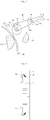
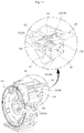
- FIGs. 9 and 10 show an example of the direction guide assembly 300 according to the illustrated embodiment.
- the direction guide assembly functions to direct the power cord 190 introduced into the cleaner toward the central portion of the cord reel assembly 150 (see FIG. 3 ). That is, the direction guide assembly functions to prevent leaning of the power cord 190 to one side and allow the power cord 190 to be introduced toward the central portion of cord reel assembly.
- the direction guide assembly 300 may be arranged in an introduction inlet 170 provided in the cleaner body 100. Only a portion of a direction guide assembly 300 may be provided in the introduction inlet 170, as shown in FIG. 10 .
- the direction guide assembly 300 may be provided at one side of the cord reel assembly 150. That is, the power cord sequentially passes through the introduction inlet 170 and the direction guide assembly 300 or passes through the direction guide assembly 300 to be wound around the cord reel assembly 150.
- the direction guide assembly 300 may include a cord guide 310.
- the cord guide 310 is a constituent to divert the introduction direction of the power cord 190 toward the cord reel 152. Accordingly, the cord guide 310 may be the same as the cord guide 156 shown in FIG. 3 . Therefore, the cord guide 310 guides the directions of introduction and winding of the power cord such that the power cord may be smoothly wound around the cord reel 152.
- the cord guide 310 may guide the direction in which the power cord is introduced into the body. Further, the cord guide 310 may guide the direction in which the power cord extends to the cord reel assembly in the body. In other words, the cord guide 310 may guide the direction in which the power cord extends from the outside of the body to the cord reel assembly.
- the cord guide 310 may be positioned horizontally as shown in FIG. 10 or vertically. The position of the cord guide 310 may depends on whether the cord reel assembly is positioned horizontally or vertically as described above.
- the direction guide assembly 300 may include direction guides 322 and 332 to divert the power cord introduced into the cleaner to the central portion of the cord reel assembly. That is, the direction guides 322 and 332 may prevent the power cord from leaning to the left, right, up, or down side when the power cord retracts. In addition, the direction guides 322 and 332 may direct the power cord toward the central portion of the cord guides or the cord reel assembly even when the power cord leaning to one side is introduced into the cleaner.
- the direction guides 322 and 332 may be respectively provided at opposite sides of the cord guide 310.
- the direction guides 322 and 332 are arranged such that the horizontal or vertical width therebetween allowing the power cord to be introduced narrows along the direction in which the power cord is introduced. That is, the direction guides 322 and 332 may be arranged such that the width of the inside of the introduction inlet 170 narrows gradually along the direction in which the power cord is introduced.
- the inside of the introduction inlet 170 may be formed in a trapezoid shape such the width thereof narrows long the direction in which the power cord is introduced through the direction guides 322 and 332. Accordingly, the power cord leaning to one side may be guided to the central portion through the direction guides.
- FIG. 9 shows the direction guides 322 and 332 respectively provided at opposite sides of the cord guide 310.
- only one direction guide configured as above may be provided. It may be possible to narrow the lateral width along the introduction direction with one direction guide.
- the direction guides are preferably provided at the opposite sides of the cord guide since impact due to introduction of the power cord does not occur only at one lateral surface as will be described later.
- the direction guides 322 and 332 may be obliquely arranged.
- the power cord introduced leaning to one side is guided to the center along the direction guide and wound around the cord reel assembly.
- each of the direction guides is preferably elastically supported.
- One direction guide 322 may include a rotation center portion 321 and a guide member 323 extending from the rotation center portion 321 into the body to narrow the space through which the power cord is introduced.
- the rotation center portion 321 is preferably arranged adjacent to the introduction inlet of the body.
- the rotation center portion 321 may form the last point from which the power cord is drawn out of the body. For this reason, the power cord may directly contact the rotation center portion 321.
- the exterior of the rotation center portion is preferably formed in a cylindrical shape. This shape may reduce friction between the rotation center portion and the power cord since this shape allows the power cord to smoothly slide along the circumferential surface of the rotation center portion.
- the rotation center portion 321 is rotatably supported by one sidewall 320.
- the other rotation center portion 331 is rotatably supported by the other sidewall 330.
- the rotation center portion 321 may be viewed as being formed at one side of the guide member 323.
- An elastic member 324 may be provided between the other side of the guide member 323 and the one sidewall 320.
- an elastic member 334 may be provided between the other side of the other guide member 333 and the other sidewall 330. Accordingly, the distance between the other side of the guide member 323 and the one sidewall 320 may vary while one side of the guide member 323 rotatably fixed to the one sidewall 320. Such variation of the distance is allowed by the elastic member 334 and may remarkably reduce impact caused by introduction of the power cord.
- the guide members 323 and 333 may rotate respectively about the rotation center portions 321 and 331 to some extent. As the guide members rotate, the width of the space through which the power cord is introduced is allowed to vary, and therefore sudden change in direction of introduction of the power cord may be prevented.
- the power cord introduced through the central portion of the cord guide 310 from the first is not affected by the direction guide 322 when wound around the cord reel.
- the power cord may be introduced leaning to one side.
- the power cord may be introduced leaning to the left. This situation may occur when the cord locker is released in a state in which the power cord is extended to the right side of the introduction inlet 170. When the cord locker is released, the power cord moves from the right to the left toward the introduction inlet 170. The direction of movement of the power cord near the introduction inlet 170 suddenly changes toward the introduction inlet 190. Therefore, the power cord retracting according to inertia hits the left guide member 333.
- the power cord contacts the guide member 333 provided on the left side thereof to rotate the guide member counterclockwise, as shown in FIG. 9 .
- the elastic member 334 is elastically deformed to produce restoring force, and then gradually return to the original position thereof. Thereby, the power cord may be moved to the central portion of the cord guide 310 and introduced.
- the elastic support by the guide member functions to buffer impact between the retracting power cord and the guide member. Further, by gradually changing the position through which the power cord retracts, occurrence of a sudden impact may be prevented.
- the power cord may caused to be gradually wound around the central portion of the cord reel.
- the overall power cord may be allowed to be sufficiently wound round the cord reel.
- the impact between the power cord and the introduction inlet 170 may be buffered during retraction of the power cord, allowing the power to be wound around the central portion of the cord reel.
- the two embodiments may be independently implemented. That is, the direction guide assembly 300 shown in FIG. 11 may be omitted or the cord locker 180 may be omitted. Accordingly, description of the same constituents will be omitted.
- the retracting power cord 190 is introduced into the body along the cord guides 156 and 310.
- the power cord 190 is moved to the center of the cord guide along the direction guide or the guide members 323 and 333 while being wound around the cord reel assembly 150.
- the cord guides 156 and 310 may be formed to sufficiently extend into the body. Accordingly, the rotational roller 183 may be positioned at the rear side of the guide member to define a gap in cooperation with the cord guide.
- the rotational roller 183 may be positioned between the guide members 323 and 333. In this case, the width of the rotational roller may be narrowed. However, when the guide member is rotated, the power cord may be stuck between the guide member and the lateral surface of the rotational roller. Therefore, the rotational roller 183 is preferably provided at the rear side of the guide member. That is, the rotational roller 183 is preferably positioned to selectively lock the power cord moved to the center through the guide members.
- the position of the rotational roller 183 is not limited thereto.
- the rotational roller 183 may alternatively be provided at the front side of the guide member. In this case, retraction of the power cord may be selectively implemented at the front of the guide member through the locker 180.
- the guide members 323 and 333 are rotatably arranged at the sidewalls 320 and 330 or the side guides 155 and 157. Thereby, it is preferably to facilitate assembly of such guide members.
- a guide fixing portion 350 connected to the respective rotation center shafts 321 and 331 of the guide members to fix the direction guide or the guide members is preferably provided. That is, the guide fixing portion 350 may be positioned at the upper portions of the rotation center shafts 321 and 331 on both sides to facilitate fixation of the guide members.
- a predetermined gap is formed between the guide fixing portion 350 and the cord guide 156, 310 to form a space through which the power cord retracts.
- the cord guide is preferably formed to have a circular cross section to minimize friction with the power cord. That is, the guide fixing portion may be formed in a cylindrical shape to reduce the area of contact with the retracting power cord.
- the guide fixing portion may be omitted since the power cord first passes through the gap between the rotational roller 183 and the cord guide 156 when retracting into the body.
- the cord locker 180 is arranged near the introduction inlet 170 of the body or the cord guide 156, 310 along which the power cord retracts.
- the position of the cord locker 180 is adjacent to a portion along which the power cord retracts into the body 100.
- the release button 181 of the cord locker 180 is positioned near the introduction inlet 170. This allows the user to clearly identify the position and function of the release button 181, and thereby the release button may be very convenient to use.
- the release button 181 and the introduction inlet 170 are provided at the opposite sides of the body 100. Accordingly, the user may not clearly identify the use or position of the release button 181.
- the user is allowed to clearly identify the position and use of the release button 181. That is, the user may intuitively identify the position of the release button 181 and the use or function of the release button 181.
- the cord guide 156 and the locker 180 are arranged at the opposite positions. In any case, retraction of the power cord may be selectively allowed or released through variation of the gap between the cord locker 180 and the cord guide 156.
- a cord locker and a direction guide assembly may be realized independently or together.
- the cleaner shown in the drawings is of a canister type, but it is also applicable to an upright type cleaner. This is because the above embodiments may be irrelevant to the shape of the body, the suction nozzle and the connection between the body and the suction nozzle.
- the cleaner becomes convenient to use by allowing a power cord to be wound around a central portion of a cord reel assembly power cord and thereby sufficiently wound.
- the cleaner may prevent sudden introduction or drawing out of the power cord by smoothly changing the direction of movement of the power cord introduced or draw out by using a cord guide.
- the cleaner may have an enhanced durability by preventing damage to a portion of a cleaner body through which the power cord is introduced into the body.
- the cleaner may be have an enhanced durability and reliability for a cord reel assembly.
- the cleaner may allow a user to conveniently use a cord locker.
- the cleaner may allow the power cord to be directly held to prevent automatic introduction of the power cord to thereby prevent malfunction of the cord reel assembly and entanglement of the power cord and ensure easy repetitive use of the cord locker.
- the cleaner may effectively prevent user misrecognition of the position and use of a lock release button for releasing a cord locker.
- the cleaner may prevent occurrence of an impact caused by sudden stop of the power cord by ensuring sufficient time and distance needed to stop movement the power cord.
Landscapes
- Engineering & Computer Science (AREA)
- Mechanical Engineering (AREA)
- Electric Vacuum Cleaner (AREA)
Description
- The present invention relates to a vacuum cleaner, and more particularly, to a vacuum cleaner having an improved structure for pulling in and withdrawing a power cord, thereby providing user convenience and enhancing durability.
- In addition, the present invention relates to a vacuum cleaner preventing a power cord from tangling when the power cord is retracted, thereby enhancing reliability.
- In general, the vacuum cleaner is a device suctioning foreign materials along with air and filtering them out in the body of the vacuum cleaner. The vacuum cleaner generally includes a body having a motor installed therein to generate suction force, a suction nozzle to suction foreign matters and air from the floor surface, and a dust collector to filter out foreign matters.
- In the present specification, the vacuum cleaner will be simply referred to as cleaner for convenience of description.
- In many cases, the cleaner drives the motor using an external power applied thereto, and is therefore provided with a power cord to which the external power is connect. There is also a vacuum cleaner having a self-charging battery. However, cleaners with a power cord are widely distributed since they are capable of continuously generating sufficient suction force through sable supply of electrical power.
- For a house or building having a wide space, cleaning may be needed for a very large area. Accordingly, the cleaner may need to move a very long distance from a wall outlet. In addition, during cleaning operation, it is tiresome to frequently plug in the power cord to wall outlets positioned at different places. As a result, the power cord is elongated to have a very long length. Exposing such a power cord to the outside of the body after completion of cleaning may result in difficult handling and storing of the cleaner and degradation in aesthetics of the external appearance of the cleaner.
- For the reasons as above, cleansers having a cord reel allowing the power cord to be stored in the cleaner body have been widely distributed. The cord reel, which is used to keep the power cord in a wound state, is a device to automatically wind the power cord using elastic force.
- A user may withdraw the power cord from the cleaner body to perform cleaning and allow the power cord to be automatically retracted into the body by releasing the lock of the cord reel when operation with the cleaner is completed. That is, when locking by the cord reel locker is released, the power cord may be automatically retracted into the body. Accordingly, the user does not need to manually re-place or re-wind the drawn out power cord in the body.
- However, a conventional structure for withdrawal and pulling-in of a power cord has many problems.
- It is preferable that the power cord is closely wound around the middle portion of the cord reel. However, when the power cord is automatically retracted, the power cord may often be wound not around the middle portion of the cord reel, but around portions near the sides of the cord reel. In this case, the power cord may be entangled on the cord reel. That is, the power cord is not sequentially wound. Thereby, the entire power cord may not be sufficiently wound. This results from a portion of the power cord filling the whole space for the power cord and thus blocking rotation of the cord reel even when the power cord is not completely wound.
- Once this problem occurs, the user needs to make arduous efforts to repeat pulling and releasing of the power cord several times to disentangle the power cord. Moreover, the power cord that is not completely retracted automatically results in inconvenience to the user by causing the user to push the unwound portion of the power cord back into the cleaner body.
- Moreover, when the power cord is quickly polled into the cleaner body, it hits the cord introduction inlet, and thereby may cause damage to the cord introduction inlet. That is, the cord introduction inlet may be damaged if the cord reel locker is released after completion of cleaning with the cord introduction inlet misaligned with the power cord. For this reason, it is highly possible that the power cord is wound not at the middle portion of the cord reel, but at a portion biased to one side of the cord reel.
- The cord reel locker functions to prevent the power cord from being automatically retracted after the power cord is pulled out and released by the user. In conventional cases, a cord reel locker blocks rotation of the cord reel, not the movement of the power cord. That is, for the conventional cord reel locker, a user needs to overcome the elastic force of the cord reel locker and the elastic force of the cord reel to withdraw the power cord. In addition, once the withdrawal of the power cord is stopped, rotation of the cord reel is prevented by the elastic recovery of the cord reel locker. Thereby, the power cord is set in the drawn out state.
- Meanwhile, the user may release the cord reel locker to allow the power cord to be retracted. In this case, the cord reel elastically rotates to wind the power cord around the cord reel to cause the power cord to be automatically retractedto the body.
- Therefore, for a conventional cleaner, it may be possible for a user to use excessive force to withdraw the power cord. This is because the user needs to overcome the elastic force of the cord reel and further overcome elastic force of the locker to release the locker when the user withdraws the power cord.
- Moreover, a conventional structure has a following problem.
- For example, when the power cord is drawn out to the maximum length thereof, a user may release the locker to allow the power cord to be retracted. However, the user may apply the locker when power cord is not completely retracted. That is, the user may terminate the pressed state of the lock release button of the locker before the power cord is completely retracted.
- At this time, a large portion of the power cord may fail to be wound around the cord reel due to the inertial force of the power cord retracting into the body of the cleaner. This is because rotation of the cord reel is prevented directly by the locker, while the power cord is retracted into the body by inertial force. This means that a majority of the power cord may be retracted into the body without being directly wound around the cord reel. For this reason, the power cord may be very loosely wound around the cord reel or be entangled in the body.
- When the locker is released again due to this trouble, a majority of the power cord may fail to automatically retract, and thereby the user may need to laboriously force the power cord into the body. In addition, a large force may need to be applied when the entangled cord reel is drawn out.
- Moreover, in the case that rotation of the cord reel is blocked before the power cord retracting at high speed is completely drawn in, the inertia of the retracting power cord may cause the power cord to hit and damage the inside of the body.
-
KR 100354605 B1 - Accordingly, the present invention is directed to a cleaner that substantially obviates one or more problems due to limitations and disadvantages of the related art.
- An object of the present invention is to provide a cleaner having enhanced durability and reliability regarding a structure for drawing out and retracting of a power cord.
- Another object of the present invention is to provide a cleaner which ensures sufficient winding of the power cord by allowing a power cord to be wound around the central portion of a cord reel assembly and is thus convenient to use.
- Another object of the present invention is to provide a cleaner securing an improved durability by preventing damage to a portion of a cleaner body through which a power cord is introduced into the cleaner body.
- Another object of the present invention is to provide a cleaner which may reduce impact between a power cord and the cleaner which occurs when the power cord is retracted.
- Another object of the present invention is to provide a cleaner allowing a user to conveniently use a cord locker.
- Another object of the present invention is to provide a cleaner in which a power cord is directly held to block automatic retraction of the power cord to thereby prevent malfunction of a cord reel assembly and entanglement of the power cord and facilitate repetitive use of a cord locker.
- Another object of the present invention is to provide a cleaner which ensures sufficient time and distance needed to stop movement of a power cord, thereby preventing occurrence of impact due to sudden stop of the power cord.
- Another object of the present invention is to provide a cleaner that may effectively prevent user misrecognition of the position and use of a lock release button for releasing a cord locker.
- Additional advantages, objects, and features of the invention will be set forth in part in the description which follows and in part will become apparent to those having ordinary skill in the art upon examination of the following or may be learned from practice of the invention. The objectives and other advantages of the invention may be realized and attained by the structure particularly pointed out in the written description and claims hereof as well as the appended drawings.
- To achieve these objects and other advantages, the present invention is characterized by the features of claim 1. A cleaner according to the present invention includes a cleaner body, a power cord provided for application of electric power to the cleaner, a cord reel assembly including a cord reel adapted to wind the power cord in the body, and a direction guide assembly formed to have a width narrowing in a direction of introduction of the power cord into the cleaner such that the power cord is directed toward a central portion of the cord reel assembly.
- The cleaner body may be provided with an introduction inlet allowing the power cord to be introduced into or drawn out of the body therethrough, and all or a portion of the direction guide assembly may be arranged in the introduction inlet.
- A sidewall defining a width (a horizontal width or vertical width) for introduction of the power cord may be provided in the introduction inlet. The sidewall may be formed by the cord reel assembly. For example, the sidewall may be provided through a cord reel housing surrounding the cord reel.
- The sidewalls may be formed at opposite sides. One of the sidewalls may be integrated with the cord reel housing, and the other of the sidewalls may be formed through a bracket coupled to the housing.
- Preferably, the direction guide assembly is arranged to individually or independently narrow the width for introduction of the power cord with respect to the sidewalls.
- Preferably, the direction guide assembly includes a cord guide to guide a direction of introduction of the power cord and a direction in which the power cord extends toward the cord reel to be wound around the cord reel, by diverting the power cord from the direction of introduction of the power cord to the direction toward the cord reel.
- As the cord guide is allowed to change the direction of movement of the power cord, the power cord may be more stably wound around the cord reel. This is possible since the power cord is movable by sliding at the cord guide. That is, by applying a predetermined tensional force to the power cord introduced or drawn out, the power cord may be more stably introduced or drawn out.
- For example, the direction of introduction of the power cord may be the same as the direction toward the cord reel. In this case, the rate of introduction of the power cord may be higher than the rate at which the cord reel winds the power cord. As a result, the power cord may be closely wound around the cord reel. However, the rate of introduction of the power cord may be reduced by making the direction of introduction of the power cord different from the direction toward the cord reel through the cord guide, and thereby a predetermined tensional force may be applied to the power cord. Accordingly, the power cord may be closely wound around the cord reel.
- According to the present invention, the direction guide assembly includes a direction guide provided at one side or both sides of the cord guide such that a width for introduction of the power cord gradually narrows toward a center thereof.
- The cord reel assembly may be mounted vertically or horizontally to an inside of the body, and the position of the direction guide assembly may vary depending on the mounting position.
- When the cord reel assembly is vertically mounted, the cord guide may guide the power cord such that the power cord is substantially horizontally introduced into the body and then moved vertically downward. That is, the direction of movement of the power cord may change as the power cord slides on the cord guide. Accordingly, when the power cord is wound around the cord reel, the cord reel may produce tensional force to pull the power cord downward. In addition, the direction guide may be formed at the left and right sides of the cord guide.
- When the cord reel assembly is horizontally mounted, the cord guide may guide the power cord such that the power cord is substantially introduced and then moved to vertical one side (to the left side or the right side). Therefore, when the power cord is wound around the cord reel, the cord reel may produce tensional force to pull the power cord to one side. In addition, the direction guide may be formed at the upper and lower portions of the cord guide.
- According to the present invention, the direction guide is elastically supported to allow the width for introduction of the power cord to be widened by an external force and to be narrowed when the external force is removed.
- The direction guide may include a rotation center portion rotatably arranged at a sidewall extending into an inside of the introduction inlet, and a guide member extending from the rotation center portion into the body such that the width for introduction of the power cord is narrowed.
- Preferably, the guide member is elastically supported to be rotatable with respect to the rotation center portion and to be returned to an original position thereof by an elastic force produced by rotation of the guide member. That is, the guide member preferably returns to the original position at which the width is narrowed. Through such elasticity, an impact produced between the guide member and the power cord may be buffered.
- Preferably, an elastic member is provided between the sidewall and the guide member to elastically support the guide member.
- Preferably, the rotation center portion and the guide member are arranged at opposite sides, and the cleaner is provided with a guide fixing portion connected to the rotation center portion to fix the direction guide.
- Preferably, the guide fixing portion is formed in a cylindrical shape to reduce an area of contact with the power cord introduced into the body.
- The cleaner may further include a cord locker adapted to selectively allow or lock movement of the power cord.
- The cord locker may define a gap in cooperation with the cord guide, and may be adapted to selectively allow or lock movement of the power cord as a size of the gap varies. That is, movement of the power cord may be allowed when the size of the gap increases and may be prevented when the size of the gap decreases. The gap may be increased by an external force exerted by a user. When the external force is removed, a position (an original position) at which the gap is narrowed is preferably recovered.
- The cord locker may include a lever adapted to rotate about a central axis and elastically supported, and a rotational roller provided at one end of the lever to define the gap in cooperation with the cord guide.
- When the power cord is drawn out, a rotation shaft of the rotational roller may make translational movement while the lever is not rotated, to increase the size of the gap. At this time, the rotational roller may make translational movement through the external force produced when the user hold and draws out the power cord. Accordingly, the gap is increased by the external force exerted by the user. When the external force is eliminated, the rotational roller may be returned, by gravity or friction with the power cord, to the position (the original position) at which the gap is narrowed.
- The user may rotate the lever elastically supported by exerting an external force. For example, by pressing a release button, the lever may be rotated. The rotational roller rotates about the central shaft due to such an external force. Through the rotation, the gap between the rotational roller and the cord guide may increase. In this case, the power cord may be automatically introduced by elastic force of the cord reel. In addition, when application of the external force is released, the lever is returned to the original position by the elastic force, and therefore automatic introduction of the power cord may be prevented as the gap decreases.
- Preferably, the cord locker is arranged such that the cord guide selectively holds or releases the power cord to selectively allow or prevent movement of the power cord.
- In another aspect of the present invention, there is provided a cleaner including a cleaner body, a power cord provided for application of electric power, an introduction inlet provided to the body to allow the power cord to be introduced into or drawn out of the body therethrough, a cord reel assembly adapted to wind the power cord in the body, a cord guide to guide a direction in which the power cord is introduced into the body and a direction in which the power cord extends toward the cord reel in the body, and a direction guide formed in a trapezoid shape to have a width narrowing as the direction guide extends into the introduction inlet to direct the power cord introduced into the cleaner toward a central portion of the cord reel assembly.
- Preferably, the cord guide guides the power cord in the body to change a direction of introduction of the power cord or a direction of drawing out of the power cord. That is, the cord guide preferably guides the power cord such that the power cord is substantially horizontally introduced into or drawn out of the body. In addition, the cord guide preferably guides the power cord toward the cord reel assembly.
- Preferably, the power cord horizontally introduced into the body through the cord guide is perpendicularly bent to extend to the cord reel assembly when the power cord leaves the cord guide. Accordingly, the cord guide may be viewed as a constituent to guide the power cord by diverting the power cord introduced or drawn out. Through the cord guide, stabler introduction or drawing out of the power cord may be implemented.
- The direction guide may be provided at each of opposite sides of the cord guide.
- Preferably, the direction guide is rotatable with respect to one side thereof in a direction increasing the width, and is elastically supported to return when rotated.
- The cleaner may further include a cord locker to define a gap between the cord locker and the cord guide and to selectively allow or limit introduction of the power cord by varying a size of the gap. Through the cord guide, the direction of movement of the power cord may be smoothly changed. That is, a predetermined tensional force may be applied to the power cord, and thereby a rate of introduction of the power may be reduced. Accordingly, by forming a variable gap between the cord locker and the cord guide, locking and releasing of the power cord may be more stably implemented.
- In another aspect of the present invention, there is provided a cleaner including a power cord provided for application of electric power, a cord reel assembly adapted to wind the power cord in the cleaner, a cord guide provided at one side of the cord reel to guide movement of the power cord, and a cord locker defining a gap in cooperation with the cord guide and adapted to selectively allow or lock movement of the power cord as a size of the gap varies.
- The cord locker may include a lever to vary the size of the gap by rotating around a central axis. The movement of the power cord is allowed when the size of the gap is large and is prevented when the size of the gap is small since the power cord is pressed in the gap.
- One end of the lever may be provided with a rotational roller to define the gap in cooperation with the cord guide. Due to the rotational roller, the area of direct contact with the power cord may be reduced.
- The cleaner may include a locking guide to selectively contact the lever or the rotational roller to limit the maximum angle the lever rotates in the direction in which the size of the gap decreases. Through the locking guide, the contact area of the rotational roller may be increased, and thereby a locked state may be more securely maintained. That is, the power cord may be prevented from being introduced into the body by rotation of the rotational roller in the locked state.
- One end of the lever may be provided with a groove to accommodate a rotation shaft of the rotational roller. Preferably, the rotation shaft makes translational movement in the groove. Preferably, the size of the gap is varied by the translational movement of the rotation shaft while rotation of the lever is limited. In other words, the translational movement refers to a movement causing the distance between the rotational roller and the cord guide to vary.
- The inner diameter of the groove may be larger than the outer diameter of the rotation shaft. The groove may be formed in the shape of a long hole. Due to the shape of the long hole, the direction of the translational movement may be set to be a specific direction.
- Preferably, a longitudinal direction of the long hole is a direction of a tangent of the lever or the rotational roller.
- The other end of the lever may be provided with a lock release button to release locking of movement of the power cord.
- The lever is provided with a roller accommodation portion to surround an outer circumferential surface of the rotational roller. The roller accommodation portion may be provided with a plurality of tooth grooves or recesses extending in a longitudinal direction of the roller and arranged along a direction of rotation of the roller.
- The cord locker may include an elastic member to apply rotational force in a direction in which the size of the gap decreased.
- The cord reel assembly may include a cord reel allowing the power cord to be wound therearound, and a cord reel case provided at one side of the cord reel to accommodate the cord reel.
- The cord guide and the central shaft may be integrated with the cord reel case. Alternatively, the cord guide may be separately provided and coupled to the cord reel case.
- The cord locker may include a support bracket coupled to the cord reel case to rotatably support the lever. The support bracket may be another cord reel case coupled to the cord reel case.
- The cleaner may include a direction guide assembly to move a position of the power cord introduced from opposite sides of the cord guide to a center of the cord guide.
- The direction guide assembly may include an elastic member provided at a central shaft and at a position spaced apart from the central shaft to buffer impact on the direction guide.
- The direction guide assembly may include direction guides provided at opposite sides of the cord guide, and formed to have a width therebetween narrowing as the direction guides extend inward
- In another aspect of the present invention, there is provided a cleaner including a power cord provided for application of electric power, a cord reel assembly adapted to wind the power cord in the cleaner, a cord guide provided at one side of the cord reel to guide movement of the power cord, and a cord locker including a lever adapted to rotate about a central axis and elastically supported and a rotational roller provided at one end of the lever to define a gap in cooperation with the cord guide, wherein, when the power cord is drawn out, a rotation shaft of the rotational roller makes translational movement while the lever is not rotated, to increase the size of the gap.
- The other end of the lever may be provided with a lock release button to rotate the lever in a direction in which a size of the gap increases to release locking of movement of the power cord. Preferably, the lock release button may be arranged near a introduction inlet through which the power cord is introduced into the cleaner. Accordingly, misrecognition of the position and use of the lock release button by a user may be prevented.
- In another aspect of the present invention, there is provided a cleaner including a power cord provided for application of electric power, a cord reel assembly adapted to wind the power cord in the cleaner, a cord guide provided at one side of the cord reel to guide movement of the power cord, and a cord locker arranged in the cord guide to selectively hold or release the power cord to selectively allow or prevent movement of the power cord.
- The cleaner may include a direction guide provided at both sides of the cor guide to direct the power cord introduced into the cleaner toward a central portion of the cord guide.
- It is possible that the features of the embodiments described above are implemented in combination with each other unless they are mutually contradictory or exclusive.
- It is to be understood that both the foregoing general description and the following detailed description of the present invention are exemplary and explanatory and are intended to provide further explanation of the invention as claimed.
- The accompanying drawings, which are included to provide a further understanding of the invention and are incorporated in and constitute a part of this application, illustrate embodiment(s) of the invention and together with the description serve to explain the principle of the invention. In the drawings:
-
FIG. 1 is a perspective view illustrating an exemplary cleaner applicable to embodiments according to the present invention; -
FIG. 2 is an exploded perspective view illustrating the cleaner shown inFIG. 1 ; -
FIG. 3 is a perspective view illustrating a cord reel assembly according to the present invention; -
FIG. 4 is a longitudinal sectional view illustrating the cord reel assembly shown inFIG. 3 ; -
FIG. 5 is a view schematically illustrating mechanism of a cord locker in drawing-out of a power cord according to the present invention; -
FIG. 6 is a view schematically illustrating mechanism of the cord locker in a locked state according to the present invention; -
FIG. 7 is a view schematically illustrating mechanism of the cord locker in releasing the locked state according to the present invention; -
FIG. 8 is a cross-sectional view illustrating a cord reel applicable to embodiments of the present invention; -
FIG. 9 is a perspective view illustrating a direction guide assembly according to the present invention; -
FIG. 10 is a perspective view illustrating the direction guide assembly ofFIG. 9 mounted to a cleaner body; and -
FIG. 11 is a perspective view illustrating a combination of embodiments shown inFIGS. 3 and9 . - Reference will now be made in detail to the preferred embodiments of the present invention, examples of which are illustrated in the accompanying drawings. Wherever possible, the same reference numbers will be used throughout the drawings to refer to the same or like parts.
-
FIG. 1 is a perspective view illustrating an external appearance of a cleaner according to the present invention, andFIG. 2 is an exploded perspective view illustrating the cleaner. - Some of the constituents and features of the cleaner illustrated in
FIGs. 1 and 2 may be the same as or similar to those from conventional cases. However, constituents and features for retraction and drawing-out of a power cord represent the spirit of the present invention and thus will be described in detail. - As shown in
FIGs. 1 and 2 , the cleaner according to the present invention may include a suction nozzle (not shown) to move along the floor to be cleaned to suction air containing foreign matters, acleaner body 100 provided separately from the suction nozzle, and a connection tube (not shown) to interconnect the suction nozzle with thecleaner body 100 and guide suctioned air from the suction nozzle to thecleaner body 100. - Here, a nozzle suction inlet (not shown) having a predetermined size is formed at the bottom of the suction nozzle to suction foreign matters accumulated on the floor into the cleaner body along with air.
- The front of the cleaner body may be provided with a
body suction inlet 162 communicating with the suction nozzle to allow introduction of air into the cleaner body, and a body exhaust outlet (not shown) to discharge the air outside the cleaner body may be provided at one lateral side of the cleaner body. - In addition, a
dust collector 200 may be detachably mounted to the rear of thecleaner body 100. Thedust collector 200 functions to separate foreign matters from the air suctioned through the suction nozzle and collect the same. Alternatively, thedust collector 200 may be detachably mounted to the upper portion or the front of the body. - Further, an electrical unit (not shown) to control the vacuum cleaner and a fan-
motor assembly 130 to suction air into the cleaner body and force the air to flow through the cleaner body may be installed in thecleaner body 100. - The fan-
motor assembly 130 may be accommodated in acylindrical motor chamber 133 having an open top. Themotor chamber 133 may be installed in alower case 120 of the cleaner body. - More specifically, a motor cover 131 having a
motor suction inlet 131a of a predetermined shape to allow the air past through the dust collector to be suctioned thereinto may be installed at the upper portion of themotor chamber 133. In addition, amotor mounting part 134 to fix the motor cover 131 and fan-motor assembly 130 to themotor chamber 133 may be installed at the upper portion of the motor cover 131. Thelower case 120 may be provided with a motor chamber installation part (not shown) at which the lower portion of the motor chamber is installed. - The
motor mounting part 134 may be coupled to an upper case 160 forming the upper portion of the cleaner body. The upper case 160 is provided with a suction channel (not shown) to guide suctioned external air into thedust collector 200, and afirst suction inlet 165 communicating with the dust collector is provided at the end of the suction channel. - In addition, the upper case 160 is provided with an exhaust channel (not shown) to guide the air past through the
dust collector 200 into themotor chamber 133. One end of the exhaust channel is provided with afirst exhaust outlet 163 communicating with thedust collector 200, and the other end of the exhaust channel communicates with themotor suction inlet 131a formed at the motor cover. - Meanwhile, an
exhaust chamber 140 to discharge the air past the motor chamber may be provided at a lateral surface of themotor chamber 133. An exhaust filter (not shown) may be installed at theexhaust chamber 140 to re-filter out foreign matters contained in the air before the air past the motor chamber is discharge to the outside. - Preferably, a HEPA filter to filter out fine dust is used as the exhaust filter (not shown). The exhaust filter (not shown) is installed at a filter support member (not shown). The filter support member (not shown) is detachably coupled at the inside of the exhaust chamber to facilitate replacement of the exhaust filter (not shown). The air past through the filter is discharged outside through a body exhaust outlet (not shown) formed at an
exhaust chamber cover 141. - Installed at the rear of the motor chamber is a
cord reel assembly 150. Thecord reel assembly 150 functions to keep a power cord, which is provided to supply electrical power to the cleaner body, wound therearound. In addition, the central shaft of thecord reel assembly 150 is perpendicular to the ground. One side of thecord reel assembly 150 is provided with alock releaser 151 to control operation of thecord reel 150. Such a lock releaser includes alock release button 151. - The other side of the
cord reel assembly 150 is provided with anintroduction inlet 170 allowing a power cord to be retracted or drawn out therethrough. That is, theintroduction inlet 170 may function as a passage allowing the power cord to be retracted or drawn out. Theintroduction inlet 170 may be provided at thebody 100. - When the power cord is drawn out through the
introduction inlet 170, thecord reel 150 may rotate, for example, clockwise to allow the wound power cord to be drawn out from the body. On the other hand, when the power cord retracts through the introduction inlet, thecord reel 150 may rotate, for example, counterclockwise to allow the power cord to be wound and retracted into the body. - In contrast with the embodiment shown in
FIG. 2 , the central shaft of thecord reel assembly 150 may alternatively be disposed parallel to the ground. That is, the cord reel may be disposed perpendicular to the ground. The disposition of the central shaft may vary depending on the position at which thecord reel 150 is mounted in the body. - Hereinafter, the cleaner and the cord reel assembly according to the present invention will be described in detail with reference to
FIGs. 3 and 4 . - The
cord reel assembly 150 may be provided in the cleaner, more specifically, in the cleaner body. Thecord reel assembly 150 may alternatively be provided at the exterior of the cleaner body. However, it is preferred in view of aesthetics of the external appearance of the cleaner that thecord reel assembly 150 is provided in thecleaner body 100. - The
cord reel assembly 150 is provided to wind a power cord 190 (FIG. 5 ). The power cord is provided to apply electrical power to the cleaner. That is, one side of the power cord may be provided with a power plug, which is not shown, and the other side thereof may be connected to electrical units in the cleaner. Electrical power may be applied to the cleaner when the power plug is connected to a wall outlet. - The
cord reel assembly 150 may include acord reel 152. Thecord reel 152 may includecord reel housings cord reel 152. The power cord may be wound around thecentral portion 152c between thecord reel housings - The
cord reel housings cord reel 152 may be formed in a circular shape and coupled to each other. In addition, Thecord reel housings central shaft 154. For example, thecord reel 152 may rotate clockwise to wind the power cord and rotate counterclockwise to allow the power cord to be drawn out. - The
cord reel assembly 150 may include anelastic device 158. That is, thecord reel assembly 150 may be provided with theelastic device 158 to apply torque. Theelastic device 158 may engage with the cord reelcentral shaft 154. Accordingly, theelastic device 158 may be provided at the central portion of thecord reel 152 or near the central portion. - For example, when the
cord reel 152 is rotated counterclockwise, theelastic device 158 may generate torque to cause thecord reel 152 to rotate clockwise to return. In other words, when the power cord is drawn out by a user, theelastic device 158 generates torque in the opposite direction. That is, as the user pulls the power cord out, the magnitude of elastic resilience or the restitutive rotational force increases. Accordingly, the user needs to apply force large enough to overcome the torque to draw out the power cord. Theelastic device 158 is a general constituent for the cord reel assembly of the cleaner, and thus a detailed description thereof will be omitted. - Once drawn out, the power cord should remain drawn out in normal cases. When the user pulls the body while during cleaning, it is preferred that the power cord is continuously drawn out within an allowable range. To this end, a cord reel locker is provided. The locker is generally provided to prevent rotation of the
cord reel 152 or thecord reel housings elastic device 158 and the elastic restoring force of the cord reel locker, the user undergoes much difficulty in drawing out the power cord. However, the present invention may minimize the inconvenience as above. The disadvantages described above result from direct prevention of rotation of thecord reel 152 or the cord reel housings. By contrast, in the present invention, movement of the power cord is directly prevented, and thereby rotation of thecord reel 152 is prevented. Therefore, the present invention is very effective and easy to use. - The
cord reel assembly 150 may include acord reel case 153 to accommodate thecord reel 152. Thecord reel case 153 may be provided at both sides of thecord reel 152, or at one side thereof. -
FIG. 3 illustrates that thecord reel case 153 is provided only at one side. Thecord reel case 153 may also function to allow thecord reel assembly 150 to be positioned and fixed in the cleaner body. Accordingly, when thecord reel case 153 is provided only at one side of thecord reel 152, thecord reel 152 may be surrounded at the other side ofcord reel 152 by structures in the body. When thecord reel assembly 150 is handled as one independent constituent, thecord reel case 153 may be preferably provided at both sides of the cord reel. In this case, manufacturing and handling of thecord reel assembly 150 may be facilitated. Further, connection between thecord reel assembly 150 and thecleaner body 100 may be facilitated - The
cord reel case 153 accommodates thecord reel 152. Therefore, to accommodate thecord reel 152 at the correct position and prevent the same from being displaced from the position, the cord reelcentral shaft 154 is preferably integrated with thecord reel case 153. - As described above, the
power cord 190 is wound around thecentral portion 152c of thecord reel 152. In other words, thepower cord 190 is wound between thecord reel housings cord reel 152. Accordingly, guideportions power cord 190 to thecentral portion 152c of thecord reel 152. - The
guide portions cord reel 152. For example, when thecord reel assembly 150 is arranged perpendicular to the ground, theguide portions cord reel 152. When thecord reel assembly 150 is arranged parallel to the ground, the guide portions may be formed to correspond to the vertical width of thecord reel 152. - In addition, the
guide portions introduction inlet 170. Parts of the guide portions may alternatively arranged at the outside of theintroduction inlet 170. In any case, the power cord may be guided through theguide portions body 100. - Specifically, the
guide portions cord guide 156 provided at one side of thecord reel 152 to guide movement of thepower cord 190. - The direction in which the power cord enters the body may different from the direction in which the power cord is wound around the cord reel 15. For example, as shown in
FIG. 3 , the power cord entering the body in a substantially horizontal direction may extend substantially in a vertically downward direction to be wound around thecord reel 152. Alternatively, the power cord entering the body in a substantially horizontal direction may extend in a substantially perpendicular lateral direction to be wound around thecord reel 152. Accordingly, thecord guide 156 may be arranged to smoothly divert the introduced power cord in the body. - In many cases, the
power cord 190 may retract, maintaining contact with thecord guide 156. Accordingly, thecord guide 156 preferably includes, as shown inFIG. 4 , alevel portion 156a and acurved portion 156b. When the power cord moves along thelevel portion 156a and reaches thecurved portion 156b, the direction of movement thereof suddenly changes. Accordingly, thecurved portion 156b is preferably formed in the shape of a curved surface to minimize friction. - The
guide portions cord guide 156. Here, the side guides may guide lateral sides or vertical sides of the power cord. That is, the portions guided by the side guides may change depending on whether thecord reel assembly 150 is vertically arranged or horizontally arranged. - In addition to guide of the power cord as above, the side guides 155 and 157 may also be adapted to serve as a structure to mount the
cord locker 180. Further, the side guides 155 and 157 may be integrated with thecord reel case 153 as a portion of thecord reel case 153. Alternatively, the side guides 155 and 157 may be constituents adapted to be coupled to thecord reel case 153. For example, inFIG. 3 , oneside guide 155 is integrated with thecord reel case 153, while theother side guide 157 is coupled to thecord reel case 153. The other side guide 157 configured as above may be a support bracket. As will be described later, the support bracket may be coupled to thecord reel case 153 to facilitate coupling of thecord locker 180. Specifically, the support bracket may function to facilitate coupling between thelever 180a and therotational roller 183 and allow operation or movement thereof In other words the support bracket is a constituent to support the cord locker against the cord reel case. - The
cord locker 180 may be provided at the guide portions that guide the power cord introduced into the body to the cord reel. That is, movement of the power cord may be selectively allowed or locked directly by the guide portions. - The
cord locker 180 preferably allows the power cord to be drawn out at any time. Further, thecord locker 180 preferably prevents automatic retraction of the power cord when the cord is drawn out. Accordingly, thecord locker 180 in operation means that retraction of the power cord is prevented. That is, it means that retraction of the power cord is made difficult. In addition, thecord locker 180 selectively allows retraction of the power cord. That is, the retraction of the power cord may be prevented in a locked state, while the power cord may be automatically retracted in a release state. That is, the power cord may be retracted and wound around the cord reel by elastic restoring force. - In the illustrated embodiment, the
cord locker 180 is preferably arranged to directly hold the power cord. That is, thecord locker 180 may be arranged to prevent movement of the power cord by directly holding the power cord to and allow movement of the power cord by releasing the power cord. Direction prevention of the movement of the power cord result in prevention of rotation of the cord reel. - Meanwhile, the
cord locker 180 is preferably arranged such that the power cord is selectively held and released directly by the cord guide. That is, thecord locker 180 is preferably arranged such that the cord guide selectively allows or prevents movement of the power cord. Therefore, the cord locking and releasing mechanism for the power cord may be embodied by the cord guide. More specifically, the mechanism to hold or release the power cord may be embodied on thecord guide 156. - The
cord locker 180 may be arranged to directly hold the power cord in theguide portions cord locker 180 is arranged to directly hold the power cord that is not yet wound around the cord reel. Thereby, inertia may be prevented from obstructing winding of the retracting power cord around the cord reel. - This means that the power cord is closely wound around the cord reel, and that elastic restoring force of the cord reel is sufficiently exercised and thereby the power cord is allowed to be completely wound and retracted into the body. For this reason, re-drawing out the power cord is greatly facilitated. Accordingly, durability and reliability of a product and convenience in using the product may be greatly enhanced.
- Hereinafter, the
cord locker 180 will be more specifically described. - The
cord locker 180 selectively performs allowing or preventing the movement of the power cord. Specifically, such a function may be realized through a gap defined between thecord locker 180 and thecord guide 156, as shown inFIG. 4 . That is, thecord locker 180 and thecord guide 156 define a gap g, and the size of the gap g is variable. That is, when the size of the gap increases, movement of the power cord is allowed. When the size of the gap decreases, movement of the power cord may be prevented. Therefore, thecord locker 180 may be arranged such that as the size of the gap varies, movement of the power cord is selectively allowed or locked. - The
cord locker 180 may include alever 180a adapted to rotate about thecentral shaft 184. That is, thecentral shaft 184 and thelever 180a may be arranged to form a structure similar to that of a seesaw. As thelever 180a rotates, the size of the gap g may be varied. - The
lever 180a may include a lockingportion 182 and a releasingportion 181 arranged at opposite sides of thecentral shaft 184. In addition, the lockingportion 182 and the releasingportion 181 may be integrated with each other. Thereby, the gap may be defined between the lockingportion 182 and thecord guide 156. - More specifically, one end of the
lever 180a may be provided with arotational roller 183 defining the gap g through cooperation with thecord guide 156. That is, the lockingportion 182 may include therotational roller 183, or therotational roller 183 may be provided at the lockingportion 182. Therotational roller 183 may be arranged to rotate about therotation shaft 186. Therotational roller 183 may be arranged to rotate to minimize friction with thepower cord 190. However, friction needs to be ensured to some extent since it is preferable for the rotational roller to rotate to an extent through friction between the power cord and the rotational roller. - Rotation of the rotational roller may suggest that the rotational roller may function as a buffer to prevent sudden impact when the power cord starts or stops moving. Therefore, the outer surface of the rotational roller is formed of rubber or silicone to satisfy required properties of buffering and friction.
- The locking
portion 182 may be provided, as shown inFIG. 3 , with aroller accommodation portion 185 allowing therotational roller 183 to be arranged therein. Accordingly, therotation shaft 186 of the rotational roller may be rotatably arranged in theaccommodation portion 185, and therotational roller 183 may be arranged on therotation shaft 186. Theroller accommodation portion 185 may be formed to surround the outer circumferential surface of therotational roller 183. Alternatively, theroller accommodation portion 185 may be formed to surround only a portion of the outer circumferential surface of therotational roller 183. - When cleaning is proceeded, the power cord may be dragged around on the floor surface, and thereby dust on the floor surface may attach to the power cord. Therefore, the power cord may be easily contaminated, and the dust may be introduced into the cleaner body when the power cord retracts into the cleaner body. This dust may affect performance of the
elastic device 158 of thecord reel assembly 150, and further obstruct rotation of the cord reel. Therefore, it is necessary to prevent such contaminants from affecting thecord reel assembly 180. - To this end, the
rotational roller 183 is preferably arranged to contact the power cord when rotating such that contaminants attached to the power cord is transferred to therotational roller 183. In addition, the contaminants attached to therotational roller 183 are preferably removed by arecess structure 185a of theroller accommodation portion 185. - Here, the
recess structure 185a may include a structure provided with a plurality of recesses formed in the longitudinal direction of therotational roller 183. Such a structure may prevent a large contaminant from being stuck between therotational roller 183 and theaccommodation portion 185 and obstruction rotation of therotational roller 183. Therecess structure 185a may be formed in the shape of tooth grooves. The tooth grooves may minimize the areas of therotational roller 183 and theroller accommodation portion 185 facing each other, thereby effectively removing contaminants and preventing the contaminant from being stuck. - The
cord locker 150 may include acentral shaft 184 and a rotationalroller rotation shaft 186. That is, thecord locker 150 may include at least two constituents to rotate about two centers. Accordingly, it is preferable that one side of thecord locker 150 is constrained by thecord reel case 155 and the other side thereof is constrained by thesupport bracket 157. By using thesupport bracket 157, the constituents having at least two centers of rotation may be easily coupled to each other. - Specifically, by arranging the
cord locker 150 at the position corresponding to thecord reel case 155 and coupling thesupport bracket 157 to thecord reel case 155, thecord locker 150 may be fixed. Thecord locker 150 may be fixed such that thecord locker 150 is allowed to perform desired operation. Accordingly, assembly is facilitated. - Hereinafter, mechanism in which movement and lock of the power cord is performed will be described in detail with reference to
FIGs. 5 to 7. FIGs. 5 to 7 are conceptual views for clear understanding of a structure for such mechanism. Accordingly, constituents ofFIGs. 5 to 7 may be different from those ofFIGs. 3 and 4 . -
FIG. 5 shows a state to which thecord locker 180 is set when a user draws out thepower cord 190. That is,FIG. 5 shows a state in which the power cord is continuously drawn out. - When the user draws out the
power cord 190, the size of the gap g may increase. To this end, the lever may rotate, for example, clockwise. At this time, the size of the gap between one end of the lever and thecord guide 156, i.e., the gap g may increase. More specifically, the size of the gap between therotational roller 183 of the lever and thecord guide 156, i.e., the gap g may increase. - When the user pulls the
power cord 190, thepower cord 190 is drawn out and movement of therotational roller 183 is not constrained. That is, therotational roller 183 may rotate in a direction allowing the power cord to be drawn out. The rotation may be caused by friction between the power cord and therotational roller 183. - Here, the rotational
roller rotation shaft 186 may be arranged to allow translational motion of therotational roller 183 in addition to rotation of therotational roller 183. That is, therotational roller 183 may be allowed to rotate and make translational movement due to friction between therotational roller 183 and the power cord. - To this end, one end of the
lever 180a may be provided with a groove to accommodate therotation shaft 186 of therotational roller 183. Specifically, therotation shaft 186 may rotate and make translational movement in the groove. For example, the inner diameter of the groove may be larger than the outer diameter of therotation shaft 186. Thereby, therotation shaft 186 is allowed to rotate and make translational movement in the groove. However, the direction of translational movement may not be constant. Therefore, thegroove 187 is preferably formed in the shape of a long hole. That is, therotation shaft 186 is allowed to make translational movement in the longitudinal direction of the long hole. - The direction of translational movement may be set such that the size of gap g varies when the
rotational roller 183 makes translational movement with rotation of thelever 180a constrained. That is, the long hold may be formed such that the size of the gap g increases or decreases depending on the direction of translational movement. For example, the longitudinal direction of the long hole may be set to the tangent direction of thelever 180a or therotational roller 183. Thereby, smooth rotation and translational movement may be allowed. - Rotation and translational movement of the
roller rotation shaft 186 may have effects as follows. - An
elastic member 188 may be provided at thecentral shaft 184 of thelever 180a or near thecentral shaft 184. Theelastic member 188 resists rotation in a direction in which the size of the gap g increases and produces restoring force in the direction opposite the direction of rotation. That is, as shown inFIG. 5 , when thelever 180a rotates clockwise to increase the size of the gap g, theelastic member 188 produces rotational force to rotate thelever 180a counterclockwise. Therefore, when drawing out thepower cord 190, the user needs to overcome not only the elastic force of the cord reel described above but also the elastic force of theelastic member 188. However, translational movement of therotation shaft 186 described above eliminates the need to overcome at least the elastic force of theelastic member 188. - Specifically, when the user draws out the power cord, rotation and translational movement of the rotational roller is caused by friction between the power cord and the rotational roller. At this time, the size of the gap g increases due to rotation and translational movement, thereby allows the power cord to be easily drawn out. That is, even when the
lever 180a does not rotate, the power cord is allowed to be easily drawn out. In the case that the user pulls the power cord by apply a very large force, thelever 180a may rotate. However, even in this case, the angle of rotation of thelever 180a is relatively small, and therefore the force required to draw out the power cord may be minimized. - When the user stops pulling and drawing out the power cord, the power cord needs to be maintained in the drawn-out state. That is, the power cord should not automatically retract. To this end, the
rotational roller 183 and thelever 180a are moved to positions at which the size of the gap g is minimized. That is, they return to initial state. - Specifically, as the size of the gap decreases, the
rotation shaft 186 of therotational roller 183 makes translational movement due to friction between the power cord androtational roller 183 in the direction allowing the size of the gap to decrease, as shown inFIG. 6 . And thelever 180a return to the original position thereof, i.e., to the position at which the gap is minimized. Accordingly, when the gap is minimized, the power cord is pressed in the gap and prevented from moving. This state may be referred to as the power cord locked state or locked state. - Considering that the covering of the power cord is elastically deformable to an extent, the
rotational roller 183 may rotate in the direction in which the power cord retracts when the gap is minimized. In addition, force may be produced to further rotate thelever 180a in the direction in which the gap decreases. As a result, thelever 180a and theelastic member 188 may be damaged, and secure prevention of retraction of the power cord may fail. - Therefore, it is preferably that when the power cord is in the locked state, rotation of the
rotational roller 183 or reverse rotation of thelever 180a (i.e., further rotation after return to the initial state) is prevented. To this end, a lockingguide 159 to selectively contact the lever or the rotational roller to limit the maximum angle the lever rotates in the direction in which the size of the gap decreases may be provided. That is, the lockingguide 159 may be provided to prevent further rotation of the lever in the locked state. The maximum angle is an angle between the position the lever reaches by rotation to maximize the gap and the position at which the lever in the initial state and. Therefore, due to the lockingguide 159, the maximum angle may be limited not to increase. - The locking
guide 159 may selectively contact thelever 180a. In addition, the lockingguide 159 may contact therotational roller 183 in the locked state. At this time, the power cord may be held tightly between therotational roller 183 and thecord guide 156. Accordingly, while the power cord attempts to rotate the rotational roller counterclockwise by retracting, the lockingguide 159 prevents such rotation, as shown inFIG. 6 . Thereby, rotation of therotational roller 183 is prevented in the locked state, and therefore the power cord may be securely maintained in the locked state. - Here, the
rotation shaft 186 in thelong hole 187 makes translational movement in the direction that decreases the gap. Accordingly, impact in thelocker 180 eases. In other words, since the power cord is slowly held for the sufficient time allowing the power to make translational movement to a certain distance, impact is buffered and thus the durability of thelocker 180 or thecord reel assembly 150 may be enhanced. Such buffer effect may be effectively realized not only by translational movement of the rotational roller but also by rotation of the rotational roller. - When cleaning is completed in the locked state shown in
FIG. 6 , the user may release thelocker 180 to allow thepower cord 190 to retract. - That is, when the user releases the locked state shown in
FIG. 6 , thelocker 180 is released to allow the power cord to be automatically retracted by theelastic device 158 of thecord reel assembly 150, as shown inFIG. 7 . - The user may cause the
lever 180a to rotate in the direction allowing the gap g to increase. Specifically, thelever 180a is allowed to rotate by pressing the releasing portion or thelock release button 181. Therelease button 181 may be pressed directly by the user or by manipulating a mechanism. By such manipulation, thelever 180a may be rotated to increase the gap g sufficiently or to the maximum. This means that force to prevent retraction of the power cord is not produced. When retracting, the power cord may contact thecord guide 156. However, friction caused by such contact is trivial compared to the elastic restoring force of theelastic device 158, and therefore the power cord may easily retract. In addition, when retracting, the power cord contact therotational roller 183. However, in this case, therotational roller 183 may also rotate, and the power cord may easily retract. Accordingly, thecord guide 156 and therotational roller 183 may function to buffer impacts by the retracting power cord. - If necessary, the locker may be reset to the locked state before the power cord is completely retracted. That is, when force pressing the
release button 181 is removed, thelever 180a is rotated by the elastic restoring force of theelastic member 184 in the direction allowing the size of the gap to decrease. Thereby, the locker may be reset to the locked state shown inFIG. 6 . - When the locked state of the locker is released after the power cord is completely drawn out, the power cord retracts very quickly. This quick retraction is allowed by the restoring force of the
elastic device 158 substantially maximized in this state. Accordingly, when the locked state is suddenly set while the locked state is released, retraction of the power cord may be abruptly prevented. In this case, large impacts to thecord reel assembly 150 and thelocker 180 may occur. For example, in conventional cases, rotation of the cord reel itself is prevented, and therefore the cord reel may be damaged and a large portion of the power cord may enter the body with the cord not wound by inertial force. - However, in the illustrated embodiment, the power cord is directly held for a certain time or over a certain distance, and therefore such impacts may be minimized. In other words, a certain time and distance are taken for the power cord to completely stop from the moment the power cord begins to contact the locker. Impacts are distributed over this distance and for this time. Therefore, more smooth and gentle locking of the power cord may be realized. In addition, the length of the power cord that is retracted into the body without being wound around the cord reel may be remarkably reduced.
- Hereinafter, an embodiment in which the power cord is allowed to be wound around the
central portion 152c of thecord reel 152 will be described in detail with reference toFIGs. 8 to 10 . The embodiment may be implemented separately from the previous embodiment. Alternatively, the present embodiment may be implemented in combination with the previous embodiment. - Through the
introduction inlet 170 formed in the body and theguide portions power cord 190 is wound around thecord reel 152. Part of the guide portions may be arranged in theintroduction inlet 170. In many cases, the direction in which the power cord is introduced into the body may not correspond to the direction in which heintroduction inlet 170 or the guide portions are arranged. In other words, with the cleaner body fixed, the power cord may extend outside the cleaner body in an inclined direction with respect to the longitudinal direction of the cleaner body. In this case, when the cord locker is released, the power cord may contact one side of theintroduction inlet 170 and be wound not round the central portion of thecord reel 152 but around a portion close to one side thereof. -
FIG. 8 shows an example of winding of the power cord around a portion of the cord reel close to one side thereof not around thecentral portion 152c. - As shown in
FIG. 8 , in the case that the power cord is wound not round thecentral portion 152c of thecord reel 152 but around a portion close to one side thereof, the entire power cord may not be sufficiently wound around the cord reel. That is, the space for winding of the power cord may be fully filled with a portion of the power cord even before the power cord is sufficiently wound. This occurs as the space of the cord reel case, i.e., a space allowing rotation of the cord reel is filled with the power cord although the elastic device of the cord reel still has elastic restoring force. In other words, insufficient winding may be caused by filling up of the space to accept the power cord introduced thereinto. - When this trouble occurs, the user may need to force the power cord into the body. The power cord forced into the body may be entangled in the body, thereby resulting in difficulty in re-drawing out the power cord from the body.
- The object of the present invention is to solve the problem as above and provide a cleaner convenient to use. That is, a cleaner allowing the retracting power cord to be guided to the central portion of the cord reel and intensely wound around the central portion of the cord reel is provided. In other words, as shown in
FIG. 8 , the present embodiment is intended to provide a cleaner which prevents winding of the power cord around a portion of the cord reel close to one side thereof and allow the cord reel to be intensely wound around thecentral portion 152c. -
FIGs. 9 and 10 show an example of thedirection guide assembly 300 according to the illustrated embodiment. The direction guide assembly functions to direct thepower cord 190 introduced into the cleaner toward the central portion of the cord reel assembly 150 (seeFIG. 3 ). That is, the direction guide assembly functions to prevent leaning of thepower cord 190 to one side and allow thepower cord 190 to be introduced toward the central portion of cord reel assembly. - The direction guide assembly 300 may be arranged in an
introduction inlet 170 provided in thecleaner body 100. Only a portion of adirection guide assembly 300 may be provided in theintroduction inlet 170, as shown inFIG. 10 . The direction guide assembly 300 may be provided at one side of thecord reel assembly 150. That is, the power cord sequentially passes through theintroduction inlet 170 and thedirection guide assembly 300 or passes through thedirection guide assembly 300 to be wound around thecord reel assembly 150. - The direction guide assembly 300 may include a
cord guide 310. Thecord guide 310 is a constituent to divert the introduction direction of thepower cord 190 toward thecord reel 152. Accordingly, thecord guide 310 may be the same as thecord guide 156 shown inFIG. 3 . Therefore, thecord guide 310 guides the directions of introduction and winding of the power cord such that the power cord may be smoothly wound around thecord reel 152. - The
cord guide 310 may guide the direction in which the power cord is introduced into the body. Further, thecord guide 310 may guide the direction in which the power cord extends to the cord reel assembly in the body. In other words, thecord guide 310 may guide the direction in which the power cord extends from the outside of the body to the cord reel assembly. - The
cord guide 310 may be positioned horizontally as shown inFIG. 10 or vertically. The position of thecord guide 310 may depends on whether the cord reel assembly is positioned horizontally or vertically as described above. - The direction guide assembly 300 may include direction guides 322 and 332 to divert the power cord introduced into the cleaner to the central portion of the cord reel assembly. That is, the direction guides 322 and 332 may prevent the power cord from leaning to the left, right, up, or down side when the power cord retracts. In addition, the direction guides 322 and 332 may direct the power cord toward the central portion of the cord guides or the cord reel assembly even when the power cord leaning to one side is introduced into the cleaner.
- The direction guides 322 and 332 may be respectively provided at opposite sides of the
cord guide 310. The direction guides 322 and 332 are arranged such that the horizontal or vertical width therebetween allowing the power cord to be introduced narrows along the direction in which the power cord is introduced. That is, the direction guides 322 and 332 may be arranged such that the width of the inside of theintroduction inlet 170 narrows gradually along the direction in which the power cord is introduced. In other words, the inside of theintroduction inlet 170 may be formed in a trapezoid shape such the width thereof narrows long the direction in which the power cord is introduced through the direction guides 322 and 332. Accordingly, the power cord leaning to one side may be guided to the central portion through the direction guides. -
FIG. 9 shows the direction guides 322 and 332 respectively provided at opposite sides of thecord guide 310. Alternatively, only one direction guide configured as above may be provided. It may be possible to narrow the lateral width along the introduction direction with one direction guide. However, the direction guides are preferably provided at the opposite sides of the cord guide since impact due to introduction of the power cord does not occur only at one lateral surface as will be described later. - As shown in
FIG. 9 , the direction guides 322 and 332 may be obliquely arranged. In this case, the power cord introduced leaning to one side is guided to the center along the direction guide and wound around the cord reel assembly. - At this time, impact occurring between the direction guides and the introduced power cord may cause damage to the direction guides. Accordingly, the width between the two direction guides may need to be allowed to increase. That is, the space into which the power cord is introduced needs to be allowed to increase. Accordingly, each of the direction guides is preferably elastically supported.
- One
direction guide 322 may include arotation center portion 321 and aguide member 323 extending from therotation center portion 321 into the body to narrow the space through which the power cord is introduced. Therotation center portion 321 is preferably arranged adjacent to the introduction inlet of the body. In addition, therotation center portion 321 may form the last point from which the power cord is drawn out of the body. For this reason, the power cord may directly contact therotation center portion 321. Accordingly, the exterior of the rotation center portion is preferably formed in a cylindrical shape. This shape may reduce friction between the rotation center portion and the power cord since this shape allows the power cord to smoothly slide along the circumferential surface of the rotation center portion. - The
rotation center portion 321 is rotatably supported by onesidewall 320. The otherrotation center portion 331 is rotatably supported by theother sidewall 330. Here, therotation center portion 321 may be viewed as being formed at one side of theguide member 323. - An
elastic member 324 may be provided between the other side of theguide member 323 and the onesidewall 320. Similarly, anelastic member 334 may be provided between the other side of theother guide member 333 and theother sidewall 330. Accordingly, the distance between the other side of theguide member 323 and the onesidewall 320 may vary while one side of theguide member 323 rotatably fixed to the onesidewall 320. Such variation of the distance is allowed by theelastic member 334 and may remarkably reduce impact caused by introduction of the power cord. - That is, due to
elastic members guide members rotation center portions - Specifically, the power cord introduced through the central portion of the
cord guide 310 from the first is not affected by thedirection guide 322 when wound around the cord reel. However, the power cord may be introduced leaning to one side. For example, the power cord may be introduced leaning to the left. This situation may occur when the cord locker is released in a state in which the power cord is extended to the right side of theintroduction inlet 170. When the cord locker is released, the power cord moves from the right to the left toward theintroduction inlet 170. The direction of movement of the power cord near theintroduction inlet 170 suddenly changes toward theintroduction inlet 190. Therefore, the power cord retracting according to inertia hits theleft guide member 333. In this case, the power cord contacts theguide member 333 provided on the left side thereof to rotate the guide member counterclockwise, as shown inFIG. 9 . At this time, theelastic member 334 is elastically deformed to produce restoring force, and then gradually return to the original position thereof. Thereby, the power cord may be moved to the central portion of thecord guide 310 and introduced. - The elastic support by the guide member functions to buffer impact between the retracting power cord and the guide member. Further, by gradually changing the position through which the power cord retracts, occurrence of a sudden impact may be prevented.
- Therefore, even when the power cord is wound around the cord reel leaning to one side to some extent, the power cord may caused to be gradually wound around the central portion of the cord reel. Thereby, the overall power cord may be allowed to be sufficiently wound round the cord reel. Moreover, in the case that the power cord is not aligned with the
introduction inlet 170 but severely leans to one side when the power cord is drawn out, the impact between the power cord and theintroduction inlet 170 may be buffered during retraction of the power cord, allowing the power to be wound around the central portion of the cord reel. - Hereinafter, an embodiment which implements a combination of the previous two embodiments will be describe in detail with reference to
FIG. 11 . As described above, the two embodiments may be independently implemented. That is, thedirection guide assembly 300 shown inFIG. 11 may be omitted or thecord locker 180 may be omitted. Accordingly, description of the same constituents will be omitted. - The retracting
power cord 190 is introduced into the body along the cord guides 156 and 310. Thepower cord 190 is moved to the center of the cord guide along the direction guide or theguide members cord reel assembly 150. The cord guides 156 and 310 may be formed to sufficiently extend into the body. Accordingly, therotational roller 183 may be positioned at the rear side of the guide member to define a gap in cooperation with the cord guide. - Alternatively, the
rotational roller 183 may be positioned between theguide members rotational roller 183 is preferably provided at the rear side of the guide member. That is, therotational roller 183 is preferably positioned to selectively lock the power cord moved to the center through the guide members. - However, the position of the
rotational roller 183 is not limited thereto. Therotational roller 183 may alternatively be provided at the front side of the guide member. In this case, retraction of the power cord may be selectively implemented at the front of the guide member through thelocker 180. - Meanwhile, the
guide members sidewalls - To this end, a
guide fixing portion 350 connected to the respectiverotation center shafts guide fixing portion 350 may be positioned at the upper portions of therotation center shafts - A predetermined gap is formed between the
guide fixing portion 350 and thecord guide - In the case that the
rotational roller 183 is positioned at the front of the guide member, the guide fixing portion may be omitted since the power cord first passes through the gap between therotational roller 183 and thecord guide 156 when retracting into the body. - Referring to
FIG. 11 , thecord locker 180 is arranged near theintroduction inlet 170 of the body or thecord guide cord locker 180 is adjacent to a portion along which the power cord retracts into thebody 100. Accordingly, therelease button 181 of thecord locker 180 is positioned near theintroduction inlet 170. This allows the user to clearly identify the position and function of therelease button 181, and thereby the release button may be very convenient to use. - For example, in
FIG. 2 , therelease button 181 and theintroduction inlet 170 are provided at the opposite sides of thebody 100. Accordingly, the user may not clearly identify the use or position of therelease button 181. On the other hand, in the illustrated embodiment in which the power cord is directly held through the cord locker, the user is allowed to clearly identify the position and use of therelease button 181. That is, the user may intuitively identify the position of therelease button 181 and the use or function of therelease button 181. - In
FIGs. 3 and11 , thecord guide 156 and thelocker 180 are arranged at the opposite positions. In any case, retraction of the power cord may be selectively allowed or released through variation of the gap between thecord locker 180 and thecord guide 156. - As described above, a cord locker and a direction guide assembly according to embodiments of the present invention may be realized independently or together. In addition, the cleaner shown in the drawings is of a canister type, but it is also applicable to an upright type cleaner. This is because the above embodiments may be irrelevant to the shape of the body, the suction nozzle and the connection between the body and the suction nozzle.
- As apparent from the above description, the present invention has effects as follows.
- First, the cleaner becomes convenient to use by allowing a power cord to be wound around a central portion of a cord reel assembly power cord and thereby sufficiently wound.
- Second, the cleaner may prevent sudden introduction or drawing out of the power cord by smoothly changing the direction of movement of the power cord introduced or draw out by using a cord guide.
- Third, the cleaner may have an enhanced durability by preventing damage to a portion of a cleaner body through which the power cord is introduced into the body.
- Fourth, the cleaner may be have an enhanced durability and reliability for a cord reel assembly.
- Fifth, the cleaner may allow a user to conveniently use a cord locker.
- Sixth, the cleaner may allow the power cord to be directly held to prevent automatic introduction of the power cord to thereby prevent malfunction of the cord reel assembly and entanglement of the power cord and ensure easy repetitive use of the cord locker.
- Seventh, the cleaner may effectively prevent user misrecognition of the position and use of a lock release button for releasing a cord locker.
- Lastly, the cleaner may prevent occurrence of an impact caused by sudden stop of the power cord by ensuring sufficient time and distance needed to stop movement the power cord.
Claims (13)
- A cleaner comprising:a cleaner body (100);a power cord (190) provided for application of electric power to the cleaner;a cord reel assembly (150) comprising a cord reel (152) adapted to wind the power cord (190) in the body (100); anda direction guide assembly (300) formed to have a width narrowing in a direction of introduction of the power cord (190) into the cleaner such that the power cord (190) is directed toward a central portion of the cord reel assembly (150),wherein the direction guide assembly (300) comprises a direction guide (322, 332) provided at one side or both sides of the cord guide (310) such that a width for introduction of the power cord (190) gradually narrows toward a center thereof,characterised in that the direction guide (322, 332) is elastically supported such that the width is varied by an external force.
- The cleaner according to claim 1, wherein the cleaner body (100) is provided with an introduction inlet (170) allowing the power cord (190) to be introduced into or drawn out of the body (100) therethrough, and all or a portion of the direction guide assembly (300) is arranged in the introduction inlet (170).
- The cleaner according to claim 1 or 2, wherein the direction guide assembly (300) comprises a cord guide (310) to guide a direction of introduction of the power cord (190) and a direction in which the power cord (190) extends toward the cord reel (152) to be wound around the cord reel (152), by diverting the power cord (190) from the direction of introduction of the power cord (190) to the direction toward the cord reel (152).
- The cleaner according to claim 1, wherein the direction guide (322, 332) is elastically supported to allow the width for introduction of the power cord (190) to be widened by an external force and to be narrowed when the external force is removed.
- The cleaner according to one of claims 1 or 4, wherein the direction guide (322, 332) comprises:a rotation center portion (321, 331) rotatably arranged at a sidewall extending into an inside of the introduction inlet (170); anda guide member (323, 333) extending from the rotation center portion (321, 331) into the body (100) such that the width for introduction of the power cord (190) is narrowed.
- The cleaner according to claim 5, wherein the guide member (323, 333) is elastically supported to be rotatable with respect to the rotation center portion (321, 331) and to be returned to an original position thereof by an elastic force produced by rotation of the guide member (323, 333).
- The cleaner according to claim 5 or 6, wherein an elastic member (324, 334) is provided between the sidewall (320, 330) and the guide member (323, 333) to elastically support the guide member (323, 333).
- The cleaner according to claim 5, 6 or 7, wherein the rotation center portion (321, 331) and the guide member (323, 333) are arranged at opposite sides, and the cleaner is provided with a guide fixing portion (350) connected to both of the rotation center portions (321, 331) to fix the direction guide (322, 332).
- The cleaner according to claim 8, wherein the guide fixing portion (350) is formed in a cylindrical shape to reduce an area of contact with the power cord (190) introduced into the body (100).
- The cleaner according to any one of claims 1 to 9, further comprising a cord locker (180) adapted to selectively allow or lock movement of the power cord (190).
- The cleaner according to claim 10, wherein the cord locker (180) defines a gap in cooperation with a cord guide (156), and is adapted to selectively allow or lock movement of the power cord (190) as a size of the gap varies.
- The cleaner according to claim 11, the cord locker (180) comprises:a lever (180a) adapted to rotate about a central axis and elastically supported; anda rotational roller (183) provided at one end of the lever (180a) to define the gap in cooperation with the cord guide (156).
- The cleaner according to claim 12, wherein, when the power cord (190) is drawn out, a rotation shaft of the rotational roller (183) makes translational movement while the lever (180a) is not rotated, to increase the size of the gap.
Applications Claiming Priority (1)
| Application Number | Priority Date | Filing Date | Title |
|---|---|---|---|
| KR1020120048067A KR101461981B1 (en) | 2012-05-07 | 2012-05-07 | vacuum cleaner |
Publications (3)
| Publication Number | Publication Date |
|---|---|
| EP2662012A2 EP2662012A2 (en) | 2013-11-13 |
| EP2662012A3 EP2662012A3 (en) | 2017-02-01 |
| EP2662012B1 true EP2662012B1 (en) | 2017-12-13 |
Family
ID=48288921
Family Applications (1)
| Application Number | Title | Priority Date | Filing Date |
|---|---|---|---|
| EP13166688.5A Not-in-force EP2662012B1 (en) | 2012-05-07 | 2013-05-06 | Vacuum cleaner |
Country Status (4)
| Country | Link |
|---|---|
| EP (1) | EP2662012B1 (en) |
| KR (1) | KR101461981B1 (en) |
| CN (1) | CN103385670B (en) |
| TR (1) | TR201802897T4 (en) |
Families Citing this family (1)
| Publication number | Priority date | Publication date | Assignee | Title |
|---|---|---|---|---|
| WO2026005078A1 (en) * | 2024-06-24 | 2026-01-02 | 엘지전자 주식회사 | Retractor and charging device including same |
Family Cites Families (12)
| Publication number | Priority date | Publication date | Assignee | Title |
|---|---|---|---|---|
| NL6705019A (en) * | 1967-04-08 | 1968-10-09 | ||
| US3508291A (en) * | 1968-03-25 | 1970-04-28 | Singer Co | Cord exit device |
| KR100232109B1 (en) * | 1997-12-30 | 1999-12-01 | 배길성 | Vacuum cleaner |
| EP1188405A3 (en) * | 2000-09-19 | 2003-01-29 | Lg Electronics Inc. | Vacuum cleaner with improved cooling |
| KR100354605B1 (en) | 2000-11-16 | 2002-09-30 | 대우전자주식회사 | Power cord guide apparatus of cordreel assembly for electronic equipment |
| KR20060128455A (en) * | 2005-06-10 | 2006-12-14 | 엘지전자 주식회사 | Cord reel assembly of cleaner |
| CN201048910Y (en) * | 2007-04-03 | 2008-04-23 | 松下电化住宅设备机器(杭州)有限公司 | Vacuum cleaner |
| US7640625B2 (en) * | 2007-04-30 | 2010-01-05 | Samsung Gwangju Electronics Co., Ltd. | Vacuum cleaner |
| CN101843466A (en) * | 2009-03-27 | 2010-09-29 | 乐金电子(天津)电器有限公司 | Novel winder for dust collector |
| CN102038466A (en) * | 2009-10-09 | 2011-05-04 | 乐金电子(天津)电器有限公司 | Control device for unreeling speed of reel |
| CN102068221B (en) * | 2009-11-25 | 2014-08-20 | 乐金电子(天津)电器有限公司 | Novel reel for dust collector |
| JP2011239825A (en) * | 2010-05-14 | 2011-12-01 | Mitsubishi Electric Corp | Vacuum cleaner |
-
2012
- 2012-05-07 KR KR1020120048067A patent/KR101461981B1/en not_active Expired - Fee Related
-
2013
- 2013-05-06 EP EP13166688.5A patent/EP2662012B1/en not_active Not-in-force
- 2013-05-06 TR TR2018/02897T patent/TR201802897T4/en unknown
- 2013-05-07 CN CN201310164712.2A patent/CN103385670B/en not_active Expired - Fee Related
Non-Patent Citations (1)
| Title |
|---|
| None * |
Also Published As
| Publication number | Publication date |
|---|---|
| CN103385670B (en) | 2015-12-23 |
| KR101461981B1 (en) | 2014-11-14 |
| EP2662012A2 (en) | 2013-11-13 |
| TR201802897T4 (en) | 2018-03-21 |
| EP2662012A3 (en) | 2017-02-01 |
| KR20130124728A (en) | 2013-11-15 |
| CN103385670A (en) | 2013-11-13 |
Similar Documents
| Publication | Publication Date | Title |
|---|---|---|
| US11839347B2 (en) | Flexible hose with compact storage configuration and a cleaning apparatus using the same | |
| US8713752B2 (en) | Vacuum cleaner | |
| JP5179554B2 (en) | Surface treatment appliance | |
| CA2618090C (en) | Vacuum cleaner | |
| US20170245712A1 (en) | Vacuum cleaner | |
| CN221730438U (en) | Cleaning modules, cleaning equipment and cleaning systems | |
| CN117958693A (en) | Cleaning modules, cleaning equipment and cleaning systems | |
| CN117958690A (en) | Cleaning modules, cleaning equipment and cleaning systems | |
| EP2662012A2 (en) | Vacuum cleaner | |
| KR100729717B1 (en) | Cord reel assembly and vacuum cleaner comprising the same | |
| RU2472421C1 (en) | Electric vacuum cleaner | |
| CN221730441U (en) | Cleaning modules, cleaning equipment and cleaning systems | |
| SE0901597A1 (en) | Cleaning device and cleaning system | |
| KR101356527B1 (en) | vacuum cleaner | |
| CN201127568Y (en) | electric vacuum cleaner | |
| KR200167672Y1 (en) | Structure for wind of cord in cord-reel device in vacuum cleaner | |
| CN221844598U (en) | Cleaning modules, cleaning equipment and cleaning systems | |
| CN221844599U (en) | Rolling brush assembly, cleaning equipment and cleaning system | |
| JP6244541B2 (en) | Electric vacuum cleaner | |
| TWI919489B (en) | Cleaning module, cleaning device and cleaning system | |
| CN217792915U (en) | Cleaning machine receiver and cleaning equipment | |
| WO2025145685A1 (en) | Cleaning module, cleaning device and cleaning system | |
| EP4452031B1 (en) | Suction tube arrangement for a vacuum cleaner | |
| KR20060037985A (en) | Cord reel of vacuum cleaner | |
| KR101250086B1 (en) | Cord reel assembly in vacuum cleaner |
Legal Events
| Date | Code | Title | Description |
|---|---|---|---|
| PUAI | Public reference made under article 153(3) epc to a published international application that has entered the european phase |
Free format text: ORIGINAL CODE: 0009012 |
|
| AK | Designated contracting states |
Kind code of ref document: A2 Designated state(s): AL AT BE BG CH CY CZ DE DK EE ES FI FR GB GR HR HU IE IS IT LI LT LU LV MC MK MT NL NO PL PT RO RS SE SI SK SM TR |
|
| AX | Request for extension of the european patent |
Extension state: BA ME |
|
| RIN1 | Information on inventor provided before grant (corrected) |
Inventor name: YANG, BYUNGSUN Inventor name: LEE, JAEKEUN Inventor name: LEE, CHANGHOON Inventor name: MIN, YOUNGGUN Inventor name: JUNG, YOONGHO |
|
| 17P | Request for examination filed |
Effective date: 20140331 |
|
| RBV | Designated contracting states (corrected) |
Designated state(s): AL AT BE BG CH CY CZ DE DK EE ES FI FR GB GR HR HU IE IS IT LI LT LU LV MC MK MT NL NO PL PT RO RS SE SI SK SM TR |
|
| PUAL | Search report despatched |
Free format text: ORIGINAL CODE: 0009013 |
|
| AK | Designated contracting states |
Kind code of ref document: A3 Designated state(s): AL AT BE BG CH CY CZ DE DK EE ES FI FR GB GR HR HU IE IS IT LI LT LU LV MC MK MT NL NO PL PT RO RS SE SI SK SM TR |
|
| AX | Request for extension of the european patent |
Extension state: BA ME |
|
| RIC1 | Information provided on ipc code assigned before grant |
Ipc: A47L 9/26 20060101AFI20161223BHEP |
|
| GRAP | Despatch of communication of intention to grant a patent |
Free format text: ORIGINAL CODE: EPIDOSNIGR1 |
|
| STAA | Information on the status of an ep patent application or granted ep patent |
Free format text: STATUS: GRANT OF PATENT IS INTENDED |
|
| INTG | Intention to grant announced |
Effective date: 20170703 |
|
| RAP1 | Party data changed (applicant data changed or rights of an application transferred) |
Owner name: LG ELECTRONICS INC. |
|
| GRAS | Grant fee paid |
Free format text: ORIGINAL CODE: EPIDOSNIGR3 |
|
| GRAA | (expected) grant |
Free format text: ORIGINAL CODE: 0009210 |
|
| STAA | Information on the status of an ep patent application or granted ep patent |
Free format text: STATUS: THE PATENT HAS BEEN GRANTED |
|
| AK | Designated contracting states |
Kind code of ref document: B1 Designated state(s): AL AT BE BG CH CY CZ DE DK EE ES FI FR GB GR HR HU IE IS IT LI LT LU LV MC MK MT NL NO PL PT RO RS SE SI SK SM TR |
|
| REG | Reference to a national code |
Ref country code: GB Ref legal event code: FG4D |
|
| REG | Reference to a national code |
Ref country code: AT Ref legal event code: REF Ref document number: 953573 Country of ref document: AT Kind code of ref document: T Effective date: 20171215 Ref country code: CH Ref legal event code: EP |
|
| REG | Reference to a national code |
Ref country code: IE Ref legal event code: FG4D |
|
| REG | Reference to a national code |
Ref country code: DE Ref legal event code: R096 Ref document number: 602013030673 Country of ref document: DE |
|
| REG | Reference to a national code |
Ref country code: NL Ref legal event code: MP Effective date: 20171213 |
|
| REG | Reference to a national code |
Ref country code: LT Ref legal event code: MG4D |
|
| PG25 | Lapsed in a contracting state [announced via postgrant information from national office to epo] |
Ref country code: FI Free format text: LAPSE BECAUSE OF FAILURE TO SUBMIT A TRANSLATION OF THE DESCRIPTION OR TO PAY THE FEE WITHIN THE PRESCRIBED TIME-LIMIT Effective date: 20171213 Ref country code: NO Free format text: LAPSE BECAUSE OF FAILURE TO SUBMIT A TRANSLATION OF THE DESCRIPTION OR TO PAY THE FEE WITHIN THE PRESCRIBED TIME-LIMIT Effective date: 20180313 Ref country code: LT Free format text: LAPSE BECAUSE OF FAILURE TO SUBMIT A TRANSLATION OF THE DESCRIPTION OR TO PAY THE FEE WITHIN THE PRESCRIBED TIME-LIMIT Effective date: 20171213 Ref country code: SE Free format text: LAPSE BECAUSE OF FAILURE TO SUBMIT A TRANSLATION OF THE DESCRIPTION OR TO PAY THE FEE WITHIN THE PRESCRIBED TIME-LIMIT Effective date: 20171213 |
|
| REG | Reference to a national code |
Ref country code: AT Ref legal event code: MK05 Ref document number: 953573 Country of ref document: AT Kind code of ref document: T Effective date: 20171213 |
|
| PG25 | Lapsed in a contracting state [announced via postgrant information from national office to epo] |
Ref country code: RS Free format text: LAPSE BECAUSE OF FAILURE TO SUBMIT A TRANSLATION OF THE DESCRIPTION OR TO PAY THE FEE WITHIN THE PRESCRIBED TIME-LIMIT Effective date: 20171213 Ref country code: GR Free format text: LAPSE BECAUSE OF FAILURE TO SUBMIT A TRANSLATION OF THE DESCRIPTION OR TO PAY THE FEE WITHIN THE PRESCRIBED TIME-LIMIT Effective date: 20180314 Ref country code: HR Free format text: LAPSE BECAUSE OF FAILURE TO SUBMIT A TRANSLATION OF THE DESCRIPTION OR TO PAY THE FEE WITHIN THE PRESCRIBED TIME-LIMIT Effective date: 20171213 Ref country code: BG Free format text: LAPSE BECAUSE OF FAILURE TO SUBMIT A TRANSLATION OF THE DESCRIPTION OR TO PAY THE FEE WITHIN THE PRESCRIBED TIME-LIMIT Effective date: 20180313 Ref country code: LV Free format text: LAPSE BECAUSE OF FAILURE TO SUBMIT A TRANSLATION OF THE DESCRIPTION OR TO PAY THE FEE WITHIN THE PRESCRIBED TIME-LIMIT Effective date: 20171213 |
|
| PG25 | Lapsed in a contracting state [announced via postgrant information from national office to epo] |
Ref country code: NL Free format text: LAPSE BECAUSE OF FAILURE TO SUBMIT A TRANSLATION OF THE DESCRIPTION OR TO PAY THE FEE WITHIN THE PRESCRIBED TIME-LIMIT Effective date: 20171213 |
|
| PG25 | Lapsed in a contracting state [announced via postgrant information from national office to epo] |
Ref country code: SK Free format text: LAPSE BECAUSE OF FAILURE TO SUBMIT A TRANSLATION OF THE DESCRIPTION OR TO PAY THE FEE WITHIN THE PRESCRIBED TIME-LIMIT Effective date: 20171213 Ref country code: ES Free format text: LAPSE BECAUSE OF FAILURE TO SUBMIT A TRANSLATION OF THE DESCRIPTION OR TO PAY THE FEE WITHIN THE PRESCRIBED TIME-LIMIT Effective date: 20171213 Ref country code: CY Free format text: LAPSE BECAUSE OF FAILURE TO SUBMIT A TRANSLATION OF THE DESCRIPTION OR TO PAY THE FEE WITHIN THE PRESCRIBED TIME-LIMIT Effective date: 20171213 Ref country code: CZ Free format text: LAPSE BECAUSE OF FAILURE TO SUBMIT A TRANSLATION OF THE DESCRIPTION OR TO PAY THE FEE WITHIN THE PRESCRIBED TIME-LIMIT Effective date: 20171213 Ref country code: EE Free format text: LAPSE BECAUSE OF FAILURE TO SUBMIT A TRANSLATION OF THE DESCRIPTION OR TO PAY THE FEE WITHIN THE PRESCRIBED TIME-LIMIT Effective date: 20171213 |
|
| PG25 | Lapsed in a contracting state [announced via postgrant information from national office to epo] |
Ref country code: SM Free format text: LAPSE BECAUSE OF FAILURE TO SUBMIT A TRANSLATION OF THE DESCRIPTION OR TO PAY THE FEE WITHIN THE PRESCRIBED TIME-LIMIT Effective date: 20171213 Ref country code: PL Free format text: LAPSE BECAUSE OF FAILURE TO SUBMIT A TRANSLATION OF THE DESCRIPTION OR TO PAY THE FEE WITHIN THE PRESCRIBED TIME-LIMIT Effective date: 20171213 Ref country code: AT Free format text: LAPSE BECAUSE OF FAILURE TO SUBMIT A TRANSLATION OF THE DESCRIPTION OR TO PAY THE FEE WITHIN THE PRESCRIBED TIME-LIMIT Effective date: 20171213 Ref country code: RO Free format text: LAPSE BECAUSE OF FAILURE TO SUBMIT A TRANSLATION OF THE DESCRIPTION OR TO PAY THE FEE WITHIN THE PRESCRIBED TIME-LIMIT Effective date: 20171213 Ref country code: IT Free format text: LAPSE BECAUSE OF FAILURE TO SUBMIT A TRANSLATION OF THE DESCRIPTION OR TO PAY THE FEE WITHIN THE PRESCRIBED TIME-LIMIT Effective date: 20171213 Ref country code: IS Free format text: LAPSE BECAUSE OF FAILURE TO SUBMIT A TRANSLATION OF THE DESCRIPTION OR TO PAY THE FEE WITHIN THE PRESCRIBED TIME-LIMIT Effective date: 20180413 |
|
| PGFP | Annual fee paid to national office [announced via postgrant information from national office to epo] |
Ref country code: TR Payment date: 20180418 Year of fee payment: 6 |
|
| REG | Reference to a national code |
Ref country code: DE Ref legal event code: R097 Ref document number: 602013030673 Country of ref document: DE |
|
| PLBE | No opposition filed within time limit |
Free format text: ORIGINAL CODE: 0009261 |
|
| STAA | Information on the status of an ep patent application or granted ep patent |
Free format text: STATUS: NO OPPOSITION FILED WITHIN TIME LIMIT |
|
| 26N | No opposition filed |
Effective date: 20180914 |
|
| PG25 | Lapsed in a contracting state [announced via postgrant information from national office to epo] |
Ref country code: DK Free format text: LAPSE BECAUSE OF FAILURE TO SUBMIT A TRANSLATION OF THE DESCRIPTION OR TO PAY THE FEE WITHIN THE PRESCRIBED TIME-LIMIT Effective date: 20171213 |
|
| REG | Reference to a national code |
Ref country code: CH Ref legal event code: PL |
|
| REG | Reference to a national code |
Ref country code: BE Ref legal event code: MM Effective date: 20180531 |
|
| PG25 | Lapsed in a contracting state [announced via postgrant information from national office to epo] |
Ref country code: MC Free format text: LAPSE BECAUSE OF FAILURE TO SUBMIT A TRANSLATION OF THE DESCRIPTION OR TO PAY THE FEE WITHIN THE PRESCRIBED TIME-LIMIT Effective date: 20171213 |
|
| REG | Reference to a national code |
Ref country code: IE Ref legal event code: MM4A |
|
| PG25 | Lapsed in a contracting state [announced via postgrant information from national office to epo] |
Ref country code: SI Free format text: LAPSE BECAUSE OF FAILURE TO SUBMIT A TRANSLATION OF THE DESCRIPTION OR TO PAY THE FEE WITHIN THE PRESCRIBED TIME-LIMIT Effective date: 20171213 Ref country code: LI Free format text: LAPSE BECAUSE OF NON-PAYMENT OF DUE FEES Effective date: 20180531 Ref country code: CH Free format text: LAPSE BECAUSE OF NON-PAYMENT OF DUE FEES Effective date: 20180531 |
|
| PG25 | Lapsed in a contracting state [announced via postgrant information from national office to epo] |
Ref country code: LU Free format text: LAPSE BECAUSE OF NON-PAYMENT OF DUE FEES Effective date: 20180506 |
|
| PG25 | Lapsed in a contracting state [announced via postgrant information from national office to epo] |
Ref country code: FR Free format text: LAPSE BECAUSE OF NON-PAYMENT OF DUE FEES Effective date: 20180531 Ref country code: IE Free format text: LAPSE BECAUSE OF NON-PAYMENT OF DUE FEES Effective date: 20180506 |
|
| PG25 | Lapsed in a contracting state [announced via postgrant information from national office to epo] |
Ref country code: BE Free format text: LAPSE BECAUSE OF NON-PAYMENT OF DUE FEES Effective date: 20180531 |
|
| PG25 | Lapsed in a contracting state [announced via postgrant information from national office to epo] |
Ref country code: MT Free format text: LAPSE BECAUSE OF NON-PAYMENT OF DUE FEES Effective date: 20180506 |
|
| PG25 | Lapsed in a contracting state [announced via postgrant information from national office to epo] |
Ref country code: PT Free format text: LAPSE BECAUSE OF FAILURE TO SUBMIT A TRANSLATION OF THE DESCRIPTION OR TO PAY THE FEE WITHIN THE PRESCRIBED TIME-LIMIT Effective date: 20171213 Ref country code: HU Free format text: LAPSE BECAUSE OF FAILURE TO SUBMIT A TRANSLATION OF THE DESCRIPTION OR TO PAY THE FEE WITHIN THE PRESCRIBED TIME-LIMIT; INVALID AB INITIO Effective date: 20130506 |
|
| PG25 | Lapsed in a contracting state [announced via postgrant information from national office to epo] |
Ref country code: MK Free format text: LAPSE BECAUSE OF NON-PAYMENT OF DUE FEES Effective date: 20171213 |
|
| PG25 | Lapsed in a contracting state [announced via postgrant information from national office to epo] |
Ref country code: AL Free format text: LAPSE BECAUSE OF FAILURE TO SUBMIT A TRANSLATION OF THE DESCRIPTION OR TO PAY THE FEE WITHIN THE PRESCRIBED TIME-LIMIT Effective date: 20171213 |
|
| PGFP | Annual fee paid to national office [announced via postgrant information from national office to epo] |
Ref country code: DE Payment date: 20210406 Year of fee payment: 9 |
|
| PGFP | Annual fee paid to national office [announced via postgrant information from national office to epo] |
Ref country code: GB Payment date: 20210409 Year of fee payment: 9 |
|
| PG25 | Lapsed in a contracting state [announced via postgrant information from national office to epo] |
Ref country code: TR Free format text: LAPSE BECAUSE OF NON-PAYMENT OF DUE FEES Effective date: 20190506 |
|
| REG | Reference to a national code |
Ref country code: DE Ref legal event code: R119 Ref document number: 602013030673 Country of ref document: DE |
|
| GBPC | Gb: european patent ceased through non-payment of renewal fee |
Effective date: 20220506 |
|
| PG25 | Lapsed in a contracting state [announced via postgrant information from national office to epo] |
Ref country code: GB Free format text: LAPSE BECAUSE OF NON-PAYMENT OF DUE FEES Effective date: 20220506 Ref country code: DE Free format text: LAPSE BECAUSE OF NON-PAYMENT OF DUE FEES Effective date: 20221201 |