EP2661819B1 - Procédé, système et appareil pour réception de canal partagé de liaison descendante dans des transmissions multipoint coopératives - Google Patents
Procédé, système et appareil pour réception de canal partagé de liaison descendante dans des transmissions multipoint coopératives Download PDFInfo
- Publication number
- EP2661819B1 EP2661819B1 EP12702336.4A EP12702336A EP2661819B1 EP 2661819 B1 EP2661819 B1 EP 2661819B1 EP 12702336 A EP12702336 A EP 12702336A EP 2661819 B1 EP2661819 B1 EP 2661819B1
- Authority
- EP
- European Patent Office
- Prior art keywords
- wtru
- downlink transmission
- comp
- point
- information
- Prior art date
- Legal status (The legal status is an assumption and is not a legal conclusion. Google has not performed a legal analysis and makes no representation as to the accuracy of the status listed.)
- Active
Links
- 230000005540 biological transmission Effects 0.000 title claims description 660
- 238000000034 method Methods 0.000 title claims description 403
- 230000011664 signaling Effects 0.000 claims description 264
- 238000004891 communication Methods 0.000 claims description 55
- 230000015654 memory Effects 0.000 claims description 23
- 238000001514 detection method Methods 0.000 claims description 19
- 239000003999 initiator Substances 0.000 claims description 9
- 210000004027 cell Anatomy 0.000 description 402
- 230000008569 process Effects 0.000 description 132
- 210000000712 G cell Anatomy 0.000 description 39
- 238000010586 diagram Methods 0.000 description 20
- 238000013468 resource allocation Methods 0.000 description 19
- 238000005516 engineering process Methods 0.000 description 18
- 230000002776 aggregation Effects 0.000 description 16
- 238000004220 aggregation Methods 0.000 description 16
- 238000012545 processing Methods 0.000 description 16
- 230000004913 activation Effects 0.000 description 11
- 238000007726 management method Methods 0.000 description 9
- 230000001960 triggered effect Effects 0.000 description 8
- 230000006870 function Effects 0.000 description 7
- 230000009849 deactivation Effects 0.000 description 6
- 230000007274 generation of a signal involved in cell-cell signaling Effects 0.000 description 6
- 241000760358 Enodes Species 0.000 description 4
- 101150014732 asnS gene Proteins 0.000 description 4
- 230000001413 cellular effect Effects 0.000 description 4
- 238000012423 maintenance Methods 0.000 description 4
- 238000013507 mapping Methods 0.000 description 4
- 238000005259 measurement Methods 0.000 description 4
- 125000004122 cyclic group Chemical group 0.000 description 3
- PCHJSUWPFVWCPO-UHFFFAOYSA-N gold Chemical group [Au] PCHJSUWPFVWCPO-UHFFFAOYSA-N 0.000 description 3
- 230000003287 optical effect Effects 0.000 description 3
- 230000002093 peripheral effect Effects 0.000 description 3
- 238000013475 authorization Methods 0.000 description 2
- 230000008859 change Effects 0.000 description 2
- 230000001419 dependent effect Effects 0.000 description 2
- 230000008570 general process Effects 0.000 description 2
- 229910001416 lithium ion Inorganic materials 0.000 description 2
- QELJHCBNGDEXLD-UHFFFAOYSA-N nickel zinc Chemical compound [Ni].[Zn] QELJHCBNGDEXLD-UHFFFAOYSA-N 0.000 description 2
- 238000013439 planning Methods 0.000 description 2
- 238000012546 transfer Methods 0.000 description 2
- 101001018494 Homo sapiens Pro-MCH Proteins 0.000 description 1
- HBBGRARXTFLTSG-UHFFFAOYSA-N Lithium ion Chemical compound [Li+] HBBGRARXTFLTSG-UHFFFAOYSA-N 0.000 description 1
- 102100033721 Pro-MCH Human genes 0.000 description 1
- 241000700159 Rattus Species 0.000 description 1
- 230000003213 activating effect Effects 0.000 description 1
- 238000004873 anchoring Methods 0.000 description 1
- 230000008901 benefit Effects 0.000 description 1
- OJIJEKBXJYRIBZ-UHFFFAOYSA-N cadmium nickel Chemical compound [Ni].[Cd] OJIJEKBXJYRIBZ-UHFFFAOYSA-N 0.000 description 1
- 238000004364 calculation method Methods 0.000 description 1
- 239000003795 chemical substances by application Substances 0.000 description 1
- 238000004590 computer program Methods 0.000 description 1
- 238000009795 derivation Methods 0.000 description 1
- 238000013461 design Methods 0.000 description 1
- 230000004069 differentiation Effects 0.000 description 1
- 239000000446 fuel Substances 0.000 description 1
- 230000002452 interceptive effect Effects 0.000 description 1
- 239000004973 liquid crystal related substance Substances 0.000 description 1
- 230000007774 longterm Effects 0.000 description 1
- 230000005055 memory storage Effects 0.000 description 1
- 229910052987 metal hydride Inorganic materials 0.000 description 1
- 238000010295 mobile communication Methods 0.000 description 1
- 238000012544 monitoring process Methods 0.000 description 1
- 229910052759 nickel Inorganic materials 0.000 description 1
- PXHVJJICTQNCMI-UHFFFAOYSA-N nickel Substances [Ni] PXHVJJICTQNCMI-UHFFFAOYSA-N 0.000 description 1
- -1 nickel metal hydride Chemical class 0.000 description 1
- 230000009467 reduction Effects 0.000 description 1
- 238000010187 selection method Methods 0.000 description 1
- 239000004065 semiconductor Substances 0.000 description 1
- 230000003595 spectral effect Effects 0.000 description 1
- 230000001360 synchronised effect Effects 0.000 description 1
- 230000009466 transformation Effects 0.000 description 1
- 238000012384 transportation and delivery Methods 0.000 description 1
Images


Classifications
-
- H—ELECTRICITY
- H04—ELECTRIC COMMUNICATION TECHNIQUE
- H04B—TRANSMISSION
- H04B7/00—Radio transmission systems, i.e. using radiation field
- H04B7/02—Diversity systems; Multi-antenna system, i.e. transmission or reception using multiple antennas
-
- H—ELECTRICITY
- H04—ELECTRIC COMMUNICATION TECHNIQUE
- H04B—TRANSMISSION
- H04B7/00—Radio transmission systems, i.e. using radiation field
- H04B7/02—Diversity systems; Multi-antenna system, i.e. transmission or reception using multiple antennas
- H04B7/022—Site diversity; Macro-diversity
- H04B7/024—Co-operative use of antennas of several sites, e.g. in co-ordinated multipoint or co-operative multiple-input multiple-output [MIMO] systems
-
- H—ELECTRICITY
- H04—ELECTRIC COMMUNICATION TECHNIQUE
- H04W—WIRELESS COMMUNICATION NETWORKS
- H04W72/00—Local resource management
- H04W72/20—Control channels or signalling for resource management
- H04W72/23—Control channels or signalling for resource management in the downlink direction of a wireless link, i.e. towards a terminal
-
- H—ELECTRICITY
- H04—ELECTRIC COMMUNICATION TECHNIQUE
- H04L—TRANSMISSION OF DIGITAL INFORMATION, e.g. TELEGRAPHIC COMMUNICATION
- H04L5/00—Arrangements affording multiple use of the transmission path
- H04L5/003—Arrangements for allocating sub-channels of the transmission path
- H04L5/0032—Distributed allocation, i.e. involving a plurality of allocating devices, each making partial allocation
- H04L5/0035—Resource allocation in a cooperative multipoint environment
-
- H—ELECTRICITY
- H04—ELECTRIC COMMUNICATION TECHNIQUE
- H04W—WIRELESS COMMUNICATION NETWORKS
- H04W68/00—User notification, e.g. alerting and paging, for incoming communication, change of service or the like
- H04W68/005—Transmission of information for alerting of incoming communication
Definitions
- This application is related to wireless communications.
- a wireless (e.g., cellular) communications system may be evaluated based on its average cell throughput and its cell-edge throughput. Improving both the average cell throughput and cell-edge throughput performance may be generally desirable. While the average cell throughput performance may be improved by increasing received signal strength using, for example, power boosting techniques, cell-edge users may nonetheless experience low received signal strength, and the cell-edge throughput performance may be affected by the inter-cell interference (ICI). This may be true for wireless communications systems designed to operate with (and operate using) a frequency reuse factor of one, or close to one. This level of frequency reuse may be a key objective of communications systems employing orthogonal frequency division multiplex (OFDM) based networks, including, for example, fourth generation (4G) and future generation networks.
- OFDM orthogonal frequency division multiplex
- Wireless communication systems adapted for CoMP transmissions are disclosed in WO 2010/081166 A2 , XP050418712 [ Samsung, Scrambling sequence for CoMP; 3GPP Draft R1-101178; February 2010], XP 050388394 [ Nokia Siemens Networks et al., Considerations on initialization and mapping of DM-RS sequence; 3GPP Draft R1-093890; October 2009 ] and XP 050339273 [Panasonic, DL DM-RS with inter-cell considerations; 3GPP Draft Rl-091747; April 2009 ].
- Methods, systems and apparatus for downlink shared channel reception in Cooperative Multi-Point (CoMP) transmissions are provided. Included among such methods, systems and apparatus is a method that may include receiving, at a wireless transmit and/or receive unit (WTRU), a first set of information for signaling to the WTRU that a first coordinated downlink transmission to the WTRU is forthcoming; determining, based on the first set of information, a first set of reception parameters to use to generate a first set of demodulation reference signals (DM-RS) for receiving the first coordinated downlink transmission, wherein the first set of reception parameters comprise a first identifier and a first scrambling identity; receiving, at the WTRU, a second set of reception information for signaling to the WTRU that a second coordinated downlink transmission to the WTRU is forthcoming; and determining, based on the second set of information, a second set of reception parameters to use to generate a second set of DM-RS for receiving the second coordinated downlink transmission, wherein the second set of reception parameters comprise a second
- systems and apparatus are a method and an apparatus that may be used to determine whether CoMP is applied to a transmission.
- the method and apparatus may be used to acquire other CoMP related information.
- the method and apparatus may apply to non-transparent CoMP scenarios.
- the methods may include, for example, dynamic methods and other state-based methods.
- Also included among methods, systems and apparatus are a method and an apparatus that may be used to provide DM-RS ports and sequence to support the operation of CoMP and allow a CoMP device to demodulate a CoMP physical downlink shared channel (PDSCH).
- PDSCH CoMP physical downlink shared channel
- systems and apparatus are a method and an apparatus that may be used to detect a presence of co-scheduled CoMP devices in a multi-user multiple input multiple output (MU-MIMO) operation.
- Such method and apparatus may be used if a transmission (Tx) point uses system parameters other than its own to initialize the DM-RS sequence of a CoMP device that receives the PDSCH from the Tx point.
- PDSCH scrambling may be performed to support the operation of CoMP and may allow a CoMP device to descramble the received CoMP PDSCH.
- HARQ hybrid automatic repeat request
- the methods, systems and apparatus may also include a method and an apparatus that may be used to compensate a timing offset between Tx points at a receiver for JT CoMP with the same data across Tx points using different DM-RS sequences and/or ports.
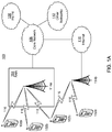
- FIGS 1A-1F are block diagrams illustrating an example communications system 100 in which one or more embodiments may be implemented.
- the communications system 100 may be a multiple access system that provides content, such as voice, data, video, messaging, broadcast, etc., to multiple wireless users.
- the communications system 100 may enable multiple wireless users to access such content through the sharing of system resources, including wireless bandwidth.
- the communications systems 100 may employ one or more channel access methods, such as code division multiple access (CDMA), time division multiple access (TDMA), frequency division multiple access (FDMA), orthogonal FDMA (OFDMA), single-carrier FDMA (SC-FDMA), and the like.
- CDMA code division multiple access
- TDMA time division multiple access
- FDMA frequency division multiple access
- OFDMA orthogonal FDMA
- SC-FDMA single-carrier FDMA
- the communications system 100 may include wireless transmit/receive units (WTRUs) 102a, 102b, 102c, 102d, a radio access network (RAN) 104, a core network 106, a public switched telephone network (PSTN) 108, the Internet 110, and other networks 112, though it will be appreciated that the disclosed embodiments contemplate any number of WTRUs, base stations, networks, and/or network elements.
- WTRUs 102a, 102b, 102c, 102d may be any type of device configured to operate and/or communicate in a wireless environment.
- the WTRUs 102a, 102b, 102c, 102d may be configured to transmit and/or receive wireless signals and may include user equipment (UE), a mobile station, a fixed or mobile subscriber unit, a pager, a cellular telephone, a personal digital assistant (PDA), a smartphone, a laptop, a netbook, a personal computer, a wireless sensor, consumer electronics, and the like.
- UE user equipment
- PDA personal digital assistant
- smartphone a laptop
- netbook a personal computer
- a wireless sensor consumer electronics, and the like.
- the communications systems 100 may also include a base station 114a and a base station 114b.
- Each of the base stations 114a, 114b may be any type of device configured to wirelessly interface with at least one of the WTRUs 102a, 102b, 102c, 102d to facilitate access to one or more communication networks, such as the core network 106, the Internet 110, and/or the networks 112.
- the base stations 114a, 114b may be a base transceiver station (BTS), a Node-B, an eNode B, a Home Node B, a Home eNode B, a site controller, an access point (AP), a wireless router, and the like. While the base stations 114a, 114b are each depicted as a single element, it will be appreciated that the base stations 114a, 114b may include any number of interconnected base stations and/or network elements.
- the base station 114a may be part of the RAN 104, which may also include other base stations and/or network elements (not shown), such as a base station controller (BSC), a radio network controller (RNC), relay nodes, etc.
- BSC base station controller
- RNC radio network controller
- the base station 114a and/or the base station 114b may be configured to transmit and/or receive wireless signals within a particular geographic region, which may be referred to as a cell (not shown).
- the cell may further be divided into cell sectors.
- the cell associated with the base station 114a may be divided into three sectors.
- the base station 114a may include three transceivers, i.e., one for each sector of the cell.
- the base station 114a may employ multiple-input multiple output (MIMO) technology and, therefore, may utilize multiple transceivers for each sector of the cell.
- MIMO multiple-input multiple output
- the base stations 114a, 114b may communicate with one or more of the WTRUs 102a, 102b, 102c, 102d over an air interface 116, which may be any suitable wireless communication link (e.g., radio frequency (RF), microwave, infrared (IR), ultraviolet (UV), visible light, etc.).
- the air interface 116 may be established using any suitable radio access technology (RAT).
- RAT radio access technology
- the communications system 100 may be a multiple access system and may employ one or more channel access schemes, such as CDMA, TDMA, FDMA, OFDMA, SC-FDMA, and the like.
- the base station 114a in the RAN 104 and the WTRUs 102a, 102b, 102c may implement a radio technology such as Universal Mobile Telecommunications System (UMTS) Terrestrial Radio Access (UTRA), which may establish the air interface 116 using wideband CDMA (WCDMA).
- WCDMA may include communication protocols such as High-Speed Packet Access (HSPA) and/or Evolved HSPA (HSPA+).
- HSPA may include High-Speed Downlink Packet Access (HSDPA) and/or High-Speed Uplink Packet Access (HSUPA).
- the base station 114a and the WTRUs 102a, 102b, 102c may implement a radio technology such as Evolved UMTS Terrestrial Radio Access (E-UTRA), which may establish the air interface 116 using Long Term Evolution (LTE) and/or LTE-Advanced (LTE-A).
- E-UTRA Evolved UMTS Terrestrial Radio Access
- LTE Long Term Evolution
- LTE-A LTE-Advanced
- the base station 114a and the WTRUs 102a, 102b, 102c may implement radio technologies such as IEEE 802.16 (i.e., Worldwide Interoperability for Microwave Access (WiMAX)), CDMA2000, CDMA2000 1X, CDMA2000 EV-DO, Interim Standard 2000 (IS-2000), Interim Standard 95 (IS-95), Interim Standard 856 (IS-856), Global System for Mobile communications (GSM), Enhanced Data rates for GSM Evolution (EDGE), GSM EDGE (GERAN), and the like.
- IEEE 802.16 i.e., Worldwide Interoperability for Microwave Access (WiMAX)
- CDMA2000, CDMA2000 1X, CDMA2000 EV-DO Code Division Multiple Access 2000
- IS-95 Interim Standard 95
- IS-856 Interim Standard 856
- GSM Global System for Mobile communications
- GSM Global System for Mobile communications
- EDGE Enhanced Data rates for GSM Evolution
- GERAN GSM EDGERAN
- the base station 114b in Figure 1A may be a wireless router, Home Node B, Home eNode B, or access point, for example, and may utilize any suitable RAT for facilitating wireless connectivity in a localized area, such as a place of business, a home, a vehicle, a campus, and the like.
- the base station 114b and the WTRUs 102c, 102d may implement a radio technology such as IEEE 802.11 to establish a wireless local area network (WLAN).
- the base station 114b and the WTRUs 102c, 102d may implement a radio technology such as IEEE 802.15 to establish a wireless personal area network (WPAN).
- WLAN wireless local area network
- WPAN wireless personal area network
- the base station 114b and the WTRUs 102c, 102d may utilize a cellular-based RAT (e.g., WCDMA, CDMA2000, GSM, LTE, LTE-A, etc.) to establish a picocell or femtocell.
- a cellular-based RAT e.g., WCDMA, CDMA2000, GSM, LTE, LTE-A, etc.
- the base station 114b may have a direct connection to the Internet 110.
- the base station 114b may not be required to access the Internet 110 via the core network 106.
- the RAN 104 may be in communication with the core network 106, which may be any type of network configured to provide voice, data, applications, and/or voice over internet protocol (VoIP) services to one or more of the WTRUs 102a, 102b, 102c, 102d.
- the core network 106 may provide call control, billing services, mobile location-based services, pre-paid calling, Internet connectivity, video distribution, etc., and/or perform high-level security functions, such as user authentication.
- the RAN 104 and/or the core network 106 may be in direct or indirect communication with other RANs that employ the same RAT as the RAN 104 or a different RAT.
- the core network 106 may also be in communication with another RAN (not shown) employing a GSM radio technology.
- the core network 106 may also serve as a gateway for the WTRUs 102a, 102b, 102c, 102d to access the PSTN 108, the Internet 110, and/or other networks 112.
- the PSTN 108 may include circuit-switched telephone networks that provide plain old telephone service (POTS).
- POTS plain old telephone service
- the Internet 110 may include a global system of interconnected computer networks and devices that use common communication protocols, such as the transmission control protocol (TCP), user datagram protocol (UDP) and the internet protocol (IP) in the TCP/IP internet protocol suite.
- the networks 112 may include wired or wireless communications networks owned and/or operated by other service providers.
- the networks 112 may include another core network connected to one or more RANs, which may employ the same RAT as the RAN 104 or a different RAT.
- the WTRUs 102a, 102b, 102c, 102d in the communications system 100 may include multi-mode capabilities, i.e., the WTRUs 102a, 102b, 102c, 102d may include multiple transceivers for communicating with different wireless networks over different wireless links.
- the WTRU 102c shown in Figure 1A may be configured to communicate with the base station 114a, which may employ a cellular-based radio technology, and with the base station 114b, which may employ an IEEE 802 radio technology.
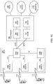
- FIG. 1B is a system diagram illustrating an example WTRU 102.
- the WTRU 102 may include a processor 118, a transceiver 120, a transmit/receive element 122, a speaker/microphone 124, a keypad 126, a display/touchpad 128, non-removable memory 19, removable memory 132, a power source 134, a global positioning system (GPS) chipset 136, and other peripherals 138.
- GPS global positioning system
- the processor 118 may be a general purpose processor, a special purpose processor, a conventional processor, a digital signal processor (DSP), a plurality of microprocessors, one or more microprocessors in association with a DSP core, a controller, a microcontroller, Application Specific Integrated Circuits (ASICs), Field Programmable Gate Array (FPGAs) circuits, any other type of integrated circuit (IC), a state machine, and the like.
- the processor 118 may perform signal coding, data processing, power control, input/output processing, and/or any other functionality that enables the WTRU 102 to operate in a wireless environment.
- the processor 118 may be coupled to the transceiver 120, which may be coupled to the transmit/receive element 122. While Figure 1B depicts the processor 118 and the transceiver 120 as separate components, it will be appreciated that the processor 118 and the transceiver 120 may be integrated together in an electronic package or chip.
- the transmit/receive element 122 may be configured to transmit signals to, or receive signals from, a base station (e.g., the base station 114a) over the air interface 116.
- a base station e.g., the base station 114a
- the transmit/receive element 122 may be an antenna configured to transmit and/or receive RF signals.
- the transmit/receive element 122 may be an emitter/detector configured to transmit and/or receive IR, UV, or visible light signals, for example.
- the transmit/receive element 122 may be configured to transmit and receive both RF and light signals. It will be appreciated that the transmit/receive element 122 may be configured to transmit and/or receive any combination of wireless signals.
- the WTRU 102 may include any number of transmit/receive elements 122. More specifically, the WTRU 102 may employ MIMO technology. Thus, in one embodiment, the WTRU 102 may include two or more transmit/receive elements 122 (e.g., multiple antennas) for transmitting and receiving wireless signals over the air interface 116.
- the transceiver 120 may be configured to modulate the signals that are to be transmitted by the transmit/receive element 122 and to demodulate the signals that are received by the transmit/receive element 122.
- the WTRU 102 may have multi-mode capabilities.
- the transceiver 120 may include multiple transceivers for enabling the WTRU 102 to communicate via multiple RATs, such as UTRA and IEEE 802.11, for example.
- the processor 118 of the WTRU 102 may be coupled to, and may receive user input data from, the speaker/microphone 124, the keypad 126, and/or the display/touchpad 128 (e.g., a liquid crystal display (LCD) display unit or organic light-emitting diode (OLED) display unit).
- the processor 118 may also output user data to the speaker/microphone 124, the keypad 126, and/or the display/touchpad 128.
- the processor 118 may access information from, and store data in, any type of suitable memory, such as the non-removable memory 19 and/or the removable memory 132.
- the non-removable memory 19 may include random-access memory (RAM), read-only memory (ROM), a hard disk, or any other type of memory storage device.
- the removable memory 132 may include a subscriber identity module (SIM) card, a memory stick, a secure digital (SD) memory card, and the like.
- SIM subscriber identity module
- SD secure digital
- the processor 118 may access information from, and store data in, memory that is not physically located on the WTRU 102, such as on a server or a home computer (not shown).
- the processor 118 may receive power from the power source 134, and may be configured to distribute and/or control the power to the other components in the WTRU 102.
- the power source 134 may be any suitable device for powering the WTRU 102.
- the power source 134 may include one or more dry cell batteries (e.g., nickel-cadmium (NiCd), nickel-zinc (NiZn), nickel metal hydride (NiMH), lithium-ion (Li-ion), etc.), solar cells, fuel cells, and the like.
- the processor 118 may also be coupled to the GPS chipset 136, which may be configured to provide location information (e.g., longitude and latitude) regarding the current location of the WTRU 102.
- location information e.g., longitude and latitude
- the WTRU 102 may receive location information over the air interface 116 from a base station (e.g., base stations 114a, 114b) and/or determine its location based on the timing of the signals being received from two or more nearby base stations. It will be appreciated that the WTRU 102 may acquire location information by way of any suitable location-determination method while remaining consistent with an embodiment.
- the processor 118 may further be coupled to other peripherals 138, which may include one or more software and/or hardware modules that provide additional features, functionality and/or wired or wireless connectivity.
- the peripherals 138 may include an accelerometer, an e-compass, a satellite transceiver, a digital camera (for photographs or video), a universal serial bus (USB) port, a vibration device, a television transceiver, a hands free headset, a Bluetooth® module, a frequency modulated (FM) radio unit, a digital music player, a media player, a video game player module, an Internet browser, and the like.
- the peripherals 138 may include an accelerometer, an e-compass, a satellite transceiver, a digital camera (for photographs or video), a universal serial bus (USB) port, a vibration device, a television transceiver, a hands free headset, a Bluetooth® module, a frequency modulated (FM) radio unit, a digital music player, a media player, a video game player
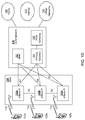
- FIG. 1C is a system diagram illustrating the RAN 104 and the core network 106 according to an embodiment.
- the RAN 104 may employ a UTRA radio technology to communicate with the WTRUs 102a, 102b, 102c over the air interface 116.
- the RAN 104 may also be in communication with the core network 106.
- the RAN 104 may include Node-Bs 140a, 140b, 140c, which may each include one or more transceivers for communicating with the WTRUs 102a, 102b, 102c over the air interface 116.
- the Node-Bs 140a, 140b, 140c may each be associated with a particular cell (not shown) within the RAN 104.
- the RAN 104 may also include RNCs 142a, 142b. It will be appreciated that the RAN 104 may include any number of Node-Bs and RNCs while remaining consistent with an example.
- the Node-Bs 140a, 140b may be in communication with the RNC 142a. Additionally, the Node-B 140c may be in communication with the RNC 142b.
- the Node-Bs 140a, 140b, 140c may communicate with the respective RNCs 142a, 142b via an Iub interface.
- the RNCs 142a, 142b may be in communication with one another via an Iur interface.
- Each of the RNCs 142a, 142b may be configured to control the respective Node-Bs 140a, 140b, 140c to which it is connected.
- each of the RNCs 142a, 142b may be configured to carry out or support other functionality, such as outer loop power control, load control, admission control, packet scheduling, handover control, macrodiversity, security functions, data encryption, and the like.
- the core network 106 shown in Figure 1C may include a media gateway (MGW) 144, a mobile switching center (MSC) 146, a serving GPRS support node (SGSN) 148, and/or a gateway GPRS support node (GGSN) 150. While each of the foregoing elements are depicted as part of the core network 106, it will be appreciated that any one of these elements may be owned and/or operated by an entity other than the core network operator.
- MGW media gateway
- MSC mobile switching center
- SGSN serving GPRS support node
- GGSN gateway GPRS support node
- the RNC 142a in the RAN 104 may be connected to the MSC 146 in the core network 106 via an IuCS interface.
- the MSC 146 may be connected to the MGW 144.
- the MSC 146 and the MGW 144 may provide the WTRUs 102a, 102b, 102c with access to circuit-switched networks, such as the PSTN 108, to facilitate communications between the WTRUs 102a, 102b, 102c and traditional land-line communications devices.
- the RNC 142a in the RAN 104 may also be connected to the SGSN 148 in the core network 106 via an IuPS interface.
- the SGSN 148 may be connected to the GGSN 150.
- the SGSN 148 and the GGSN 150 may provide the WTRUs 102a, 102b, 102c with access to packet-switched networks, such as the Internet 110, to facilitate communications between and the WTRUs 102a, 102b, 102c and IP-enabled devices.
- the core network 106 may also be connected to the networks 112, which may include other wired or wireless networks that are owned and/or operated by other service providers.
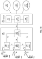
- Figure 1D is a system diagram illustrating the RAN 104 and the core network 106 according to an embodiment.
- the RAN 104 may employ an E-UTRA radio technology to communicate with the WTRUs 102a, 102b, 102c over the air interface 116.
- the RAN 104 may also be in communication with the core network 106.
- the RAN 104 may include eNode-Bs 140a, 140b, 140c, though it will be appreciated that the RAN 104 may include any number of eNode-Bs while remaining consistent with an embodiment.
- the eNode-Bs 140a, 140b, 140c may each include one or more transceivers for communicating with the WTRUs 102a, 102b, 102c over the air interface 116.
- the eNode-Bs 140a, 140b, 140c may implement MIMO technology.
- the eNode-B 140a for example, may use multiple antennas to transmit wireless signals to, and receive wireless signals from, the WTRU 102a.
- Each of the eNode-Bs 140a, 140b, 140c may be associated with a particular cell (not shown) and may be configured to handle radio resource management decisions, handover decisions, scheduling of users in the uplink and/or downlink, and the like. As shown in Figure 1D , the eNode-Bs 140a, 140b, 140c may communicate with one another over an X2 interface.
- the core network 106 shown in Figure 1D may include a mobility management gateway (MME) 142, a serving gateway 144, and a packet data network (PDN) gateway 146. While each of the foregoing elements are depicted as part of the core network 106, it will be appreciated that any one of these elements may be owned and/or operated by an entity other than the core network operator.
- MME mobility management gateway
- PDN packet data network
- the MME 142 may be connected to each of the eNode-Bs 140a, 140b, 140c in the RAN 104 via an S1 interface and may serve as a control node.
- the MME 142 may be responsible for authenticating users of the WTRUs 102a, 102b, 102c, bearer activation/deactivation, selecting a particular serving gateway during an initial attach of the WTRUs 102a, 102b, 102c, and the like.
- the MME 142 may also provide a control plane function for switching between the RAN 104 and other RANs (not shown) that employ other radio technologies, such as GSM or WCDMA.
- the serving gateway 144 may be connected to each of the eNode Bs 140a, 140b, 140c in the RAN 104 via the S1 interface.
- the serving gateway 144 may generally route and forward user data packets to/from the WTRUs 102a, 102b, 102c.
- the serving gateway 144 may also perform other functions, such as anchoring user planes during inter-eNode B handovers, triggering paging when downlink data is available for the WTRUs 102a, 102b, 102c, managing and storing contexts of the WTRUs 102a, 102b, 102c, and the like.
- the serving gateway 144 may also be connected to the PDN gateway 146, which may provide the WTRUs 102a, 102b, 102c with access to packet-switched networks, such as the Internet 110, to facilitate communications between the WTRUs 102a, 102b, 102c and IP-enabled devices.
- the PDN gateway 146 may provide the WTRUs 102a, 102b, 102c with access to packet-switched networks, such as the Internet 110, to facilitate communications between the WTRUs 102a, 102b, 102c and IP-enabled devices.
- the core network 106 may facilitate communications with other networks.
- the core network 106 may provide the WTRUs 102a, 102b, 102c with access to circuit-switched networks, such as the PSTN 108, to facilitate communications between the WTRUs 102a, 102b, 102c and traditional land-line communications devices.
- the core network 106 may include, or may communicate with, an IP gateway (e.g., an IP multimedia subsystem (IMS) server) that serves as an interface between the core network 106 and the PSTN 108.
- IMS IP multimedia subsystem
- the core network 106 may provide the WTRUs 102a, 102b, 102c with access to the networks 112, which may include other wired or wireless networks that are owned and/or operated by other service providers.
- FIG. 1E is a system diagram illustrating the RAN 104 and the core network 106 according to an embodiment.
- the RAN 104 may be an access service network (ASN) that employs IEEE 802.16 radio technology to communicate with the WTRUs 102a, 102b, 102c over the air interface 116.
- ASN access service network
- the communication links between the different functional entities of the WTRUs 102a, 102b, 102c, the RAN 104, and the core network 106 may be defined as reference points.
- the RAN 104 may include base stations 140a, 140b, 140c, and an ASN gateway 142, though it will be appreciated that the RAN 104 may include any number of base stations and ASN gateways while remaining consistent with an embodiment.
- the base stations 140a, 140b, 140c may each be associated with a particular cell (not shown) in the RAN 104 and may each include one or more transceivers for communicating with the WTRUs 102a, 102b, 102c over the air interface 116.
- the base stations 140a, 140b, 140c may implement MIMO technology.
- the base station 140a for example, may use multiple antennas to transmit wireless signals to, and receive wireless signals from, the WTRU 102a.
- the base stations 140a, 140b, 140c may also provide mobility management functions, such as handoff triggering, tunnel establishment, radio resource management, traffic classification, quality of service (QoS) policy enforcement, and the like.
- the ASN gateway 142 may serve as a traffic aggregation point and may be responsible for paging, caching of subscriber profiles, routing to the core network 106, and the like.
- the air interface 116 between the WTRUs 102a, 102b, 102c and the RAN 104 may be defined as an R1 reference point that implements the IEEE 802.16 specification.
- each of the WTRUs 102a, 102b, 102c may establish a logical interface (not shown) with the core network 106.
- the logical interface between the WTRUs 102a, 102b, 102c and the core network 106 may be defined as an R2 reference point, which may be used for authentication, authorization, IP host configuration management, and/or mobility management.
- the communication link between each of the base stations 140a, 140b, 140c may be defined as an R8 reference point that includes protocols for facilitating WTRU handovers and the transfer of data between base stations.
- the communication link between the base stations 140a, 140b, 140c and the ASN gateway 215 may be defined as an R6 reference point.
- the R6 reference point may include protocols for facilitating mobility management based on mobility events associated with each of the WTRUs 102a, 102b, 102c.
- the RAN 104 may be connected to the core network 106.
- the communication link between the RAN 104 and the core network 106 may be defined as an R3 reference point that includes protocols for facilitating data transfer and mobility management capabilities, for example.
- the core network 106 may include a mobile IP home agent (MIP-HA) 144, an authentication, authorization, accounting (AAA) server 146, and a gateway 148. While each of the foregoing elements are depicted as part of the core network 106, it will be appreciated that any one of these elements may be owned and/or operated by an entity other than the core network operator.
- MIP-HA mobile IP home agent
- AAA authentication, authorization, accounting
- the MIP-HA may be responsible for IP address management, and may enable the WTRUs 102a, 102b, 102c to roam between different ASNs and/or different core networks.
- the MIP-HA 144 may provide the WTRUs 102a, 102b, 102c with access to packet-switched networks, such as the Internet 110, to facilitate communications between the WTRUs 102a, 102b, 102c and IP-enabled devices.
- the AAA server 146 may be responsible for user authentication and for supporting user services.
- the gateway 148 may facilitate interworking with other networks.
- the gateway 148 may provide the WTRUs 102a, 102b, 102c with access to circuit-switched networks, such as the PSTN 108, to facilitate communications between the WTRUs 102a, 102b, 102c and traditional land-line communications devices.
- the gateway 148 may provide the WTRUs 102a, 102b, 102c with access to the networks 112, which may include other wired or wireless networks that are owned and/or operated by other service providers.
- the RAN 104 may be connected to other ASNs and the core network 106 may be connected to other core networks.
- the communication link between the RAN 104 the other ASNs may be defined as an R4 reference point, which may include protocols for coordinating the mobility of the WTRUs 102a, 102b, 102c between the RAN 104 and the other ASNs.
- the communication link between the core network 106 and the other core networks may be defined as an R5 reference, which may include protocols for facilitating interworking between home core networks and visited core networks.
- the communications network 100 may be adapted for Coordinated Multi-Point transmission and reception (CoMP).
- CoMP in general, may refer to a mode of transmission and reception in which multiple spatially-diverse transmission (Tx) points, through some form of coordination, transmit signals (transmissions) to a receiver, such as a WTRU, provisioned or otherwise equipped to receive such coordinated downlink transmissions.
- Tx point may refer to any antenna port or subset of geographically co-located antenna ports from a network that may be transmitting to, or receiving from the WTRU.
- a set of Tx points configured or activated for a given WTRU may or may not belong to the same physical cell identity.
- the Tx point may transmit one channel station information reference signal (CSI-RS) or one set of CSI-RS.
- the Tx point may also transmit one cell-specific reference signal (CRS) or one set of CRS.
- Coordination in general, includes coordination of scheduling and/or transmission parameters, and/or coordination of data delivery, among the spatially-diverse Tx points (or a subset thereof).
- the form of such coordination generally falls within one of a plurality of defined categories for CoMP (CoMP categories).
- CoMP categories may change from one CoMP category to another, as appropriate (e.g., depending on channel conditions and/or movement of the WTRU).
- Examples of the CoMP categories may include Joint Processing (JP) CoMP, and Coordinated Scheduling/Coordinated Beamforming (CS/CB).
- the JP CoMP may include a number of sub-categories, including, for example, Joint Transmission (JT) CoMP, and dynamic point (or cell) selection (DPS).
- JT Joint Transmission
- DPS dynamic point (or cell) selection
- data may be made available at each Tx point of a CoMP cooperating set (i.e., a set of Tx points that may directly or indirectly participate in the coordinated downlink transmissions, including, for example, corresponding physical downlink shared channels (PDSCHs) of the coordinated downlink transmissions).
- PDSCHs physical downlink shared channels
- multiple Tx points of CoMP cooperating set may be scheduled to and actively transmit the coordinated downlink transmissions at or within a given time period (e.g., simultaneously).
- the multiple Tx points actively transmitting the coordinated downlink transmissions may be a subset of or the entire CoMP cooperating set. This transmission method may coherently or non-coherently improve the received signal quality of the WTRU 102 and/or actively cancel interference for other WTRUs.
- each of the coordinated downlink transmissions is scheduled and transmitted from one CoMP Tx point within the CoMP cooperating set at a time (e.g., every subframe).
- the Tx point selected to be the CoMP Tx point for the DPS coordinated downlink transmissions may change dynamically within the CoMP cooperating set.
- the serving cell or serving Tx point may refer to a cell (or Tx point thereof) adapted to transmit physical downlink control channel (PDCCH) or enhanced PDCCH (E-PDCCH) assignments, and such cell or Tx point may be, for example, a single cell.
- PDCH physical downlink control channel
- E-PDCCH enhanced PDCCH
- User scheduling and/or beamforming decisions may be made with coordination among cells corresponding to the CoMP cooperating set.
- the WTRU 102 may decode a PDCCH or an E-PDCCH based on the knowledge of the antenna port (or set thereof) and associated reference signal (e.g., CRS or DM-RS) only, and might not require knowledge of the actual Tx point used for the transmission of such signals.
- CRS C-RNTI
- DM-RS DM-RS
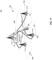
- FIG. 1F is a block diagram illustrating an example CoMP network 180 for use with a communications system, such as, the communications system 100.
- the CoMP network 180 may include a CoMP cooperating set 182 and a CoMP controller 184.
- the CoMP cooperating set 182 may include spatially-diverse Tx points 114a-114d (e.g., geographically-separated base stations, eNBs, etc.) that may directly or indirectly participate in the coordinated downlink transmissions to the WTRU 102, including, for example, forming one or more PDSCHs of the coordinated downlink transmissions for reception by the WTRU 102.
- the Tx points 114a-114d may be communicatively coupled with the CoMP controller 184, via, for example, fast backhauls and/or X2 interfaces.
- the Tx points 114a-114d may define respective cells, namely, serving cell 186a of WTRU 102 and non-serving cells 186b-186d.
- the serving cell 186a may transmit to the WTRU 102 various information to enable the WTRU 102 to receive the coordinated downlink transmissions, such as, for example, PDCCH assignments; downlink control information (DCI); information for signaling to the WTRU 102 to receive the coordinated downlink transmissions from the CoMP Tx points, including the CoMP Tx points other than the serving cell; and the like.
- the Tx points 114a-114d may also logically belong to the same cell. In this case, the Tx points 114a-114d may transmit the same set of common reference signals (CRS), but transmit other reference signals (such as, CSI-RS and/or DM-RS) according to point-specific parameters.
- CRS common reference signals
- the Tx points 114a-114d may include respective sets of cell-specific system parameters corresponding to their respective cells 182a-182d, and/or point-specific parameters.
- Each set of cell-specific system parameters may include, for example, a cell identifier associated with the corresponding cell (cell ID), a timeslot index within a radio frame associated with the coordinated downlink transmission and/or a scrambling identity (scrambling ID) associated with the corresponding cell (cell-specific scrambling ID).
- a set of point-specific parameters may include a set of CSI-RS configuration parameters, possibly including an identifier for the transmission point.
- the Tx points 114a-114d may use their respective sets of cell-specific system parameters and/or point-specific parameters to generate and transmit the coordinated downlink transmissions and/or associated control information to the WTRU 102.
- the cell-specific system parameters may be used with various processes for (i) scrambling the PDSCH of the coordinated downlink transmissions, (ii) determining appropriate usage of ports for UE-specific and/or demodulation reference signals (collectively "DM-RS"); (iii) scrambling of DM-RS sequences; (iv) precoding of the coordinated downlink transmissions and DM-RS, (v) assigning the PDCCH(s) to assign the PDSCH(s) of the coordinated downlink transmissions.
- DM-RS demodulation reference signals
- the DM-RS may be present and/or be a valid reference for the WTRU 102 to use with performing demodulation of the PDSCH(s) if the PDSCH(s) of the coordinated downlink transmissions are associated with the corresponding antenna port(s).
- the pseudo-random sequence c ( i ) may be defined by, for example, a length-31 Gold sequence.
- This length-31 Gold sequence may be, for example, the length-31 Gold sequence set forth in LTE-A.
- the n SCID may be a scrambling ID specified in DCI associated with the PDSCH(s) of the coordinated downlink transmissions, such as, for example, specified in a scrambling ID field of DCI format 2B or 2C.
- the n SCID may be zero for antenna ports 7 or 8, such as when there is no DCI format 2B or 2C associated with the PDSCH(s) of the coordinated downlink transmissions.
- the n SCID for antenna ports 9 to 14 may be zero, as well.
- the WTRU 102 may be configured with one or more values for the parameter X ID that may be specific to the concerned WTRU 102.
- Each of the X ID values may be part of a set of reception parameters to use for reception of a coordinated downlink transmission.
- the WTRU 102 may select the value for X ID according to other methods described herein, such as those described for the selection of a set of reception parameters to use for the reception of a coordinated downlink transmission.
- the WTRU 102 may then use the selected value for X ID (e.g., instead of N ID cell ).
- One of the configured values of X ID may also correspond to the identity of a specific cell.
- the parameter X ID may correspond to a configuration, or to a set of parameters, associated to one or more transmission points, such as a parameter part of, or associated to, a non-zero-power CSI-RS configuration. It may also correspond to a parameter also used in calculation of the scrambling initiator for this non-zero-power CSI-RS configuration.
- the WTRU 102 may be configured with one or more values for the parameter Y ID that may be specific to the concerned WTRU. Each of the Y ID values may be part of a set of reception parameters to use for reception of a coordinated downlink transmission.
- the WTRU 102 may select the value for Y ID according to other methods described herein, such as those described for the selection of a set of reception parameters to use for the reception of a coordinated downlink transmission.
- the WTRU 102 may then use the selected value for Y ID (e.g., instead of the n SCID ).
- the WTRU 102 in various embodiments, may be configured with one or more values for Y ID only for some antenna ports.
- a value of the parameter Y ID may be expressed as a sum of a point-specific or UE-specific parameter (e.g., similar to X ID ) and of the n SCID parameter that may take one of the values 0 or 1.
- the WTRU 102 may dynamically select a set of reception parameters to use for reception of a coordinated downlink transmission in a given subframe, according to methods described herein, including reception of explicit signaling information and/or implicit selection methods and/or based on what set of reception parameters is activated in the concerned subframe.
- the WTRU 102 may possibly use different combinations for X ID and Y ID from one subframe to another. This may have a benefit of introducing a possibility for the network of scheduling, in a flexible manner, different sets of WTRUs using orthogonal DM-RS when needed.
- the Orthogonal DM-RS may be scrambled using the same pair of X ID and Y ID parameters for the scrambling initiator. For instance, a pair of WTRUs that are both relatively close to a given Tx point may utilize the same pair of X ID and Y ID parameters when co-scheduled in the same resource block and subframe.
- the scrambling sequence generator of each CoMP Tx point may be initialized at the start of each subframe with an initialization value c init .
- the scrambling sequence generator of each CoMP Tx point may be initialized at the start of each subframe with an initialization value c init .
- RNTI radio network temporary identifier
- Up to two codewords may be transmitted in one subframe, i.e., q ⁇ ⁇ 0,1 ⁇ . In a single codeword transmission example, q may be equal to zero.
- the value used for the parameter N ID cell may correspond to the same value used for the parameter X ID .
- a control region of a subframe k of the coordinated downlink transmissions may include a set of control channel elements (CCEs). These CCEs may be numbered from 0 to N CCE, k -1, where N CCE, k may be a total number of CCEs in the control region of the subframe k .
- the WTRU 102 may monitor PDCCHs at least for subframes for which the WTRU 102 is in discontinuous reception (DRX) Active Time, where monitoring may imply attempting to decode each of the PDCCHs in the set according to all the monitored DCI formats.
- DRX discontinuous reception
- the set of PDCCH candidates to monitor may be defined in terms of search spaces, where a search space S k L at aggregation level L ⁇ ⁇ 1,2,4,8 ⁇ may be defined by a set of PDCCH candidates.
- M ( L ) may be the number of PDCCH candidates to monitor in the search space.
- the WTRU 102 may monitor one common search space at each of the aggregation levels 4 and 8 and one WTRU-specific search space at each of the aggregation levels 1, 2, 4, 8.
- the common and WTRU-specific search spaces may overlap.
- the aggregation levels defining the search spaces are listed in Table 1.
- the DCI formats that the WTRU 102 may monitor depend on the configured transmission mode.
- Table 1 shows example PDCCH candidates that may be monitored by a WTRU.
- Table 1 Search space S k L Number of PDCCH candidates M ( L ) Type Aggregation level L Size [in CCEs] WTRU-specific 1 6 6 2 12 6 4 8 2 8 16 2 Common 4 16 4 8 16 2
- the CoMP Tx points may use DM-RS based precoding and channel state information reference signal (CSI-RS) based CSI feedback. It is contemplated that the operation of DL MIMO may become more dependent on DM-RS and CSI-RS and less dependent on a common reference signal (CRS).
- the WTRU 102 may be configured to monitor DCI formats 2C and 1A in the PDCCH search spaces. An example of information that may be transmitted using DCI format 2C is shown in Table 2.
- the information that may be transmitted using DCI format 2C may include, for transport block 1, a modulation and coding scheme (MCS), which may be 5 bits; a new data indicator, which may be 1 bit; and a redundancy version, which may be 2 bits.
- MCS modulation and coding scheme
- the information that may be transmitted using DCI format 2C may include a MCS, which may be 5 bits; a new data indicator, which may be 1 bit; and a redundancy version, which may be 2 bits.
- Table 4 Information Field Bit Number Carrier indicator 0 or 3 bits Flag for format0/format1A differentiation 1 bit, where value 0 may indicate format 0, and value 1 may indicate format 1A
- VRB virtual resource block
- MCS Modulation and coding scheme
- 5 bits HARQ process number 3 bits (FDD example), 4 bits (TDD example)
- New data indicator (NDI) 1 bit Redundancy version (RV) 2 bits
- TPC command for PUCCH 2 bits Downlink Assignment Index (for TDD examples) 2 bits
- the Tx points 114a-114d may include respective CoMP controller modules (not shown) that interface with the CoMP controller 184.
- the CoMP controller modules may exchange information directly, via fast backhauls and/or X2 interfaces; or indirectly via the CoMP controller 184. This information may be used to facilitate configuration of the Tx points 114a-114d for CoMP, and/or to facilitate coordination and/or scheduling of coordinated downlink transmissions from the Tx points 114a-114d to the WTRU 102.
- the information exchanged among the CoMP controller modules may include configuration information for selecting (e.g., dynamically), from the CoMP cooperating set 182, the CoMP Tx points for the coordinated downlink transmissions.
- the information may also include, for example, scheduling information for scheduling the CoMP Tx points for JT and/or DPS CoMP, as appropriate.
- the CoMP controller modules may also obtain and/or configure each of the Tx points 114a-114d (or at least each of the CoMP Tx points) with a common set of system parameters and/or point-specific parameters.
- the common set of parameters may be used by the Tx points 114a-114d points to generate and transmit the coordinated downlink transmissions.
- the common set of parameters used by each of the CoMP Tx points may make the coordinated downlink transmissions from such different CoMP Tx points appear to emanate from the same source (e.g., the use of different CoMP Tx points may be transparent to the WTRU 102; and demodulation of the PDSCH(s) may be transparent as in single-cell MIMO in LTE, for example.).
- the common system parameters may include, for example, a common DM-RS sequence, a common set of DM-RS (i.e., antenna) ports, a common identifier (common ID), a common slot number and/or a common scrambling ID (common scrambling ID).
- Each of the common system parameters may be based on an arbitrary number, for example.
- n s_common is slot number associated with the coordinated downlink transmissions
- N ID common corresponds to the common identifier
- n SCID_common corresponds to the common scrambling ID.
- N ID common may, for example, correspond to the parameter X ID
- n SCID_common may, for example, correspond to the parameter Y ID .
- the common set of system parameters may be signaled to the WTRU 102 using a combination of physical layer and/or higher layer signaling, or alternatively, information for signaling to the WTRU to select and/or determine the common set of system parameters for use in receiving the coordinated downlink transmission may be transmitted to the WTRU 102.
- Such signaling and/or information transmission may occur, for example, when the CoMP cooperating set is configured or reconfigured.
- the WTRU 102 may be aware that JP CoMP is applied for each scheduled PDSCH, and the Tx points may schedule the PDSCH using the PDCCH assignment process described above.
- the Tx point may modify the set of parameters (e.g. the common set of system parameters) used for PDSCH scrambling depending on which WTRU or set of WTRUs it is transmitting to in a specific resource block and subframe.
- the common set of system parameters may include the cell-specific set of system parameters of the serving cell (serving-cell system parameters); a set of system parameters based on the CoMP cooperating set (CoMP-set system parameters); a set of system parameters based, at least in part, on the serving-cell system parameters and the CoMP-set system parameters; a set of system parameters based, at least in part, on the cell-specific set of system parameters of the CoMP Tx points other than the serving cell (non-serving-cell Tx point system parameters); a set of system parameters based, at least in part, on the serving-cell system parameters, the CoMP-set system parameters and the non-serving-cell Tx point system parameters; and combinations thereof.
- the common set of system parameters may include other parameters, as well.
- the CoMP-set system parameters may include, for example, a common DM-RS sequence, a common set of DM-RS ports, an identifier associated with the CoMP cooperating set (CoMP-set ID), a timeslot index within a radio frame associated with the coordinated downlink transmission and/or a scrambling ID associated with the CoMP cooperating set (CoMP-set scrambling ID).
- n s_CoMP set is timeslot index within a radio frame associated with the coordinated downlink transmission
- N ID C o M P set corresponds to the CoMP-set ID
- n SCID_CoMP set corresponds to the CoMP-set scrambling ID.
- N ID C o M P set may correspond to the parameter X ID
- n SCID_CoMP set may correspond to the parameter Y ID
- N ID CoMP set may also correspond to the parameter X ID .
- the CoMP-set system parameters may be signaled to the WTRU 102 using a combination of physical layer and/or higher layer signaling, or alternatively, information for signaling to the WTRU to select and/or determine the CoMP-set system parameters for use in receiving the coordinated downlink transmission may be transmitted to the WTRU 102.
- Such signaling and/or information transmission may occur, for example, when the CoMP cooperating set is configured or reconfigured. Responsive to such signaling, the WTRU 102 may be aware that JP CoMP is applied for each scheduled PDSCH, and the Tx points may schedule the PDSCH using the PDCCH assignment process described above.
- any of the Tx points may modify the set of parameters (e.g., the CoMP-set system parameters, or whether the set of system parameters corresponds to the "common set” or the "CoMP-set” system parameters) used for PDSCH scrambling depending on which WTRU or set of WTRUs it is transmitting to in a specific resource block and subframe.
- the set of parameters e.g., the CoMP-set system parameters, or whether the set of system parameters corresponds to the "common set” or the "CoMP-set” system parameters
- the serving-cell system parameters may include, for example, a common DM-RS sequence, a common set of DM-RS (i.e., antenna) ports, the cell ID, a timeslot index within a radio frame associated with the coordinated downlink transmission and/or the serving-cell scrambling ID.
- n s _ serving cell is the slot number associated with the coordinated downlink transmissions
- N ID s e r v i n g cell corresponds to the cell ID
- n SCID_serving cell corresponds to the serving-cell scrambling ID.
- N ID s e r v i n g cell may correspond to the parameter X ID
- n SCID_serving cell may correspond to the parameter Y ID .
- N ID s e r v i n g cell may also correspond to the parameter X ID .
- the serving cell 182a may forward the serving-cell system parameters (e.g., its cell ID and its subframe or timeslot index within a radio frame) to the other Tx points in the CoMP cooperating set.
- the serving cell 182a may do so, for example, when the CoMP cooperating set is configured.
- the serving-cell ID and subframe or timeslot index may be forwarded over the X2 interface.
- the serving cell ID may be acquired during X2 setup, for example using an X2 SETUP procedure, between cells or during an X2 configuration update procedure.
- the other Tx points 114b-114d in the CoMP cooperating set 182 may acquire the information of a serving cell ID through cell planning or other signaling, via, for example, the CoMP controller modules.
- the CoMP controller 184 may be a centralized CoMP controller, as shown, or, alternatively, a distributed CoMP controller, such as, for example, an autonomous distributed CoMP controller.
- the CoMP controller 184 may minimize interference by coordinating scheduling of the coordinated downlink transmissions within the cells, and/or actively suppressing interference using signal processing techniques.
- the coordinated downlink transmissions to each of the WTRU 102, from the CoMP Tx points may be weighted to minimize interference, maximize throughput and/or maximize the SINR of the comp-mode transmissions received at such WTRU 102a.
- the coordinated transmissions may allow the comp network 180 to achieve high spectral efficiencies.
- the WTRU 102 may be configured with one or more sets of parameters; each of which may correspond to a DM-RS.
- the WTRU 102 may use one or more of the sets of parameters to receive the PDSCH(s) of the coordinated downlink transmissions.
- Each set of parameters may include, for example, an antenna port index, initialization values for the DM-RS generator, a transmission mode, and/or a scrambling ID that may be used (in addition to a cell or a common ID) to initialize a DM-RS sequence.
- This scrambling ID may be, for example, any of a scrambling ID configured by upper layers (e.g. RRC), an identity of the WTRU 102, a RNTI, a serving-cell ID, etc.
- the serving-cell ID may be, for example, a servCellID used by the RRC to identify the serving cell, or a Carrier Indicator Field (CIF) that may be used by the physical layer to identify the serving cell, to which serving cell may be associated with a given set of parameters, for example, to a specific DM-RS.
- the set of parameters may be akin to a serving cell (or a PDSCH) of the WTRU configuration.
- the term PDCCH may include a E-PDCCH.
- the CoMP network 180 may include more of fewer Tx points.
- the CoMP network 180 may include one or more remote radio equipments (RREs) instead of, or in addition to, the Tx points 114a-114d.
- RREs remote radio equipments
- Each of the RREs may include a single or multiple antennas; any one of which may be communicatively coupled to the CoMP controller 184 and available as a Tx point for CoMP transmissions.
- the CoMP controller 184 may coordinate the Tx points to permit various CoMP transmissions to the WTRU 102.
- the CoMP transmission network 180 may include both a distributed CoMP controller and a centralized CoMP controller.
- all of the antennas of the Tx points may 114a-114d may be assumed to be communicatively coupled to the CoMP controller 184, and available for use as the Tx points for the coordinated downlink transmissions. In some instances, less than all of the Tx point antennas in any one cell or multiple cells may be used as the Tx points for the coordinated downlink transmissions. In other instances, two or more of the Tx point antennas in any cell may be used as a single Tx point for the coordinated downlink transmission (e.g., for multiple-input multiple-output (MIMO) operation).
- MIMO multiple-input multiple-output
- CoMP set may refer to any of a CoMP operating set, a set of CoMP Tx points, and a CoMP measurement set.
- the CoMP measurement set may be a set of cells for which channel state and/or statistical information is reported.
- the channel state/statistical information may be related to the links between the WTRU 102 and one or more of the Tx points 114a-114d in the CoMP cooperating set 182.
- the CoMP measurement set may be the same as the CoMP cooperating set 182.
- the actual WTRU reports may include feedback for a subset of cells of the CoMP measurement set 182. These cells may be deemed as reported cells.
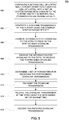
- FIG 2 is a flow diagram illustrating an example process 200 for carrying out a joint processing (JP) coordinated multi-point (CoMP) transmission.
- JP joint processing
- CoMP coordinated multi-point
- the process 200 may be used for various non-transparent JP CoMP transmission schemes, and to enable the WTRU 102 to determine that a forthcoming downlink transmission is a non-transparent coordinated downlink transmission from a CoMP Tx point other than the serving cell of the WTRU 102. Determining that the forthcoming downlink transmission is a non-transparent coordinated downlink transmission of a CoMP Tx point other than the serving cell (non-serving-cell CoMP Tx point) may permit the WTRU 102 to correctly receive such non-transparent coordinated downlink transmission.
- Receiving the forthcoming downlink transmission from the non-serving-cell CoMP Tx point may include any of (i) receiving time-domain orthogonal-frequency-division-multiplexed (OFDM) signals for a set of antenna ports, (ii) converting the time-domain OFDM signals for the set of antenna ports into corresponding modulation symbols for the set of antenna ports, (iii) performing decoding of any precoding of the modulation symbols for the set of antenna ports, (iv) performing layer mapping to map the de-precoded modulation symbols for the set of antenna ports to a set of transmission layers corresponding to the set of antenna ports; (v) demodulating the modulated symbols into scrambled bits, (vi) descrambling the scrambled bits into coded bits of one or more code words, and (vii) forming the code words from the descrambled coded bits.
- OFDM orthogonal-frequency-division-multiplexed
- information for signaling to the WTRU 102 to receive a forthcoming downlink transmission from the non-serving-cell CoMP Tx point may be transmitted to the WTRU 102.
- This signaling information may be transmitted from the Tx point 114a of the serving cell.
- the Tx point 114a may transmit the signaling information using implicit and/or explicit signaling, such as, for example, layer 1 (L1), layer 2 (L2) and/or layer 3 (L3) signaling.
- Tx point 114a may transmit the signaling information in a control region of a downlink control channel (e.g., a PDCCH) for which the WTRU 102 may be configured to perform blind detection.
- the downlink control channel may be associated with the downlink transmission.
- the signaling information may be received at the WTRU 102.
- the WTRU 102 may, for example, receive the signaling information by way of implicit signaling and/or explicit signaling.
- the WTRU 102 may perform blind detection of the control region to obtain the signaling information (which may be any of an implicit and explicit indication).
- Obtaining the signaling information may include the WTRU 102 receiving and/or decoding downlink control information (DCI).
- DCI downlink control information
- the signaling information may be based, at least in part, on one or more characteristics, features, attributes, etc. (collectively “characteristics") of the received DCI and/or the decoded DCI.
- the WTRU 102 may first receive and/or decode the DCI, and then recognize or otherwise interpret the characteristics of the received DCI and/or the decoded DCI.
- the signaling information may be based, at least in part, on information associated with, included within, identified by, and/or referenced by the received and/or decoded DCI.
- the WTRU 102 may first receive and/or decode the DCI, and then recognize or otherwise interpret such information associated with, included within, identified by, and/or referenced by the received and/or decoded DCI to obtain the JP-CoMP indication.
- Examples of the signaling information may include any of (i) an information and/or an indication (collectively "information") based, at least in part, on a resource allocation for the decoded DCI, such as an index of a (e.g., first) control channel element (CCE) of the received DCI; (ii) information based, at least in part, on a physical resource block assignment received in the decoded DCI for a given physical downlink (e.g., a PDSCH) transmission; (iii) information based, at least in part, on a physical downlink control channel (PDCCH) search space for the decoded DCI; (iv) information based, at least in part, on a RNTI used to scramble the decoded DCI; (v) information based, at least in part, on an explicit signaling of a set of parameters in a DCI; (vi) information based, at least in part, on a size of a DCI that may be decoded on a PDCCH
- the signaling information may be obtained by the WTRU 102 according to at least one of the following.
- the WTRU 102 may receive and decode the DCI, and then may interpret the resource allocation for the decoded DCI as an implicit signaling of the signaling information.
- the WTRU 102 may receive and decode the DCI, and then may interpret the physical resource block assignment as the implicit signaling.
- the WTRU 102 may receive and decode the DCI, and then may interpret a characteristic of the PDCCH search space as the implicit signaling. For example, the WTRU 102 may interpret a range of CCEs within a WTRU-specific search space (WTRU-SS) where the valid DCI is received as the implicit signaling, provided that multiple (possibly non-overlapping) WTRU-SS may be defined for the WTRU 102.
- WTRU-SS WTRU-specific search space
- the WTRU 102 may interpret an identity of the WTRU-SS where the valid DCI is received as the implicit signaling, provided that multiple (possibly non-overlapping) WTRU-SS may be defined for the WTRU 102.
- the WTRU 102 may interpret a range of CCEs within a common search space for the WTRU 102 where the valid DCI is received and/or an identity of the common search space for the WTRU 102 where the valid DCI as the implicit signaling.
- the WTRU 102 may receive the DCI. Thereafter, the WTRU 102 may select, from a plurality of RNTIs provisioned into the WTRU 102 (WTRU-specific RNTIs) for decoding the received DCI on the PDCCH, a WTRU-specific RNTI designated for JP CoMP transmissions. Then the WTRU 102 may attempt to decode the DCI using the selected WTRU-specific RNTI, and interpret a successful decoding of the received DCI using the selected WTRU-specific RNTI as the implicit signaling. As an alternative, the WTRU 102 may receive the DCI.
- WTRU-specific RNTIs provisioned into the WTRU 102
- the WTRU 102 may then attempt to decode the received DCI, iteratively, using the plurality of WTRU-specific RNTI, and interpret the received DCI being successfully decoded with the WTRU-specific RNTI designated for JP CoMP transmissions as the implicit signaling.
- the WTRU 102 may receive and decode DCI having one or more indicator bits for indicating JP CoMP transmission, obtain a value for the indicator bits (indicator-bits value), and then may interpret the indicator bits as an explicit signaling to receive the forthcoming downlink transmission from the non-serving-cell CoMP Tx point, provided that the indicator-bits value is indicative of a JP CoMP transmission.
- the WTRU 102 may receive and decode a DCI, determine the size of the DCI (DCI size), and then interpret the DCI size as the implicit signaling, provided that the DCI size is indicative of a JP CoMP transmission.
- the DCI size may be indicative a JP CoMP transmission, for example, if it is different than a size of a DCI used for non-CoMP transmission.
- the WTRU 102 may receive and decode the DCI, obtain the DM-RS ports indices signaled inside the decoded DCI, and then interpret the obtained DM-RS ports indices as explicit signaling to receive the forthcoming downlink transmission from the non-serving-cell CoMP Tx point.
- the signaled indices may be according to any of (i) DM-RS port indices for all or some data and/or each or some codewords; and/or b) DM-RS port indices for each Tx point or each set of Tx points.
- the WTRU 102 may receive, in the downlink control signaling (e.g. DCI format) used for COMP operation, information bits that may correspond to the following information: a) number of transmission points other than serving cell; and b) DM-RS ports indices.
- the DM-RS port indices may be for all data or each codeword. Alternatively, the DM-RS port indices may be for each Tx point or each set of Tx points.
- the WTRU 102 may receive and decode the DCI, obtain the carrier indicator value signaled inside the decoded DCI, and then interpret the obtained carrier indicator value as explicit signaling to receive the forthcoming downlink transmission from the non-serving-cell CoMP Tx point.
- the signaled carrier indicator value may be according to a configuration of the WTRU 102 that associates the value with a set of reception parameters to use for reception of a coordinated downlink transmission in a given subframe.
- the WTRU 102 may receive and decode the DCI, obtain the HARQ process identifier signaled inside the decoded DCI, and then interpret the obtained HARQ process identifier as explicit signaling to receive the forthcoming downlink transmission from the non-serving-cell CoMP Tx point.
- the signaled HARQ process identifier may be according to a configuration of the WTRU 102 that associates the value with a set of reception parameters to use for reception of a coordinated downlink transmission in a given subframe.
- the WTRU 102 may receive and decode the DCI, obtain the timing of the corresponding PDCCH and/or an indication of activation and/or deactivation for an associated set of reception parameters, and then interpret the obtained information as explicit signaling to receive the forthcoming downlink transmission from the non-serving-cell CoMP Tx point.
- the associated set of reception parameters may be provided in the concerned or in a different DCI, for example as indicated by the carrier indicator.
- the WTRU 102 may determine what set of reception parameters is activated for the corresponding subframe timing and use the concerned set of parameters for reception of a coordinated downlink transmission in a given subframe.
- a DCI format (sometimes referred to herein as DCI format 1F) may be used to support space frequency block coding (SFBC) based open-loop precoding JT CoMP.
- SFBC space frequency block coding
- Example details of the DCI format 1F that may be used to support JT CoMP with different data are listed in Table 5 (below).
- Table 5 Information Field Bit number Carrier indicator 0 or 3 bits Resource allocation header 1 RB assignment ⁇ N RB DL / P ⁇ or ⁇ log 2 N RB DL N RB DL + 1 / 2 ⁇ HARQ Process number 3 bits (FDD), 4 bits (TDD) MCS of transport block 5 NDI of transport block 1 RV of transport block 2 Indicator of JT CoMP (optional) 1 ("0" indicates no-CoMP, and "1" indicates JT CoMP) Number of transmission points other than serving cell (optional) Depends on specific CoMP scheme (only valid/meaningful if indicated as JT CoMP) Indices of antenna (or DM-RS) ports used for each Tx point (optional) 0, 1 or 2 TPC for PUCCH of serving cell 2 DAI 2 (TDD only) Cyclic redundancy cycle (CRC) 16
- DCI format 2D another DCI format (sometimes referred to herein as DCI format 2D) may be used to support closed-loop precoding JT CoMP.
- Example details of the DCI format 2D are listed in Table 6 (below).
- Table 6 Information Field Bit number Carrier indicator 0 or 3 bits Resource allocation header 1 RB assignment ⁇ N RB DL / P ⁇ HARQ Process number and MCS info for transport blocks transmitted from Tx points Depending on specific JT CoMP scheme Antenna port(s), scrambling identity and number of layers (of all Tx points) Depending on specific JT CoMP scheme Indicator of JT CoMP (optional) 1 ("0" indicates no-CoMP, and "1" indicates JT CoMP) Number of transmission points other than serving cell (optional) Depends on specific CoMP scheme (only valid/meaningful if indicated as JT CoMP) TPC for PUCCH of serving cell 2 DAI 2 (TDD only) CRC 16
- the forthcoming coordinated downlink transmission may be transmitted to the WTRU 102 using the non-serving-cell CoMP Tx point, as shown in process block 206.
- the coordinated downlink transmission from the non-serving-cell CoMP Tx point may be received at the WTRU 102, as shown in process block 208.
- receiving the forthcoming downlink transmission may include any of (i) receiving time-domain orthogonal-frequency-division-multiplexed (OFDM) signals for a set of antenna ports, (ii) converting the time-domain OFDM signals for the set of antenna ports into corresponding modulation symbols for the set of antenna ports, (iii) performing decoding of any precoding of the modulation symbols for the set of antenna ports, (iv) performing layer mapping to map the de-precoded modulation symbols for the set of antenna ports to a set of transmission layers corresponding to the set of antenna ports; (v) demodulating the modulated symbols into scrambled bits, (vi) descrambling the scrambled bits into coded bits of one or more code words, and (vii) forming the code words from the descrambled coded bits.
- OFDM orthogonal-frequency-division-multiplexed
- the WTRU 102 may select, from the WTRU-provisioned sets of reception parameters, the set of reception parameters for receiving the coordinated downlink transmission from the non-serving-cell CoMP Tx point. Selection of the set of reception parameters may be based on the signaling information for signaling to the WTRU 102 to receive a forthcoming downlink transmission from the non-serving-cell CoMP Tx point. Alternatively, the WTRU 102 may determine the set of reception parameters based on the signaling information for signaling to the WTRU 102 to receive a forthcoming downlink transmission from the non-serving-cell CoMP Tx point. The WTRU 102 may determine the set of reception parameters based on other information, as well.
- the received coordinated downlink transmission may be decoded by the WTRU 102, as shown in process block 210.
- the process 200 may terminate.
- the process 200 may be repeated periodically, in continuous fashion, or upon being triggered as a result of a condition, such as an occurrence of further coordinated downlink transmissions.
- the process blocks 206-210 may be repeated periodically, in continuous fashion, or upon being triggered as a result of a condition, so as to cause additional receptions of coordinated downlink transmissions.
- FIG 3 is a flow diagram illustrating an example process 300 for carrying out a JP CoMP transmission.
- the process 300 of Figure 3 is described with reference to Figures 1A-1F , for ease of exposition.
- the process 300 may be carried out using other architectures, as well.
- the process 300 may be used for various non-transparent JP CoMP transmission schemes to enable the WTRU 102 to select a set of parameters to use to receive a coordinated downlink transmission of a JP CoMP transmission. As described in more detail below, the WTRU 102 to obtain the set of parameters by acquiring the signaling information.
- the process 300 may be used for various non-transparent JP CoMP transmission schemes, and to enable the WTRU 102 to determine that a forthcoming downlink transmission is a non-transparent coordinated downlink transmission from a non-serving-cell CoMP Tx Determining that the forthcoming downlink transmission is a non-transparent coordinated downlink transmission of the non-serving-cell CoMP Tx point may permit the WTRU 102 to correctly receive and/or decode such non-transparent coordinated downlink transmission.
- the process 300 of Figure 3 is similar to the process 200 of Figure 2 , except as described herein.
- the WTRU 102 may determine a set of reception parameters to use for receiving the forthcoming coordinated downlink transmission from the non-serving-cell CoMP Tx point based, at least in part on, the received signaling information, as shown in process block 302.
- the WTRU 102 may determine the set of reception parameters by, for example, selecting the set of reception parameters, from the plurality of sets of reception parameters provisioned in the WTRU, based on any of (i) a characteristic of DCI received on a downlink control channel associated with the forthcoming downlink transmission, and (ii) a characteristic of DCI decoded on the downlink control channel associated with the forthcoming downlink transmission.
- the WTRU 102 may determine the set of reception parameters by selecting the same, from a plurality of sets of parameters provisioned in the WTRU, based on any of (i) information associated with DCI received on a downlink control channel associated with the forthcoming downlink transmission, (ii) information referenced by the received DCI, (iii) information associated with DCI decoded on a downlink control channel associated with the forthcoming downlink transmission, (iv) information included within the decoded DCI, (v) information identified by the decoded DCI, and (vi) information referenced by the decoded DCI.
- WTRU 102 may determine the set of reception parameters by based, at least in part, on any of (i) a resource allocation of DCI decoded by the WTRU 102 received on a downlink control channel associated with the forthcoming downlink transmission; (ii) a physical resource block assignment indicated in DCI decoded on a downlink control channel associated with the forthcoming downlink transmission by the WTRU 102; (iii) a physical downlink control channel search space for where DCI decoded is received on a downlink control channel associated with the forthcoming downlink transmission by the WTRU; (iv) a RNTI used to decode DCI received on a downlink control channel associated with the forthcoming downlink transmission by the WTRU; (v) signaling indicated in DCI decoded on a downlink control channel associated with the forthcoming downlink transmission by the WTRU 102, where the signaling includes at least one bit for signaling the forthcoming downlink transmission; (vi) signaling indicated in DCI decoded on a downlink control channel associated with any of (
- the coordinated downlink transmission from the non-serving-cell CoMP Tx point may be received at the WTRU 102 using such set of reception parameters, as shown in process block 208.
- the received coordinated downlink transmission may be decoded by the WTRU 102, as shown in process block 210.
- the process 300 may terminate.
- the process 300 may be repeated periodically, in continuous fashion, or upon being triggered as a result of a condition, such as an occurrence of further coordinated downlink transmissions.
- the process blocks 306 and 208-210 may be repeated periodically, in continuous fashion, or upon being triggered as a result of a condition, so as to cause additional receptions of coordinated downlink transmissions.
- FIG 4 is a flow diagram illustrating an example process 400 for carrying out a JP CoMP transmission.
- the process 400 of Figure 4 is described with reference to Figures 1A-1F , for ease of exposition.
- the process 400 may be carried out using other architectures, as well.
- the process 400 may be used for various non-transparent JP CoMP transmission schemes to enable the WTRU 102 to select and/or determine the set of reception parameters to use to receive a coordinated downlink transmission of a JP CoMP transmission.
- the process 400 may be used for various non-transparent JP CoMP transmission schemes, and to enable the WTRU 400 to determine that a forthcoming downlink transmission is a non-transparent coordinated downlink transmission from a non-serving-cell CoMP Tx Determining that the forthcoming downlink transmission is a non-transparent coordinated downlink transmission of the non-serving-cell CoMP Tx point may permit the WTRU 102 to correctly receive and/or decode such non-transparent coordinated downlink transmission.
- the process 400 of Figure 4 is similar to the processes 200, 300 of Figures 2 , 3 respectfully, except as described herein.
- Tx point 114a may transmit the reception-parameter signaling information using implicit and/or explicit signaling, such as, for example, L1, L2 and/or L3 signaling.
- Tx point 114a may transmit the reception-parameter signaling information in a control region of a downlink control channel (e.g., a PDCCH) for which the WTRU 102 may be configured to perform blind detection.
- a downlink control channel e.g., a PDCCH
- the reception-parameter signaling information may be received at the WTRU 102, as shown in process block 404.
- the WTRU 102 may, for example, receive the reception-parameter signaling information by way of implicit signaling and/or explicit signaling. Alternatively, the WTRU 102 may perform blind detection of the control region to obtain the reception-parameter signaling information (which may be any of an implicit and explicit indication).
- the reception-parameter signaling information may be the same information as the signaling information for signaling to the WTRU 102 to receive a forthcoming downlink transmission from the non-serving-cell CoMP Tx point. In which case, the reception-parameter signaling information may be sent and received with such signaling information. Alternatively, the reception-parameter signaling information may be different from such information, as described in more detail below.
- the WTRU 102 may determine the set of reception parameters to use for receiving the forthcoming coordinated downlink transmission from the non-serving-cell CoMP Tx point based, at least in part on, the received reception-parameter signaling information.
- the WTRU 102 may determine the set of reception parameters by, for example, selecting the set of reception parameters, from the plurality of sets of reception parameters provisioned in the WTRU, as described above with respect to process block 302 of Figure 3 .
- the WTRU 102 may determine the set of reception parameters for decoding the corresponding PDSCH transmission based on the timing of the subframe where the PDSCH transmission takes place.
- the timing may be defined using at least one of a frame number, a subframe number, a periodicity and/or an offset.
- the WTRU 102 may also determine the set of reception parameters based on the type of subframe, where the type of subframe may be one of at least a specific subset of Multimedia Broadcast/Multicast Service (MBMS) over a Single Frequency Network (MBSFN) subframes, Almost Blank Subframes (ABS), or "normal” (e.g., neither MBSFN or ABS) subframes, As another alternative, the WTRU 102 may also determine the set of reception parameters based on a carrier frequency of the PDSCH transmission (or carrier index or cell index):
- the WTRU may determine the set of reception parameters (e.g. a reference signal) to use for the decoding of a corresponding PDSCH transmission based on an identity applicable to the concerned PDSCH transmission. For example, the WTRU may receive explicit indication of the serving-cell ID (e.g. corresponding to a servCellID used by RRC to identify the serving cell, and/or to a CIF that may be used by the physical layer to identify the serving cell). For example, a set of parameters (e.g. a reference signal) may be associated with a CIF value in a DCI format.
- the set of reception parameters e.g. a reference signal
- the WTRU 102 may determine the set of reception parameters (and/or the other signaling information) based on the reception of a medium access control (MAC) Control Element, for example, instead of DCI received on a PDCCH.
- the WTRU 102 may determine the set of reception parameters based on a state associated to one or more PDCCH(s).
- the WTRU 102 may determine the set of reception parameters (and/or the whether to receive the coordinated downlink transmission) based on the most recently received DCI on a PDCCH, where at least one field of the DCI indicates the set of reception parameters to use until another indication is provided.
- the WTRU may the set of reception parameters (and/or the whether to receive the coordinated downlink transmission) based on reception of a MAC control element, where at least one field of the MAC CE indicates the set of reception parameters to use until another indication is provided.
- the WTRU 102 may determine the set of reception parameters (and/or the whether to receive the coordinated downlink transmission) based on an activation state for the corresponding set of parameters (e.g. corresponding to a reference signal).
- the WTRU 102 may associate the set of reception parameters with an activation state that may indicate whether such set of parameters is activated or deactivated for the concerned PDSCH.
- the WTRU 102 may receive control signaling that cause the WTRU 102 to activate and/or deactivate one or more set of parameters for one or more PDSCH of the configuration of the WTRU 102.
- the control signaling received by the WTRU 102 may include one or at least one of the following.
- the received signaling may be L1 signaling, where the WTRU 102 may receive a DCI on a PDCCH that indicates activation or deactivation of the set of reception parameters for one or more PDSCH(s).
- the indication received may be according to at least one of the following: (i) the WTRU 102 may successfully decode the DCI using a configured RNTI, which RNTI corresponds to the set of reception parameters and/or to a given PDSCH; and (ii) the WTRU determining that DCI is of a certain type and/or includes an explicit indication (e.g. a field and/or flag and/or any other indication) that allows the WTRU 102 to determine how to decode the concerned PDSCH, e.g.
- an explicit indication e.g. a field and/or flag and/or any other indication
- the WTRU may transmit a Hybrid Automatic Repeat Request (HARQ) acknowledgement (ACK) feedback to acknowledge the reception of the DCI interpreted as the activation/deactivation command.
- HARQ Hybrid Automatic Repeat Request
- ACK Hybrid Automatic Repeat Request
- the received signaling may be L2 signaling, where the WTRU may receive a MAC Control Element (CE) that indicates activation and/or deactivation of the set of reception parameters for one or more PDSCH.
- CE MAC Control Element
- the MAC CE may be received on any PDSCH of the configuration of the WTRU 102.
- the WTRU 102 may activates or deactivate the set of parameters corresponding to the concerned PDSCH based on an explicit indication (e.g. a bitmap, or an antenna port) included in the MAC CE.
- the WTRU 102 may activate (or deactivate) the set of reception parameters corresponding to the concerned PDSCH on which PDSCH the MAC CE was received, by activating (or deactivating) another (e.g., the next) set of reception parameters in, for example, a sequence.
- the received signaling may be L3 signaling, where the WTRU 102 may receive a configuration for one or more sets of reception parameters for a given PDSCH, upon which the default set may be placed in the activated state.
- the activation (or deactivation) of the use of the default (or follow-on) set of reception parameters for a given PDSCH may be applied immediately (e.g. in case of layer 1 signaling) or possibly after a fixed delay of e.g. k subframes (e.g. in case of layer 2/3 signaling).
- the WTRU 102 may consider the set of reception parameters in the activated (or deactivated) state from subframe n+k, where k may be equal to 8 subframes; alternatively, in the subframe after the transmission of a HARQ ACK for the transport block in which the MAC CE was received.
- the WTRU may further delay using a follow-on set of reception parameters for a given ongoing HARQ process until the HARQ process successfully completes and/or until the control signaling received indicates a new data transmission (e.g. from the New Data Indicator - NDI field in the DCI format).
- the forthcoming coordinated downlink transmission may be transmitted to the WTRU 102 using the non-serving-cell CoMP Tx point, as shown in process block 206.
- the coordinated downlink transmission from the non-serving-cell CoMP Tx point may be received at the WTRU 102 using the determined set of reception parameters, as shown in process block 306.
- the received coordinated downlink transmission may be decoded by the WTRU 102, as shown in process block 210.
- the process 400 may terminate.
- the process 400 may be repeated periodically, in continuous fashion, or upon being triggered as a result of a condition, such as an occurrence of further coordinated downlink transmissions.
- the process blocks 206, 306 and 210 may be repeated periodically, in continuous fashion, or upon being triggered as a result of a condition, so as to cause additional receptions of coordinated downlink transmissions.
- FIG. 5 is a flow diagram illustrating an example process 500 for carrying out a CoMP transmission.
- the process 500 may be carried out using other architectures, as well.
- the process 500 may be applicable to various CoMP schemes, such as JT CoMP schemes with same data (including, for example, system frame number (SFN) precoding and/or local/global precoding) or different data across transmission points, open-loop JT CoMP and dynamic cell selection based CoMP schemes.
- SFN system frame number
- the process 500 of Figure 5 is described with reference to Figures 1A-1F , for ease of exposition.
- the process 500 may be carried out using other architectures, as well.
- the DM-RS port indices and sequences used for PDSCH(s) may be semi-statically (pre)configured or dynamically signaled using PDCCH.
- the WTRU 102 may decode PDCCH to obtain DM-RS indices and sequences information for demodulation.
- a serving cell of the WTRU 102 and a non-serving-cell CoMP Tx point may be configured with the common system parameters.
- the common system parameters may be, for example, any of the examples provided above.
- the non-serving-cell CoMP Tx point may generate a coordinated downlink transmission using the common system parameters, as shown in process block 504.
- signaling information for signaling to the WTRU 102 to receive the forthcoming coordinated downlink transmission from the non-serving-cell CoMP Tx point may be transmitted to the WTRU 102. Thereafter, the signaling information may be received at the WTRU 102, as shown in process block 508.
- the WTRU 102 may then determine a set of reception parameters for receiving the forthcoming coordinated downlink transmission.
- the set of reception parameters may be determined and/or selected based on signaling indicative of the non-serving-cell CoMP Tx point, serving cell and other Tx points of the CoMP cooperating set using the common system parameters to generate coordinated downlink transmissions, such as described above, for example.
- the non-serving-cell CoMP Tx point may transmit the coordinated downlink transmission, as shown in process block 512. Thereafter, the WTRU 102 may receive the coordinated downlink transmission using the determined set of reception parameters, as shown in process block 514. After reception, the received coordinated downlink transmission may be decoded by the WTRU 102, as shown in process block 516.
- the process 500 may terminate.
- the process 500 may be repeated periodically, in continuous fashion, or upon being triggered as a result of a condition, such as an occurrence of further coordinated downlink transmissions.
- the process blocks 512-516 may be repeated periodically, in continuous fashion, or upon being triggered as a result of a condition, so as to cause additional receptions of coordinated downlink transmissions.
- the process 500 may be carried out for each CoMP Tx point of the CoMP cooperating set 182.
- Each CoMP Tx point for a WTRU may use a common DM-RS sequence and the same DM-RS ports as other Tx points of the CoMP cooperating set 182.
- the pseudo-random sequence generators at each CoMP Tx point may be initialized using the serving-cell system parameters, or alternatively, the CoMP-set system parameters.
- N ID C o M P set may correspond to the parameter X ID
- n SCID_CoMP set may correspond to the parameter Y ID
- N ID s e r v i n g cell may correspond to the parameter X ID
- n SCID_serving cell may correspond to the parameter Y ID .
- the serving cell may forward the serving-cell ID and subframe or timeslot index within a radio frame to other Tx points of the CoMP cooperating set 182 when the CoMP set is configured.
- the Tx points of the CoMP cooperating set 182 may acquire the serving-cell system parameters through cell planning or other signaling.
- all of the Tx points of the CoMP cooperating set 182 may have synchronized sub-frame indexes within a radio frame, which allows the CoMP cooperating set 182 to not exchange the information of sub-frame index within a radio frame.
- the serving cell may forward the DM-RS scrambling ID applied to DM-RS sequence associated with any jointly transmitted PDSCH and associated HARQ process ID to other Tx points of the CoMP cooperating set. This transmission may occur over the X2 interface in the case of inter-NB CoMP. In this way, demodulation by the WTRU may be transparent of whether JT CoMP is applied or not.
- each Tx point of the CoMP cooperating set 182 may use a set of DM-RS ports orthogonal to other transmission points, for example, on different routing entities (RE)s or time and frequency locations or using different orthogonal cover code.
- the DM-RS ports may be predefined. Dynamic DM-RS port assignment may be used and signaled in the PDCCH for each PDSCH assignment. Such signaling may be carried out using any of the processes 200, 300, 400 and 500, for example.
- DM-RS ports with a predefined pattern may be used among transmission points to save DL control signaling overhead.
- the predefined DM-RS ports pattern may be specified or established between transmission points over X2 interface when a CoMP cooperation set is formed and/or configured or reconfigured. For example, for 2-Tx points JT CoMP, a simple DM-RS ports usage pattern for ports 7 and 8 may be used in the serving cell, and ports 9 and 10 may be used in the other transmission point.
- Each Tx point may use a common timeslot index and a common cell ID (e.g., CoMP set ID) to initialize the pseudo-random sequence generator of a DM-RS sequence.
- a common timeslot index e.g., CoMP set ID
- each Tx point of the CoMP cooperating set may use its own timeslot index and cell ID to initialize the pseudo-random sequence generator of DM-RS sequence, and this cell-specific information (e.g., a relative timeslot or subframe index and cell ID of the non-serving-cell Tx points) may be signaled to the WTRU 102 via higher layer signaling (such as RRC signaling or MAC control element header) when the CoMP cooperating set 182 is configured or reconfigured for the WTRU 102.
- higher layer signaling such as RRC signaling or MAC control element header
- the WTRU 102 may monitor a PDCCH format that supports (e.g., JT) CoMP operation (hereinafter "CoMP-PDCCH") and other appropriate fall-back PDCCH formats, such as, for example, DCI format 1A, in the common and WTRU-specific search spaces.
- CoMP-PDCCH a PDCCH format that supports (e.g., JT) CoMP operation
- other appropriate fall-back PDCCH formats such as, for example, DCI format 1A
- the WTRU 102 may obtain the information of whether (e.g., JT) CoMP is applied based on, for example, any of the aforementioned signaling information (e.g., a CCE index of the received DCI, etc.)
- the WTRU 102 may obtain the number of the non-serving-cell Tx points (if the number is not fixed) and the information regarding the DM-RS ports used by each of the non-serving-cell Tx points.
- the WTRU 102 may use the information of DM-RS ports used in each of non-serving-cell Tx points to perform channel estimation of each non-serving-cell Tx points on corresponding DM-RS ports.
- the WTRU 102 may also obtain information such as resource block (RB) allocation, HARQ process number, MCS, NDI and RV from decoding of the received PDCCH.
- the WTRU 102 may apply this information to receive the PDSCH(s), and process (e.g., decode) the demodulated data accordingly.
- each Tx point of the CoMP cooperating set 182 for the WTRU 102 may use the same DM-RS ports as the other Tx points of the CoMP cooperating set 182, but may use different initialization parameters for the DM-RS sequence.
- This cell-specific system information (e.g., the relative timeslot or subframe index and cell ID of the non-serving-cell Tx points) may be signaled to the WTRU 102 via higher layer signaling (such as RRC signaling or MAC control element header) when the CoMP cooperating set 182 is configured or reconfigured for the WTRU 102.
- higher layer signaling such as RRC signaling or MAC control element header
- the range of n SCID may be derived, for example, from a number of transmission points for JT CoMP, and might not be signaled explicitly.
- the range of n SCID may be obtained by the WTRU by performing blind detection on the common DM-RS ports with different hypotheses on n SCID value.
- the WTRU 102 may monitor for the CoMP-PDCCH and other appropriate fall-back PDCCH formats (for example, format 1A) in the common and WTRU-specific search spaces. For a valid CoMP-PDCCH that is detected, the WTRU 102 may obtain the information of whether JT CoMP is applied based on, for example, any of the aforementioned signaling information (e.g., a CCE index of the received DCI, etc.).
- the WTRU 102 may obtain the information of whether JT CoMP is applied based on, for example, any of the aforementioned signaling information (e.g., a CCE index of the received DCI, etc.).
- the WTRU may obtain the number of non-serving-cell Tx points (if the number is not fixed) and the information of DM-RS ports used by each Tx point.
- the WTRU 102 may use the information of DM-RS ports used in each of non-serving-cell Tx points to perform channel estimation of each non-serving-cell Tx points on corresponding DM-RS ports.
- the WTRU 102 may also obtain information such as RB allocation, HARQ process number, MCS, NDI and RV from decoding of the received PDCCH.
- the WTRU 102 may apply this information to receive the PDSCH(s), and process (e.g., decode) the demodulated data accordingly.
- DPS may include using a downlink assignment in the DCI, such as in DCI format 1G, with an information field indicating the index of the instantaneous Tx point within the CoMP cooperating set, which may point to a combination of cell ID and timeslot or subframe index within a radio frame.
- the index of the instantaneous Tx point within the CoMP set may be 1, 2 or 3.
- Table 7 Information Field Bit number Carrier indicator 0 or 3 bits Resource allocation header 1 RB assignment ⁇ N RB DL / P ⁇ or ⁇ log 2 N RB DL N RB DL + 1 / 2 ⁇ HARQ Process number 3 bits (FDD), 4 bits (TDD) MCS of transport block 5 NDI of transport block 1 RV of transport block 2
- FDD Frequency Division Duplex
- TPD Transmission Control Protocol
- the index of the instantaneous Tx point within the CoMP set ⁇ log 2 ( size of CoMP set ) ⁇ Antenna port(s), scrambling identity and number of layers of the instantaneous Tx point 3 TPC for PUCCH of serving cell 2 DAI 2 (TDD only) CRC 16
- the WTRU 102 may perform blind detection to determine whether JT CoMP is applied.
- the DM-RS sequence may be scrambled using cell-specific system parameters.
- the WTRU 102 may then perform blind detection of the DM-RS by using a specific parameter of a potential Tx point, for example, a cell ID and/or timeslot index, to descramble the DM-RS sequence received on the DM-RS port. If a valid DM-RS sequence is detected after descrambling, the WTRU 102 interprets such result to receive the forthcoming JT CoMP downlink transmissions.
- the Tx points of the CoMP cooperating set 182 may use cell-specific system parameters to initialize the DM-RS sequence of the WTRU 102 that receives PDSCH from such Tx point (or cell).
- various processes are provided to support efficient multi-user (MU)-MIMO operation so that a non-CoMP WTRU in this Tx point (or cell) may detect a presence of a co-scheduled CoMP equipped WTRU(s), such as the WTRU 102. These processes may be used in MU-MIMO detection.
- the eNB may not co-schedule any downlink transmission to the non-CoMP WTRU with coordinated downlink transmission the WTRU 102 in the same RB or sub-band.
- the eNB may not co-schedule any two WTRUs whose DM-RS sequences are initialized with different system parameters, such as, cell-specific cell ID and timeslot index. Such WTRUs may be separated in time domain, for example, in different sub-frames.
- each WTRU may be signaled or configured with such information, although not all of such WTRUs may be operating in CoMP in every TTI.
- each non-CoMP WTRU may perform one extra blind detection of other DM-RS ports or sequences using a DM-RS sequence initialization of the CoMP-set system parameters.
- a relative index within the CoMP cooperating set that may be used to identify the second Tx point may be signaled to the non-CoMP WTRU of interest via, for example, either L1/L2 dedicated signaling or broadcast.
- the non-CoMP WTRU may perform one extra blind detection of other DM-RS ports or sequences using the cell-specific system parameters of the second Tx point based DM-RS sequence initialization.
- the relative index of the second Tx point might not be signaled to the WTRU 102.
- the WTRU 102 may be configured with the information of all (or all within a given vicinity) of the sets of cell-specific system parameters of the Tx points (e.g., cell ID, relative timeslot index) via higher layer signaling (such as RRC signalings or MAC control element header) when the CoMP cooperating set 182 is configured or reconfigured for the WTRU 102. If there are K Tx points in the CoMP cooperating set 182, then the non-CoMP WTRU of interest may perform extra K -1 blind detections, each using the set of cell-specific system parameters of a potential Tx point based DM-RS sequence initialization.
- higher layer signaling such as RRC signalings or MAC control element header
- the same DM-RS ports used by the instantaneous transmission point might not be used in the serving cell.
- processes for PDSCH scrambling to support the operation of CoMP and allow the (e.g., CoMP) WTRU 102 to efficiently descramble the received CoMP PDSCH.
- the WTRU 102 may be configured with the common set of system parameters for all of the Tx points of the CoMP cooperating set 182 when the WTRU is configured in a Tx mode that allows dynamic switching between JT CoMP and single-cell MIMO operation. Using such configuration allows for PDSCH scrambling to support the operation of CoMP and allows WTRU 102 to efficiently descramble the received CoMP PDSCH
- each CoMP Tx point may have its PDSCH scrambling sequence initialized by its own unique (e.g., cell-specific) cell ID and timeslot index within a radio frame. Assuming that there are K CoMP Tx points jointly transmitting PDSCH to the WTRU. 102, the WTRU 102 may descramble K times using the scrambling sequence of each cell and then combine.
- various processes are provided herein to facilitate and/or maintain HARQ processes across the multiple Tx points of the CoMP cooperating set 182.
- HARQ may be performed for JT CoMP with different data across Tx points.
- JT CoMP that uses closed-loop MIMO based precoding with different data across CoMP Tx points, for example, data blocks from different CoMP Tx points may be considered different codewords.
- MIMO based precoding includes local precoding, global precoding, and multicast/broadcast over single frequency network (MBSFN) precoding, etc. Assuming K Tx points for the WTRU 102, the number of codewords (CW)s may be limited by the number of receive antennas of the WTRU 102 (or a standard maximum restriction).
- HARQ for JT CoMP with different data across Tx points may be implemented using various example processes.
- each TX point maintains an independent set of HARQ processes for the (e.g., JT CoMP) WTRU 102.
- Such maintenance may allow flexible scheduling at the network, for example, at each Tx point, but may introduce complexity at the WTRU 102 for implementing multiple sets of HARQ processes for each of the CoMP Tx point.
- the following PDCCH formats may be used to support JT CoMP and signal PDSCH assignment to the WTRU 102.
- a DCI format (referred to herein as "DCI format 2E") may be used to convey control information of parameters (e.g., MCS, DM-RS ports, HARQ information etc.) of PDSCH transmitted from all CoMP Tx points.
- DCI format 2E may be used to convey control information of parameters (e.g., MCS, DM-RS ports, HARQ information etc.) of PDSCH transmitted from all CoMP Tx points.
- parameters e.g., MCS, DM-RS ports, HARQ information etc.
- Table 8 Information Field Bit number Carrier indicator 0 or 3 bits Resource allocation header 1 RB assignment ⁇ N RB DL / P ⁇ HARQ Process number and MCS info for transport blocks transmitted from the first transmission point (or point) 11 or 19 bits (See table 6) HARQ Process number and MCS info for transport blocks transmitted from the second transmission point (or point) 11 or 19 bits (See table 6) ... ... HARQ Process number and MCS info for transport blocks transmitted from the Kth transmission point (or point) 11 or 19 bits (See table 6) Antenna port(s), scrambling identity and number of layers of the first transmission point (or point) 3 or less Antenna port(s), scrambling identity and number of layers of the second transmission point (or point) 3 or less ... ... Antenna port(s), scrambling identity and number of layers of the Kth transmission point (or point) 3 or less TPC for PUCCH of serving cell 2 DAI 2 (TDD only) CRC 16
- Example details of a HARQ process number and MCS information for transport blocks transmitted from each of the CoMP Tx point is listed in Table 9 (below) Table 9 HARQ Process number 3 (FDD), 4 (TDD) MCS transport block 1 5 NDI transport block 1 1 RV transport block 1 2 MCS transport block 2 (only if 2 CWs are transmitted) 5 NDI transport block 2 (only if 2 CWs are transmitted) 1 RV transport block 2 (only if 2 CWs are transmitted) 2
- jointly coding the signaling of antenna port(s), scrambling ID and number of layers for all Tx points may be carried since the total number of layers may be limited by the number of receive antennas of the WTRU 102.
- the number of antennas may be limited by the maximum number of layers in a single cell/Tx point.
- This PDCCH scheme may increase the size of downlink assignment PDCCH dramatically, which may require a larger search space.
- at least one larger aggregation level X ( X >8) may be added to the PDCCH search space of the WTRU 102, which may create a search space S k L at aggregation level L ⁇ ⁇ 1,2,4,8, X ⁇ .
- the CCEs corresponding to PDCCH candidate m of the search space S k L may be determined, for example, in the same way as in LTE, but with a larger value of L.
- the WTRU 102 may monitor one common search space at each of the aggregation levels 4 and 8 and optionally X , and monitor one WTRU-specific search space at each of the aggregation levels 1, 2, 4, 8, X.
- the aggregation levels defining the search spaces are listed in Table 10 (below).
- Table 10 Search space S k L Number of PDCCH candidates M ( L ) Type Aggregation level L Size [in CCEs] WTRU-specific 1 6 6 2 12 6 4 8 2 8 16 2 X Y 1 or 2 Common 4 16 4 8 16 2 X (optional) Y 1 or 2
- Table 10 lists example PDCCH candidates that may be monitored by the WTRU 102.
- the WTRU 102 may monitor PDCCH format 2E and other appropriate fall-back PDCCH formats, for example, format 1A or 2C, in the common and WTRU-specific search spaces defined above. If a valid PDCCH format 2E is detected, then the WTRU 102 may apply this PDSCH assignment in its demodulation of PDSCH and may not process any other PDSCH assignment.
- the WTRU 102 may obtain the information of HARQ process number of each Tx point, MCS, NDI and RV of each transport block of each of the Tx points, antenna port(s), scrambling ID and number of layers of each of the Tx points.
- the WTRU 102 may apply this information to demodulate its PDSCH for each HARQ process per cell or Tx point, and process the demodulated data accordingly.
- K separate PDCCHs may be used, with each PDCCH may signal one CoMP cell or Tx point PDSCH parameters.
- DCI format 2C as defined in LTE-A may be used.
- DCI format IE a DCI format
- Example details of DCI format 1E that may be used to support JT CoMP with different data are listed in Table 11 (below).
- Table 11 Information Field Bit number Carrier indicator 0 or 3 bits Resource allocation header 1 RB assignment ⁇ N RB DL / P ⁇ or ⁇ log 2 N RB DL N RB DL + 1 / 2 ⁇ HARQ Process number 3 bits (FDD), 4 bits (TDD) MCS of transport block 5 NDI of transport block 1 RV of transport block 2 Antenna port index and scrambling identity 2 TPC for PUCCH of serving cell 2 (if transmitted from serving cell) or 0 (if transmitted from non-serving cell) DAI 2 (TDD only) CRC 16
- the PDCCH format used for other transmission points other than the serving cell may use less payload than DCI format 2C or IE by not including information fields that are common to all transmission points, and PDCCH format used for the serving cell should include the common information fields, such as RB assignment, resource allocation header, TPC and DAI.
- the WTRU 102 may monitor PDCCH format 2C or 1E (or 2C/1E with reduced payload) and other appropriate PDCCH formats, for example, format 1A, in the common and WTRU-specific search spaces.
- the WTRU may receive and process up to K PDSCH assignments on the same carrier (unlike where only one PDSCH assignment may be applied/processed by the WTRU 102 per frequency carrier at any TTI). If a predefined relationship between the K PDCCHs is applied, then the WTRU may be aware of which indices of the set of CCEs to decode for a second PDCCH after successfully decoding the first PDCCH using equations (15) or (16).
- the WTRU 102 After receiving and processing K valid PDSCH assignments, the WTRU 102 might not process any other PDSCH assignment. For each valid PDCCH format 2C or IE that is detected, the WTRU 102 may obtain the information of an RB assignment, HARQ process number, MCS, NDI and RV of each transport block, antenna port(s), scrambling ID and number of layers of the corresponding transmission point. The WTRU 102 may apply this information to demodulate its PDSCH for the HARQ process of the corresponding transmission point, and process the demodulated data accordingly.
- the WTRU may apply the common DL related information contained in the PDCCH received for the serving cell demodulation of PDSCH in all Tx points, and apply the common UL related information included in the PDCCH received for the serving cell, such as TPC etc., to the uplink of its serving cell.
- the common DL related information include in the PDCCH received for the serving cell may include information such as RB assignment, etc.
- one set of HARQ processes may be maintained across all Tx points for the (e.g., JT CoMP) WTRU 102.
- a DCI format (referred to herein as "DCI format 2F") may be used convey control information of parameters (e.g., MCS, DM-RS ports etc.) of PDSCH transmitted from all CoMP Tx points.
- parameters e.g., MCS, DM-RS ports etc.
- Example details of the DCI format 2F that may be used to support JT CoMP with different data are listed in Table 13 (below).
- Table 13 Information Field Bit number Carrier indicator 0 or 3 bits Resource allocation header 1 RB assignment ⁇ N RB DL / P ⁇ HARQ Process number 3 (FDD), 4 (TDD) MCS, NDI and RV info for transport blocks transmitted from the first transmission point 8 or 16 bits (See table 11) MCS, NDI and RV info for transport blocks transmitted from the second transmission point 8 or 16 bits (See table 11) ... ... MCS, NDI and RV info for transport blocks transmitted from the Kth transmission point 8 or 16 bits (See table 11) Antenna port(s), scrambling identity and number of layers of the first transmission point (or point) 3 or less Antenna port(s), scrambling identity and number of layers of the second transmission point (or point) 3 or less ... ... Antenna port(s), scrambling identity and number of layers of the Kth transmission point (or point) 3 or less TPC for PUCCH of serving cell 2 DAI 2 (TDD only) CRC 16
- Example MCS, NDI, and RV information for transport blocks that may be transmitted from each Tx point are listed in Table 14 (below).
- Table 14 MCS transport block 1 5 NDI transport block 1 1 RV transport block 1 2 MCS transport block 2 (only if 2 CWs are transmitted) 5 NDI transport block 2 (only if 2 CWs are transmitted) 1 RV transport block 2 (only if 2 CWs are transmitted) 2
- This PDCCH scheme may has the same impact of PDCCH search space as PDCCH scheme above.
- the WTRU 102 may monitor PDCCH format 2F and other appropriate PDCCH formats, for example, format 1A or 2C, in the common and WTRU-specific search spaces defined above. If a valid PDCCH format 2F is detected, then the WTRU 102 may apply this PDSCH assignment in its demodulation and may not process any other PDSCH assignment. From the received PDCCH format 2F, the WTRU 102 may obtain the information of MCS, NDI and RV of each transport block, antenna port(s), scrambling identity and number of layers of each transmission point.
- PDCCH format 2F PDCCH format 2F
- other appropriate PDCCH formats for example, format 1A or 2C
- the WTRU 102 may apply this information to demodulate its PDSCH for one HARQ process across all transmission points, and process the demodulated data.
- one HARQ process may contain up to 2 K transport blocks (or codewords) instead of up to two in LTE.
- K separate PDCCHs may be used, and each PDCCH may signal one CoMP cell or Tx point PDSCH parameters.
- DCI format 2C as defined in LTE-A may be used; for the case where only one codeword is allowed per transmission point, then the DCI format 1E defined in Table 8 maybe used.
- the PDCCH format used for other transmission points other than the serving cell may use less payload than DCI format 2C or 1E by not including information fields that are common to all transmission points, and the PDCCH format used for the serving cell may include the common information fields such as HARQ process ID, RB assignment, resource allocation header, TPC and DAI.
- a predefined relationship between the K PDCCHs WTRU may be used so that the WTRU may know which indices of the set of CCEs to decode for a second PDCCH once it successfully decodes the first PDCCH.
- the WTRU may monitor PDCCH format 2C or 1E (or 2C/1E with reduced payload) and other appropriate PDCCH formats, for example, format 1A, in the common and WTRU-specific search spaces.
- PDCCH format 2C or 1E or 2C/1E with reduced payload
- other appropriate PDCCH formats for example, format 1A
- the WTRU may receive and process up to K PDSCH assignments on the same frequency carrier.
- the WTRU may know which indices of the set of CCEs to decode for a second PDCCH once it successfully decodes the first PDCCH by following the rule in equations (7) or (8). After receiving and processing K valid PDSCH assignments, the WTRU may not process any other PDSCH assignment. For each valid PDCCH format 2C or IE that is detected, the WTRU may obtain the information of RB assignment, HARQ process number, MCS, NDI and RV of each transport block, antenna port(s), scrambling identity and number of layers of the corresponding transmission point.
- the WTRU may apply this information to demodulate its PDSCH for the HARQ process of the corresponding transmission point, and process the demodulated data accordingly.
- the WTRU may apply the common DL related information contained in the PDCCH received for the serving cell (such as HARQ process ID, RB assignment, etc.) to demodulation of PDSCH in all transmission points, and may apply the common UL related information contained in the PDCCH received for the serving cell (such as TPC etc.) to the uplink of its serving cell.
- a timing adjustment for JT-PDSCH may be performed at the receiver of the WTRU 102.
- the WTRU 102 may compensate the timing offset between the different CoMP Tx points at the receiver using the following method.
- 2 ck e -j ⁇ r ⁇ k N
- Equation (22) may average multiple received RS, i.e.,
- the above derivation may not depend on information of precoder W p , k m , it may rely on H p , k + ⁇ k m ⁇ H p , k m and known RS symbols X p , k m .
- a method for carrying out CoMP reception may include receiving, at a WTRU, information for signaling to the WTRU to receive a forthcoming downlink transmission from a Tx point other than a serving cell of the WTRU; and responsive to the information, receiving the downlink transmission from the Tx point.
- receiving the downlink transmission from the Tx point may include: any of (i) receiving time-domain orthogonal-frequency-division-multiplexed (OFDM) signals for a set of antenna ports, (ii) convert the time-domain OFDM signals for the set of antenna ports into corresponding modulation symbols for the set of antenna ports, (iii) performing decoding of any precoding of the modulation symbols for the set of antenna ports, (iv) performing layer mapping to map the de-precoded modulation symbols for the set of antenna ports to a set of transmission layers corresponding to the set of antenna ports; (v) demodulating the modulated symbols into scrambled bits, (vi) descrambling the scrambled bits into coded bits of one or more code words, and (vii) forming the code words from the descrambled coded bits.
- OFDM orthogonal-frequency-division-multiplexed
- the set of parameters may include: any of an index of antenna ports, a value for an initialization sequence for reference signal generation, a transmission mode, and a scrambling identity for use with initializing a reference-signal sequence.
- the scrambling identity may include: any of a scrambling identity configured using layers above a physical layer, an identity of the WTRU, a radio network temporary identifier (RNTI) of the WTRU, an identity of the serving cell, an identity of a cell of the Tx point, and a carrier indicator field (CIF).
- RNTI radio network temporary identifier
- CIF carrier indicator field
- the information for signaling to the WTRU to receive a forthcoming downlink transmission may include: information explicitly signaling to the WTRU to receive the forthcoming downlink transmission from the Tx point.
- the information for signaling to the WTRU to receive a forthcoming downlink transmission may include: information implicitly signaling to the WTRU to receive the forthcoming downlink transmission from the Tx point.
- the information for signaling to the WTRU to receive a forthcoming downlink transmission may include: any of an explicit and implicit signal obtained by way of blind detection of a downlink control channel associated with the forthcoming downlink transmission.
- the information for signaling to the WTRU to receive a forthcoming downlink transmission may include: a characteristic of downlink control information (DCI) received on a downlink control channel associated with the forthcoming downlink transmission.
- DCI downlink control information
- the information for signaling to the WTRU to receive a forthcoming downlink transmission may include: a characteristic of DCI decoded on a downlink control channel associated with the forthcoming downlink transmission.
- the information for signaling to the WTRU to receive a forthcoming downlink transmission may include: any of (i) a characteristic of DCI received on a downlink control channel associated with the forthcoming downlink transmission, and (ii) a characteristic of DCI decoded on the downlink control channel associated with the forthcoming downlink transmission.
- the information for signaling to the WTRU to receive a forthcoming downlink transmission may include: any of (i) information associated with DCI received on a downlink control channel associated with the forthcoming downlink transmission, and (ii) information referenced by the received DCI.
- the information for signaling to the WTRU to receive a forthcoming downlink transmission may include: any of (i) information associated with DCI decoded on a downlink control channel associated with the forthcoming downlink transmission, (ii) information included within the decoded DCI, (iii) information identified by the decoded DCI, and (iv) information referenced by the decoded DCI.
- the information for signaling to the WTRU to receive a forthcoming downlink transmission may include: any of (i) information associated with DCI received on a downlink control channel associated with the forthcoming downlink transmission, (ii) information referenced by the received DCI, (iii) information associated with DCI decoded on a downlink control channel associated with the forthcoming downlink transmission, (iv) information included within the decoded DCI, (v) information identified by the decoded DCI, and (vi) information referenced by the decoded DCI.
- a method as in one or more of the preceding examples, wherein the information for signaling to the WTRU to receive a forthcoming downlink transmission may include: a resource allocation of DCI received on a downlink control channel associated with the forthcoming downlink transmission.
- the resource allocation may include: an index of a control channel element (CCE) of the downlink control channel associated with the downlink transmission.
- CCE control channel element
- the information for signaling to the WTRU to receive a forthcoming downlink transmission may include: a physical resource block assignment for the downlink transmission indicated in DCI decoded on a downlink control channel associated with the forthcoming downlink transmission.
- the information for signaling to the WTRU to receive a forthcoming downlink transmission may include: a range of CCEs within a control channel search space where DCI is received on a downlink control channel associated with the forthcoming downlink transmission.
- control channel search space may include any of a WTRU-specific search space and a common search space.
- the information for signaling to the WTRU to receive a forthcoming downlink transmission may include: an identity of a control channel search space where DCI is received on a downlink control channel associated with the forthcoming downlink transmission.
- control channel search space may include any of a WTRU-specific search space and a common search space.
- the information for signaling to the WTRU to receive a forthcoming downlink transmission may include: DCI received on a downlink control channel associated with the forthcoming downlink transmission being decodable using a RNTI designated for CoMP transmissions.
- a method as in one or more of the preceding examples, wherein the information for signaling to the WTRU to receive a forthcoming downlink transmission may include: signaling indicated in DCI decoded on a downlink control channel associated with the forthcoming downlink transmission.
- the signaling may include at least one bit for signaling CoMP transmissions.
- the information for signaling to the WTRU to receive a forthcoming downlink transmission may include: a size of DCI decoded on a downlink control channel associated with the forthcoming downlink transmission.
- the size of DCI may include: any of (i) a size that is indicative of a CoMP transmission, and (ii) a size that is not indicative of a non-CoMP transmission.
- a method as in one or more of the preceding examples, wherein the information for signaling to the WTRU to receive a forthcoming downlink transmission may include: a number of transmission points of a CoMP cooperating set that may include the Tx point and the serving cell.
- a method as in one or more of the preceding examples, wherein the information for signaling to the WTRU to receive a forthcoming downlink transmission may include: an antenna port index.
- CoMP coordinated multi-point
- DM-RS demodulation reference signal
- CoMP co-scheduled coordinated multi-point
- MU-MIMO multi-user multiple input multiple output
- DM-RS demodulation reference signal
- PDSCH physical downlink shared channel
- determining a set of parameters to use for receiving the forthcoming downlink transmission may include: selecting a set of parameters, from a plurality of sets of parameters provisioned in the WTRU, based on a characteristic of DCI received on a downlink control channel associated with the forthcoming downlink transmission.
- determining a set of parameters to use for receiving the forthcoming downlink transmission may include: selecting a set of parameters, from a plurality of sets of parameters provisioned in the WTRU, based on a characteristic of DCI decoded on a downlink control channel associated with the forthcoming downlink transmission.
- determining a set of parameters to use for receiving the forthcoming downlink transmission may include: selecting a set of parameters, from a plurality of sets of parameters provisioned in the WTRU, based on any of (i) a characteristic of DCI received on a downlink control channel associated with the forthcoming downlink transmission, and (ii) a characteristic of DCI decoded on the downlink control channel associated with the forthcoming downlink transmission.
- determining a set of parameters to use for receiving the forthcoming downlink transmission may include: selecting a set of parameters, from a plurality of sets of parameters provisioned in the WTRU, based on any of (i) information associated with DCI received on a downlink control channel associated with the forthcoming downlink transmission, and (ii) information referenced by the received DCI.
- determining a set of parameters to use for receiving the forthcoming downlink transmission may include: selecting a set of parameters, from a plurality of sets of parameters provisioned in the WTRU, based on any of (i) information associated with DCI decoded on a downlink control channel associated with the forthcoming downlink transmission, (ii) information included within the decoded DCI, (iii) information identified by the decoded DCI, and (iv) information referenced by the decoded DCI.
- determining a set of parameters to use for receiving the forthcoming downlink transmission may include: selecting a set of parameters, from a plurality of sets of parameters provisioned in the WTRU, based on any of (i) information associated with DCI received on a downlink control channel associated with the forthcoming downlink transmission, (ii) information referenced by the received DCI, (iii) information associated with DCI decoded on a downlink control channel associated with the forthcoming downlink transmission, (iv) information included within the decoded DCI, (v) information identified by the decoded DCI, and (vi) information referenced by the decoded DCI.
- determining a set of parameters to use for receiving the forthcoming downlink transmission may include: determining the set of parameters based, at least in part, on a resource allocation of DCI received on a downlink control channel associated with the forthcoming downlink transmission.
- determining a set of parameters to use for receiving the forthcoming downlink transmission may include: determining the set of parameters based, at least in part, a physical resource block assignment indicated in DCI decoded on a downlink control channel associated with the forthcoming downlink transmission.
- determining a set of parameters to use for receiving the forthcoming downlink transmission may include: determining the set of parameters based, at least in part, on a physical downlink control channel search space where DCI is received on a downlink control channel associated with the forthcoming downlink transmission.
- determining a set of parameters to use for receiving the forthcoming downlink transmission may include: determining the set of parameters based, at least in part, on a RNTI used to decode DCI received on a downlink control channel associated with the forthcoming downlink transmission.
- determining a set of parameters to use for receiving the forthcoming downlink transmission may include: determining the set of parameters based, at least in part, on signaling indicated in DCI decoded on a downlink control channel associated with the forthcoming downlink transmission.
- the signaling may include at least one bit for signaling the forthcoming downlink transmission.
- the signaling may include at least one bit for signaling a number of Tx points of a CoMP cooperating set that may include the Tx point and the serving cell.
- the signaling may include at least one bit for signaling antenna port indexes.
- antenna port indexes comprise: any of (i) antenna port indexes for all data, (ii) antenna port indexes for each code word, (iii) antenna port indexes for each Tx point of a CoMP cooperating set that may include the Tx point and the serving cell, and (iv) antenna port indexes for the CoMP cooperating set.
- determining a set of parameters to use for receiving the forthcoming downlink transmission may include: determining the set of parameters based, at least in part, on a size of DCI decoded on a downlink control channel associated with the forthcoming downlink transmission.
- the size of DCI may include: any of (i) a size that is indicative of a CoMP transmission, and (ii) a size that is not indicative of a non-CoMP transmission.
- determining a set of parameters to use for receiving the forthcoming downlink transmission may include: determining the set of parameters based, at least in part, on an antenna port index.
- determining a set of parameters to use for receiving the forthcoming downlink transmission may include: determining the set of parameters based, at least in part, on an antenna port index signaled in DCI decoded on a downlink control channel associated with the forthcoming downlink transmission.
- determining a set of parameters to use for receiving the forthcoming downlink transmission may include: determining the set of parameters based, at least in part, on a subframe type.
- determining a set of parameters to use for receiving the forthcoming downlink transmission may include: determining the set of parameters based, at least in part, on timing information.
- determining a set of parameters to use for receiving the forthcoming downlink transmission may include: determining the set of parameters based, at least in part, on a carrier frequency of a physical downlink shared channel (PDSCH) of the forthcoming downlink transmission.
- PDSCH physical downlink shared channel
- determining a set of parameters to use for receiving the forthcoming downlink transmission may include: determining the set of parameters based, at least in part, on a carrier index.
- determining a set of parameters to use for receiving the forthcoming downlink transmission may include: determining the set of parameters based, at least in part, on a cell index.
- determining a set of parameters to use for receiving the forthcoming downlink transmission may include: determining the set of parameters based, at least in part, on a number of transmission points of a CoMP cooperating set that may include the Tx point and the a serving cell.
- the forthcoming downlink transmission may include: a physical downlink shared channel (PDSCH) of the WTRU; wherein determining a set of parameters to use for receiving the forthcoming downlink transmission may include: determining the set of parameters to receive the PDSCH of the WTRU; and wherein receiving the downlink transmission from the Tx point may include: receiving the PDSCH of the WTRU using the determined set of parameters.
- PDSCH physical downlink shared channel
- the forthcoming downlink transmission may include: a PDSCH of the WTRU, and wherein receiving the downlink transmission from the Tx point may include: receiving the PDSCH of the WTRU.
- a wireless transmit and/or receive unit may include a receiver and a processor, wherein the receiver is adapted to: receive information for signaling to the WTRU to receive a forthcoming downlink transmission from a transmission (Tx) point other than a serving cell of the WTRU; and receive the downlink transmission from the Tx point; and wherein the processor is adapted to process the information, and instruct the receiver to receive the downlink transmission from the Tx point.
- Tx transmission
- the processor is adapted to process the information, and instruct the receiver to receive the downlink transmission from the Tx point.
- a WTRU as in one or more of the preceding examples, wherein the processor is further adapted to use the information for signaling to the WTRU to receive a forthcoming downlink transmission from a Tx point as a signal to select, and provide to the receiver, a set of parameters to use for receiving the forthcoming downlink transmission.
- a WTRU as in one or more of the preceding examples, wherein the information for signaling to the WTRU to receive a forthcoming downlink transmission may include: information explicitly signaling to the WTRU to receive the forthcoming downlink transmission.
- a WTRU as in one or more of the preceding examples, wherein the information for signaling to the WTRU to receive a forthcoming downlink transmission may include: information implicitly signaling to the WTRU to receive the forthcoming downlink transmission.
- a WTRU as in one or more of the preceding examples, wherein the information for signaling to the WTRU to receive a forthcoming downlink transmission may include: any of an explicit and implicit signal obtained by way of blind detection of a downlink control channel associated with the forthcoming downlink transmission.
- a method for carrying out CoMP reception may include receiving, at a WTRU, information for signaling to the WTRU to receive a forthcoming downlink transmission from a Tx point other than a serving cell of the WTRU; determining, at the WTRU, a set of parameters to use for receiving the forthcoming downlink transmission from the Tx point based, at least in part, on the received information; and receiving the downlink transmission from the Tx point using the determined set of parameters.
- the determined set of parameters may include: any of an index of antenna ports, a value for an initialization sequence for reference signal generation, a transmission mode, and a scrambling identity for use with initializing a reference-signal sequence.
- the scrambling identity may include: any of a scrambling identity configured using layers above a physical layer, an identity of the WTRU, a RNTI, an identity of the serving cell, and a CIF.
- the information for signaling to the WTRU to receive a forthcoming downlink transmission may include: information explicitly signaling to the WTRU to receive the forthcoming downlink transmission.
- the information for signaling to the WTRU to receive a forthcoming downlink transmission may include: information implicitly signaling to the WTRU to receive the forthcoming downlink transmission.
- the information for signaling to the WTRU to receive a forthcoming downlink transmission may include: any of an explicit and implicit signal obtained by way of blind detection of a downlink control channel associated with the forthcoming downlink transmission.
- the information for signaling to the WTRU to receive a forthcoming downlink transmission may include: a resource allocation of DCI decoded on a downlink control channel associated with the forthcoming downlink transmission.
- the resource allocation may include: an index to a CCE of the downlink control channel associated with the downlink transmission.
- the information for signaling to the WTRU to receive a forthcoming downlink transmission may include: a physical resource block assignment indicated in DCI decoded on a downlink control channel associated with the forthcoming downlink transmission.
- the information for signaling to the WTRU to receive a forthcoming downlink transmission may include: a range of CCEs within a control channel search space where DCI is received on a downlink control channel associated with the forthcoming downlink transmission.
- control channel search space may include any of a WTRU-specific search space and a common search space.
- the information for signaling to the WTRU to receive a forthcoming downlink transmission may include: an identity of a control channel search space where DCI is received on a downlink control channel associated with the forthcoming downlink transmission.
- control channel search space may include any of a WTRU-specific search space and a common search space.
- the information for signaling to the WTRU to receive a forthcoming downlink transmission may include: DCI received on a downlink control channel associated with the forthcoming downlink transmission being decodable using a RNTI designated for CoMP transmissions.
- determining a set of parameters to use for receiving the forthcoming downlink transmission may include: determining the set of parameters based, at least in part, the RNTI designated for CoMP transmissions.
- a method as in one or more of the preceding examples, wherein the information for signaling to the WTRU to receive a forthcoming downlink transmission may include: signaling indicated in DCI decoded on a downlink control channel associated with the forthcoming downlink transmission.
- the signaling may include at least one bit for signaling the forthcoming downlink transmission.
- the information for signaling to the WTRU to receive a forthcoming downlink transmission may include: a size of DCI decoded on a downlink control channel associated with the forthcoming downlink transmission.
- the size of DCI may include: any of (i) a size that is indicative of a CoMP transmission, and (ii) a size that is not indicative of a non-CoMP transmission.
- a method as in one or more of the preceding examples, wherein the information for signaling to the WTRU to receive a forthcoming downlink transmission may include: a number of transmission points of a CoMP cooperating set that may include the Tx point and the a serving cell.
- a method as in one or more of the preceding examples, wherein the information for signaling to the WTRU to receive a forthcoming downlink transmission may include: an antenna port index.
- CoMP coordinated multi-point
- DM-RS demodulation reference signal
- CoMP co-scheduled coordinated multi-point
- MU-MIMO multi-user multiple input multiple output
- DM-RS demodulation reference signal
- PDSCH physical downlink shared channel
- a method as in one or more of the preceding examples, wherein the information for signaling to the WTRU to receive a forthcoming downlink transmission may include: a subframe type.
- a method as in one or more of the preceding examples, wherein the information for signaling to the WTRU to receive a forthcoming downlink transmission may include: timing information.
- a method as in one or more of the preceding examples, wherein the information for signaling to the WTRU to receive a forthcoming downlink transmission may include: a carrier frequency of a PDSCH of the forthcoming downlink transmission.
- a method as in one or more of the preceding examples, wherein the information for signaling to the WTRU to receive a forthcoming downlink transmission may include: a carrier index.
- a method as in one or more of the preceding examples, wherein the information for signaling to the WTRU to receive a forthcoming downlink transmission may include: a cell index.
- a method as in one or more of the preceding examples, wherein the information for signaling to the WTRU to receive a forthcoming downlink transmission may include: a number of transmission points of a CoMP cooperating set that may include the Tx point and the a serving cell.
- the forthcoming downlink transmission may include: a physical downlink shared channel (PDSCH) of the WTRU; wherein determining a set of parameters to use for receiving the forthcoming downlink transmission may include: determining the set of parameters to receive the PDSCH of the WTRU; and wherein receiving the downlink transmission from the Tx point may include: receiving the PDSCH of the WTRU using the determined set of parameters.
- PDSCH physical downlink shared channel
- the forthcoming downlink transmission may include: a PDSCH of the WTRU, and wherein receiving the downlink transmission from the Tx point may include: receiving the PDSCH of the WTRU.
- a WTRU may include a receiver and a processor, wherein the receiver is adapted to receive information for signaling to the WTRU to receive a forthcoming downlink transmission from a Tx point other than a serving cell of the WTRU, and receive the downlink transmission from the Tx point; and the processor is adapted to determine a set of parameters to use for receiving the forthcoming downlink transmission from the Tx based, at least in part, on the received information, and instruct the receiver to receive the downlink transmission from the Tx point using the determined set of parameters.
- a WTRU as in one or more of the preceding examples, wherein the information for signaling to the WTRU to receive a forthcoming downlink transmission may include: information explicitly signaling to the WTRU to receive the forthcoming downlink transmission.
- a WTRU as in one or more of the preceding examples, wherein the information for signaling to the WTRU to receive a forthcoming downlink transmission may include: information implicitly signaling to the WTRU to receive the forthcoming downlink transmission.
- a WTRU as in one or more of the preceding examples, wherein the information for signaling to the WTRU to receive a forthcoming downlink transmission may include: any of an explicit and implicit signal obtained by way of blind detection of a downlink control channel associated with the forthcoming downlink transmission.
- a method for carrying out CoMP transmission may include generating a downlink transmission, at a Tx point other than a serving cell of a WTRU) using a set of system parameters of the Tx point; transmitting, from the serving cell, information, information for signaling to the WTRU to receive the downlink transmission from the Tx point; and transmitting the downlink transmission from the Tx point to the WTRU.
- a system may include a serving cell of a WTRU and a Tx point other than the serving cell, wherein the Tx point is configured to generate a downlink transmission using a set of system parameters of the Tx point, and to transmit the downlink transmission to the WTRU; and wherein the serving cell is configured to transmit information for signaling to the WTRU to receive the downlink transmission from the Tx point.
- the serving cell is further configured to: transmit information for signaling to the WTRU to select a set of parameters to use for receiving the downlink transmission.
- a method may include generating a downlink transmission, at a Tx point other than a serving cell of a WTRU, using a set of system parameters common to the Tx point and to serving cell; and transmitting the downlink transmission from the Tx point to the WTRU.
- provisioning the Tx point with the set of system parameters may include: configuring a CoMP cooperating set including the Tx point and the serving cell.
- the set of system parameters may include: a set of system parameters of the serving cell.
- provisioning the Tx point with the set of system parameters may include: provisioning the Tx point a set of system parameters of the serving cell transmitted from serving cell.
- a method as in one or more of the preceding examples further including: transmitting, from the serving cell, information for signaling to the WTRU to receive the downlink transmission.
- the downlink transmission is a joint transmission (JT) CoMP transmission including first and second downlink transmissions
- transmitting the downlink transmission may include: transmitting the first and second downlink transmissions to the WTRU from the Tx point and the serving cell, respectively.
- JT joint transmission
- a method as in one or more of the preceding examples further including: transmitting, from the serving cell, information for signaling to the WTRU to receive the first and second downlink transmissions.
- the set of system parameters may include: a set of system parameters for use with scrambling the downlink transmission.
- the set of system parameters for use with scrambling the downlink transmission may include: any of (i) a Tx point identifier, (ii) a times lot index within a radio frame, and (iii) a RNTI of the WTRU.
- Tx identifier is a cell identifier of the serving cell.
- a method as in one or more of the preceding examples, wherein generating a downlink transmission may include: initializing a scrambling sequence generator with an initialization sequence, wherein the initialization sequence is based on the set of system parameters for use with scrambling the downlink transmission; and scrambling, at the Tx point, the downlink transmission using the initialized scrambling sequence generator.
- the initialization sequence may include: any of (i) an identifier common to the Tx point and to the serving cell, (ii) a timeslot index within a radio frame, and (iii) a RNTI of the WTRU.
- the initialization sequence may include: any of (i) an identifier of the serving cell, (ii) a timeslot index within a radio frame, and (iii) a RNTI of the WTRU.
- a method as in one or more of the preceding examples, wherein the set of system parameters common to the Tx point and to the serving cell may include: at least one system parameter for use with designating an antenna port.
- the set of system parameters common to the Tx point and to the serving cell may include: at least one system parameter for use with scrambling a reference-signal sequence for generating reference signals specific to the WTRU.
- the at least one system parameter for use with scrambling a reference-signal sequence may include: any of (i) an identifier common to the Tx point and to the serving cell, (ii) a slot number associated with the downlink transmission, and (iii) a scrambling identifier common to the Tx point and to the serving cell.
- a method as in one or more of the preceding examples, wherein generating a downlink transmission may include: generating, at the Tx point, the reference signals specific to the WTRU using a pseudorandom sequence generator initialized with an initialization sequence that is based on the at least one system parameter for use with scrambling a reference-signal sequence.
- the at least one system parameter for use with scrambling a reference-signal sequence may include: any of (i) an identifier common to the Tx point and to the serving cell, (ii) a slot number associated with the downlink transmission, and (iii) a scrambling identifier common to Tx point and to the serving cell.
- a method as in one or more of the preceding examples, further including: configuring a CoMP cooperating set including the Tx point and the serving cell, wherein the at least one system parameter for use with scrambling a reference-signal sequence may include: (i) an identifier of the CoMP cooperating set, N ID C o M P set ; (ii) a slot number associated with the downlink transmission, n s _ CoMP set ; and (iii) a scrambling identifier of the CoMP cooperating set, n SCID _ CoMP set , and wherein the initialization sequence may include: c init ⁇ n s _ C O M P set / 2 ⁇ + 1 ⁇ 2 N ID C o M P set + 1 ⁇ 2 16 + n SCID _ C o M P set .
- a method as in one or more of the preceding examples, wherein the set of system parameters common to the Tx point and to the serving cell may include: at least one system parameter for use with precoding of any of the downlink transmission and reference signals specific to the WTRU.
- the set of system parameters common to the Tx point and to the serving cell may include: at least one system parameter for use with assigning a physical downlink control channel (PDCCH) of with the downlink transmission.
- PDCCH physical downlink control channel
- a method may include generating a downlink transmission, at a Tx point other than a serving cell of a WTRU, using a set of system parameters common to the Tx point and to the serving cell; transmitting, from the serving cell, information for signaling to the WTRU to receive the downlink transmission; and transmitting the downlink transmission from the Tx point to the WTRU.
- a method may include generating a first downlink transmission, at a Tx point other than a serving cell of a WTRU, using a set of system parameters common to the Tx point and to the serving cell; generating, at the serving cell, a second downlink transmission using the set of system parameters common to the Tx point and to the serving cell; transmitting, from the serving cell, information for signaling to the WTRU to receive the first and second downlink transmissions; and transmitting, to the WTRU, the first and second downlink transmissions from the Tx point and the serving cell, respectively.
- a system may include a serving cell of a WTRU and a Tx point other than the serving cell, wherein the Tx point is configured to generate a downlink transmission using a set of system parameters common to the Tx point and to the serving cell, and to transmit the downlink transmission to the WTRU.
- Tx point is configured with the set of system parameters common to the Tx point and to the serving cell.
- the Tx point is further configured to receive a set of system parameters of the serving cell, and use the set of system parameters of the serving cell as the set of system parameters common to the Tx point and to the serving cell.
- any of the Tx point and serving cell are configured to: transmit information for signaling to the WTRU to receive the downlink transmission.
- the downlink transmission is a joint transmission (JT) CoMP downlink transmission
- the Tx point and serving cell are configured to transmit first and second downlink transmissions to the WTRU, respectively.
- any of the Tx point and serving cell are configured to: transmit information for signaling to the WTRU to receive the first and second downlink transmissions.
- a system as in one or more of the preceding examples, wherein the set of system parameters common to the Tx point and to the serving cell may include: at least one system parameter for use with scrambling the CoMP downlink transmission.
- the at least one system parameter for use with scrambling the CoMP downlink transmission may include: any of (i) an identifier common to the Tx point and to the serving cell, (ii) a timeslot index within a radio frame, and (iii) a radio network temporary identifier (RNTI) of the WTRU.
- RNTI radio network temporary identifier
- the at least one system parameter for use with scrambling the CoMP downlink transmission may include: any of (i) an identifier of the serving cell, (ii) a timeslot index within a radio frame, and (iii) a RNTI of the WTRU.
- the Tx point may include a scrambling sequence generator initialized with an initialization sequence that is based on the at least one system parameter for use with scrambling the CoMP downlink transmission.
- the initialization sequence may include: any of (i) an identifier common to the Tx point and to the serving cell, (ii) a timeslot index within a radio frame, and (iii) a RNTI of the WTRU.
- the initialization sequence may include: any of (i) an identifier of the serving cell, (ii) a timeslot index within a radio frame, and (iii) a RNTI of the WTRU.
- a system as in one or more of the preceding examples, wherein the set of system parameters common to the Tx point and to the serving cell may include: at least one system parameter for use with designating an antenna port.
- a system as in one or more of the preceding examples, wherein the set of system parameters common to the Tx point and to the serving cell may include: at least one system parameter for use with scrambling a reference-signal sequence for generating reference signals specific to the WTRU.
- the at least one system parameter for use with scrambling a reference-signal sequence may include: any of (i) an identifier common to the Tx point and to the serving cell, (ii) a slot number associated with the downlink transmission, and (iii) a scrambling identifier common to the Tx point and to the serving cell.
- the Tx point may include a pseudorandom sequence generator initialized with an initialization sequence that is based on the at least one system parameter for use with scrambling a reference-signal sequence.
- the at least one system parameter for use with scrambling a reference-signal sequence may include: any of (i) an identifier common to the Tx point and to the serving cell, (ii) a slot number associated with the downlink transmission, and (iii) a scrambling identifier common to the Tx point and to the serving cell.
- a system as in one or more of the preceding examples, further including: configuring a CoMP cooperating set including the Tx point and the serving cell, wherein the at least one system parameter for use with scrambling a reference-signal sequence may include: (i) an identifier of the CoMP cooperating set, N ID C o M P set ; (ii) a slot number associated with the downlink transmission, n s_CoMP set ; and (iii) a scrambling identifier of the CoMP cooperating set, n SCID_CoMP set , and wherein the initialization sequence may include: c init ⁇ n s _ C O M P set / 2 ⁇ + 1 ⁇ 2 N ID C o M P set + 1 ⁇ 2 16 + n SCID _ C o M P set .
- a system as in one or more of the preceding examples, wherein the set of system parameters common to the Tx point and to the serving cell may include: at least one system parameter for use with precoding of any of the downlink transmission and reference signals specific to the WTRU.
- the set of system parameters common to the Tx point and to the serving cell may include: at least one system parameter for use with assigning a physical downlink control channel (PDCCH) associated with the downlink transmission.
- PDCCH physical downlink control channel
- a system may include a serving cell of a WTRU and a Tx point other than the serving cell, wherein the Tx point is configured to generate a downlink transmission using a set of system parameters common to the Tx point and to the serving cell, and to transmit the downlink transmission to the WTRU; and wherein the serving cell is configured to transmit information for signaling to the WTRU to receive the downlink transmission.
- the serving cell is further configured to: transmit information for signaling to the WTRU to select a set of parameters for receiving the downlink transmission.
- a system may include a serving cell of a WTRU and a Tx point other than the serving cell, wherein the Tx point is configured to generate a first downlink transmission using a set of system parameters common to the Tx point and to the serving cell, and to transmit the first CoMP downlink transmission to the WTRU; and the serving cell is configured to generate a second downlink transmission using the set of system parameters common to the Tx point and to the serving cell, transmit the second CoMP downlink transmission to the WTRU, and transmit information for signaling to the WTRU to receive the first and second downlink transmissions.
- the serving cell is further configured to: transmit information for signaling to the WTRU to select a set of parameters for receiving the first and second downlink transmissions.
- a method may include receiving, at a WTRU, information for signaling to the WTRU to receive a forthcoming downlink transmission generated using a set of system parameters common to a serving cell of the WTRU and a Tx point other than the serving cell; and receiving the downlink transmission from the Tx point at the WTRU.
- a method as in the preceding example further including: receiving, at the WTRU, information for signaling to the WTRU to select a set of parameters for receiving the forthcoming downlink transmission.
- the set of parameters may include: any of an index of antenna ports, a value for an initialization sequence for reference signal generation, a transmission mode, and a scrambling identity for use with initializing a reference-signal sequence.
- the scrambling identity may include: any of a scrambling identity configured using layers above a physical layer, an identity of the WTRU, a radio network temporary identifier (RNTI), an identity of the serving cell, and a carrier indicator field (CIF).
- RNTI radio network temporary identifier
- CIF carrier indicator field
- a method as in one or more of the preceding examples, wherein the information for signaling to the WTRU to receive a forthcoming downlink transmission may include: an explicit signal to the WTRU to receive the forthcoming downlink transmission.
- a method as in one or more of the preceding examples, wherein the information for signaling to the WTRU to receive a forthcoming downlink transmission may include: an implicit signal to the WTRU to receive the forthcoming downlink transmission.
- the information for signaling to the WTRU to receive a forthcoming downlink transmission may include: any of an explicit and implicit signal obtained by way of blind detection of a downlink control channel associated with the forthcoming downlink transmission.
- a method as in one or more of the preceding examples, wherein the set of system parameters common to the Tx point and to the serving cell may include: a set of system parameters of the serving cell.
- receiving the downlink transmission may include: receiving first and second downlink transmissions from the Tx point and the serving cell, respectively.
- JT joint transmission
- a method as in one or more of the preceding examples, wherein the set of parameters for receiving the forthcoming downlink transmission may include: at least one parameter for use with descrambling the downlink transmission.
- the at least one parameter for use with descrambling the downlink transmission may include: any of (i) an identifier common to the Tx point and to the serving cell, (ii) a timeslot index within a radio frame, and (iii) a RNTI of the WTRU.
- the at least one parameter for use with descrambling the downlink transmission may include: any of (i) an identifier of the serving cell, (ii) a timeslot index within a radio frame, and (iii) a RNTI of the WTRU.
- receiving a downlink transmission may include: descrambling the downlink transmission using a scrambling sequence generator initialized with an initialization sequence that is based on the at least one parameter for use with descrambling the downlink transmission.
- the initialization sequence may include: any of (i) an identifier common to the Tx point and to the serving cell, (ii) a timeslot index within a radio frame, and (iii) a RNTI of the WTRU.
- the initialization sequence may include: any of (i) an identifier of the serving cell, (ii) a timeslot index within a radio frame, and (iii) a RNTI of the WTRU.
- the set of parameters for receiving the forthcoming downlink transmission may include: at least one parameter for use with determining an antenna port.
- the set of parameters for receiving the forthcoming downlink transmission may include: at least one parameter for use with descrambling a reference-signal sequence for generating reference signals specific to the WTRU.
- the at least one parameter for use with descrambling a reference-signal sequence may include: any of (i) an identifier common to the Tx point and to the serving cell, (ii) a slot number associated with the downlink transmission, and (iii) a scrambling identifier common to the Tx point and to the serving cell.
- receiving a downlink transmission may include: determining the reference signals specific to the WTRU using a pseudorandom sequence generator initialized with an initialization sequence that is based on the at least one parameter for use with descrambling a reference-signal sequence.
- the at least one parameter for use with descrambling a reference-signal sequence may include: any of (i) an identifier common to the Tx point and to the serving cell, (ii) a slot number associated with the downlink transmission, and (iii) a scrambling identifier common to Tx point and to the serving cell.
- the set of parameters for receiving the forthcoming downlink transmission may include: at least one parameter for use with removing precoding of any of the downlink transmission and reference signals specific to the WTRU.
- a method may include receiving, at a WTRU, information for signaling to the WTRU to receive forthcoming downlink transmissions generated using a set of system parameters common to a serving cell of the WTRU and a Tx point other than the serving cell; and receiving first and second downlink transmissions at the WTRU from the Tx point and the serving cell, respectively.
- a WTRU may include a receiver and a processor, wherein the receiver is adapted to receive information for signaling to the WTRU to receive a forthcoming downlink transmission generated using a set of system parameters common to a serving cell of the WTRU and a transmission (Tx) point other than the serving cell, and to receive the downlink transmission from the Tx point at the WTRU; and wherein the processor is adapted to instruct the receiver to receive the downlink transmission from the Tx.
- a WTRU as in one or more of the preceding examples, wherein the processor is further adapted to use the information for signaling to the WTRU to receive a forthcoming downlink transmission as a signal to select, and instruct the WTRU to use, a set of parameters for receiving the forthcoming downlink transmission.
- a WTRU as in one or more of the preceding examples, wherein the set of parameters for receiving the forthcoming downlink transmission correspond to the set of system parameters common to the Tx point and the serving cell.
- RNTI radio network temporary identifier
- CIF carrier indicator field
- a WTRU as in one or more of the preceding examples, wherein the information for signaling to the WTRU to receive a forthcoming downlink transmission may include: an explicit signal to the WTRU to receive the forthcoming downlink transmission.
- a WTRU as in one or more of the preceding examples, wherein the information for signaling to the WTRU to receive a forthcoming downlink transmission may include: an implicit signal to the WTRU to receive the forthcoming downlink transmission.
- a WTRU as in one or more of the preceding examples, wherein the information for signaling to the WTRU to receive a forthcoming downlink transmission may include: any of an explicit and implicit signal obtained by way of blind detection of a downlink control channel associated with the forthcoming downlink transmission.
- a WTRU as in one or more of the preceding examples, wherein the downlink transmission is a joint transmission (JT) CoMP downlink transmission, and wherein the receiver is further adapted to receive first and second downlink transmissions from the Tx point and the serving cell, respectively.
- JT joint transmission
- a method may include generating, at a Tx point other than a serving cell of a WTRU, a first set of reference signals specific to the WTRU based on a reference-signal sequence common to the Tx point and to the serving cell, wherein the first set of reference signals specific to the WTRU are associated with a first downlink transmission forthcoming from the Tx point; generating, at the serving cell, a second set of reference signals specific to the WTRU based on the reference-signal sequence common to the Tx point and to the serving cell, wherein the second set of reference signals specific to the WTRU are associated with a second downlink transmission forthcoming from the serving cell; and transmitting the first and second sets of reference signals specific to the WTRU using the same set of antenna ports.
- a method as in the preceding example further including: transmitting information for signaling to the WTRU to use the same set of antenna ports for the first and second sets of reference signals specific to the WTRU.
- a method as in one or more of the preceding examples, wherein generating the first and second sets of reference signals specific to the WTRU may include: generating each of the first and second sets of reference signals specific to the WTRU using a pseudorandom sequence generator initialized with an initialization sequence that is based on a set of system parameters common to the Tx point and the serving cell.
- the set of system parameters common to the Tx point and the serving cell may include: any of (i) an identifier common to the Tx point and to the serving cell, (ii) a slot number in which the first and second sets of reference signals, and (iii) a scrambling identifier common to Tx point and to the serving cell.
- the first and second downlink transmission forthcoming from the Tx point and the service cell, respectively are Joint Transmission (JT) Coordinated Multi-Point (CoMP) transmissions to the WTRU
- the set of system parameters common to the Tx point and the serving cell may include: any of (i) an identifier common to the Tx point and to the serving cell, (ii) a slot number associated with the first and second downlink transmissions, and (iii) a scrambling identifier common to Tx point and to the serving cell.
- the set of system parameters common to the Tx point and the serving cell may include: any of (i) an identifier of the serving cell, and (ii) a scrambling identifier of the serving cell.
- the first and second downlink transmission forthcoming from the Tx point and the service cell, respectively, are JT CoMP transmissions to the WTRU
- the set of system parameters common to the Tx point and the serving cell may include: any of (i) an identifier of the serving cell, (ii) a slot number associated with the first and second downlink transmissions, and (iii) a scrambling identifier of the serving cell.
- a method as in one or more of the preceding examples, further including: configuring a CoMP cooperating set including the Tx point and the serving cell, wherein the set of system parameters common to the Tx point and the serving cell may include: (i) an identifier of the CoMP cooperating set, N ID C o M P set ; (ii) a slot number associated with the downlink transmission, n s_CoMP set ; and (iii) a scrambling identifier of the CoMP cooperating set, n SCID_CoMP set , and wherein the initialization sequence may include: c init ⁇ n s _ C O M P set / 2 ⁇ + 1 ⁇ 2 N ID C o M P set + 1 ⁇ 2 16 + n SCID _ C o M P set .
- a method may include generating, at a Tx point other than a serving cell of a WTRU, reference signals specific to the WTRU based, at least in part, on a reference-signal sequence common to the Tx point and to the serving cell and on first and second sets of antenna ports assigned to the Tx point and the serving cell, respectively, wherein the reference signals specific to the WTRU are for an; and transmitting reference signals specific to the WTRU.
- first and second sets of antenna ports assigned to the Tx point and the serving cell, respectively, are based on a default pattern.
- generating reference signals specific to the WTRU may include: generating, at the Tx point, the reference signals specific to the WTRU using a pseudorandom sequence generator initialized with an initialization sequence that is based on a set of system parameters common to the Tx point and the serving cell.
- the set of system parameters common to the Tx point and the serving cell may include: any of (i) an identifier common to the Tx point and to the serving cell, (ii) a slot number associated with a downlink transmission, and (iii) a scrambling identifier common to Tx point and to the serving cell.
- the set of system parameters common to the Tx point and the serving cell may include: any of (i) an identifier of the serving cell, (ii) a slot number associated with a downlink transmission, and (iii) a scrambling identifier of the serving cell.
- a method as in one or more of the preceding examples, further including: configuring a CoMP cooperating set including the Tx point and the serving cell, wherein the set of system parameters common to the Tx point and the serving cell may include: (i) an identifier of the CoMP cooperating set, N ID C o M P set ; (ii) a slot number associated with the downlink transmission, n s_CoMP set ; and (iii) a scrambling identifier of the CoMP cooperating set, n SCID_CoMP set , and wherein the initialization sequence may include: c init ⁇ n s _ C O M P set / 2 ⁇ + 1 ⁇ 2 N ID C o M P set + 1 ⁇ 2 16 + n SCID _ C o M P set .
- a method may include generating, at a Tx point other than a serving cell of a WTRU, reference signals specific to the WTRU based, at least in part, on a reference-signal sequence common to the Tx point and to the serving cell and on first and second sets of antenna ports assigned to the Tx point and the serving cell, respectively; and transmitting reference signals specific to the WTRU.
- first and second sets of antenna ports assigned to the Tx point and the serving cell, respectively, are based on a default pattern.
- generating reference signals specific to the WTRU may include: generating, at the Tx point, the reference signals specific to the WTRU using a pseudorandom sequence generator initialized with an initialization sequence that is based on a set of system parameters common to the Tx point and the serving cell.
- the set of system parameters common to the Tx point and the serving cell may include: any of (i) an identifier common to the Tx point and to the serving cell, (ii) a slot number associated with a downlink transmission, and (iii) a scrambling identifier common to Tx point and to the serving cell.
- the set of system parameters common to the Tx point and the serving cell may include: any of (i) an identifier of the serving cell, (ii) a slot number associated with a downlink transmission, and (iii) a scrambling identifier of the serving cell.
- a method as in one or more of the preceding examples, further including: configuring a CoMP cooperating set including the Tx point and the serving cell, wherein the set of system parameters common to the Tx point and the serving cell may include: (i) an identifier of the CoMP cooperating set, N ID C o M P set ; (ii) a slot number associated with the downlink transmission, n s _ CoMP set ; and (iii) a scrambling identifier of the CoMP cooperating set, n SCID_CoMP set , and wherein the initialization sequence may include: c init ⁇ n s _ C O M P set / 2 ⁇ + 1 ⁇ 2 N ID C o M P set + 1 ⁇ 2 16 + n SCID _ C o M P set .
- a method may include generating a downlink transmission, at a Tx point other than a serving cell of a WTRU, using a set of system parameters common to the Tx point and to the serving cell; transmitting, from the serving cell, information for signaling to the WTRU to receive the downlink transmission; and transmitting the downlink transmission from the Tx point to the WTRU.
- a method may include generating a first downlink transmission, at a transmission (Tx) point other than a serving cell of a wireless transmit and/or receive unit (WTRU), using a set of system parameters common to the Tx point and to the serving cell; generating, at the serving cell, a second downlink transmission using the set of system parameters common to the Tx point and to the serving cell; transmitting, from the serving cell, information for signaling to the WTRU to receive the first and second downlink transmissions; and transmitting, to the WTRU, the first and second downlink transmissions from the Tx point and the serving cell, respectively.
- Tx transmission
- WTRU wireless transmit and/or receive unit
- a method as in one or more of the preceding examples receiving, at a WTRU, a downlink transmission from a Tx point other than a serving cell of the WTRU; and decoding the downlink transmission using WTRU-specific reference signals that are based, at least in part, on a set of system parameters common to the Tx point and to the serving cell.
- the set of parameters for receiving the forthcoming downlink transmission may include: at least one parameter for use with descrambling a reference-signal sequence for generating reference signals specific to the WTRU.
- the at least one parameter for use with descrambling a reference-signal sequence may include: any of (i) an identifier common to the Tx point and to the serving cell, (ii) a slot number associated with the downlink transmission, and (iii) a scrambling identifier common to the Tx point and to the serving cell.
- receiving a downlink transmission may include: determining the reference signals specific to the WTRU using a pseudorandom sequence generator initialized with an initialization sequence that is based on the at least one parameter for use with descrambling a reference-signal sequence.
- the at least one parameter for use with descrambling a reference-signal sequence may include: any of (i) an identifier common to the Tx point and to the serving cell, (ii) a slot number associated with the downlink transmission, and (iii) a scrambling identifier common to Tx point and to the serving cell.
- the set of parameters for receiving the forthcoming downlink transmission may include: at least one parameter for use with removing precoding of any of the downlink transmission and reference signals specific to the WTRU.
- ROM read only memory
- RAM random access memory
- register cache memory
- semiconductor memory devices magnetic media such as internal hard disks and removable disks, magneto-optical media, and optical media such as CD-ROM disks, and digital versatile disks (DVDs).
- a processor in association with software may be used to implement a radio frequency transceiver for use in a WTRU, UE, terminal, base station, RNC, or any host computer.
- processing platforms, computing systems, controllers, and other devices containing processors are noted. These devices may contain at least one Central Processing Unit (CPU) and memory.
- CPU Central Processing Unit
- memory may contain at least one Central Processing Unit (CPU) and memory.
- CPU Central Processing Unit
- acts and symbolic representations of operations or instructions may be performed by the various CPUs and memories. Such acts and operations or instructions may be referred to as being “executed,” “computer executed” or “CPU executed.”
- an electrical system represents data bits that can cause a resulting transformation or reduction of the electrical signals and the maintenance of data bits at memory locations in a memory system to thereby reconfigure or otherwise alter the CPU's operation, as well as other processing of signals.
- the memory locations where data bits are maintained are physical locations that have particular electrical, magnetic, optical, or organic properties corresponding to or representative of the data bits. It should be understood that the exemplary embodiments are not limited to the above-mentioned platforms or CPUs and that other platforms and CPUs may support the described methods.
- the data bits may also be maintained on a computer readable medium including magnetic disks, optical disks, and any other volatile (e.g., Random Access Memory (RAM)) or non-volatile (e.g., Read-Only Memory (ROM)) mass storage system readable by the CPU.
- the computer readable medium may include cooperating or interconnected computer readable medium, which exist exclusively on the processing system or are distributed among multiple interconnected processing systems that may be local or remote to the processing system. It should be understood that the exemplary embodiments are not limited to the above-mentioned memories and that other platforms and memories may support the described methods.
- each of the articles “a” and “an” are intended to include one or more items. Where only one item is intended, the terms “a single” or similar language is used. Further, the terms “any of' followed by a listing of a plurality of items and/or a plurality of categories of items, as used herein, are intended to include “any of,” “any combination of,” “any multiple of,” and/or “any combination of multiples of' the items and/or the categories of items, individually or in conjunction with other items and/or other categories of items. Further, as used herein, the term “set” is intended to include any number of items, including zero. Further, as used herein, the term “number” is intended to include any number, including zero.
Claims (22)
- Procédé destiné à être utilisé dans une unité émettrice-réceptrice sans fil, WTRU, (102) en communication avec une pluralité de points de transmission (114), le procédé comprenant :la réception d'une signalisation comprenant des premier et deuxième paramètres spécifiques à la WTRU destinés à être utilisés dans la génération respectivement de première et deuxième séquences de signaux de référence de démodulation, DM-RS ; etla réception, en relation avec une transmission de liaison descendante coordonnée imminente à la WTRU, d'informations de commande de liaison descendante associées à la transmission de liaison descendante coordonnée imminente à la WTRU,caractérisé par :les informations de commande de liaison descendante indiquant l'une quelconque de première et deuxième valeurs pour l'identité de brouillage ;la sélection du premier paramètre spécifique à la WTRU à utiliser avec la première valeur pour l'identité de brouillage afin de générer la première séquence de DM-RS pour des DM-RS de la transmission de liaison descendante coordonnée ; oula sélection du deuxième paramètre spécifique à la WTRU à utiliser avec la deuxième valeur pour l'identité de brouillage afin de générer la deuxième séquence de DM-RS pour des DM-RS de la transmission de liaison descendante coordonnée.
- Procédé selon la revendication 1, comprenant en outre : la fourniture des premier et deuxième paramètres spécifiques à la WTRU dans la WTRU.
- Procédé selon la revendication 1, comprenant en outre la réception de la transmission de liaison descendante coordonnée sur la base au moins en partie de :la première séquence de DM-RS générée en utilisant le premier paramètre spécifique à la WTRU et la première valeur pour l'identité de brouillage ; oula deuxième séquence de DM-RS générée en utilisant le deuxième paramètre spécifique à la WTRU et la deuxième valeur pour l'identité de brouillage.
- Procédé selon l'une quelconque des revendications précédentes, comprenant en outre au moins l'une de :la génération de la première séquence de DM-RS sur la base, au moins en partie, du premier paramètre spécifique à la WTRU et de la première valeur pour l'identité de brouillage ; etla génération de la deuxième séquence de DM-RS sur la base, au moins en partie, du deuxième paramètre spécifique à la WTRU et de la deuxième valeur pour l'identité de brouillage.
- Procédé selon la revendication 4, comprenant en outre au moins l'une de :l'utilisation du premier paramètre spécifique à la WTRU et de la première valeur pour l'identité de brouillage en tant qu'entrées dans un initiateur d'initialisation lors de la génération de la première séquence de DM-RS ; etl'utilisation du deuxième paramètre spécifique à la WTRU et de la deuxième valeur pour l'identité de brouillage en tant qu'entrées dans l'initiateur d'initialisation lors de la génération de la deuxième séquence de DM-RS.
- Unité émettrice-réceptrice sans fil, WTRU, (102) apte à être en communication avec une pluralité de points de transmission (114), comprenant :un récepteur (120) apte à effectuer :la réception d'une signalisation comprenant des premier et deuxième paramètres spécifiques à la WTRU destinés à être utilisés dans la génération respectivement de première et deuxième séquences de signaux de référence de démodulation, DM-RS ; etla réception, en relation avec une transmission de liaison descendante coordonnée imminente à la WTRU, d'informations de commande de liaison descendante associées à la transmission de liaison descendante coordonnée imminente à la WTRU,caractérisée par :les informations de commande de liaison descendante indiquant l'une quelconque de première et deuxième valeurs pour une identité de brouillage ; etun processeur (118) apte à effectuer :la sélection du premier paramètre spécifique à la WTRU à utiliser avec la première valeur pour une identité de brouillage afin de générer la première séquence de DM-RS pour des DM-RS de la transmission de liaison descendante coordonnée ; etla sélection du deuxième paramètre spécifique à la WTRU à utiliser avec la deuxième valeur pour l'identité de brouillage afin de générer la deuxième séquence de DM-RS pour des DM-RS associés à la transmission de liaison descendante coordonnée.
- WTRU selon la revendication 6, dans laquelle la WTRU comprend une mémoire, et dans laquelle le processeur est apte à effectuer la fourniture des premier et deuxième paramètres spécifiques à la WTRU dans la mémoire.
- WTRU selon la revendication 6, dans laquelle le récepteur est apte à effectuer la réception de la transmission de liaison descendante coordonnée sur la base, au moins en partie, de la première séquence de DM-RS ou de la deuxième séquence de DM-RS.
- WTRU selon l'une quelconque des revendications 6 à 8, dans laquelle le processeur est apte à effectuer la génération d'au moins l'une de :la première séquence de DM-RS sur la base, au moins en partie, du premier paramètre spécifique à la WTRU et de la première valeur pour l'identité de brouillage ; etla deuxième séquence de DM-RS sur la base, au moins en partie, de l'un quelconque du deuxième paramètre spécifique à la WTRU et de la deuxième valeur pour l'identité de brouillage.
- WTRU selon la revendication 9, dans laquelle le processeur est apte à effectuer l'utilisation d'au moins l'un de :le premier paramètre spécifique à la WTRU et la première valeur pour l'identité de brouillage en tant qu'entrées dans un initiateur d'initialisation lors de la génération de la première séquence de DM-RS ; etle deuxième paramètre spécifique à la WTRU et la deuxième valeur pour l'identité de brouillage en tant qu'entrées dans l'initiateur d'initialisation lors de la génération de la deuxième séquence de DM-RS.
- Procédé destiné à être utilisé dans un système comprenant une pluralité de points de transmission (114), le procédé comprenant :la transmission, à destination d'une unité émettrice-réceptrice sans fil, WTRU, (102), d'une signalisation comprenant des premier et deuxième paramètres spécifiques à la WTRU destinés à être utilisés dans la génération respectivement de première et deuxième séquences de signaux de référence de démodulation, DM-RS ; etla transmission, en relation avec une transmission de liaison descendante coordonnée imminente à la WTRU, d'informations de commande de liaison descendante associées à la transmission de liaison descendante coordonnée à la WTRU,caractérisé en ce que :les informations de commande de liaison descendante indiquent l'une quelconque de première et deuxième valeurs pour l'identité de brouillage ;la première valeur pour l'identité de brouillage fonctionne en tant qu'un signal à la WTRU pour la sélection du premier paramètre spécifique à la WTRU à utiliser avec la première valeur pour l'identité de brouillage afin de générer la première séquence de DM-RS pour des DM-RS de la transmission de liaison descendante coordonnée ; etla deuxième valeur pour l'identité de brouillage fonctionne en tant qu'un signal à la WTRU pour la sélection du deuxième paramètre spécifique à la WTRU à utiliser avec la deuxième valeur pour l'identité de brouillage afin de générer la deuxième séquence de DM-RS pour des DM-RS de la transmission de liaison descendante coordonnée.
- Procédé selon la revendication 11, comprenant en outre :
la transmission de la transmission de liaison descendante coordonnée. - Système comprenant une pluralité de points de transmission (114), apte à effectuer :la transmission, à destination d'une unité émettrice-réceptrice sans fil, WTRU, (102), d'une signalisation comprenant des premier et deuxième paramètres spécifiques à la WTRU destinés à être utilisés dans la génération respectivement de première et deuxième séquences de signaux de référence de démodulation, DM-RS ; etla transmission, en relation avec une transmission de liaison descendante coordonnée imminente à la WTRU, d'informations de commande de liaison descendante associées à la transmission de liaison descendante coordonnée à la WTRU,caractérisé en ce que :les informations de commande de liaison descendante indiquent l'une quelconque de première et deuxième valeurs pour une identité de brouillage ;la première valeur pour l'identité de brouillage fonctionne en tant qu'un signal à la WTRU pour la sélection du premier paramètre spécifique à la WTRU à utiliser avec la première valeur pour l'identité de brouillage afin de générer la première séquence de DM-RS pour des DM-RS de la transmission de liaison descendante coordonnée ; etla deuxième valeur pour l'identité de brouillage fonctionne en tant qu'un signal à la WTRU pour la sélection du deuxième paramètre spécifique à la WTRU à utiliser avec la deuxième valeur pour l'identité de brouillage afin de générer la deuxième séquence de DM-RS pour des DM-RS de la transmission de liaison descendante coordonnée.
- Système selon la revendication 13, dans lequel la pluralité de points de transmission est en outre apte à effectuer la transmission de la transmission de liaison descendante coordonnée.
- Procédé selon la revendication 1, WTRU selon la revendication 6, procédé selon la revendication 11 ou système selon la revendication 13, dans lequel chacune des première et deuxième valeurs de l'identité de brouillage indiquée par les informations de commande de liaison descendante est basée, au moins en partie, sur l'un quelconque d'un indice de port d'antenne et d'un indice de point de transmission.
- Procédé selon la revendication 1, WTRU selon la revendication 6, procédé selon la revendication 11 ou système selon la revendication 13, dans lequel les informations de commande de liaison descendante comprennent :
au moins un bit pour signaler explicitement à la WTRU que la transmission de liaison descendante coordonnée à la WTRU est imminente. - Procédé selon la revendication 1, WTRU selon la revendication 6, procédé selon la revendication 11 ou système selon la revendication 13, dans lequel les informations de commande de liaison descendante comprennent :
au moins un bit signalant implicitement à la WTRU que la transmission de liaison descendante coordonnée à la WTRU est imminente. - Procédé selon la revendication 1, WTRU selon la revendication 6, procédé selon la revendication 11 ou système selon la revendication 13, dans lequel les informations de commande de liaison descendante comprennent :
l'un quelconque d'un signal explicite et d'un signal implicite obtenu par le biais d'une détection aveugle d'un canal de commande de liaison descendante associé à la transmission de liaison descendante coordonnée. - Procédé selon la revendication 1 ou WTRU selon la revendication 6, dans lequel chacun des premier et deuxième paramètres spécifiques à la WTRU comprend :l'un quelconque d'indices de ports d'antenne spécifiques à la WTRU,une valeur spécifique à la WTRU pour une séquence d'initialisation pour une génération de signal de référence,un mode de transmission spécifique à la WTRU, etun identifiant spécifique à la WTRU destiné à être utilisé avec l'initialisation d'une séquence de signaux de référence.
- Procédé selon la revendication 1 ou WTRU selon la revendication 6, dans lequel chacune des première et deuxième valeurs de l'identité de brouillage comprend :une valeur d'une identité de brouillage configurée en utilisant des couches au-dessus d'une couche physique,une identité de la WTRU,un identifiant temporaire de réseau radio, RNTI, de la WTRU,une identité d'un point de transmission, une identité d'une cellule d'un point de transmission,un champ d'indicateur de porteuse, CIF, etune valeur d'une identité de brouillage d'un ou plusieurs ports d'antenne.
- Procédé selon la revendication 5 ou WTRU selon la revendication 10, dans lequel l'initiateur d'initialisation comprend :

oùXID est le premier paramètre spécifique à la WTRU,ns est un numéro de créneau, etYID est la première valeur pour l'identité de brouillage. - Procédé selon la revendication 5 ou WTRU selon la revendication 10, dans lequel l'initiateur d'initialisation comprend :
 XID est le deuxième paramètre spécifique à la WTRU,ns est un numéro de créneau, etYID est la deuxième valeur pour l'identité de brouillage.
Applications Claiming Priority (4)
| Application Number | Priority Date | Filing Date | Title |
|---|---|---|---|
| US201161430647P | 2011-01-07 | 2011-01-07 | |
| US201161480746P | 2011-04-29 | 2011-04-29 | |
| US201161556062P | 2011-11-04 | 2011-11-04 | |
| PCT/US2012/020547 WO2012094635A1 (fr) | 2011-01-07 | 2012-01-06 | Procédé, système et appareil pour réception de canal partagé de liaison descendante dans des transmissions multipoint coopératives |
Publications (2)
| Publication Number | Publication Date |
|---|---|
| EP2661819A1 EP2661819A1 (fr) | 2013-11-13 |
| EP2661819B1 true EP2661819B1 (fr) | 2018-07-25 |
Family
ID=45562434
Family Applications (1)
| Application Number | Title | Priority Date | Filing Date |
|---|---|---|---|
| EP12702336.4A Active EP2661819B1 (fr) | 2011-01-07 | 2012-01-06 | Procédé, système et appareil pour réception de canal partagé de liaison descendante dans des transmissions multipoint coopératives |
Country Status (9)
| Country | Link |
|---|---|
| US (3) | US8842622B2 (fr) |
| EP (1) | EP2661819B1 (fr) |
| JP (2) | JP6039578B2 (fr) |
| KR (1) | KR101883516B1 (fr) |
| CN (2) | CN107359910B (fr) |
| BR (1) | BR112013017480B1 (fr) |
| RU (1) | RU2613178C2 (fr) |
| TW (1) | TWI554046B (fr) |
| WO (1) | WO2012094635A1 (fr) |
Families Citing this family (179)
| Publication number | Priority date | Publication date | Assignee | Title |
|---|---|---|---|---|
| US20090268910A1 (en) * | 2008-04-28 | 2009-10-29 | Samsung Electronics Co., Ltd. | Apparatus and method for initialization of a scrambling sequence for a downlink reference signal in a wireless network |
| CA2767997C (fr) * | 2009-07-13 | 2016-01-26 | Lg Electronics Inc. | Procede et appareil de configuration d'un mode de transmission pour une transmission par liaison terrestre |
| EP2524454B1 (fr) * | 2010-01-11 | 2022-09-28 | Samsung Electronics Co., Ltd. | Appareil et procédé permettant des transmissions à faible latence sur la liaison montante d'un système de communication |
| KR101688551B1 (ko) * | 2010-02-11 | 2016-12-22 | 삼성전자주식회사 | 무선 통신 시스템에서 사용자에 특정한 dmrs 안테나 포트를 지시하는 방법 |
| JP4862086B2 (ja) * | 2010-03-04 | 2012-01-25 | シャープ株式会社 | 無線通信システム、基地局装置、移動局装置、無線通信方法および集積回路 |
| KR101802761B1 (ko) * | 2010-09-13 | 2017-11-29 | 엘지전자 주식회사 | 제어 정보를 전송하는 방법 및 이를 위한 장치 |
| US9392576B2 (en) | 2010-12-29 | 2016-07-12 | Motorola Solutions, Inc. | Methods for tranporting a plurality of media streams over a shared MBMS bearer in a 3GPP compliant communication system |
| TWI554046B (zh) * | 2011-01-07 | 2016-10-11 | 內數位專利控股公司 | 協同多點傳輸下鏈共享頻道接收方法、系統及裝置 |
| US10200166B2 (en) * | 2011-01-17 | 2019-02-05 | Qualcomm Incorporated | Rate matching for coordinated multipoint transmission schemes |
| US11575478B2 (en) | 2011-01-17 | 2023-02-07 | Qualcomm Incorporated | Rate matching for coordinated multipoint transmission schemes |
| EP2487825B1 (fr) * | 2011-01-28 | 2020-03-04 | Samsung Electronics Co., Ltd. | Procédé et dispositif de génération d'un signal de référence dans un système de communication mobile cellulaire |
| KR101846044B1 (ko) | 2011-02-11 | 2018-04-05 | 인터디지탈 패튼 홀딩스, 인크 | 향상된 제어 채널을 위한 시스템 및 방법 |
| US9282556B2 (en) * | 2011-02-15 | 2016-03-08 | Kyocera Corporation | Base station and communication method thereof |
| KR101887064B1 (ko) * | 2011-03-11 | 2018-08-09 | 엘지전자 주식회사 | 하향링크 신호 수신 방법 및 전송 방법과, 사용자기기 및 기지국 |
| WO2012124917A2 (fr) * | 2011-03-11 | 2012-09-20 | 엘지전자 주식회사 | Procédé de réception de signal de liaison descendante et procédé de transmission de ce signal, et dispositif de réception de ce signal et dispositif de transmission de ce signal |
| CN107104767B (zh) | 2011-03-11 | 2020-06-26 | Lg电子株式会社 | 在无线通信系统中设置动态子帧的方法及其设备 |
| JP5271373B2 (ja) * | 2011-03-24 | 2013-08-21 | シャープ株式会社 | 基地局、端末、通信システム、通信方法、および集積回路 |
| US8948293B2 (en) * | 2011-04-20 | 2015-02-03 | Texas Instruments Incorporated | Downlink multiple input multiple output enhancements for single-cell with remote radio heads |
| CN102752083B (zh) * | 2011-04-22 | 2017-12-12 | 株式会社Ntt都科摩 | 一种实现多点协作传输配置的方法 |
| JP5810399B2 (ja) * | 2011-04-27 | 2015-11-11 | シャープ株式会社 | 基地局、端末および無線通信方法 |
| JP5801093B2 (ja) * | 2011-04-27 | 2015-10-28 | シャープ株式会社 | 基地局、端末、通信システムおよび通信方法 |
| JP5895356B2 (ja) * | 2011-04-27 | 2016-03-30 | シャープ株式会社 | 基地局、端末および無線通信方法 |
| US9398578B2 (en) * | 2011-05-03 | 2016-07-19 | Lg Electronics Inc. | Method for receiving downlink signal, and user device, and method for transmitting downlink signal, and base station |
| EP3972182A1 (fr) * | 2011-05-03 | 2022-03-23 | Telefonaktiebolaget LM Ericsson (publ) | Surveillance de canal de commande basée sur une zone de recherche |
| WO2012150831A2 (fr) * | 2011-05-03 | 2012-11-08 | 삼성전자 주식회사 | Procédé et appareil pour qu'un équipement d'utilisateur recevant un service mbms traite une programmation semi-permanente de sous-trame mbsfn dans un système de communication sans fil |
| US8792924B2 (en) * | 2011-05-06 | 2014-07-29 | Futurewei Technologies, Inc. | System and method for multi-cell access |
| US9735844B2 (en) * | 2011-05-09 | 2017-08-15 | Texas Instruments Incorporated | Channel feedback for coordinated multi-point transmissions |
| CN102811107B (zh) * | 2011-06-03 | 2016-03-30 | 华为技术有限公司 | 导频序列配置方法和网络设备 |
| KR101840642B1 (ko) * | 2011-06-07 | 2018-03-21 | 한국전자통신연구원 | 분산 안테나 무선 통신 시스템 및 그 방법 |
| CN102355292A (zh) * | 2011-08-05 | 2012-02-15 | 中兴通讯股份有限公司 | 参数传输方法及装置、参数生成方法及装置 |
| KR101901434B1 (ko) | 2011-09-23 | 2018-09-27 | 삼성전자 주식회사 | 협력 통신 시스템을 위한 피드백 송수신 방법 및 장치 |
| WO2013048114A2 (fr) * | 2011-09-26 | 2013-04-04 | Lg Electronics Inc. | Procédé et dispositif d'émission et de réception d'informations de contrôle en liaison montante dans un système d'accès radio |
| CN103828256A (zh) * | 2011-09-26 | 2014-05-28 | Lg电子株式会社 | 在无线通信系统中传送上行链路控制信号的方法和设备 |
| KR20130035830A (ko) * | 2011-09-30 | 2013-04-09 | 삼성전자주식회사 | 분산 안테나 시스템에서 신호 송수신 장치 및 방법 |
| CN103959730B (zh) * | 2011-09-30 | 2018-07-27 | 三星电子株式会社 | 在无线通信系统中用于发送和接收数据的方法和装置 |
| US9853783B2 (en) | 2011-09-30 | 2017-12-26 | Samsung Electronics Co., Ltd | Method and apparatus for transmitting and receiving signal in distributed antenna system |
| US9838089B2 (en) | 2011-10-07 | 2017-12-05 | Futurewei Technologies, Inc. | System and method for multiple point transmission in a communications system |
| US20130088960A1 (en) | 2011-10-07 | 2013-04-11 | Futurewei Technologies, Inc. | System and Method for Information Delivery with Multiple Point Transmission |
| KR101902578B1 (ko) * | 2011-10-14 | 2018-10-01 | 애플 인크. | 무선통신 시스템에서 참조신호의 전송 방법 및 장치 |
| US20140226616A1 (en) * | 2011-10-14 | 2014-08-14 | Lg Electronics Inc. | Method and device for detecting control channel in multi-node system |
| WO2013058585A1 (fr) | 2011-10-19 | 2013-04-25 | 엘지전자 주식회사 | Procédé de communication pour transmission multipoint coopérative et dispositif sans fil l'utilisant |
| US9520970B2 (en) * | 2011-10-26 | 2016-12-13 | Lg Electronics Inc. | Method and device for inter cell interference coordination in wireless communication system |
| US9723496B2 (en) * | 2011-11-04 | 2017-08-01 | Qualcomm Incorporated | Method and apparatus for interference cancellation by a user equipment using blind detection |
| CN108055062B (zh) * | 2011-11-04 | 2023-03-21 | 苹果公司 | 协调式多点系统中的传输点指示 |
| WO2013087024A1 (fr) * | 2011-12-14 | 2013-06-20 | 华为技术有限公司 | Procédé et station de base pour transmettre un signal |
| US10251165B2 (en) * | 2011-12-16 | 2019-04-02 | Lg Electronics Inc. | Method and apparatus for resource mapping for physical channel in multiple cell system |
| US9084252B2 (en) | 2011-12-29 | 2015-07-14 | Qualcomm Incorporated | Processing enhanced PDCCH (ePDCCH) in LTE |
| JP6184979B2 (ja) | 2012-01-11 | 2017-08-23 | サムスン エレクトロニクス カンパニー リミテッド | 協調マルチポイント方式を使用するセルラー無線通信システムにおけるダウンリンクデータチャネル信号送信情報を送受信する装置及び方法 |
| JP5997183B2 (ja) * | 2012-01-19 | 2016-09-28 | 京セラ株式会社 | 基地局 |
| EP2805437B1 (fr) * | 2012-01-19 | 2020-03-04 | Samsung Electronics Co., Ltd. | Appareil et procédé pour le brouillage de signaux pilotes pour canaux physiques de commande de liaison descendante |
| KR102524731B1 (ko) | 2012-01-27 | 2023-04-21 | 인터디지탈 패튼 홀딩스, 인크 | 다중 캐리어 기반형 및/또는 의사 조합형 네트워크에서 epdcch를 제공하는 시스템 및/또는 방법 |
| US9054843B2 (en) * | 2012-01-30 | 2015-06-09 | Nokia Solutions And Networks Oy | Search space arrangement for control channel |
| DE112012005780T5 (de) * | 2012-01-30 | 2014-10-30 | Broadcom Corp. | Verfahren und Vorrichtung zum Bereitstellen einer verbesserten Interferenzunterdrückung |
| WO2013119063A1 (fr) * | 2012-02-07 | 2013-08-15 | Samsung Electronics Co., Ltd. | Procédé et appareil de transmission de données dans un réseau prenant en charge une transmission multipoint coordonnée |
| KR102063078B1 (ko) * | 2012-02-11 | 2020-01-07 | 엘지전자 주식회사 | 다중 셀 기반 무선 통신 시스템에서 하향링크 데이터 채널 수신 방법 및 이를 위한 장치 |
| US9344918B2 (en) * | 2012-02-14 | 2016-05-17 | Kyocera Corporation | Mobile communication system, base station, and communication control method |
| WO2013125872A1 (fr) * | 2012-02-21 | 2013-08-29 | 엘지전자 주식회사 | Procédé pour recevoir ou émettre un signal de liaison descendante et appareil associé |
| EP2635087A1 (fr) * | 2012-02-28 | 2013-09-04 | Alcatel Lucent | Appareil, procédé et programme informatique pour contrôler des points de transmission dans un système de communication mobile |
| KR20140140535A (ko) * | 2012-03-05 | 2014-12-09 | 엘지전자 주식회사 | 하향링크 신호 수신 또는 송신 방법 및 이를 위한 장치 |
| JP6191997B2 (ja) * | 2012-03-06 | 2017-09-06 | シャープ株式会社 | 移動局装置、基地局装置、通信方法、および集積回路 |
| JP5890743B2 (ja) * | 2012-03-09 | 2016-03-22 | Kddi株式会社 | 無線通信システム、端末、送信局、及び無線通信プログラム |
| US9924498B2 (en) | 2012-03-12 | 2018-03-20 | Qualcomm Incorporated | Selecting a cell identifier based on a downlink control information |
| US9668167B2 (en) * | 2012-03-16 | 2017-05-30 | Qualcomm Incorporated | Transport block size limitation for enhanced control channel operation in LTE |
| WO2013141585A1 (fr) * | 2012-03-19 | 2013-09-26 | 엘지전자 주식회사 | Procédé et appareil pour transmettre un signal de référence |
| RU2659802C1 (ru) | 2012-03-19 | 2018-07-04 | Телефонактиеболагет Л М Эрикссон (Пабл) | Агрегирование ресурсов в усовершенствованных управляющих каналах |
| EP2689622B1 (fr) * | 2012-03-23 | 2017-05-03 | MediaTek Inc. | Procédés de configuration d'agrégation de porteuses multipoint et de transfert de données |
| US8995366B2 (en) * | 2012-03-23 | 2015-03-31 | Google Technology Holdings LLC | Radio link monitoring in a wireless communication device for a enhanced control channel |
| US9178680B2 (en) * | 2012-03-23 | 2015-11-03 | Alcatel Lucent | Control signaling for downlink coordinated multipoint wireless communication |
| US8731124B2 (en) | 2012-03-28 | 2014-05-20 | Telefonaktiebolaget Lm Ericsson (Publ) | Signaling of sequence generator initialization parameters for uplink reference signal generation |
| KR102057864B1 (ko) * | 2012-04-25 | 2019-12-20 | 엘지전자 주식회사 | 무선 통신 시스템에서 데이터 송수신 방법 및 이를 위한 장치 |
| US20130286960A1 (en) * | 2012-04-30 | 2013-10-31 | Samsung Electronics Co., Ltd | Apparatus and method for control channel beam management in a wireless system with a large number of antennas |
| US9585125B2 (en) * | 2012-05-03 | 2017-02-28 | Samsung Electronics Co., Ltd | Reference signals and common search space for enhanced control channels |
| US10651909B2 (en) * | 2012-05-07 | 2020-05-12 | Lg Electronics Inc. | Method and apparatus for transmitting channel state information in wireless communication system |
| US9455814B2 (en) * | 2012-05-10 | 2016-09-27 | Lg Electronics Inc. | Method and apparatus for transmitting and receiving data |
| KR102210081B1 (ko) | 2012-05-11 | 2021-02-01 | 팬텍 주식회사 | 무선통신 시스템에서의 참조신호 송수신 방법 및 장치 |
| CN103428713B (zh) * | 2012-05-15 | 2016-11-02 | 上海贝尔股份有限公司 | 物理下行链路控制信道的检测方法与装置 |
| US8923207B2 (en) * | 2012-05-17 | 2014-12-30 | Industrial Technology Research Institute | Method for initializing sequence of reference signal and base station using the same |
| US9596064B2 (en) * | 2012-05-18 | 2017-03-14 | Lg Electronics Inc. | Method and apparatus for transmitting or receiving downlink signal |
| US20150181568A1 (en) * | 2012-06-05 | 2015-06-25 | Lg Electronics Inc. | Method and apparatus for receiving control information in wireless communication system |
| US20140022988A1 (en) * | 2012-07-20 | 2014-01-23 | Alexei Davydov | User equipment and method for antenna port quasi co-location signaling in coordinated multi-point operations |
| KR102094287B1 (ko) * | 2012-07-25 | 2020-03-31 | 삼성전자 주식회사 | 셀 내의 주파수 집적 시스템에서 제어 채널 전송 방법 및 장치 |
| US9094145B2 (en) | 2012-07-25 | 2015-07-28 | Nec Laboratories America, Inc. | Coordinated multipoint transmission and reception (CoMP) |
| CN102821476B (zh) * | 2012-07-26 | 2014-12-31 | 新邮通信设备有限公司 | 基于加权和度量的多小区联合处理方法 |
| CN103581090B (zh) * | 2012-07-26 | 2016-12-28 | 华为技术有限公司 | 导频信号发送方法和装置 |
| WO2014020110A2 (fr) * | 2012-08-01 | 2014-02-06 | Nokia Siemens Networks Oy | Amélioration de l'annulation d'interférence de signal de référence spécifique à une cellule |
| US9839009B2 (en) | 2012-08-03 | 2017-12-05 | Qualcomm Incorporated | Methods and apparatus for processing control and/or shared channels in long term evolution (LTE) |
| US9325466B2 (en) * | 2012-08-03 | 2016-04-26 | Nokia Technologies Oy | Signaling for ePDCCH resource mapping in the support of CoMP |
| EP2693653A1 (fr) * | 2012-08-03 | 2014-02-05 | Alcatel Lucent | Modes de transmission multipoint coordonnée |
| EP2693654A1 (fr) * | 2012-08-03 | 2014-02-05 | Alcatel Lucent | Modes de transmission multipoint coordonnée |
| US9203576B2 (en) | 2012-08-03 | 2015-12-01 | Telefonaktiebolaget L M Ericsson (Publ) | Quasi co-located antenna ports for channel estimation |
| KR20140019718A (ko) * | 2012-08-06 | 2014-02-17 | 주식회사 케이티 | 송수신포인트의 제어정보 전송방법 및 그 송수신포인트, 단말의 상향링크 컨트롤 채널 자원 매핑방법, 그 단말 |
| US20140064135A1 (en) * | 2012-08-28 | 2014-03-06 | Texas Instruments Incorporated | Reception of Downlink Data for Coordinated Multi-Point Transmission in the Event of Fall-Back |
| EP2706804B1 (fr) * | 2012-09-06 | 2015-08-19 | HTC Corporation | Procédé de manipulation de canaux physiques descendants de contrôle améliorés |
| KR20150073993A (ko) * | 2012-09-18 | 2015-07-01 | 엘지전자 주식회사 | 무선 통신 시스템에서 시스템 정보 수신 방법 및 장치 |
| JP5994986B2 (ja) * | 2012-09-20 | 2016-09-21 | シャープ株式会社 | 基地局装置、移動局装置および通信方法 |
| PL2903174T3 (pl) * | 2012-09-27 | 2020-06-01 | Electronics And Telecommunications Research Institute | Sposób sygnalizowania informacji kontrolnej dla koordynowanej transmisji wielopunktowej w bezprzewodowym systemie komunikacyjnym |
| CN103716132B (zh) * | 2012-09-28 | 2018-08-17 | 中兴通讯股份有限公司 | 一种下行控制信息的处理装置及方法 |
| US8923880B2 (en) | 2012-09-28 | 2014-12-30 | Intel Corporation | Selective joinder of user equipment with wireless cell |
| US9973315B2 (en) * | 2012-09-28 | 2018-05-15 | Intel Corporation | Systems and methods for semi-persistent scheduling of wireless communications |
| US10849112B2 (en) | 2012-10-04 | 2020-11-24 | Qualcomm Incorporated | Processing PMCH and EPDCCH in LTE |
| US9253768B2 (en) | 2012-10-08 | 2016-02-02 | Qualcomm Incorporated | Reference signals for an enhanced physical downlink control channel |
| WO2014077607A1 (fr) * | 2012-11-14 | 2014-05-22 | 엘지전자 주식회사 | Procédé d'exploitation d'un terminal dans un système d'agrégation de porteuses, et appareil utilisant ledit procédé |
| CN103841594B (zh) * | 2012-11-21 | 2019-05-10 | 中兴通讯股份有限公司 | 非连续接收模式管理方法、用户设备及基站 |
| US9407302B2 (en) | 2012-12-03 | 2016-08-02 | Intel Corporation | Communication device, mobile terminal, method for requesting information and method for providing information |
| US10178677B2 (en) * | 2012-12-03 | 2019-01-08 | Sony Corporation | Transmission of control information to reduced bandwidth terminals |
| EP2932776B1 (fr) * | 2012-12-11 | 2018-02-28 | Telefonaktiebolaget LM Ericsson (publ) | Utilisation de ressources de pdcch |
| KR102218914B1 (ko) * | 2013-01-07 | 2021-02-23 | 엘지전자 주식회사 | 신호를 송수신하는 방법 및 장치 |
| US9923684B2 (en) * | 2013-01-09 | 2018-03-20 | Samsung Electronics Co., Ltd. | Methods to support inter-eNodeB CoMP |
| KR20150104155A (ko) * | 2013-01-25 | 2015-09-14 | 후지쯔 가부시끼가이샤 | 복조 참조 신호에 대한 시그널링 지시 방법, 사용자 장비, 및 기지국 |
| CN103973394B (zh) * | 2013-01-25 | 2018-07-17 | 索尼公司 | 公共参考信号的图样通知方法和装置、及确定方法和装置 |
| US8958809B2 (en) * | 2013-01-28 | 2015-02-17 | Spidercloud Wireless, Inc. | Hybrid coordinated scheduling scheme for use in a radio access network |
| US9380466B2 (en) | 2013-02-07 | 2016-06-28 | Commscope Technologies Llc | Radio access networks |
| US9936470B2 (en) | 2013-02-07 | 2018-04-03 | Commscope Technologies Llc | Radio access networks |
| US9414399B2 (en) | 2013-02-07 | 2016-08-09 | Commscope Technologies Llc | Radio access networks |
| WO2014137043A1 (fr) * | 2013-03-05 | 2014-09-12 | Lg Electronics Inc. | Procédé de compte-rendu d'information d'état de canal pour une formation de faisceau verticale dans un système de communication sans fil à base multicellulaire et appareil s'y rapportant |
| US9219569B2 (en) | 2013-03-09 | 2015-12-22 | Qualcomm Incorporated | Method and apparatus for optimizing rate control based on packet aggregation considerations |
| US10547358B2 (en) * | 2013-03-15 | 2020-01-28 | Rearden, Llc | Systems and methods for radio frequency calibration exploiting channel reciprocity in distributed input distributed output wireless communications |
| US20150304997A1 (en) * | 2013-03-26 | 2015-10-22 | Lg Electronics Inc. | Method for transmitting and receiving signal in multiple cell-based wireless communication system, and apparatus for same |
| WO2014175919A1 (fr) | 2013-04-26 | 2014-10-30 | Intel IP Corporation | Réattribution de spectre partagé dans un contexte de partage du spectre |
| JP6163004B2 (ja) * | 2013-05-09 | 2017-07-12 | 株式会社Nttドコモ | ハンドオーバ方法、無線基地局及び移動局 |
| EP2988536B1 (fr) * | 2013-05-17 | 2019-04-10 | Huawei Technologies Co., Ltd. | Procede d'embrouillage de donnees de service, procede de desembrouillage de donnees de service, appareil et systeme |
| CN108419257B (zh) * | 2013-07-30 | 2021-07-09 | 华为技术有限公司 | 处理小区同频干扰的方法、装置、系统、基站及用户终端 |
| WO2015021229A1 (fr) * | 2013-08-08 | 2015-02-12 | Intel IP Corporation | Procédé et système d'annulation de brouillage avancée sur un pdsch à l'ue |
| US10028277B2 (en) * | 2013-11-20 | 2018-07-17 | Cyborg Inc. | Variable frequency data transmission |
| US9674727B2 (en) | 2014-01-17 | 2017-06-06 | Qualcomm Incorporated | Indication of cell mode and CSI feedback rules for cell on-off procedure |
| CN110708753A (zh) * | 2014-01-29 | 2020-01-17 | 交互数字专利控股公司 | 无线通信中的上行链路传输 |
| US10721720B2 (en) * | 2014-01-30 | 2020-07-21 | Qualcomm Incorporated | Cell On-Off procedure for dual connectivity |
| CN106797641B (zh) | 2014-06-09 | 2021-07-16 | 艾尔瓦纳有限合伙公司 | 在无线电接入网络中调度相同的资源 |
| EP3018855B1 (fr) | 2014-11-07 | 2019-03-20 | Panasonic Intellectual Property Corporation of America | Canal de commande physique de liaison descendante de la procédure d'attribution de canal PDCCH |
| US10433318B2 (en) | 2015-01-12 | 2019-10-01 | Lg Electronics Inc. | Method for operating user equipment in wireless communication system, and device therefor |
| WO2016123393A1 (fr) * | 2015-01-28 | 2016-08-04 | Interdigital Patent Holdings, Inc. | Signalisation de commande de liaison descendante |
| EP3254513B1 (fr) * | 2015-02-05 | 2019-01-09 | Telefonaktiebolaget LM Ericsson (publ) | Programmation de comp dl destinée à un réseau cellulaire hétérogène |
| US9955469B2 (en) * | 2015-02-27 | 2018-04-24 | Intel Corporation | Joint encoding of wireless communication allocation information |
| US11362759B2 (en) * | 2015-04-06 | 2022-06-14 | Samsung Electronics Co., Ltd. | Transmission power control for an uplink control channel |
| KR20160121406A (ko) * | 2015-04-09 | 2016-10-19 | 삼성전자주식회사 | 비면허 대역을 사용하는 셀룰러 네트워크에서의 자원할당 방법 및 그 장치 |
| DK3295585T3 (da) | 2015-05-14 | 2020-09-28 | Ericsson Telefon Ab L M | Konfigurering af målingsreference signaler for MIMO |
| KR102359788B1 (ko) * | 2015-05-29 | 2022-02-08 | 삼성전자 주식회사 | 광대역 서비스를 제공하는 무선통신 시스템에서 스케쥴링 방법 및 장치 |
| EP3348011B1 (fr) * | 2015-09-11 | 2020-04-08 | Interdigital Patent Holdings, Inc. | Attribution d'unités de ressources multiples pour un wlan ofdma |
| US10098105B2 (en) * | 2015-09-14 | 2018-10-09 | Lg Electronics Inc. | Method of transmitting reference signal for multi user mutliplexing in multi-antenna-based wireless communication system and apparatus therefor |
| US10785791B1 (en) | 2015-12-07 | 2020-09-22 | Commscope Technologies Llc | Controlling data transmission in radio access networks |
| JP6582137B2 (ja) * | 2015-12-30 | 2019-09-25 | アイディーエーシー ホールディングス インコーポレイテッド | 無線送信/受信ユニット協調のための方法、システム、およびデバイス |
| EP3398282B1 (fr) * | 2015-12-31 | 2022-02-23 | IDAC Holdings, Inc. | Procédés de gestion dynamique de signaux de référence |
| WO2017135185A1 (fr) * | 2016-02-04 | 2017-08-10 | 株式会社Nttドコモ | Station de base, équipement d'utilisateur, procédé d'émission de signal, et procédé de réception de signal |
| WO2017138853A1 (fr) | 2016-02-09 | 2017-08-17 | Telefonaktiebolaget Lm Ericsson (Publ) | Rétroaction de harq efficace |
| CN107241123A (zh) * | 2016-03-28 | 2017-10-10 | 北京信威通信技术股份有限公司 | 协同多点传输系统的数据发射方法、网络设备及无线系统 |
| KR20230015497A (ko) * | 2016-05-11 | 2023-01-31 | 아이디에이씨 홀딩스, 인크. | 무선 시스템에서의 매체 액세스 프로토콜 데이터 유닛 어셈블리 |
| US10523280B2 (en) * | 2016-06-16 | 2019-12-31 | Lg Electronics Inc. | Method and device for receiving signal in wireless communication system to which multiple-transmission technique is applied |
| US10833816B2 (en) * | 2016-06-22 | 2020-11-10 | China Academy Of Telecommunications Technology | Transmission method and apparatus for feedback information of uplink transmission |
| CN109076584B (zh) * | 2016-06-29 | 2021-05-18 | 华为技术有限公司 | 通信方法、装置和系统 |
| EP3513586A1 (fr) | 2016-09-13 | 2019-07-24 | Nokia Technologies Oy | Gestion de comptage de pdcp dans une reprise de connexion rrc |
| US10455570B2 (en) | 2016-09-26 | 2019-10-22 | Ofinno, Llc | Selection of DCI based upon TTI |
| WO2018061476A1 (fr) * | 2016-09-28 | 2018-04-05 | 三菱電機株式会社 | Système de communication |
| CN107896388B (zh) * | 2016-09-29 | 2021-12-31 | 华为技术有限公司 | 下行控制信道的传输方法、接收网元及发送网元 |
| US10171138B2 (en) * | 2016-09-30 | 2019-01-01 | Nokia Technologies Oy | Indicating optional parameter groups |
| WO2018127145A1 (fr) * | 2017-01-06 | 2018-07-12 | 华为技术有限公司 | Procédé, appareil, et système de communication |
| RU2727143C1 (ru) | 2017-02-07 | 2020-07-21 | Гуандун Оппо Мобайл Телекоммьюникейшнс Корп., Лтд. | Способ осуществления беспроводной связи, терминальное устройство и сетевое устройство |
| CN110326247B (zh) * | 2017-02-24 | 2022-04-12 | Lg 电子株式会社 | 用于处理数据块的方法和用于harq ack/nack反馈的方法 |
| CN116321474A (zh) | 2017-05-05 | 2023-06-23 | 华为技术有限公司 | 一种获取控制信息的方法及装置 |
| WO2018230923A1 (fr) * | 2017-06-14 | 2018-12-20 | 엘지전자 주식회사 | Procédé de mappage entre mot de code et couche dans un système de communication de prochaine génération, et appareil associé |
| CN109392028B (zh) * | 2017-08-09 | 2021-06-15 | 华为技术有限公司 | 数据传输的方法以及设备 |
| CN109391402B (zh) * | 2017-08-10 | 2021-02-12 | 电信科学技术研究院 | 一种下行控制信息的传输方法、基站、终端及存储介质 |
| CN109391441B (zh) * | 2017-08-11 | 2020-10-30 | 电信科学技术研究院 | 一种控制信息的发送方法、接收方法、基站及终端 |
| CN109391576B (zh) * | 2017-08-11 | 2021-12-21 | 华为技术有限公司 | 基于序列的信号处理方法、通信设备及通信系统 |
| CN109600836B (zh) * | 2017-09-30 | 2023-11-07 | 华为技术有限公司 | 信息传输方法和装置 |
| EP3692735B1 (fr) | 2017-10-03 | 2022-08-03 | Commscope Technologies LLC | Réutilisation de liaison descendante dynamique dans un c-ran |
| US10897766B2 (en) * | 2018-01-12 | 2021-01-19 | Telefonaktiebolaget Lm Ericsson (Publ) | Scrambling of physical channels and reference signals in wireless communication networks |
| BR112020012937A2 (pt) | 2018-01-12 | 2020-12-01 | Telefonaktiebolaget Lm Ericsson (Publ) | métodos em um nó de rede de rádio e em um dispositivo sem fio, nó de rede de rádio, produto de programa de computador, e, dispositivo sem fio. |
| WO2019194436A1 (fr) | 2018-04-02 | 2019-10-10 | 엘지전자 주식회사 | Procédé de codage d'images basé sur un vecteur de mouvement, et appareil associé |
| US11115150B2 (en) * | 2018-05-09 | 2021-09-07 | FG Innovation Company Limited | Methods and devices for reporting CSI during DRX operations |
| CN112005598B (zh) | 2018-05-16 | 2023-06-09 | 康普技术有限责任公司 | 用于c-ran中的高效前传的下行链路多播 |
| WO2019222415A1 (fr) | 2018-05-16 | 2019-11-21 | Commscope Technologies Llc | Réutilisation de liaison montante dynamique dans un c-ran |
| WO2019236689A1 (fr) | 2018-06-08 | 2019-12-12 | Commscope Technologies Llc | Régulation automatique de puissance d'émission pour des points radio d'un réseau d'accès radio centralisé qui fournissent principalement un service sans fil à des utilisateurs situés dans une zone d'événement d'un lieu |
| EP3847788A4 (fr) | 2018-09-04 | 2022-05-11 | CommScope Technologies LLC | Réduction de débit de fronthaul à utiliser dans un réseau d'accès radio centralisé |
| BR112021004777A2 (pt) | 2018-09-20 | 2021-08-03 | Telefonaktiebolaget Lm Ericsson (Publ) | sinalização de referência de demodulação em coexistência de lte/nr |
| WO2020067844A1 (fr) * | 2018-09-28 | 2020-04-02 | 엘지전자 주식회사 | Procédé de réception par un terminal de données en provenance d'une station de base dans un système de communication sans fil et dispositif à cet effet |
| EP3651396A1 (fr) * | 2018-11-09 | 2020-05-13 | Panasonic Intellectual Property Corporation of America | Équipement utilisateur et système pour effectuer des opérations d'émission et de réception |
| DE112019006565T5 (de) * | 2019-01-31 | 2021-10-21 | Nec Corporation | Verfahren, gerät und computerlesbares medium für kommunikation |
| CN114270719A (zh) * | 2019-08-23 | 2022-04-01 | 三星电子株式会社 | 用于在无线协作通信系统中发送或接收多条数据的方法和设备 |
| EP3800820A1 (fr) * | 2019-10-01 | 2021-04-07 | INTEL Corporation | Dispositifs et procédés pour estimer la covariance du bruit |
Family Cites Families (33)
| Publication number | Priority date | Publication date | Assignee | Title |
|---|---|---|---|---|
| EP1313332B1 (fr) * | 2000-02-17 | 2006-03-22 | Samsung Electronics Co., Ltd. | Des procédés pour l'affectation d'un canal commun de transmission par paquets dans un système de communications avec accès multiple par code de répartition |
| KR100526499B1 (ko) * | 2000-08-22 | 2005-11-08 | 삼성전자주식회사 | 두 개 이상 안테나를 사용하는 안테나 전송 다이버시티방법 및 장치 |
| EP1227601A1 (fr) * | 2001-01-25 | 2002-07-31 | TELEFONAKTIEBOLAGET L M ERICSSON (publ) | Ordonnancement d'une voie descendante utilisant des codes arborescents en parallèle |
| US8254360B2 (en) * | 2005-06-16 | 2012-08-28 | Qualcomm Incorporated | OFDMA control channel interlacing |
| GB2429605B (en) * | 2005-08-24 | 2008-06-04 | Ipwireless Inc | Apparatus and method for communicating signalling information |
| US7756548B2 (en) * | 2005-09-19 | 2010-07-13 | Qualcomm Incorporated | Methods and apparatus for use in a wireless communications system that uses a multi-mode base station |
| GB0714927D0 (en) * | 2007-08-01 | 2007-09-12 | Nokia Siemens Networks Oy | Resource allocation |
| US8923249B2 (en) | 2008-03-26 | 2014-12-30 | Qualcomm Incorporated | Method and apparatus for scrambling sequence generation in a communication system |
| US8755807B2 (en) * | 2009-01-12 | 2014-06-17 | Qualcomm Incorporated | Semi-static resource allocation to support coordinated multipoint (CoMP) transmission in a wireless communication network |
| KR101674940B1 (ko) | 2009-01-29 | 2016-11-10 | 엘지전자 주식회사 | 전송 전력을 제어하는 방법 및 이를 위한 장치 |
| KR101635883B1 (ko) | 2009-02-03 | 2016-07-20 | 엘지전자 주식회사 | 하향링크 참조 신호 송수신 기법 |
| US20100238984A1 (en) * | 2009-03-19 | 2010-09-23 | Motorola, Inc. | Spatial Information Feedback in Wireless Communication Systems |
| KR20120017429A (ko) * | 2009-05-19 | 2012-02-28 | 엘지전자 주식회사 | 무선 통신 시스템에서 백홀 하향링크 제어 정보 송수신 방법 및 장치 |
| US8797950B2 (en) * | 2009-05-27 | 2014-08-05 | Texas Instruments Incorporated | Dual-layer beam forming in cellular networks |
| CN101931485B (zh) * | 2009-06-19 | 2014-02-12 | 北京三星通信技术研究有限公司 | 一种专用参考信号生成方法和装置 |
| KR101349840B1 (ko) | 2009-06-22 | 2014-01-09 | 엘지전자 주식회사 | 무선 통신 시스템에서 데이터 송수신 방법 및 장치 |
| PL2894795T3 (pl) * | 2009-08-14 | 2018-03-30 | Hmd Global Oy | Udoskonalenia dla skoordynowanej transmisji wielopunktowej |
| US8300587B2 (en) * | 2009-08-17 | 2012-10-30 | Nokia Corporation | Initialization of reference signal scrambling |
| US9344953B2 (en) * | 2009-08-17 | 2016-05-17 | Nokia Technologies Oy | Apparatus and method for initialization and mapping of reference signals in a communication system |
| KR101573001B1 (ko) * | 2009-08-24 | 2015-11-30 | 삼성전자주식회사 | 수신기 및 그의 기준 신호 이용 방법 |
| US8923905B2 (en) * | 2009-09-30 | 2014-12-30 | Qualcomm Incorporated | Scrambling sequence initialization for coordinated multi-point transmissions |
| US8437300B2 (en) * | 2009-10-12 | 2013-05-07 | Samsung Electronics Co., Ltd | Method and system of multi-layer beamforming |
| CN102804830B (zh) * | 2009-10-16 | 2016-05-18 | 蜂窝通信设备有限责任公司 | 用于发送物理信号的方法和装置 |
| EP2421178B1 (fr) * | 2009-12-07 | 2020-02-05 | LG Electronics Inc. | Procédé de transmission d'un signal de référence de sondage dans un système de communication comp en liaison montante, et appareil correspondant |
| WO2011075908A1 (fr) * | 2009-12-25 | 2011-06-30 | Nokia Siemens Networks Oy | Signal de référence de cartographie pour transmission multicellulaire |
| CN101800622B (zh) * | 2010-01-08 | 2015-10-21 | 中兴通讯股份有限公司 | 物理上行共享信道的信令配置方法及系统 |
| WO2011134107A1 (fr) * | 2010-04-30 | 2011-11-03 | Telefonaktiebolaget L M Ericsson (Publ) | Conception d'un système de signalisation de commande pour un mode de transmission lte-a en liaison descendante |
| US9185694B2 (en) * | 2010-11-08 | 2015-11-10 | Lg Electronics Inc. | Method and device for transmitting and receiving data in wireless communication system |
| TWI554046B (zh) * | 2011-01-07 | 2016-10-11 | 內數位專利控股公司 | 協同多點傳輸下鏈共享頻道接收方法、系統及裝置 |
| US20130064216A1 (en) * | 2011-09-12 | 2013-03-14 | Research In Motion Limited | DMRS Association and Signaling for Enhanced PDCCH in LTE Systems |
| KR20130035830A (ko) * | 2011-09-30 | 2013-04-09 | 삼성전자주식회사 | 분산 안테나 시스템에서 신호 송수신 장치 및 방법 |
| KR102066278B1 (ko) * | 2011-11-07 | 2020-01-15 | 애플 인크. | 참조신호 전송 방법과 장치, 및 그를 이용한 채널 추정 방법 및 장치 |
| US10251165B2 (en) * | 2011-12-16 | 2019-04-02 | Lg Electronics Inc. | Method and apparatus for resource mapping for physical channel in multiple cell system |
-
2012
- 2012-01-06 TW TW101100636A patent/TWI554046B/zh active
- 2012-01-06 KR KR1020137020928A patent/KR101883516B1/ko active IP Right Grant
- 2012-01-06 RU RU2013136857A patent/RU2613178C2/ru active
- 2012-01-06 CN CN201710300452.5A patent/CN107359910B/zh active Active
- 2012-01-06 JP JP2013548590A patent/JP6039578B2/ja active Active
- 2012-01-06 WO PCT/US2012/020547 patent/WO2012094635A1/fr active Application Filing
- 2012-01-06 CN CN201280004861.6A patent/CN103299556B/zh active Active
- 2012-01-06 US US13/345,611 patent/US8842622B2/en active Active
- 2012-01-06 BR BR112013017480-3A patent/BR112013017480B1/pt active IP Right Grant
- 2012-01-06 EP EP12702336.4A patent/EP2661819B1/fr active Active
-
2014
- 2014-08-13 US US14/459,034 patent/US9867174B2/en active Active
-
2016
- 2016-11-04 JP JP2016216353A patent/JP2017060176A/ja not_active Withdrawn
-
2018
- 2018-01-08 US US15/864,667 patent/US10701678B2/en active Active
Non-Patent Citations (1)
| Title |
|---|
| None * |
Also Published As
| Publication number | Publication date |
|---|---|
| JP2017060176A (ja) | 2017-03-23 |
| JP2014509469A (ja) | 2014-04-17 |
| EP2661819A1 (fr) | 2013-11-13 |
| CN107359910A (zh) | 2017-11-17 |
| US20120176884A1 (en) | 2012-07-12 |
| US20180132215A1 (en) | 2018-05-10 |
| US20150063252A1 (en) | 2015-03-05 |
| TW201234790A (en) | 2012-08-16 |
| US10701678B2 (en) | 2020-06-30 |
| RU2613178C2 (ru) | 2017-03-15 |
| CN103299556A (zh) | 2013-09-11 |
| CN103299556B (zh) | 2017-05-17 |
| KR20140041425A (ko) | 2014-04-04 |
| WO2012094635A1 (fr) | 2012-07-12 |
| BR112013017480A2 (pt) | 2020-10-06 |
| KR101883516B1 (ko) | 2018-08-24 |
| US8842622B2 (en) | 2014-09-23 |
| TWI554046B (zh) | 2016-10-11 |
| RU2013136857A (ru) | 2015-02-20 |
| JP6039578B2 (ja) | 2016-12-07 |
| BR112013017480B1 (pt) | 2022-06-14 |
| CN107359910B (zh) | 2020-12-04 |
| US9867174B2 (en) | 2018-01-09 |
Similar Documents
| Publication | Publication Date | Title |
|---|---|---|
| US10701678B2 (en) | Method, system and apparatus for downlink shared channel reception in cooperative multipoint transmissions | |
| US10827467B2 (en) | Selecting a cell identifier based on a downlink control information | |
| EP3455985B1 (fr) | Nouveau canal de commande de liaison descendante radio | |
| CN110224780B (zh) | 用于lte系统中的naics的方法、系统和装置 | |
| US10098099B2 (en) | Low latency group acknowledgements | |
| CN111726150B (zh) | 用于增强型控制信道的系统和方法 | |
| TWI599191B (zh) | 多輸入多輸出操作方法及裝置 | |
| US10181934B2 (en) | Non-orthogonal multiple access between a unicast signal and a single-cell point-to-multipoint signal | |
| EP3648536B1 (fr) | Procédé permettant de transmettre et de recevoir des données de liaison descendante et appareil associé | |
| KR101798797B1 (ko) | 참조 신호 송신들의 식별을 향상시키는 장치 및 방법 | |
| TW201507497A (zh) | 針對一個或多個載波類型的epdcch共用檢索空間設計 | |
| EP2830384B1 (fr) | Procédé de génération de séquence dmrs, procédé de transmission de valeur initiale de séquence dmrs, terminal et station de base | |
| TW201818746A (zh) | 用於多使用者疊加傳輸的dci設計 |
Legal Events
| Date | Code | Title | Description |
|---|---|---|---|
| PUAI | Public reference made under article 153(3) epc to a published international application that has entered the european phase |
Free format text: ORIGINAL CODE: 0009012 |
|
| 17P | Request for examination filed |
Effective date: 20130711 |
|
| AK | Designated contracting states |
Kind code of ref document: A1 Designated state(s): AL AT BE BG CH CY CZ DE DK EE ES FI FR GB GR HR HU IE IS IT LI LT LU LV MC MK MT NL NO PL PT RO RS SE SI SK SM TR |
|
| DAX | Request for extension of the european patent (deleted) | ||
| 17Q | First examination report despatched |
Effective date: 20140521 |
|
| REG | Reference to a national code |
Ref country code: HK Ref legal event code: DE Ref document number: 1191461 Country of ref document: HK |
|
| STAA | Information on the status of an ep patent application or granted ep patent |
Free format text: STATUS: EXAMINATION IS IN PROGRESS |
|
| REG | Reference to a national code |
Ref country code: DE Ref legal event code: R079 Ref document number: 602012048822 Country of ref document: DE Free format text: PREVIOUS MAIN CLASS: H04B0007020000 Ipc: H04B0007024000 |
|
| GRAP | Despatch of communication of intention to grant a patent |
Free format text: ORIGINAL CODE: EPIDOSNIGR1 |
|
| STAA | Information on the status of an ep patent application or granted ep patent |
Free format text: STATUS: GRANT OF PATENT IS INTENDED |
|
| RIC1 | Information provided on ipc code assigned before grant |
Ipc: H04B 7/024 20170101AFI20170905BHEP |
|
| INTG | Intention to grant announced |
Effective date: 20170920 |
|
| GRAJ | Information related to disapproval of communication of intention to grant by the applicant or resumption of examination proceedings by the epo deleted |
Free format text: ORIGINAL CODE: EPIDOSDIGR1 |
|
| STAA | Information on the status of an ep patent application or granted ep patent |
Free format text: STATUS: EXAMINATION IS IN PROGRESS |
|
| GRAP | Despatch of communication of intention to grant a patent |
Free format text: ORIGINAL CODE: EPIDOSNIGR1 |
|
| STAA | Information on the status of an ep patent application or granted ep patent |
Free format text: STATUS: GRANT OF PATENT IS INTENDED |
|
| INTC | Intention to grant announced (deleted) | ||
| INTG | Intention to grant announced |
Effective date: 20180214 |
|
| GRAS | Grant fee paid |
Free format text: ORIGINAL CODE: EPIDOSNIGR3 |
|
| GRAA | (expected) grant |
Free format text: ORIGINAL CODE: 0009210 |
|
| STAA | Information on the status of an ep patent application or granted ep patent |
Free format text: STATUS: THE PATENT HAS BEEN GRANTED |
|
| AK | Designated contracting states |
Kind code of ref document: B1 Designated state(s): AL AT BE BG CH CY CZ DE DK EE ES FI FR GB GR HR HU IE IS IT LI LT LU LV MC MK MT NL NO PL PT RO RS SE SI SK SM TR |
|
| REG | Reference to a national code |
Ref country code: GB Ref legal event code: FG4D |
|
| REG | Reference to a national code |
Ref country code: CH Ref legal event code: EP |
|
| REG | Reference to a national code |
Ref country code: AT Ref legal event code: REF Ref document number: 1022880 Country of ref document: AT Kind code of ref document: T Effective date: 20180815 |
|
| REG | Reference to a national code |
Ref country code: DE Ref legal event code: R096 Ref document number: 602012048822 Country of ref document: DE |
|
| REG | Reference to a national code |
Ref country code: IE Ref legal event code: FG4D |
|
| REG | Reference to a national code |
Ref country code: NL Ref legal event code: FP |
|
| REG | Reference to a national code |
Ref country code: LT Ref legal event code: MG4D |
|
| REG | Reference to a national code |
Ref country code: CH Ref legal event code: PK Free format text: BERICHTIGUNGEN |
|
| RIC2 | Information provided on ipc code assigned after grant |
Ipc: H04B 7/024 20170101AFI20170905BHEP |
|
| REG | Reference to a national code |
Ref country code: AT Ref legal event code: MK05 Ref document number: 1022880 Country of ref document: AT Kind code of ref document: T Effective date: 20180725 |
|
| PG25 | Lapsed in a contracting state [announced via postgrant information from national office to epo] |
Ref country code: LT Free format text: LAPSE BECAUSE OF FAILURE TO SUBMIT A TRANSLATION OF THE DESCRIPTION OR TO PAY THE FEE WITHIN THE PRESCRIBED TIME-LIMIT Effective date: 20180725 Ref country code: PL Free format text: LAPSE BECAUSE OF FAILURE TO SUBMIT A TRANSLATION OF THE DESCRIPTION OR TO PAY THE FEE WITHIN THE PRESCRIBED TIME-LIMIT Effective date: 20180725 Ref country code: NO Free format text: LAPSE BECAUSE OF FAILURE TO SUBMIT A TRANSLATION OF THE DESCRIPTION OR TO PAY THE FEE WITHIN THE PRESCRIBED TIME-LIMIT Effective date: 20181025 Ref country code: GR Free format text: LAPSE BECAUSE OF FAILURE TO SUBMIT A TRANSLATION OF THE DESCRIPTION OR TO PAY THE FEE WITHIN THE PRESCRIBED TIME-LIMIT Effective date: 20181026 Ref country code: BG Free format text: LAPSE BECAUSE OF FAILURE TO SUBMIT A TRANSLATION OF THE DESCRIPTION OR TO PAY THE FEE WITHIN THE PRESCRIBED TIME-LIMIT Effective date: 20181025 Ref country code: SE Free format text: LAPSE BECAUSE OF FAILURE TO SUBMIT A TRANSLATION OF THE DESCRIPTION OR TO PAY THE FEE WITHIN THE PRESCRIBED TIME-LIMIT Effective date: 20180725 Ref country code: AT Free format text: LAPSE BECAUSE OF FAILURE TO SUBMIT A TRANSLATION OF THE DESCRIPTION OR TO PAY THE FEE WITHIN THE PRESCRIBED TIME-LIMIT Effective date: 20180725 Ref country code: IS Free format text: LAPSE BECAUSE OF FAILURE TO SUBMIT A TRANSLATION OF THE DESCRIPTION OR TO PAY THE FEE WITHIN THE PRESCRIBED TIME-LIMIT Effective date: 20181125 Ref country code: FI Free format text: LAPSE BECAUSE OF FAILURE TO SUBMIT A TRANSLATION OF THE DESCRIPTION OR TO PAY THE FEE WITHIN THE PRESCRIBED TIME-LIMIT Effective date: 20180725 Ref country code: RS Free format text: LAPSE BECAUSE OF FAILURE TO SUBMIT A TRANSLATION OF THE DESCRIPTION OR TO PAY THE FEE WITHIN THE PRESCRIBED TIME-LIMIT Effective date: 20180725 |
|
| REG | Reference to a national code |
Ref country code: CH Ref legal event code: PK Free format text: BERICHTIGUNGEN |
|
| RIC2 | Information provided on ipc code assigned after grant |
Ipc: H04B 7/024 20170101AFI20170905BHEP |
|
| PG25 | Lapsed in a contracting state [announced via postgrant information from national office to epo] |
Ref country code: HR Free format text: LAPSE BECAUSE OF FAILURE TO SUBMIT A TRANSLATION OF THE DESCRIPTION OR TO PAY THE FEE WITHIN THE PRESCRIBED TIME-LIMIT Effective date: 20180725 Ref country code: AL Free format text: LAPSE BECAUSE OF FAILURE TO SUBMIT A TRANSLATION OF THE DESCRIPTION OR TO PAY THE FEE WITHIN THE PRESCRIBED TIME-LIMIT Effective date: 20180725 Ref country code: LV Free format text: LAPSE BECAUSE OF FAILURE TO SUBMIT A TRANSLATION OF THE DESCRIPTION OR TO PAY THE FEE WITHIN THE PRESCRIBED TIME-LIMIT Effective date: 20180725 |
|
| REG | Reference to a national code |
Ref country code: DE Ref legal event code: R097 Ref document number: 602012048822 Country of ref document: DE |
|
| PG25 | Lapsed in a contracting state [announced via postgrant information from national office to epo] |
Ref country code: ES Free format text: LAPSE BECAUSE OF FAILURE TO SUBMIT A TRANSLATION OF THE DESCRIPTION OR TO PAY THE FEE WITHIN THE PRESCRIBED TIME-LIMIT Effective date: 20180725 Ref country code: EE Free format text: LAPSE BECAUSE OF FAILURE TO SUBMIT A TRANSLATION OF THE DESCRIPTION OR TO PAY THE FEE WITHIN THE PRESCRIBED TIME-LIMIT Effective date: 20180725 Ref country code: IT Free format text: LAPSE BECAUSE OF FAILURE TO SUBMIT A TRANSLATION OF THE DESCRIPTION OR TO PAY THE FEE WITHIN THE PRESCRIBED TIME-LIMIT Effective date: 20180725 Ref country code: RO Free format text: LAPSE BECAUSE OF FAILURE TO SUBMIT A TRANSLATION OF THE DESCRIPTION OR TO PAY THE FEE WITHIN THE PRESCRIBED TIME-LIMIT Effective date: 20180725 Ref country code: CZ Free format text: LAPSE BECAUSE OF FAILURE TO SUBMIT A TRANSLATION OF THE DESCRIPTION OR TO PAY THE FEE WITHIN THE PRESCRIBED TIME-LIMIT Effective date: 20180725 |
|
| PG25 | Lapsed in a contracting state [announced via postgrant information from national office to epo] |
Ref country code: SK Free format text: LAPSE BECAUSE OF FAILURE TO SUBMIT A TRANSLATION OF THE DESCRIPTION OR TO PAY THE FEE WITHIN THE PRESCRIBED TIME-LIMIT Effective date: 20180725 Ref country code: SM Free format text: LAPSE BECAUSE OF FAILURE TO SUBMIT A TRANSLATION OF THE DESCRIPTION OR TO PAY THE FEE WITHIN THE PRESCRIBED TIME-LIMIT Effective date: 20180725 Ref country code: DK Free format text: LAPSE BECAUSE OF FAILURE TO SUBMIT A TRANSLATION OF THE DESCRIPTION OR TO PAY THE FEE WITHIN THE PRESCRIBED TIME-LIMIT Effective date: 20180725 |
|
| PLBE | No opposition filed within time limit |
Free format text: ORIGINAL CODE: 0009261 |
|
| STAA | Information on the status of an ep patent application or granted ep patent |
Free format text: STATUS: NO OPPOSITION FILED WITHIN TIME LIMIT |
|
| 26N | No opposition filed |
Effective date: 20190426 |
|
| PG25 | Lapsed in a contracting state [announced via postgrant information from national office to epo] |
Ref country code: MC Free format text: LAPSE BECAUSE OF FAILURE TO SUBMIT A TRANSLATION OF THE DESCRIPTION OR TO PAY THE FEE WITHIN THE PRESCRIBED TIME-LIMIT Effective date: 20180725 Ref country code: SI Free format text: LAPSE BECAUSE OF FAILURE TO SUBMIT A TRANSLATION OF THE DESCRIPTION OR TO PAY THE FEE WITHIN THE PRESCRIBED TIME-LIMIT Effective date: 20180725 |
|
| REG | Reference to a national code |
Ref country code: CH Ref legal event code: PL |
|
| PG25 | Lapsed in a contracting state [announced via postgrant information from national office to epo] |
Ref country code: LU Free format text: LAPSE BECAUSE OF NON-PAYMENT OF DUE FEES Effective date: 20190106 |
|
| REG | Reference to a national code |
Ref country code: BE Ref legal event code: MM Effective date: 20190131 |
|
| REG | Reference to a national code |
Ref country code: IE Ref legal event code: MM4A |
|
| PG25 | Lapsed in a contracting state [announced via postgrant information from national office to epo] |
Ref country code: BE Free format text: LAPSE BECAUSE OF NON-PAYMENT OF DUE FEES Effective date: 20190131 |
|
| PG25 | Lapsed in a contracting state [announced via postgrant information from national office to epo] |
Ref country code: LI Free format text: LAPSE BECAUSE OF NON-PAYMENT OF DUE FEES Effective date: 20190131 Ref country code: CH Free format text: LAPSE BECAUSE OF NON-PAYMENT OF DUE FEES Effective date: 20190131 |
|
| PG25 | Lapsed in a contracting state [announced via postgrant information from national office to epo] |
Ref country code: IE Free format text: LAPSE BECAUSE OF NON-PAYMENT OF DUE FEES Effective date: 20190106 |
|
| PG25 | Lapsed in a contracting state [announced via postgrant information from national office to epo] |
Ref country code: TR Free format text: LAPSE BECAUSE OF FAILURE TO SUBMIT A TRANSLATION OF THE DESCRIPTION OR TO PAY THE FEE WITHIN THE PRESCRIBED TIME-LIMIT Effective date: 20180725 |
|
| PG25 | Lapsed in a contracting state [announced via postgrant information from national office to epo] |
Ref country code: MT Free format text: LAPSE BECAUSE OF NON-PAYMENT OF DUE FEES Effective date: 20190106 Ref country code: PT Free format text: LAPSE BECAUSE OF FAILURE TO SUBMIT A TRANSLATION OF THE DESCRIPTION OR TO PAY THE FEE WITHIN THE PRESCRIBED TIME-LIMIT Effective date: 20181125 |
|
| PG25 | Lapsed in a contracting state [announced via postgrant information from national office to epo] |
Ref country code: CY Free format text: LAPSE BECAUSE OF FAILURE TO SUBMIT A TRANSLATION OF THE DESCRIPTION OR TO PAY THE FEE WITHIN THE PRESCRIBED TIME-LIMIT Effective date: 20180725 |
|
| PG25 | Lapsed in a contracting state [announced via postgrant information from national office to epo] |
Ref country code: HU Free format text: LAPSE BECAUSE OF FAILURE TO SUBMIT A TRANSLATION OF THE DESCRIPTION OR TO PAY THE FEE WITHIN THE PRESCRIBED TIME-LIMIT; INVALID AB INITIO Effective date: 20120106 |
|
| PG25 | Lapsed in a contracting state [announced via postgrant information from national office to epo] |
Ref country code: MK Free format text: LAPSE BECAUSE OF FAILURE TO SUBMIT A TRANSLATION OF THE DESCRIPTION OR TO PAY THE FEE WITHIN THE PRESCRIBED TIME-LIMIT Effective date: 20180725 |
|
| PGFP | Annual fee paid to national office [announced via postgrant information from national office to epo] |
Ref country code: FR Payment date: 20230124 Year of fee payment: 12 |
|
| PGFP | Annual fee paid to national office [announced via postgrant information from national office to epo] |
Ref country code: GB Payment date: 20230124 Year of fee payment: 12 Ref country code: DE Payment date: 20230127 Year of fee payment: 12 |
|
| P01 | Opt-out of the competence of the unified patent court (upc) registered |
Effective date: 20230512 |
|
| PGFP | Annual fee paid to national office [announced via postgrant information from national office to epo] |
Ref country code: NL Payment date: 20230124 Year of fee payment: 12 |
|
| PGFP | Annual fee paid to national office [announced via postgrant information from national office to epo] |
Ref country code: NL Payment date: 20240125 Year of fee payment: 13 |