EP2661166A2 - Enclosure with duct mounted electronic components - Google Patents
Enclosure with duct mounted electronic components Download PDFInfo
- Publication number
- EP2661166A2 EP2661166A2 EP13166106.8A EP13166106A EP2661166A2 EP 2661166 A2 EP2661166 A2 EP 2661166A2 EP 13166106 A EP13166106 A EP 13166106A EP 2661166 A2 EP2661166 A2 EP 2661166A2
- Authority
- EP
- European Patent Office
- Prior art keywords
- enclosure
- base
- support
- roof
- electrical components
- Prior art date
- Legal status (The legal status is an assumption and is not a legal conclusion. Google has not performed a legal analysis and makes no representation as to the accuracy of the status listed.)
- Withdrawn
Links
- 239000003570 air Substances 0.000 claims description 36
- 239000012080 ambient air Substances 0.000 claims description 10
- 239000004020 conductor Substances 0.000 claims description 5
- 238000004891 communication Methods 0.000 claims description 4
- 238000000034 method Methods 0.000 claims description 4
- 238000007789 sealing Methods 0.000 claims description 3
- 239000000463 material Substances 0.000 description 5
- 230000015654 memory Effects 0.000 description 4
- CYTYCFOTNPOANT-UHFFFAOYSA-N Perchloroethylene Chemical compound ClC(Cl)=C(Cl)Cl CYTYCFOTNPOANT-UHFFFAOYSA-N 0.000 description 3
- 238000001816 cooling Methods 0.000 description 3
- 229910000831 Steel Inorganic materials 0.000 description 2
- 239000002184 metal Substances 0.000 description 2
- 239000010959 steel Substances 0.000 description 2
- 238000012546 transfer Methods 0.000 description 2
- 238000003491 array Methods 0.000 description 1
- 230000000903 blocking effect Effects 0.000 description 1
- 239000003990 capacitor Substances 0.000 description 1
- 239000000356 contaminant Substances 0.000 description 1
- 239000000428 dust Substances 0.000 description 1
- 230000007613 environmental effect Effects 0.000 description 1
- 238000004519 manufacturing process Methods 0.000 description 1
- 238000012986 modification Methods 0.000 description 1
- 230000004048 modification Effects 0.000 description 1
- 238000012552 review Methods 0.000 description 1
- 150000003839 salts Chemical class 0.000 description 1
- 230000003068 static effect Effects 0.000 description 1
Images


Classifications
-
- H—ELECTRICITY
- H05—ELECTRIC TECHNIQUES NOT OTHERWISE PROVIDED FOR
- H05K—PRINTED CIRCUITS; CASINGS OR CONSTRUCTIONAL DETAILS OF ELECTRIC APPARATUS; MANUFACTURE OF ASSEMBLAGES OF ELECTRICAL COMPONENTS
- H05K7/00—Constructional details common to different types of electric apparatus
- H05K7/20—Modifications to facilitate cooling, ventilating, or heating
- H05K7/20009—Modifications to facilitate cooling, ventilating, or heating using a gaseous coolant in electronic enclosures
- H05K7/20136—Forced ventilation, e.g. by fans
- H05K7/20154—Heat dissipaters coupled to components
- H05K7/20163—Heat dissipaters coupled to components the components being isolated from air flow, e.g. hollow heat sinks, wind tunnels or funnels
-
- H—ELECTRICITY
- H05—ELECTRIC TECHNIQUES NOT OTHERWISE PROVIDED FOR
- H05K—PRINTED CIRCUITS; CASINGS OR CONSTRUCTIONAL DETAILS OF ELECTRIC APPARATUS; MANUFACTURE OF ASSEMBLAGES OF ELECTRICAL COMPONENTS
- H05K7/00—Constructional details common to different types of electric apparatus
- H05K7/20—Modifications to facilitate cooling, ventilating, or heating
- H05K7/20009—Modifications to facilitate cooling, ventilating, or heating using a gaseous coolant in electronic enclosures
- H05K7/20127—Natural convection
-
- H—ELECTRICITY
- H05—ELECTRIC TECHNIQUES NOT OTHERWISE PROVIDED FOR
- H05K—PRINTED CIRCUITS; CASINGS OR CONSTRUCTIONAL DETAILS OF ELECTRIC APPARATUS; MANUFACTURE OF ASSEMBLAGES OF ELECTRICAL COMPONENTS
- H05K7/00—Constructional details common to different types of electric apparatus
- H05K7/20—Modifications to facilitate cooling, ventilating, or heating
- H05K7/20536—Modifications to facilitate cooling, ventilating, or heating for racks or cabinets of standardised dimensions, e.g. electronic racks for aircraft or telecommunication equipment
- H05K7/206—Air circulating in closed loop within cabinets wherein heat is removed through air-to-air heat-exchanger
Definitions
- the present application and the resultant patent relate generally to enclosures for use with electrical components and more particularly relate to a sealed enclosure with duct mounted electrical components therein and with a cooling flow through the duct.
- Electronic control systems such as power plant control systems and the like generally are densely packed within an enclosure. Such densely packed electrical components may result in relatively high operating temperatures. These high operating temperatures and other thermal considerations may have a bearing on the minimum form factor to which the control systems may be designed, the maximum operating speeds, and the overall performance of the control systems.
- NEMA National Electrical Manufacturers Association
- a sealed NEMA 4 enclosure may offer good protection in dusty or wet environments, but such an enclosure may handle less of an internal heat load than a ventilated counterpart. There is thus somewhat of a tradeoff in operational parameters when selecting an enclosure for a particular purpose and location.
- an improved enclosure for electrical components and the like Preferably such an enclosure will be largely sealed to prevent the ingress of containments while being able to operate in temperature ranges typically associated with ventilated enclosures. Moreover, the enclosures should be relatively inexpensive to construct and operate as compared to known enclosures while providing enhanced protection to the electrical components therein.
- the present application and the resultant patent thus provide for an enclosure for mounting electrical components therein.
- the enclosure may include a base, a roof, a number of side walls, and one or more support ducts extending from the base to the roof.
- the supports ducts may include an air channel therein extending from the base to the roof.
- the present application and the resultant patent further provide a method of operating electrical components.
- the method may include the steps of positioning the electrical components about a support duct within an interior of an enclosure, sealing the interior of the enclosure, providing a flow of ambient air through an air channel of the support duct from a base to a roof of the enclosure, and exchanging heat with the electrical components on the support duct and the flow of the ambient air in the air channel.
- the present application and the resultant patent further provide a sealed enclosure for mounting electrical components therein.
- the sealed enclosure may include a base, a roof, a number of side walls, a number of support ducts extending from the base to the roof, an air channel extending within the supports ducts from the base to the roof, and a duct fan positioned in the air channel of the support ducts.
- Fig. 1 shows a side cross-sectional view of a known enclosure 10.
- the enclosure includes a base 15, a roof 20, and a number of sidewall 25.
- the overall enclosure 10 may be of any size, shape, or configuration.
- the base 15, the roof 20, and the sidewall 25 may be made out of a sheet metal or other types of substantially rigid materials intended for use in relatively hostile conditions.
- the enclosure 10 may include a number of internal support beams 30 positioned therein.
- the support beams 30 may have any size, shape, or configuration.
- the support beams 30 may extend from the base 15 to the roof 20.
- the support beams 30 may be made out of steel or other types of substantially rigid materials. Any number of the support beams 30 may be used.
- a number of electrical components 35 may be positioned in an interior 40 of the enclosure 10. Specifically, the electrical components 35 may be mounted on a rail 45. The rail 45 may be positioned about the support beams 30. Any number or any type of the electrical components 35 may be used herein. As described above, the electrical components 35 tend to generate heat in operation. As such, the electrical components 35 may have limits on operations above certain ambient or internal temperatures. An access port of some sort may be positioned about the enclosure 10 so as to provide access to the electrical components 35 within the interior 40 of the enclosure 10. Although the enclosure 10 shown herein is a sealed enclosure 50, other types of ventilated enclosures also are known.
- Fig. 2 and Fig. 3 show an example of an enclosure 100 as may be described herein.
- the enclosure 100 includes a base 110, a roof 120, and a number of sidewalls 130.
- the enclosure 100 and the components thereof may have any size, shape or configuration.
- the base 110, the roof 120, and the sidewalls 130 may be made out of sheet metal and other substantially rigid materials intended for use in relatively hostile environments. Other components and other configurations may be used herein.
- the enclosure 100 may include a number of support ducts 140.
- the support ducts 140 may define an air channel 150 therein.
- the support ducts 140 and the air channels 150 may extend from the base 110 to the roof 120 and may be in communication with an ambient air flow 160 that may be external to the enclosure 100.
- the support ducts 140 may be made out of steel or any type of rigid materials sufficient to support the enclosure 100 while also having good heat transfer characteristics.
- the support ducts 140 and the air channels 150 may have any desired size, shape, or configuration. Any number of the support ducts 140 may be used herein.
- One or more duct fans 170 may be positioned within the support ducts 140.
- the duct fans 170 may be any type of conventional air moving device and the like.
- the air channels 150 may be enclosed by a screen 175 or other structure that prevents debris from passing therethrough without blocking the ambient air flow 160. Other components and other configurations may be used herein.
- the enclosure 100 also may have any number of electrical components 180 positioned therein.
- the electrical components 180 may include a number of circuit boards, or any type of electrical elements, passive or active. For example, resistors, inductors, capacitors, diodes, transistors, integrated circuits, logic gates, microcontrollers, microprocessors, digital signal processors, floating point gate arrays, memories, static random access memories, dynamic random access memories, read only memories, cable connectors, jumper connectors, or combinations thereof may be used herein.
- One or more of the electrical components 180 may dissipate electrical energy and therefore generate heat. Other components and other configurations may be used herein.
- the electrical components 180 may be mounted in an interior 190 of the enclosure 100. Specifically, the electrical components 180 may be mounted on a rail 200, a similar structure, or directly on the support ducts 140. The rail 200, in turn, may be mounted on or about the support ducts 140. The electrical components 180 may be mounted in any conventional manner. The rail 200 likewise may be made out of any substantially rigid material with good heat transfer characteristics. Other components and other configurations also may be used herein.
- the enclosure 100 thus may be a sealed enclosure 210 with respect to the interior 190 while the support ducts 140 allow an ambient air flow 160 to pass through the air channel 150 so as to provide cooling.
- One or more interior fans 220 may be mounted within the interior 190 of the enclosure 100.
- the interior fans 220 may be any type of air movement device.
- the base 110 of the enclosure 100 may be raised off of the ground via one or more supports 225.
- the supports 225 may be rails, feet, or any other structure that is integral or not.
- An access port of some sort may be positioned about the enclosure 100 so as to provide access to the electrical components 180 within the interior 190 of the enclosure 100. Other components and other configurations may be used herein.
- Fig. 4 shows a cross-section of an example of the support duct 140.
- the support duct 140 may include a number of the air channels 150 therein.
- an internal fin structure 230 also may be used so as to facilitate heat exchange with the ambient airflow 160 passing therein.
- the fin structure 230 may have any size, shape, or configuration. Differing fin structures 230 may be used.
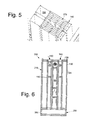
- a further embodiment of a fin structure 270 is shown in Fig. 5 .
- Other components and other configurations also may be used herein.
- the enclosure 100 thus provides a sealed enclosure 200 to protect the electrical components 180 within the interior 190 thereof while being able to accommodate higher internal and ambient temperatures because of the use of the support ducts 140.
- the support ducts 140 act as a heat sink so as to dissipate the heat produced by the electric components 180 via contact with the rail 200 via the ambient airflow 160.
- the duct fans 170 promote the ambient airflow 160 either from the base 110 to the roof 120 or vice versa. Cooling also may be provided by free convection without the use of the duct fans 170. In other words, either forced or natural convection may be used herein.
- the internal fan 220 also circulates internal air about the support ducts 140 and the electrical components 180. The enclosure 100 thus may accommodate higher temperatures without admitting external air and contaminates into the interior 190 of the enclosure 100.
- the enclosure 100 therefore may be used in relatively hot and dusty locations so as to control power plant equipment and the like with less wiring and infrastructure. Moreover, the overall structure of the enclosure 100 may be simplified so as to reduce manufacturing costs. Specifically, the support ducts 140 provide both support and act as a heat sink.
- Fig. 6 shows an alternative embodiment of an enclosure 240.
- the enclosure 240 may be similar to the enclosure 100 described above but without the supports 225 positioned about the base 110.
- a base 250 may be an extended structure with a vent 260 in communication with the air channel 150.
- the base 250 also may have one or more vents 260 thereon for the flow of ambient air 160.
- the vents 260 may be positioned about a sidewall 130 or elsewhere.
- Other components and other configurations may be used herein.
Landscapes
- Engineering & Computer Science (AREA)
- Microelectronics & Electronic Packaging (AREA)
- Physics & Mathematics (AREA)
- Thermal Sciences (AREA)
- Aviation & Aerospace Engineering (AREA)
- Cooling Or The Like Of Electrical Apparatus (AREA)
- Casings For Electric Apparatus (AREA)
Abstract
Description
- The present application and the resultant patent relate generally to enclosures for use with electrical components and more particularly relate to a sealed enclosure with duct mounted electrical components therein and with a cooling flow through the duct.
- Electronic control systems such as power plant control systems and the like generally are densely packed within an enclosure. Such densely packed electrical components may result in relatively high operating temperatures. These high operating temperatures and other thermal considerations may have a bearing on the minimum form factor to which the control systems may be designed, the maximum operating speeds, and the overall performance of the control systems.
- Moreover, industrial control system customers generally intend to place such control systems in locations where ambient temperatures may be high and environmental contaminants such as dust, salt, debris, and the like may be common. The degree of protection provided by any given enclosure thus may be dictated by the area in which the enclosure is to be located. The National Electrical Manufacturers Association ("NEMA") defines different types of enclosures by the location of the enclosure and the various elements that the enclosure must be able to withstand. For example, a fan cooled NEMA 12 enclosure is arranged with filtered inlets and outlets. As such, a certain amount of downtime may be required for the filters to be cleaned periodically. A sealed NEMA 4 enclosure may offer good protection in dusty or wet environments, but such an enclosure may handle less of an internal heat load than a ventilated counterpart. There is thus somewhat of a tradeoff in operational parameters when selecting an enclosure for a particular purpose and location.
- There is thus a desire for an improved enclosure for electrical components and the like. Preferably such an enclosure will be largely sealed to prevent the ingress of containments while being able to operate in temperature ranges typically associated with ventilated enclosures. Moreover, the enclosures should be relatively inexpensive to construct and operate as compared to known enclosures while providing enhanced protection to the electrical components therein.
- The present application and the resultant patent thus provide for an enclosure for mounting electrical components therein. The enclosure may include a base, a roof, a number of side walls, and one or more support ducts extending from the base to the roof. The supports ducts may include an air channel therein extending from the base to the roof.
- The present application and the resultant patent further provide a method of operating electrical components. The method may include the steps of positioning the electrical components about a support duct within an interior of an enclosure, sealing the interior of the enclosure, providing a flow of ambient air through an air channel of the support duct from a base to a roof of the enclosure, and exchanging heat with the electrical components on the support duct and the flow of the ambient air in the air channel.
- The present application and the resultant patent further provide a sealed enclosure for mounting electrical components therein. The sealed enclosure may include a base, a roof, a number of side walls, a number of support ducts extending from the base to the roof, an air channel extending within the supports ducts from the base to the roof, and a duct fan positioned in the air channel of the support ducts.
- These and other features and improvements of the present application and the resultant patent will become apparent to one of ordinary skill in the art upon review of the following detailed description when taken in conjunction with the several drawings and the appended claims.
-
Fig. 1 is a side cross-sectional view of a known enclosure with electrical components therein. -
Fig. 2 is a side cross-sectional view of an enclosure as may be described herein. -
Fig. 3 is a partial perspective view of the enclosure ofFig. 2 with electrical components therein. -
Fig. 4 is a perspective view of a portion of a support duct for use with the enclosure ofFig. 2 . -
Fig. 5 is a perspective view of a portion of an alternative embodiment of a support duct for use with the enclosure ofFig. 2 . -
Fig. 6 is a side cross-sectional view of an alternative embodiment of an enclosure as may be described herein. - Referring now to the drawings, in which like numerals refer to like elements throughout the several views,
Fig. 1 shows a side cross-sectional view of a knownenclosure 10. Generally described, the enclosure includes abase 15, aroof 20, and a number ofsidewall 25. Theoverall enclosure 10 may be of any size, shape, or configuration. Thebase 15, theroof 20, and thesidewall 25 may be made out of a sheet metal or other types of substantially rigid materials intended for use in relatively hostile conditions. - The
enclosure 10 may include a number ofinternal support beams 30 positioned therein. Thesupport beams 30 may have any size, shape, or configuration. Thesupport beams 30 may extend from thebase 15 to theroof 20. Thesupport beams 30 may be made out of steel or other types of substantially rigid materials. Any number of thesupport beams 30 may be used. - A number of
electrical components 35 may be positioned in aninterior 40 of theenclosure 10. Specifically, theelectrical components 35 may be mounted on arail 45. Therail 45 may be positioned about thesupport beams 30. Any number or any type of theelectrical components 35 may be used herein. As described above, theelectrical components 35 tend to generate heat in operation. As such, theelectrical components 35 may have limits on operations above certain ambient or internal temperatures. An access port of some sort may be positioned about theenclosure 10 so as to provide access to theelectrical components 35 within theinterior 40 of theenclosure 10. Although theenclosure 10 shown herein is a sealedenclosure 50, other types of ventilated enclosures also are known. -
Fig. 2 andFig. 3 show an example of anenclosure 100 as may be described herein. Generally described, theenclosure 100 includes a base 110, aroof 120, and a number ofsidewalls 130. Theenclosure 100 and the components thereof may have any size, shape or configuration. The base 110, theroof 120, and thesidewalls 130 may be made out of sheet metal and other substantially rigid materials intended for use in relatively hostile environments. Other components and other configurations may be used herein. - Instead of the
support beams 30 described above, theenclosure 100 may include a number ofsupport ducts 140. Thesupport ducts 140 may define anair channel 150 therein. Thesupport ducts 140 and theair channels 150 may extend from the base 110 to theroof 120 and may be in communication with anambient air flow 160 that may be external to theenclosure 100. Thesupport ducts 140 may be made out of steel or any type of rigid materials sufficient to support theenclosure 100 while also having good heat transfer characteristics. Thesupport ducts 140 and theair channels 150 may have any desired size, shape, or configuration. Any number of thesupport ducts 140 may be used herein. One or more duct fans 170 may be positioned within thesupport ducts 140. The duct fans 170 may be any type of conventional air moving device and the like. Theair channels 150 may be enclosed by ascreen 175 or other structure that prevents debris from passing therethrough without blocking theambient air flow 160. Other components and other configurations may be used herein. - The
enclosure 100 also may have any number ofelectrical components 180 positioned therein. Theelectrical components 180 may include a number of circuit boards, or any type of electrical elements, passive or active. For example, resistors, inductors, capacitors, diodes, transistors, integrated circuits, logic gates, microcontrollers, microprocessors, digital signal processors, floating point gate arrays, memories, static random access memories, dynamic random access memories, read only memories, cable connectors, jumper connectors, or combinations thereof may be used herein. One or more of theelectrical components 180 may dissipate electrical energy and therefore generate heat. Other components and other configurations may be used herein. - The
electrical components 180 may be mounted in an interior 190 of theenclosure 100. Specifically, theelectrical components 180 may be mounted on arail 200, a similar structure, or directly on thesupport ducts 140. Therail 200, in turn, may be mounted on or about thesupport ducts 140. Theelectrical components 180 may be mounted in any conventional manner. Therail 200 likewise may be made out of any substantially rigid material with good heat transfer characteristics. Other components and other configurations also may be used herein. - The
enclosure 100 thus may be a sealedenclosure 210 with respect to the interior 190 while thesupport ducts 140 allow anambient air flow 160 to pass through theair channel 150 so as to provide cooling. One or more interior fans 220 may be mounted within theinterior 190 of theenclosure 100. The interior fans 220 may be any type of air movement device. The base 110 of theenclosure 100 may be raised off of the ground via one ormore supports 225. Thesupports 225 may be rails, feet, or any other structure that is integral or not. An access port of some sort may be positioned about theenclosure 100 so as to provide access to theelectrical components 180 within theinterior 190 of theenclosure 100. Other components and other configurations may be used herein. -
Fig. 4 shows a cross-section of an example of thesupport duct 140. Thesupport duct 140 may include a number of theair channels 150 therein. Moreover, aninternal fin structure 230 also may be used so as to facilitate heat exchange with theambient airflow 160 passing therein. Thefin structure 230 may have any size, shape, or configuration. Differingfin structures 230 may be used. For example, a further embodiment of afin structure 270 is shown inFig. 5 . Other components and other configurations also may be used herein. - The
enclosure 100 thus provides a sealedenclosure 200 to protect theelectrical components 180 within theinterior 190 thereof while being able to accommodate higher internal and ambient temperatures because of the use of thesupport ducts 140. Thesupport ducts 140 act as a heat sink so as to dissipate the heat produced by theelectric components 180 via contact with therail 200 via theambient airflow 160. The duct fans 170 promote theambient airflow 160 either from the base 110 to theroof 120 or vice versa. Cooling also may be provided by free convection without the use of the duct fans 170. In other words, either forced or natural convection may be used herein. The internal fan 220 also circulates internal air about thesupport ducts 140 and theelectrical components 180. Theenclosure 100 thus may accommodate higher temperatures without admitting external air and contaminates into theinterior 190 of theenclosure 100. - The
enclosure 100 therefore may be used in relatively hot and dusty locations so as to control power plant equipment and the like with less wiring and infrastructure. Moreover, the overall structure of theenclosure 100 may be simplified so as to reduce manufacturing costs. Specifically, thesupport ducts 140 provide both support and act as a heat sink. -
Fig. 6 shows an alternative embodiment of an enclosure 240. The enclosure 240 may be similar to theenclosure 100 described above but without thesupports 225 positioned about the base 110. In this example, abase 250 may be an extended structure with avent 260 in communication with theair channel 150. The base 250 also may have one ormore vents 260 thereon for the flow ofambient air 160. Thevents 260 may be positioned about asidewall 130 or elsewhere. Other components and other configurations may be used herein. - It should be apparent that the foregoing relates only to certain embodiments of the present application and the resultant patent. Numerous changes and modifications may be made herein by one of ordinary skill in the art without departing from the general spirit and scope of the invention as defined by the following claims and the equivalents thereof.
- Various aspects and embodiments of the present invention are defined by the following numbered clauses:
- 1. An enclosure for mounting electrical components therein, comprising:
- a base;
- a roof;
- a plurality of side walls; and
- one or more support ducts extending from the base to the roof;
- the one or more supports ducts comprising an air channel therein extending from the base to the roof.
- 2. The enclosure of clause 1, wherein the one or more support ducts comprise a duct fan about the air channel.
- 3. The enclosure of any preceding clause, wherein the base, the roof, and the plurality of sidewalls define an interior with the electrical components therein and wherein the enclosure comprises a sealed enclosure.
- 4. The enclosure of any preceding clause, further comprising a rail positioned on the one or more support ducts and with the electrical components mounted thereon.
- 5. The enclosure of any preceding clause, wherein the rail comprises a thermally conductive material.
- 6. The enclosure of any preceding clause, wherein the one or more support ducts comprise a thermally conductive material.
- 7. The enclosure of any preceding clause, wherein the one or more support ducts comprise a plurality of fins positioned within the air channel.
- 8. The enclosure of any preceding clause, further comprising an interior fan.
- 9. The enclosure of any preceding clause, wherein the one or more support ducts comprise a pair of support ducts.
- 10. The enclosure of any preceding clause, wherein the base comprises a vent in communication with the air channel.
- 11. The enclosure of any preceding clause, wherein the vent is positioned about one or more of the plurality of sidewalls.
- 12. The enclosure of any preceding clause, wherein the base comprises one or more supports.
- 13. The enclosure of any preceding clause, wherein the air channel comprises a screen positioned about the base and/or the roof.
- 14. A method of operating electrical components, comprising:
- positioning the electrical components about a support duct within an interior of an enclosure;
- sealing the interior of the enclosure;
- providing a flow of ambient air through an air channel of the support duct from a base to a roof of the enclosure; and
- exchanging heat with the electrical components on the support duct and the flow of ambient air in the air channel.
- 15. A sealed enclosure for mounting electrical components therein, comprising:
- a base;
- a roof;
- a plurality of side walls;
- a plurality of support ducts extending from the base to the roof;
- the plurality of supports ducts comprising an air channel therein extending from the base to the roof; and
- a duct fan positioned in the air channel of the plurality of support ducts.
- 16. The sealed enclosure of any preceding clause, further comprising a rail positioned on one or more of the plurality of support ducts and with the electrical components mounted thereon.
- 17. The sealed enclosure of any preceding clause, wherein the rail and the plurality of support ducts comprise a thermally conductive material.
- 18. The sealed enclosure of any preceding clause, wherein the plurality of support ducts comprises a plurality of fins positioned within the air channel.
- 19. The sealed enclosure of any preceding clause, further comprising an interior fan positioned about the plurality of support ducts.
- 20. The sealed enclosure of any preceding clause, wherein the air channel comprises a screen positioned about the base and/or the roof.
Claims (15)
- An enclosure (100) for mounting electrical components (180) therein, comprising:a base (110);a roof (120);a plurality of side walls (130); andone or more support ducts (140) extending from the base (110) to the roof (120);the one or more supports ducts (140) comprising an air channel (150) therein extending from the base (110) to the roof (120).
- The enclosure of claim 1, wherein the one or more support ducts (140) comprise a duct fan (170) about the air channel (150).
- The enclosure of claim 1 or claim 2, wherein the base (110), the roof (120), and the plurality of sidewalls (130) define an interior (190) with the electrical components therein and wherein the enclosure (100) comprises a sealed enclosure.
- The enclosure of claim 1, 2 or 3, further comprising a rail (200) positioned on the one or more support ducts (140) and with the electrical components (180) mounted thereon.
- The enclosure of claim 4, wherein the rail (200) comprises a thermally conductive material.
- The enclosure of any preceding claim, wherein the one or more support ducts (140) comprise a thermally conductive material.
- The enclosure of any preceding claim, wherein the one or more support ducts (140) comprise a plurality of fins positioned within the air channel (150).
- The enclosure of any preceding claim, further comprising an interior fan (220).
- The enclosure of any preceding claim, wherein the one or more support ducts (140) comprise a pair of support ducts.
- The enclosure of any preceding claim, wherein the base (110) comprises a vent (260) in communication with the air channel (150).
- The enclosure of claim 10, wherein the vent (260) is positioned about one or more of the plurality of sidewalls (130).
- The enclosure of claim 10 or claim 11, wherein the base (110) comprises one or more supports.
- The enclosure of any preceding claim, wherein the air channel (150) comprises a screen positioned about the base and/or the roof.
- A method of operating electrical components (180), comprising:positioning the electrical components (180) about a support duct (140) within an interior of an enclosure (100);sealing the interior of the enclosure (100);providing a flow of ambient air through an air channel (150) of the support duct (140) from a base (110) to a roof (120) of the enclosure; andexchanging heat with the electrical components (180) on the support duct (140) and the flow of ambient air in the air channel (150).
- A sealed enclosure for mounting electrical components therein, comprising the enclosure of any preceding claim, comprising:a plurality of support ducts (140) extending from the base (110) to the roof (120), the plurality of supports ducts comprising an air channel (150) therein extending from the base to the roof; anda duct fan (170) positioned in the air channel (150) of the plurality of support ducts (140).
Applications Claiming Priority (1)
| Application Number | Priority Date | Filing Date | Title |
|---|---|---|---|
| US13/460,967 US8687363B2 (en) | 2012-05-01 | 2012-05-01 | Enclosure with duct mounted electronic components |
Publications (2)
| Publication Number | Publication Date |
|---|---|
| EP2661166A2 true EP2661166A2 (en) | 2013-11-06 |
| EP2661166A3 EP2661166A3 (en) | 2014-06-11 |
Family
ID=48184100
Family Applications (1)
| Application Number | Title | Priority Date | Filing Date |
|---|---|---|---|
| EP13166106.8A Withdrawn EP2661166A3 (en) | 2012-05-01 | 2013-05-01 | Enclosure with duct mounted electronic components |
Country Status (3)
| Country | Link |
|---|---|
| US (1) | US8687363B2 (en) |
| EP (1) | EP2661166A3 (en) |
| CN (1) | CN103384461B (en) |
Cited By (1)
| Publication number | Priority date | Publication date | Assignee | Title |
|---|---|---|---|---|
| EP2938173A1 (en) * | 2014-04-25 | 2015-10-28 | Alcatel Lucent | Electronics enclosure cooling |
Families Citing this family (4)
| Publication number | Priority date | Publication date | Assignee | Title |
|---|---|---|---|---|
| US9218028B2 (en) | 2013-06-07 | 2015-12-22 | Apple Inc. | Computer housing |
| US11899509B2 (en) | 2013-06-07 | 2024-02-13 | Apple Inc. | Computer housing |
| CN104456763A (en) * | 2014-10-31 | 2015-03-25 | 华为技术有限公司 | Heat radiation structure of air conditioner outdoor unit fan driver and air conditioner outdoor unit |
| CN113875326B (en) * | 2019-05-29 | 2025-01-21 | 汤姆逊许可公司 | Device for thermal management in electronic equipment |
Family Cites Families (21)
| Publication number | Priority date | Publication date | Assignee | Title |
|---|---|---|---|---|
| US3961666A (en) * | 1972-11-24 | 1976-06-08 | Sony Corporation | Heat dispersion device for use in an electronic apparatus |
| DE2710432C3 (en) * | 1977-03-10 | 1980-01-17 | Danfoss A/S, Nordborg (Daenemark) | Housing for an electrical circuit arrangement |
| US4535386A (en) * | 1983-05-23 | 1985-08-13 | Allen-Bradley Company | Natural convection cooling system for electronic components |
| JPH0719991B2 (en) * | 1990-02-28 | 1995-03-06 | 三菱電機株式会社 | Controller case |
| US5218516A (en) * | 1991-10-31 | 1993-06-08 | Northern Telecom Limited | Electronic module |
| US5398159A (en) * | 1992-12-15 | 1995-03-14 | Telefonaktiebolaget Lm Ericsson | Modular packaging system |
| US5712107A (en) * | 1995-06-07 | 1998-01-27 | Pioneer Hi-Bred International, Inc. | Substitutes for modified starch and latexes in paper manufacture |
| US5777846A (en) * | 1996-05-30 | 1998-07-07 | Northern Telecom Limited | Circuit packs and circuit pack and shelf assemblies |
| JPH11261265A (en) * | 1998-03-12 | 1999-09-24 | Nec Corp | Radiation structure of sealed device |
| US6127663A (en) * | 1998-10-09 | 2000-10-03 | Ericsson Inc. | Electronics cabinet cooling system |
| US6365826B1 (en) | 1999-12-22 | 2002-04-02 | General Electric Company | Waterproof enclosure for electrical devices |
| US6504714B1 (en) * | 2000-08-16 | 2003-01-07 | Square D Company | Multi-level thermal management system and method |
| US6459577B1 (en) * | 2001-07-06 | 2002-10-01 | Apple Computer, Inc. | Thermal chimney for a computer |
| US7038910B1 (en) * | 2002-01-07 | 2006-05-02 | Wave7 Optics, Inc. | System and method for removing heat from a subscriber optical interface |
| JP2004200594A (en) * | 2002-12-20 | 2004-07-15 | Agilent Technol Inc | System rack with exhaust structure |
| US7064647B2 (en) | 2004-06-22 | 2006-06-20 | General Electric Company | Fabricated air core reactor |
| US7804685B2 (en) * | 2005-09-19 | 2010-09-28 | Chatsworth Products, Inc. | Ducted exhaust equipment enclosure |
| US20080278912A1 (en) * | 2007-05-09 | 2008-11-13 | Dean Zavadsky | Thermal management systems and methods for electronic components in a sealed enclosure |
| ATE518183T1 (en) * | 2007-09-07 | 2011-08-15 | Kontron Ag | PASSIVE COOLED COMPUTER |
| FR2926399B1 (en) * | 2008-01-16 | 2010-02-05 | Intelligent Electronic Systems | MULTI-POSITION METALLIC EXTRUDED PROFILE HOUSING FOR MANUFACTURING AN ELECTRONIC DEVICE FOR SEALED POWER |
| US8011951B2 (en) | 2009-06-23 | 2011-09-06 | General Electric Company | Rail mounting apparatus |
-
2012
- 2012-05-01 US US13/460,967 patent/US8687363B2/en not_active Expired - Fee Related
-
2013
- 2013-05-01 EP EP13166106.8A patent/EP2661166A3/en not_active Withdrawn
- 2013-05-02 CN CN201310158204.3A patent/CN103384461B/en not_active Expired - Fee Related
Non-Patent Citations (1)
| Title |
|---|
| None |
Cited By (1)
| Publication number | Priority date | Publication date | Assignee | Title |
|---|---|---|---|---|
| EP2938173A1 (en) * | 2014-04-25 | 2015-10-28 | Alcatel Lucent | Electronics enclosure cooling |
Also Published As
| Publication number | Publication date |
|---|---|
| US20130292095A1 (en) | 2013-11-07 |
| EP2661166A3 (en) | 2014-06-11 |
| CN103384461B (en) | 2017-08-01 |
| CN103384461A (en) | 2013-11-06 |
| US8687363B2 (en) | 2014-04-01 |
Similar Documents
| Publication | Publication Date | Title |
|---|---|---|
| US10575433B2 (en) | Enclosure and cooling system for electronic equipment | |
| US8611088B2 (en) | Mechanical heat pump for an electrical housing | |
| US20080278912A1 (en) | Thermal management systems and methods for electronic components in a sealed enclosure | |
| US8687363B2 (en) | Enclosure with duct mounted electronic components | |
| US8462504B2 (en) | Air-cooled heat exchanger and electronic device with same | |
| US9414524B2 (en) | Extended heat frame for printed circuit board | |
| US7031158B2 (en) | Heat pipe cooled electronics enclosure | |
| US10028414B2 (en) | Passive cooling features for electronics equipment cabinets | |
| KR101479897B1 (en) | Electronic apparatus | |
| US20110198062A1 (en) | Cooler arrangement for an electrical or equipment cabinet having air-to-air heat exchanger cassettes | |
| KR101360730B1 (en) | Cooling device and electronic device thereof | |
| CN109690763B (en) | Switch cabinet with closed shell and cooling device | |
| JP2011138960A (en) | Power converter for vehicle | |
| US10939586B2 (en) | Heat exchanger structure for a rack assembly | |
| JP2012164743A (en) | On-vehicle electronic apparatus | |
| CN102469742A (en) | Electronic device | |
| JP2008010820A (en) | Heat sink and base station apparatus | |
| CN202873253U (en) | Anti-pollution device | |
| CN101970735A (en) | Device having cooled power unit for the production of fancy yarn | |
| KR100713080B1 (en) | A communication machinery and tools repeater which the prosecution heroine is separated | |
| JP7442542B2 (en) | power converter | |
| KR200369177Y1 (en) | Rack for communication device | |
| CN119653722A (en) | A communication cabinet | |
| KR102545308B1 (en) | Apparatus for removing dew of electronic device | |
| KR200342996Y1 (en) | Telecomunication system box that have radiating structure |
Legal Events
| Date | Code | Title | Description |
|---|---|---|---|
| PUAI | Public reference made under article 153(3) epc to a published international application that has entered the european phase |
Free format text: ORIGINAL CODE: 0009012 |
|
| AK | Designated contracting states |
Kind code of ref document: A2 Designated state(s): AL AT BE BG CH CY CZ DE DK EE ES FI FR GB GR HR HU IE IS IT LI LT LU LV MC MK MT NL NO PL PT RO RS SE SI SK SM TR |
|
| AX | Request for extension of the european patent |
Extension state: BA ME |
|
| PUAL | Search report despatched |
Free format text: ORIGINAL CODE: 0009013 |
|
| RIC1 | Information provided on ipc code assigned before grant |
Ipc: H05K 7/20 20060101AFI20140430BHEP |
|
| AK | Designated contracting states |
Kind code of ref document: A3 Designated state(s): AL AT BE BG CH CY CZ DE DK EE ES FI FR GB GR HR HU IE IS IT LI LT LU LV MC MK MT NL NO PL PT RO RS SE SI SK SM TR |
|
| AX | Request for extension of the european patent |
Extension state: BA ME |
|
| 17P | Request for examination filed |
Effective date: 20141211 |
|
| RBV | Designated contracting states (corrected) |
Designated state(s): AL AT BE BG CH CY CZ DE DK EE ES FI FR GB GR HR HU IE IS IT LI LT LU LV MC MK MT NL NO PL PT RO RS SE SI SK SM TR |
|
| GRAP | Despatch of communication of intention to grant a patent |
Free format text: ORIGINAL CODE: EPIDOSNIGR1 |
|
| INTG | Intention to grant announced |
Effective date: 20170616 |
|
| STAA | Information on the status of an ep patent application or granted ep patent |
Free format text: STATUS: THE APPLICATION IS DEEMED TO BE WITHDRAWN |
|
| 18D | Application deemed to be withdrawn |
Effective date: 20171027 |