EP2661017A1 - System and method for automated trap configuration in network management systems - Google Patents
System and method for automated trap configuration in network management systems Download PDFInfo
- Publication number
- EP2661017A1 EP2661017A1 EP12166752.1A EP12166752A EP2661017A1 EP 2661017 A1 EP2661017 A1 EP 2661017A1 EP 12166752 A EP12166752 A EP 12166752A EP 2661017 A1 EP2661017 A1 EP 2661017A1
- Authority
- EP
- European Patent Office
- Prior art keywords
- trap
- status
- validation
- managing device
- managed
- Prior art date
- Legal status (The legal status is an assumption and is not a legal conclusion. Google has not performed a legal analysis and makes no representation as to the accuracy of the status listed.)
- Granted
Links
Images



Classifications
-
- H—ELECTRICITY
- H04—ELECTRIC COMMUNICATION TECHNIQUE
- H04L—TRANSMISSION OF DIGITAL INFORMATION, e.g. TELEGRAPHIC COMMUNICATION
- H04L41/00—Arrangements for maintenance, administration or management of data switching networks, e.g. of packet switching networks
- H04L41/06—Management of faults, events, alarms or notifications
- H04L41/0686—Additional information in the notification, e.g. enhancement of specific meta-data
-
- H—ELECTRICITY
- H04—ELECTRIC COMMUNICATION TECHNIQUE
- H04L—TRANSMISSION OF DIGITAL INFORMATION, e.g. TELEGRAPHIC COMMUNICATION
- H04L41/00—Arrangements for maintenance, administration or management of data switching networks, e.g. of packet switching networks
- H04L41/08—Configuration management of networks or network elements
- H04L41/0803—Configuration setting
- H04L41/0813—Configuration setting characterised by the conditions triggering a change of settings
- H04L41/082—Configuration setting characterised by the conditions triggering a change of settings the condition being updates or upgrades of network functionality
Definitions
- the present invention relates generally to network management systems.
- the present invention relates to automated trap configuration in network management systems.
- Network management systems are commonly implemented for configuring, monitoring and managing network devices coupled to a communication network.
- at least one management station is configured to communicate and manage multiple network devices, such as switches, routers, microwave radios, printers, workstations, programmable logic controllers, communication processors, and so on.
- Each network device is provided with an agent module that locally monitors and stores operational and event data related to the network device.
- the management station includes a management module which requests operational and event data and/or receives unsolicited notifications from the agent module using standard communication protocols.
- SNMP Simple Network Management Protocol
- MIB Management Information Base
- MIB specifies information that a network device should provide to the management station. All data referring to managed features of the network device are referred to as objects, which are represented by MIB variables which can be queried or modified. MIB uses a hierarchical namespace such that each object is assigned a unique object identifier (OID). Each OID identifies an object that can be read or set via SNMP.
- OID object identifier
- SNMP is based on a read-write paradigm to effect control and management operations.
- SNMP defines four basic commands, namely get-request, get-next-request, get-response, and set-request to enable basic read and write operations.
- SNMP defines a trap command, which enables an agent to asynchronously send event notifications to the management module.
- the agent module In order to enable the agent module to send a trap to the management module, the agent module is required to be configured with trap destination information.
- the trap destination information includes, for example, an IP address/hostname of the management station, management port and management community.
- each network device must be manually configured with trap destination information.
- trap destination information typically, there are several tens or a few hundred agents that are managed by a management station. It is a tedious task to manually configure each agent for trap information, especially when a new management station comes in, or the IP address and/or port and/or community string of an existing management station changes.
- the trap destination information when relevant settings on the management station are changed or the management station is altogether replaced, the trap destination information must be manually reconfigured in each network device.
- a network administrator has to manually configure IP address and/or port and/or community string one by one in agent modules of each network device using a web interface or any other suitable configuration tool.
- the improved system and method should eliminate manual effort required for configuring trap information in individual network devices in various network management systems.
- an object of the present invention is to provide a system and a method for automated trap configuration in multiple network devices in a network management system.
- the object of the present invention is achieved by a method for automated trap configuration in a network management system according to claim 1, and a system and a computer program product therefor according to claim 6 and claim 11 respectively. Further embodiments of the present invention are addressed in the dependent claims.
- a method for automated trap configuration in a network management system comprises at least one managing device and one or more managed devices. Each managed device is configurable for sending a trap message to the at least one managing device.
- a trap configuration object is retrieved from at least one managed device.
- the trap configuration object is parsed to determine availability of trap destination information corresponding to the managing device.
- the trap destination information corresponds to one or more network parameters of the managing device.
- one or more configuration instructions from the managing device are transmitted to the at least one managed device based on availability of the trap destination information.
- the configuration instructions are such that the trap configuration object is processed such as to include the trap destination information corresponding to the managing device.
- the at least one managed device is configured to send a trap message to the managing device.
- the present invention provides a method for automated trap configuration in individual network devices in a network management system.
- the technique of the present invention entirely eliminates any manual intervention in trap configuration in the network management system. Therefore, the techniques of the present invention facilitate reducing time and effort required in trap configuration while implementing any changes in the network management system.
- the present invention advantageously renders the network management system more flexible and conducive to systemic changes and restructuring.
- a trap validation list is maintained in each managing device.
- the trap validation list comprises information related to the one or more managed devices along with a corresponding trap validation status.
- the trap validation status is set to a first status to indicate that corresponding managed device is to be configured to send a trap message to the managing device.
- the trap validation status is set to a second status to indicate that corresponding managed device is configured to send a trap message to the managing device.
- At least one managed device is discovered, information related to the at least one managed device is appended to the trap validation list, and trap validation status corresponding to the at least one managed device is set to the first status.
- each new managed device which is detected through an auto-discovery process is advantageously included in the trap validation list.
- the trap validation status of such managed device is set to the first status such that subsequently, the managing device initiates automated trap configuration therefor.
- one or more network parameters of the managing device are monitored, and the trap validation status is changed from the second status to the first status for each managed device in the trap validation list subsequent to an alteration of such network parameters of the managing device that are related to the trap destination information.
- the managing device subsequent to any changes in network parameters thereof, advantageously re-initiates automated trap configuration, as per the various techniques of the present invention, for each managed device.
- the first, second, and third steps, as described above, are performed for each managed device for which the trap validation status in the trap validation list is set to the first status. Subsequent to performing these steps for the managed device, and confirming that the trap configuration object in said managed device is successfully processed, corresponding trap validation status in the trap validation list is set to the second status.
- This technical feature advantageously enables the managing device to systematically keep a record of all managed devices which are successfully configured for sending trap messages thereto.
- a network management system adapted for automated trap configuration in a network management system.
- the network management system comprises at least one managing device and one or more managed devices. Each managed device is configurable for sending a trap message to said at least one managing device.
- the managing device comprises a retrieving module, a processing module, and a transmitting module.
- the retrieving module is configured for retrieving a trap configuration object from at least one managed device.
- the processing module is configured for parsing the trap configuration object to determine availability of trap destination information corresponding to the managing device.
- the trap destination information corresponds to one or more network parameters of the managing device.
- the processing module is further configured for generating one or more configuration instructions based on availability of the trap destination information.
- the transmitting module is configured for transmitting the configuration instructions to the at least one managed device.
- the configuration instructions are such that the trap configuration object is processed such as to include the trap destination information corresponding to the managing device.
- the at least one managed device is configured to send a trap message to the managing device.
- the present invention provides a network management system adapted for automated trap configuration in individual network devices.
- the technique of the present invention entirely eliminates any manual intervention in trap configuration in the network management system. Therefore, the techniques of the present invention are facilitates reducing time and effort required towards trap configuration while implementing any changes in the network management system.
- the present invention advantageously renders the network management system more flexible and conducive to systemic changes and restructuring.
- each managing device comprises a trap validation list.
- the trap validation list comprises information related to the one or more managed devices along with a corresponding trap validation status.
- the trap validation status is set to a first status to indicate that corresponding managed device is to be configured to send a trap message to the managing device.
- the trap validation status is set to a second status to indicate that corresponding managed device is configured to send a trap message to the managing device.
- the network management system comprises a discovery module.
- the discovery module is configured for discovering at least one managed device, appending information related to the at least one managed device to the trap validation list, and setting trap validation status corresponding to the at least one managed device to the first status.
- each new managed device which is detected through an auto-discovery process is advantageously included in the trap validation list.
- the trap validation status of such managed device is set to the first status such that subsequently, the managing device initiates automated trap configuration therefor.
- the network management system comprises a reconfiguring module.
- the reconfiguring module is configured for monitoring one or more network parameters of the managing device, and changing the trap validation status for each managed device in the trap validation list from the second status to the first status subsequent to an alteration of such network parameters of the managing device that are related to the trap destination information.
- the managing device subsequent to any changes in network parameters thereof, advantageously re-initiates automated trap configuration, as per the various techniques of the present invention, for each managed device.
- the retrieving module successively retrieves the trap configuration object for each managed device for which the trap validation status in the trap validation list is set to the first status, further wherein subsequent to transmitting the configuration instructions to the managed device, and confirming that the trap configuration object in the at least one managed device is successfully configured, the processing module sets the corresponding trap validation status in the trap validation list to the second status.
- a computer program product for automated trap configuration in a network management system is provided.
- the computer program product is embodied on a computer readable medium.
- the computer-readable medium comprises computer-executable instructions for automated trap configuration in the network management system.
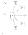
- FIG 1 illustrates a schematic representation of a network management system 100 in accordance with an embodiment of the present invention.
- the network management system 100 includes a managing device 102 and multiple managed devices 104a through 104n (hereinafter collectively referred to as managed devices 104 and individually referred to as managed device 104).
- the managing device 102 and the managed devices 104 are communicatively coupled to a communication network 106.
- the managing device 102 is implemented as a dedicated computer workstation which realizes a management module (not shown).
- the managing device 102 through the management module, configures and monitors the managed devices 104. It should be noted that although the adjoining figure depicted only one managing device 102, multiple managing devices 102 may be implemented in a similar manner.
- managed devices 104 include, but are not limited, switches, routers, microwave radios, printers, workstations, and so on.
- Each managed devices 104 realizes an agent module (not shown) that locally monitors and stores operational and event data related to the managed devices 104.
- the communication network 106 is based on any suitable network architecture including, but not limited to, Local Area Network (LAN), Metropolitan Area Network (MAN), and Wide Area Network (WAN).
- LAN Local Area Network
- MAN Metropolitan Area Network
- WAN Wide Area Network
- SNMP Simple Network Management Protocol
- Each managed device 104 maintains a virtual data store, referred to as a management information base (MIB), which stores all data related to managed features of the managed device 104 as individual objects, wherein each object is assigned a unique object identifier (OID).
- MIB management information base
- OID unique object identifier
- the managing device 102 is capable of reading data values stored in individual objects and also, writing desired data values to individual objects stored in the managed devices 104.
- the managed devices 104 are capable to sending unsolicited notifications to the managing device 102. Such unsolicited notification is referred to as a trap message.
- the managed device 104 requires trap destination information corresponding to one or more network parameters related to managing device 102.
- these network parameters include IP address/hostname, port, and community.
- Each managed devices 104 stores the trap destination information in a trap configuration object within the management information base. The trap configuration object is explained in conjunction with FIG 2 below.
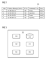
- the trap configuration object 200 includes trap destination information required to send a trap message from the managed device 104 to managing device 102.
- the trap configuration object 200 is in tabular format.
- the trap configuration object 200 includes columnar variables such as 'Index', 'IP address/hostname', 'Port', 'Community', and 'Status'.
- the columnar variable 'Index' is used to uniquely address an individual row/entry in the trap configuration object 200.
- the columnar variable 'Status' is in accordance with SNMP specification and is required for managing individual rows/entries in the trap configuration object 200.
- the remaining columnar variables 'IP address/hostname'; 'Port'; and 'Community' provide the required trap destination information such that a trap message may be appropriately configured such as to reach the managing device 102.
- the trap destination information may correspond to additional or less network parameters corresponding to the managing device 102.
- each row/entry in the trap configuration object 200 corresponds to an individual managing device 102.
- the trap configuration object 200 has been depicted as a tabular object only by way of example.
- the trap configuration object 200 may be implemented using any suitable data structure already known in the art or as may be developed in future.
- different managed devices 104 implement the trap configuration object 200 using different data structures.
- the values depicted in FIG 2 are for exemplary purpose only and should not be construed to limit the present invention in any manner whatsoever.
- the managed device 104 looks up the trap configuration object 200 and prepares a trap messages for each managing device 102 for which the trap destination information is included in the trap configuration object 200.
- FIG 3 a schematic representation of the managing device 102 is illustrated in accordance with an embodiment of the present invention.
- the managing device 102 includes a retrieving module 302, a processing module 304, and a transmitting module 306.
- the managing device 102 includes a discovery module 308, a reconfiguring module 310, and a memory module 312.
- the retrieving module 302 is configured for retrieving the trap configuration object 200 from each managed device 104.
- the processing module 304 is configured for parsing the trap configuration object 200 to determine availability of trap destination information corresponding to the managing device 102. As explained earlier, the trap destination information corresponds to one or more network parameters of the managing device 102.
- the processing module 304 is also configured for generating one or more configuration instructions based on availability of the trap destination information in the trap configuration object 200, that is, the processing module 304 generates appropriate configuration instructions in case the desired trap destination information corresponding to the managing device 102 is not available in the trap configuration object 200.
- the transmitting module 306 is configured for transmitting the configuration instructions to the managed device 104.
- the trap configuration object 200 is processed in accordance with the configuration instructions such that the trap configuration object 200 includes the trap destination information corresponding to the managing device 102.
- the managed device 104 is configured to send a trap message to the managing device 102.
- the memory module 312 stores a trap validation list.
- An exemplary trap validation list 400 is shown in FIG 4 .
- the trap validation list 400 is in a tabular format and includes columnar variables 'Index', 'IP address/hostname', and 'Trap Validation Status'.
- the trap validation list 400 includes information related to the managed devices 104 along with a corresponding trap validation status.
- the trap validation status is set to a first status, for example "void", to indicate that corresponding managed device 104 is to be configured to send a trap message to the managing device 102.
- the trap validation status is set to a second status, for example "configured”, to indicate that corresponding managed device 104 is configured to send a trap message to the managing device 102.
- additional trap validation status may be defined to indicate additional status of the managed devices 104.
- the trap validation status corresponding to those managed devices 104 may be set to a third status, for example "Ignore", such that these are no longer considered for automated trap configuration procedure.
- the trap validation list 400 may be implemented using any suitable data structure known in the art or as may be developed in future. Further, the values depicted in FIG 4 are for exemplary purpose only and should not be construed to limit the present invention in any manner whatsoever.
- the discovery module 308 is configured for discovering one or more managed devices 104.
- any suitable auto-discovery technique may be used.
- the present invention uses a trap-based auto-discovery technique in addition to a more general auto-discovery technique.
- various auto-discovery techniques are well-known in the art and are not being described herein for the sake of brevity.
- the discovery module 308 appends corresponding information to the trap validation list 400.
- the corresponding trap validation status is set to the first status ("void") to indicate that the corresponding managed device 104 is to be configured for trap information.
- the reconfiguring module 310 is configured for monitoring one or more network parameters of the managing device, and changing the trap validation status for each managed device 104 in the second status in the trap validation list 400 from the second status to the first status subsequent to an alteration of such one or more network parameters of the managing device 102 that are related to the trap destination information.
- the processing module 304 monitors the trap validation list 400. When one or more managed devices 104 are set to the first status "void". The processing module 304 triggers an automated trap configuration procedure in accordance with techniques of the present invention.
- the retrieving module 302 successively retrieves the trap configuration object 200 for each managed device 104 for which the trap validation status in the trap validation list 400 is set to the first status ("void").
- the processing module 304 parses the trap configuration object 200 and generates appropriate configuration instructions. It should be noted that in case the trap destination information corresponding to the managing device 102 is already included in the trap configuration object 200, the managing device 102 does not send any configuration instructions to the managed device 104. However, the processing module 304 updates the trap validation list 400 in the memory module 312 such that the trap validation status corresponding to the managed device 104 is updated to the second status ("configured").
- the transmitting module 306 transmits the configuration instructions to the managed device 104.
- the managed device 104 suitably processes the trap configuration object 200 in accordance with the configuration instructions.
- the managing device 102 confirms that the managed device 104 has successfully processed the trap configuration object 200 therein.
- network management system 100 The operation of network management system 100 will now be explained in more detail with reference to FIGS 3 and 5 .
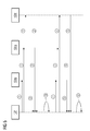
- FIG 5 illustrates a sequence diagram for automated trap configuration in accordance with an embodiment of the present invention.
- the automated trap configuration procedure of the present invention is triggered based on presence of one or more managed device 104 in the trap validation list 400 with the trap validation status as the first status ("void").
- the managed devices 104 are set to the first status under two conditions viz. firstly, when the managed device 104 is newly discovered by the managing device 102, and secondly, when one or more network parameters of managing device 102 are changed and reconfiguring module 310 acts to change trap validation status from the second status to the first status for each managed device 104 in the trap validation list 400.
- the processing module 304 then triggers the automated trap configuration procedure, which is best shown in FIG 5 .
- the managing device 102 sends a GET / GET-BULK message to the managed device 104 to retrieve the trap configuration object 200.
- each managed device 104 responds with GET-RESPONSE message and provides the corresponding trap configuration object 200 to the managing device 102.
- the trap configuration object 200 in the managed device 104 is locked for access by any other managing device 102 to ensure data integrity and prevent data loss due to simultaneous access.
- the managing device 102 more specifically, the processing module 304 parses the trap configuration object 200.
- the processing module 304 updates the trap validation list 400 in the memory module 312 such that the trap validation status corresponding to the managed device 104 is updated to the second status ("configured").
- Step 4 is performed.
- the processing module 304 generates a set of configuration instructions, to create an additional row/entry in the trap configuration object 200 stored in the managed device 104 and set the attributes according to the one or more network parameters of the managing device 102.
- the techniques for appending additional row in a tabular object are well-known in the art and hence, are not being described here in detail.
- the processing module 304 selects the most optimum value for the network attribute based on a suitable algorithm. For example, in case the managing device 102 includes multiple network-interface cards (NIC), the managing device 102 is addressable using multiple IP addresses. In this case, the processing module 304 selects the IP address which provides the most optimum routing path based on the IP address of the managed device 104.
- NIC network-interface cards
- the managed device 104 provides a confirmation message to the managing device 102 to confirm that the trap configuration object 200 has been suitably modified to include trap destination information corresponding to the managing device 102.
- a positive confirmation is possible through an additional GET message to verify that desired trap destination information has been included in the trap configuration object 200.
- the managing device 102 implicitly confirms that the trap configuration object 200 has been successfully processed.
- the processing module 304 accordingly updates the trap validation status corresponding to the managed device 104 in the trap validation list 400 to the second status ("configured").
- the reconfiguring module 310 changes the trap validation status for each managed device 104 in the trap validation list 400 from the second status to the first status.
- the processing module 304 then triggers the automated trap configuration in a similar manner as described above.
- the corresponding set of interactions between the managing device 102 and the managed devices 104 same as those shown in FIG 5 .
- the trap validation status corresponding to those managed devices 104 may be set to the third status ("Ignore"), such that these managed devices 104 are no longer considered for automated trap configuration procedure.
- the processing module 304 sets the trap validation status to the third status ("Ignore"), in parallel, it generates appropriate configuration instructions and provides to the transmitting module 306.
- the transmitting module 306, transmits the configuration instructions to the managed device 104.
- the configuration instructions are such that the trap configuration object 200 is modified in such manner as to remove an entry/row corresponding to the managing device 102 from the trap configuration object 200.
- FIG 6 illustrates a basic flowchart depicting a method for automated trap configuration in a network management system in accordance with an embodiment of the present invention.
- the network management system includes at least one managing device and one or more managed devices. Each managed device is configurable for sending a trap message to the at least one managing device.
- a trap configuration object is retrieved from at least one managed device.
- the trap configuration object includes trap destination information corresponding to one or more network parameters related to the managing device.
- the trap configuration object is parsed to determine availability of trap destination information corresponding to the managing device.
- the trap destination information corresponds to one or more network parameters of the managing device.
- one or more configuration instructions from the managing device are transmitted to the at least one managed device based on availability of the trap destination information.
- the configuration instructions are such that the trap configuration object is processed such as to include the trap destination information corresponding to the managing device.
- the trap configuration object already includes the trap destination information corresponding to the managing device, no configuration instructions are sent to the managed device. Otherwise, the configuration instructions ensure that the trap configuration object is appropriately modified to include the trap destination information corresponding to the managing device.
- the at least one managed device is configured to send a trap message to the managing device.
- FIG 7 illustrates a detailed flowchart depicting a method for automated trap configuration in a network management system in accordance with an embodiment of the present invention.
- each managing device maintains a trap validation list.
- the trap validation list includes a list of one or more managed devices along with a corresponding trap validation status.
- the trap validation status is set to a first status such as "void” to indicate that corresponding managed device is to be configured to send a trap message to the managing device.
- the trap validation status is set to a second status such as "configured” to indicate that corresponding managed device is configured to send a trap message to the managing device.
- the managing device initiates automated trap configuration for all such managed devices that are set to the first status ("void").
- At step 702 at least one managed device is discovered. Subsequently, at step 706, the information related to the managed device is appended to the trap validation list, and the corresponding trap validation status is set to the first status.
- each new managed device which is detected through an auto-discovery process is advantageously included in the trap validation list.
- the trap validation status of such managed device is set to the first status such that subsequently, the managing device initiates automated trap configuration therefor.
- one or more network parameters corresponding to the managing device are monitored. Subsequently, at step 706, the trap validation status for each managed device which is in the second status, the trap validation status is changed from the second status to the first status in the trap validation list subsequent to an alteration of such network parameters of the managing device that are related to the trap destination information.
- the managing device advantageously re-initiates automated trap configuration for each managed device.
- the trap validation list is monitored for any changes. In case the trap validation list is changed at step 706, at step 710, the automated trap configuration procedure is initiated.
- the steps 712 through 716 are performed.
- the steps 712 through 716 are same as steps 602 through 606 respectively described in conjunction with the preceding figure.
- the managing device confirms that the trap configuration object in the managed device includes trap destination information corresponding to the managing device. Accordingly, the corresponding trap validation status in the trap validation list is set to the second status.
- the present invention provides a technique for automated trap configuration in individual network devices in a network management system.
- the technique of the present invention entirely eliminates any manual intervention in trap configuration in the network management system. Therefore, the techniques of the present invention are facilitates reducing time and effort required towards trap configuration while implementing any changes in the network management system.
- the present invention advantageously renders the network management system more flexible and conducive to systemic changes and restructuring.
- the present invention can take the form of a computer program product comprising program modules accessible from computer-usable or computer-readable medium storing program code for use by or in connection with one or more computers, processors, or instruction execution system.
- a computer-usable or computer readable medium can be any apparatus that can contain, store, communicate, propagate, or transport the program for use by or in connection with the instruction execution system, apparatus, or device.
- the medium can be an electronic, magnetic, optical, electromagnetic, infrared, or semiconductor system (or apparatus or device) or a propagation medium (though propagation mediums in and of themselves as signal carriers are not included in the definition of physical computer-readable medium).
- Examples of a physical computer-readable medium include a semiconductor or solid state memory, magnetic tape, a removable computer diskette, a random access memory (RAM), a read-only memory (ROM), a rigid magnetic disk and an optical disk, Current examples of optical disks include compact disk--read only memory (CD-ROM), compact disk--read/write (CD-R/W) and DVD.
- processors and program code for implementing each aspect of the technology can be centralized or distributed (or a combination thereof) as known to those skilled in the art.
- a data processing system suitable for storing a computer program product of the present technology and for executing the program code of the computer program product will include at least one processor coupled directly or indirectly to memory elements through a system bus.
- the memory elements can include local memory employed during actual execution of the program code, bulk storage, and cache memories that provide temporary storage of at least some program code in order to reduce the number of times code must be retrieved from bulk storage during execution.
- I/O devices including but not limited to keyboards, displays, pointing devices, etc.
- Network adapters can also be coupled to the system to enable the data processing system to become coupled to other data processing systems or remote printers or storage devices through intervening private or public networks.
- Modems, cable modem and Ethernet cards are just a few of the currently available types of network adapters.
- Such systems can be centralized or distributed, e.g., in peer-to-peer and client/server configurations.
- the data processing system is implemented using GPUs, FPGAs and ASICs.
Landscapes
- Engineering & Computer Science (AREA)
- Computer Networks & Wireless Communication (AREA)
- Signal Processing (AREA)
- Computer And Data Communications (AREA)
- Data Exchanges In Wide-Area Networks (AREA)
Abstract
Description
- The present invention relates generally to network management systems. In particular, the present invention relates to automated trap configuration in network management systems.
- Network management systems are commonly implemented for configuring, monitoring and managing network devices coupled to a communication network. In typical network management systems, at least one management station is configured to communicate and manage multiple network devices, such as switches, routers, microwave radios, printers, workstations, programmable logic controllers, communication processors, and so on. Each network device is provided with an agent module that locally monitors and stores operational and event data related to the network device. The management station includes a management module which requests operational and event data and/or receives unsolicited notifications from the agent module using standard communication protocols.
- The most commonly used communication protocol in such network management systems is Simple Network Management Protocol (SNMP). SNMP defines syntax and semantics of messages exchanged between the management and the agent modules.
- Management Information Base (MIB) specifies information that a network device should provide to the management station. All data referring to managed features of the network device are referred to as objects, which are represented by MIB variables which can be queried or modified. MIB uses a hierarchical namespace such that each object is assigned a unique object identifier (OID). Each OID identifies an object that can be read or set via SNMP.
- SNMP is based on a read-write paradigm to effect control and management operations. SNMP defines four basic commands, namely get-request, get-next-request, get-response, and set-request to enable basic read and write operations. In addition, SNMP defines a trap command, which enables an agent to asynchronously send event notifications to the management module.
- In order to enable the agent module to send a trap to the management module, the agent module is required to be configured with trap destination information. The trap destination information includes, for example, an IP address/hostname of the management station, management port and management community.
- In various systems available in the prior art, each network device must be manually configured with trap destination information. Typically, there are several tens or a few hundred agents that are managed by a management station. It is a tedious task to manually configure each agent for trap information, especially when a new management station comes in, or the IP address and/or port and/or community string of an existing management station changes. In a scenario, when relevant settings on the management station are changed or the management station is altogether replaced, the trap destination information must be manually reconfigured in each network device. In each case, a network administrator has to manually configure IP address and/or port and/or community string one by one in agent modules of each network device using a web interface or any other suitable configuration tool. Such manual configuration not only demands significant time and resources but also renders the network management system inflexible and difficult to maintain. This is a tedious and cumbersome to say the least. Moreover, in case it is desired to change association of a network device from one management station to another management station, such change also necessitates manual reconfiguration of the network device.
- In light of the foregoing, there is a need for improved system and method for configuring trap information in individual network devices in various network management systems. The improved system and method should eliminate manual effort required for configuring trap information in individual network devices in various network management systems.
- Accordingly, an object of the present invention is to provide a system and a method for automated trap configuration in multiple network devices in a network management system.
- The object of the present invention is achieved by a method for automated trap configuration in a network management system according to
claim 1, and a system and a computer program product therefor according toclaim 6 and claim 11 respectively. Further embodiments of the present invention are addressed in the dependent claims. - In a first aspect of the present invention, a method for automated trap configuration in a network management system is provided. The network management system comprises at least one managing device and one or more managed devices. Each managed device is configurable for sending a trap message to the at least one managing device. According to the method of the present invention, in a first step, a trap configuration object is retrieved from at least one managed device. In a second step, the trap configuration object is parsed to determine availability of trap destination information corresponding to the managing device. The trap destination information corresponds to one or more network parameters of the managing device. In a third step, one or more configuration instructions from the managing device are transmitted to the at least one managed device based on availability of the trap destination information. The configuration instructions are such that the trap configuration object is processed such as to include the trap destination information corresponding to the managing device. Thus, the at least one managed device is configured to send a trap message to the managing device. Thus, the present invention provides a method for automated trap configuration in individual network devices in a network management system. The technique of the present invention entirely eliminates any manual intervention in trap configuration in the network management system. Therefore, the techniques of the present invention facilitate reducing time and effort required in trap configuration while implementing any changes in the network management system. Hence, the present invention advantageously renders the network management system more flexible and conducive to systemic changes and restructuring.
- In accordance with another embodiment of the present invention, a trap validation list is maintained in each managing device. The trap validation list comprises information related to the one or more managed devices along with a corresponding trap validation status. The trap validation status is set to a first status to indicate that corresponding managed device is to be configured to send a trap message to the managing device. On the other hand, the trap validation status is set to a second status to indicate that corresponding managed device is configured to send a trap message to the managing device. This technical feature advantageously enables the managing device to systematically keep a record of all managed devices and corresponding trap validation status. Accordingly, the managing device initiates trap configuration for all such managed devices that are to be configured to include trap destination information corresponding to the managing device.
- In accordance with another embodiment of the present invention, at least one managed device is discovered, information related to the at least one managed device is appended to the trap validation list, and trap validation status corresponding to the at least one managed device is set to the first status. According to this technical feature, each new managed device which is detected through an auto-discovery process is advantageously included in the trap validation list. The trap validation status of such managed device is set to the first status such that subsequently, the managing device initiates automated trap configuration therefor.
- In accordance with another embodiment of the present invention, one or more network parameters of the managing device are monitored, and the trap validation status is changed from the second status to the first status for each managed device in the trap validation list subsequent to an alteration of such network parameters of the managing device that are related to the trap destination information. According to this technical feature, subsequent to any changes in network parameters thereof, the managing device advantageously re-initiates automated trap configuration, as per the various techniques of the present invention, for each managed device.
- In accordance with another embodiment of the present invention, the first, second, and third steps, as described above, are performed for each managed device for which the trap validation status in the trap validation list is set to the first status. Subsequent to performing these steps for the managed device, and confirming that the trap configuration object in said managed device is successfully processed, corresponding trap validation status in the trap validation list is set to the second status. This technical feature advantageously enables the managing device to systematically keep a record of all managed devices which are successfully configured for sending trap messages thereto.
- In a second aspect of the present invention, a network management system adapted for automated trap configuration in a network management system is provided. The network management system comprises at least one managing device and one or more managed devices. Each managed device is configurable for sending a trap message to said at least one managing device. The managing device comprises a retrieving module, a processing module, and a transmitting module. The retrieving module is configured for retrieving a trap configuration object from at least one managed device. The processing module is configured for parsing the trap configuration object to determine availability of trap destination information corresponding to the managing device. The trap destination information corresponds to one or more network parameters of the managing device. The processing module is further configured for generating one or more configuration instructions based on availability of the trap destination information. The transmitting module is configured for transmitting the configuration instructions to the at least one managed device. The configuration instructions are such that the trap configuration object is processed such as to include the trap destination information corresponding to the managing device. Thus, the at least one managed device is configured to send a trap message to the managing device.
- Thus, the present invention provides a network management system adapted for automated trap configuration in individual network devices. The technique of the present invention entirely eliminates any manual intervention in trap configuration in the network management system. Therefore, the techniques of the present invention are facilitates reducing time and effort required towards trap configuration while implementing any changes in the network management system. Hence, the present invention advantageously renders the network management system more flexible and conducive to systemic changes and restructuring.
- In accordance with another embodiment of the present invention, each managing device comprises a trap validation list. The trap validation list comprises information related to the one or more managed devices along with a corresponding trap validation status. The trap validation status is set to a first status to indicate that corresponding managed device is to be configured to send a trap message to the managing device. On the other hand, the trap validation status is set to a second status to indicate that corresponding managed device is configured to send a trap message to the managing device. This technical feature advantageously enables the managing device to systematically keep a record of all managed devices and corresponding trap validation status. Accordingly, the managing device initiates trap configuration for all such managed devices that are not configured to include trap destination information corresponding to the managing device.
- In accordance with another embodiment of the present invention, the network management system comprises a discovery module. The discovery module is configured for discovering at least one managed device, appending information related to the at least one managed device to the trap validation list, and setting trap validation status corresponding to the at least one managed device to the first status. According to this technical feature, each new managed device which is detected through an auto-discovery process is advantageously included in the trap validation list. The trap validation status of such managed device is set to the first status such that subsequently, the managing device initiates automated trap configuration therefor.
- In accordance with another embodiment of the present invention, the network management system comprises a reconfiguring module. The reconfiguring module is configured for monitoring one or more network parameters of the managing device, and changing the trap validation status for each managed device in the trap validation list from the second status to the first status subsequent to an alteration of such network parameters of the managing device that are related to the trap destination information. According to this technical feature, subsequent to any changes in network parameters thereof, the managing device advantageously re-initiates automated trap configuration, as per the various techniques of the present invention, for each managed device.
- In accordance with another embodiment of the present invention, the retrieving module successively retrieves the trap configuration object for each managed device for which the trap validation status in the trap validation list is set to the first status, further wherein subsequent to transmitting the configuration instructions to the managed device, and confirming that the trap configuration object in the at least one managed device is successfully configured, the processing module sets the corresponding trap validation status in the trap validation list to the second status.
- In a third aspect of the present invention, a computer program product for automated trap configuration in a network management system is provided. The computer program product is embodied on a computer readable medium. The computer-readable medium comprises computer-executable instructions for automated trap configuration in the network management system. Various other technical features in this aspect of the present invention correspond respectively to various technical features provided in the first and the second aspects of the present invention.
- The present invention is further described hereinafter with reference to illustrated embodiments shown in the accompanying drawings, in which:
- FIG 1
- illustrates a schematic representation of a network management system in accordance with an embodiment of the present invention,
- FIG 2
- illustrates a schematic representation of a trap configuration object in accordance with an embodiment of the present invention,
- FIG 3
- illustrates a schematic representation of a managing device in accordance with an embodiment of the present invention,
- FIG 4
- illustrate a schematic representation of a trap validation list in accordance with an embodiment of the present invention,
- FIG 5
- illustrates a sequence diagram for automated trap configuration in accordance with an embodiment of the present invention,
- FIG 6
- illustrates a basic flowchart depicting a method for automated trap configuration in a network management system in accordance with an embodiment of the present invention, and
- FIG 7
- illustrates a detailed flowchart depicting a method for automated trap configuration in a network management system in accordance with an embodiment of the present invention.
- Various embodiments are described with reference to the drawings, wherein like reference numerals are used to refer to like elements throughout. In the following description, for purpose of explanation, numerous specific details are set forth in order to provide a thorough understanding of one or more embodiments. It may be evident that such embodiments may be practiced without these specific details.
-
FIG 1 illustrates a schematic representation of anetwork management system 100 in accordance with an embodiment of the present invention. - As shown in the adjoining figure, the
network management system 100 includes a managingdevice 102 and multiple manageddevices 104a through 104n (hereinafter collectively referred to as managed devices 104 and individually referred to as managed device 104). The managingdevice 102 and the managed devices 104 are communicatively coupled to acommunication network 106. - In one example, the managing
device 102 is implemented as a dedicated computer workstation which realizes a management module (not shown). The managingdevice 102, through the management module, configures and monitors the managed devices 104. It should be noted that although the adjoining figure depicted only onemanaging device 102, multiple managingdevices 102 may be implemented in a similar manner. - Various examples of the managed devices 104 include, but are not limited, switches, routers, microwave radios, printers, workstations, and so on. Each managed devices 104 realizes an agent module (not shown) that locally monitors and stores operational and event data related to the managed devices 104.
- In various exemplary embodiments of the present invention, the
communication network 106 is based on any suitable network architecture including, but not limited to, Local Area Network (LAN), Metropolitan Area Network (MAN), and Wide Area Network (WAN). In one example of the present invention, thecommunication network 106 is based on Simple Network Management Protocol (SNMP). - It should be noted that although the present invention is primarily being described in the context of SNMP Version 1.0 and 2.0 (and intermediate versions), various embodiments of the present invention described herein are applicable for various other versions of SNMP such as Version 3.0, which are currently available and also, such versions that may be specified in future, with minor modifications as will be readily apparent to a person ordinarily skilled in the art.
- Each managed device 104 maintains a virtual data store, referred to as a management information base (MIB), which stores all data related to managed features of the managed device 104 as individual objects, wherein each object is assigned a unique object identifier (OID).
- The managing
device 102 is capable of reading data values stored in individual objects and also, writing desired data values to individual objects stored in the managed devices 104. In addition, the managed devices 104 are capable to sending unsolicited notifications to the managingdevice 102. Such unsolicited notification is referred to as a trap message. - Towards this end, the managed device 104 requires trap destination information corresponding to one or more network parameters related to managing
device 102. In one example, these network parameters include IP address/hostname, port, and community. Each managed devices 104 stores the trap destination information in a trap configuration object within the management information base. The trap configuration object is explained in conjunction withFIG 2 below. - Referring to
FIG 2 , a schematic representation of atrap configuration object 200 is shown. Thetrap configuration object 200 includes trap destination information required to send a trap message from the managed device 104 to managingdevice 102. - In the example shown in
FIG 2 , thetrap configuration object 200 is in tabular format. Thetrap configuration object 200 includes columnar variables such as 'Index', 'IP address/hostname', 'Port', 'Community', and 'Status'. - The columnar variable 'Index' is used to uniquely address an individual row/entry in the
trap configuration object 200. The columnar variable 'Status' is in accordance with SNMP specification and is required for managing individual rows/entries in thetrap configuration object 200. - The remaining columnar variables 'IP address/hostname'; 'Port'; and 'Community' provide the required trap destination information such that a trap message may be appropriately configured such as to reach the managing
device 102. In various examples, the trap destination information may correspond to additional or less network parameters corresponding to the managingdevice 102. As evident from the adjoining figure, each row/entry in thetrap configuration object 200 corresponds to anindividual managing device 102. - It should be noted that the
trap configuration object 200 has been depicted as a tabular object only by way of example. In various exemplary embodiments of the present invention, thetrap configuration object 200 may be implemented using any suitable data structure already known in the art or as may be developed in future. Further, it is possible that different managed devices 104 implement thetrap configuration object 200 using different data structures. Further, the values depicted inFIG 2 are for exemplary purpose only and should not be construed to limit the present invention in any manner whatsoever. - Referring back to
FIG 1 , when an individual managed device 104 needs to send a trap message to the managingdevice 102, the managed device 104 looks up thetrap configuration object 200 and prepares a trap messages for each managingdevice 102 for which the trap destination information is included in thetrap configuration object 200. - Referring to
FIG 3 , a schematic representation of the managingdevice 102 is illustrated in accordance with an embodiment of the present invention. - The managing
device 102 includes a retrievingmodule 302, aprocessing module 304, and atransmitting module 306. In addition, the managingdevice 102 includes adiscovery module 308, areconfiguring module 310, and amemory module 312. - The retrieving
module 302 is configured for retrieving thetrap configuration object 200 from each managed device 104. Theprocessing module 304 is configured for parsing thetrap configuration object 200 to determine availability of trap destination information corresponding to the managingdevice 102. As explained earlier, the trap destination information corresponds to one or more network parameters of the managingdevice 102. Theprocessing module 304 is also configured for generating one or more configuration instructions based on availability of the trap destination information in thetrap configuration object 200, that is, theprocessing module 304 generates appropriate configuration instructions in case the desired trap destination information corresponding to the managingdevice 102 is not available in thetrap configuration object 200. - The transmitting
module 306 is configured for transmitting the configuration instructions to the managed device 104. Thetrap configuration object 200 is processed in accordance with the configuration instructions such that thetrap configuration object 200 includes the trap destination information corresponding to the managingdevice 102. Thereby, the managed device 104 is configured to send a trap message to the managingdevice 102. - The
memory module 312 stores a trap validation list. An exemplarytrap validation list 400 is shown inFIG 4 . As shown inFIG 4 , thetrap validation list 400 is in a tabular format and includes columnar variables 'Index', 'IP address/hostname', and 'Trap Validation Status'. - The
trap validation list 400 includes information related to the managed devices 104 along with a corresponding trap validation status. The trap validation status is set to a first status, for example "void", to indicate that corresponding managed device 104 is to be configured to send a trap message to the managingdevice 102. Similarly, the trap validation status is set to a second status, for example "configured", to indicate that corresponding managed device 104 is configured to send a trap message to the managingdevice 102. - In addition, additional trap validation status may be defined to indicate additional status of the managed devices 104. For example, in case the managing
device 102 does not intend to receive trap messages from one or more managed devices 104, the trap validation status corresponding to those managed devices 104 may be set to a third status, for example "Ignore", such that these are no longer considered for automated trap configuration procedure. - In various alternative embodiments of the present invention, the
trap validation list 400 may be implemented using any suitable data structure known in the art or as may be developed in future. Further, the values depicted inFIG 4 are for exemplary purpose only and should not be construed to limit the present invention in any manner whatsoever. - Referring back to
FIG 3 , thediscovery module 308 is configured for discovering one or more managed devices 104. Towards this end, any suitable auto-discovery technique may be used. In a specific example, the present invention uses a trap-based auto-discovery technique in addition to a more general auto-discovery technique. In general, various auto-discovery techniques are well-known in the art and are not being described herein for the sake of brevity. - Subsequent to discovering a new managed device 104, the
discovery module 308 appends corresponding information to thetrap validation list 400. When a new entry is added to thetrap validation list 400, the corresponding trap validation status is set to the first status ("void") to indicate that the corresponding managed device 104 is to be configured for trap information. - The
reconfiguring module 310 is configured for monitoring one or more network parameters of the managing device, and changing the trap validation status for each managed device 104 in the second status in thetrap validation list 400 from the second status to the first status subsequent to an alteration of such one or more network parameters of the managingdevice 102 that are related to the trap destination information. During operation of thenetwork management system 100, theprocessing module 304 monitors thetrap validation list 400. When one or more managed devices 104 are set to the first status "void". Theprocessing module 304 triggers an automated trap configuration procedure in accordance with techniques of the present invention. - When the automated trap configuration procedure is initiated, the retrieving
module 302 successively retrieves thetrap configuration object 200 for each managed device 104 for which the trap validation status in thetrap validation list 400 is set to the first status ("void"). - The
processing module 304 parses thetrap configuration object 200 and generates appropriate configuration instructions. It should be noted that in case the trap destination information corresponding to the managingdevice 102 is already included in thetrap configuration object 200, the managingdevice 102 does not send any configuration instructions to the managed device 104. However, theprocessing module 304 updates thetrap validation list 400 in thememory module 312 such that the trap validation status corresponding to the managed device 104 is updated to the second status ("configured"). - The transmitting
module 306 transmits the configuration instructions to the managed device 104. The managed device 104 suitably processes thetrap configuration object 200 in accordance with the configuration instructions. The managingdevice 102 confirms that the managed device 104 has successfully processed thetrap configuration object 200 therein. - In this regard, it should be noted that a positive confirmation is possible through an additional GET message to verify that desired trap destination information has been included in the
trap configuration object 200. At the same time, as well-understood in the state of the art, if the SET message does not return any error, the managingdevice 102 implicitly confirms that thetrap configuration object 200 has been successfully processed. Subsequently, the corresponding trap validation status in thetrap validation list 400 is set to the second status ("configured"). - The operation of
network management system 100 will now be explained in more detail with reference toFIGS 3 and5 . -
FIG 5 illustrates a sequence diagram for automated trap configuration in accordance with an embodiment of the present invention. - As evident from the preceding description, the automated trap configuration procedure of the present invention is triggered based on presence of one or more managed device 104 in the
trap validation list 400 with the trap validation status as the first status ("void"). - The managed devices 104 are set to the first status under two conditions viz. firstly, when the managed device 104 is newly discovered by the managing
device 102, and secondly, when one or more network parameters of managingdevice 102 are changed and reconfiguringmodule 310 acts to change trap validation status from the second status to the first status for each managed device 104 in thetrap validation list 400. - Subsequent to an auto-discovery process, in case one or more new managed devices 104 are discovered, the corresponding information is appended to the
trap validation list 400 with trap validation status as the first status ("void"). Theprocessing module 304 then triggers the automated trap configuration procedure, which is best shown inFIG 5 . - As shown in
FIG 5 , atStep 1, the managingdevice 102 sends a GET / GET-BULK message to the managed device 104 to retrieve thetrap configuration object 200. - At
Step 2, each managed device 104 responds with GET-RESPONSE message and provides the correspondingtrap configuration object 200 to the managingdevice 102. - It should be noted that in case multiple managing
devices 102 are implemented in thenetwork management system 100, when anindividual managing device 102 initiates the automated trap configuration for an individual managed device 104, thetrap configuration object 200 in the managed device 104 is locked for access by any other managingdevice 102 to ensure data integrity and prevent data loss due to simultaneous access. - At
Step 3, the managingdevice 102, more specifically, theprocessing module 304 parses thetrap configuration object 200. - If the trap destination information corresponding to the managing
device 102 is already included in thetrap configuration object 200, the managingdevice 102 does not send any configuration instructions to the managed device 104, and accordingly, Steps 4 and 5 are skipped, andStep 6 is performed. Thus, theprocessing module 304 updates thetrap validation list 400 in thememory module 312 such that the trap validation status corresponding to the managed device 104 is updated to the second status ("configured"). - On the other hand, in case the
trap configuration object 200 does not include the trap destination information corresponding to the managingdevice 102,Step 4 is performed. - At
Step 4, theprocessing module 304 generates a set of configuration instructions, to create an additional row/entry in thetrap configuration object 200 stored in the managed device 104 and set the attributes according to the one or more network parameters of the managingdevice 102. The techniques for appending additional row in a tabular object are well-known in the art and hence, are not being described here in detail. - In accordance with a technical feature of the present invention, in case the managing
device 102 is addressable using multiple values for a network attribute, theprocessing module 304 selects the most optimum value for the network attribute based on a suitable algorithm. For example, in case the managingdevice 102 includes multiple network-interface cards (NIC), the managingdevice 102 is addressable using multiple IP addresses. In this case, theprocessing module 304 selects the IP address which provides the most optimum routing path based on the IP address of the managed device 104. - At
Step 5, the managed device 104, in turn, provides a confirmation message to the managingdevice 102 to confirm that thetrap configuration object 200 has been suitably modified to include trap destination information corresponding to the managingdevice 102. As mentioned earlier, atstep 5, a positive confirmation is possible through an additional GET message to verify that desired trap destination information has been included in thetrap configuration object 200. At the same time, as well-understood in the state of the art, if the SET message does not return any error within a specified time interval, the managingdevice 102 implicitly confirms that thetrap configuration object 200 has been successfully processed. - At
Step 6, theprocessing module 304 accordingly updates the trap validation status corresponding to the managed device 104 in thetrap validation list 400 to the second status ("configured"). - Similarly, when one or more network parameters of the managing
device 102 are altered, the reconfiguringmodule 310 changes the trap validation status for each managed device 104 in thetrap validation list 400 from the second status to the first status. Theprocessing module 304 then triggers the automated trap configuration in a similar manner as described above. The corresponding set of interactions between the managingdevice 102 and the managed devices 104 same as those shown inFIG 5 . - As mentioned earlier, in case the managing
device 102 does not intend to receive trap messages from one or more managed devices 104, the trap validation status corresponding to those managed devices 104 may be set to the third status ("Ignore"), such that these managed devices 104 are no longer considered for automated trap configuration procedure. When theprocessing module 304 sets the trap validation status to the third status ("Ignore"), in parallel, it generates appropriate configuration instructions and provides to thetransmitting module 306. The transmittingmodule 306, in turn, transmits the configuration instructions to the managed device 104. The configuration instructions are such that thetrap configuration object 200 is modified in such manner as to remove an entry/row corresponding to the managingdevice 102 from thetrap configuration object 200. -
FIG 6 illustrates a basic flowchart depicting a method for automated trap configuration in a network management system in accordance with an embodiment of the present invention. - The network management system includes at least one managing device and one or more managed devices. Each managed device is configurable for sending a trap message to the at least one managing device.
- At
step 602, a trap configuration object is retrieved from at least one managed device. The trap configuration object includes trap destination information corresponding to one or more network parameters related to the managing device. - At
step 604, the trap configuration object is parsed to determine availability of trap destination information corresponding to the managing device. As mentioned earlier, the trap destination information corresponds to one or more network parameters of the managing device. - At
step 606, one or more configuration instructions from the managing device are transmitted to the at least one managed device based on availability of the trap destination information. The configuration instructions are such that the trap configuration object is processed such as to include the trap destination information corresponding to the managing device. In case the trap configuration object already includes the trap destination information corresponding to the managing device, no configuration instructions are sent to the managed device. Otherwise, the configuration instructions ensure that the trap configuration object is appropriately modified to include the trap destination information corresponding to the managing device. Thus, the at least one managed device is configured to send a trap message to the managing device. -
FIG 7 illustrates a detailed flowchart depicting a method for automated trap configuration in a network management system in accordance with an embodiment of the present invention. - As described in conjunction with the preceding description, each managing device maintains a trap validation list. The trap validation list includes a list of one or more managed devices along with a corresponding trap validation status.
- The trap validation status is set to a first status such as "void" to indicate that corresponding managed device is to be configured to send a trap message to the managing device. On the other hand, the trap validation status is set to a second status such as "configured" to indicate that corresponding managed device is configured to send a trap message to the managing device. The managing device initiates automated trap configuration for all such managed devices that are set to the first status ("void").
- At
step 702, at least one managed device is discovered. Subsequently, atstep 706, the information related to the managed device is appended to the trap validation list, and the corresponding trap validation status is set to the first status. Thus, each new managed device which is detected through an auto-discovery process is advantageously included in the trap validation list. The trap validation status of such managed device is set to the first status such that subsequently, the managing device initiates automated trap configuration therefor. - At
step 704, one or more network parameters corresponding to the managing device are monitored. Subsequently, atstep 706, the trap validation status for each managed device which is in the second status, the trap validation status is changed from the second status to the first status in the trap validation list subsequent to an alteration of such network parameters of the managing device that are related to the trap destination information. Thus, subsequent to any changes in network parameters thereof, the managing device advantageously re-initiates automated trap configuration for each managed device. - As might already be apparent from the preceding description, the combination of
steps steps - At
step 708, the trap validation list is monitored for any changes. In case the trap validation list is changed atstep 706, atstep 710, the automated trap configuration procedure is initiated. - When the automated trap configuration is initiated, the
steps 712 through 716 are performed. Thesteps 712 through 716 are same assteps 602 through 606 respectively described in conjunction with the preceding figure. - Subsequent to performing
steps 712 through 716, atstep 718, the managing device confirms that the trap configuration object in the managed device includes trap destination information corresponding to the managing device. Accordingly, the corresponding trap validation status in the trap validation list is set to the second status. - The present invention provides a technique for automated trap configuration in individual network devices in a network management system. The technique of the present invention entirely eliminates any manual intervention in trap configuration in the network management system. Therefore, the techniques of the present invention are facilitates reducing time and effort required towards trap configuration while implementing any changes in the network management system. Hence, the present invention advantageously renders the network management system more flexible and conducive to systemic changes and restructuring.
- The present invention can take the form of a computer program product comprising program modules accessible from computer-usable or computer-readable medium storing program code for use by or in connection with one or more computers, processors, or instruction execution system. For the purposes of this description, a computer-usable or computer readable medium can be any apparatus that can contain, store, communicate, propagate, or transport the program for use by or in connection with the instruction execution system, apparatus, or device. The medium can be an electronic, magnetic, optical, electromagnetic, infrared, or semiconductor system (or apparatus or device) or a propagation medium (though propagation mediums in and of themselves as signal carriers are not included in the definition of physical computer-readable medium). Examples of a physical computer-readable medium include a semiconductor or solid state memory, magnetic tape, a removable computer diskette, a random access memory (RAM), a read-only memory (ROM), a rigid magnetic disk and an optical disk, Current examples of optical disks include compact disk--read only memory (CD-ROM), compact disk--read/write (CD-R/W) and DVD. Both processors and program code for implementing each aspect of the technology can be centralized or distributed (or a combination thereof) as known to those skilled in the art.
- A data processing system suitable for storing a computer program product of the present technology and for executing the program code of the computer program product will include at least one processor coupled directly or indirectly to memory elements through a system bus. The memory elements can include local memory employed during actual execution of the program code, bulk storage, and cache memories that provide temporary storage of at least some program code in order to reduce the number of times code must be retrieved from bulk storage during execution. Input/output or I/O devices (including but not limited to keyboards, displays, pointing devices, etc.) can be coupled to the system either directly or through intervening I/O controllers. Network adapters can also be coupled to the system to enable the data processing system to become coupled to other data processing systems or remote printers or storage devices through intervening private or public networks. Modems, cable modem and Ethernet cards are just a few of the currently available types of network adapters. Such systems can be centralized or distributed, e.g., in peer-to-peer and client/server configurations. In some implementations, the data processing system is implemented using GPUs, FPGAs and ASICs.
- While the present invention has been described in detail with reference to certain embodiments, it should be appreciated that the present invention is not limited to those embodiments. In view of the present disclosure, many modifications and variations would present themselves, to those of skill in the art without departing from the scope and spirit of this invention. The scope of the present invention is, therefore, indicated by the following claims rather than by the foregoing description. All changes, modifications, and variations coming within the meaning and range of equivalency of the claims are to be considered within their scope.
Claims (15)
- A method for automated trap configuration in a network management system (100), the network management system (100) comprising at least one managing device (102) and one or more managed devices (104), each managed device (104) configurable for sending a trap message to said at least one managing device (102), said method comprising:(a) retrieving (602, 712) a trap configuration object (200) from at least one managed device (104),(b) parsing (604, 714) said trap configuration object (200) to determine availability of trap destination information corresponding to said managing device (102), wherein said trap destination information corresponds to one or more network parameters of said managing device (102), and(c) transmitting (606, 716) one or more configuration instructions to said at least one managed device (104) based on availability of said trap destination information, wherein based on said configuration instructions, said trap configuration object (200) is processed such that said trap configuration object (200) comprises said trap destination information corresponding to said managing device (102), whereby said at least one managed device (104) is configured to send a trap message to said managing device (102).
- The method according to claim 1 further comprising maintaining a trap validation list (400) in each managing device (102), wherein said trap validation list (400) comprises information related to said one or more managed devices (104) along with a corresponding trap validation status, wherein said trap validation status is set to a first status to indicate that corresponding managed device (104) is to be configured to send a trap message to said managing device (102), and further wherein said trap validation status is set to a second status to indicate that corresponding managed device (104) is configured to send a trap message to said managing device (102).
- The method according to claim 2 further comprising discovering (702) at least one managed device (104), appending (706) information related to said at least one managed device (104) to said trap validation list (400), and setting (706) trap validation status corresponding to said at least one managed device (104) to said first status.
- The method according to claim 2 or 3 further comprising monitoring (704) one or more network parameters of the managing device (102), and changing (706) said trap validation status from said second status to said first status for each managed device (104) in said trap validation list (400) subsequent to an alteration of one or more of said network parameters of said managing device (102).
- The method according to any of claims 2 to 4, wherein steps (a) through (c) of claim 1 are performed for each managed device (104) for which said trap validation status in said trap validation list (400) is set to said first status, wherein subsequent to performing steps (a) through (c) of claim 1 for said managed device (104), and confirming that said trap configuration object (200) in said at least one managed device (104) is successfully processed, corresponding trap validation status in said trap validation list (400) is set to said second status.
- A network management system (100) adapted for automated trap configuration, the network management system (100) comprising at least one managing device (102) and one or more managed devices (104), each managed device (104) configurable for sending a trap message to said at least one managing device (102), said managing device (102) comprising:(a) a retrieving module (302), said retrieving module (302) configured for retrieving a trap configuration object (200) from at least one managed device (104),(b) a processing module (304), said processing module (304) configured for parsing said trap configuration object (200) to determine availability of trap destination information corresponding to said managing device (102), wherein said trap destination information corresponds to one or more network parameters of said managing device (102), and said processing module (304) further configured for generating one or more configuration instructions based on availability of said trap destination information, and(c) a transmitting module (306), said transmitting module (306) configured for transmitting said configuration instructions to said at least one managed device (104), wherein said trap configuration object (200) is processed such that said trap configuration object (200) comprises said trap destination information corresponding to said managing device (102), whereby said at least one managed device (104) is configured to send a trap message to said managing device (102).
- The network management system (100) according to claim 6, wherein each managing device (102) further comprises a trap validation list (400), wherein said trap validation list (400) comprises information related to said one or more managed devices (104) along with a corresponding trap validation status, wherein said trap validation status is set to a first status to indicate that corresponding managed device (104) is to be configured to send a trap message to said managing device (102), and further wherein said trap validation status is set to a second status to indicate that corresponding managed device (104) is configured to send a trap message to said managing device (102).
- The network management system (100) according to claim 7, wherein each managing device (102) further comprises a discovery module (308), said discovery module (308) configured for discovering at least one managed device (104), appending information related to said at least one managed device (104) to said trap validation list (400), and setting trap validation status corresponding to said at least one managed device (104) to said first status.
- The network management system (100) according to claim 7 or 8, wherein each managing device (102) further comprises reconfiguring module (310), said reconfiguring module (310) configured for monitoring one or more network parameters of the managing device (102), and wherein the processing module (304) is configured for changing said trap validation status from said second status to said first status for each managed device (104) in said trap validation list (400) subsequent to an alteration of one or more of said network parameters of said managing device (102).
- The network management system (100) according to any of claims 7 to 9, wherein said retrieving module (302) successively retrieves said trap configuration object (200) for each managed device (104) for which said trap validation status in said trap validation list (400) is set to said first status, further wherein subsequent to transmitting said configuration instructions to said managed device (104), and confirming that said trap configuration object (200) in said at least one managed device (104) is successfully processed, corresponding trap validation status in said trap validation list (400) is set to said second status.
- A computer program product embodied on a computer readable medium, the computer-readable medium comprising computer-executable instructions for automated trap configuration in a network management system (100), the network management system (100) comprising at least one managing device (102) and one or more managed devices (104), each managed device (104) configurable for sending a trap message to said at least one managing device (102), said computer-executable instructions comprising:(a) program instructions for retrieving a trap configuration object (200) from at least one managed device (104),(b) program instructions for parsing said trap configuration object (200) to determine availability of trap destination information corresponding to said managing device (102), wherein said trap destination information corresponds to one or more network parameters of said managing device (102), and(c) program instructions for transmitting one or more configuration instructions to said at least one managed device (104) based on availability of said trap destination information, wherein based on said instructions, said trap configuration object (200) is processed such that said trap configuration object (200) comprises said trap destination information corresponding to said managing device (102), whereby said at least one managed device (104) is configured to send a trap message to said managing device (102).
- The computer program product according to claim 11 further comprising program instructions for maintaining a trap validation list (400) in each managing device (102), wherein said trap validation list (400) comprises information related to said one or more managed devices (104) along with a corresponding trap validation status, wherein said trap validation status is set to a first status to indicate that corresponding managed device (104) is to be configured to send a trap message to said managing device (102), and further wherein said trap validation status is set to a second status to indicate that corresponding managed device (104) is configured to send a trap message to said managing device (102).
- The computer program product according to claim 12 further comprising program instructions for discovering at least one managed device (104), appending information related to said at least one managed device (104) to said trap validation list (400), and setting trap validation status corresponding to said at least one managed device (104) to said first status.
- The computer program product according to claim 12 or 13 further comprising program instructions for monitoring one or more network parameters of the managing device (102), and changing said trap validation status from said second status to said first status for each managed device (104) in said trap validation list (400) subsequent to an alteration of one or more of said network parameters of said managing device (102).
- The computer program product according to any of claims 12 to 14, wherein steps (a) through (c) of claim 1 are performed for each managed device (104) for which said trap validation status in said trap validation list (400) is set to said first status, wherein subsequent to performing steps (a) through (c) of claim 11 for said managed device (104), and confirming that said trap configuration object (200) in said at least one managed device (104) is successfully processed, corresponding trap validation status in said trap validation list (400) is set to said second status.
Priority Applications (2)
| Application Number | Priority Date | Filing Date | Title |
|---|---|---|---|
| EP20120166752 EP2661017B1 (en) | 2012-05-04 | 2012-05-04 | System and method for automated trap configuration in network management systems |
| ES12166752.1T ES2529134T3 (en) | 2012-05-04 | 2012-05-04 | System and method for automated trap configuration in network management systems |
Applications Claiming Priority (1)
| Application Number | Priority Date | Filing Date | Title |
|---|---|---|---|
| EP20120166752 EP2661017B1 (en) | 2012-05-04 | 2012-05-04 | System and method for automated trap configuration in network management systems |
Publications (2)
| Publication Number | Publication Date |
|---|---|
| EP2661017A1 true EP2661017A1 (en) | 2013-11-06 |
| EP2661017B1 EP2661017B1 (en) | 2014-12-17 |
Family
ID=46027818
Family Applications (1)
| Application Number | Title | Priority Date | Filing Date |
|---|---|---|---|
| EP20120166752 Not-in-force EP2661017B1 (en) | 2012-05-04 | 2012-05-04 | System and method for automated trap configuration in network management systems |
Country Status (2)
| Country | Link |
|---|---|
| EP (1) | EP2661017B1 (en) |
| ES (1) | ES2529134T3 (en) |
Citations (2)
| Publication number | Priority date | Publication date | Assignee | Title |
|---|---|---|---|---|
| US20030208577A1 (en) * | 2002-05-01 | 2003-11-06 | Dell Products L.P. | System and method for configuring a platform event trap destination address |
| EP2296317A2 (en) * | 2009-09-11 | 2011-03-16 | Canon Kabushiki Kaisha | Information processing apparatus for managing events upon identification of the event notification source, and control method and storage medium therefor |
-
2012
- 2012-05-04 ES ES12166752.1T patent/ES2529134T3/en active Active
- 2012-05-04 EP EP20120166752 patent/EP2661017B1/en not_active Not-in-force
Patent Citations (2)
| Publication number | Priority date | Publication date | Assignee | Title |
|---|---|---|---|---|
| US20030208577A1 (en) * | 2002-05-01 | 2003-11-06 | Dell Products L.P. | System and method for configuring a platform event trap destination address |
| EP2296317A2 (en) * | 2009-09-11 | 2011-03-16 | Canon Kabushiki Kaisha | Information processing apparatus for managing events upon identification of the event notification source, and control method and storage medium therefor |
Non-Patent Citations (1)
| Title |
|---|
| LEVI NORTEL NETWORKS P MEYER SECURE COMPUTING CORPORATION B STEWART RETIRED D: "Simple Network Management Protocol (SNMP) Applications; rfc3413.txt", 20021201, 1 December 2002 (2002-12-01), XP015009207, ISSN: 0000-0003 * |
Also Published As
| Publication number | Publication date |
|---|---|
| ES2529134T3 (en) | 2015-02-17 |
| EP2661017B1 (en) | 2014-12-17 |
Similar Documents
| Publication | Publication Date | Title |
|---|---|---|
| US20110106921A1 (en) | Methods and devices for implementing configuration synchronization | |
| US7249170B2 (en) | System and method for configuration, management and monitoring of network resources | |
| EP2541868B1 (en) | Method and device for terminal management based on right control | |
| US8429255B1 (en) | Determining reorder commands for remote reordering of policy rules | |
| US20020069367A1 (en) | Network operating system data directory | |
| CN101083557B (en) | A Method of IP Network Cluster Management Based on SNMP | |
| US11736410B1 (en) | Synchronizing device resources for element management systems | |
| GB2505644A (en) | Managing network configurations | |
| US20150081878A1 (en) | Describing datacenter rack information in management system | |
| CN108055144A (en) | The monitoring method and system of a kind of network equipment | |
| WO2002047333A2 (en) | Event manager for network operating system | |
| US10803138B2 (en) | Systems and methods for discovering and monitoring devices using search patterns for object identifiers and values | |
| CN110912751A (en) | Network equipment topological graph generation method and related device | |
| WO2021164330A1 (en) | Key value configuration-based control request sending method, apparatus and system | |
| CN117857366A (en) | Network topology map generation method, device, equipment and medium | |
| CN102118274A (en) | State monitoring method, device and system | |
| EP2787685A1 (en) | Network management system and a method therefor | |
| US20250200110A1 (en) | Intent graph model generation using difference information | |
| EP2661017B1 (en) | System and method for automated trap configuration in network management systems | |
| EP4160394A1 (en) | Decentralized software upgrade image distribution for network device upgrades | |
| Saheb et al. | Auto-discovery and monitoring of network resources: Snmp-based network mapping and fault management | |
| WO2022051177A1 (en) | Electronic device, method executed by the electronic device and computer-readable medium | |
| JP7700279B2 (en) | CONFIGURATION UPDATE METHOD, APPARATUS, AND SYSTEM, AND COMPUTER-READABLE STORAGE MEDIUM - Patent application | |
| US9667554B2 (en) | DS domain generating method, device and system | |
| US20240243963A1 (en) | Replay of analytics for a network management system |
Legal Events
| Date | Code | Title | Description |
|---|---|---|---|
| PUAI | Public reference made under article 153(3) epc to a published international application that has entered the european phase |
Free format text: ORIGINAL CODE: 0009012 |
|
| AK | Designated contracting states |
Kind code of ref document: A1 Designated state(s): AL AT BE BG CH CY CZ DE DK EE ES FI FR GB GR HR HU IE IS IT LI LT LU LV MC MK MT NL NO PL PT RO RS SE SI SK SM TR |
|
| AX | Request for extension of the european patent |
Extension state: BA ME |
|
| 17P | Request for examination filed |
Effective date: 20140506 |
|
| RBV | Designated contracting states (corrected) |
Designated state(s): AL AT BE BG CH CY CZ DE DK EE ES FI FR GB GR HR HU IE IS IT LI LT LU LV MC MK MT NL NO PL PT RO RS SE SI SK SM TR |
|
| GRAP | Despatch of communication of intention to grant a patent |
Free format text: ORIGINAL CODE: EPIDOSNIGR1 |
|
| INTG | Intention to grant announced |
Effective date: 20140715 |
|
| GRAS | Grant fee paid |
Free format text: ORIGINAL CODE: EPIDOSNIGR3 |
|
| GRAA | (expected) grant |
Free format text: ORIGINAL CODE: 0009210 |
|
| AK | Designated contracting states |
Kind code of ref document: B1 Designated state(s): AL AT BE BG CH CY CZ DE DK EE ES FI FR GB GR HR HU IE IS IT LI LT LU LV MC MK MT NL NO PL PT RO RS SE SI SK SM TR |
|
| REG | Reference to a national code |
Ref country code: GB Ref legal event code: FG4D |
|
| REG | Reference to a national code |
Ref country code: CH Ref legal event code: EP |
|
| REG | Reference to a national code |
Ref country code: IE Ref legal event code: FG4D |
|
| REG | Reference to a national code |
Ref country code: AT Ref legal event code: REF Ref document number: 702530 Country of ref document: AT Kind code of ref document: T Effective date: 20150115 |
|
| REG | Reference to a national code |
Ref country code: DE Ref legal event code: R096 Ref document number: 602012004303 Country of ref document: DE Effective date: 20150129 |
|
| REG | Reference to a national code |
Ref country code: ES Ref legal event code: FG2A Ref document number: 2529134 Country of ref document: ES Kind code of ref document: T3 Effective date: 20150217 |
|
| PG25 | Lapsed in a contracting state [announced via postgrant information from national office to epo] |
Ref country code: NO Free format text: LAPSE BECAUSE OF FAILURE TO SUBMIT A TRANSLATION OF THE DESCRIPTION OR TO PAY THE FEE WITHIN THE PRESCRIBED TIME-LIMIT Effective date: 20150317 Ref country code: LT Free format text: LAPSE BECAUSE OF FAILURE TO SUBMIT A TRANSLATION OF THE DESCRIPTION OR TO PAY THE FEE WITHIN THE PRESCRIBED TIME-LIMIT Effective date: 20141217 Ref country code: FI Free format text: LAPSE BECAUSE OF FAILURE TO SUBMIT A TRANSLATION OF THE DESCRIPTION OR TO PAY THE FEE WITHIN THE PRESCRIBED TIME-LIMIT Effective date: 20141217 |
|
| REG | Reference to a national code |
Ref country code: LT Ref legal event code: MG4D |
|
| PG25 | Lapsed in a contracting state [announced via postgrant information from national office to epo] |
Ref country code: SE Free format text: LAPSE BECAUSE OF FAILURE TO SUBMIT A TRANSLATION OF THE DESCRIPTION OR TO PAY THE FEE WITHIN THE PRESCRIBED TIME-LIMIT Effective date: 20141217 Ref country code: HR Free format text: LAPSE BECAUSE OF FAILURE TO SUBMIT A TRANSLATION OF THE DESCRIPTION OR TO PAY THE FEE WITHIN THE PRESCRIBED TIME-LIMIT Effective date: 20141217 Ref country code: LV Free format text: LAPSE BECAUSE OF FAILURE TO SUBMIT A TRANSLATION OF THE DESCRIPTION OR TO PAY THE FEE WITHIN THE PRESCRIBED TIME-LIMIT Effective date: 20141217 Ref country code: GR Free format text: LAPSE BECAUSE OF FAILURE TO SUBMIT A TRANSLATION OF THE DESCRIPTION OR TO PAY THE FEE WITHIN THE PRESCRIBED TIME-LIMIT Effective date: 20150318 Ref country code: RS Free format text: LAPSE BECAUSE OF FAILURE TO SUBMIT A TRANSLATION OF THE DESCRIPTION OR TO PAY THE FEE WITHIN THE PRESCRIBED TIME-LIMIT Effective date: 20141217 |
|
| REG | Reference to a national code |
Ref country code: AT Ref legal event code: MK05 Ref document number: 702530 Country of ref document: AT Kind code of ref document: T Effective date: 20141217 |
|
| PG25 | Lapsed in a contracting state [announced via postgrant information from national office to epo] |
Ref country code: NL Free format text: LAPSE BECAUSE OF FAILURE TO SUBMIT A TRANSLATION OF THE DESCRIPTION OR TO PAY THE FEE WITHIN THE PRESCRIBED TIME-LIMIT Effective date: 20141217 |
|
| PG25 | Lapsed in a contracting state [announced via postgrant information from national office to epo] |
Ref country code: EE Free format text: LAPSE BECAUSE OF FAILURE TO SUBMIT A TRANSLATION OF THE DESCRIPTION OR TO PAY THE FEE WITHIN THE PRESCRIBED TIME-LIMIT Effective date: 20141217 Ref country code: CZ Free format text: LAPSE BECAUSE OF FAILURE TO SUBMIT A TRANSLATION OF THE DESCRIPTION OR TO PAY THE FEE WITHIN THE PRESCRIBED TIME-LIMIT Effective date: 20141217 Ref country code: SK Free format text: LAPSE BECAUSE OF FAILURE TO SUBMIT A TRANSLATION OF THE DESCRIPTION OR TO PAY THE FEE WITHIN THE PRESCRIBED TIME-LIMIT Effective date: 20141217 Ref country code: RO Free format text: LAPSE BECAUSE OF FAILURE TO SUBMIT A TRANSLATION OF THE DESCRIPTION OR TO PAY THE FEE WITHIN THE PRESCRIBED TIME-LIMIT Effective date: 20141217 |
|
| PG25 | Lapsed in a contracting state [announced via postgrant information from national office to epo] |
Ref country code: AT Free format text: LAPSE BECAUSE OF FAILURE TO SUBMIT A TRANSLATION OF THE DESCRIPTION OR TO PAY THE FEE WITHIN THE PRESCRIBED TIME-LIMIT Effective date: 20141217 Ref country code: IS Free format text: LAPSE BECAUSE OF FAILURE TO SUBMIT A TRANSLATION OF THE DESCRIPTION OR TO PAY THE FEE WITHIN THE PRESCRIBED TIME-LIMIT Effective date: 20150417 Ref country code: PL Free format text: LAPSE BECAUSE OF FAILURE TO SUBMIT A TRANSLATION OF THE DESCRIPTION OR TO PAY THE FEE WITHIN THE PRESCRIBED TIME-LIMIT Effective date: 20141217 |
|
| REG | Reference to a national code |
Ref country code: DE Ref legal event code: R097 Ref document number: 602012004303 Country of ref document: DE |
|
| PLBE | No opposition filed within time limit |
Free format text: ORIGINAL CODE: 0009261 |
|
| STAA | Information on the status of an ep patent application or granted ep patent |
Free format text: STATUS: NO OPPOSITION FILED WITHIN TIME LIMIT |
|
| PG25 | Lapsed in a contracting state [announced via postgrant information from national office to epo] |
Ref country code: DK Free format text: LAPSE BECAUSE OF FAILURE TO SUBMIT A TRANSLATION OF THE DESCRIPTION OR TO PAY THE FEE WITHIN THE PRESCRIBED TIME-LIMIT Effective date: 20141217 |
|
| 26N | No opposition filed |
Effective date: 20150918 |
|
| REG | Reference to a national code |
Ref country code: CH Ref legal event code: PL |
|
| PG25 | Lapsed in a contracting state [announced via postgrant information from national office to epo] |
Ref country code: CH Free format text: LAPSE BECAUSE OF NON-PAYMENT OF DUE FEES Effective date: 20150531 Ref country code: LU Free format text: LAPSE BECAUSE OF FAILURE TO SUBMIT A TRANSLATION OF THE DESCRIPTION OR TO PAY THE FEE WITHIN THE PRESCRIBED TIME-LIMIT Effective date: 20150504 Ref country code: MC Free format text: LAPSE BECAUSE OF FAILURE TO SUBMIT A TRANSLATION OF THE DESCRIPTION OR TO PAY THE FEE WITHIN THE PRESCRIBED TIME-LIMIT Effective date: 20141217 Ref country code: LI Free format text: LAPSE BECAUSE OF NON-PAYMENT OF DUE FEES Effective date: 20150531 |
|
| REG | Reference to a national code |
Ref country code: IE Ref legal event code: MM4A |
|
| PG25 | Lapsed in a contracting state [announced via postgrant information from national office to epo] |
Ref country code: SI Free format text: LAPSE BECAUSE OF FAILURE TO SUBMIT A TRANSLATION OF THE DESCRIPTION OR TO PAY THE FEE WITHIN THE PRESCRIBED TIME-LIMIT Effective date: 20141217 |
|
| PG25 | Lapsed in a contracting state [announced via postgrant information from national office to epo] |
Ref country code: IE Free format text: LAPSE BECAUSE OF NON-PAYMENT OF DUE FEES Effective date: 20150504 |
|
| REG | Reference to a national code |
Ref country code: FR Ref legal event code: PLFP Year of fee payment: 5 |
|
| PG25 | Lapsed in a contracting state [announced via postgrant information from national office to epo] |
Ref country code: BE Free format text: LAPSE BECAUSE OF FAILURE TO SUBMIT A TRANSLATION OF THE DESCRIPTION OR TO PAY THE FEE WITHIN THE PRESCRIBED TIME-LIMIT Effective date: 20141217 |
|
| PG25 | Lapsed in a contracting state [announced via postgrant information from national office to epo] |
Ref country code: MT Free format text: LAPSE BECAUSE OF FAILURE TO SUBMIT A TRANSLATION OF THE DESCRIPTION OR TO PAY THE FEE WITHIN THE PRESCRIBED TIME-LIMIT Effective date: 20141217 |
|
| REG | Reference to a national code |
Ref country code: FR Ref legal event code: PLFP Year of fee payment: 6 |
|
| PG25 | Lapsed in a contracting state [announced via postgrant information from national office to epo] |
Ref country code: SM Free format text: LAPSE BECAUSE OF FAILURE TO SUBMIT A TRANSLATION OF THE DESCRIPTION OR TO PAY THE FEE WITHIN THE PRESCRIBED TIME-LIMIT Effective date: 20141217 Ref country code: BG Free format text: LAPSE BECAUSE OF FAILURE TO SUBMIT A TRANSLATION OF THE DESCRIPTION OR TO PAY THE FEE WITHIN THE PRESCRIBED TIME-LIMIT Effective date: 20141217 Ref country code: HU Free format text: LAPSE BECAUSE OF FAILURE TO SUBMIT A TRANSLATION OF THE DESCRIPTION OR TO PAY THE FEE WITHIN THE PRESCRIBED TIME-LIMIT; INVALID AB INITIO Effective date: 20120504 |
|
| PG25 | Lapsed in a contracting state [announced via postgrant information from national office to epo] |
Ref country code: CY Free format text: LAPSE BECAUSE OF FAILURE TO SUBMIT A TRANSLATION OF THE DESCRIPTION OR TO PAY THE FEE WITHIN THE PRESCRIBED TIME-LIMIT Effective date: 20141217 |
|
| PG25 | Lapsed in a contracting state [announced via postgrant information from national office to epo] |
Ref country code: PT Free format text: LAPSE BECAUSE OF FAILURE TO SUBMIT A TRANSLATION OF THE DESCRIPTION OR TO PAY THE FEE WITHIN THE PRESCRIBED TIME-LIMIT Effective date: 20150417 |
|
| PG25 | Lapsed in a contracting state [announced via postgrant information from national office to epo] |
Ref country code: TR Free format text: LAPSE BECAUSE OF FAILURE TO SUBMIT A TRANSLATION OF THE DESCRIPTION OR TO PAY THE FEE WITHIN THE PRESCRIBED TIME-LIMIT Effective date: 20141217 |
|
| REG | Reference to a national code |
Ref country code: FR Ref legal event code: PLFP Year of fee payment: 7 |
|
| PG25 | Lapsed in a contracting state [announced via postgrant information from national office to epo] |
Ref country code: MK Free format text: LAPSE BECAUSE OF FAILURE TO SUBMIT A TRANSLATION OF THE DESCRIPTION OR TO PAY THE FEE WITHIN THE PRESCRIBED TIME-LIMIT Effective date: 20141217 |
|
| PG25 | Lapsed in a contracting state [announced via postgrant information from national office to epo] |
Ref country code: AL Free format text: LAPSE BECAUSE OF FAILURE TO SUBMIT A TRANSLATION OF THE DESCRIPTION OR TO PAY THE FEE WITHIN THE PRESCRIBED TIME-LIMIT Effective date: 20141217 |
|
| PGFP | Annual fee paid to national office [announced via postgrant information from national office to epo] |
Ref country code: ES Payment date: 20180822 Year of fee payment: 7 |
|
| PGFP | Annual fee paid to national office [announced via postgrant information from national office to epo] |
Ref country code: IT Payment date: 20190528 Year of fee payment: 8 |
|
| PGFP | Annual fee paid to national office [announced via postgrant information from national office to epo] |
Ref country code: FR Payment date: 20190517 Year of fee payment: 8 |
|
| PGFP | Annual fee paid to national office [announced via postgrant information from national office to epo] |
Ref country code: GB Payment date: 20190509 Year of fee payment: 8 Ref country code: DE Payment date: 20190719 Year of fee payment: 8 |
|
| REG | Reference to a national code |
Ref country code: ES Ref legal event code: FD2A Effective date: 20200925 |
|
| PG25 | Lapsed in a contracting state [announced via postgrant information from national office to epo] |
Ref country code: ES Free format text: LAPSE BECAUSE OF NON-PAYMENT OF DUE FEES Effective date: 20190505 |
|
| REG | Reference to a national code |
Ref country code: DE Ref legal event code: R119 Ref document number: 602012004303 Country of ref document: DE |
|
| GBPC | Gb: european patent ceased through non-payment of renewal fee |
Effective date: 20200504 |
|
| PG25 | Lapsed in a contracting state [announced via postgrant information from national office to epo] |
Ref country code: GB Free format text: LAPSE BECAUSE OF NON-PAYMENT OF DUE FEES Effective date: 20200504 Ref country code: FR Free format text: LAPSE BECAUSE OF NON-PAYMENT OF DUE FEES Effective date: 20200531 |
|
| PG25 | Lapsed in a contracting state [announced via postgrant information from national office to epo] |
Ref country code: DE Free format text: LAPSE BECAUSE OF NON-PAYMENT OF DUE FEES Effective date: 20201201 |
|
| PG25 | Lapsed in a contracting state [announced via postgrant information from national office to epo] |
Ref country code: IT Free format text: LAPSE BECAUSE OF NON-PAYMENT OF DUE FEES Effective date: 20200504 |