EP2660999A2 - Failure protection method and node apparatus - Google Patents
Failure protection method and node apparatus Download PDFInfo
- Publication number
- EP2660999A2 EP2660999A2 EP13164265.4A EP13164265A EP2660999A2 EP 2660999 A2 EP2660999 A2 EP 2660999A2 EP 13164265 A EP13164265 A EP 13164265A EP 2660999 A2 EP2660999 A2 EP 2660999A2
- Authority
- EP
- European Patent Office
- Prior art keywords
- path
- oduflex
- failure
- detected
- protection
- Prior art date
- Legal status (The legal status is an assumption and is not a legal conclusion. Google has not performed a legal analysis and makes no representation as to the accuracy of the status listed.)
- Granted
Links
Images













Classifications
-
- H—ELECTRICITY
- H04—ELECTRIC COMMUNICATION TECHNIQUE
- H04L—TRANSMISSION OF DIGITAL INFORMATION, e.g. TELEGRAPHIC COMMUNICATION
- H04L41/00—Arrangements for maintenance, administration or management of data switching networks, e.g. of packet switching networks
- H04L41/06—Management of faults, events, alarms or notifications
- H04L41/0654—Management of faults, events, alarms or notifications using network fault recovery
-
- H—ELECTRICITY
- H04—ELECTRIC COMMUNICATION TECHNIQUE
- H04J—MULTIPLEX COMMUNICATION
- H04J3/00—Time-division multiplex systems
- H04J3/02—Details
- H04J3/14—Monitoring arrangements
-
- H—ELECTRICITY
- H04—ELECTRIC COMMUNICATION TECHNIQUE
- H04L—TRANSMISSION OF DIGITAL INFORMATION, e.g. TELEGRAPHIC COMMUNICATION
- H04L41/00—Arrangements for maintenance, administration or management of data switching networks, e.g. of packet switching networks
- H04L41/06—Management of faults, events, alarms or notifications
- H04L41/0654—Management of faults, events, alarms or notifications using network fault recovery
- H04L41/0663—Performing the actions predefined by failover planning, e.g. switching to standby network elements
-
- H—ELECTRICITY
- H04—ELECTRIC COMMUNICATION TECHNIQUE
- H04J—MULTIPLEX COMMUNICATION
- H04J2203/00—Aspects of optical multiplex systems other than those covered by H04J14/05 and H04J14/07
- H04J2203/0001—Provisions for broadband connections in integrated services digital network using frames of the Optical Transport Network [OTN] or using synchronous transfer mode [STM], e.g. SONET, SDH
- H04J2203/0057—Operations, administration and maintenance [OAM]
- H04J2203/006—Fault tolerance and recovery
-
- H—ELECTRICITY
- H04—ELECTRIC COMMUNICATION TECHNIQUE
- H04J—MULTIPLEX COMMUNICATION
- H04J3/00—Time-division multiplex systems
- H04J3/16—Time-division multiplex systems in which the time allocation to individual channels within a transmission cycle is variable, e.g. to accommodate varying complexity of signals, to vary number of channels transmitted
- H04J3/1605—Fixed allocated frame structures
- H04J3/1652—Optical Transport Network [OTN]
-
- H—ELECTRICITY
- H04—ELECTRIC COMMUNICATION TECHNIQUE
- H04J—MULTIPLEX COMMUNICATION
- H04J3/00—Time-division multiplex systems
- H04J3/16—Time-division multiplex systems in which the time allocation to individual channels within a transmission cycle is variable, e.g. to accommodate varying complexity of signals, to vary number of channels transmitted
- H04J3/1605—Fixed allocated frame structures
- H04J3/1652—Optical Transport Network [OTN]
- H04J3/1664—Optical Transport Network [OTN] carrying hybrid payloads, e.g. different types of packets or carrying frames and packets in the paylaod
-
- H—ELECTRICITY
- H04—ELECTRIC COMMUNICATION TECHNIQUE
- H04L—TRANSMISSION OF DIGITAL INFORMATION, e.g. TELEGRAPHIC COMMUNICATION
- H04L43/00—Arrangements for monitoring or testing data switching networks
- H04L43/08—Monitoring or testing based on specific metrics, e.g. QoS, energy consumption or environmental parameters
- H04L43/0876—Network utilisation, e.g. volume of load or congestion level
- H04L43/0882—Utilisation of link capacity
-
- H—ELECTRICITY
- H04—ELECTRIC COMMUNICATION TECHNIQUE
- H04L—TRANSMISSION OF DIGITAL INFORMATION, e.g. TELEGRAPHIC COMMUNICATION
- H04L43/00—Arrangements for monitoring or testing data switching networks
- H04L43/16—Threshold monitoring
Definitions
- ODUflex Optical channel Data Unit flex
- FIG. 2 is a diagram illustrating a state of a double line failure (disconnection) in the example of the configuration of a shared protection system in the related art.
- FIG. 2 illustrates a state in which the double line failure (disconnection) occurs.
- the bridge part 12 connects the client interface part 11a to the line interface part 13d.
- the switch part 16 connects the line interface part 15d to a client interface part 17a, and switches the working path 14a to the shared protection path 14d, so as to protect traffic.
- step S2 it is determined whether a new failure occurs. If the new failure does not occur, the ODUflex control part 23 goes back to step S1 If the new failure occurs, in step S3, the ODUflex control part 23 calculates the TS number for each path to assign to the shared protection path by the expression (1). In step S4, the ODUflex control part 23 determines whether there is a path which has been switched to the shared protection path.
- step S5 the ODUflex control part 23 instructs the cross connect (XC) part 24 to delete the TS number, which is demanded to delete, from the shared protection path, and advances to step S6. If there is no path which has been switched to the shared protection path, the ODUflex control part 23 advances to step S6 without deleting the TS number.
- XC cross connect
- the ODUflex control parts 23 and 33 of the nodes 20 and 30 switch the PATH_2 of 4 TSs from the shared protection path to the working path to be 8 TSs, and instruct the cross connect (XC) parts 24 and 34 and the ODUflex parts 22a, 22b, 32a, and 32b of the PATH_1 and the PATH_2 to change the bandwidth of the shared protection path of the PATH_1 to 8 TSs.
- the path resizing process is conducted to change the TS number of the PATH_1 from 4 TSs to 8 TSs by using the LCR protocol and the BWR protocol between the ODUflex process parts 22a and 32a.
- the path resizing process is conducted to change the TS numbers of the PATH_1 and the PATH_2 from 4 TSs to 8 TSs by using the LCR protocol and the BWR protocol between the ODUflex process parts 22b and 32b.
- FIG. 8 is a diagram illustrating a configuration of an OTN system in a second embodiment.
- the Ethernet frame supplied from the client is received by client interface parts 21a, 21b, 21c, 21d, and 21e, and is supplied to ODUflex process parts 22a, 22b, 22c, 22d, and 22e.
- the ODUflex process parts 22a through 22e map the Ethernet frame into the ODUflex which is the accommodation format at the LO side of the OTN.
- the ODUflex frame supplied to the OTU3 process part 25y is mapped to an ODU3.
- the overhead such as the FEC information or the like is added to the ODUflex frame.
- the ODUflex frame is transmitted as an OTU3 frame to an OTU3 process part 35y of the node 30 being the opposite node.
- the priorities of the PATH_1 through the PATH_4 are higher than that of the shared PATH_5.
- the priorities of the PATH_1 through the shared PATH_5 are stored beforehand in the memories 23b and 33b in the ODUflex control parts 23 and 33.
- the FAILURE_1 (line failure) occurs on the PATH_1 between the OTU2 process parts 25a and 35a.
- the ODUflex control parts 23 and 33 of the node 20 and the node 30 determine the bandwidth to assign to the shared protection path of the shared PATH_5, from the bandwidth of the working path where the FAILURE_1 occurs.
- the path resizing process is conducted to change the bandwidth of the shared PATH_5 from 24 TSs to 16 TSs by using the LCR protocol and the BWR protocol between the ODUflex process parts 22a and 32a and between the ODUflex process parts 22e and 32e.
- a FAILURE_3 and a FAILURE_4 (line failures) occur on the PATH_3 and the PATH_4 between the OTU2 process parts 25c and 35c and between the OTU2 process parts 25d and 35d, and the failure state is recognized.
- the ODUflex control parts 23 and 33 decrease the bandwidth of the shared PATH_5 having the lower priority than the PATH_3 and the PATH_4, and instruct the cross connect setting to the cross connect (XC) parts 24 and 34 in order for paths of 8 TSs each for protecting the PATH_3 and the PATH_4 to pass the shared protection path of the shared PATH_5.
- the cross connect setting is conducted, transmission of the working path of the PATH_5 cannot be performed.
- step S12 the ODUflex control part 23 determines whether a new failure occurs. If no new failure occurs, the ODUflex control part 23 goes back to step S11. When the new failure occurs, in step S13, the ODUflex control part 23 deletes the bandwidth of a shared path having the lower priority than other paths where the failures occur, and calculates the TS number for each of the paths to assign to the shared protection path of the shared path by the expression (1). The bandwidth of the shared path is used as all bandwidths Ba [TS] for the shared protection path.
- step S16 the ODUflex control parts 23 and 33 instructs the cross connect (XC) parts 24 and 34 to conduct the cross connect setting in order to switch to the shared protection path only by the TS number calculated in step S13 for the path to protect due to the new failure. Also, if the TS number of the path to protect is switched, the ODUflex control parts 23 and 33 of the node 20 and the node 30 instruct the ODUflex process parts 22a to 22e and 32a to 32e to switch the TS number of the path to protect by using the LCR protocol and the BWR protocol. After that, this process advances to step S11.
- XC cross connect
- FIG. 13 is a diagram illustrating a configuration of an OTN transmission system in a third embodiment.
- parts that are the same as those in FIG. 3 are indicated by the same reference numerals and the explanation thereof will be omitted.
- the PATH_1 is bi-directional, and connects between the OTU2 process parts 25a and 35a to transmit the OTU2 frame.
- the PATH_2 is bi-directional, and connects between the OTU2 process parts 25b and 35b to transmit the OTU2 frame.
- Each of the PATH_1 and the PATH_2 is the working path of 8 TSs, that is, 10 Gbps.
- the shared protection path of 8 TSs, that is, 10 Gbps is provided between the OTU2 process parts 25x and 35x.
- the cross connect setting of the ODUflex supporting the Ethernet frame is not conducted beforehand.
- the ODUflex control part 33 of the node 30 instructs the cross connect setting to the cross connect (XC) part 34 so that the shared protection path of 6 TSs of the PATH_1 is supplied from the shared protection path.
- the operation starts.
- the switching process is conducted to switch the TS number of the PATH_1 from 8 TSs to 6 TSs by using the LCR protocol and the BWR protocol between the ODUflex process parts 22a and 32a.
- the ODUflex control part 23 of the node 20 assigns the bandwidth of the shared protection path, that is, 2 TSs corresponding to 25% of 8 TSs, and conducts the cross connect setting so that the ODUflex frame of 2 TSs of the PATH_2 passes the shared protection path. Data are sent through the shared protection path.
- the ODUflex control part 33 of the node 30 instructs the cross connect setting to the cross connect (XC) part 34 so as to supply the shared protection path of 2 TSs of the PATH_2 from the shared protection path to the ODUflex process part 22b.
- the operation starts. After that, by the instructions of the ODUflex control parts 23 and 33, the path resizing process is conducted to change the TS number of the PATH_2 from 8 TSs to 2 TSs by using the LCR protocol and the BWR protocol between the ODUflex process parts 22b and 32b.
- the PATH_1 is bi-directional, connects between the OTU2 process parts 25a and 35a, and transmits the OTU2 frame.
- the PATH_2 is bi-direction, connects between the OTU2 process parts 25b and 35b, and transmits the OTU2 frame.
- the PATH_1 and the PATH_2 are the working paths of 8 TSs, that is, 10 Gbps.
- the shared protection path being bi-directional of 8 TSs, that is, 10 Gbps is provided between the OTU2 process parts 25x and 35x. That is, for the shared protection path, the cross connect setting of the ODUflex supporting the Ethernet frame is not conducted beforehand.
- the OTU2 process part 35a of the node 30 detects the LOS of the PATH_1, and the ODUflex control part 33 of the node 30 collects the alarm information. Then, the ODUflex control part 33 of the node 30 sends the alarm information by using the overhead of the OTU2 frame from the OTU2 process part 35a to the node 20 being the opposite node.
- the OTU2 process part 25a of the node 20 detects the alarm information from the overhead of the OTU2 frame, and reports the failure state of the working path to the ODUflex control part 23.
- the OTU2 process part 35b of the node 30 detects the LOS of the PATH_2, and the ODUflex control part 33 of the node 30 collects the alarm information.
- the ODUflex control part 33 of the node 30 sends the alarm information by the overhead of the OTU2 frame from the OTU2 process part 35b to the node 20 being the opposite node.
- the ODUflex control parts 23 and 33 of the nodes 20 and 30 change the bandwidth of the shared protection path of the PATH_1 to 2 TSs, and instructs the cross connect (XC) parts 24 and 34 and the ODUflex parts 22a, 32a, 22b, and 32b of the PATH_1 to change the bandwidth of the shared protection path of the PATH_2 to 6 TSs.
- XC cross connect
- the ODUflex control parts 23 and 33 of the nodes 20 and 30 change the bandwidth of the shared protection path of the PATH_1, and instruct the cross connect (XC) parts 24 and 34 and the ODUflex parts 22a, 32a, 22b, and 32b of the PATH_1 to change the bandwidth of the shared protection of the PATH_2 to 2 TSs.
- XC cross connect
- the PATH_1 is bi-directional, connects between the OTU2 process parts 25a and 35a, and transmits the OTU2 frame.
- the PATH_2 is bi-directional, connects between the OTU2 process parts 25b and 35b, and transmits the OTU2 frame.
- the PATH_1 and the PATH_2 are the working paths of 8 TSs, that is, 10 Gbps, respectively.
- the shared protection path of 8 TSs, that is, 10 Gbps being bi-directional is provided between the OTU2 process parts 25x and 35x. In the shared protection path, the cross connect setting of the ODUflex supporting the Ethernet frame is not conducted beforehand.
- the OTU2 process parts 25a and 35a monitor the FEC correction number, and an error number of an error rate for the OTU2 including the PATH_1, and report them to the ODUflex control parts 23 and 33.
- the OTU2 process parts 25b and 35b monitor the correction number of the FEC and the error rate for the OTU2 including the PATH_2, and report them to the ODUflex control parts 23 and 33.
- the OTU2 process part 35a detects that the FEC correction number of the OTU2 including the PATH_1 exceeds the threshold for the protection path preparation (which is arbitrary set) and transmission channel quality is degraded.
- the ODUflex control part 23 conducts the cross connect setting so that the bandwidth for 1 TS in the ODTflex frame of 8 TSs of the PATH_1 passes the shared protection path.
- the cross connect setting data for 1 TS are transmitted through the shared protection path.
- quality is degraded with no actual failure, in which the LOS is not detected. Accordingly, at the node 30, the switching process is not performed to switch from the working path to the protection path.
- the ODUflex control part 23 of the node 20 instructs the cross connect setting to the cross connect (XC) part 24 so as to increase the shared protection path of the PATH_1 from 1 TS to 8 TS.
- the ODUflex control part 33 instructs the cross connect setting to the cross connect (XC) part 34 to supply the shared protection path of 8 TSs of the PATH_1 to the ODUflex process part 32a. The operation starts with 8 TSs.
- FIG. 22 is a flowchart for explaining a process executed by the ODUflex control parts in a fifth embodiment.
- the ODUflex control part 23 receives information such as the FEC correction number and the like pertinent to a state of the path of the working paths from the OTU2 process parts 25a, 25b, and 25x.
- step S24 the ODUflex control part 23 determines whether a new failure occurs. If no new failure occurs, the ODUflex control part 23 advances to step S21. If the new failure occurs, in step S25, the ODUflex control part 33 instructs the cross connect setting to the cross connect (XC) part 34 so that the shared protection path for 1 TS of the PATH_1 is supplied to the ODUflex process part 32a. In step S26, the ODUflex control part 23 calculates the TS number for each path to assign to the shared protection path by the expression (1).
- step S27 the ODUflex control part 23 determines whether there is a path which has been switched to the shared protection path.
- step S28 the ODUflex control part 23 instructs the cross connect (XC) part 24 to delete the TS number demanded to be deleted from the shared protection path, and advances to step S29. If there is no path which has been switched, the ODUflex control part 23 directly advances to step S29 without deleting the TS number.
- XC cross connect
- step S29 the ODUflex control part 23 instructs the cross connect (XC) part 24 to delete paths on the shared protection path other than the path to protect.
- a sixth embodiment corresponds to a variation of the fifth embodiment.
- a configuration of the OTN transmission system in the sixth embodiment is the same as that illustrated in FIG. 20 .
- multiple thresholds for protection path preparation and multiple preparation TS numbers respective to the multiple threshold are set and stored in the memories 23b and 33b internally implemented in the ODUflex control parts 23 and 33.
- step S42 the ODUflex control part 23 determines whether the FEC correction number of the working path exceeds each of the first through fourth thresholds. If the FEC correction number does not exceed any of the first through fourth thresholds, the ODUflex control part 23 advances to step S41. If the FEC correction number of the working path exceeds at least one of the first through fourth thresholds, in step S43, the ODUflex control part 23 conducts the cross connect setting so that in the ODUflex frames of the path in which the FEC correction number exceeds at least one of the first through fourth thresholds, preparation TS numbers (2 TSs, 4 TSs, 6 TSs, or 8 TSs) respective to values (the first through fourth thresholds) which the FEC correction number exceeds pass the cross connect setting. Data for 2 TSs through 8 TSs are transmitted via the shared protection path.
- step S44 the ODUflex control part 23 determines whether a new failure occurs. If the new failure does not occur, the ODUflex control part 23 advances to step S41. If the new failure occurs, in step S45, the ODUflex control part 23 instructs the cross connect (XC) part 34 to conduct the cross connect setting so as to supply the shared protection path for the preparation TS number (2 TSs, 4 TSs, 6 TSs, or 8 TSs) of the path where the new failure occurs. In step S46, the ODUflex control part 23 calculates the TS number for each of the paths to assign to the shared protection path.
- XC cross connect
- step S22 the ODUflex control part 23 determines whether the FEC correction number of the working path exceeds the threshold for the protection path preparation. If the FEC correction number does not exceed the threshold for the protection path preparation, the ODUflex control part 23 advances to step S21. If the FEC correction number of the working path exceeds the threshold for the protection path preparation, in step S23, the ODUflex control part 23 conducts the cross connect setting so that the bandwidth of 1 TS in the ODUflex frame of the path (may be referred as the PATH_1), in which the FEC correction number of the working path exceeds the threshold for the protection path preparation, passes the shared protection path. Accordingly, data are transmitted for 1 TS via the shared protection path.
- the PATH_1 the bandwidth of 1 TS in the ODUflex frame of the path
- step S34 the ODUflex control part 23 determines whether the FEC correction number of the working path exceeds the threshold for the switching process. If the FEC correction number does not exceed the threshold for the switching process, the ODUflex control part 23 advances to step S21. If the FEC correction number exceeds the threshold for the switching process, in step S25, the ODUflex control part 33 instructs the cross connect (XC) part 34 to conduct the cross connect setting to supply the shared protection path of 1 TS of the PATH_1 to the ODUflex process part 32a. In step S26, the ODUflex control part 23 calculates the TS number for each path to assign to the shared protection path by the expression (1).
- step S50 the ODUflex control parts 23 and 33 instruct the cross connect setting to the cross connect (XC) parts 24 and 34 to switch to the shared protection path from 1 TS which has been switched to the TS number (may be 8 TSs) calculated in step S28 for the PATH_1 demanded to protect since the new failure occurs. Also, the ODUflex control parts 23 and 33 instruct the ODUflex process parts 22a, 22b, 32a, and 32b to conduct the path resizing process for changing the TS number of the path to protect by using the LCR protocol and the BWR protocol. After that, this process is terminated.
- FIG. 25 is a diagram illustrating a configuration of an OTN transmission system in the eighth embodiment.
- the Ethernet frame supplied from the client is received by the client interface parts 21a through 21h, and is supplied to the ODUflex process parts 22a through 22h.
- the ODUflex process parts 22a through 22h map the Ethernet frame into the ODUflex which is the accommodation format at the LO side of the OTN.
- the ODUflex frame from the ODUflex process parts 22a through 22h is supplied to the OTU2 process parts 25a through 25h or 25x at the HO side through the cross connect (XC) part 24, and is mapped into the ODU2. Moreover, the overhead such as the FEC information or the like is added to the ODUflex frame mapped into the ODU2, and the ODUflex frame is transmitted as the OTU2 frame to the OTU2 process parts 35a to 35d, 35e to 35h and 35x of the node 30 of the opposite node.
- the OTU2 process parts 35a through 35h and 35x receive the OTU2 frame transmitted through the network, and extract the ODU2. Moreover, the ODUflex frame is demapped from the ODU2.
- the ODUflex frame which is output from OTU2 process parts 35a through 35h and 35x, is supplied to the ODUflex process parts 32a through 32h through the cross connect (XC) part 34 by the cross connect setting of the ODUflex control part 33.
- the PATH_5 connects in the bi-direction between the OTU2 process parts 25e and 35e.
- a PATH_6 and a PATH_7 may exist.
- the PATH_6 connects in the bi-direction between OTU2 process parts 25f and 35f (not depicted).
- the PATH_7 connects in the bi-direction between OTU2 process parts 25g and 35g (not depicted).
- a PATH_8 connects in the bi-direction between the OTU2 process parts 25h and 35h.
- the PATH_1 through the PATH_8 are the working paths of 8 TSs, that is, 10 Gbps.
- the FAILURE_1 occurs on the PATH_1 in a direction from the node 20 to the node 30 between the OTU2 process parts 25a and 35a. Sequence numbers are also indicated with parentheses in FIG. 26 .
- the OTU2 process part 35a of the node 30 detects the LOS of the PATH_1, and the ODUflex control part 33 of the node 30 collects the alarm information. Then, the ODUflex control part 33 of the node 30 sends the alarm information to the node 20 being the opposite node by using the overhead of the OTU2 frame from the OTU2 process part 35a.
- the OTU2 process part 25a of the node 20 detects the alarm information from the overhead of the OTU2 frame, and reports the failure state of the PATH_1 to the ODUflex control part 23.
- the ODUflex control part 23 of the node 20 determines a use bandwidth of the shared protection path and the bandwidth to set the working path of the PATH_1 where the FAILURE_1 occurs to the shared protection path, by the expression (1).
- FIG. 27 is a flowchart for explaining a process executed by the ODUflex control parts 23 and 33 in the eighth embodiment.
- the ODUflex control part 23 sets to transmit data of the bandwidth for 1 TS in each of multiple paths of the working paths through the shared protection path.
- step S61 the ODUflex control part 23 receives the information such as the FEC correction number pertinent to each state of the paths of the working paths from the OTU2 process parts 25a to 25d, 25e to 25h, and 25x.
- step S62 the ODUflex control part 23 determine whether a new failure occurs. If the new failure does not occur, the ODUflex control part 23 advances to step S61. If the new failure occurs, in step S63, the ODUflex control part 33 instruct the cross connect (XC) part 34 to conduct the cross connect setting so as to supply the shared protection path of 1 TS of the PATH_1 to the ODUflex process part 32a. In step S64, the ODUflex control part 23 calculates the TS number for each of the paths to assign to the shared protection path by the expression (1).
- XC cross connect
- step S65 the ODUflex control part 23 determines whether there is the path which has been switched to the shared protection path.
- step S66 the ODUflex control part 23 instructs the cross connect (XC) part 24 to delete the TS number demanded to delete from the shared protection, and advances to step S67. If there is no path which has been switched, the ODUflex control part 23 advances to step S67 without deleting the TS number.
- XC cross connect
- step S68 the ODUflex control parts 23 and 33 instruct the cross connect setting to the cross connect (XC) parts 24 and 34 to switch to the shared protection path from 1 TS to the TS number (may be 8 TSs) calculated in step S66 for the path (may be the PATH_1) to protect since the new failure occurs. Also, the ODUflex control parts 23 and 33 instruct the ODUflex process parts 22a to 22d, 22e to 22h, 32a to 32d, and 32e to 32h to conduct the path resizing process for changing the TS number of the path to protect by using the LCR protocol and the BWR protocol. After that, this process is terminated.
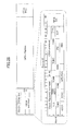
- the overhead portion has a size of 16 bytes x 4 rows of a 1 st column to a 16 th column, and is used for a management of a connection and quality.
- the OPUk payload portion has a size of 3808 bytes x 4 rows of a 17 th column to a 3824 th column, and accommodates the client signal which provides one or more services.
- the OTUkFEC portion has a size of 256 bytes x 4 rows of a 3825 th column to a 4080 th column, and is used to correct an error which occurs during transmission.
- An ODUk portion corresponds to a portion in which an overhead byte (OH) used for the management of the connection and the quality is added to the OPUk payload portion.
- the OTUk portion corresponds to a portion in which frame synchronization, the overhead byte used for the management of the connection, and the OTUkFEC portion are added to the ODUk portion.
- a frame format of the ODUflex is the same as an ODUframe format.
- the TS is decreased and increased by a control using an OPUflex overhead and a Resize Control Overhead (RCOH)1, a RCOH2, or a RCOH3 of an HO_OPUk overhead.
- RCOH Resize Control Overhead
- a frame bandwidth is varied by changing the TS number in response to an operation of a control protocol, so as to adjust the bandwidth to be suitable to accommodate the client signal. Also, it is possible to implement to change the bandwidth without disconnection.
Landscapes
- Engineering & Computer Science (AREA)
- Computer Networks & Wireless Communication (AREA)
- Signal Processing (AREA)
- Data Exchanges In Wide-Area Networks (AREA)
- Maintenance And Management Of Digital Transmission (AREA)
Abstract
Description
- The embodiments discussed herein are related to a failure protection method for a network and a node apparatus.
- In a network field, as to an optical transport technology of a next generation which is expected to expand applied fields in the future, an OTN (Optical Transport Network), which integrates TDM (Time-Division Multiplexing) data such as Synchronous Optical NETwork (SONET) / Synchronous Digital Hierarchy (SDH) and packet data such as Ethernet, is recommended by the International Telecommunication Union Telecommunication standardization sector (ITU-T).
- Regarding the OTN, there is a specification of an Optical channel Data Unit flex (ODUflex) capable of providing a variable bandwidth in response to demand in order to effectively transmit the packet data which is the current primary traffic.
- Up until now, there has been discussed a problem of protecting a transmission path with high priority in a case of switching a fault transmission line which can not be switched to a protection transmission path to a normal working transmission path which has lower priority than the fault transmission line.
- Patent Document 1: Japanese Laid-open Patent Publication No.
59-175224 - In view of the above-mentioned conventional problems, the present disclosure aims at providing a failure protection method for a network and a node apparatus in which multiple paths of working paths where failures occur are protected.
- According to one aspect of the embodiment, there is provided a failure protection method of a network connecting between nodes by multiple working paths and a protection path, the failure protection method including determining an allocation bandwidth to allocate to a detected path where a failure is detected in multiple paths being set to the multiple working paths, depending on the detected path; switching the detected path from one of the multiple working paths to the protection path; and transmitting data to be transmitted by the detected path, by using the allocation bandwidth determined within an entire bandwidth of the protection path.
-
-
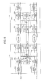
FIG. 1 is a diagram illustrating a state of a normal operation in an example of a configuration of a shared protection system in a related art; -
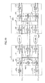
FIG. 2 is a diagram illustrating a state of double line failures in the example of the configuration of a shared protection system in the related art; -
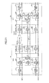
FIG. 3 is a diagram illustrating a configuration of an OTN transmission system in a first embodiment; -
FIG. 4A and FIG. 4B are block diagrams illustrating examples of hardware configurations of ODUflex control parts in the first embodiment; -
FIG. 5 is a diagram for explaining an operation when a line failure occurs in the first embodiment; -
FIG. 6 is diagram for explaining an operation when a double line failure occurs in the first embodiment; -
FIG. 7 is a flowchart for explaining a process executed by ODUflex control parts in the first embodiment; -
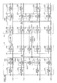
FIG. 8 is a diagram illustrating a configuration of an OTN system in a second embodiment; -
FIG. 9 is a diagram for explaining an operation when a line failure occurs in the second embodiment; -
FIG. 10 is a diagram for explaining an operation when a double line failure occurs in the second embodiment; -
FIG. 11 is a diagram for explaining an operation when a quadruple line failure occurs in the second embodiment; -
FIG. 12 is a flowchart for explaining a process executed by ODUflex control parts in the second embodiment; -
FIG. 13 is a diagram illustrating a configuration of an OTN transmission system in a third embodiment; -
FIG. 14 is a diagram for explaining an operation when a line failure occurs in the third embodiment; -
FIG. 15 is a diagram for explaining an operation when a double line failure occurs in the third embodiment; -
FIG. 16 is a diagram illustrating a configuration of an OTN transmission system in a fourth embodiment; -
FIG. 17 is a diagram illustrating ratio examples of PATH_1 to PATH_2 which are to be protected when failures occur; -
FIG. 18 is a diagram for explaining an operation when a line failure occurs in the fourth embodiment; -
FIG. 19 is a diagram for explaining an operation when a double line failure occurs in the fourth embodiment; -
FIG. 20 is a diagram illustrating a configuration of an OTN transmission system in a fifth embodiment; -
FIG. 21 is a diagram illustrating an operation when a line failure occurs in the fifth embodiment; -
FIG. 22 is a flowchart for explaining a process executed by ODUflex control parts in the fifth embodiment; -
FIG. 23 is a flowchart for explaining a process executed by ODUflex control parts in a sixth embodiment; -
FIG. 24 is a flowchart for explaining a process executed by ODUflex control parts in a seventh embodiment; -
FIG. 25 is a diagram illustrating a configuration of an OTN transmission system in an eighth embodiment; -
FIG. 26 is a diagram for explaining an operation when a line failure occurs in the eighth embodiment; -
FIG. 27 is a flowchart for explaining a process executed by ODUflex control parts in the eighth embodiment; -
FIG. 28 is a diagram illustrating a frame configuration of an example of an OTU frame; and -
FIG. 29 is a diagram illustrating a state of assigning tributaryslots TS# 1 throughTS# 8 to an HO_ODU2. -
FIG. 1 is a diagram illustrating a state of a normal operation in an example of a configuration of a shared protection system in a related art.FIG. 1 illustrates the state of the normal operation without a failure. A client signal input to a client interface (IF)part 11a is applied to aline interface part 13a via abridge part 12. The client signal is mapped into a signal in a predetermined format by theline interface part 13a, is transmitted through a workingpath 14a, is demapped to an original client signal by aline interface part 15a, is supplied to aclient interface part 17a via aswitch part 16, and is output to an outside from theclient interface part 17a. - The client signal, which is also input to
client interface parts line interface parts bridge part 12. Moreover, the client signal is mapped into the predetermined format, is transmitted throughworking paths line interface parts client interface part switch part 16, and is output to the outside from theclient interface parts switch part 16. Also, thebridge part 12 is connected to theline interface part 13d, theline interface part 13d is connected to theline interface part 15d through a sharedprotection path 14d, and theline interface part 15d is connected to theswitch part 16. -
FIG. 2 is a diagram illustrating a state of a double line failure (disconnection) in the example of the configuration of a shared protection system in the related art.FIG. 2 illustrates a state in which the double line failure (disconnection) occurs. First, when a failure occurs on the workingpath 14a, thebridge part 12 connects theclient interface part 11a to theline interface part 13d. Theswitch part 16 connects theline interface part 15d to aclient interface part 17a, and switches the workingpath 14a to the sharedprotection path 14d, so as to protect traffic. - After that, when another failure occurs on the working
path 14b having a lower priority than the workingpath 14a, the workingpath 14b is not switched to the sharedprotection path 14d. Thus, traffic through the workingpath 14b is not protected. - As described above, in a network having a configuration including
plural working paths 14a through 14c and the sharedprotection path 14d, in a case in which failures occur on more than one of the workingpaths 14a through 14c and the traffic is switched to the sharedprotection path 14d, in general, one line alone having a higher priority is switched to protect the traffic. In this case, other failure lines remain in disconnection. -
Patent Document 1 proposes a technology in which switchingapparatuses working paths protection path 6. Working path priority indicates an order of the workingpath 3, the workingpath 4, and the workingpath 5. When failures occur on theworking paths path 4 is switched to theprotection path 6, and the workingpath 3 is switched to theprotection path 5. - In the above described technology, there is a problem in which when failures occur on plural working paths, it is difficult to protect the plural working paths having the failures by the shared protection path. Also, in the technology proposed in
Patent Document 1, when the failures occur on the workingpaths path 4 is switched to theprotection path 6, and the workingpath 3 is switched to the workingpath 5. There is a problem in which the workingpath 5 having the lower priority may be disconnected. - At least a method is disclosed below in which the failures on the plural working paths are protected.
- In the following, embodiments of the present invention will be described with reference to the accompanying drawings.
-
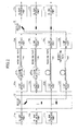
FIG. 3 is a diagram illustrating a configuration of an OTN transmission system in a first embodiment. InFIG. 3 , in anode 20, an Ethernet frame supplied from a client is received byclient interface parts ODUflex process parts ODUflex process parts - In order to map into the ODUflex, an
ODUflex control part 23 acquires a bandwidth to be used, a line state, and the like for each path by cooperating with each ofODUflex process parts part 24, and Optical channel Transport Unit 2 (OTU2)process parts ODUflex control part 23 determines a bandwidth of the ODUflex to be assigned for protection. After that, theODUflex control part 23 instructs the cross connect (XC)part 24 to conduct an actual cross connect setting. - The ODUflex frames from the
ODUflex process parts OTU2 process parts part 24, to map into ODU2. Furthermore, an overhead such as Forward Error Correction (FEC) information or the like is added to the ODUflex frames mapped into the ODU2, and is transmitted as an OTU2 frame to anode 30 being an opposite node. - In order to realize multiplex accommodation to the ODU2 at the HO side of the ODUflex frame, a Tributary Slot (TS) is defined and the ODUflex is accommodated to each TS in a payload area of the ODU2 frame. The TS is a tributary slot where an OPU2 payload area being a payload portion of the ODU2 frame is divided into ts portions. An OPU2 is an Optical Channel Payload Unit-k (OPUk) where k=2. A bandwidth for one TS is approximately 1.25 Gbps.
- In the
node 30,OTU2 process parts OTU2 process parts ODUflex process parts part 34 by the cross connect setting of anODUflex control part 33. - Each of the
ODUflex process parts client interface parts node 20 to thenode 30 is described above. Transmission from thenode 30 to thenode 20 is conducted in the same manner. - A PATH_1 connects between the
OTU2 process parts OTU2 process parts OTU2 process parts -
FIG. 4A is a block diagram illustrating an example of a hardware configuration of theODUflex control part 23.FIG. 4B is a block diagram illustrating an example of a hardware configuration of theODUflex control part 33. InFIG. 4A , theODUflex control part 23 includes aCPU 23a, amemory 23b, andcommunication parts CPU 23a, thememory 23b, thecommunication parts bus 23e. TheCPU 23a conducts each of various processes illustrated inFIG. 7 and the like by executing programs stored in thememory 23b. Also, setting data such as a threshold and the like are stored in thememory 23b. Thecommunication parts ODUflex process parts part 24, theOTU2 process parts - In
FIG. 4B , theODUflex control part 33 includes aCPU 33a, amemory 33b, andcommunication parts CPU 33a, thememory 33b, and thecommunication parts bus 33e. TheCPU 33a conducts each of the various processes illustrated inFIG. 7 and the like, by executing programs stored in thememory 33b. Also, setting data such as a threshold and the like are stored in thememory 33b. Thecommunication parts ODUflex process parts part 34, theOTU2 process parts - As illustrated in
FIG. 5 , a FAILURE_1 (line failure) occurs on the PATH_1 in a direction from thenode 20 to thenode 30 between theOTU2 process parts FIG. 5 . - Sequence (SQ1): The
OTU2 process part 35a of thenode 30 at a receiver side detects Loss Of Signal (LOS) of the PATH_1, and theODUflex control part 33 of thenode 30 collects alarm information. After that, theODUflex control part 33 sends the alarm information in the overhead of the OTU2 frame from theOTU2 process part 35a to thenode 20. A Backward Defect Indication (BDI), General Communication Channel 0 (GCC0), Automatic Protection Switching coordination channel (APS), and the like are used. - Sequence (SQ2): The
OTU2 process part 25a of thenode 20 detects the alarm information from the overhead of the OTU2 frame, and reports a failure state of the PATH_1 to theODUflex control part 23. - Sequence (SQ3): Each of the
ODUflex control parts node 20 andnode 30, respectively, determines the bandwidth to be used of the shared protection path and a bandwidth to set the working path of the PATH_1, in which the FAILURE_1 occurs, to the shared protection path. - A bandwidth Bs [TS], which is set to the shared protection path for each path, is calculated by an expression (1) based on all bandwidths Ba [TS] of the shared protection path, a bandwidth Bb [TS] of the working path where the failure occurs, and a total bandwidth Bt [TS] of all working paths on which the failures occur.

- In the expression (1), since Ba = 8 [TS], Bb = 8 [TS], and Bt = 8 [TS], Bs = 8 TSs are assigned for the shared protection path of the PATH_1.
- Sequence (SQ4): the
ODUflex control part 23 of thenode 20 conducts the cross connect setting of the ODUflex frame of the PATH_1 so as to pass the shared protection path by the bandwidth Bs [TS]. Data are transmitted via the shared protection path. - Sequence (SQ5): The
ODUflex control part 33 of thenode 30 instructs the cross connect (XC)part 34 to supply a shared protection path of the PATH_1 of 8 TSs from multiple shared protection paths by conducting the cross connect setting to the cross connect (XC)part 34. Then, an operation starts. - Next, as depicted in
FIG. 6 , in addition to the FAILURE_1 of the PATH_1, another FAILURE_2 occurs on the PATH_2. TheOTU2 process part 35b of thenode 30 at the receiver side detects the LOS of the PATH_2, and theODUflex control part 33 of thenode 30 collects the alarm information. TheODUflex control part 33 of thenode 30 sends the alarm information by the overhead of the OTU2 frame from theOTU2 process part 35b to thenode 20. - Each of the
ODUflex control parts - The
ODUflex control parts nodes parts ODUflex process parts ODUflex parts - Moreover, by using the TS number (= 4 TSs) based on the determined bandwidth, the
ODUflex control part 23 of thenode 20 conducts the cross connect setting so as for the ODUflex frame of the PATH_2 to pass the shared protection path, that is, to pass theOTU2 process part 25x. Data are transmitted via the shared protection path. Also, theODUflex control part 33 of thenode 30 conducts the cross connect setting to the cross connect (XC)part 34 to supply 4 TSs of the PATH_2 where the bandwidth is assigned to the shared protection path. Then, the operation starts. By instructions of theODUflex control parts ODUflex process parts -
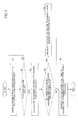
FIG. 7 is a flowchart for explaining a process executed by theODUflex control parts FIG. 7 , in step S1, theODUflex control part 23 receives information pertinent to each state of paths of the working path from theOTU2 process parts OTU2 process parts - In step S2, it is determined whether a new failure occurs. If the new failure does not occur, the
ODUflex control part 23 goes back to step S1 If the new failure occurs, in step S3, theODUflex control part 23 calculates the TS number for each path to assign to the shared protection path by the expression (1). In step S4, theODUflex control part 23 determines whether there is a path which has been switched to the shared protection path. - In a case in which there is the path which has been switched to the shared protection path, in step S5, the
ODUflex control part 23 instructs the cross connect (XC)part 24 to delete the TS number, which is demanded to delete, from the shared protection path, and advances to step S6. If there is no path which has been switched to the shared protection path, theODUflex control part 23 advances to step S6 without deleting the TS number. - In step S6, the
ODUflex control parts parts ODUflex control parts ODUflex process parts node 20 and theODUflex process parts node 30, respectively, to conduct the path resizing process for changing the TS number of the path to protect, by using the LCR protocol and the BWR protocol. After that, theODUflex control parts - When the FAILURE_2 of the PATH_2 is recovered, the
ODUflex control parts - After that, the
ODUflex control parts nodes parts ODUflex parts ODUflex control parts ODUflex process parts ODUflex process parts -
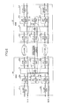
FIG. 8 is a diagram illustrating a configuration of an OTN system in a second embodiment. InFIG. 8 , at thenode 20, the Ethernet frame supplied from the client is received byclient interface parts ODUflex process parts ODUflex process parts 22a through 22e map the Ethernet frame into the ODUflex which is the accommodation format at the LO side of the OTN. - In a case of mapping into the ODUflex, the
ODUflex control part 23 coordinates with each of theODUflex process parts 22a through 22e, the cross connect (XC)part 24,OTU2 process parts 25a through 25d being interfaces at the network side, and anOTU3 process part 25y, and acquires the bandwidth to be used and the line state pertinent to each of paths. Also, the bandwidth of the ODUflex for the protection to assign is determined. After that, theODUflex control part 23 instructs the cross connect (XC)part 24 to conduct the actual cross connect setting. - The ODUflex frame from the
ODUflex process parts 22a through 22d is supplied to theOTU2 process parts 25a through 25d at the HO side through the cross connect (XC)part 24, and is mapped into the ODU2. Moreover, the overhead such as the FEC information or the like is added to the ODUflex frame. The ODUflex frame is transmitted as the OTU2 frame toOTU2 process parts 35a through 35d of thenode 30 being the opposite node. - Also, the ODUflex frame supplied to the
OTU3 process part 25y is mapped to an ODU3. Moreover, the overhead such as the FEC information or the like is added to the ODUflex frame. The ODUflex frame is transmitted as an OTU3 frame to anOTU3 process part 35y of thenode 30 being the opposite node. - At the
node 30, by theOTU2 process parts 35a through 35d, and theOTU3 process part 35y, the OTU2 frame or an OTU3 signal transmitted through the network is received and the ODU2 or the ODU3 are extracted. Moreover, the ODUflex frame is demapped from the ODU2 or the ODU3. The ODUflex frame, which is output from theOTU2 process parts 35a through 35d and theOTU3 process part 35y, is supplied to theODUflex process parts 32a through 32e through the cross connect (XC)part 34 by the cross connect setting of theODUflex control part 33. - Each of the
ODUflex process parts 32a through 32e demaps from the ODUflex frame to the Ethernet frame. The Ethernet frame is supplied fromclient interface parts 31a through 31e to the client. The transmission from thenode 20 to thenode 30 is described above. The transmission from thenode 30 to thenode 20 is conducted in the same manner. - A PATH_1 is bi-directional to connect between the
OTU2 process parts OTU2 process parts OTU2 process parts OTU2 process parts OTU3 process parts - The priorities of the PATH_1 through the PATH_4 are higher than that of the shared PATH_5. The priorities of the PATH_1 through the shared PATH_5 are stored beforehand in the
memories ODUflex control parts - As described in
FIG. 9 , the FAILURE_1 (line failure) occurs on the PATH_1 between theOTU2 process parts ODUflex control parts node 20 and thenode 30 determine the bandwidth to assign to the shared protection path of the shared PATH_5, from the bandwidth of the working path where the FAILURE_1 occurs. TheODUflex control parts parts ODUflex control parts ODUflex process parts ODUflex process parts - Next, as illustrated in
FIG. 10 , the FAILURE_2 (line failure) occurs on the PATH_2 between theOTU2 process parts ODUflex control parts parts ODUflex control parts ODUflex process parts ODUflex process parts - Furthermore, as illustrated in
FIG. 11 , a FAILURE_3 and a FAILURE_4 (line failures) occur on the PATH_3 and the PATH_4 between theOTU2 process parts OTU2 process parts ODUflex control parts parts -
FIG. 12 is a flowchart for explaining a process executed by theODUflex control parts FIG. 12 , in step S10, the priority is set for each path to use to switch for the failure. In step S11, theODUflex control part 23 receives information pertinent to each state of the paths of the working paths from theOTU2 process parts 25a through 25d. - In step S12, the
ODUflex control part 23 determines whether a new failure occurs. If no new failure occurs, theODUflex control part 23 goes back to step S11. When the new failure occurs, in step S13, theODUflex control part 23 deletes the bandwidth of a shared path having the lower priority than other paths where the failures occur, and calculates the TS number for each of the paths to assign to the shared protection path of the shared path by the expression (1). The bandwidth of the shared path is used as all bandwidths Ba [TS] for the shared protection path. - In step S14, the
ODUflex control part 23 determines whether there is a path which has been switched to the shared protection path. - In a case in which there is the path which has been switched, in step S15, the
ODUflex control part 23 instructs the cross connect (XC)part 24 to delete the TS number from the shared protection path of the shared path having the lower priority than other paths where the failures occur. Then, theODUflex control part 23 advances to step S16. If there is no path which has been switched, theODUflex control part 23 advances to step S16 without deleting the TS number. - In step S16, the
ODUflex control parts parts ODUflex control parts node 20 and thenode 30 instruct theODUflex process parts 22a to 22e and 32a to 32e to switch the TS number of the path to protect by using the LCR protocol and the BWR protocol. After that, this process advances to step S11. -
FIG. 13 is a diagram illustrating a configuration of an OTN transmission system in a third embodiment. InFIG. 13 , parts that are the same as those inFIG. 3 are indicated by the same reference numerals and the explanation thereof will be omitted. - In
FIG. 13 , the PATH_1 is bi-directional, and connects between theOTU2 process parts OTU2 process parts OTU2 process parts - Also, the ratios of the PATH_1 and the PATH_2 to protect is set and stored beforehand in the
memories ODUflex control parts - As illustrated in
FIG. 14 , the FAILURE_1 (line failure) occurs between theOTU2 process part FIG. 14 . - Sequence (SQ11): At the receiver side, the
OTU2 process part 35a of thenode 30 detects the LOS of the PATH_1, and theODUflex control part 33 of thenode 30 collects the alarm information. Then, theODUflex control part 33 of thenode 30 sends the alarm information by using the overhead of the OTU2 frame from theOTU2 process part 35a to thenode 20 being the opposite node. - Sequence (SQ12): The
OTU2 process part 25a of thenode 20 detects the alarm information from the overhead of the OTU2 frame, and reports the failure state of the line to theODUflex control part 23. - Sequence (SQ13): The
ODUflex control parts nodes - Sequence (SQ14): Since the ratio of the PATH_1 set in the
memory 23b indicates 75%, theODUflex control part 23 of thenode 20 assigns the bandwidth of the shared protection path, that is, 6 TSs corresponding to 75% of 8 TSs to the PATH_1, conducts the cross connect setting so that the ODUflex frame of the 6 TSs of the PATH_1 passes the shared protection path, and sends data through the shared protection path. - Sequence (SQ15): The
ODUflex control part 33 of thenode 30 instructs the cross connect setting to the cross connect (XC)part 34 so that the shared protection path of 6 TSs of the PATH_1 is supplied from the shared protection path. The operation starts. Then, by the instruction of theODUflex control parts ODUflex process parts - Next, as illustrated in
FIG. 15 , in addition to the FAILURE_1 of the PATH_1, the FAILURE_2 occurs on the PATH_2. Sequence numbers are also indicated with parentheses inFIG. 15 . - Sequence (SQ16): At the receiver side, the
OTU2 process part 35b of thenode 30 detects the LOS of the PATH_2, theODUflex control part 33 of thenode 30 collects the alarm information. TheODUflex control part 33 of thenode 30 sends the alarm information by using the overhead of the OTU2 frame from theOTU2 process part 35b to thenode 20 being the opposite node. - Sequence (SQ17): The
ODUflex control parts nodes - Sequence (SQ18): Since the ratio of the PATH_2 set in the
memory 23b indicates 25%, theODUflex control part 23 of thenode 20 assigns the bandwidth of the shared protection path, that is, 2 TSs corresponding to 25% of 8 TSs, and conducts the cross connect setting so that the ODUflex frame of 2 TSs of the PATH_2 passes the shared protection path. Data are sent through the shared protection path. - The
ODUflex control part 33 of thenode 30 instructs the cross connect setting to the cross connect (XC)part 34 so as to supply the shared protection path of 2 TSs of the PATH_2 from the shared protection path to theODUflex process part 22b. The operation starts. After that, by the instructions of theODUflex control parts ODUflex process parts - A flowchart for the process executed by the
ODUflex control parts FIG. 12 . However, the ratios of the PATH_1 and the PATH_2 to protect from the FAILURE_1 and FAILURE_2 in step S10 are set. In step S13, the TS number for each of the FAILURE_1 and FAILURE_2 is calculated based on the ratios of the PATH_1 and the PATH_2, respectively. -
FIG. 16 is a diagram illustrating a configuration of an OTN transmission system in a fourth embodiment. InFIG. 16 , parts that are the same as those inFIG. 13 are indicated by the same reference numerals and the explanation thereof will be omitted. - In
FIG. 16 , the PATH_1 is bi-directional, connects between theOTU2 process parts OTU2 process parts OTU2 process parts - Also, the ratios of the PATH_1 and the PATH_2 to protect is set and stored beforehand in the
memories ODUflex control parts FIG. 17 , regarding the ratios of the PATH_1 and the PATH_2 to protect in a case in that the FAILURE_1 and the FAILURE_2 occur, in a term T1, 75 % is set for the PATH_1 and 25 % is set for the PATH_2. In a term T2, 25 % is set for the PATH_1, and 75 % is set for the PATH_2. The term T1 and the term T2 are alternately repeated. - As illustrated in
FIG. 18 , the FAILURE_1 occurs between theOTU2 process parts FIG. 18 . - Sequence (SQ21): At the receiver side, the
OTU2 process part 35a of thenode 30 detects the LOS of the PATH_1, and theODUflex control part 33 of thenode 30 collects the alarm information. Then, theODUflex control part 33 of thenode 30 sends the alarm information by using the overhead of the OTU2 frame from theOTU2 process part 35a to thenode 20 being the opposite node. - Sequence (SQ22): The
OTU2 process part 25a of thenode 20 detects the alarm information from the overhead of the OTU2 frame, and reports the failure state of the working path to theODUflex control part 23. - Sequence (SQ23): The OTU2
flex control parts nodes - Sequence (SQ24): Since the ratio of the PATH_1 in the term T1 set in the
memory 23b, theODUflex control part 23 of thenode 20 assigns the bandwidth of the shared protection path, that is, 6 TSs corresponding to 75 % of 8 TSs, conducts the cross connect setting so as to pass the ODUflex frame of 6 TSs of the PATH_1, and transmits data via the shared protection path. - Sequence (SQ25): The
ODUflex control part 33 of thenode 30 instructs the cross connect setting to the cross connect (XC)part 34 so as to supply the shared protection path of 6 TSs of the PATH_1 from the shared protection path to theODUflex process part 32a. The operation starts. After that, by the instructions of theODUflex control parts ODUflex process parts - Next, as illustrated in
FIG. 19 , in addition to the FAILURE_1 of the PATH_1, the FAILURE_2 occurs on the PATH_2. Sequence numbers are also indicated with parentheses inFIG. 19 . - Sequence (SQ26): At the receiver side, the
OTU2 process part 35b of thenode 30 detects the LOS of the PATH_2, and theODUflex control part 33 of thenode 30 collects the alarm information. TheODUflex control part 33 of thenode 30 sends the alarm information by the overhead of the OTU2 frame from theOTU2 process part 35b to thenode 20 being the opposite node. - Sequence (SQ27): The
ODUflex control parts nodes - Sequence (SQ28): Since the ratio of the PATH_2 set in the
memory 23b indicates 25 % in the term T1, theODUflex control part 23 of thenode 20 assigns the bandwidth of the shared protection path, that is, 2 TSs corresponding to 25 % of 8 TSs, conducts the cross connect setting so that the ODUflex frame of 2 TSs of the PATH_2 passes the shared protection path, and sends data via the shared protection path. - The
ODUflex control part 33 of thenode 30 instructs the cross connect setting to the cross connect (XC)part 34 so as to supply the shared protection path of 2 TSs of the PATH_2 from the shared protection path to theODUflex process part 32b. The operation starts. After that, by the instructions of theODUflex control parts ODUflex process parts - Next, when the term T1 ends and the term T2 starts, the
ODUflex control parts nodes parts ODUflex parts - Similarly, when the term T2 ends and the term T1 starts, the
ODUflex control parts nodes parts ODUflex parts -
FIG. 20 is a diagram illustrating a configuration of an OTN transmission system in a fifth embodiment. InFIG. 20 , parts that are the same as those inFIG. 13 are indicated by the same reference numerals and the explanation thereof will be omitted. - In
FIG. 20 , the PATH_1 is bi-directional, connects between theOTU2 process parts OTU2 process parts OTU2 process parts memories ODUflex control parts - The following sequence numbers are also indicated with parentheses in
FIG. 20 . - Sequence (SQ31): The
OTU2 process parts ODUflex control parts OTU2 process parts ODUflex control parts - As illustrated in
FIG. 21 , a FAILURE_1 occurs between theOTU2 process parts OTU2 process part 35a is degraded. Sequence numbers are also indicated with parentheses inFIG. 21 . - Sequence (SQ32): At the receiver side, the
OTU2 process part 35a of thenode 30 detects the FEC correction number for the OTU2 including the PATH_1. - Sequence (SQ33): The
OTU2 process part 35a detects that the FEC correction number of the OTU2 including the PATH_1 exceeds the threshold for the protection path preparation (which is arbitrary set) and transmission channel quality is degraded. - Sequence (SQ34): The
ODUflex control part 23 conducts the cross connect setting so that the bandwidth for 1 TS in the ODTflex frame of 8 TSs of the PATH_1 passes the shared protection path. By the cross connect setting, data for 1 TS are transmitted through the shared protection path. At this point, quality is degraded with no actual failure, in which the LOS is not detected. Accordingly, at thenode 30, the switching process is not performed to switch from the working path to the protection path. - Sequence (SQ35): Since the quality is further degraded, the actual failure occurs such that the LOS is detected on the PATH_1.
- Sequence (SQ36): The
OTU2 process part 35a of thenode 30 detects the LOS of the PATH_1, and theODUflex control part 33 of thenode 30 collects the alarm information. After that, theODUflex control part 33 of thenode 30 sends the alarm information by the overhead of the OTU2 frame from theOTU2 process part 35a to thenode 20 being the opposite node. - Sequence (SQ37): The
ODUflex control part 33 instructs the cross connect setting to the cross connect (XC)part 34 so as to supply the shared protection path of 1 TS of the PATH_1 to theODUflex process part 32a. The operation starts. - Sequence (SQ38): The
ODUflex control part 23 of thenode 20 instructs the cross connect setting to the cross connect (XC)part 24 so as to increase the shared protection path of the PATH_1 from 1 TS to 8 TS. TheODUflex control part 33 instructs the cross connect setting to the cross connect (XC)part 34 to supply the shared protection path of 8 TSs of the PATH_1 to theODUflex process part 32a. The operation starts with 8 TSs. -
FIG. 22 is a flowchart for explaining a process executed by the ODUflex control parts in a fifth embodiment. InFIG. 22 , in step S21, theODUflex control part 23 receives information such as the FEC correction number and the like pertinent to a state of the path of the working paths from theOTU2 process parts - In step S22, the
ODUflex control part 23 determines whether the FEC correction number of the working path exceeds the threshold for the protection path preparation. If the FEC correction number of the working path does not exceed the threshold for the protection path preparation, theODUflex control part 23 advances to step S21. If the FEC correction number of the working path exceeds the threshold for the protection path preparation, in step S23, theODUflex control part 23 conducts the cross connect setting so that the bandwidth for 1 TS in the ODUflex frame of the path (referred as the PATH_1), in which the FEC correction number of the working path exceeds the threshold for the protection path preparation, passes the shared protection path. Data for 1 TS are transmitted through the shared protection path. - Next, in step S24, the
ODUflex control part 23 determines whether a new failure occurs. If no new failure occurs, theODUflex control part 23 advances to step S21. If the new failure occurs, in step S25, theODUflex control part 33 instructs the cross connect setting to the cross connect (XC)part 34 so that the shared protection path for 1 TS of the PATH_1 is supplied to theODUflex process part 32a. In step S26, theODUflex control part 23 calculates the TS number for each path to assign to the shared protection path by the expression (1). - Next, in step S27, the
ODUflex control part 23 determines whether there is a path which has been switched to the shared protection path. - If there is the path which has been switched to the shared protection path, in step S28, the
ODUflex control part 23 instructs the cross connect (XC)part 24 to delete the TS number demanded to be deleted from the shared protection path, and advances to step S29. If there is no path which has been switched, theODUflex control part 23 directly advances to step S29 without deleting the TS number. - In step S29, the
ODUflex control part 23 instructs the cross connect (XC)part 24 to delete paths on the shared protection path other than the path to protect. - In step S30, the
ODUflex control parts parts ODUflex control parts ODUflex process parts - In the fifth embodiment, it is possible to rapidly switch the working path where the failure occurs to the shared protection path when the failure occurs.
- A sixth embodiment corresponds to a variation of the fifth embodiment. A configuration of the OTN transmission system in the sixth embodiment is the same as that illustrated in
FIG. 20 . However, multiple thresholds for protection path preparation and multiple preparation TS numbers respective to the multiple threshold are set and stored in thememories ODUflex control parts -
FIG. 23 is a flowchart for explaining a process executed by theODUflex control parts FIG. 23 , in step S40, the first through fourth thresholds for the protection path preparation and the preparation TS numbers respective to the first through fourth thresholds are set in thememories - In step S41, the
ODUflex control part 23 receives the information such as the FEC correction number or the like pertinent to the state of the path of the working path from theOTU2 process parts - In step S42, the
ODUflex control part 23 determines whether the FEC correction number of the working path exceeds each of the first through fourth thresholds. If the FEC correction number does not exceed any of the first through fourth thresholds, theODUflex control part 23 advances to step S41. If the FEC correction number of the working path exceeds at least one of the first through fourth thresholds, in step S43, theODUflex control part 23 conducts the cross connect setting so that in the ODUflex frames of the path in which the FEC correction number exceeds at least one of the first through fourth thresholds, preparation TS numbers (2 TSs, 4 TSs, 6 TSs, or 8 TSs) respective to values (the first through fourth thresholds) which the FEC correction number exceeds pass the cross connect setting. Data for 2 TSs through 8 TSs are transmitted via the shared protection path. - Next, in step S44, the
ODUflex control part 23 determines whether a new failure occurs. If the new failure does not occur, theODUflex control part 23 advances to step S41. If the new failure occurs, in step S45, theODUflex control part 23 instructs the cross connect (XC)part 34 to conduct the cross connect setting so as to supply the shared protection path for the preparation TS number (2 TSs, 4 TSs, 6 TSs, or 8 TSs) of the path where the new failure occurs. In step S46, theODUflex control part 23 calculates the TS number for each of the paths to assign to the shared protection path. - Next, in step S47, the
ODUflex control part 23 determines whether there is the path which has been switched to the shared protection path. - If there is the path which has been switched to the shared protection path, in step S48, the
ODUflex control part 23 instructs the cross connect (XC)part 24 to delete the TS number demanded to delete from the shared protection number, and advances to step S49. If there is no path which has been switched, theODUflex control part 23 instructs the cross connect (XC)part 24 advances to step S49 without deleting the TS number. - In step S49, the
ODUflex control part 23 instructs the cross connect (XC)part 24 to delete the path on the shared protection path other than the path to protect. - In step S50, the
ODUflex control parts parts ODUflex control parts 23 instructs theODUflex process parts - In the sixth embodiment, it is possible to rapidly switch the working path where the failure occurs to the shared protection path when the failure occurs.
- A seventh embodiment corresponds to another variation of the fifth embodiment. A configuration of the OTN transmission system in the seventh embodiment is the same as that illustrated in
FIG. 20 . However, the threshold for the protection path preparation, the preparation TS number (= 1 TS), and a threshold for switching the path are set and stored in thememories ODUflex control parts -
FIG. 24 is a flowchart for explaining a process executed by theODUflex control parts FIG. 24 , parts that are the same as those inFIG.22 are indicated by the same reference numerals and the explanation thereof will be omitted. InFIG. 24 , in step S21, theODUflex control part 23 receives information such as the FEC correction number pertinent to the state of the path of the working path or the like from theOTU2 process parts - In step S22, the
ODUflex control part 23 determines whether the FEC correction number of the working path exceeds the threshold for the protection path preparation. If the FEC correction number does not exceed the threshold for the protection path preparation, theODUflex control part 23 advances to step S21. If the FEC correction number of the working path exceeds the threshold for the protection path preparation, in step S23, theODUflex control part 23 conducts the cross connect setting so that the bandwidth of 1 TS in the ODUflex frame of the path (may be referred as the PATH_1), in which the FEC correction number of the working path exceeds the threshold for the protection path preparation, passes the shared protection path. Accordingly, data are transmitted for 1 TS via the shared protection path. - Next, in step S34, the
ODUflex control part 23 determines whether the FEC correction number of the working path exceeds the threshold for the switching process. If the FEC correction number does not exceed the threshold for the switching process, theODUflex control part 23 advances to step S21. If the FEC correction number exceeds the threshold for the switching process, in step S25, theODUflex control part 33 instructs the cross connect (XC)part 34 to conduct the cross connect setting to supply the shared protection path of 1 TS of the PATH_1 to theODUflex process part 32a. In step S26, theODUflex control part 23 calculates the TS number for each path to assign to the shared protection path by the expression (1). - Next, in step S27, the
ODUflex control part 23 determines whether there is the path which has been switched to the shared protection path. - If there is the path which has been switched, in step S28, the
ODUflex control part 23 instructs the cross connect (XC)part 24 to delete the TS number demanded to delete from the shared protection path, and advances to step S29. If there is no path which has been switched, theODUflex control part 23 advances to step S29. - In step S29, the
ODUflex control part 23 instructs the cross connect (XC)part 24 to delete the path on the shared protection path other than the path to protect. - In step S50, the
ODUflex control parts parts ODUflex control parts ODUflex process parts - In the seventh embodiment, it is possible to rapidly switch the working path where the failure occurs to the shared protection path when the failure occurs.
-
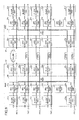
FIG. 25 is a diagram illustrating a configuration of an OTN transmission system in the eighth embodiment. InFIG. 25 , in thenode 20, the Ethernet frame supplied from the client is received by theclient interface parts 21a through 21h, and is supplied to theODUflex process parts 22a through 22h. TheODUflex process parts 22a through 22h map the Ethernet frame into the ODUflex which is the accommodation format at the LO side of the OTN. - In a case of mapping the ODUflex into the ODU2, the
ODUflex control parts 23 comprehends the bandwidth to be used and the line state pertinent to each of the paths and determines the bandwidth of the ODUflex to be assigned for the protection, by coordinating with each of theODUflex process parts 22a through 22h, the cross connect (XC)part 24, and theOTU2 process parts 25a to 25d, 25e to 25h, and 25x which are interfaces at the network side, in thenode 20. After that, theODUflex control part 23 instructs the actual cross connect setting to the cross connect (XC)part 24. In the eighth embodiment, in a normal operation without the failure, in the cross connect (XC)part 24, a cross connect is performed for data for each bandwidth for 1 TS of the PATH_1 through PATH_8 of the working paths, to theOTU2 process part 25x. - The ODUflex frame from the
ODUflex process parts 22a through 22h is supplied to theOTU2 process parts 25a through 25h or 25x at the HO side through the cross connect (XC)part 24, and is mapped into the ODU2. Moreover, the overhead such as the FEC information or the like is added to the ODUflex frame mapped into the ODU2, and the ODUflex frame is transmitted as the OTU2 frame to theOTU2 process parts 35a to 35d, 35e to 35h and 35x of thenode 30 of the opposite node. - In the
node 30, theOTU2 process parts 35a through 35h and 35x receive the OTU2 frame transmitted through the network, and extract the ODU2. Moreover, the ODUflex frame is demapped from the ODU2. The ODUflex frame, which is output fromOTU2 process parts 35a through 35h and 35x, is supplied to theODUflex process parts 32a through 32h through the cross connect (XC)part 34 by the cross connect setting of theODUflex control part 33. - Each of the
ODUflex process parts 32a through 32h demaps the Ethernet frame from the ODUflex frame. The Ethernet frame is supplied from theclient interface parts 31a through 31h to the client. Transmission from thenode 20 to thenode 30 is described above. Transmission from thenode 30 to thenode 20 is conducted in the same manner. - The PATH_1 connects in a bi-direction between the
OTU2 process parts OTU2 process parts OTU2 process parts OTU2 process parts - Also, the PATH_5 connects in the bi-direction between the
OTU2 process parts OTU2 process parts OTU2 process parts - As illustrated in
FIG. 26 , the FAILURE_1 occurs on the PATH_1 in a direction from thenode 20 to thenode 30 between theOTU2 process parts FIG. 26 . - Sequence (SQ41): At the receiver side, the
OTU2 process part 35a of thenode 30 detects the LOS of the PATH_1, and theODUflex control part 33 of thenode 30 collects the alarm information. Then, theODUflex control part 33 of thenode 30 sends the alarm information to thenode 20 being the opposite node by using the overhead of the OTU2 frame from theOTU2 process part 35a. - Sequence (SQ42): The
OTU2 process part 25a of thenode 20 detects the alarm information from the overhead of the OTU2 frame, and reports the failure state of the PATH_1 to theODUflex control part 23. - Sequence (SQ43): The
ODUflex control part 33 of thenode 30 instructs the cross connect setting to the cross connect (XC)part 34 to supply the shared protection path of 1 TS of the PATH_1 to theODUflex process part 32a. Then, the operation starts. - Sequence (SQ44): The
ODUflex control part 23 of thenode 20 determines a use bandwidth of the shared protection path and the bandwidth to set the working path of the PATH_1 where the FAILURE_1 occurs to the shared protection path, by the expression (1). - Sequence (SQ45): The
ODUflex control part 23 of thenode 20 deletes a first TS from each of the PATH_2 through PATH_8 on the shared protection path. - Sequence (SQ46): The
ODUflex control part 23 of thenode 20 instructs the cross connect (XC)part 24 to increase the ODUflex frame of the PATH_1 carried on the shared protection path from 1 TS to the bandwidth Bs = 8 TSs calculated by the expression (1). - Sequence (SQ47): The
ODUflex control part 33 of thenode 30 instructs the cross connection setting to the cross connect (XC)part 34 to supply the shared protection path of the PATH_1 of 8 TSs from the shared protection path to theODUflex process part 32a. Then, the operation starts. -
FIG. 27 is a flowchart for explaining a process executed by theODUflex control parts FIG. 27 , in step S60, theODUflex control part 23 sets to transmit data of the bandwidth for 1 TS in each of multiple paths of the working paths through the shared protection path. - In step S61, the
ODUflex control part 23 receives the information such as the FEC correction number pertinent to each state of the paths of the working paths from theOTU2 process parts 25a to 25d, 25e to 25h, and 25x. - Next, in step S62, the
ODUflex control part 23 determine whether a new failure occurs. If the new failure does not occur, theODUflex control part 23 advances to step S61. If the new failure occurs, in step S63, theODUflex control part 33 instruct the cross connect (XC)part 34 to conduct the cross connect setting so as to supply the shared protection path of 1 TS of the PATH_1 to theODUflex process part 32a. In step S64, theODUflex control part 23 calculates the TS number for each of the paths to assign to the shared protection path by the expression (1). - Next, in step S65, the
ODUflex control part 23 determines whether there is the path which has been switched to the shared protection path. - If there is the path which has been switched, in step S66, the
ODUflex control part 23 instructs the cross connect (XC)part 24 to delete the TS number demanded to delete from the shared protection, and advances to step S67. If there is no path which has been switched, theODUflex control part 23 advances to step S67 without deleting the TS number. - In step S67, the
ODUflex control part 23 instructs the cross connect (XC)part 24 to delete the path on the shared protection path other than the path to protect. - In step S68, the
ODUflex control parts parts ODUflex control parts ODUflex process parts 22a to 22d, 22e to 22h, 32a to 32d, and 32e to 32h to conduct the path resizing process for changing the TS number of the path to protect by using the LCR protocol and the BWR protocol. After that, this process is terminated. - In the eighth embodiment, it is possible to rapidly switch the working path where the failure occurs to the shared protection path when the failure occurs.
-
FIG. 28 is a diagram illustrating a frame configuration of an example of the OTU frame. The OTU frame includes an overhead portion, an OPUk (k denotes 0 or a positive integer) payload portion, and OTUkFEC (Optical channel Transport Unit k Forward Error Correction). - The overhead portion has a size of 16 bytes x 4 rows of a 1st column to a 16th column, and is used for a management of a connection and quality. The OPUk payload portion has a size of 3808 bytes x 4 rows of a 17th column to a 3824th column, and accommodates the client signal which provides one or more services. The OTUkFEC portion has a size of 256 bytes x 4 rows of a 3825th column to a 4080th column, and is used to correct an error which occurs during transmission. An ODUk portion corresponds to a portion in which an overhead byte (OH) used for the management of the connection and the quality is added to the OPUk payload portion. Also, the OTUk portion corresponds to a portion in which frame synchronization, the overhead byte used for the management of the connection, and the OTUkFEC portion are added to the ODUk portion.
- The BDI used to send the alarm information is assigned to an OTUk overhead of a first row of a 10th column. The GCC0 is assigned to the OTUk over head of the first row of each of an 11th and 12th column. The APS is assigned to the ODUk overhead of a fourth row of a 5th to 8th columns.
FIG. 29 illustrates a state of assigning tributaryslots TS# 1 throughTS# 8 in which the bandwidth is approximately 1.25 Gbps to the HO_ODU2. - Regarding the ODUflex frame, a frame format of the ODUflex is the same as an ODUframe format. In the ODUflex frame, it is possible to vary the bandwidth with hitless in which data being transmitted is not blocked by a tributary slot unit of 1. 25 G. The TS is decreased and increased by a control using an OPUflex overhead and a Resize Control Overhead (RCOH)1, a RCOH2, or a RCOH3 of an HO_OPUk overhead. For the ODUflex frame, a frame bandwidth is varied by changing the TS number in response to an operation of a control protocol, so as to adjust the bandwidth to be suitable to accommodate the client signal. Also, it is possible to implement to change the bandwidth without disconnection.
- Moreover, in a case of forming the shared protection path in the network, it is possible to assign all bandwidths to save a single working path, and to simultaneously save multiple working paths by dividing the bandwidth. Furthermore, in the above described configuration for sending the ODUflex frame to both the working path and the shared protection path between
nodes - As described above, according to the first to the eighth embodiments, it is possible to protect multiple paths of the working paths where failures occur.
Claims (18)
- A failure protection method of a network connecting between nodes (20, 30) by multiple working paths and a protection path, the failure protection method is characterized by:determining an allocation bandwidth to allocate to a detected path where a failure is detected in multiple paths being set to the multiple working paths, depending on the detected path;switching the detected path from one of the multiple working paths to the protection path; andtransmitting data to be transmitted by the detected path, by using the allocation bandwidth determined within an entire bandwidth of the protection path.
- The failure protection method as claimed in claim 1, characterized in that the allocation bandwidth to allocate to the detected path where the failure is detected is determined by multiplying a ratio of a bandwidth of the detected path to a total bandwidth of entire paths in each of which the failure is detected, with the entire bandwidth of the protection path.
- The failure protection method as claimed in claim 1, characterized in that a ratio of the allocation bandwidth to allocate to the detected path where the failure is detected is set beforehand for each of the multiple paths.
- The failure protection method as claimed in claim 1, characterized in that a ratio of a protection bandwidth to allocate to the detected path is set beforehand depending on time for each of the multiple paths.
- The failure protection method as claimed in claim 1, characterized in that for a path where an error exceeds a first threshold which is set beforehand in the multiple paths being set to the multiple working paths, a path setting is conducted to the protection path in order to protect the path exceeding the first threshold.
- The failure protection method as claimed in claim 5, characterized in that when the failure is detected on the path where the error rate exceeds the first threshold, the detected path is switched from the working path in which the path setting is conducted, to the protection path.
- The failure protection method as claimed in claim 5, characterized in that in first data transmitted by the path where an error exceeds a first threshold, second data of a rate corresponding to the first threshold are transmitted by the allocation bandwidth determined within the entire bandwidth of the protection path where the path setting is conducted.
- The failure protection method as claimed in claim 5, characterized in that when the error rate of a path being set to the working path exceeds a second threshold being greater than the first threshold, the path in which the error rate exceeds the second threshold is switched from the working path to the protection path where the path is set.
- A failure protection method in which multiple working paths and a protection path connect between nodes (20, 30), wherein
a transmitter node transmits partial data respective to the multiple working paths by using the protection path,
a receiver node switches a working path where a failure is detected to the partial data transmitted by using the protection path when the failure is detected,
the transmitter node determines a bandwidth of the protection path which is assigned for the working path where the failure is detected at the receiver node, and
transmits data of the working path where the failure is detected by using the bandwidth determined within the protection path. - A node apparatus in a network connecting between nodes (20, 30) by multiple working paths and a protection path, the node apparatus comprising:a determination part configured to determine an allocation bandwidth to allocate to a detected path where a failure is detected in multiple paths being set to the multiple working paths, depending on the detected path;a switch part configured to switch the detected path from one of the multiple working paths to the protection path; andtransmission part configured to transmit data to be transmitted by the detected path, by using the allocation bandwidth determined within an entire bandwidth of the protection path.
- The node apparatus as claimed in claim 10, characterized in that the determination part determines the allocation bandwidth to allocate to the detected path where the failure is detected, by multiplying a ratio of a bandwidth of the detected path to a total bandwidth of entire paths in each of which the failure is detected, with the entire bandwidth of the protection path.
- The node apparatus as claimed in claim 10, characterized in that the determination part uses a ratio of the allocation bandwidth to allocate to the detected path where the failure is detected, in which the ratio is set beforehand for each of the multiple paths.
- The node apparatus as claimed in claim 12, characterized in that a ratio of a protection bandwidth to allocate to the detected path is set beforehand depending on time for each of the multiple paths.
- The node apparatus as claimed in claim 10, further characterized by a part configured to conduct a path setting to the protection path in order to protect a path where an error exceeds a first threshold which is set beforehand in the multiple paths being set to the multiple working paths.
- The node apparatus as claimed in claim 14, characterized in that the switch part switches the detected path from the working path in which the path setting is conducted, to the protection path when the failure is detected on the path where the error rate exceeds the first threshold.
- The node apparatus as claimed in claim 15, characterized in that in first data transmitted by the path where an error exceeds a first threshold, second data of a rate corresponding to the first threshold are transmitted by the allocation bandwidth determined within the entire bandwidth of the protection path where the path setting is conducted.
- The node apparatus as claimed in claim 15, characterized in that the switch part switches the path in which the error rate exceeds a second threshold from the working path to the protection path where the path is set when the error rate of a path being set to the working path exceeds the second threshold being greater than the first threshold.
- A node apparatus in a network connecting between nodes (20, 30) by multiple working paths and a protection path, the node apparatus characterized by:a first transmission part configured to transmit partial data respective to the multiple working paths by using the protection path;a switch part configured to switch a working path where a failure is detected to the partial data transmitted by using the protection path when the failure is detected;a determination part configured to determine a bandwidth of the protection path which is assigned for the working path where the failure is detected at the receiver node; anda second transmission part configured to transmit data of the working path where the failure is detected by using the bandwidth determined within the protection path.
Applications Claiming Priority (1)
| Application Number | Priority Date | Filing Date | Title |
|---|---|---|---|
| JP2012105508A JP5958056B2 (en) | 2012-05-02 | 2012-05-02 | Fault relief method and node device |
Publications (3)
| Publication Number | Publication Date |
|---|---|
| EP2660999A2 true EP2660999A2 (en) | 2013-11-06 |
| EP2660999A3 EP2660999A3 (en) | 2016-11-16 |
| EP2660999B1 EP2660999B1 (en) | 2019-05-22 |
Family
ID=48141794
Family Applications (1)
| Application Number | Title | Priority Date | Filing Date |
|---|---|---|---|
| EP13164265.4A Active EP2660999B1 (en) | 2012-05-02 | 2013-04-18 | Failure protection method and node apparatus |
Country Status (3)
| Country | Link |
|---|---|
| US (1) | US9154373B2 (en) |
| EP (1) | EP2660999B1 (en) |
| JP (1) | JP5958056B2 (en) |
Families Citing this family (14)
| Publication number | Priority date | Publication date | Assignee | Title |
|---|---|---|---|---|
| US9136903B2 (en) * | 2012-08-14 | 2015-09-15 | Electronics And Telecommunications Research Institute | Method for resizing network connection in the optical transport network supporting protection switching |
| US9136940B2 (en) * | 2012-08-14 | 2015-09-15 | Electronics And Telecommunications Research Institute | Method for resizing network connection in the optical transport network supporting protection switching |
| US9191272B2 (en) * | 2012-09-07 | 2015-11-17 | Electronics And Telecommunications Research Institute | Protection switching method and apparatus |
| EP2779491A1 (en) * | 2013-03-15 | 2014-09-17 | Alcatel Lucent | Method of resizing a protected ODUflex connection in an optical transport network |
| US9513957B2 (en) * | 2013-05-21 | 2016-12-06 | Hitachi, Ltd. | Management system, management program, and management method |
| CN104301027B (en) * | 2013-07-16 | 2018-10-26 | 南京中兴新软件有限责任公司 | Method, system and the node of automatic protection switching are realized in optical outburst switching loop network |
| WO2015133288A1 (en) * | 2014-03-04 | 2015-09-11 | 三菱電機株式会社 | Fec frame processing device and fec frame processing method |
| US9979468B2 (en) * | 2014-09-25 | 2018-05-22 | Nec Corporation | Optical communication system, optical node device, and optical path setting method |
| JP6393247B2 (en) * | 2015-08-06 | 2018-09-19 | 日本電信電話株式会社 | Transmission path management apparatus and management method |
| CN108183810B (en) * | 2016-12-08 | 2019-06-04 | 中兴通讯股份有限公司 | Parallel recovery method, device and system for multi-service under SDN architecture |
| CN106789246A (en) * | 2016-12-22 | 2017-05-31 | 广西防城港核电有限公司 | The changing method and device of a kind of active/standby server |
| CN109428742B (en) | 2017-08-22 | 2020-12-15 | 华为技术有限公司 | Delay-based transmission path control method, network controller and system |
| CN111782137A (en) * | 2020-06-17 | 2020-10-16 | 杭州宏杉科技股份有限公司 | Path fault processing method and device |
| JP7323226B1 (en) | 2022-06-09 | 2023-08-08 | Necプラットフォームズ株式会社 | Terminal device, analysis method, and program |
Citations (1)
| Publication number | Priority date | Publication date | Assignee | Title |
|---|---|---|---|---|
| JPS59175224A (en) | 1983-03-25 | 1984-10-04 | Nec Corp | Transmission line switching system |
Family Cites Families (12)
| Publication number | Priority date | Publication date | Assignee | Title |
|---|---|---|---|---|
| JPH03188724A (en) * | 1989-12-19 | 1991-08-16 | Nec Corp | Communication channel control system |
| JPH07115420A (en) * | 1993-10-19 | 1995-05-02 | Toshiba Corp | Connection self-healing method in ATM network |
| JPH0955748A (en) * | 1995-08-11 | 1997-02-25 | Nippon Telegr & Teleph Corp <Ntt> | Asynchronous transfer mode communication device |
| JP3102471B2 (en) * | 1997-01-31 | 2000-10-23 | 日本電気株式会社 | Signal switching method |
| US20020141334A1 (en) * | 2001-03-28 | 2002-10-03 | Deboer Evert E. | Dynamic protection bandwidth allocation in BLSR networks |
| US6904462B1 (en) * | 2001-07-06 | 2005-06-07 | Ciena Corporation | Method and system for allocating protection path resources |
| US6917759B2 (en) * | 2002-01-31 | 2005-07-12 | Nortel Networks Limited | Shared mesh signaling algorithm and apparatus |
| WO2004051955A1 (en) * | 2002-11-29 | 2004-06-17 | Fujitsu Limited | Communication unit, control method and program |
| US7957266B2 (en) * | 2004-05-28 | 2011-06-07 | Alcatel-Lucent Usa Inc. | Efficient and robust routing independent of traffic pattern variability |
| US8050560B2 (en) * | 2006-12-01 | 2011-11-01 | Electronics & Telecommunications Research Institute | Distributed resource sharing method using weighted sub-domain in GMPLS network |
| JP5163479B2 (en) * | 2008-12-19 | 2013-03-13 | 富士通株式会社 | Path switching method |
| EP2387169A1 (en) * | 2010-05-12 | 2011-11-16 | Ceragon Networks LTD. | Extra capacity in path-protected communication networks |
-
2012
- 2012-05-02 JP JP2012105508A patent/JP5958056B2/en not_active Expired - Fee Related
-
2013
- 2013-04-16 US US13/863,806 patent/US9154373B2/en active Active
- 2013-04-18 EP EP13164265.4A patent/EP2660999B1/en active Active
Patent Citations (1)
| Publication number | Priority date | Publication date | Assignee | Title |
|---|---|---|---|---|
| JPS59175224A (en) | 1983-03-25 | 1984-10-04 | Nec Corp | Transmission line switching system |
Also Published As
| Publication number | Publication date |
|---|---|
| US20130294229A1 (en) | 2013-11-07 |
| JP2013236131A (en) | 2013-11-21 |
| US9154373B2 (en) | 2015-10-06 |
| EP2660999B1 (en) | 2019-05-22 |
| JP5958056B2 (en) | 2016-07-27 |
| EP2660999A3 (en) | 2016-11-16 |
Similar Documents
| Publication | Publication Date | Title |
|---|---|---|
| EP2660999B1 (en) | Failure protection method and node apparatus | |
| KR101333097B1 (en) | Dynamic hitless resizing in optical transport networks | |
| US7315511B2 (en) | Transmitter, SONET/SDH transmitter, and transmission system | |
| US10993005B2 (en) | Protection switching method and node | |
| RU2497290C2 (en) | Method and apparatus for realising optical channel data unit shared protection ring | |
| US7733900B2 (en) | Multi-service ethernet-over-sonet silicon platform | |
| EP2037626A1 (en) | Bandwidth adjusting method in bod transaction and apparatus thereof | |
| US8965197B2 (en) | Method of switching optical transport network and node device | |
| EP3454489B1 (en) | Service transmission method and first transmission device | |
| US11750314B2 (en) | Service data processing method and apparatus | |
| JP5472467B2 (en) | Signal accommodation method, frame generation device, frame reception device, and transmission system | |
| KR20120071213A (en) | Method and apparatus for transporting packet data over a optical transport network | |
| JPH10313332A (en) | Transmission device and network provided with the transmission device | |
| US12407438B2 (en) | Signal frame processing method and related device | |
| US20040221058A1 (en) | Nested protection switching in a mesh connected communications network | |
| US6683849B1 (en) | Optical communications network | |
| WO2004042935A2 (en) | Out-of-band signalling apparatus and method for an optical cross connect | |
| JP2017005536A (en) | Communication system, node, and signal path control method in communication system | |
| WO2002017545A2 (en) | SYSTEM AND METHOD OF nxSTS-1 BANDWIDTH SHARING AND RING PROTECTION | |
| EP2093916A1 (en) | Optical transport hierarchy gateway interface | |
| JP2005236960A (en) | Data communication system | |
| EP1675293B1 (en) | Temporary disabling of a member of a virtual concatenation group | |
| US6804268B1 (en) | Method and apparatus for multi-access transmission | |
| EP1209835A2 (en) | Data transmission system and node equipment and network management equipment used in the same | |
| JP2964653B2 (en) | Transmission equipment |
Legal Events
| Date | Code | Title | Description |
|---|---|---|---|
| PUAI | Public reference made under article 153(3) epc to a published international application that has entered the european phase |
Free format text: ORIGINAL CODE: 0009012 |
|
| AK | Designated contracting states |
Kind code of ref document: A2 Designated state(s): AL AT BE BG CH CY CZ DE DK EE ES FI FR GB GR HR HU IE IS IT LI LT LU LV MC MK MT NL NO PL PT RO RS SE SI SK SM TR |
|
| AX | Request for extension of the european patent |
Extension state: BA ME |
|
| PUAL | Search report despatched |
Free format text: ORIGINAL CODE: 0009013 |
|
| AK | Designated contracting states |
Kind code of ref document: A3 Designated state(s): AL AT BE BG CH CY CZ DE DK EE ES FI FR GB GR HR HU IE IS IT LI LT LU LV MC MK MT NL NO PL PT RO RS SE SI SK SM TR |
|
| AX | Request for extension of the european patent |
Extension state: BA ME |
|
| RIC1 | Information provided on ipc code assigned before grant |
Ipc: H04J 3/16 20060101ALI20161011BHEP Ipc: H04J 3/14 20060101AFI20161011BHEP Ipc: H04L 12/26 20060101ALI20161011BHEP Ipc: H04L 12/24 20060101ALI20161011BHEP |
|
| STAA | Information on the status of an ep patent application or granted ep patent |
Free format text: STATUS: REQUEST FOR EXAMINATION WAS MADE |
|
| 17P | Request for examination filed |
Effective date: 20170425 |
|
| RBV | Designated contracting states (corrected) |
Designated state(s): AL AT BE BG CH CY CZ DE DK EE ES FI FR GB GR HR HU IE IS IT LI LT LU LV MC MK MT NL NO PL PT RO RS SE SI SK SM TR |
|
| STAA | Information on the status of an ep patent application or granted ep patent |
Free format text: STATUS: EXAMINATION IS IN PROGRESS |
|
| 17Q | First examination report despatched |
Effective date: 20180112 |
|
| GRAP | Despatch of communication of intention to grant a patent |
Free format text: ORIGINAL CODE: EPIDOSNIGR1 |
|
| STAA | Information on the status of an ep patent application or granted ep patent |
Free format text: STATUS: GRANT OF PATENT IS INTENDED |
|
| INTG | Intention to grant announced |
Effective date: 20181205 |
|
| GRAS | Grant fee paid |
Free format text: ORIGINAL CODE: EPIDOSNIGR3 |
|
| GRAA | (expected) grant |
Free format text: ORIGINAL CODE: 0009210 |
|
| STAA | Information on the status of an ep patent application or granted ep patent |
Free format text: STATUS: THE PATENT HAS BEEN GRANTED |
|
| AK | Designated contracting states |
Kind code of ref document: B1 Designated state(s): AL AT BE BG CH CY CZ DE DK EE ES FI FR GB GR HR HU IE IS IT LI LT LU LV MC MK MT NL NO PL PT RO RS SE SI SK SM TR |
|
| REG | Reference to a national code |
Ref country code: GB Ref legal event code: FG4D |
|
| REG | Reference to a national code |
Ref country code: CH Ref legal event code: EP |
|
| REG | Reference to a national code |
Ref country code: IE Ref legal event code: FG4D |
|
| REG | Reference to a national code |
Ref country code: DE Ref legal event code: R096 Ref document number: 602013055654 Country of ref document: DE |
|
| REG | Reference to a national code |
Ref country code: AT Ref legal event code: REF Ref document number: 1137358 Country of ref document: AT Kind code of ref document: T Effective date: 20190615 |
|
| REG | Reference to a national code |
Ref country code: NL Ref legal event code: MP Effective date: 20190522 |
|
| REG | Reference to a national code |
Ref country code: LT Ref legal event code: MG4D |
|
| PG25 | Lapsed in a contracting state [announced via postgrant information from national office to epo] |
Ref country code: NL Free format text: LAPSE BECAUSE OF FAILURE TO SUBMIT A TRANSLATION OF THE DESCRIPTION OR TO PAY THE FEE WITHIN THE PRESCRIBED TIME-LIMIT Effective date: 20190522 Ref country code: SE Free format text: LAPSE BECAUSE OF FAILURE TO SUBMIT A TRANSLATION OF THE DESCRIPTION OR TO PAY THE FEE WITHIN THE PRESCRIBED TIME-LIMIT Effective date: 20190522 Ref country code: LT Free format text: LAPSE BECAUSE OF FAILURE TO SUBMIT A TRANSLATION OF THE DESCRIPTION OR TO PAY THE FEE WITHIN THE PRESCRIBED TIME-LIMIT Effective date: 20190522 Ref country code: AL Free format text: LAPSE BECAUSE OF FAILURE TO SUBMIT A TRANSLATION OF THE DESCRIPTION OR TO PAY THE FEE WITHIN THE PRESCRIBED TIME-LIMIT Effective date: 20190522 Ref country code: ES Free format text: LAPSE BECAUSE OF FAILURE TO SUBMIT A TRANSLATION OF THE DESCRIPTION OR TO PAY THE FEE WITHIN THE PRESCRIBED TIME-LIMIT Effective date: 20190522 Ref country code: PT Free format text: LAPSE BECAUSE OF FAILURE TO SUBMIT A TRANSLATION OF THE DESCRIPTION OR TO PAY THE FEE WITHIN THE PRESCRIBED TIME-LIMIT Effective date: 20190922 Ref country code: NO Free format text: LAPSE BECAUSE OF FAILURE TO SUBMIT A TRANSLATION OF THE DESCRIPTION OR TO PAY THE FEE WITHIN THE PRESCRIBED TIME-LIMIT Effective date: 20190822 Ref country code: HR Free format text: LAPSE BECAUSE OF FAILURE TO SUBMIT A TRANSLATION OF THE DESCRIPTION OR TO PAY THE FEE WITHIN THE PRESCRIBED TIME-LIMIT Effective date: 20190522 Ref country code: FI Free format text: LAPSE BECAUSE OF FAILURE TO SUBMIT A TRANSLATION OF THE DESCRIPTION OR TO PAY THE FEE WITHIN THE PRESCRIBED TIME-LIMIT Effective date: 20190522 |
|
| PG25 | Lapsed in a contracting state [announced via postgrant information from national office to epo] |
Ref country code: GR Free format text: LAPSE BECAUSE OF FAILURE TO SUBMIT A TRANSLATION OF THE DESCRIPTION OR TO PAY THE FEE WITHIN THE PRESCRIBED TIME-LIMIT Effective date: 20190823 Ref country code: BG Free format text: LAPSE BECAUSE OF FAILURE TO SUBMIT A TRANSLATION OF THE DESCRIPTION OR TO PAY THE FEE WITHIN THE PRESCRIBED TIME-LIMIT Effective date: 20190822 Ref country code: RS Free format text: LAPSE BECAUSE OF FAILURE TO SUBMIT A TRANSLATION OF THE DESCRIPTION OR TO PAY THE FEE WITHIN THE PRESCRIBED TIME-LIMIT Effective date: 20190522 Ref country code: LV Free format text: LAPSE BECAUSE OF FAILURE TO SUBMIT A TRANSLATION OF THE DESCRIPTION OR TO PAY THE FEE WITHIN THE PRESCRIBED TIME-LIMIT Effective date: 20190522 |
|
| REG | Reference to a national code |
Ref country code: AT Ref legal event code: MK05 Ref document number: 1137358 Country of ref document: AT Kind code of ref document: T Effective date: 20190522 |
|
| PG25 | Lapsed in a contracting state [announced via postgrant information from national office to epo] |
Ref country code: EE Free format text: LAPSE BECAUSE OF FAILURE TO SUBMIT A TRANSLATION OF THE DESCRIPTION OR TO PAY THE FEE WITHIN THE PRESCRIBED TIME-LIMIT Effective date: 20190522 Ref country code: AT Free format text: LAPSE BECAUSE OF FAILURE TO SUBMIT A TRANSLATION OF THE DESCRIPTION OR TO PAY THE FEE WITHIN THE PRESCRIBED TIME-LIMIT Effective date: 20190522 Ref country code: DK Free format text: LAPSE BECAUSE OF FAILURE TO SUBMIT A TRANSLATION OF THE DESCRIPTION OR TO PAY THE FEE WITHIN THE PRESCRIBED TIME-LIMIT Effective date: 20190522 Ref country code: SK Free format text: LAPSE BECAUSE OF FAILURE TO SUBMIT A TRANSLATION OF THE DESCRIPTION OR TO PAY THE FEE WITHIN THE PRESCRIBED TIME-LIMIT Effective date: 20190522 Ref country code: CZ Free format text: LAPSE BECAUSE OF FAILURE TO SUBMIT A TRANSLATION OF THE DESCRIPTION OR TO PAY THE FEE WITHIN THE PRESCRIBED TIME-LIMIT Effective date: 20190522 Ref country code: RO Free format text: LAPSE BECAUSE OF FAILURE TO SUBMIT A TRANSLATION OF THE DESCRIPTION OR TO PAY THE FEE WITHIN THE PRESCRIBED TIME-LIMIT Effective date: 20190522 |
|
| REG | Reference to a national code |
Ref country code: DE Ref legal event code: R097 Ref document number: 602013055654 Country of ref document: DE |
|
| PG25 | Lapsed in a contracting state [announced via postgrant information from national office to epo] |
Ref country code: IT Free format text: LAPSE BECAUSE OF FAILURE TO SUBMIT A TRANSLATION OF THE DESCRIPTION OR TO PAY THE FEE WITHIN THE PRESCRIBED TIME-LIMIT Effective date: 20190522 Ref country code: SM Free format text: LAPSE BECAUSE OF FAILURE TO SUBMIT A TRANSLATION OF THE DESCRIPTION OR TO PAY THE FEE WITHIN THE PRESCRIBED TIME-LIMIT Effective date: 20190522 |
|
| PLBE | No opposition filed within time limit |
Free format text: ORIGINAL CODE: 0009261 |
|
| STAA | Information on the status of an ep patent application or granted ep patent |
Free format text: STATUS: NO OPPOSITION FILED WITHIN TIME LIMIT |
|
| PG25 | Lapsed in a contracting state [announced via postgrant information from national office to epo] |
Ref country code: TR Free format text: LAPSE BECAUSE OF FAILURE TO SUBMIT A TRANSLATION OF THE DESCRIPTION OR TO PAY THE FEE WITHIN THE PRESCRIBED TIME-LIMIT Effective date: 20190522 |
|
| 26N | No opposition filed |
Effective date: 20200225 |
|
| PG25 | Lapsed in a contracting state [announced via postgrant information from national office to epo] |
Ref country code: PL Free format text: LAPSE BECAUSE OF FAILURE TO SUBMIT A TRANSLATION OF THE DESCRIPTION OR TO PAY THE FEE WITHIN THE PRESCRIBED TIME-LIMIT Effective date: 20190522 |
|
| PG25 | Lapsed in a contracting state [announced via postgrant information from national office to epo] |
Ref country code: SI Free format text: LAPSE BECAUSE OF FAILURE TO SUBMIT A TRANSLATION OF THE DESCRIPTION OR TO PAY THE FEE WITHIN THE PRESCRIBED TIME-LIMIT Effective date: 20190522 |
|
| PG25 | Lapsed in a contracting state [announced via postgrant information from national office to epo] |
Ref country code: MC Free format text: LAPSE BECAUSE OF FAILURE TO SUBMIT A TRANSLATION OF THE DESCRIPTION OR TO PAY THE FEE WITHIN THE PRESCRIBED TIME-LIMIT Effective date: 20190522 |
|
| REG | Reference to a national code |
Ref country code: CH Ref legal event code: PL |
|
| PG25 | Lapsed in a contracting state [announced via postgrant information from national office to epo] |
Ref country code: LI Free format text: LAPSE BECAUSE OF NON-PAYMENT OF DUE FEES Effective date: 20200430 Ref country code: LU Free format text: LAPSE BECAUSE OF NON-PAYMENT OF DUE FEES Effective date: 20200418 Ref country code: CH Free format text: LAPSE BECAUSE OF NON-PAYMENT OF DUE FEES Effective date: 20200430 |
|
| REG | Reference to a national code |
Ref country code: BE Ref legal event code: MM Effective date: 20200430 |
|
| PG25 | Lapsed in a contracting state [announced via postgrant information from national office to epo] |
Ref country code: BE Free format text: LAPSE BECAUSE OF NON-PAYMENT OF DUE FEES Effective date: 20200430 |
|
| PG25 | Lapsed in a contracting state [announced via postgrant information from national office to epo] |
Ref country code: IE Free format text: LAPSE BECAUSE OF NON-PAYMENT OF DUE FEES Effective date: 20200418 |
|
| PG25 | Lapsed in a contracting state [announced via postgrant information from national office to epo] |
Ref country code: MT Free format text: LAPSE BECAUSE OF FAILURE TO SUBMIT A TRANSLATION OF THE DESCRIPTION OR TO PAY THE FEE WITHIN THE PRESCRIBED TIME-LIMIT Effective date: 20190522 Ref country code: CY Free format text: LAPSE BECAUSE OF FAILURE TO SUBMIT A TRANSLATION OF THE DESCRIPTION OR TO PAY THE FEE WITHIN THE PRESCRIBED TIME-LIMIT Effective date: 20190522 |
|
| PG25 | Lapsed in a contracting state [announced via postgrant information from national office to epo] |
Ref country code: MK Free format text: LAPSE BECAUSE OF FAILURE TO SUBMIT A TRANSLATION OF THE DESCRIPTION OR TO PAY THE FEE WITHIN THE PRESCRIBED TIME-LIMIT Effective date: 20190522 Ref country code: IS Free format text: LAPSE BECAUSE OF FAILURE TO SUBMIT A TRANSLATION OF THE DESCRIPTION OR TO PAY THE FEE WITHIN THE PRESCRIBED TIME-LIMIT Effective date: 20190922 |
|
| PGFP | Annual fee paid to national office [announced via postgrant information from national office to epo] |
Ref country code: FR Payment date: 20230309 Year of fee payment: 11 |
|
| PGFP | Annual fee paid to national office [announced via postgrant information from national office to epo] |
Ref country code: GB Payment date: 20230302 Year of fee payment: 11 |
|
| PGFP | Annual fee paid to national office [announced via postgrant information from national office to epo] |
Ref country code: DE Payment date: 20230228 Year of fee payment: 11 |
|
| REG | Reference to a national code |
Ref country code: DE Ref legal event code: R119 Ref document number: 602013055654 Country of ref document: DE |
|
| GBPC | Gb: european patent ceased through non-payment of renewal fee |
Effective date: 20240418 |
|
| PG25 | Lapsed in a contracting state [announced via postgrant information from national office to epo] |
Ref country code: DE Free format text: LAPSE BECAUSE OF NON-PAYMENT OF DUE FEES Effective date: 20241105 |
|
| PG25 | Lapsed in a contracting state [announced via postgrant information from national office to epo] |
Ref country code: GB Free format text: LAPSE BECAUSE OF NON-PAYMENT OF DUE FEES Effective date: 20240418 |
|
| PG25 | Lapsed in a contracting state [announced via postgrant information from national office to epo] |
Ref country code: FR Free format text: LAPSE BECAUSE OF NON-PAYMENT OF DUE FEES Effective date: 20240430 |
|
| PG25 | Lapsed in a contracting state [announced via postgrant information from national office to epo] |
Ref country code: GB Free format text: LAPSE BECAUSE OF NON-PAYMENT OF DUE FEES Effective date: 20240418 Ref country code: FR Free format text: LAPSE BECAUSE OF NON-PAYMENT OF DUE FEES Effective date: 20240430 Ref country code: DE Free format text: LAPSE BECAUSE OF NON-PAYMENT OF DUE FEES Effective date: 20241105 |