EP2660824B1 - Single beam backscatter x-ray system - Google Patents
Single beam backscatter x-ray system Download PDFInfo
- Publication number
- EP2660824B1 EP2660824B1 EP13165206.7A EP13165206A EP2660824B1 EP 2660824 B1 EP2660824 B1 EP 2660824B1 EP 13165206 A EP13165206 A EP 13165206A EP 2660824 B1 EP2660824 B1 EP 2660824B1
- Authority
- EP
- European Patent Office
- Prior art keywords
- radiation source
- collimator
- radiation
- backscatter
- ray
- Prior art date
- Legal status (The legal status is an assumption and is not a legal conclusion. Google has not performed a legal analysis and makes no representation as to the accuracy of the status listed.)
- Not-in-force
Links
Images







Classifications
-
- G—PHYSICS
- G21—NUCLEAR PHYSICS; NUCLEAR ENGINEERING
- G21K—HANDLING OF PARTICLES OR IONISING RADIATION NOT OTHERWISE PROVIDED FOR; IRRADIATION DEVICES; GAMMA RAY OR X-RAY MICROSCOPES
- G21K1/00—Arrangements for handling particles or ionising radiation, e.g. focusing or moderating
- G21K1/02—Arrangements for handling particles or ionising radiation, e.g. focusing or moderating using diaphragms, collimators
- G21K1/04—Arrangements for handling particles or ionising radiation, e.g. focusing or moderating using diaphragms, collimators using variable diaphragms, shutters, choppers
-
- G—PHYSICS
- G01—MEASURING; TESTING
- G01N—INVESTIGATING OR ANALYSING MATERIALS BY DETERMINING THEIR CHEMICAL OR PHYSICAL PROPERTIES
- G01N23/00—Investigating or analysing materials by the use of wave or particle radiation, e.g. X-rays or neutrons, not covered by groups G01N3/00 – G01N17/00, G01N21/00 or G01N22/00
- G01N23/20—Investigating or analysing materials by the use of wave or particle radiation, e.g. X-rays or neutrons, not covered by groups G01N3/00 – G01N17/00, G01N21/00 or G01N22/00 by using diffraction of the radiation by the materials, e.g. for investigating crystal structure; by using scattering of the radiation by the materials, e.g. for investigating non-crystalline materials; by using reflection of the radiation by the materials
- G01N23/203—Measuring back scattering
-
- G—PHYSICS
- G01—MEASURING; TESTING
- G01K—MEASURING TEMPERATURE; MEASURING QUANTITY OF HEAT; THERMALLY-SENSITIVE ELEMENTS NOT OTHERWISE PROVIDED FOR
- G01K1/00—Details of thermometers not specially adapted for particular types of thermometer
- G01K1/02—Means for indicating or recording specially adapted for thermometers
-
- G—PHYSICS
- G01—MEASURING; TESTING
- G01N—INVESTIGATING OR ANALYSING MATERIALS BY DETERMINING THEIR CHEMICAL OR PHYSICAL PROPERTIES
- G01N2223/00—Investigating materials by wave or particle radiation
- G01N2223/05—Investigating materials by wave or particle radiation by diffraction, scatter or reflection
- G01N2223/063—Investigating materials by wave or particle radiation by diffraction, scatter or reflection inelastic scatter, e.g. Compton effect
-
- G—PHYSICS
- G01—MEASURING; TESTING
- G01N—INVESTIGATING OR ANALYSING MATERIALS BY DETERMINING THEIR CHEMICAL OR PHYSICAL PROPERTIES
- G01N2223/00—Investigating materials by wave or particle radiation
- G01N2223/30—Accessories, mechanical or electrical features
- G01N2223/33—Accessories, mechanical or electrical features scanning, i.e. relative motion for measurement of successive object-parts
- G01N2223/3301—Accessories, mechanical or electrical features scanning, i.e. relative motion for measurement of successive object-parts beam is modified for scan, e.g. moving collimator
-
- G—PHYSICS
- G01—MEASURING; TESTING
- G01N—INVESTIGATING OR ANALYSING MATERIALS BY DETERMINING THEIR CHEMICAL OR PHYSICAL PROPERTIES
- G01N2223/00—Investigating materials by wave or particle radiation
- G01N2223/60—Specific applications or type of materials
- G01N2223/646—Specific applications or type of materials flaws, defects
-
- G—PHYSICS
- G01—MEASURING; TESTING
- G01N—INVESTIGATING OR ANALYSING MATERIALS BY DETERMINING THEIR CHEMICAL OR PHYSICAL PROPERTIES
- G01N23/00—Investigating or analysing materials by the use of wave or particle radiation, e.g. X-rays or neutrons, not covered by groups G01N3/00 – G01N17/00, G01N21/00 or G01N22/00
- G01N23/005—Investigating or analysing materials by the use of wave or particle radiation, e.g. X-rays or neutrons, not covered by groups G01N3/00 – G01N17/00, G01N21/00 or G01N22/00 by using neutrons
-
- G—PHYSICS
- G21—NUCLEAR PHYSICS; NUCLEAR ENGINEERING
- G21K—HANDLING OF PARTICLES OR IONISING RADIATION NOT OTHERWISE PROVIDED FOR; IRRADIATION DEVICES; GAMMA RAY OR X-RAY MICROSCOPES
- G21K5/00—Irradiation devices
- G21K5/04—Irradiation devices with beam-forming means
Definitions
- the present disclosure relates generally to inspection systems and, in particular, to an aircraft backscatter inspection apparatus. Still more particularly, the present disclosure relates to a method and apparatus for inspecting an object by moving a beam of radiation along the object in a selected pattern and detecting the backscatter formed in response to the beam encountering the object.
- JP H05 309143 A discloses a localized radio therapeutic device which allows to change a position of the isocenter as occasion demands.
- US 5278886 A discloses a radiosurgery including a collimator adapted movably to an irradiation head.
- US 2497755 discloses an X-ray tube with movable directing cone and US 2001/0016028 A1 relates to an X-ray inspection using co-planar pencil and fan beams.
- Nondestructive inspection systems use radiation to inspect an object.
- the radiation may take the form of, for example, without limitation, x-rays, gamma rays, neutrons, or some other suitable type of radiation.
- a backscatter x-ray system is one example of a nondestructive inspection system that uses x-rays to inspect an object.
- Some currently available backscatter x-ray systems include an x-ray tube, a collimator, and a detector system.
- the x-ray tube generates and emits x-rays.
- the collimator filters these x-rays to form an x-ray beam using the portion of the x-rays that travels parallel to a specified direction. This x-ray beam may be referred to as a pencil x-ray beam in some cases.
- the collimator is positioned such that the x-ray beam is directed toward the object.
- the detector system detects some or all of this backscatter.
- the detected backscatter may be used to generate image data for the object that can be used to form one or more images of the object.
- the backscatter detected when the x-ray beam is directed at a particular location on the object may be used to generate a value for a pixel in an image that corresponds to that particular location on the object.
- the x-ray beam may be moved along the object in a selected pattern such that image data may be generated for different locations on the object.
- This pattern may be, for example, a raster pattern.
- the x-ray beam may be oscillated along the object.
- Oscillating an x-ray beam includes moving the x-ray beam back and forth in a particular direction.
- the backscatter x-ray system may be mounted on a moveable platform that moves the backscatter x-ray system such that the x-ray beam may be oscillated in different directions substantially parallel to each other.
- the image data may then be used to form one or more images of the object. These images may be used to determine whether any inconsistencies are present in the object.
- oscillating an x-ray beam along the object requires moving both the x-ray tube and the collimator at the same time independently of the moveable platform.
- moving the x-ray beam from one location on the object to another location on the object requires that both the collimator and the x-ray tube be moved.
- the number of components needed to move both the x-ray tube and the collimator such that the x-ray beam may be moved along the object in a selected pattern may be greater than desired with these currently available backscatter x-ray systems. Further, the weight and/or complexity of these types of backscatter x-ray systems may be greater than desired.
- the apparatus comprises i.a. a radiation source, a collimator, a bearing system, and a movement system.
- the radiation source is configured to emit radiation.
- the collimator is configured to form a beam using a portion of the radiation emitted by the radiation source.
- the bearing system is configured to connect the collimator to the radiation source.
- the bearing system comprises a first structure connected with the radiation source and a second structure connected to the first structure.
- the second structure is configured to hold the collimator.
- the movement system is configured to move the second structure of the bearing system such that the second structure rotates in one of a plurality of directions substantially about a center point in the radiation source while the radiation source remains stationary relative to the second structure.
- Rotation of the second structure substantially about the center point changes a direction in which the beam formed by the collimator is directed.
- a method for inspecting, using the system of claim 1 is provided as defined in claim 9.
- radiation is emitted from the radiation source.
- the beam is formed from a portion of the radiation emitted by the radiation source using the collimator.
- the collimator is connected to the radiation source by the bearing system comprising the first structure connected with the radiation source and the second structure connected to the first structure.
- the second structure is configured to hold the collimator.
- the second structure of the bearing system is moved using the movement system such that the second structure rotates in one of a plurality of directions substantially about the center point in the radiation source while the radiation source remains stationary relative to the second structure. Rotation of the second structure substantially about the center point in the radiation source changes a direction in which the beam is directed.
- the first structure has a toroidal-type shape.
- the bearing system is configured to move independently of the radiation source such that the radiation source remains stationary relative to the second structure when the second structure rotates substantially about the center point.
- the apparatus comprises:
- the apparatus further comprises:
- the illustrative embodiments recognize and take into account one or more different considerations. For example, the different illustrative embodiments recognize and take into account that some currently available backscatter x-ray systems weigh more than desired. This increased weight may prevent these backscatter x-ray systems from being used in certain locations or used to inspect certain types of objects.
- shielding materials are materials used to provide protection from radiation, such as, for example, x-rays. These shielding materials may absorb and/or scatter x-rays such that the x-rays are not allowed to pass through the shielding materials.
- shielding material may be required to fully wrap around the x-ray tube.
- the different illustrative embodiments recognize and take into account that by reducing the amount of shielding material used around an x-ray tube, the weight of a backscatter x-ray system may be reduced.
- an x-ray source that is moving relative to the moveable platform on which the backscatter x-ray system is mounted during operation of the x-ray source may have a shorter life expectancy than an x-ray source that remains stationary relative to the moveable platform.
- high frequency motion and oscillation of the x-ray source may reduce the life expectancy of the x-ray source.
- x-ray inspection environment 100 includes aircraft 102 and backscatter x-ray system 104.
- backscatter x-ray system 104 is configured to inspect an object, such as, for example, fuselage 108 of aircraft 102.
- backscatter x-ray system 104 is used to inspect section 106 of fuselage 108 of aircraft 102 in this depicted example.
- Backscatter x-ray system 104 may be positioned outside of fuselage 108 or inside of fuselage 108 to inspect section 106 of fuselage 108.
- backscatter x-ray system 104 is placed inside section 106 of fuselage 108 and configured to move within fuselage 108 to inspect section 106 of fuselage 108.
- backscatter x-ray system 104 is configured to emit a single x-ray beam that is moved along section 106 in a selected pattern as backscatter x-ray system 104 moves within fuselage 108.
- the x-ray beam may be directed at a location on section 106 of fuselage 108 and then moved or steered to scan section 106 of fuselage 108 in a selected pattern.
- This x-ray beam may penetrate through at least a portion of the thickness of section 106 of fuselage 108 at the location at which the x-ray beam is directed.
- "at least a portion" of an item or a plurality of items may be some or all of the items or plurality of items.
- at least a portion of the thickness of section 106 may be some of this thickness or the entire thickness.
- the x-ray beam penetrates through the entire thickness of section 106 at the location at which the x-ray beam is directed.
- backscatter x-ray system 104 When backscatter x-ray system 104 is located inside fuselage 108, a portion of the x-rays in the x-ray beam that encounter section 106 of fuselage 108 are scattered by section 106 of fuselage 108. These scattered x-rays are referred to as backscatter x-rays or backscatter.
- backscatter x-ray system 104 is configured to detect this backscatter and use the detected backscatter to generate images of section 106 of fuselage 108. These images may be used as part of the inspection process to determine whether one or more inconsistencies are present in section 106 of fuselage 108. In particular, these images may be used to determine whether one or more inconsistencies are present on an interior surface of section 106, on an exterior surface of section 106, and/or between the interior surface and the exterior surface of section 106.
- the images generated by backscatter x-ray system 104 may be sent to computer system 110 over wireless communications link 112.
- Computer system 110 may process these images to determine whether one or more inconsistencies are present in section 106 of fuselage 108.
- wireless communications link 112 is used for communications between computer system 110 and backscatter x-ray system 104 in this depicted example, a wired communications link, an optical communications link, or some other suitable type of communications link may be used in other illustrative examples.
- X-ray inspection environment 100 in Figure 1 is an example of one implementation for inspection environment 200 in Figure 2 .
- inspection environment 200 includes backscatter inspection system 202, computer system 203, and object 204.
- Backscatter inspection system 202 one example for nondestructive inspection (NDI) system 206.
- NDI nondestructive inspection
- a nondestructive inspection system such as nondestructive inspection system 206, is a system configured to inspect an object, such as object 204, without causing any undesired effects to the object.
- a nondestructive inspection system is configured to inspect an object without causing any physical alterations on the object.
- Nondestructive inspection system 206 may also be referred to as a nondestructive evaluation (NDE) system, a nondestructive testing (NDT) system, or a nondestructive examination (NDE) system.
- NDE nondestructive evaluation
- NDT nondestructive testing
- NDE nondestructive examination
- backscatter inspection system 202 may be used to inspect object 204.
- object 204 may be a part in another object.
- object 204 may be a section of a fuselage for an aircraft, a wing, a fuel tank, or some other suitable type of part.
- Backscatter inspection system 202 generates data 207 for object 204 during inspection of object 204.
- Data 207 may include, for example, without limitation, image data 208 for object 204.
- backscatter inspection system 202 sends data 207 to computer system 203.
- Computer system 203 is configured to receive and process data 207 generated by backscatter inspection system 202.
- Backscatter inspection system 202 includes moveable platform 210, radiation generation system 212, and detector system 214. In this illustrative example, radiation generation system 212 and detector system 214 are connected to moveable platform 210.
- a first component "connected to" a second component means that the first component can be connected directly or indirectly to the second component.
- additional components may be present between the first component and the second component.
- the first component is considered to be indirectly connected to the second component when one or more additional components are present between the two components.
- no additional components are present between the two components.
- Moveable platform 210 may be any platform configured to move over a surface. This movement may include translation and/or rotation. Moveable platform 210 may take various forms depending on the particular implementation. In one illustrative example, moveable platform 210 may be a cart.
- Moveable platform 210 may include movement devices such as, for example, without limitation, wheels, rollers, sliders, a track system, and other types of movement devices. These movement devices may allow moveable platform 210 to move or be moved on a surface, such as, for example, without limitation, a floor, a rail system, or some other suitable type of surface.
- movement devices such as, for example, without limitation, wheels, rollers, sliders, a track system, and other types of movement devices. These movement devices may allow moveable platform 210 to move or be moved on a surface, such as, for example, without limitation, a floor, a rail system, or some other suitable type of surface.
- moveable platform 210 may be moved by a human operator pushing moveable platform 210. In another illustrative example, moveable platform 210 may be moved using a propulsion system in moveable platform 210.
- Radiation generation system 212 comprises radiation source 218, collimator 220, bearing system 221, and movement system 223. Radiation source 218 is configured to generate radiation 222. Radiation 222 comprises a plurality of rays.
- radiation source 218 takes the form of an x-ray tube configured to generate and emit x-rays 224.
- This x-ray tube may have a cylindrical shape.
- Radiation source 218 emits radiation 222 from a point within radiation source 218.
- radiation source 218 may emit radiation 222 radially from center point 228 in radiation source 218.
- Center point 228 may be a point along a center axis through radiation source 218.
- center point 228 may be any point along a center axis along the length of the cylindrical shape.
- center point 228 may be any point within an interior of radiation source 218.
- radiation source 218 may emit radiation 222 from a point within radiation source 218 other than center point 228.
- Radiation 222 is emitted by radiation source 218 within field of view (FOV) 230.
- a "field of view" (FOV) for a radiation source such as field of view 230 for radiation source 218, is the horizontal extent and vertical extent to which radiation 222 is emitted.
- field of view 230 may be described using degrees in a horizontal direction and degrees in a vertical direction with respect to radiation source 218.
- collimator 220 is a device that filters the plurality of rays in radiation 222 such that only the portion of rays traveling parallel to a specified direction are allowed to pass through collimator 220.
- This specified direction may be the direction along a center axis through guide 232 in collimator 220.
- Guide 232 is a channel within collimator 220 through which rays may pass.
- collimator 220 may absorb a portion of the rays in radiation 222, scatter a portion of the rays in radiation 222, or perform a combination of the two such that only rays that travel in the direction of the center axis through guide 232 may pass through collimator 220.
- Beam 234 may comprise one or more rays of radiation.
- Aperture 233 is an opening in collimator 220 at the end of guide 232.
- Beam 234 may exit aperture 233 in a direction toward object 204.
- collimator 220 is configured to filter the rays in radiation 222 to form and emit beam 234.
- radiation 222 takes the form of x-rays 224, beam 234 is referred to as an x-ray beam.
- collimator 220 may be configured to change the size of aperture 233 and/or the length of guide 232 in collimator 220.
- Changing the length of guide 232 may change the field intensity and/or beam dispersion of beam 234.
- increasing the length of guide 232 decreases field intensity and decreases beam dispersion.
- Changing the size of aperture 233 changes the spot size of beam 234 on object 204.
- Collimator 220 is moveably connected to radiation source 218 using bearing system 221 associated with collimator 220.
- the association is a physical association in these depicted examples.
- a first component may be considered to be associated with a second component by being secured to the second component, bonded to the second component, mounted to the second component, welded to the second component, fastened to the second component, and/or connected to the second component in some other suitable manner.
- the first component also may be connected to the second component using a third component. Additionally, the first component may be considered to be associated with the second component by being formed as part of and/or an extension of the second component.
- Bearing system 221 comprises components that moveably connect collimator 220 to radiation source 218 in a manner that allows collimator 220 to move independently of radiation source 218. Bearing system 221 allows collimator 220 to move around radiation source 218, while radiation source 218 remains stationary relative to collimator 220.
- Bearing system 221 comprises first structure 236 and second structure 238. First structure 236 is connected with radiation source 218.
- first structure 236 may be a structure that is connected with radiation source 218 by wrapping around at least a portion of radiation source 218.
- first structure 236 has a toroidal-type shape that surrounds the portion of radiation source 218 from which radiation 222 is emitted.
- a toroidal-type shape is a ring-type shape with a hollow center portion.
- first structure 236 may substantially conform to the curved shape of radiation source 218 such that first structure 236 wraps around radiation source 218.
- center point 228 of radiation source 218 may also be a center point for first structure 236.
- first structure 236 may only be a section of a toroidal-type shape.
- first structure 236 may have an arc-type shape that substantially conforms to the curved shape of a portion of radiation source 218.
- first structure 236 has window 240 through which at least a portion of radiation 222 is allowed to pass without being scattered, absorbed, or a combination of the two.
- window 240 may have a size and shape selected based on field of view 230 for radiation source 218.
- window 240 may be comprised of a material that allows radiation 222 to pass through window 240 without any of radiation 222 being scattered and/or absorbed.
- window 240 may be an opening in first structure 236.
- window 240 may take the form of an open channel.
- second structure 238 has first end 242 and second end 243.
- Second structure 238 has a concave spherical shape at first end 242 of second structure 238 and an elongate shape at second end 243 of second structure 238.
- second structure 238 has channel 244 that runs along a center axis through second structure 238. Channel 244 extends from first end 242 to second end 243 of second structure 238.
- channel 244 may change along the length of second structure 238, depending on the implementation.
- the portion of channel 244 at second end 243 of second structure 238 may be configured to receive and hold at least a portion of collimator 220 within channel 244.
- a portion of the rays in radiation 222 that pass through window 240 in first structure 236 pass through channel 244 in second structure 238. Further, a portion of the rays that pass through channel 244 in second structure 238, encounter the opening into guide 232 of collimator 220, and travel in a direction substantially parallel to a center axis through guide 232 may pass through guide 232. A portion of the rays that pass through guide 232 exits aperture 233 in the form of beam 234.
- first structure 236 and second structure 238 comprises shielding material 235.
- Shielding material 235 is configured to scatter and/or absorb radiation 222 such that radiation 222 does not pass through shielding material 235.
- shielding material 235 is configured to protect the environment outside of radiation generation system 212 from any portion of radiation 222 that is not used to form beam 234.
- Shielding material 235 may comprise, for example, without limitation, at least one of lead, tungsten, brass, and some other suitable type of shielding material.
- the phrase "at least one of”, when used with a list of items, means different combinations of one or more of the listed items may be used and only one of each item in the list may be needed.
- “at least one of item A, item B, and item C” may include, without limitation, item A or item A and item B. This example also may include item A, item B, and item C, or item B and item C.
- "at least one of” may be, for example, without limitation, two of item A, one of item B, and ten of item C; four of item B and seven of item C; or some other suitable combination.
- Second structure 238 is moveably connected to first structure 236.
- First structure 236 remains stationary relative to second structure 238 when second structure 238 moves.
- Bearing system 221 is configured to allow second structure 238 to rotate substantially about center point 228 in radiation source 218.
- center point 228 about which second structure 238 is rotated may or may not be the same point within radiation source 218 from which radiation 222 is emitted.
- Bearing system 221 allows second structure 238 to rotate substantially in one of a plurality of directions about center point 228 As second structure 238 is moveably connected to first structure 236, first structure 236 remains stationary while second structure 238 is rotated substantially about center point 228 around first structure 236. In this manner, bearing system 221 is always configured to allow second structure 238 to rotate substantially about center point 228. However, bearing system 221 is configured to restrict the number of degrees by which second structure 238 may be rotated substantially about center point 228.
- second structure 238 may be rotated in any direction substantially about center point 228 but within a selected range of degrees.
- This selected range of degrees may be less than about 360 degrees. In some cases, this selected range may be less than about 180 degrees.
- Movement system 223 is configured to move bearing system 221 and to move second structure 238 such that second structure 238 rotates around radiation source 218 substantially about center point 228. This movement of second structure 238 causes collimator 220 held by second structure 238 to also rotate. When collimator 220 moves, beam 234 moves.
- Movement system 223 may also be used to restrict the movement of second structure 238.
- bearing system 221 and movement system 223 may be configured such that rotation of second structure 238 is restricted to within field of view 230 for radiation source 218.
- the extent to which second structure 238 may be rotated in any direction substantially about center point 228 may not be greater than the extent of field of view 230 for radiation source 218 in that direction.
- collimator 220 may be rotated such that beam 234 may be directed or pointed in any direction within field of view 230 for radiation source 218.
- the movement of second structure 238 and first structure 236 may be restricted such that shielding material 235 may not be required to wrap around all of radiation source 218. Rather, shielding material 235 in first structure 236 may only be needed around the portion of radiation source 218 at which radiation 222 is emitted.
- one or more components in movement system 223 may be connected to moveable platform 210.
- one or more components in movement system 223 may be connected to radiation source 218.
- movement system 223 may be connected to some other structure within backscatter inspection system 202.
- Movement system 223 may comprise a number of devices configured to move bearing system 221.
- movement system 223 may include at least one of an actuator, a gear, a motor, a track system, and/or other suitable types of devices.
- Beam 234 may be directed toward object 204 to perform inspection of object 204.
- object 204, moveable platform 210, and/or bearing system 221 with collimator 220 may be moved such that beam 234 may be moved along object 204 in a selected pattern.
- This selected pattern may be, for example, a raster pattern, a step pattern, a sinusoidal pattern, or some other suitable type of pattern.
- beam 234 may be moved back and forth in a number of directions parallel to each other. In this manner, beam 234 may be moved along object 204 such that the rays in beam 234 penetrate through different locations along object 204.
- Bearing system 221 is configured to move independently of radiation source 218. In other words, radiation source 218 remains stationary relative to bearing system 221 when movement system 223 moves second structure 238 to steer beam 234.
- beam 234 penetrates through at least a portion of thickness 248 of object 204. At least a portion of the rays in beam 234 may be scattered when beam 234 encounters object 204. For example, these scattered rays may include rays scattered by a surface of object 204 and/or scattered by a subsurface portion of object 204 beneath the surface of object 204. The scattered rays formed by beam 234 encountering object 204 form backscatter 246.
- Detector system 214 in backscatter inspection system 202 is configured to detect backscatter 246.
- Detector system 214 may take a number of different forms.
- detector system 214 may include one or more detectors.
- a detector in detector system 214 may comprise at least one of, for example, without limitation, a solid state detector, a scintillator detector, and some other suitable type of detector.
- Image data 208 in data 207 may include, for example, a value for a pixel corresponding to each of a plurality of locations on object 204 at which beam 234 was directed.
- Detector system 214 sends data 207 to computer system 203 for processing using communications link 247.
- Communications link 247 may be a wireless communications link, a wired communications link, an optical communications link, or some other suitable type of communications link.
- Computer system 203 may include one or more computers, depending on the implementation.
- a "number of" when used with reference to items means one or more items.
- a number of computers is one or more computers.
- these computers may be in communication with each other using a medium such as a network.
- the network may employ wired communications links, wireless communications links, and other suitable types of links for exchanging information.
- Data 207 may be used to determine whether inconsistency 250 is present in object 204. Inconsistency 250 may be present at the surface of object 204 or within an interior of object 204.
- computer system 203 uses data 207 to form number of images 252 of object 204. Number of images 252 may be analyzed by computer system 203 and/or a human operator to detect the presence of, and identify the location of, inconsistency 250 in object 204.
- image data 208 in data 207 generated by detector system 214 may take the form of number of images 252.
- computer system 203 may be configured to control at least one of radiation generation system 212, moveable platform 210, and detector system 214.
- computer system 203 may send commands to moveable platform 210 and/or movement system 223 in radiation generation system 212 to control the steering of beam 234.
- computer system 203 may send commands to radiation generation system 212 to control the size of aperture 233 and/or the length of guide 232 in collimator 220.
- the configuration of radiation source 218, collimator 220, bearing system 221, and movement system 223 in radiation generation system 212 in Figure 2 provides a radiation generation system with a lower level of complexity as compared to radiation generation systems in some currently used nondestructive inspection systems. Further, with collimator 220 being moveably connected to radiation source 218 using bearing system 221, backscatter inspection system 202 may be reduced in size as compared to other currently used backscatter inspection systems. As a result of the reduction in complexity and size, backscatter inspection system 202 may weigh less than currently used backscatter inspection systems.
- backscatter inspection system 202 may be used to inspect many different locations such as, for example, without limitation, interior locations and other locations that may be hard to reach using currently available backscatter inspection systems.
- object 204 is a fuel tank in an aircraft
- backscatter inspection system 202 may have a size and configuration that allows backscatter inspection system 202 to be placed within the fuel tank to inspect the fuel tank from within the fuel tank.
- backscatter inspection system 202 may allow an operator to more easily move backscatter inspection system 202 and/or maneuver around backscatter inspection system 202. Consequently, backscatter inspection system 202 may provide more cost savings for the operator and/or increase the efficiency with which inspections are performed as compared to some currently used x-ray inspections systems.
- moveable platform 210 may take the form of a housing or unit in which radiation generation system 212 and detector system 214 may be placed. This housing system may be moveable by a robotic arm or some other system.
- computer system 203 may be considered part of backscatter inspection system 202 and/or located on moveable platform 210.
- computer system 203 may analyze data 207 and generate an identification of inconsistency 250 when inconsistency 250 is detected on the surface of object 204.
- bearing system 221 and collimator 220 both may be considered part of a collimator assembly.
- first structure 236 of bearing system 221 may be referred to as a collar or a collimator collar.
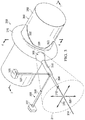
- Figure 3 an illustration of a perspective view of a radiation generation system is depicted in accordance with an illustrative embodiment.
- radiation generation system 300 is an example of one implementation for radiation generation system 212 in Figure 2 .
- radiation generation system 300 comprises radiation source 302, collimator 304, bearing system 306, and movement system 308.
- Radiation source 302, collimator 304, bearing system 306, and movement system 308 are examples of implementations for radiation source 218, collimator 220, bearing system 221, and movement system 223 in Figure 2 .
- Radiation generation system 300 may be connected to a moveable platform (not shown), such as, for example, moveable platform 210 in Figure 2 .
- radiation source 302 takes the form of x-ray tube 310.
- X-ray tube 310 generates x-rays (not shown) within field of view 311 for x-ray tube 310.
- Collimator 304 filters these x-rays such that only a portion of these x-rays is allowed to exit aperture 312 of collimator 304. The portion of x-rays that exits aperture 312 of collimator 304 forms x-ray beam 314.
- Bearing system 306 connects collimator 304 to x-ray tube 310.
- bearing system 306 comprises first structure 316 and second structure 318.
- first structure 316 has a toroidal-type shape.
- Portion 320 of first structure 316 is comprised of a shielding material, while portion 322 of first structure 316 is comprised of a material that is lighter than a shielding material.
- Second structure 318 is also comprised of this shielding material in this illustrative example.
- Second structure 318 has an elongate shape configured to hold collimator 304. Second structure 318 is moveably connected to first structure 316 in this illustrative example. In particular, second structure 318 is configured to move independently of first structure 316. More specifically, when second structure 318 is moved, first structure 316 remains stationary relative to second structure 318.
- Movement system 308 is configured to move bearing system 306.
- movement system 308 is configured to move second structure 318 of bearing system 306.
- movement system 308 comprises first actuator 324 and second actuator 326.
- First actuator 324 and second actuator 326 may be connected to a moveable platform (not shown) for radiation generation system 300.
- first actuator 324 and second actuator 326 may be connected to the moveable platform by bearing 325 and bearing 327, respectively.
- Bearing 325 and bearing 327 are spherical bearings in this illustrative example.
- first actuator 324 and second actuator 326 may be connected to some other suitable type of structure using bearing 325 and bearing 327, respectively.
- First actuator 324 is configured to lengthen or shorten to rotate second structure 318 around first structure 316 and x-ray tube 310.
- second actuator 326 is configured to lengthen or shorten to rotate second structure 318 around first structure 316 and x-ray tube 310.
- First actuator 324 and second actuator 326 may be operated together.
- first actuator 324 and second actuator 326 may both be lengthened or both be shortened.
- first actuator 324 may be shortened, while second actuator 326 is lengthened.
- first actuator 324 may be lengthened, while second actuator 326 is shortened.
- first actuator 324 and/or second actuator 326 may be operated to rotate second structure 318 such that the location on an object at which x-ray beam 314 is pointed moves in at least one of a direction along axis 328 and a direction along axis 330.
- first actuator 324 and the length of second actuator 326 determines the range of rotation for second structure 318.
- shape and/or size of first structure 316 and second structure 318 may be configured to restrict the range of rotation for second structure 318.
- second structure 318 may be rotated around first structure 316 such that x-ray beam 314 may be directed in any direction within field of view 311 for x-ray tube 310.
- x-ray beam 314 may be directed in any direction within only a portion of field of view 311.
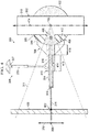
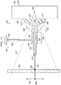
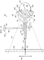
- FIG. 4-6 illustrations of a cross-sectional view of radiation generation system 300 in Figure 3 , taken along lines 4-4 in Figure 3 , are depicted in accordance with an illustrative embodiment.
- First actuator 324 is not seen in the cross-sectional view of radiation generation system 300 in Figures 4-6 .
- x-ray tube 310 generates x-rays 400 and emits x-rays 400 from center point 402 along center axis 404 through x-ray tube 310.
- first structure 316 shares center point 402 with x-ray tube 310.
- first structure 316 and x-ray tube 310 may be substantially concentric to each other.
- first structure 316 has window 406 that allows substantially all of x-rays 400 to pass through first structure 316.
- bearing system 306 provides shielding for the portion of x-rays 400 generated by x-ray tube 310 that do not form x-ray beam 314.
- Second structure 318 is moveably connected to first structure 316 such that second structure 318 may rotate around first structure 316, while first structure 316 remains stationary.
- second structure 318 has first end 408 and second end 410.
- First end 408 has concave spherical shape 412. With this shape, second structure 318 may rotate around first structure 316 in any direction substantially about center point 402.
- second structure 318 has channel 414 that extends through the entire length of second structure 318.
- First portion 416 of channel 414 is smaller than second portion 418 of channel 414.
- Second portion 418 of channel 414 has a size configured to receive and hold collimator 304 at second end 410 of second structure 318.
- second structure 318 of bearing system 306 and collimator 304 are configured such that collimator 304 emits x-ray beam 314. Further, the size of aperture 312 and/or the length of collimator 304 may be changed to adjust x-ray beam 314.
- radiation generation system 300 emits x-ray beam 314 toward object 420 to perform inspection of object 420.
- object 420 may be a portion of a fuselage of an aircraft.
- x-ray beam 314 is pointed at location 422 on object 420.
- Location 422 on object 420 at which x-ray beam 314 is pointed may be moved by at least one of operating movement system 308 and moving the moveable platform (not shown) to which radiation generation system 300 is connected.
- second actuator 326 and/or first actuator 324 in Figure 3 may be each lengthened or shortened to rotate second structure 318 around first structure 316 and x-ray tube 310 about center point 402 such that location 422 on object 420 at which x-ray beam 314 is pointed moves in a direction along axis 330.
- movement system 308 has been operated such that location 422 on object 420 at which x-ray beam 314 was pointed in Figure 4 has been moved in the direction of arrow 500 to location 501.
- second structure 318 has been rotated about center point 402 in the direction of arrow 502 to change the direction in which x-ray beam 314 is pointing.
- x-ray beam 314 is pointing in a direction at the furthest extent of field of view 311. Further, bearing system 306 provides shielding for the portion of x-rays 400 generated by x-ray tube 310 that do not form x-ray beam 314 even after rotation of second structure 318 in the direction of arrow 502.
- movement system 308 has been operated such that location 422 on object 420 at which x-ray beam 314 is pointed in Figure 4 has been moved in the direction of arrow 600 to location 601.
- second structure 318 has been rotated about center point 402 in the direction of arrow 602 to change the direction in which x-ray beam 314 is pointing.
- x-ray beam 314 is pointing in a direction at the furthest extent of field of view 311. Further, bearing system 306 provides shielding for the portion of x-rays 400 generated by x-ray tube 310 that do not form x-ray beam 314 even after rotation of second structure 318 in the direction of arrow 602.
- FIG. 7-9 illustrations of a cross-sectional view of radiation generation system 300 in Figure 3 , taken along lines 7-7 in Figure 3 , are depicted in accordance with an illustrative embodiment.
- Second actuator 326 is not seen in the cross-sectional view of radiation generation system 300 in Figures 7-9 .
- x-ray tube 310 generates x-rays 400 and emits x-rays 400 from center point 402.
- x-ray beam 314 is pointed at location 700 on object 420.
- movement system 308 has been operated such that location 700 on object 420 at which x-ray beam 314 is pointed in Figure 7 has been moved in the direction of arrow 800 to location 801.
- second structure 318 has been rotated about center point 402 in the direction of arrow 802 to change the direction in which x-ray beam 314 is pointing.
- x-ray beam 314 is pointing in a direction at the furthest extent of field of view 311. Further, bearing system 306 provides shielding for the portion of x-rays 400 generated by x-ray tube 310 that do not form x-ray beam 314 even after rotation of second structure 318 in the direction of arrow 802.
- movement system 308 has been operated such that location 700 on object 420 at which x-ray beam 314 is pointed in Figure 7 has been moved in the direction of arrow 900 to location 901.
- second structure 318 has been rotated about center point 402 in the direction of arrow 902 to change the direction in which x-ray beam 314 is pointing.
- x-ray beam 314 is pointing in a direction at the furthest extent of field of view 311. Further, bearing system 306 provides shielding for the portion of x-rays 400 generated by x-ray tube 310 that do not form x-ray beam 314 even after rotation of second structure 318 in the direction of arrow 902.
- first structure 316 of bearing system 306 only has first portion 322.
- Second portion 322 of bearing system 306 in Figures 3-9 has been removed from first structure 316 of bearing system 306. In this manner, the weight and/or cost of bearing system 306 may be reduced.
- Fastener system 1000 is used to attach first structure 316 to x-ray tube 310 in this illustrative example. As depicted, fastener system 1000 comprises fastening device 1002 and fastening device 1004.
- FIG. 11 an illustration of a cross-sectional view of radiation generation system 300 in Figure 10 taken along lines 11-11 is depicted in accordance with an illustrative embodiment. As depicted, bearing system 306 does not wrap around all of x-ray tube 310.
- FIG. 12 an illustration of a cross-sectional view of radiation generation system 300 in Figure 10 taken along lines 12-12 is depicted in accordance with an illustrative embodiment.
- fastener system 1000 is depicted attaching first structure 316 to x-ray tube 310, some other type of fastener system may be used, depending on the implementation.
- FIG. 13 an illustration of a process for steering a beam emitted by a radiation generation system in the form of a flowchart is depicted showing some steps of an illustrative embodiment.
- the process illustrated in Figure 13 may be implemented in inspection environment 200 in Figure 2 .
- the process may be implemented using radiation generation system 212 in backscatter inspection system 202 in Figure 2 .
- the process begins by emitting radiation from a center point in a radiation source (operation 1700 ). Thereafter, a beam is formed from a portion of the radiation emitted by the radiation source using a collimator connected to the radiation source by a bearing system in which the bearing system comprises a first structure and a second structure (operation 1702 ).
- the first structure of the bearing system is connected with the radiation source and the second structure of the bearing system is connected to the first structure.
- the second structure is also configured to hold the collimator.
- a movement system is used to move the second structure of the bearing system such that the second structure rotates in one of a plurality of directions substantially about the center point in the radiation source while the radiation source remains stationary relative to the second structure of the bearing system (operation 1704 ), with the process terminating thereafter.
- Rotation of the second structure substantially about the center point in the radiation source changes a direction in which the beam formed by the collimator is directed.
- the movement system, the bearing system, the collimator, and the radiation source form a radiation generation system for a backscatter inspection system.
- the second structure is moveably connected to the first structure, the first structure remains stationary relative to the second structure when the second structure rotates substantially about the center point in the radiation source.
- Operation 1704 may be performed any number of times while inspecting an object to move the beam along an object in a selected pattern.
- each block in the flowcharts or block diagrams may represent a module, segment, function, and/or a portion of an operation or step.
- one or more of the blocks may be implemented as program code, in hardware, or a combination of the program code and hardware.
- the hardware may, for example, take the form of integrated circuits that are manufactured or configured to perform one or more operations in the flowcharts or block diagrams.
- the function or functions noted in the blocks may occur out of the order noted in the figures.
- two blocks shown in succession may be executed substantially concurrently, or the blocks may sometimes be performed in the reverse order, depending upon the functionality involved.
- other blocks may be added in addition to the illustrated blocks in a flowchart or block diagram.
- aircraft manufacturing and service method 1800 may be described in the context of aircraft manufacturing and service method 1800 as shown in Figure 14 and aircraft 1900 as shown in Figure 15 .
- Figure 14 an illustration of an aircraft manufacturing and service method is depicted.
- aircraft manufacturing and service method 1800 may include specification and design 1802 of aircraft 1900 in Figure 15 and material procurement 1804.
- aircraft 1900 in Figure 15 During production, component and subassembly manufacturing 1806 and system integration 1808 of aircraft 1900 in Figure 15 takes place. Thereafter, aircraft 1900 in Figure 15 may go through certification and delivery 1810 in order to be placed in service 1812. While in service 1812 by a customer, aircraft 1900 in Figure 15 is scheduled for routine maintenance and service 1814, which may include modification, reconfiguration, refurbishment, and other maintenance or service.
- Each of the processes of aircraft manufacturing and service method 1800 may be performed or carried out by a system integrator, a third party, and/or an operator.
- the operator may be a customer.
- a system integrator may include, without limitation, any number of aircraft manufacturers and major-system subcontractors
- a third party may include, without limitation, any number of vendors, subcontractors, and suppliers
- an operator may be an airline, a leasing company, a military entity, a service organization, and so on.
- aircraft 1900 is produced by aircraft manufacturing and service method 1800 in Figure 14 and may include airframe 1902 with plurality of systems 1904 and interior 1906.
- systems 1904 include one or more of propulsion system 1908, electrical system 1910, hydraulic system 1912, and environmental system 1914. Any number of other systems may be included.
- Apparatuses and methods embodied herein may be employed during at least one of the stages of aircraft manufacturing and service method 1800 in Figure 14 .
- backscatter inspection system 202 in Figure 2 may be used to inspect aircraft 1900, a portion of aircraft 1900, or a particular part for aircraft 1900 during component and subassembly manufacturing 1806, system integration 1808, certification and delivery 1810, in service 1812, and/or maintenance and service 1814.
- components or subassemblies produced in component and subassembly manufacturing 1806 in Figure 14 may be fabricated or manufactured in a manner similar to components or subassemblies produced while aircraft 1900 is in service 1812 in Figure 14 .
- one or more apparatus embodiments, method embodiments, or a combination thereof may be utilized during production stages, such as component and subassembly manufacturing 1806 and system integration 1808 in Figure 14 .
- One or more apparatus embodiments, method embodiments, or a combination thereof may be utilized while aircraft 1900 is in service 1812 and/or during maintenance and service 1814 in Figure 14 .
- the use of a number of the different illustrative embodiments may substantially expedite the assembly of and/or reduce the cost of aircraft 1900.
- one or more illustrative embodiments may be used to inspect objects in which an inconsistency may be present.
- a backscatter inspection system may be made smaller and lighter and may fit more easily into enclosed spaces as compared to currently used backscatter inspection systems.
- inspections of aircrafts may be made with less disassembly, time, and cost.
Landscapes
- Physics & Mathematics (AREA)
- Chemical & Material Sciences (AREA)
- Spectroscopy & Molecular Physics (AREA)
- High Energy & Nuclear Physics (AREA)
- General Engineering & Computer Science (AREA)
- Engineering & Computer Science (AREA)
- Life Sciences & Earth Sciences (AREA)
- General Health & Medical Sciences (AREA)
- General Physics & Mathematics (AREA)
- Immunology (AREA)
- Pathology (AREA)
- Biochemistry (AREA)
- Analytical Chemistry (AREA)
- Health & Medical Sciences (AREA)
- Crystallography & Structural Chemistry (AREA)
- Analysing Materials By The Use Of Radiation (AREA)
Description
- The present disclosure relates generally to inspection systems and, in particular, to an aircraft backscatter inspection apparatus. Still more particularly, the present disclosure relates to a method and apparatus for inspecting an object by moving a beam of radiation along the object in a selected pattern and detecting the backscatter formed in response to the beam encountering the object.
-
JP H05 309143 A US 5278886 A discloses a radiosurgery including a collimator adapted movably to an irradiation head.US 2497755 discloses an X-ray tube with movable directing cone andUS 2001/0016028 A1 relates to an X-ray inspection using co-planar pencil and fan beams. - Some currently available nondestructive inspection systems use radiation to inspect an object. The radiation may take the form of, for example, without limitation, x-rays, gamma rays, neutrons, or some other suitable type of radiation. A backscatter x-ray system is one example of a nondestructive inspection system that uses x-rays to inspect an object.
- Some currently available backscatter x-ray systems include an x-ray tube, a collimator, and a detector system. The x-ray tube generates and emits x-rays. The collimator filters these x-rays to form an x-ray beam using the portion of the x-rays that travels parallel to a specified direction. This x-ray beam may be referred to as a pencil x-ray beam in some cases. During inspection of an object, the collimator is positioned such that the x-ray beam is directed toward the object.
- When the x-ray beam encounters the object, some or all of the x-rays in the x-ray beam are scattered by the object. These scattered x-rays are referred to as backscatter. The detector system detects some or all of this backscatter. The detected backscatter may be used to generate image data for the object that can be used to form one or more images of the object. For example, the backscatter detected when the x-ray beam is directed at a particular location on the object may be used to generate a value for a pixel in an image that corresponds to that particular location on the object.
- The x-ray beam may be moved along the object in a selected pattern such that image data may be generated for different locations on the object. This pattern may be, for example, a raster pattern. In particular, the x-ray beam may be oscillated along the object. Oscillating an x-ray beam includes moving the x-ray beam back and forth in a particular direction. The backscatter x-ray system may be mounted on a moveable platform that moves the backscatter x-ray system such that the x-ray beam may be oscillated in different directions substantially parallel to each other. The image data may then be used to form one or more images of the object. These images may be used to determine whether any inconsistencies are present in the object.
- With some currently available backscatter x-ray systems, oscillating an x-ray beam along the object requires moving both the x-ray tube and the collimator at the same time independently of the moveable platform. In other words, moving the x-ray beam from one location on the object to another location on the object requires that both the collimator and the x-ray tube be moved. The number of components needed to move both the x-ray tube and the collimator such that the x-ray beam may be moved along the object in a selected pattern may be greater than desired with these currently available backscatter x-ray systems. Further, the weight and/or complexity of these types of backscatter x-ray systems may be greater than desired.
- Therefore, it would be desirable to have a method and apparatus that takes into account at least some of the issues discussed above, as well as other possible issues.
- According thereto, an apparatus is provided as defined in
claim 1. The apparatus comprises i.a. a radiation source, a collimator, a bearing system, and a movement system. The radiation source is configured to emit radiation. The collimator is configured to form a beam using a portion of the radiation emitted by the radiation source. The bearing system is configured to connect the collimator to the radiation source. The bearing system comprises a first structure connected with the radiation source and a second structure connected to the first structure. The second structure is configured to hold the collimator. The movement system is configured to move the second structure of the bearing system such that the second structure rotates in one of a plurality of directions substantially about a center point in the radiation source while the radiation source remains stationary relative to the second structure. Rotation of the second structure substantially about the center point changes a direction in which the beam formed by the collimator is directed. Furthermore, a method for inspecting, using the system ofclaim 1, is provided as defined in claim 9. In the method, i.a., radiation is emitted from the radiation source. The beam is formed from a portion of the radiation emitted by the radiation source using the collimator. The collimator is connected to the radiation source by the bearing system comprising the first structure connected with the radiation source and the second structure connected to the first structure. The second structure is configured to hold the collimator. The second structure of the bearing system is moved using the movement system such that the second structure rotates in one of a plurality of directions substantially about the center point in the radiation source while the radiation source remains stationary relative to the second structure. Rotation of the second structure substantially about the center point in the radiation source changes a direction in which the beam is directed. - Preferably the first structure has a toroidal-type shape. The bearing system is configured to move independently of the radiation source such that the radiation source remains stationary relative to the second structure when the second structure rotates substantially about the center point.
- The apparatus comprises:
- a detector system configured to detect backscatter formed in response to the beam encountering an object and generate data in response to detecting the backscatter.
- Preferably, the apparatus further comprises:
- a computer system in communication with the detector system, wherein the computer system is configured to receive the data and generate a number of images of the object using the data in which the number of images is used to detect an inconsistency in the object. The radiation source, the collimator, the bearing system, and the movement system form a radiation generation system in a backscatter (246) inspection system, which system preferably further comprises :
- a moveable platform, wherein the radiation generation system is connected to the moveable platform. Further details can be seen with reference to the following description and drawings.
- The illustrative embodiments, as well as a preferred mode of use, further objectives and features thereof, will best be understood by reference to the following detailed description of an illustrative embodiment of the present disclosure when read in conjunction with the accompanying drawings, wherein:
-
Figure 1 is an illustration of an x-ray inspection environment in accordance with an illustrative embodiment; -
Figure 2 is an illustration of an inspection environment in the form of a block diagram in accordance with an illustrative embodiment; -
Figure 3 is an illustration of a perspective view of a radiation generation system in accordance with an illustrative embodiment; -
Figure 4 is an illustration of a cross-sectional view of a radiation generation system in accordance with an illustrative embodiment; -
Figure 5 is an illustration of a cross-sectional view of a radiation generation system in accordance with an illustrative embodiment; -
Figure 6 is an illustration of a cross-sectional view of a radiation generation system in accordance with an illustrative embodiment; -
Figure 7 is an illustration of a cross-sectional view of a radiation generation system in accordance with an illustrative embodiment; -
Figure 8 is an illustration of a cross-sectional view of a radiation generation system in accordance with an illustrative embodiment; -
Figure 9 is an illustration of a cross-sectional view of a radiation generation system in accordance with an illustrative embodiment; -
Figure 10 is an illustration of a configuration for a bearing system in a radiation generation system in accordance with an illustrative embodiment; -
Figure 11 is an illustration of a cross-sectional view of a radiation generation system in accordance with an illustrative embodiment; -
Figure 12 is an illustration of a cross-sectional view of a radiation generation system in accordance with an illustrative embodiment; -
Figure 13 is an illustration of a process for steering a beam emitted by a radiation generation system, in the form of a flowchart, in accordance with some steps of an illustrative embodiment; -
Figure 14 is an illustration of an aircraft manufacturing and service method; and -
Figure 15 is an illustration of an aircraft in which an illustrative embodiment may be implemented. - The illustrative embodiments recognize and take into account one or more different considerations. For example, the different illustrative embodiments recognize and take into account that some currently available backscatter x-ray systems weigh more than desired. This increased weight may prevent these backscatter x-ray systems from being used in certain locations or used to inspect certain types of objects.
- Further, the different illustrative embodiments recognize and take into account that the increased weight of these backscatter x-ray systems may be attributed to the shielding materials used in these backscatter x-ray systems. Shielding materials are materials used to provide protection from radiation, such as, for example, x-rays. These shielding materials may absorb and/or scatter x-rays such that the x-rays are not allowed to pass through the shielding materials.
- With some currently available backscatter x-ray systems, shielding material may be required to fully wrap around the x-ray tube. The different illustrative embodiments recognize and take into account that by reducing the amount of shielding material used around an x-ray tube, the weight of a backscatter x-ray system may be reduced.
- Additionally, the different illustrative embodiments recognize and take into account that an x-ray source that is moving relative to the moveable platform on which the backscatter x-ray system is mounted during operation of the x-ray source may have a shorter life expectancy than an x-ray source that remains stationary relative to the moveable platform. In particular, high frequency motion and oscillation of the x-ray source may reduce the life expectancy of the x-ray source.
- Thus, the invention provides a method and apparatus as claimed in the independent claims. With reference now to the figures and, in particular, with reference to
Figure 1 , an illustration of an x-ray inspection environment is depicted in accordance with an illustrative embodiment. In this depicted example,x-ray inspection environment 100 includesaircraft 102 andbackscatter x-ray system 104. In this illustrative example,backscatter x-ray system 104 is configured to inspect an object, such as, for example,fuselage 108 ofaircraft 102. In particular,backscatter x-ray system 104 is used to inspectsection 106 offuselage 108 ofaircraft 102 in this depicted example. -
Backscatter x-ray system 104 may be positioned outside offuselage 108 or inside offuselage 108 to inspectsection 106 offuselage 108. In one illustrative example,backscatter x-ray system 104 is placed insidesection 106 offuselage 108 and configured to move withinfuselage 108 to inspectsection 106 offuselage 108. - In particular,
backscatter x-ray system 104 is configured to emit a single x-ray beam that is moved alongsection 106 in a selected pattern asbackscatter x-ray system 104 moves withinfuselage 108. For example, the x-ray beam may be directed at a location onsection 106 offuselage 108 and then moved or steered to scansection 106 offuselage 108 in a selected pattern. - This x-ray beam may penetrate through at least a portion of the thickness of
section 106 offuselage 108 at the location at which the x-ray beam is directed. As used herein, "at least a portion" of an item or a plurality of items may be some or all of the items or plurality of items. For example, at least a portion of the thickness ofsection 106 may be some of this thickness or the entire thickness. In this illustrative example, the x-ray beam penetrates through the entire thickness ofsection 106 at the location at which the x-ray beam is directed. - When
backscatter x-ray system 104 is located insidefuselage 108, a portion of the x-rays in the x-ray beam that encountersection 106 offuselage 108 are scattered bysection 106 offuselage 108. These scattered x-rays are referred to as backscatter x-rays or backscatter. - In this illustrative example,
backscatter x-ray system 104 is configured to detect this backscatter and use the detected backscatter to generate images ofsection 106 offuselage 108. These images may be used as part of the inspection process to determine whether one or more inconsistencies are present insection 106 offuselage 108. In particular, these images may be used to determine whether one or more inconsistencies are present on an interior surface ofsection 106, on an exterior surface ofsection 106, and/or between the interior surface and the exterior surface ofsection 106. - As depicted, the images generated by
backscatter x-ray system 104 may be sent tocomputer system 110 over wireless communications link 112.Computer system 110 may process these images to determine whether one or more inconsistencies are present insection 106 offuselage 108. Although wireless communications link 112 is used for communications betweencomputer system 110 andbackscatter x-ray system 104 in this depicted example, a wired communications link, an optical communications link, or some other suitable type of communications link may be used in other illustrative examples. - With reference now to
Figure 2 , an illustration of an inspection environment in the form of a block diagram is depicted in accordance with an illustrative embodiment.X-ray inspection environment 100 inFigure 1 is an example of one implementation forinspection environment 200 inFigure 2 . - In these illustrative examples,
inspection environment 200 includesbackscatter inspection system 202,computer system 203, andobject 204.Backscatter inspection system 202 one example for nondestructive inspection (NDI)system 206. As used herein, a "nondestructive inspection system," such asnondestructive inspection system 206, is a system configured to inspect an object, such asobject 204, without causing any undesired effects to the object. In particular, a nondestructive inspection system is configured to inspect an object without causing any physical alterations on the object. -
Nondestructive inspection system 206 may also be referred to as a nondestructive evaluation (NDE) system, a nondestructive testing (NDT) system, or a nondestructive examination (NDE) system.Backscatter x-ray system 104 inFigure 1 is an example of one implementation fornondestructive inspection system 206 inFigure 2 . - In these illustrative examples,
backscatter inspection system 202 may be used to inspectobject 204. - In some cases, object 204 may be a part in another object. For example, in some cases, object 204 may be a section of a fuselage for an aircraft, a wing, a fuel tank, or some other suitable type of part.
-
Backscatter inspection system 202 generatesdata 207 forobject 204 during inspection ofobject 204.Data 207 may include, for example, without limitation,image data 208 forobject 204. Further,backscatter inspection system 202 sendsdata 207 tocomputer system 203.Computer system 203 is configured to receive andprocess data 207 generated bybackscatter inspection system 202.Backscatter inspection system 202 includesmoveable platform 210,radiation generation system 212, anddetector system 214. In this illustrative example,radiation generation system 212 anddetector system 214 are connected tomoveable platform 210. - As used herein, a first component "connected to" a second component means that the first component can be connected directly or indirectly to the second component. In other words, additional components may be present between the first component and the second component. The first component is considered to be indirectly connected to the second component when one or more additional components are present between the two components. When the first component is directly connected to the second component, no additional components are present between the two components.
-
Moveable platform 210 may be any platform configured to move over a surface. This movement may include translation and/or rotation.Moveable platform 210 may take various forms depending on the particular implementation. In one illustrative example,moveable platform 210 may be a cart. -
Moveable platform 210 may include movement devices such as, for example, without limitation, wheels, rollers, sliders, a track system, and other types of movement devices. These movement devices may allowmoveable platform 210 to move or be moved on a surface, such as, for example, without limitation, a floor, a rail system, or some other suitable type of surface. - In one illustrative example,
moveable platform 210 may be moved by a human operator pushingmoveable platform 210. In another illustrative example,moveable platform 210 may be moved using a propulsion system inmoveable platform 210.Radiation generation system 212 comprisesradiation source 218,collimator 220,bearing system 221, andmovement system 223.Radiation source 218 is configured to generateradiation 222.Radiation 222 comprises a plurality of rays. - In one illustrative example,
radiation source 218 takes the form of an x-ray tube configured to generate and emitx-rays 224. This x-ray tube may have a cylindrical shape. -
Radiation source 218 emitsradiation 222 from a point withinradiation source 218. In one illustrative example,radiation source 218 may emitradiation 222 radially fromcenter point 228 inradiation source 218.Center point 228 may be a point along a center axis throughradiation source 218. Whenradiation source 218 has a cylindrical shape,center point 228 may be any point along a center axis along the length of the cylindrical shape. Of course, in other illustrative examples,center point 228 may be any point within an interior ofradiation source 218. In some illustrative examples,radiation source 218 may emitradiation 222 from a point withinradiation source 218 other thancenter point 228. -
Radiation 222 is emitted byradiation source 218 within field of view (FOV) 230. As used herein, a "field of view" (FOV) for a radiation source, such as field ofview 230 forradiation source 218, is the horizontal extent and vertical extent to whichradiation 222 is emitted. In these illustrative examples, field ofview 230 may be described using degrees in a horizontal direction and degrees in a vertical direction with respect toradiation source 218. - In these illustrative emodiments,
collimator 220 is a device that filters the plurality of rays inradiation 222 such that only the portion of rays traveling parallel to a specified direction are allowed to pass throughcollimator 220. This specified direction may be the direction along a center axis throughguide 232 incollimator 220.Guide 232 is a channel withincollimator 220 through which rays may pass. In particular,collimator 220 may absorb a portion of the rays inradiation 222, scatter a portion of the rays inradiation 222, or perform a combination of the two such that only rays that travel in the direction of the center axis throughguide 232 may pass throughcollimator 220. - A portion of
radiation 222 that passes throughguide 232 incollimator 220 exits collimator 220 ataperture 233 in the form ofbeam 234.Beam 234 may comprise one or more rays of radiation.Aperture 233 is an opening incollimator 220 at the end ofguide 232.Beam 234 may exitaperture 233 in a direction towardobject 204. In this manner,collimator 220 is configured to filter the rays inradiation 222 to form and emitbeam 234. As in the claimed apparatus and method,radiation 222 takes the form ofx-rays 224,beam 234 is referred to as an x-ray beam. - In some illustrative examples,
collimator 220 may be configured to change the size ofaperture 233 and/or the length ofguide 232 incollimator 220. Changing the length ofguide 232 may change the field intensity and/or beam dispersion ofbeam 234. For example, increasing the length ofguide 232 decreases field intensity and decreases beam dispersion. Changing the size ofaperture 233 changes the spot size ofbeam 234 onobject 204. -
Collimator 220 is moveably connected toradiation source 218 usingbearing system 221 associated withcollimator 220. When one component is "associated" with another component, the association is a physical association in these depicted examples. For example, a first component may be considered to be associated with a second component by being secured to the second component, bonded to the second component, mounted to the second component, welded to the second component, fastened to the second component, and/or connected to the second component in some other suitable manner. - The first component also may be connected to the second component using a third component. Additionally, the first component may be considered to be associated with the second component by being formed as part of and/or an extension of the second component.
Bearing system 221 comprises components that moveably connectcollimator 220 toradiation source 218 in a manner that allowscollimator 220 to move independently ofradiation source 218.Bearing system 221 allowscollimator 220 to move aroundradiation source 218, whileradiation source 218 remains stationary relative tocollimator 220.Bearing system 221 comprisesfirst structure 236 andsecond structure 238.First structure 236 is connected withradiation source 218. - In these illustrative examples,
first structure 236 may be a structure that is connected withradiation source 218 by wrapping around at least a portion ofradiation source 218. In one illustrative example,first structure 236 has a toroidal-type shape that surrounds the portion ofradiation source 218 from whichradiation 222 is emitted. A toroidal-type shape is a ring-type shape with a hollow center portion. - In this illustrative example, the hollow center portion of
first structure 236 may substantially conform to the curved shape ofradiation source 218 such thatfirst structure 236 wraps aroundradiation source 218. In some cases,center point 228 ofradiation source 218 may also be a center point forfirst structure 236. - In another illustrative example,
first structure 236 may only be a section of a toroidal-type shape. For example,first structure 236 may have an arc-type shape that substantially conforms to the curved shape of a portion ofradiation source 218. - In these illustrative examples,
first structure 236 haswindow 240 through which at least a portion ofradiation 222 is allowed to pass without being scattered, absorbed, or a combination of the two. When all ofradiation 222 is allowed to pass throughwindow 240,window 240 may have a size and shape selected based on field ofview 230 forradiation source 218. - Further, in these examples,
window 240 may be comprised of a material that allowsradiation 222 to pass throughwindow 240 without any ofradiation 222 being scattered and/or absorbed. However, in some cases,window 240 may be an opening infirst structure 236. For example,window 240 may take the form of an open channel. - As depicted,
second structure 238 hasfirst end 242 andsecond end 243.Second structure 238 has a concave spherical shape atfirst end 242 ofsecond structure 238 and an elongate shape atsecond end 243 ofsecond structure 238. Further,second structure 238 haschannel 244 that runs along a center axis throughsecond structure 238.Channel 244 extends fromfirst end 242 tosecond end 243 ofsecond structure 238. - The size and/or shape of
channel 244 may change along the length ofsecond structure 238, depending on the implementation. For example, the portion ofchannel 244 atsecond end 243 ofsecond structure 238 may be configured to receive and hold at least a portion ofcollimator 220 withinchannel 244. - In these illustrative examples, a portion of the rays in
radiation 222 that pass throughwindow 240 infirst structure 236 pass throughchannel 244 insecond structure 238. Further, a portion of the rays that pass throughchannel 244 insecond structure 238, encounter the opening intoguide 232 ofcollimator 220, and travel in a direction substantially parallel to a center axis throughguide 232 may pass throughguide 232. A portion of the rays that pass throughguide 232 exitsaperture 233 in the form ofbeam 234. - In these illustrative examples, at least a portion of
first structure 236 andsecond structure 238 comprises shieldingmaterial 235.Shielding material 235 is configured to scatter and/or absorbradiation 222 such thatradiation 222 does not pass through shieldingmaterial 235. In particular, shieldingmaterial 235 is configured to protect the environment outside ofradiation generation system 212 from any portion ofradiation 222 that is not used to formbeam 234.Shielding material 235 may comprise, for example, without limitation, at least one of lead, tungsten, brass, and some other suitable type of shielding material. - As used herein, the phrase "at least one of", when used with a list of items, means different combinations of one or more of the listed items may be used and only one of each item in the list may be needed. For example, "at least one of item A, item B, and item C" may include, without limitation, item A or item A and item B. This example also may include item A, item B, and item C, or item B and item C. In other examples, "at least one of" may be, for example, without limitation, two of item A, one of item B, and ten of item C; four of item B and seven of item C; or some other suitable combination.
-
Second structure 238 is moveably connected tofirst structure 236.First structure 236 remains stationary relative tosecond structure 238 whensecond structure 238 moves. -
Bearing system 221 is configured to allowsecond structure 238 to rotate substantially aboutcenter point 228 inradiation source 218. Depending on the implementation,center point 228 about whichsecond structure 238 is rotated may or may not be the same point withinradiation source 218 from whichradiation 222 is emitted.Bearing system 221 allowssecond structure 238 to rotate substantially in one of a plurality of directions aboutcenter point 228 Assecond structure 238 is moveably connected tofirst structure 236,first structure 236 remains stationary whilesecond structure 238 is rotated substantially aboutcenter point 228 aroundfirst structure 236. In this manner, bearingsystem 221 is always configured to allowsecond structure 238 to rotate substantially aboutcenter point 228. However,bearing system 221 is configured to restrict the number of degrees by whichsecond structure 238 may be rotated substantially aboutcenter point 228. - As one illustrative example,
second structure 238 may be rotated in any direction substantially aboutcenter point 228 but within a selected range of degrees. This selected range of degrees may be less than about 360 degrees. In some cases, this selected range may be less than about 180 degrees. -
Movement system 223 is configured to movebearing system 221 and to movesecond structure 238 such thatsecond structure 238 rotates aroundradiation source 218 substantially aboutcenter point 228. This movement ofsecond structure 238 causescollimator 220 held bysecond structure 238 to also rotate. Whencollimator 220 moves,beam 234 moves. -
Movement system 223 may also be used to restrict the movement ofsecond structure 238. In one illustrative example,bearing system 221 andmovement system 223 may be configured such that rotation ofsecond structure 238 is restricted to within field ofview 230 forradiation source 218. In other words, the extent to whichsecond structure 238 may be rotated in any direction substantially aboutcenter point 228 may not be greater than the extent of field ofview 230 forradiation source 218 in that direction. In this illustrative example,collimator 220 may be rotated such thatbeam 234 may be directed or pointed in any direction within field ofview 230 forradiation source 218. - The movement of
second structure 238 andfirst structure 236 may be restricted such that shieldingmaterial 235 may not be required to wrap around all ofradiation source 218. Rather, shieldingmaterial 235 infirst structure 236 may only be needed around the portion ofradiation source 218 at whichradiation 222 is emitted. - In some illustrative examples, one or more components in
movement system 223 may be connected tomoveable platform 210. Of course, in other illustrative examples, one or more components inmovement system 223 may be connected toradiation source 218. In still other illustrative examples,movement system 223 may be connected to some other structure withinbackscatter inspection system 202. -
Movement system 223 may comprise a number of devices configured to movebearing system 221. For example,movement system 223 may include at least one of an actuator, a gear, a motor, a track system, and/or other suitable types of devices. -
Beam 234 may be directed towardobject 204 to perform inspection ofobject 204. In these illustrative examples,object 204,moveable platform 210, and/orbearing system 221 withcollimator 220 may be moved such thatbeam 234 may be moved alongobject 204 in a selected pattern. This selected pattern may be, for example, a raster pattern, a step pattern, a sinusoidal pattern, or some other suitable type of pattern. - With a raster pattern,
beam 234 may be moved back and forth in a number of directions parallel to each other. In this manner,beam 234 may be moved alongobject 204 such that the rays inbeam 234 penetrate through different locations alongobject 204.Bearing system 221 is configured to move independently ofradiation source 218. In other words,radiation source 218 remains stationary relative to bearingsystem 221 whenmovement system 223 movessecond structure 238 to steerbeam 234. - At each location on
object 204 at whichbeam 234 is directed,beam 234 penetrates through at least a portion ofthickness 248 ofobject 204. At least a portion of the rays inbeam 234 may be scattered whenbeam 234 encounters object 204. For example, these scattered rays may include rays scattered by a surface ofobject 204 and/or scattered by a subsurface portion ofobject 204 beneath the surface ofobject 204. The scattered rays formed bybeam 234 encounteringobject 204form backscatter 246. -
Detector system 214 inbackscatter inspection system 202 is configured to detectbackscatter 246.Detector system 214 may take a number of different forms. For example,detector system 214 may include one or more detectors. A detector indetector system 214 may comprise at least one of, for example, without limitation, a solid state detector, a scintillator detector, and some other suitable type of detector. -
Detector system 214 generatesdata 207 in response to detectingbackscatter 246.Image data 208 indata 207 may include, for example, a value for a pixel corresponding to each of a plurality of locations onobject 204 at whichbeam 234 was directed. -
Detector system 214 sendsdata 207 tocomputer system 203 for processing using communications link 247. Communications link 247 may be a wireless communications link, a wired communications link, an optical communications link, or some other suitable type of communications link. -
Computer system 203 may include one or more computers, depending on the implementation. As used herein, a "number of" when used with reference to items means one or more items. For example, a number of computers is one or more computers. When more than one computer is present incomputer system 203, these computers may be in communication with each other using a medium such as a network. The network may employ wired communications links, wireless communications links, and other suitable types of links for exchanging information. -
Data 207 may be used to determine whetherinconsistency 250 is present inobject 204.Inconsistency 250 may be present at the surface ofobject 204 or within an interior ofobject 204. In one illustrative example,computer system 203 usesdata 207 to form number ofimages 252 ofobject 204. Number ofimages 252 may be analyzed bycomputer system 203 and/or a human operator to detect the presence of, and identify the location of,inconsistency 250 inobject 204. Of course, in other illustrative examples,image data 208 indata 207 generated bydetector system 214 may take the form of number ofimages 252. - Depending on the implementation,
computer system 203 may be configured to control at least one ofradiation generation system 212,moveable platform 210, anddetector system 214. For example,computer system 203 may send commands tomoveable platform 210 and/ormovement system 223 inradiation generation system 212 to control the steering ofbeam 234. In some cases,computer system 203 may send commands toradiation generation system 212 to control the size ofaperture 233 and/or the length ofguide 232 incollimator 220. - The configuration of
radiation source 218,collimator 220,bearing system 221, andmovement system 223 inradiation generation system 212 inFigure 2 provides a radiation generation system with a lower level of complexity as compared to radiation generation systems in some currently used nondestructive inspection systems. Further, withcollimator 220 being moveably connected toradiation source 218 usingbearing system 221,backscatter inspection system 202 may be reduced in size as compared to other currently used backscatter inspection systems. As a result of the reduction in complexity and size,backscatter inspection system 202 may weigh less than currently used backscatter inspection systems. - Thus,
backscatter inspection system 202 may be used to inspect many different locations such as, for example, without limitation, interior locations and other locations that may be hard to reach using currently available backscatter inspection systems. For example, whenobject 204 is a fuel tank in an aircraft,backscatter inspection system 202 may have a size and configuration that allowsbackscatter inspection system 202 to be placed within the fuel tank to inspect the fuel tank from within the fuel tank. - Additionally, the reduced size and weight of
backscatter inspection system 202 may allow an operator to more easily movebackscatter inspection system 202 and/or maneuver aroundbackscatter inspection system 202. Consequently,backscatter inspection system 202 may provide more cost savings for the operator and/or increase the efficiency with which inspections are performed as compared to some currently used x-ray inspections systems. - The illustration of
inspection environment 200 in Figure 2 is not meant to imply physical or architectural limitations to the manner in which an illustrative embodiment may be implemented, beyond of what is required by the independent claims. Other components in addition to or in place of the ones illustrated may be used. Some components, namely those which are not claimed in the independent claims, may be optional. Also, the blocks are presented to illustrate some functional components. One or more of these blocks may be combined, divided, or combined and divided into different blocks when implemented in an illustrative embodiment, as long as this is in line with the subject matter defined in the independent claims. In some illustrative examples,moveable platform 210 may take the form of a housing or unit in whichradiation generation system 212 anddetector system 214 may be placed. This housing system may be moveable by a robotic arm or some other system. In some illustrative examples,computer system 203 may be considered part ofbackscatter inspection system 202 and/or located onmoveable platform 210. - In one illustrative example,
computer system 203 may analyzedata 207 and generate an identification ofinconsistency 250 wheninconsistency 250 is detected on the surface ofobject 204. In another illustrative example,bearing system 221 andcollimator 220 both may be considered part of a collimator assembly. In some cases,first structure 236 of bearingsystem 221 may be referred to as a collar or a collimator collar. With reference now toFigure 3 , an illustration of a perspective view of a radiation generation system is depicted in accordance with an illustrative embodiment. In this illustrative embodiment,radiation generation system 300 is an example of one implementation forradiation generation system 212 inFigure 2 . - As depicted,
radiation generation system 300 comprisesradiation source 302,collimator 304,bearing system 306, andmovement system 308.Radiation source 302,collimator 304,bearing system 306, andmovement system 308 are examples of implementations forradiation source 218,collimator 220,bearing system 221, andmovement system 223 inFigure 2 .Radiation generation system 300 may be connected to a moveable platform (not shown), such as, for example,moveable platform 210 inFigure 2 . - In this illustrative example,
radiation source 302 takes the form ofx-ray tube 310.X-ray tube 310 generates x-rays (not shown) within field ofview 311 forx-ray tube 310.Collimator 304 filters these x-rays such that only a portion of these x-rays is allowed to exitaperture 312 ofcollimator 304. The portion of x-rays that exitsaperture 312 ofcollimator 304forms x-ray beam 314. -
Bearing system 306 connectscollimator 304 tox-ray tube 310. As depicted,bearing system 306 comprisesfirst structure 316 andsecond structure 318. In this illustrative example,first structure 316 has a toroidal-type shape.Portion 320 offirst structure 316 is comprised of a shielding material, whileportion 322 offirst structure 316 is comprised of a material that is lighter than a shielding material.Second structure 318 is also comprised of this shielding material in this illustrative example. -
Second structure 318 has an elongate shape configured to holdcollimator 304.Second structure 318 is moveably connected tofirst structure 316 in this illustrative example. In particular,second structure 318 is configured to move independently offirst structure 316. More specifically, whensecond structure 318 is moved,first structure 316 remains stationary relative tosecond structure 318. -
Movement system 308 is configured to movebearing system 306. In particular,movement system 308 is configured to movesecond structure 318 of bearingsystem 306. In this illustrative example,movement system 308 comprisesfirst actuator 324 andsecond actuator 326.First actuator 324 andsecond actuator 326 may be connected to a moveable platform (not shown) forradiation generation system 300. - For example,
first actuator 324 andsecond actuator 326 may be connected to the moveable platform by bearing 325 andbearing 327, respectively.Bearing 325 and bearing 327 are spherical bearings in this illustrative example. Of course, in other illustrative examples,first actuator 324 andsecond actuator 326 may be connected to some other suitable type ofstructure using bearing 325 andbearing 327, respectively. -
First actuator 324 is configured to lengthen or shorten to rotatesecond structure 318 aroundfirst structure 316 andx-ray tube 310. Similarly,second actuator 326 is configured to lengthen or shorten to rotatesecond structure 318 aroundfirst structure 316 andx-ray tube 310. -
First actuator 324 andsecond actuator 326 may be operated together. For example,first actuator 324 andsecond actuator 326 may both be lengthened or both be shortened. Further, in some cases,first actuator 324 may be shortened, whilesecond actuator 326 is lengthened. In other cases,first actuator 324 may be lengthened, whilesecond actuator 326 is shortened. In particular,first actuator 324 and/orsecond actuator 326 may be operated to rotatesecond structure 318 such that the location on an object at whichx-ray beam 314 is pointed moves in at least one of a direction alongaxis 328 and a direction alongaxis 330. - The extent to which the length of
first actuator 324 and the length ofsecond actuator 326 can be changed determines the range of rotation forsecond structure 318. Further, the shape and/or size offirst structure 316 andsecond structure 318 may be configured to restrict the range of rotation forsecond structure 318. In this illustrative example,second structure 318 may be rotated aroundfirst structure 316 such thatx-ray beam 314 may be directed in any direction within field ofview 311 forx-ray tube 310. In other illustrative examples,x-ray beam 314 may be directed in any direction within only a portion of field ofview 311. - With reference now to
Figures 4-6 , illustrations of a cross-sectional view ofradiation generation system 300 inFigure 3 , taken along lines 4-4 inFigure 3 , are depicted in accordance with an illustrative embodiment.First actuator 324 is not seen in the cross-sectional view ofradiation generation system 300 inFigures 4-6 . - Turning now to
Figure 4 ,x-ray tube 310 generatesx-rays 400 and emitsx-rays 400 fromcenter point 402 alongcenter axis 404 throughx-ray tube 310. In this illustrative example,first structure 316shares center point 402 withx-ray tube 310. In other words,first structure 316 andx-ray tube 310 may be substantially concentric to each other. - Further,
first structure 316 haswindow 406 that allows substantially all ofx-rays 400 to pass throughfirst structure 316. As depicted,bearing system 306 provides shielding for the portion ofx-rays 400 generated byx-ray tube 310 that do not formx-ray beam 314. -
Second structure 318 is moveably connected tofirst structure 316 such thatsecond structure 318 may rotate aroundfirst structure 316, whilefirst structure 316 remains stationary. For example,second structure 318 hasfirst end 408 andsecond end 410.First end 408 has concavespherical shape 412. With this shape,second structure 318 may rotate aroundfirst structure 316 in any direction substantially aboutcenter point 402. - Additionally,
second structure 318 haschannel 414 that extends through the entire length ofsecond structure 318.First portion 416 ofchannel 414 is smaller thansecond portion 418 ofchannel 414.Second portion 418 ofchannel 414 has a size configured to receive and holdcollimator 304 atsecond end 410 ofsecond structure 318. - In this illustrative example,
second structure 318 of bearingsystem 306 andcollimator 304 are configured such thatcollimator 304 emitsx-ray beam 314. Further, the size ofaperture 312 and/or the length ofcollimator 304 may be changed to adjustx-ray beam 314. - As depicted,
radiation generation system 300 emitsx-ray beam 314 towardobject 420 to perform inspection ofobject 420. In one illustrative example, object 420 may be a portion of a fuselage of an aircraft. InFigure 4 ,x-ray beam 314 is pointed atlocation 422 onobject 420. -
Location 422 onobject 420 at whichx-ray beam 314 is pointed may be moved by at least one ofoperating movement system 308 and moving the moveable platform (not shown) to whichradiation generation system 300 is connected. For example,second actuator 326 and/orfirst actuator 324 inFigure 3 may be each lengthened or shortened to rotatesecond structure 318 aroundfirst structure 316 andx-ray tube 310 aboutcenter point 402 such thatlocation 422 onobject 420 at whichx-ray beam 314 is pointed moves in a direction alongaxis 330. - Turning now to
Figure 5 ,movement system 308 has been operated such thatlocation 422 onobject 420 at whichx-ray beam 314 was pointed inFigure 4 has been moved in the direction ofarrow 500 tolocation 501. In particular,second structure 318 has been rotated aboutcenter point 402 in the direction ofarrow 502 to change the direction in whichx-ray beam 314 is pointing. - As depicted,
x-ray beam 314 is pointing in a direction at the furthest extent of field ofview 311. Further,bearing system 306 provides shielding for the portion ofx-rays 400 generated byx-ray tube 310 that do not formx-ray beam 314 even after rotation ofsecond structure 318 in the direction ofarrow 502. - Turning now to
Figure 6 ,movement system 308 has been operated such thatlocation 422 onobject 420 at whichx-ray beam 314 is pointed inFigure 4 has been moved in the direction ofarrow 600 tolocation 601. In particular,second structure 318 has been rotated aboutcenter point 402 in the direction ofarrow 602 to change the direction in whichx-ray beam 314 is pointing. - As depicted,
x-ray beam 314 is pointing in a direction at the furthest extent of field ofview 311. Further,bearing system 306 provides shielding for the portion ofx-rays 400 generated byx-ray tube 310 that do not formx-ray beam 314 even after rotation ofsecond structure 318 in the direction ofarrow 602. - With reference now to
Figures 7-9 , illustrations of a cross-sectional view ofradiation generation system 300 inFigure 3 , taken along lines 7-7 inFigure 3 , are depicted in accordance with an illustrative embodiment.Second actuator 326 is not seen in the cross-sectional view ofradiation generation system 300 inFigures 7-9 . - Turning now to
Figure 7 ,x-ray tube 310 generatesx-rays 400 and emitsx-rays 400 fromcenter point 402. In this illustrative example,x-ray beam 314 is pointed atlocation 700 onobject 420. - Referring now to
Figure 8 ,movement system 308 has been operated such thatlocation 700 onobject 420 at whichx-ray beam 314 is pointed inFigure 7 has been moved in the direction ofarrow 800 tolocation 801. In particular,second structure 318 has been rotated aboutcenter point 402 in the direction ofarrow 802 to change the direction in whichx-ray beam 314 is pointing. - As depicted,
x-ray beam 314 is pointing in a direction at the furthest extent of field ofview 311. Further,bearing system 306 provides shielding for the portion ofx-rays 400 generated byx-ray tube 310 that do not formx-ray beam 314 even after rotation ofsecond structure 318 in the direction ofarrow 802. - Turning now to
Figure 9 ,movement system 308 has been operated such thatlocation 700 onobject 420 at whichx-ray beam 314 is pointed inFigure 7 has been moved in the direction ofarrow 900 tolocation 901. In particular,second structure 318 has been rotated aboutcenter point 402 in the direction ofarrow 902 to change the direction in whichx-ray beam 314 is pointing. - As depicted,
x-ray beam 314 is pointing in a direction at the furthest extent of field ofview 311. Further,bearing system 306 provides shielding for the portion ofx-rays 400 generated byx-ray tube 310 that do not formx-ray beam 314 even after rotation ofsecond structure 318 in the direction ofarrow 902. - With reference now to
Figure 10 , an illustration of another configuration for bearingsystem 306 inradiation generation system 300 fromFigures 3-9 is depicted in accordance with an illustrative embodiment. In this illustrative example,first structure 316 of bearingsystem 306 only hasfirst portion 322.Second portion 322 of bearingsystem 306 inFigures 3-9 has been removed fromfirst structure 316 of bearingsystem 306. In this manner, the weight and/or cost of bearingsystem 306 may be reduced. -
Fastener system 1000 is used to attachfirst structure 316 tox-ray tube 310 in this illustrative example. As depicted,fastener system 1000 comprisesfastening device 1002 andfastening device 1004. - Turning now to
Figure 11 , an illustration of a cross-sectional view ofradiation generation system 300 inFigure 10 taken along lines 11-11 is depicted in accordance with an illustrative embodiment. As depicted,bearing system 306 does not wrap around all ofx-ray tube 310. - Referring now to
Figure 12 , an illustration of a cross-sectional view ofradiation generation system 300 inFigure 10 taken along lines 12-12 is depicted in accordance with an illustrative embodiment. Althoughfastener system 1000 is depicted attachingfirst structure 316 tox-ray tube 310, some other type of fastener system may be used, depending on the implementation. - The illustrations of
radiation generation system 300 inFigures 3-12 are not meant to imply physical or architectural limitations to the manner in which different x-ray systems may be implemented in accordance with an illustrative embodiment. Other components in addition to or in place of the ones illustrated may be used and some components may be optional, as long as the system comprises the the elements claimed in the independent claims. The different components shown inFigures 3-12 may be combined with components inFigure 2 , used with components inFigure 2 , or a combination of the two. Additionally, some of the components inFigures 3-12 may be illustrative examples of how components shown in block form inFigure 2 can be implemented as physical structures. - Turning now to
Figure 13 , an illustration of a process for steering a beam emitted by a radiation generation system in the form of a flowchart is depicted showing some steps of an illustrative embodiment. The process illustrated inFigure 13 may be implemented ininspection environment 200 inFigure 2 . In particular, the process may be implemented usingradiation generation system 212 inbackscatter inspection system 202 inFigure 2 . - The process begins by emitting radiation from a center point in a radiation source (operation 1700). Thereafter, a beam is formed from a portion of the radiation emitted by the radiation source using a collimator connected to the radiation source by a bearing system in which the bearing system comprises a first structure and a second structure (operation 1702).
- The first structure of the bearing system is connected with the radiation source and the second structure of the bearing system is connected to the first structure. The second structure is also configured to hold the collimator.
- A movement system is used to move the second structure of the bearing system such that the second structure rotates in one of a plurality of directions substantially about the center point in the radiation source while the radiation source remains stationary relative to the second structure of the bearing system (operation 1704), with the process terminating thereafter. Rotation of the second structure substantially about the center point in the radiation source changes a direction in which the beam formed by the collimator is directed. The movement system, the bearing system, the collimator, and the radiation source form a radiation generation system for a backscatter inspection system. As the second structure is moveably connected to the first structure, the first structure remains stationary relative to the second structure when the second structure rotates substantially about the center point in the radiation source.
Operation 1704 may be performed any number of times while inspecting an object to move the beam along an object in a selected pattern. - The flowcharts and block diagrams illustrate the architecture, functionality, and operation of some possible implementations of apparatus and methods. In this regard, each block in the flowcharts or block diagrams may represent a module, segment, function, and/or a portion of an operation or step. For example, one or more of the blocks may be implemented as program code, in hardware, or a combination of the program code and hardware. When implemented in hardware, the hardware may, for example, take the form of integrated circuits that are manufactured or configured to perform one or more operations in the flowcharts or block diagrams.
- In some alternative implementations, the function or functions noted in the blocks may occur out of the order noted in the figures. For example, in some cases, two blocks shown in succession may be executed substantially concurrently, or the blocks may sometimes be performed in the reverse order, depending upon the functionality involved. Also, other blocks may be added in addition to the illustrated blocks in a flowchart or block diagram.
- Illustrative embodiments of the disclosure may be described in the context of aircraft manufacturing and
service method 1800 as shown inFigure 14 andaircraft 1900 as shown inFigure 15 . Turning first toFigure 14 , an illustration of an aircraft manufacturing and service method is depicted. During pre-production, aircraft manufacturing andservice method 1800 may include specification anddesign 1802 ofaircraft 1900 inFigure 15 andmaterial procurement 1804. - During production, component and
subassembly manufacturing 1806 andsystem integration 1808 ofaircraft 1900 in Figure 15 takes place. Thereafter,aircraft 1900 inFigure 15 may go through certification anddelivery 1810 in order to be placed inservice 1812. While inservice 1812 by a customer,aircraft 1900 inFigure 15 is scheduled for routine maintenance andservice 1814, which may include modification, reconfiguration, refurbishment, and other maintenance or service. - Each of the processes of aircraft manufacturing and
service method 1800 may be performed or carried out by a system integrator, a third party, and/or an operator. In these examples, the operator may be a customer. For the purposes of this description, a system integrator may include, without limitation, any number of aircraft manufacturers and major-system subcontractors; a third party may include, without limitation, any number of vendors, subcontractors, and suppliers; and an operator may be an airline, a leasing company, a military entity, a service organization, and so on. - With reference now to
Figure 15 , an illustration of an aircraft is depicted in which an illustrative embodiment may be implemented. In this example,aircraft 1900 is produced by aircraft manufacturing andservice method 1800 inFigure 14 and may includeairframe 1902 with plurality ofsystems 1904 and interior 1906. Examples ofsystems 1904 include one or more ofpropulsion system 1908,electrical system 1910,hydraulic system 1912, andenvironmental system 1914. Any number of other systems may be included. - Apparatuses and methods embodied herein may be employed during at least one of the stages of aircraft manufacturing and
service method 1800 inFigure 14 . For example,backscatter inspection system 202 inFigure 2 may be used to inspectaircraft 1900, a portion ofaircraft 1900, or a particular part foraircraft 1900 during component andsubassembly manufacturing 1806,system integration 1808, certification anddelivery 1810, inservice 1812, and/or maintenance andservice 1814. - In one illustrative example, components or subassemblies produced in component and
subassembly manufacturing 1806 inFigure 14 may be fabricated or manufactured in a manner similar to components or subassemblies produced whileaircraft 1900 is inservice 1812 inFigure 14 . As yet another example, one or more apparatus embodiments, method embodiments, or a combination thereof may be utilized during production stages, such as component andsubassembly manufacturing 1806 andsystem integration 1808 inFigure 14 . One or more apparatus embodiments, method embodiments, or a combination thereof may be utilized whileaircraft 1900 is inservice 1812 and/or during maintenance andservice 1814 inFigure 14 . The use of a number of the different illustrative embodiments may substantially expedite the assembly of and/or reduce the cost ofaircraft 1900. - Thus, one or more illustrative embodiments may be used to inspect objects in which an inconsistency may be present. With the configuration for a radiation generation system described in the different illustrative embodiments, a backscatter inspection system may be made smaller and lighter and may fit more easily into enclosed spaces as compared to currently used backscatter inspection systems. Thus, inspections of aircrafts may be made with less disassembly, time, and cost.
- The description of the different illustrative embodiments has been presented for purposes of illustration and description, and is not intended to be exhaustive or limited to the embodiments in the form disclosed. Many modifications and variations will be apparent to those of ordinary skill in the art. Further, different illustrative embodiments may provide different features as compared to other desirable embodiments. The embodiment or embodiments selected are chosen and described in order to best explain the principles of the embodiments, the practical application, and to enable others of ordinary skill in the art to understand the disclosure for various embodiments with various modifications as are suited to the particular use contemplated.
Claims (9)
- An aircraft backscatter inspection apparatus comprising:a radiation source (218) configured to emit x-ray radiation (222); a collimator (220) configured to form a beam (234) using a portion of the radiation (222) emitted by the radiation source (218);a detector system (214) configured to detect backscatter formed in response to the beam encountering an object;a bearing system (221) configured to connect the collimator (220) to the radiation source (218), wherein the bearing system (221) comprises:a first structure (236) connected with the radiation source (218); anda second structure (238) connected to the first structure (236) and configured to hold the collimator (220); anda movement system (223) configured to move the second structure (238) of the bearing system (221) such that the second structure (238) rotates in one of a plurality of directions substantially about a center point (228) in the radiation source (218) while the radiation source (218) remains stationary relative to the second structure (238), wherein rotation of the second structure (238) substantially about the center point (228) changes a direction in which the beam (234) formed by the collimator (220) is directed,wherein the second structure (238) is moveably connected to the first structure (236) and configured to rotate in the one of the plurality of directions substantially about the center point (228) around the first structure (236) within a selected range of degrees while the first structure (236) remains stationary, andwherein a first end (242) of the second structure (238) has a concave spherical shape configured to substantially conform to a curved shape of the first structure (236) and wherein a second end (243) of the second structure (238) has an elongate shape.
- The apparatus of claim 1 wherein the first structure (236) has a window (240) configured to allow at least a portion of the radiation (222) emitted from the center point (228) of the radiation source (218) to pass through the first structure (236).
- The apparatus of claims 1, or 2 wherein the second structure (238) has a channel (244) that extends from a first end (242) of the second structure (238) to a second end (243) of the second structure (238).
- The apparatus of claim 3, wherein a size of the channel (244) in the second structure (238) changes along a length of the second structure (238).
- The apparatus of claim 3 or 4 wherein a portion of the channel (244) at the second end (243) of the second structure (238) is configured to receive and hold the collimator (220).
- The apparatus of any of claims 1-5, wherein the radiation source (218) is an x-ray tube (310).
- The apparatus of any of claims 1-6, wherein at least a portion of the first structure (236) and at least a portion of the second structure (238) comprises a shielding material (235) in which the shielding material (235) covers a portion of the radiation source (218).
- The apparatus of claim 1, wherein the movement system comprises a first actuator configured to lengthen or shorten to rotate second structure around first structure.
- A method for inspecting an aircraft (204) using the aircraft backscatter inspection apparatus of any of claims 1 to 8, the method comprising:emitting X-ray radiation (222) from the radiation source (218); forming a beam (234) from a portion of the radiation (222) emitted by the radiation source (218) using the collimator (220), wherein the collimator (220) is connected to the radiation source (218) by the bearing system (221) comprising the first structure (236) associated with the radiation source (218) and the second structure (238) connected to the first structure (236) in which the second structure (238) is configured to hold the collimator (220);moving the second structure (238) of the bearing system (221) using a movement system (223) such that the second structure (238) rotates in one of a plurality of directions substantially about a center point (228) in the radiation source (218) while the radiation source (218) remains stationary relative to the second structure (238), wherein rotation of the second structure (238) substantially about the center point (228) in the radiation source (218) changes a direction in which the beam (234) formed by the collimator (220) is directed;directing the beam (234) toward the aircraft (204), anddetecting backscatter (246) formed in response to the beam (234) encountering the aircraft (204),wherein the step of moving the second structure (238) of the bearing system (221) using the movement system (223) such that the second structure (238) rotates in the one of the plurality of directions substantially about the center point (228) in the radiation source (218) while the radiation source (218) remains stationary relative to the second structure (238) comprises:moving the second structure (238) of the bearing system (221) using the movement system (223) such that the second structure (238) rotates in the one of the plurality of directions substantially about the center point (228) in the radiation source (218) while the radiation source (218) and the first structure (236) of the bearing system (221) remain stationary relative to the second structure (238).
Applications Claiming Priority (1)
| Application Number | Priority Date | Filing Date | Title |
|---|---|---|---|
| US13/460,041 US9123450B2 (en) | 2012-04-30 | 2012-04-30 | Single beam backscatter x-ray system |
Publications (3)
| Publication Number | Publication Date |
|---|---|
| EP2660824A2 EP2660824A2 (en) | 2013-11-06 |
| EP2660824A3 EP2660824A3 (en) | 2015-08-26 |
| EP2660824B1 true EP2660824B1 (en) | 2017-11-01 |
Family
ID=48325374
Family Applications (1)
| Application Number | Title | Priority Date | Filing Date |
|---|---|---|---|
| EP13165206.7A Not-in-force EP2660824B1 (en) | 2012-04-30 | 2013-04-24 | Single beam backscatter x-ray system |
Country Status (2)
| Country | Link |
|---|---|
| US (1) | US9123450B2 (en) |
| EP (1) | EP2660824B1 (en) |
Families Citing this family (13)
| Publication number | Priority date | Publication date | Assignee | Title |
|---|---|---|---|---|
| US9031188B2 (en) | 2012-02-08 | 2015-05-12 | Georgetown Rail Equipment Company | Internal imaging system |
| US9594033B2 (en) | 2014-07-22 | 2017-03-14 | The Boeing Company | Visible X-ray indication and detection system for X-ray backscatter applications |
| US9989483B2 (en) * | 2015-08-17 | 2018-06-05 | The Boeing Company | Systems and methods for performing backscatter three dimensional imaging from one side of a structure |
| CN106066335B (en) * | 2016-05-25 | 2018-06-12 | 重庆大学 | Method and system based on external CT detection device on-line checking heavy caliber tube walls of double weeks |
| US10714227B2 (en) * | 2016-06-06 | 2020-07-14 | Georgetown Rail Equipment Company | Rotating radiation shutter collimator |
| EP3480586B1 (en) * | 2017-11-06 | 2021-02-24 | Bruker Nano GmbH | X-ray fluorescence spectrometer |
| CN108227027B (en) * | 2017-12-29 | 2020-12-01 | 同方威视技术股份有限公司 | Vehicle Backscatter Inspection System |
| CN108008458B (en) * | 2017-12-29 | 2020-09-08 | 同方威视技术股份有限公司 | Vehicle-mounted backscatter inspection system |
| US11112370B2 (en) * | 2019-01-04 | 2021-09-07 | The Boeing Company | Reconfigurable backscatter detector |
| US12174129B2 (en) * | 2021-04-28 | 2024-12-24 | The Boeing Company | X-ray tomography systems and methods for imaging an aircraft part |
| US11506618B1 (en) * | 2021-08-10 | 2022-11-22 | The Boeing Company | Portable x-ray backscatter inspection of joining features |
| US12392736B2 (en) | 2023-03-01 | 2025-08-19 | The Boeing Company | Method and system for inspecting and measuring installed one-sided fasteners in a structure |
| US20240310306A1 (en) * | 2023-03-13 | 2024-09-19 | The Boeing Company | X-ray line scan for foreign object debris detection |
Family Cites Families (11)
| Publication number | Priority date | Publication date | Assignee | Title |
|---|---|---|---|---|
| US2497755A (en) * | 1941-06-19 | 1950-02-14 | Hartford Nat Bank & Trust Co | X-ray tube with movable directing cone |
| JPS5811079B2 (en) * | 1976-10-05 | 1983-03-01 | 株式会社東芝 | X-ray source device |
| US4472822A (en) | 1980-05-19 | 1984-09-18 | American Science And Engineering, Inc. | X-Ray computed tomography using flying spot mechanical scanning mechanism |
| US4342914A (en) | 1980-09-29 | 1982-08-03 | American Science And Engineering, Inc. | Flying spot scanner having arbitrarily shaped field size |
| US5224144A (en) | 1991-09-12 | 1993-06-29 | American Science And Engineering, Inc. | Reduced mass flying spot scanner having arcuate scanning lines |
| JP3305348B2 (en) * | 1992-01-16 | 2002-07-22 | 株式会社日立メディコ | Stereotactic radiotherapy device |
| JPH05309143A (en) * | 1992-05-13 | 1993-11-22 | Hitachi Medical Corp | Localized radiotherapeutic device |
| US6453007B2 (en) * | 1998-11-30 | 2002-09-17 | American Science And Engineering, Inc. | X-ray inspection using co-planar pencil and fan beams |
| US7133491B2 (en) * | 2004-01-15 | 2006-11-07 | Bio-Imaging Research, Inc. | Traveling X-ray inspection system with collimators |
| JP4689663B2 (en) | 2004-04-09 | 2011-05-25 | アメリカン サイエンス アンド エンジニアリング,インコーポレイテッド | Eliminate crosstalk in portal backscatter analyzers with multiple sources by ensuring that only one source emits radiation at a time |
| US8033724B2 (en) | 2009-06-30 | 2011-10-11 | The Boeing Company | Rapid assembly and operation of an X-ray imaging system |
-
2012
- 2012-04-30 US US13/460,041 patent/US9123450B2/en not_active Expired - Fee Related
-
2013
- 2013-04-24 EP EP13165206.7A patent/EP2660824B1/en not_active Not-in-force
Non-Patent Citations (1)
| Title |
|---|
| None * |
Also Published As
| Publication number | Publication date |
|---|---|
| EP2660824A3 (en) | 2015-08-26 |
| EP2660824A2 (en) | 2013-11-06 |
| US20130287169A1 (en) | 2013-10-31 |
| US9123450B2 (en) | 2015-09-01 |
Similar Documents
| Publication | Publication Date | Title |
|---|---|---|
| US9123450B2 (en) | Single beam backscatter x-ray system | |
| EP2852833B1 (en) | Reconfigurable detector system | |
| EP2538206B1 (en) | Integrated backscatter X-ray system | |
| EP2494340B1 (en) | Mobile aircraft inspection system | |
| CN104101615B (en) | Vehicle-mounted movable detecting system for computed tomography | |
| EP3508888B1 (en) | Self-propelled container and/or vehicle inspection device | |
| US9151721B2 (en) | Integrated backscatter X-ray system | |
| JP7025418B2 (en) | Safety inspection system and its method | |
| JP6982067B2 (en) | Luggage car | |
| EP3236294B1 (en) | Container ct inspection system | |
| US9036781B1 (en) | Amplified backscatter x-ray inspection system | |
| JP2015517672A5 (en) | ||
| US9404898B1 (en) | Laser ultrasound testing in limited-access areas | |
| JP2007183172A (en) | Aircraft body inspection method and apparatus | |
| CN108549111B (en) | Mobile in-vehicle panoramic X-ray back scattering scanning security inspection device | |
| CN108508049B (en) | A mobile car chassis security inspection device based on X-ray backscattering | |
| CN105445288A (en) | Novel combined movable inspection system | |
| CN106053499A (en) | X-ray examination system and method | |
| JP7444611B2 (en) | Reconfigurable backscatter detector | |
| CN119880973A (en) | Integrated back-scattered X-ray assembly for detecting back-scattered X-rays reflected by a target area of an object under test and associated method | |
| US11506618B1 (en) | Portable x-ray backscatter inspection of joining features | |
| HK40023163A (en) | Mobile aircraft inspection system |
Legal Events
| Date | Code | Title | Description |
|---|---|---|---|
| PUAI | Public reference made under article 153(3) epc to a published international application that has entered the european phase |
Free format text: ORIGINAL CODE: 0009012 |
|
| AK | Designated contracting states |
Kind code of ref document: A2 Designated state(s): AL AT BE BG CH CY CZ DE DK EE ES FI FR GB GR HR HU IE IS IT LI LT LU LV MC MK MT NL NO PL PT RO RS SE SI SK SM TR |
|
| AX | Request for extension of the european patent |
Extension state: BA ME |
|
| PUAL | Search report despatched |
Free format text: ORIGINAL CODE: 0009013 |
|
| AK | Designated contracting states |
Kind code of ref document: A3 Designated state(s): AL AT BE BG CH CY CZ DE DK EE ES FI FR GB GR HR HU IE IS IT LI LT LU LV MC MK MT NL NO PL PT RO RS SE SI SK SM TR |
|
| AX | Request for extension of the european patent |
Extension state: BA ME |
|
| RIC1 | Information provided on ipc code assigned before grant |
Ipc: G21K 1/04 20060101AFI20150717BHEP |
|
| 17P | Request for examination filed |
Effective date: 20160226 |
|
| RBV | Designated contracting states (corrected) |
Designated state(s): AL AT BE BG CH CY CZ DE DK EE ES FI FR GB GR HR HU IE IS IT LI LT LU LV MC MK MT NL NO PL PT RO RS SE SI SK SM TR |
|
| GRAP | Despatch of communication of intention to grant a patent |
Free format text: ORIGINAL CODE: EPIDOSNIGR1 |
|
| INTG | Intention to grant announced |
Effective date: 20170510 |
|
| GRAS | Grant fee paid |
Free format text: ORIGINAL CODE: EPIDOSNIGR3 |
|
| GRAA | (expected) grant |
Free format text: ORIGINAL CODE: 0009210 |
|
| AK | Designated contracting states |
Kind code of ref document: B1 Designated state(s): AL AT BE BG CH CY CZ DE DK EE ES FI FR GB GR HR HU IE IS IT LI LT LU LV MC MK MT NL NO PL PT RO RS SE SI SK SM TR |
|
| REG | Reference to a national code |
Ref country code: GB Ref legal event code: FG4D |
|
| REG | Reference to a national code |
Ref country code: CH Ref legal event code: EP Ref country code: AT Ref legal event code: REF Ref document number: 942777 Country of ref document: AT Kind code of ref document: T Effective date: 20171115 |
|
| REG | Reference to a national code |
Ref country code: IE Ref legal event code: FG4D |
|
| REG | Reference to a national code |
Ref country code: DE Ref legal event code: R096 Ref document number: 602013028639 Country of ref document: DE |
|
| REG | Reference to a national code |
Ref country code: NL Ref legal event code: MP Effective date: 20171101 |
|
| REG | Reference to a national code |
Ref country code: LT Ref legal event code: MG4D |
|
| REG | Reference to a national code |
Ref country code: AT Ref legal event code: MK05 Ref document number: 942777 Country of ref document: AT Kind code of ref document: T Effective date: 20171101 |
|
| REG | Reference to a national code |
Ref country code: FR Ref legal event code: PLFP Year of fee payment: 6 |
|
| PG25 | Lapsed in a contracting state [announced via postgrant information from national office to epo] |
Ref country code: SE Free format text: LAPSE BECAUSE OF FAILURE TO SUBMIT A TRANSLATION OF THE DESCRIPTION OR TO PAY THE FEE WITHIN THE PRESCRIBED TIME-LIMIT Effective date: 20171101 Ref country code: FI Free format text: LAPSE BECAUSE OF FAILURE TO SUBMIT A TRANSLATION OF THE DESCRIPTION OR TO PAY THE FEE WITHIN THE PRESCRIBED TIME-LIMIT Effective date: 20171101 Ref country code: NL Free format text: LAPSE BECAUSE OF FAILURE TO SUBMIT A TRANSLATION OF THE DESCRIPTION OR TO PAY THE FEE WITHIN THE PRESCRIBED TIME-LIMIT Effective date: 20171101 Ref country code: NO Free format text: LAPSE BECAUSE OF FAILURE TO SUBMIT A TRANSLATION OF THE DESCRIPTION OR TO PAY THE FEE WITHIN THE PRESCRIBED TIME-LIMIT Effective date: 20180201 Ref country code: LT Free format text: LAPSE BECAUSE OF FAILURE TO SUBMIT A TRANSLATION OF THE DESCRIPTION OR TO PAY THE FEE WITHIN THE PRESCRIBED TIME-LIMIT Effective date: 20171101 Ref country code: ES Free format text: LAPSE BECAUSE OF FAILURE TO SUBMIT A TRANSLATION OF THE DESCRIPTION OR TO PAY THE FEE WITHIN THE PRESCRIBED TIME-LIMIT Effective date: 20171101 |
|
| PG25 | Lapsed in a contracting state [announced via postgrant information from national office to epo] |
Ref country code: HR Free format text: LAPSE BECAUSE OF FAILURE TO SUBMIT A TRANSLATION OF THE DESCRIPTION OR TO PAY THE FEE WITHIN THE PRESCRIBED TIME-LIMIT Effective date: 20171101 Ref country code: RS Free format text: LAPSE BECAUSE OF FAILURE TO SUBMIT A TRANSLATION OF THE DESCRIPTION OR TO PAY THE FEE WITHIN THE PRESCRIBED TIME-LIMIT Effective date: 20171101 Ref country code: GR Free format text: LAPSE BECAUSE OF FAILURE TO SUBMIT A TRANSLATION OF THE DESCRIPTION OR TO PAY THE FEE WITHIN THE PRESCRIBED TIME-LIMIT Effective date: 20180202 Ref country code: BG Free format text: LAPSE BECAUSE OF FAILURE TO SUBMIT A TRANSLATION OF THE DESCRIPTION OR TO PAY THE FEE WITHIN THE PRESCRIBED TIME-LIMIT Effective date: 20180201 Ref country code: IS Free format text: LAPSE BECAUSE OF FAILURE TO SUBMIT A TRANSLATION OF THE DESCRIPTION OR TO PAY THE FEE WITHIN THE PRESCRIBED TIME-LIMIT Effective date: 20180301 Ref country code: AT Free format text: LAPSE BECAUSE OF FAILURE TO SUBMIT A TRANSLATION OF THE DESCRIPTION OR TO PAY THE FEE WITHIN THE PRESCRIBED TIME-LIMIT Effective date: 20171101 Ref country code: LV Free format text: LAPSE BECAUSE OF FAILURE TO SUBMIT A TRANSLATION OF THE DESCRIPTION OR TO PAY THE FEE WITHIN THE PRESCRIBED TIME-LIMIT Effective date: 20171101 |
|
| PG25 | Lapsed in a contracting state [announced via postgrant information from national office to epo] |
Ref country code: DK Free format text: LAPSE BECAUSE OF FAILURE TO SUBMIT A TRANSLATION OF THE DESCRIPTION OR TO PAY THE FEE WITHIN THE PRESCRIBED TIME-LIMIT Effective date: 20171101 Ref country code: CY Free format text: LAPSE BECAUSE OF FAILURE TO SUBMIT A TRANSLATION OF THE DESCRIPTION OR TO PAY THE FEE WITHIN THE PRESCRIBED TIME-LIMIT Effective date: 20171101 Ref country code: EE Free format text: LAPSE BECAUSE OF FAILURE TO SUBMIT A TRANSLATION OF THE DESCRIPTION OR TO PAY THE FEE WITHIN THE PRESCRIBED TIME-LIMIT Effective date: 20171101 Ref country code: CZ Free format text: LAPSE BECAUSE OF FAILURE TO SUBMIT A TRANSLATION OF THE DESCRIPTION OR TO PAY THE FEE WITHIN THE PRESCRIBED TIME-LIMIT Effective date: 20171101 Ref country code: SK Free format text: LAPSE BECAUSE OF FAILURE TO SUBMIT A TRANSLATION OF THE DESCRIPTION OR TO PAY THE FEE WITHIN THE PRESCRIBED TIME-LIMIT Effective date: 20171101 |
|
| REG | Reference to a national code |
Ref country code: DE Ref legal event code: R097 Ref document number: 602013028639 Country of ref document: DE |
|
| PG25 | Lapsed in a contracting state [announced via postgrant information from national office to epo] |
Ref country code: IT Free format text: LAPSE BECAUSE OF FAILURE TO SUBMIT A TRANSLATION OF THE DESCRIPTION OR TO PAY THE FEE WITHIN THE PRESCRIBED TIME-LIMIT Effective date: 20171101 Ref country code: RO Free format text: LAPSE BECAUSE OF FAILURE TO SUBMIT A TRANSLATION OF THE DESCRIPTION OR TO PAY THE FEE WITHIN THE PRESCRIBED TIME-LIMIT Effective date: 20171101 Ref country code: SM Free format text: LAPSE BECAUSE OF FAILURE TO SUBMIT A TRANSLATION OF THE DESCRIPTION OR TO PAY THE FEE WITHIN THE PRESCRIBED TIME-LIMIT Effective date: 20171101 Ref country code: PL Free format text: LAPSE BECAUSE OF FAILURE TO SUBMIT A TRANSLATION OF THE DESCRIPTION OR TO PAY THE FEE WITHIN THE PRESCRIBED TIME-LIMIT Effective date: 20171101 |
|
| PLBE | No opposition filed within time limit |
Free format text: ORIGINAL CODE: 0009261 |
|
| STAA | Information on the status of an ep patent application or granted ep patent |
Free format text: STATUS: NO OPPOSITION FILED WITHIN TIME LIMIT |
|
| 26N | No opposition filed |
Effective date: 20180802 |
|
| PG25 | Lapsed in a contracting state [announced via postgrant information from national office to epo] |
Ref country code: SI Free format text: LAPSE BECAUSE OF FAILURE TO SUBMIT A TRANSLATION OF THE DESCRIPTION OR TO PAY THE FEE WITHIN THE PRESCRIBED TIME-LIMIT Effective date: 20171101 Ref country code: MC Free format text: LAPSE BECAUSE OF FAILURE TO SUBMIT A TRANSLATION OF THE DESCRIPTION OR TO PAY THE FEE WITHIN THE PRESCRIBED TIME-LIMIT Effective date: 20171101 |
|
| REG | Reference to a national code |
Ref country code: CH Ref legal event code: PL |
|
| REG | Reference to a national code |
Ref country code: BE Ref legal event code: MM Effective date: 20180430 |
|
| REG | Reference to a national code |
Ref country code: IE Ref legal event code: MM4A |
|
| PG25 | Lapsed in a contracting state [announced via postgrant information from national office to epo] |
Ref country code: LU Free format text: LAPSE BECAUSE OF NON-PAYMENT OF DUE FEES Effective date: 20180424 |
|
| PG25 | Lapsed in a contracting state [announced via postgrant information from national office to epo] |
Ref country code: BE Free format text: LAPSE BECAUSE OF NON-PAYMENT OF DUE FEES Effective date: 20180430 Ref country code: LI Free format text: LAPSE BECAUSE OF NON-PAYMENT OF DUE FEES Effective date: 20180430 Ref country code: CH Free format text: LAPSE BECAUSE OF NON-PAYMENT OF DUE FEES Effective date: 20180430 |
|
| PG25 | Lapsed in a contracting state [announced via postgrant information from national office to epo] |
Ref country code: IE Free format text: LAPSE BECAUSE OF NON-PAYMENT OF DUE FEES Effective date: 20180424 |
|
| PG25 | Lapsed in a contracting state [announced via postgrant information from national office to epo] |
Ref country code: MT Free format text: LAPSE BECAUSE OF NON-PAYMENT OF DUE FEES Effective date: 20180424 |
|
| PG25 | Lapsed in a contracting state [announced via postgrant information from national office to epo] |
Ref country code: TR Free format text: LAPSE BECAUSE OF FAILURE TO SUBMIT A TRANSLATION OF THE DESCRIPTION OR TO PAY THE FEE WITHIN THE PRESCRIBED TIME-LIMIT Effective date: 20171101 |
|
| PG25 | Lapsed in a contracting state [announced via postgrant information from national office to epo] |
Ref country code: PT Free format text: LAPSE BECAUSE OF FAILURE TO SUBMIT A TRANSLATION OF THE DESCRIPTION OR TO PAY THE FEE WITHIN THE PRESCRIBED TIME-LIMIT Effective date: 20171101 Ref country code: HU Free format text: LAPSE BECAUSE OF FAILURE TO SUBMIT A TRANSLATION OF THE DESCRIPTION OR TO PAY THE FEE WITHIN THE PRESCRIBED TIME-LIMIT; INVALID AB INITIO Effective date: 20130424 |
|
| PG25 | Lapsed in a contracting state [announced via postgrant information from national office to epo] |
Ref country code: MK Free format text: LAPSE BECAUSE OF NON-PAYMENT OF DUE FEES Effective date: 20171101 |
|
| PG25 | Lapsed in a contracting state [announced via postgrant information from national office to epo] |
Ref country code: AL Free format text: LAPSE BECAUSE OF FAILURE TO SUBMIT A TRANSLATION OF THE DESCRIPTION OR TO PAY THE FEE WITHIN THE PRESCRIBED TIME-LIMIT Effective date: 20171101 |
|
| PGFP | Annual fee paid to national office [announced via postgrant information from national office to epo] |
Ref country code: GB Payment date: 20220427 Year of fee payment: 10 Ref country code: FR Payment date: 20220425 Year of fee payment: 10 Ref country code: DE Payment date: 20220427 Year of fee payment: 10 |
|
| REG | Reference to a national code |
Ref country code: DE Ref legal event code: R119 Ref document number: 602013028639 Country of ref document: DE |
|
| GBPC | Gb: european patent ceased through non-payment of renewal fee |
Effective date: 20230424 |
|
| PG25 | Lapsed in a contracting state [announced via postgrant information from national office to epo] |
Ref country code: GB Free format text: LAPSE BECAUSE OF NON-PAYMENT OF DUE FEES Effective date: 20230424 |
|
| PG25 | Lapsed in a contracting state [announced via postgrant information from national office to epo] |
Ref country code: GB Free format text: LAPSE BECAUSE OF NON-PAYMENT OF DUE FEES Effective date: 20230424 Ref country code: FR Free format text: LAPSE BECAUSE OF NON-PAYMENT OF DUE FEES Effective date: 20230430 Ref country code: DE Free format text: LAPSE BECAUSE OF NON-PAYMENT OF DUE FEES Effective date: 20231103 |