EP2660517A2 - Water seal at backpass economizer gas outlet - Google Patents
Water seal at backpass economizer gas outlet Download PDFInfo
- Publication number
- EP2660517A2 EP2660517A2 EP13166088.8A EP13166088A EP2660517A2 EP 2660517 A2 EP2660517 A2 EP 2660517A2 EP 13166088 A EP13166088 A EP 13166088A EP 2660517 A2 EP2660517 A2 EP 2660517A2
- Authority
- EP
- European Patent Office
- Prior art keywords
- backpass
- duct
- air preheater
- compensation
- duct assembly
- Prior art date
- Legal status (The legal status is an assumption and is not a legal conclusion. Google has not performed a legal analysis and makes no representation as to the accuracy of the status listed.)
- Granted
Links
Images


Classifications
-
- F—MECHANICAL ENGINEERING; LIGHTING; HEATING; WEAPONS; BLASTING
- F23—COMBUSTION APPARATUS; COMBUSTION PROCESSES
- F23J—REMOVAL OR TREATMENT OF COMBUSTION PRODUCTS OR COMBUSTION RESIDUES; FLUES
- F23J11/00—Devices for conducting smoke or fumes, e.g. flues
-
- F—MECHANICAL ENGINEERING; LIGHTING; HEATING; WEAPONS; BLASTING
- F23—COMBUSTION APPARATUS; COMBUSTION PROCESSES
- F23L—SUPPLYING AIR OR NON-COMBUSTIBLE LIQUIDS OR GASES TO COMBUSTION APPARATUS IN GENERAL ; VALVES OR DAMPERS SPECIALLY ADAPTED FOR CONTROLLING AIR SUPPLY OR DRAUGHT IN COMBUSTION APPARATUS; INDUCING DRAUGHT IN COMBUSTION APPARATUS; TOPS FOR CHIMNEYS OR VENTILATING SHAFTS; TERMINALS FOR FLUES
- F23L15/00—Heating of air supplied for combustion
- F23L15/04—Arrangements of recuperators
-
- F—MECHANICAL ENGINEERING; LIGHTING; HEATING; WEAPONS; BLASTING
- F23—COMBUSTION APPARATUS; COMBUSTION PROCESSES
- F23J—REMOVAL OR TREATMENT OF COMBUSTION PRODUCTS OR COMBUSTION RESIDUES; FLUES
- F23J2213/00—Chimneys or flues
- F23J2213/20—Joints; Connections
- F23J2213/204—Sealing arrangements
-
- Y—GENERAL TAGGING OF NEW TECHNOLOGICAL DEVELOPMENTS; GENERAL TAGGING OF CROSS-SECTIONAL TECHNOLOGIES SPANNING OVER SEVERAL SECTIONS OF THE IPC; TECHNICAL SUBJECTS COVERED BY FORMER USPC CROSS-REFERENCE ART COLLECTIONS [XRACs] AND DIGESTS
- Y02—TECHNOLOGIES OR APPLICATIONS FOR MITIGATION OR ADAPTATION AGAINST CLIMATE CHANGE
- Y02E—REDUCTION OF GREENHOUSE GAS [GHG] EMISSIONS, RELATED TO ENERGY GENERATION, TRANSMISSION OR DISTRIBUTION
- Y02E20/00—Combustion technologies with mitigation potential
- Y02E20/34—Indirect CO2mitigation, i.e. by acting on non CO2directly related matters of the process, e.g. pre-heating or heat recovery
-
- Y—GENERAL TAGGING OF NEW TECHNOLOGICAL DEVELOPMENTS; GENERAL TAGGING OF CROSS-SECTIONAL TECHNOLOGIES SPANNING OVER SEVERAL SECTIONS OF THE IPC; TECHNICAL SUBJECTS COVERED BY FORMER USPC CROSS-REFERENCE ART COLLECTIONS [XRACs] AND DIGESTS
- Y10—TECHNICAL SUBJECTS COVERED BY FORMER USPC
- Y10T—TECHNICAL SUBJECTS COVERED BY FORMER US CLASSIFICATION
- Y10T29/00—Metal working
- Y10T29/49—Method of mechanical manufacture
- Y10T29/49826—Assembling or joining
Definitions
- the present disclosure generally relates to a furnace flue gas connection that adjusts to movement caused by expansion.
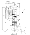
- FIG. 1 shows flue gas ducts 1 from a conventional furnace 3 (partially shown).
- the flue gas ducts 1 include a top pass 7 starting above a nose 5 of the furnace 3 connecting to a backpass 9.
- the backpass 9 extends downward to an economizer gas outlet duct 11.
- a backpass outlet manifold 12 attached to the economizer gas outlet duct 11.
- the backpass outlet manifold 12 includes an ash hopper 45 adapted to collect fly ash carried by the flue gases.
- Support structures 37 extend over the furnace and flue gas ducts 1.
- the furnace 3 and flue gas ducts 1 typically are hung from the support structures 37 with hanger rods 39.
- the furnace 3 is typically fixed at its top left.
- An air preheater duct 10 extends vertically from the air preheater (not shown) that is secured to a floor. When air preheater duct 10 heats up, it expands upward in the direction shown by arrow "C". An elbow duct 19 is attached to the air preheater duct 10, which also moves upward as air preheater duct 10 expands. The motion due to thermal expansion causes the backpass outlet manifold 12 to become misaligned with the elbow duct 19.
- toggle section 13 is typically employed to adjust for the misalignment and movement due to thermal expansion.
- the toggle section 13 is designed to make a gas tight connection between the backpass outlet manifold 12 and the elbow duct 19. Since the expansions cause motion in the three directions indicated by arrows "A", "B” and “C", there should be some flexibility built into the toggle section 13.
- Toggle section 13 includes expansion joints 15 on either side of a toggle duct 17. These are designed to adjust to the various movements of the ducts.
- toggle section 13 employed to become larger and heavier.
- These larger toggle sections 13 require additional support structures and make the system more expensive.
- Reheater vertical tubes 41 support the reheaters 29 and economizer vertical tubes 43 support the economizers 33 in the backpass 9.
- the fly ash and hopper 45 add considerable weight that must supported by the vertical tubes 41, 43, support structures 37 and hanger rods 39.
- An embodiment of the present invention may be described as a compensation duct assembly [100] adapted to convey combustion flue gases from a backpass outlet [111] at a lower end of a backpass wall [129] to an air preheater duct [10] while compensating for thermal expansion.
- the device includes a connection duct [110] that is a flue gas conduit with a top side [151], a bottom side [153], a backpass end [155], an air preheater end [157], a connection duct upper opening [115] on a top side [151] of its backpass end [155], sized and shaped substantially the same as the backpass outlet [111] with an air preheater opening [133] at its air preheater end [157] on its bottom side [153] connected to the air preheater duct [10].
- the compensation duct assembly [100] also employs a liquid seal [120] between the connection duct upper opening [115] of the connection duct [110] and the lower end of the backpass wall [129] acting to create a gas-tight seal between them.
- the present invention may also be described as a method for creating a gas tight seal during thermal expansion between a backpass [9] of a furnace [3] and a relatively fixed duct 10, comprising the steps of:
- connection duct [110] being a flue gas conduit having an air preheater end, a backpass end a top side and a bottom side;
- Figure 1 is a side elevational view of conventional steam generator with backpass
- Figure 2 is a side elevational view of a steam generator retrofitted with a flue gas connection according to one embodiment of the present invention.
- Figure 3 is an enlarged side elevational view of a portion of the water seal according to an embodiment of the present invention.
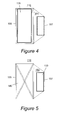
- Figure 4 is a plan view of the connection duct 110, from the top.
- Figure 5 is a plan view of the connection duct 110, from the bottom.
- Figure 6 is a plan view of the backpass, viewed from below.
- hot flue gases from the furnace 3 pass over super heaters 21 located in the top of the furnace and in a top pass 7. They receive steam and superheat the steam.
- the superheated steam is collected at the superheat headers 23.
- steam enters the reheaters 25 in the top pass 7.
- the backpass is lined with water tubes, but for clarity, are not shown here.
- the lower backpass 9 has economizers 33 that receive feedwater, heat the feedwater.
- the heated feedwater is collected at a backpass lower ring header 35 and provide the heated feedwater to waterwalls of the furnace 3.
- the top left of a furnace 3 is fixed to a stationary structure.
- the furnace 3 and flue gas ducts 1 expand to the right as indicated by arrow "B" and downward as indicated by arrow "C".
- An elbow duct 19 is connected to the air preheater duct 10 that is connected to the air preheater that is fixed to the ground. Therefore, it can only expand upward, as shown by arrow "C".
- the expansion, measured at the backpass lower ring header 35 can be typically 30.5 cm. (12 inches) down, 12.7 cm. (5 inches) rearward, and 6.4 cm. (21 ⁇ 2 inches) out to the sides.
- the toggle section 13 must be able to adjust for the relative movement between these ducts.
- Expansion joints 15 are on each side of toggle duct 17. These allow for the required adjustments.
- the toggle section 13, as well as the ash hopper (with ash), economizer gas outlet duct 11, backpass 9, top pass 7 and furnace 3 are all suspended from hangar rods 39 which hang down from the support structure 37.
- the toggle section 13 tends to leak once the expansion becomes larger.
- the present invention eliminates the backpass outlet manifold 12, the toggle section 13 and the elbow duct 19 by replacing them with a compensation duct assembly 100.
- the compensation duct assembly 100 is secured to the air preheater duct 10.
- Compensation duct assembly 100 employs a liquid seal 120 which allows for horizontal motions in two dimensions as well as vertical motion, while maintaining a gas-tight seal.
- Figure 3 shows an enlarged view of a portion of the liquid seal 120.
- the liquid seal 120 can compensate for the expansion differential in all three directions.
- the backpass wall 129 on one side is shown.
- the backpass wall 129 is immersed in a trough 121 filled with a liquid 131, preferably water.
- the trough 121 has an inner wall 123, and outer wall 127 and a bottom 125. (It is assumed that the trough continues around the periphery defined by the backpass wall 129.)
- the backpass wall 129 may move relative to the trough 121. However, if the trough is sufficiently long, wide and deep enough, there will be a gas-tight seal between the backpass 9 and the compensation duct assembly 100, even during expansion.
- Figure 4 is a plan view of the connection duct 110, from the top. Here the connection duct upper opening 115 is visible on the top side 151 at the backpass end 155. This is intended to connect, through the liquid seal, to the backpass (9 of Figure 1 ).
- Figure 5 is a plan view of the connection duct 110, from the bottom. This shows the bottom side 153 and the air preheater opening 133.
- Figure 6 is a plan view of a lower section of the backpass (9 of Figure 1 ), viewed from below. Here the backpass wall 129 and the back outlet 111 are visible.
- An advantage of using a liquid seal 120 is that all of the weight of the compensation duct assembly 100, including the ash loading in the ash hopper 145 goes directly into the local duct supporting steel, rather than being transferred into the backpass pressure parts of the reheater 29, the economizer 33, especially the backpass lower ring header (35) and the backpass wall tubes (not numbered) and up to the support structure 37, as it is done in the prior art design. This would require heavier and thicker pipes, adding cost.
- Another advantage of the present invention is that it would reduce the need for the toggle section 13 reducing the 'footprint' size, requiring less real estate resulting in a cost saving.
- Another advantage is that all movement compensation is performed in the liquid seal 120.
- the other connections are now standard connections. Therefore, there is less probability of leaks and other irregularities.
Landscapes
- Engineering & Computer Science (AREA)
- Mechanical Engineering (AREA)
- General Engineering & Computer Science (AREA)
- Chemical & Material Sciences (AREA)
- Combustion & Propulsion (AREA)
- Air Supply (AREA)
Abstract
Description
- The present disclosure generally relates to a furnace flue gas connection that adjusts to movement caused by expansion.
- Various furnaces are used in industry to create power, incinerate waste or perform chemical processes. The flue gases are conveyed by interconnected flue gas ducts. These must maintain a gas-tight seal to prevent leakage of flue gases.
-
Figure 1 showsflue gas ducts 1 from a conventional furnace 3 (partially shown). Theflue gas ducts 1 include a top pass 7 starting above anose 5 of thefurnace 3 connecting to abackpass 9. - The
backpass 9 extends downward to an economizergas outlet duct 11. Abackpass outlet manifold 12 attached to the economizergas outlet duct 11. Thebackpass outlet manifold 12 includes anash hopper 45 adapted to collect fly ash carried by the flue gases. -
Support structures 37 extend over the furnace andflue gas ducts 1. Thefurnace 3 andflue gas ducts 1 typically are hung from thesupport structures 37 withhanger rods 39. Thefurnace 3 is typically fixed at its top left. When thebackpass 9 and theflue gas ducts 1 expand, they move downward as shown by arrow "A" and to the right, as indicated by arrow "B". - An
air preheater duct 10 extends vertically from the air preheater (not shown) that is secured to a floor. Whenair preheater duct 10 heats up, it expands upward in the direction shown by arrow "C". Anelbow duct 19 is attached to theair preheater duct 10, which also moves upward asair preheater duct 10 expands. The motion due to thermal expansion causes thebackpass outlet manifold 12 to become misaligned with theelbow duct 19. - Therefore a
toggle section 13 is typically employed to adjust for the misalignment and movement due to thermal expansion. Thetoggle section 13 is designed to make a gas tight connection between thebackpass outlet manifold 12 and theelbow duct 19. Since the expansions cause motion in the three directions indicated by arrows "A", "B" and "C", there should be some flexibility built into thetoggle section 13. - Toggle
section 13 includesexpansion joints 15 on either side of atoggle duct 17. These are designed to adjust to the various movements of the ducts. - With the increase in size and power of furnaces and boilers, there is increased expansion requiring the
toggle section 13 employed to become larger and heavier. Theselarger toggle sections 13 require additional support structures and make the system more expensive. - Reheater
vertical tubes 41 support thereheaters 29 and economizervertical tubes 43 support theeconomizers 33 in thebackpass 9. - The fly ash and
hopper 45 add considerable weight that must supported by thevertical tubes support structures 37 andhanger rods 39. - Since the toggle sections are getting larger with larger boilers, they require extra room, which results in a larger `footprint'. This larger footprint also incurs increased costs.
- Currently, there need for a device to provide a lighter, smaller, simpler, and less expensive gas-tight connection to connect misaligned flue gas ducts.
- An embodiment of the present invention may be described as a compensation duct assembly [100] adapted to convey combustion flue gases from a backpass outlet [111] at a lower end of a backpass wall [129] to an air preheater duct [10] while compensating for thermal expansion. The device includes a connection duct [110] that is a flue gas conduit with a top side [151], a bottom side [153], a backpass end [155], an air preheater end [157], a connection duct upper opening [115] on a top side [151] of its backpass end [155], sized and shaped substantially the same as the backpass outlet [111] with an air preheater opening [133] at its air preheater end [157] on its bottom side [153] connected to the air preheater duct [10]. The compensation duct assembly [100] also employs a liquid seal [120] between the connection duct upper opening [115] of the connection duct [110] and the lower end of the backpass wall [129] acting to create a gas-tight seal between them.
- The present invention may also be described as a method for creating a gas tight seal during thermal expansion between a backpass [9] of a furnace [3] and a relatively fixed
duct 10, comprising the steps of: - providing a connection duct [110] being a flue gas conduit having an air preheater end, a backpass end a top side and a bottom side;
- attaching the air preheater end of the connection duct [110] to said air preheater duct [10];
- providing a liquid seal [120] at the topside of the backpass end of a connection duct [110]; and
- inserting a lower portion of the backpass [9] into the liquid seal [120] to result in a gas seal that compensates for movement due to thermal expansion.
- The disclosure may be understood more readily by reference to the following detailed description of the various features of the disclosure and the examples included therein.
- Referring now to the figures wherein the like elements are numbered alike:
-
Figure 1 is a side elevational view of conventional steam generator with backpass; -
Figure 2 is a side elevational view of a steam generator retrofitted with a flue gas connection according to one embodiment of the present invention. -
Figure 3 is an enlarged side elevational view of a portion of the water seal according to an embodiment of the present invention. -
Figure 4 is a plan view of theconnection duct 110, from the top. -
Figure 5 is a plan view of theconnection duct 110, from the bottom. -
Figure 6 is a plan view of the backpass, viewed from below. - Referring now to
Figure 1 , hot flue gases from thefurnace 3 pass oversuper heaters 21 located in the top of the furnace and in a top pass 7. They receive steam and superheat the steam. The superheated steam is collected at thesuperheat headers 23. Similarly, steam enters thereheaters 25 in the top pass 7. There are alsoreheaters 29 andreheater headers 31 in abackpass 9. The backpass is lined with water tubes, but for clarity, are not shown here. - The
lower backpass 9 haseconomizers 33 that receive feedwater, heat the feedwater. The heated feedwater is collected at a backpasslower ring header 35 and provide the heated feedwater to waterwalls of thefurnace 3. - Typically, the top left of a
furnace 3 is fixed to a stationary structure. When operating, thefurnace 3 andflue gas ducts 1 expand to the right as indicated by arrow "B" and downward as indicated by arrow "C". - An
elbow duct 19 is connected to theair preheater duct 10 that is connected to the air preheater that is fixed to the ground. Therefore, it can only expand upward, as shown by arrow "C". - The expansion, measured at the backpass
lower ring header 35 can be typically 30.5 cm. (12 inches) down, 12.7 cm. (5 inches) rearward, and 6.4 cm. (2½ inches) out to the sides. - The
toggle section 13 must be able to adjust for the relative movement between these ducts.Expansion joints 15 are on each side oftoggle duct 17. These allow for the required adjustments. - The
toggle section 13, as well as the ash hopper (with ash), economizergas outlet duct 11,backpass 9, top pass 7 andfurnace 3 are all suspended fromhangar rods 39 which hang down from thesupport structure 37. - Therefore, the cost of the
support structure 37 increases with the amount of weight it must support. - It would be useful to compensate for flue gas duct expansion at the interface with the
air preheater duct 10 which does not necessitate the use of atoggle section 13. - The
toggle section 13 tends to leak once the expansion becomes larger. - Referring now to both
Figures 1 and2 , the present invention eliminates thebackpass outlet manifold 12, thetoggle section 13 and theelbow duct 19 by replacing them with acompensation duct assembly 100. Thecompensation duct assembly 100 is secured to theair preheater duct 10. - There is no longer a
toggle section 13, so thecompensation duct assembly 100 does not float as did thebackpass outlet manifold 12. Now all of the expansion motions are centralized at the interface of the bottom of thebackpass 9 and thecompensation duct assembly 100. -
Compensation duct assembly 100 employs aliquid seal 120 which allows for horizontal motions in two dimensions as well as vertical motion, while maintaining a gas-tight seal. -
Figure 3 shows an enlarged view of a portion of theliquid seal 120. - The
liquid seal 100 located below the backpasslower ring header 35. Theliquid seal 120 can compensate for the expansion differential in all three directions. Here thebackpass wall 129 on one side is shown. Thebackpass wall 129 is immersed in atrough 121 filled with a liquid 131, preferably water. Thetrough 121 has aninner wall 123, andouter wall 127 and a bottom 125. (It is assumed that the trough continues around the periphery defined by thebackpass wall 129.) As shown by the arrows, thebackpass wall 129 may move relative to thetrough 121. However, if the trough is sufficiently long, wide and deep enough, there will be a gas-tight seal between thebackpass 9 and thecompensation duct assembly 100, even during expansion. -
Figure 4 is a plan view of theconnection duct 110, from the top. Here the connection ductupper opening 115 is visible on thetop side 151 at thebackpass end 155. This is intended to connect, through the liquid seal, to the backpass (9 ofFigure 1 ). -
Figure 5 is a plan view of theconnection duct 110, from the bottom. This shows thebottom side 153 and theair preheater opening 133. -
Figure 6 is a plan view of a lower section of the backpass (9 ofFigure 1 ), viewed from below. Here thebackpass wall 129 and theback outlet 111 are visible. - An advantage of using a
liquid seal 120 is that all of the weight of thecompensation duct assembly 100, including the ash loading in theash hopper 145 goes directly into the local duct supporting steel, rather than being transferred into the backpass pressure parts of thereheater 29, theeconomizer 33, especially the backpass lower ring header (35) and the backpass wall tubes (not numbered) and up to thesupport structure 37, as it is done in the prior art design. This would require heavier and thicker pipes, adding cost. - Another advantage of the present invention is that it would reduce the need for the
toggle section 13 reducing the 'footprint' size, requiring less real estate resulting in a cost saving. - Another advantage is that all movement compensation is performed in the
liquid seal 120. The other connections are now standard connections. Therefore, there is less probability of leaks and other irregularities. - Unless otherwise specified, all ranges disclosed herein are inclusive and combinable at the end points and all intermediate points therein. The terms "first," "second," and the like, herein do not denote any order, quantity, or importance, but rather are used to distinguish one element from another. The terms "a" and "an" herein do not denote a limitation of quantity, but rather denote the presence of at least one of the referenced item. All numerals modified by "about" are inclusive of the precise numeric value unless otherwise specified.
- This written description uses examples to disclose the invention, including the best mode, and also to enable any person skilled in the art to make and use the invention. The patentable scope of the invention is defined by the claims, and may include other examples that occur to those skilled in the art. Such other examples are intended to be within the scope of the claims if they have structural elements that do not differ from the literal language of the claims, or if they include equivalent structural elements with insubstantial differences from the literal languages of the claims.
Claims (12)
- A compensation duct assembly adapted to convey combustion flue gases from a backpass outlet at a lower end of a backpass having a backpass wall, to an air preheater duct while compensating for thermal expansion, comprising:a connection duct being a flue gas conduit having:a top side,a bottom side,a backpass end,an air preheater end,a connection duct upper opening on the top side of its backpass end, sized and shaped substantially the same as the backpass outlet;an air preheater opening at its air preheater end on its bottom side connected to the air preheater duct; anda liquid seal between the connection duct upper opening of the connection duct and the lower end of the backpass wall acting to create a gas-tight seal between them.
- The compensation duct assembly of claim 1, wherein the liquid seal further comprises:a trough filled with a liquid;wherein the backpass wall is at least partially inserted into the liquid in the trough thereby creating a gas-tight seal between the backpass [9] and the liquid seal
- The compensation duct assembly of claim 1 further comprising:a floor support being a support fixed with respect to a floor, the floor support supporting the compensation duct assembly.
- The compensation duct assembly of claim 2 wherein:the trough is sized to compensate for movement due to thermal expansion in a forward-backward direction.
- The compensation duct assembly of claim 2 wherein:the trough is sized to compensate for movement due to thermal expansion in a horizontal direction.
- The compensation duct assembly of claim 2 wherein:the trough is sized to compensate for movement due to thermal expansion in a vertical direction.
- The compensation duct assembly of claim 1 wherein the compensation duct assembly is sized and shaped to retrofit existing prior art toggle sections.
- The compensation duct assembly of claim 3 further comprising:an ash hopper on its bottom side supported by the floor support.
- The compensation duct assembly of claim 3 wherein the backpass is supported from above by at least one hanger rod connected to a support structure.
- The compensation duct assembly of claim 2 wherein the liquid comprises water.
- A method of creating a gas tight seal during thermal expansion between a backpass of a furnace and an air preheater duct, comprising:providing a connection duct being a flue gas conduit having a top side a bottom side a backpass end and an air preheater end;attaching the air preheater end of the connection duct to said air preheater duct;providing a liquid seal at the topside of the backpass end of a connection duct;inserting a lower portion of the backpass into the liquid seal to result in a gas seal that compensates for movement due to thermal expansion.
- The method of claim 11 wherein the step of attaching a providing a liquid seal [120] comprises the steps of:providing a connection duct having connection duct upper opening in a top side [151] of the connection duct at its backpass end;providing a trough shaped and size to receive a lower wall of the backpass, the trough being partially filled with a liquid,inserting a lower end of a backpass wall into the trough of the liquid seal of the connection duct to result in a gas seal that compensates for thermal expansion.
Applications Claiming Priority (1)
| Application Number | Priority Date | Filing Date | Title |
|---|---|---|---|
| US13/461,019 US9322550B2 (en) | 2012-05-01 | 2012-05-01 | Water seal at backpass economizer gas outlet |
Publications (3)
| Publication Number | Publication Date |
|---|---|
| EP2660517A2 true EP2660517A2 (en) | 2013-11-06 |
| EP2660517A3 EP2660517A3 (en) | 2017-12-20 |
| EP2660517B1 EP2660517B1 (en) | 2020-01-15 |
Family
ID=48288836
Family Applications (1)
| Application Number | Title | Priority Date | Filing Date |
|---|---|---|---|
| EP13166088.8A Active EP2660517B1 (en) | 2012-05-01 | 2013-04-30 | Water seal at backpass economizer gas outlet |
Country Status (3)
| Country | Link |
|---|---|
| US (1) | US9322550B2 (en) |
| EP (1) | EP2660517B1 (en) |
| CN (1) | CN103383110A (en) |
Families Citing this family (2)
| Publication number | Priority date | Publication date | Assignee | Title |
|---|---|---|---|---|
| CN109058527A (en) * | 2018-09-26 | 2018-12-21 | 洛阳明远石化技术有限公司 | Water-sealed valve and the chimney for being built-in with the water-sealed valve |
| CN114210145B (en) * | 2021-12-17 | 2022-09-13 | 南京工业大学 | Ash discharging sealing system at bottom of high-temperature ceramic film dust collector |
Family Cites Families (25)
| Publication number | Priority date | Publication date | Assignee | Title |
|---|---|---|---|---|
| US3580226A (en) * | 1969-12-04 | 1971-05-25 | Combustion Eng | Steam generator using gas recirculation |
| US3605776A (en) * | 1970-04-29 | 1971-09-20 | Allied Chem | Gas vent relief device |
| US3834328A (en) * | 1973-07-11 | 1974-09-10 | Babcock & Wilcox Co | Furnace seal |
| US3860224A (en) * | 1973-10-19 | 1975-01-14 | Eveleth Taconite Company | Apparatus for use in pelletizing ore |
| JPS576225A (en) | 1980-06-12 | 1982-01-13 | Toa Seiki Kk | Structure of high chimney |
| JPS5795503A (en) | 1980-12-04 | 1982-06-14 | Mitsubishi Heavy Ind Ltd | Seal bellows apparatus |
| US4359949A (en) * | 1981-10-15 | 1982-11-23 | Combustion Engineering, Inc. | Structural water seal trough |
| JPS58156776A (en) | 1982-03-10 | 1983-09-17 | Babcock Hitachi Kk | Sealing device for duct |
| US4510892A (en) | 1984-06-18 | 1985-04-16 | Combustion Engineering, Inc. | Seal for boiler water wall |
| JPS6183822A (en) | 1984-09-28 | 1986-04-28 | Fuji Kako Kk | Expansion joint of cylindrical body in smokestack inner cylinder |
| US4610697A (en) * | 1984-12-19 | 1986-09-09 | Combustion Engineering, Inc. | Coal gasification system with product gas recycle to pressure containment chamber |
| US4648353A (en) * | 1985-05-31 | 1987-03-10 | The Babcock & Wilcox Company | Fluidized sand expansion joint |
| JPH01217117A (en) | 1988-02-26 | 1989-08-30 | Babcock Hitachi Kk | Duct device |
| JP2659849B2 (en) * | 1990-05-30 | 1997-09-30 | 三菱重工業株式会社 | Pressurized gasifier |
| US5435257A (en) * | 1993-12-17 | 1995-07-25 | Combustion Engineering, Inc. | Apparatus for introducing gas recirculation into a furnace |
| US5678494A (en) * | 1995-03-22 | 1997-10-21 | Ulrich; Gael | Biomass-fueled furnace |
| US5980610A (en) * | 1997-09-25 | 1999-11-09 | The United States Of America As Represented By The United States Department Of Energy | Apparatus and method for improving electrostatic precipitator performance by plasma reactor conversion of SO2 to SO3 |
| US5967098A (en) * | 1998-06-22 | 1999-10-19 | Tanca; Michael C. | Oil shale fluidized bed |
| US5988115A (en) * | 1998-08-11 | 1999-11-23 | Anderson; David K. | SCR reactant injection grid |
| US5943865A (en) * | 1998-12-03 | 1999-08-31 | Cohen; Mitchell B. | Reheating flue gas for selective catalytic systems |
| US6305330B1 (en) * | 2000-03-03 | 2001-10-23 | Foster Wheeler Corporation | Circulating fluidized bed combustion system including a heat exchange chamber between a separating section and a furnace section |
| JP3745973B2 (en) * | 2001-03-23 | 2006-02-15 | タイホー工業株式会社 | Coal additive for preventing slagging and coal combustion method |
| NO316953B1 (en) * | 2002-02-18 | 2004-07-05 | Aibel Gas Technology As | Method and apparatus for handling hydrocarbon gas, as well as its use |
| FI20065308A7 (en) * | 2006-05-10 | 2007-11-11 | Foster Wheeler Energia Oy | Fluidized bed heat exchanger of a circulating bed boiler and a circulating bed boiler with a fluidized bed heat exchanger |
| CN201526948U (en) | 2009-09-30 | 2010-07-14 | 哈尔滨锅炉厂有限责任公司 | 350MW supercritical coal-fired boiler with variable pressure operation |
-
2012
- 2012-05-01 US US13/461,019 patent/US9322550B2/en not_active Expired - Fee Related
-
2013
- 2013-04-30 EP EP13166088.8A patent/EP2660517B1/en active Active
- 2013-05-02 CN CN2013101864425A patent/CN103383110A/en active Pending
Non-Patent Citations (1)
| Title |
|---|
| None |
Also Published As
| Publication number | Publication date |
|---|---|
| US20130291856A1 (en) | 2013-11-07 |
| EP2660517A3 (en) | 2017-12-20 |
| CN103383110A (en) | 2013-11-06 |
| EP2660517B1 (en) | 2020-01-15 |
| US9322550B2 (en) | 2016-04-26 |
Similar Documents
| Publication | Publication Date | Title |
|---|---|---|
| CN203258632U (en) | Supercritical brown coal boiler | |
| EP2447587B1 (en) | Piping system | |
| FI129828B (en) | Support assembly for a steam boiler | |
| EP2660517B1 (en) | Water seal at backpass economizer gas outlet | |
| CN201443755U (en) | Labyrinth type expansion joint of slag discharge pipe of circulating fluidized bed boiler | |
| EP1867909A2 (en) | Pipe penetration system | |
| CN112460338B (en) | Sealing structure for tower type boiler wall penetrating pipe | |
| JP6122744B2 (en) | Seismic tie for boiler vibration control and boiler seismic structure using the same | |
| CN205424099U (en) | Novel gallows system in air heater of thermal power factory export wind channel of heat | |
| CN216769042U (en) | Overhead steam pipeline suspension type drainage system | |
| CN205102103U (en) | Be applied to over heater of boiler | |
| CN115596408A (en) | Large-displacement steam pipe line device of ocean mobile heat injection system and heat injection method | |
| CN106195980A (en) | A kind of pendant superheater and the multipath circulating fluidized bed boiler of application thereof | |
| JP4410433B2 (en) | Boiler support structure | |
| CN222503832U (en) | A circulating fluidized bed boiler | |
| CN106090515A (en) | A kind of low-voltage high-temperature restricted type expansion joint floating installation | |
| JP2009097739A (en) | Supporting structure of header | |
| FI129922B (en) | Support assembly for a steam boiler | |
| CN209263763U (en) | A kind of set of heat exchange tubes mounting structure for waste heat boiler | |
| CN105222122A (en) | Be applied to the superheater of boiler | |
| CN110892195A (en) | System and method for connecting pipe segments of a solids return system of a boiler | |
| KR20180042150A (en) | Circulating fluidized bed apparatus | |
| CN103168199A (en) | Wall construction for a boiler arrangement | |
| EP3130849A1 (en) | Circulating fluidized bed furnace | |
| PL228130B1 (en) | Multidirectional cmpensator |
Legal Events
| Date | Code | Title | Description |
|---|---|---|---|
| PUAI | Public reference made under article 153(3) epc to a published international application that has entered the european phase |
Free format text: ORIGINAL CODE: 0009012 |
|
| AK | Designated contracting states |
Kind code of ref document: A2 Designated state(s): AL AT BE BG CH CY CZ DE DK EE ES FI FR GB GR HR HU IE IS IT LI LT LU LV MC MK MT NL NO PL PT RO RS SE SI SK SM TR |
|
| AX | Request for extension of the european patent |
Extension state: BA ME |
|
| RAP1 | Party data changed (applicant data changed or rights of an application transferred) |
Owner name: GENERAL ELECTRIC TECHNOLOGY GMBH |
|
| PUAL | Search report despatched |
Free format text: ORIGINAL CODE: 0009013 |
|
| AK | Designated contracting states |
Kind code of ref document: A3 Designated state(s): AL AT BE BG CH CY CZ DE DK EE ES FI FR GB GR HR HU IE IS IT LI LT LU LV MC MK MT NL NO PL PT RO RS SE SI SK SM TR |
|
| AX | Request for extension of the european patent |
Extension state: BA ME |
|
| RIC1 | Information provided on ipc code assigned before grant |
Ipc: F23J 11/00 20060101ALI20171115BHEP Ipc: F23L 15/04 20060101AFI20171115BHEP |
|
| STAA | Information on the status of an ep patent application or granted ep patent |
Free format text: STATUS: REQUEST FOR EXAMINATION WAS MADE |
|
| 17P | Request for examination filed |
Effective date: 20180620 |
|
| RBV | Designated contracting states (corrected) |
Designated state(s): AL AT BE BG CH CY CZ DE DK EE ES FI FR GB GR HR HU IE IS IT LI LT LU LV MC MK MT NL NO PL PT RO RS SE SI SK SM TR |
|
| GRAP | Despatch of communication of intention to grant a patent |
Free format text: ORIGINAL CODE: EPIDOSNIGR1 |
|
| STAA | Information on the status of an ep patent application or granted ep patent |
Free format text: STATUS: GRANT OF PATENT IS INTENDED |
|
| INTG | Intention to grant announced |
Effective date: 20190621 |
|
| GRAS | Grant fee paid |
Free format text: ORIGINAL CODE: EPIDOSNIGR3 |
|
| GRAJ | Information related to disapproval of communication of intention to grant by the applicant or resumption of examination proceedings by the epo deleted |
Free format text: ORIGINAL CODE: EPIDOSDIGR1 |
|
| GRAL | Information related to payment of fee for publishing/printing deleted |
Free format text: ORIGINAL CODE: EPIDOSDIGR3 |
|
| STAA | Information on the status of an ep patent application or granted ep patent |
Free format text: STATUS: REQUEST FOR EXAMINATION WAS MADE |
|
| GRAR | Information related to intention to grant a patent recorded |
Free format text: ORIGINAL CODE: EPIDOSNIGR71 |
|
| STAA | Information on the status of an ep patent application or granted ep patent |
Free format text: STATUS: GRANT OF PATENT IS INTENDED |
|
| INTC | Intention to grant announced (deleted) | ||
| GRAA | (expected) grant |
Free format text: ORIGINAL CODE: 0009210 |
|
| STAA | Information on the status of an ep patent application or granted ep patent |
Free format text: STATUS: THE PATENT HAS BEEN GRANTED |
|
| INTG | Intention to grant announced |
Effective date: 20191205 |
|
| AK | Designated contracting states |
Kind code of ref document: B1 Designated state(s): AL AT BE BG CH CY CZ DE DK EE ES FI FR GB GR HR HU IE IS IT LI LT LU LV MC MK MT NL NO PL PT RO RS SE SI SK SM TR |
|
| REG | Reference to a national code |
Ref country code: CH Ref legal event code: EP Ref country code: GB Ref legal event code: FG4D |
|
| REG | Reference to a national code |
Ref country code: IE Ref legal event code: FG4D |
|
| REG | Reference to a national code |
Ref country code: DE Ref legal event code: R096 Ref document number: 602013065052 Country of ref document: DE |
|
| REG | Reference to a national code |
Ref country code: AT Ref legal event code: REF Ref document number: 1225473 Country of ref document: AT Kind code of ref document: T Effective date: 20200215 |
|
| REG | Reference to a national code |
Ref country code: NL Ref legal event code: MP Effective date: 20200115 |
|
| REG | Reference to a national code |
Ref country code: LT Ref legal event code: MG4D |
|
| PG25 | Lapsed in a contracting state [announced via postgrant information from national office to epo] |
Ref country code: NO Free format text: LAPSE BECAUSE OF FAILURE TO SUBMIT A TRANSLATION OF THE DESCRIPTION OR TO PAY THE FEE WITHIN THE PRESCRIBED TIME-LIMIT Effective date: 20200415 Ref country code: PT Free format text: LAPSE BECAUSE OF FAILURE TO SUBMIT A TRANSLATION OF THE DESCRIPTION OR TO PAY THE FEE WITHIN THE PRESCRIBED TIME-LIMIT Effective date: 20200607 Ref country code: NL Free format text: LAPSE BECAUSE OF FAILURE TO SUBMIT A TRANSLATION OF THE DESCRIPTION OR TO PAY THE FEE WITHIN THE PRESCRIBED TIME-LIMIT Effective date: 20200115 Ref country code: FI Free format text: LAPSE BECAUSE OF FAILURE TO SUBMIT A TRANSLATION OF THE DESCRIPTION OR TO PAY THE FEE WITHIN THE PRESCRIBED TIME-LIMIT Effective date: 20200115 Ref country code: RS Free format text: LAPSE BECAUSE OF FAILURE TO SUBMIT A TRANSLATION OF THE DESCRIPTION OR TO PAY THE FEE WITHIN THE PRESCRIBED TIME-LIMIT Effective date: 20200115 |
|
| PGFP | Annual fee paid to national office [announced via postgrant information from national office to epo] |
Ref country code: DE Payment date: 20200319 Year of fee payment: 8 |
|
| PG25 | Lapsed in a contracting state [announced via postgrant information from national office to epo] |
Ref country code: BG Free format text: LAPSE BECAUSE OF FAILURE TO SUBMIT A TRANSLATION OF THE DESCRIPTION OR TO PAY THE FEE WITHIN THE PRESCRIBED TIME-LIMIT Effective date: 20200415 Ref country code: IS Free format text: LAPSE BECAUSE OF FAILURE TO SUBMIT A TRANSLATION OF THE DESCRIPTION OR TO PAY THE FEE WITHIN THE PRESCRIBED TIME-LIMIT Effective date: 20200515 Ref country code: GR Free format text: LAPSE BECAUSE OF FAILURE TO SUBMIT A TRANSLATION OF THE DESCRIPTION OR TO PAY THE FEE WITHIN THE PRESCRIBED TIME-LIMIT Effective date: 20200416 Ref country code: HR Free format text: LAPSE BECAUSE OF FAILURE TO SUBMIT A TRANSLATION OF THE DESCRIPTION OR TO PAY THE FEE WITHIN THE PRESCRIBED TIME-LIMIT Effective date: 20200115 Ref country code: SE Free format text: LAPSE BECAUSE OF FAILURE TO SUBMIT A TRANSLATION OF THE DESCRIPTION OR TO PAY THE FEE WITHIN THE PRESCRIBED TIME-LIMIT Effective date: 20200115 Ref country code: LV Free format text: LAPSE BECAUSE OF FAILURE TO SUBMIT A TRANSLATION OF THE DESCRIPTION OR TO PAY THE FEE WITHIN THE PRESCRIBED TIME-LIMIT Effective date: 20200115 |
|
| REG | Reference to a national code |
Ref country code: DE Ref legal event code: R097 Ref document number: 602013065052 Country of ref document: DE |
|
| PG25 | Lapsed in a contracting state [announced via postgrant information from national office to epo] |
Ref country code: ES Free format text: LAPSE BECAUSE OF FAILURE TO SUBMIT A TRANSLATION OF THE DESCRIPTION OR TO PAY THE FEE WITHIN THE PRESCRIBED TIME-LIMIT Effective date: 20200115 Ref country code: DK Free format text: LAPSE BECAUSE OF FAILURE TO SUBMIT A TRANSLATION OF THE DESCRIPTION OR TO PAY THE FEE WITHIN THE PRESCRIBED TIME-LIMIT Effective date: 20200115 Ref country code: CZ Free format text: LAPSE BECAUSE OF FAILURE TO SUBMIT A TRANSLATION OF THE DESCRIPTION OR TO PAY THE FEE WITHIN THE PRESCRIBED TIME-LIMIT Effective date: 20200115 Ref country code: EE Free format text: LAPSE BECAUSE OF FAILURE TO SUBMIT A TRANSLATION OF THE DESCRIPTION OR TO PAY THE FEE WITHIN THE PRESCRIBED TIME-LIMIT Effective date: 20200115 Ref country code: RO Free format text: LAPSE BECAUSE OF FAILURE TO SUBMIT A TRANSLATION OF THE DESCRIPTION OR TO PAY THE FEE WITHIN THE PRESCRIBED TIME-LIMIT Effective date: 20200115 Ref country code: SM Free format text: LAPSE BECAUSE OF FAILURE TO SUBMIT A TRANSLATION OF THE DESCRIPTION OR TO PAY THE FEE WITHIN THE PRESCRIBED TIME-LIMIT Effective date: 20200115 Ref country code: LT Free format text: LAPSE BECAUSE OF FAILURE TO SUBMIT A TRANSLATION OF THE DESCRIPTION OR TO PAY THE FEE WITHIN THE PRESCRIBED TIME-LIMIT Effective date: 20200115 Ref country code: SK Free format text: LAPSE BECAUSE OF FAILURE TO SUBMIT A TRANSLATION OF THE DESCRIPTION OR TO PAY THE FEE WITHIN THE PRESCRIBED TIME-LIMIT Effective date: 20200115 |
|
| REG | Reference to a national code |
Ref country code: AT Ref legal event code: MK05 Ref document number: 1225473 Country of ref document: AT Kind code of ref document: T Effective date: 20200115 |
|
| PLBE | No opposition filed within time limit |
Free format text: ORIGINAL CODE: 0009261 |
|
| STAA | Information on the status of an ep patent application or granted ep patent |
Free format text: STATUS: NO OPPOSITION FILED WITHIN TIME LIMIT |
|
| PG25 | Lapsed in a contracting state [announced via postgrant information from national office to epo] |
Ref country code: MC Free format text: LAPSE BECAUSE OF FAILURE TO SUBMIT A TRANSLATION OF THE DESCRIPTION OR TO PAY THE FEE WITHIN THE PRESCRIBED TIME-LIMIT Effective date: 20200115 |
|
| REG | Reference to a national code |
Ref country code: CH Ref legal event code: PL |
|
| 26N | No opposition filed |
Effective date: 20201016 |
|
| PG25 | Lapsed in a contracting state [announced via postgrant information from national office to epo] |
Ref country code: IT Free format text: LAPSE BECAUSE OF FAILURE TO SUBMIT A TRANSLATION OF THE DESCRIPTION OR TO PAY THE FEE WITHIN THE PRESCRIBED TIME-LIMIT Effective date: 20200115 Ref country code: AT Free format text: LAPSE BECAUSE OF FAILURE TO SUBMIT A TRANSLATION OF THE DESCRIPTION OR TO PAY THE FEE WITHIN THE PRESCRIBED TIME-LIMIT Effective date: 20200115 Ref country code: LU Free format text: LAPSE BECAUSE OF NON-PAYMENT OF DUE FEES Effective date: 20200430 Ref country code: FR Free format text: LAPSE BECAUSE OF NON-PAYMENT OF DUE FEES Effective date: 20200430 Ref country code: LI Free format text: LAPSE BECAUSE OF NON-PAYMENT OF DUE FEES Effective date: 20200430 Ref country code: CH Free format text: LAPSE BECAUSE OF NON-PAYMENT OF DUE FEES Effective date: 20200430 |
|
| REG | Reference to a national code |
Ref country code: BE Ref legal event code: MM Effective date: 20200430 |
|
| PG25 | Lapsed in a contracting state [announced via postgrant information from national office to epo] |
Ref country code: PL Free format text: LAPSE BECAUSE OF FAILURE TO SUBMIT A TRANSLATION OF THE DESCRIPTION OR TO PAY THE FEE WITHIN THE PRESCRIBED TIME-LIMIT Effective date: 20200115 Ref country code: BE Free format text: LAPSE BECAUSE OF NON-PAYMENT OF DUE FEES Effective date: 20200430 Ref country code: SI Free format text: LAPSE BECAUSE OF FAILURE TO SUBMIT A TRANSLATION OF THE DESCRIPTION OR TO PAY THE FEE WITHIN THE PRESCRIBED TIME-LIMIT Effective date: 20200115 |
|
| GBPC | Gb: european patent ceased through non-payment of renewal fee |
Effective date: 20200430 |
|
| PG25 | Lapsed in a contracting state [announced via postgrant information from national office to epo] |
Ref country code: GB Free format text: LAPSE BECAUSE OF NON-PAYMENT OF DUE FEES Effective date: 20200430 Ref country code: IE Free format text: LAPSE BECAUSE OF NON-PAYMENT OF DUE FEES Effective date: 20200430 |
|
| REG | Reference to a national code |
Ref country code: DE Ref legal event code: R119 Ref document number: 602013065052 Country of ref document: DE |
|
| PG25 | Lapsed in a contracting state [announced via postgrant information from national office to epo] |
Ref country code: DE Free format text: LAPSE BECAUSE OF NON-PAYMENT OF DUE FEES Effective date: 20211103 |
|
| PG25 | Lapsed in a contracting state [announced via postgrant information from national office to epo] |
Ref country code: TR Free format text: LAPSE BECAUSE OF FAILURE TO SUBMIT A TRANSLATION OF THE DESCRIPTION OR TO PAY THE FEE WITHIN THE PRESCRIBED TIME-LIMIT Effective date: 20200115 Ref country code: MT Free format text: LAPSE BECAUSE OF FAILURE TO SUBMIT A TRANSLATION OF THE DESCRIPTION OR TO PAY THE FEE WITHIN THE PRESCRIBED TIME-LIMIT Effective date: 20200115 Ref country code: CY Free format text: LAPSE BECAUSE OF FAILURE TO SUBMIT A TRANSLATION OF THE DESCRIPTION OR TO PAY THE FEE WITHIN THE PRESCRIBED TIME-LIMIT Effective date: 20200115 |
|
| PG25 | Lapsed in a contracting state [announced via postgrant information from national office to epo] |
Ref country code: MK Free format text: LAPSE BECAUSE OF FAILURE TO SUBMIT A TRANSLATION OF THE DESCRIPTION OR TO PAY THE FEE WITHIN THE PRESCRIBED TIME-LIMIT Effective date: 20200115 Ref country code: AL Free format text: LAPSE BECAUSE OF FAILURE TO SUBMIT A TRANSLATION OF THE DESCRIPTION OR TO PAY THE FEE WITHIN THE PRESCRIBED TIME-LIMIT Effective date: 20200115 |
|
| P01 | Opt-out of the competence of the unified patent court (upc) registered |
Effective date: 20230523 |