EP2660470B1 - Removable connector for peristaltic pump - Google Patents
Removable connector for peristaltic pump Download PDFInfo
- Publication number
- EP2660470B1 EP2660470B1 EP20130002221 EP13002221A EP2660470B1 EP 2660470 B1 EP2660470 B1 EP 2660470B1 EP 20130002221 EP20130002221 EP 20130002221 EP 13002221 A EP13002221 A EP 13002221A EP 2660470 B1 EP2660470 B1 EP 2660470B1
- Authority
- EP
- European Patent Office
- Prior art keywords
- seat
- removable connector
- connector
- peristaltic pump
- housed
- Prior art date
- Legal status (The legal status is an assumption and is not a legal conclusion. Google has not performed a legal analysis and makes no representation as to the accuracy of the status listed.)
- Active
Links
Images


Classifications
-
- F—MECHANICAL ENGINEERING; LIGHTING; HEATING; WEAPONS; BLASTING
- F04—POSITIVE - DISPLACEMENT MACHINES FOR LIQUIDS; PUMPS FOR LIQUIDS OR ELASTIC FLUIDS
- F04B—POSITIVE-DISPLACEMENT MACHINES FOR LIQUIDS; PUMPS
- F04B43/00—Machines, pumps, or pumping installations having flexible working members
- F04B43/12—Machines, pumps, or pumping installations having flexible working members having peristaltic action
- F04B43/1253—Machines, pumps, or pumping installations having flexible working members having peristaltic action by using two or more rollers as squeezing elements, the rollers moving on an arc of a circle during squeezing
Definitions
- the present invention relates to a peristaltic pump comprising a removable connector.
- EP 1763636 B1 is considered to represent the closest prior art and discloses a roller or peristaltic pump comprising a stator provided with a pump seat formed therein, formed in the carter of the same, and a rotor, which acts on a flexible pipe disposed in an arcuate manner in said pump seat, and that is itself fixed to said peristaltic pump by means of a removable connector.
- Said removable connector realises the hydraulic connection between said flexible pipe inside said pump seat, and two flexible pipes, external to said pump seat, for the feed and delivery of a fluid. It is made of elastically flexible plastic material.
- the stator carter provides, laterally with respect to the pump seat, two fixing elements with different shapes, in order to permit the housing of said removable connector, which is fixed between the same to allow the shape mating and further elastic snap.
- one of said two fixing housings is made in the shape of a curvilinear arc, while the other of said two housings is made with angular configuration.
- said known removable connector has a structure which necessarily needs two following steps of implementation, that are:
- said known removable connector presents inevitable practical difficulties for the operator, both during the step of inserting between said two fixing housings, and the step of decomposition with respect to the same, since it does not permit an only and continuous operation of both insertion and fixing, in a fast way and in safety conditions.
- the present invention starting from the notion of the aforesaid problems, intends to provide a solution.
- An object of the present invention is to provide a removable connector for peristaltic pump, able to allow an easy and fast assembly and following decomposition, in fully safe conditions.
- a further object of the present invention is to provide a removable connector for peristaltic pump, having a simplified structure and relatively low costs.
- the present invention provides a removable connector for peristaltic pump, the essential characteristic of which forms the subject of claim 1.
- letter P indicates as a whole a peristaltic pump comprising a stator, having a pump seat S formed in the same, and a rotor R, which acts on a flexible pipe F, housed in an arcuate manner inside said pump seat S, and that is in turn fixed in said seat S by means of a removable connector 10, subject of the present invention.
- Said removable connector 10 realizes the hydraulic connection between said flexible pipe F inside said seat S, and two flexible pipes T, T' external to said seat S, for the feed and delivery of a fluid, in particular human blood.
- Said internal pipe F has a larger diameter than the one of said flexible pipes T, T'.
- Said removable connector 10 is made of elastically flexible plastic material.
- the stator carter of said peristaltic pump P has, in said seat S, a lateral opening A, delimited by two different-shaped fixing housings M, M', to permit the housing of said removable connector 10.
- said housing M is made with profile of a curvilinear arc, while the housing M' is made with angular configuration.
- said removable connector 10 comprises two tubular sections 11, 11', mutually superimposed and in a single body (refer to Figures 5 and 6 ).
- each of said tubular sections 11, 11' comprises:
- Each pair of ends of said tubular sections 11, 11' formed by a first and by a second of said ends 12/14', 12'/14 of the one and of the other tubular section 11, 11', provides, respectively, a substantially V-shaped elastic clamp 16, 16', which - when said connector 10 is housed in said opening A of said seat S - elastically surrounds a respective of said fixing housings M, M', maintaining stably in position the same removable connector 10, as a result of bilateral elastic clamping.
- Said substantially V-shaped elastic clamps 16, 16' have each other a mirror image symmetry with respect to the vertical median plane of the X-shaped configuration formed by the axes of the tubular sections 11, 11' of said removable connector 10.
- Said removable connector 10 further comprises a finger projection 18, provided on one of said second ends 14, and which - when said connector 10 is accurately housed in said opening A, engages from below a corresponding protrusion of the fixing housing M' ( Figure 8 ), improving the fixing stability of the same removable connector 10 between said housings M, M' of the pump P.
- said second ends 14, 14' also have integrated stiffening projections, 19, protruding upwards and 19', protruding downward.
- one of said second ends 14' is provided, in its inferior part, with an integrated pin 20 protruding downward and that, when said removable connector 10 is correctly positioned, is inserted in a corresponding hole (not shown) provided in said pump seat S.
- the operator is provided with the confirmation that the correct positioning and stable insertion of said removable connector 10 in said opening A of said pump seat S, between said housings M, M', have happened, and so it is possible to proceed with the starting up of the peristaltic pump in safety conditions.
- said removable connector 10 comprises, as evident from what is written and illustrated, a structure that permits an easy, fast and safe insertion and following decomposition of the same with respect to the pump seat S, able to allow the operator to operate with fast manoeuvres and in safe conditions.
- said removable connector 10 has a simplified structure, with relatively low costs.
- the present invention allows the objects set forth in the introduction of the present description to be achieved in a simple and effective manner.
Landscapes
- Engineering & Computer Science (AREA)
- Mechanical Engineering (AREA)
- General Engineering & Computer Science (AREA)
- Reciprocating Pumps (AREA)
Description
- The present invention relates to a peristaltic pump comprising a removable connector.
-
EP 1763636 B1 is considered to represent the closest prior art and discloses a roller or peristaltic pump comprising a stator provided with a pump seat formed therein, formed in the carter of the same, and a rotor, which acts on a flexible pipe disposed in an arcuate manner in said pump seat, and that is itself fixed to said peristaltic pump by means of a removable connector. - Said removable connector realises the hydraulic connection between said flexible pipe inside said pump seat, and two flexible pipes, external to said pump seat, for the feed and delivery of a fluid. It is made of elastically flexible plastic material.
- The stator carter provides, laterally with respect to the pump seat, two fixing elements with different shapes, in order to permit the housing of said removable connector, which is fixed between the same to allow the shape mating and further elastic snap.
- More specifically, in order to allow said shape mating and further snap, one of said two fixing housings is made in the shape of a curvilinear arc, while the other of said two housings is made with angular configuration.
- However, said known removable connector has a structure which necessarily needs two following steps of implementation, that are:
- primarily, insertion between said two fixing housings by means of shape mating,
- then, further insertion until the realization of said elastic snap, which ensures the stable fixing.
- It is evident that said known removable connector presents inevitable practical difficulties for the operator, both during the step of inserting between said two fixing housings, and the step of decomposition with respect to the same, since it does not permit an only and continuous operation of both insertion and fixing, in a fast way and in safety conditions.
- The present invention, starting from the notion of the aforesaid problems, intends to provide a solution.
- An object of the present invention is to provide a removable connector for peristaltic pump, able to allow an easy and fast assembly and following decomposition, in fully safe conditions.
- A further object of the present invention is to provide a removable connector for peristaltic pump, having a simplified structure and relatively low costs.
- In view of these objects, the present invention provides a removable connector for peristaltic pump, the essential characteristic of which forms the subject of
claim 1. - Further advantageous characteristics of the invention are described in the dependent claims.
- The aforesaid claims are intended as fully incorporated herein. These and other objects, characteristics and advantages of the present invention will be more apparent from the detailed description below with reference to the accompanying drawing, provided purely by way of non-limiting example, wherein:
-
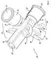
Figure 1 is a three-dimensional perspective view from above of an example of embodiment of the removable connector for peristaltic pump, according to the present invention; -
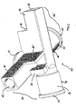
Figure 2 is a similar view to the one ofFig. 1 , but seen in perspective from below; -
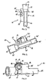
Figure 3 is a plan view from above and in minor scale of the removable connector for peristaltic pump ofFig. 1 ; -
Figure 4 is a plan view from below of the removable connector for peristaltic pump ofFig. 3 ; -
Figures. 5 and 6 are sectional views, according to the lines V-V and VI-VI ofFig. 4 , respectively; -
Figure 7 is a view in the direction of the arrow VII ofFigure 4 ; -
Figure 8 is a plan view from above of a peristaltic pump, in the stator seat of which the removable connector according to the invention is applied. - First of all, with reference to
Figure 8 , letter P indicates as a whole a peristaltic pump comprising a stator, having a pump seat S formed in the same, and a rotor R, which acts on a flexible pipe F, housed in an arcuate manner inside said pump seat S, and that is in turn fixed in said seat S by means of aremovable connector 10, subject of the present invention. - Said
removable connector 10 realizes the hydraulic connection between said flexible pipe F inside said seat S, and two flexible pipes T, T' external to said seat S, for the feed and delivery of a fluid, in particular human blood. Said internal pipe F has a larger diameter than the one of said flexible pipes T, T'. - Said
removable connector 10 is made of elastically flexible plastic material. - The stator carter of said peristaltic pump P has, in said seat S, a lateral opening A, delimited by two different-shaped fixing housings M, M', to permit the housing of said
removable connector 10. - In particular, said housing M is made with profile of a curvilinear arc, while the housing M' is made with angular configuration.
- With reference to
Figures 1 and2 , saidremovable connector 10 comprises twotubular sections 11, 11', mutually superimposed and in a single body (refer toFigures 5 and 6 ). - As can be clearly seen also from
Figure 4 , the axis of said twotubular sections 11, 11', in plan view, form a substantially X-shaped configuration (refer toFigures 3 and 4 ), wherein each of saidtubular sections 11, 11', comprises: - a
first end 12, 12' including acylindrical cavity 13, 13' of larger diameter, end which - when saidconnector 10 is housed in said opening A of said seat S - is located inside said seat S and wherein there is fixed, with seal, a respective end of said flexible pipe of larger diameter F; - a
second end 14, 14', which - when saidconnector 10 is housed in said opening A of said seat S - is partly external with respect to said seat S, and includes acylindrical cavity 15, 15' of lesser diameter with respect to that of said first end, and wherein there is fixed with seal an end of a respective of said flexible pipes of lesser diameter T, T'. - Each pair of ends of said
tubular sections 11, 11', formed by a first and by a second of saidends 12/14', 12'/14 of the one and of the othertubular section 11, 11', provides, respectively, a substantially V-shapedelastic clamp 16, 16', which - when saidconnector 10 is housed in said opening A of said seat S - elastically surrounds a respective of said fixing housings M, M', maintaining stably in position the sameremovable connector 10, as a result of bilateral elastic clamping. - Said substantially V-shaped
elastic clamps 16, 16' have each other a mirror image symmetry with respect to the vertical median plane of the X-shaped configuration formed by the axes of thetubular sections 11, 11' of saidremovable connector 10. Saidremovable connector 10 further comprises afinger projection 18, provided on one of saidsecond ends 14, and which - when saidconnector 10 is accurately housed in said opening A, engages from below a corresponding protrusion of the fixing housing M' (Figure 8 ), improving the fixing stability of the sameremovable connector 10 between said housings M, M' of the pump P. - In order to improve the structural robustness of said
removable connector 10, saidsecond ends 14, 14' also have integrated stiffening projections, 19, protruding upwards and 19', protruding downward. - On the other hand, in order to facilitate correct positioning of said
removable connector 10 in said opening A of the seat S, between said housings M, M', in the upper part of one of said second ends 14', there is provided afixed button 17, on which the operator intuitively practices a downward pressure, when installing theconnector 10. - In addition, in order to provide a further grant of correct operational positioning of said
removable connector 10, one of said second ends 14' is provided, in its inferior part, with an integratedpin 20 protruding downward and that, when saidremovable connector 10 is correctly positioned, is inserted in a corresponding hole (not shown) provided in said pump seat S. When the insertion of saidpin 20 in said hole is realized, the operator is provided with the confirmation that the correct positioning and stable insertion of saidremovable connector 10 in said opening A of said pump seat S, between said housings M, M', have happened, and so it is possible to proceed with the starting up of the peristaltic pump in safety conditions. - The stable positioning of said
connector 10 in said opening A of said seat S as a consequence of bilateral elastic clamp of theend 12/14', 12'/14 pairs, is also easily detachable by manual extraction of thesame connector 10 from above with respect to said seat S. Considering the foregoing description, the steps of stable positioning and decomposition of saidremovable connector 10 with respect to the housings M, M' of the pump seat S, are evident and so are not further described. - Thus, said
removable connector 10 according to the invention comprises, as evident from what is written and illustrated, a structure that permits an easy, fast and safe insertion and following decomposition of the same with respect to the pump seat S, able to allow the operator to operate with fast manoeuvres and in safe conditions. - Further, said
removable connector 10 has a simplified structure, with relatively low costs. - As will be clear from the foregoing, the present invention allows the objects set forth in the introduction of the present description to be achieved in a simple and effective manner.
Claims (5)
- Peristaltic pump comprising a removable connector (10), made of elastically flexible plastic material, for hydraulic connection between a flexible pipe (F), housed in an arcuate manner inside a seat (S) of a peristaltic pump (P), and two flexible pipes (T, T') external to said seat (S), for the feed and delivery of a fluid, respectively, said removable connector (10) being positioned between two opposed fixing housings (M, M'), provided in a lateral opening (A) of said seat (S),
said removable connector (10) comprises two tubular sections (11, 11'), mutually superimposed and in a single body, wherein the axes, in plan view, form a substantially X-shaped configuration, characterized in that each of said tubular sections (11, 11'), comprises:- a first end (12, 12') including a cylindrical cavity (13, 13') of larger diameter; end which - when said connector (10) is housed in said opening (A) of said seat (S)- is located inside said seat (S) and wherein there is fixed, with seal, a respective end of said flexible pipe of larger diameter (F);- a second end (14, 14'), which - when said connector (10) is housed in said opening (A) of said seat (S)- is partly external with respect to said seat (S), and includes a cylindrical cavity (15, 15') of lesser diameter with respect to that of said first end, and wherein there is fixed with seal an end of a respective of said flexible pipes of lesser diameter (T, T'),and in that
each pair of ends of said tubular sections (11, 11') formed by a first and by a second of said ends (12/14', 12'/14) of the one and of the other tubular section (11, 11'), provides a substantially V-shaped elastic clamp (16, 16'), which - when said connector (10) is housed in said opening (A) of said seat (S)- elastically surrounds a respective of said fixing housings (M, M'), maintaining stably in position the same removable connector (10),
as a result of bilateral elastic clamping easily detachable by manual extraction of said connector (10) from above with respect to said seat (S). - Peristaltic pump comprising a removable connector (10) according to claim 1, characterized in that it comprises a projection (18), provided on one of said second ends (14, 14'), and which - when said connector (10) is housed in said opening (A) of said seat (S)- engages from below a corresponding protrusion of one of said fixing housings (M, M'), improving the fixing stability of the removable connector (10) between said housings (M, M').
- Peristaltic pump comprising a removable connector (10) according to claim 1 and/or 2, characterized in that on one of said second ends (14') there is provided a fixed button (17) to facilitate correct positioning of the removable connector (10) between said housings (M, M').
- Peristaltic pump comprising a removable connector (10) according to any one of the preceding claims, characterized in that at least one of said second ends (14, 14') has at least one integrated stiffening projection (19, 19').
- Peristaltic pump comprising a removable connector (10) according to claim 1, characterized in that said substantially V-shaped elastic clamps (16, 16') have mirror image symmetry with respect to the vertical median plane of the X-shaped configuration formed by the axes of the tubular sections 11, 11' of said removable connector 10.
Applications Claiming Priority (1)
| Application Number | Priority Date | Filing Date | Title |
|---|---|---|---|
| IT000386A ITTO20120386A1 (en) | 2012-04-30 | 2012-04-30 | REMOVABLE FITTING FOR PERISTALTIC PUMP |
Publications (2)
| Publication Number | Publication Date |
|---|---|
| EP2660470A1 EP2660470A1 (en) | 2013-11-06 |
| EP2660470B1 true EP2660470B1 (en) | 2015-01-21 |
Family
ID=46321361
Family Applications (1)
| Application Number | Title | Priority Date | Filing Date |
|---|---|---|---|
| EP20130002221 Active EP2660470B1 (en) | 2012-04-30 | 2013-04-26 | Removable connector for peristaltic pump |
Country Status (3)
| Country | Link |
|---|---|
| EP (1) | EP2660470B1 (en) |
| ES (1) | ES2535182T3 (en) |
| IT (1) | ITTO20120386A1 (en) |
Cited By (1)
| Publication number | Priority date | Publication date | Assignee | Title |
|---|---|---|---|---|
| EP4438102A1 (en) | 2023-03-31 | 2024-10-02 | Fresenius Medical Care Deutschland GmbH | Connector for connecting a pump hose segment to a pump bed of a peristaltic pump |
Family Cites Families (2)
| Publication number | Priority date | Publication date | Assignee | Title |
|---|---|---|---|---|
| ES2356026T3 (en) * | 2004-05-14 | 2011-04-04 | Fresenius Medical Care Deutschland Gmbh | ROLLER PUMP. |
| JP5397747B2 (en) * | 2009-02-16 | 2014-01-22 | ニプロ株式会社 | Tube pump |
-
2012
- 2012-04-30 IT IT000386A patent/ITTO20120386A1/en unknown
-
2013
- 2013-04-26 EP EP20130002221 patent/EP2660470B1/en active Active
- 2013-04-26 ES ES13002221.3T patent/ES2535182T3/en active Active
Cited By (2)
| Publication number | Priority date | Publication date | Assignee | Title |
|---|---|---|---|---|
| EP4438102A1 (en) | 2023-03-31 | 2024-10-02 | Fresenius Medical Care Deutschland GmbH | Connector for connecting a pump hose segment to a pump bed of a peristaltic pump |
| WO2024200388A1 (en) | 2023-03-31 | 2024-10-03 | Fresenius Medical Care Deutschland Gmbh | A connector for connecting a pump hose segment to a pump bed of a peristaltic pump |
Also Published As
| Publication number | Publication date |
|---|---|
| EP2660470A1 (en) | 2013-11-06 |
| ITTO20120386A1 (en) | 2013-10-31 |
| ES2535182T3 (en) | 2015-05-06 |
Similar Documents
| Publication | Publication Date | Title |
|---|---|---|
| US9496637B2 (en) | Vehicle-side connector | |
| US8777275B2 (en) | Fluid transfer connection device, circuit incorporating it and its mounting/demounting | |
| EP3007285B1 (en) | Electrical connector | |
| EP2930793B1 (en) | Connector | |
| EP2584206A1 (en) | Clamp | |
| KR20120110028A (en) | Connector position assurance device | |
| EP2660470B1 (en) | Removable connector for peristaltic pump | |
| US9722353B2 (en) | Connector with alignment function | |
| KR20160118145A (en) | Electrical connector | |
| EP1859994A2 (en) | Connector and mirror angle adjustment device | |
| US9004932B2 (en) | Connector having a sealing ring with projections positioned in recesses on an inner periphery of a tubular fitting | |
| JP6380185B2 (en) | Fuel injection valve clip and fuel injection valve unit | |
| KR20150004438U (en) | Bushing unit for pipe connecting applied at pipe rack system | |
| US10218120B2 (en) | Connector device | |
| EP2587593B1 (en) | Electrical connector assembly with integrated wire holding means | |
| EP3048934B1 (en) | Flowerport comprising adjustable arms for coupling and supporting to railings, walls or other supports | |
| US9509078B2 (en) | Connector housing | |
| KR20090022961A (en) | Connector housing | |
| KR101143590B1 (en) | Female connector of one touch attaching or one touch detaching type | |
| JP5703982B2 (en) | Connector mounting structure | |
| CN109594301A (en) | Cable fastening structure and washing machine including it | |
| EP1887663A1 (en) | Dummy plug for option device electric connector in heavy construction equipment | |
| CN211776943U (en) | Connect angle sign indicating number and door and window frame body | |
| US8961244B2 (en) | Terminal fitting and bulb socket | |
| JP6047449B2 (en) | Shunt cap |
Legal Events
| Date | Code | Title | Description |
|---|---|---|---|
| PUAI | Public reference made under article 153(3) epc to a published international application that has entered the european phase |
Free format text: ORIGINAL CODE: 0009012 |
|
| AK | Designated contracting states |
Kind code of ref document: A1 Designated state(s): AL AT BE BG CH CY CZ DE DK EE ES FI FR GB GR HR HU IE IS IT LI LT LU LV MC MK MT NL NO PL PT RO RS SE SI SK SM TR |
|
| AX | Request for extension of the european patent |
Extension state: BA ME |
|
| 17P | Request for examination filed |
Effective date: 20140425 |
|
| RBV | Designated contracting states (corrected) |
Designated state(s): AL AT BE BG CH CY CZ DE DK EE ES FI FR GB GR HR HU IE IS IT LI LT LU LV MC MK MT NL NO PL PT RO RS SE SI SK SM TR |
|
| GRAP | Despatch of communication of intention to grant a patent |
Free format text: ORIGINAL CODE: EPIDOSNIGR1 |
|
| INTG | Intention to grant announced |
Effective date: 20140904 |
|
| GRAS | Grant fee paid |
Free format text: ORIGINAL CODE: EPIDOSNIGR3 |
|
| GRAA | (expected) grant |
Free format text: ORIGINAL CODE: 0009210 |
|
| AK | Designated contracting states |
Kind code of ref document: B1 Designated state(s): AL AT BE BG CH CY CZ DE DK EE ES FI FR GB GR HR HU IE IS IT LI LT LU LV MC MK MT NL NO PL PT RO RS SE SI SK SM TR |
|
| REG | Reference to a national code |
Ref country code: GB Ref legal event code: FG4D |
|
| REG | Reference to a national code |
Ref country code: CH Ref legal event code: EP |
|
| REG | Reference to a national code |
Ref country code: IE Ref legal event code: FG4D |
|
| REG | Reference to a national code |
Ref country code: DE Ref legal event code: R096 Ref document number: 602013000852 Country of ref document: DE Effective date: 20150305 |
|
| REG | Reference to a national code |
Ref country code: AT Ref legal event code: REF Ref document number: 709324 Country of ref document: AT Kind code of ref document: T Effective date: 20150315 |
|
| REG | Reference to a national code |
Ref country code: ES Ref legal event code: FG2A Ref document number: 2535182 Country of ref document: ES Kind code of ref document: T3 Effective date: 20150506 |
|
| REG | Reference to a national code |
Ref country code: SE Ref legal event code: TRGR |
|
| REG | Reference to a national code |
Ref country code: AT Ref legal event code: MK05 Ref document number: 709324 Country of ref document: AT Kind code of ref document: T Effective date: 20150121 |
|
| REG | Reference to a national code |
Ref country code: GR Ref legal event code: EP Ref document number: 20150400772 Country of ref document: GR Effective date: 20150518 |
|
| REG | Reference to a national code |
Ref country code: LT Ref legal event code: MG4D |
|
| PG25 | Lapsed in a contracting state [announced via postgrant information from national office to epo] |
Ref country code: LT Free format text: LAPSE BECAUSE OF FAILURE TO SUBMIT A TRANSLATION OF THE DESCRIPTION OR TO PAY THE FEE WITHIN THE PRESCRIBED TIME-LIMIT Effective date: 20150121 Ref country code: BG Free format text: LAPSE BECAUSE OF FAILURE TO SUBMIT A TRANSLATION OF THE DESCRIPTION OR TO PAY THE FEE WITHIN THE PRESCRIBED TIME-LIMIT Effective date: 20150421 Ref country code: FI Free format text: LAPSE BECAUSE OF FAILURE TO SUBMIT A TRANSLATION OF THE DESCRIPTION OR TO PAY THE FEE WITHIN THE PRESCRIBED TIME-LIMIT Effective date: 20150121 Ref country code: HR Free format text: LAPSE BECAUSE OF FAILURE TO SUBMIT A TRANSLATION OF THE DESCRIPTION OR TO PAY THE FEE WITHIN THE PRESCRIBED TIME-LIMIT Effective date: 20150121 Ref country code: NO Free format text: LAPSE BECAUSE OF FAILURE TO SUBMIT A TRANSLATION OF THE DESCRIPTION OR TO PAY THE FEE WITHIN THE PRESCRIBED TIME-LIMIT Effective date: 20150421 |
|
| PG25 | Lapsed in a contracting state [announced via postgrant information from national office to epo] |
Ref country code: IS Free format text: LAPSE BECAUSE OF FAILURE TO SUBMIT A TRANSLATION OF THE DESCRIPTION OR TO PAY THE FEE WITHIN THE PRESCRIBED TIME-LIMIT Effective date: 20150521 Ref country code: RS Free format text: LAPSE BECAUSE OF FAILURE TO SUBMIT A TRANSLATION OF THE DESCRIPTION OR TO PAY THE FEE WITHIN THE PRESCRIBED TIME-LIMIT Effective date: 20150121 Ref country code: PL Free format text: LAPSE BECAUSE OF FAILURE TO SUBMIT A TRANSLATION OF THE DESCRIPTION OR TO PAY THE FEE WITHIN THE PRESCRIBED TIME-LIMIT Effective date: 20150121 Ref country code: LV Free format text: LAPSE BECAUSE OF FAILURE TO SUBMIT A TRANSLATION OF THE DESCRIPTION OR TO PAY THE FEE WITHIN THE PRESCRIBED TIME-LIMIT Effective date: 20150121 Ref country code: AT Free format text: LAPSE BECAUSE OF FAILURE TO SUBMIT A TRANSLATION OF THE DESCRIPTION OR TO PAY THE FEE WITHIN THE PRESCRIBED TIME-LIMIT Effective date: 20150121 |
|
| REG | Reference to a national code |
Ref country code: DE Ref legal event code: R097 Ref document number: 602013000852 Country of ref document: DE |
|
| PG25 | Lapsed in a contracting state [announced via postgrant information from national office to epo] |
Ref country code: RO Free format text: LAPSE BECAUSE OF FAILURE TO SUBMIT A TRANSLATION OF THE DESCRIPTION OR TO PAY THE FEE WITHIN THE PRESCRIBED TIME-LIMIT Effective date: 20150121 Ref country code: DK Free format text: LAPSE BECAUSE OF FAILURE TO SUBMIT A TRANSLATION OF THE DESCRIPTION OR TO PAY THE FEE WITHIN THE PRESCRIBED TIME-LIMIT Effective date: 20150121 Ref country code: SK Free format text: LAPSE BECAUSE OF FAILURE TO SUBMIT A TRANSLATION OF THE DESCRIPTION OR TO PAY THE FEE WITHIN THE PRESCRIBED TIME-LIMIT Effective date: 20150121 Ref country code: CZ Free format text: LAPSE BECAUSE OF FAILURE TO SUBMIT A TRANSLATION OF THE DESCRIPTION OR TO PAY THE FEE WITHIN THE PRESCRIBED TIME-LIMIT Effective date: 20150121 Ref country code: EE Free format text: LAPSE BECAUSE OF FAILURE TO SUBMIT A TRANSLATION OF THE DESCRIPTION OR TO PAY THE FEE WITHIN THE PRESCRIBED TIME-LIMIT Effective date: 20150121 |
|
| PLBE | No opposition filed within time limit |
Free format text: ORIGINAL CODE: 0009261 |
|
| STAA | Information on the status of an ep patent application or granted ep patent |
Free format text: STATUS: NO OPPOSITION FILED WITHIN TIME LIMIT |
|
| PG25 | Lapsed in a contracting state [announced via postgrant information from national office to epo] |
Ref country code: LU Free format text: LAPSE BECAUSE OF FAILURE TO SUBMIT A TRANSLATION OF THE DESCRIPTION OR TO PAY THE FEE WITHIN THE PRESCRIBED TIME-LIMIT Effective date: 20150426 Ref country code: MC Free format text: LAPSE BECAUSE OF FAILURE TO SUBMIT A TRANSLATION OF THE DESCRIPTION OR TO PAY THE FEE WITHIN THE PRESCRIBED TIME-LIMIT Effective date: 20150121 |
|
| 26N | No opposition filed |
Effective date: 20151022 |
|
| REG | Reference to a national code |
Ref country code: IE Ref legal event code: MM4A |
|
| PG25 | Lapsed in a contracting state [announced via postgrant information from national office to epo] |
Ref country code: SI Free format text: LAPSE BECAUSE OF FAILURE TO SUBMIT A TRANSLATION OF THE DESCRIPTION OR TO PAY THE FEE WITHIN THE PRESCRIBED TIME-LIMIT Effective date: 20150121 |
|
| REG | Reference to a national code |
Ref country code: FR Ref legal event code: PLFP Year of fee payment: 4 |
|
| PG25 | Lapsed in a contracting state [announced via postgrant information from national office to epo] |
Ref country code: IE Free format text: LAPSE BECAUSE OF NON-PAYMENT OF DUE FEES Effective date: 20150426 |
|
| REG | Reference to a national code |
Ref country code: CH Ref legal event code: PL |
|
| PG25 | Lapsed in a contracting state [announced via postgrant information from national office to epo] |
Ref country code: MT Free format text: LAPSE BECAUSE OF FAILURE TO SUBMIT A TRANSLATION OF THE DESCRIPTION OR TO PAY THE FEE WITHIN THE PRESCRIBED TIME-LIMIT Effective date: 20150121 |
|
| PG25 | Lapsed in a contracting state [announced via postgrant information from national office to epo] |
Ref country code: CH Free format text: LAPSE BECAUSE OF NON-PAYMENT OF DUE FEES Effective date: 20160430 Ref country code: LI Free format text: LAPSE BECAUSE OF NON-PAYMENT OF DUE FEES Effective date: 20160430 |
|
| REG | Reference to a national code |
Ref country code: FR Ref legal event code: PLFP Year of fee payment: 5 |
|
| PG25 | Lapsed in a contracting state [announced via postgrant information from national office to epo] |
Ref country code: HU Free format text: LAPSE BECAUSE OF FAILURE TO SUBMIT A TRANSLATION OF THE DESCRIPTION OR TO PAY THE FEE WITHIN THE PRESCRIBED TIME-LIMIT; INVALID AB INITIO Effective date: 20130426 |
|
| PG25 | Lapsed in a contracting state [announced via postgrant information from national office to epo] |
Ref country code: CY Free format text: LAPSE BECAUSE OF FAILURE TO SUBMIT A TRANSLATION OF THE DESCRIPTION OR TO PAY THE FEE WITHIN THE PRESCRIBED TIME-LIMIT Effective date: 20150121 |
|
| PG25 | Lapsed in a contracting state [announced via postgrant information from national office to epo] |
Ref country code: TR Free format text: LAPSE BECAUSE OF FAILURE TO SUBMIT A TRANSLATION OF THE DESCRIPTION OR TO PAY THE FEE WITHIN THE PRESCRIBED TIME-LIMIT Effective date: 20150121 |
|
| REG | Reference to a national code |
Ref country code: FR Ref legal event code: PLFP Year of fee payment: 6 |
|
| PG25 | Lapsed in a contracting state [announced via postgrant information from national office to epo] |
Ref country code: SM Free format text: LAPSE BECAUSE OF FAILURE TO SUBMIT A TRANSLATION OF THE DESCRIPTION OR TO PAY THE FEE WITHIN THE PRESCRIBED TIME-LIMIT Effective date: 20150121 |
|
| PG25 | Lapsed in a contracting state [announced via postgrant information from national office to epo] |
Ref country code: MK Free format text: LAPSE BECAUSE OF FAILURE TO SUBMIT A TRANSLATION OF THE DESCRIPTION OR TO PAY THE FEE WITHIN THE PRESCRIBED TIME-LIMIT Effective date: 20150121 Ref country code: PT Free format text: LAPSE BECAUSE OF FAILURE TO SUBMIT A TRANSLATION OF THE DESCRIPTION OR TO PAY THE FEE WITHIN THE PRESCRIBED TIME-LIMIT Effective date: 20150121 |
|
| PG25 | Lapsed in a contracting state [announced via postgrant information from national office to epo] |
Ref country code: AL Free format text: LAPSE BECAUSE OF FAILURE TO SUBMIT A TRANSLATION OF THE DESCRIPTION OR TO PAY THE FEE WITHIN THE PRESCRIBED TIME-LIMIT Effective date: 20150121 |
|
| PGFP | Annual fee paid to national office [announced via postgrant information from national office to epo] |
Ref country code: NL Payment date: 20250430 Year of fee payment: 13 |
|
| PGFP | Annual fee paid to national office [announced via postgrant information from national office to epo] |
Ref country code: DE Payment date: 20250513 Year of fee payment: 13 |
|
| PGFP | Annual fee paid to national office [announced via postgrant information from national office to epo] |
Ref country code: GB Payment date: 20250521 Year of fee payment: 13 Ref country code: ES Payment date: 20250521 Year of fee payment: 13 |
|
| PGFP | Annual fee paid to national office [announced via postgrant information from national office to epo] |
Ref country code: BE Payment date: 20250430 Year of fee payment: 13 |
|
| PGFP | Annual fee paid to national office [announced via postgrant information from national office to epo] |
Ref country code: FR Payment date: 20250430 Year of fee payment: 13 |
|
| PGFP | Annual fee paid to national office [announced via postgrant information from national office to epo] |
Ref country code: GR Payment date: 20250428 Year of fee payment: 13 |
|
| PGFP | Annual fee paid to national office [announced via postgrant information from national office to epo] |
Ref country code: SE Payment date: 20250425 Year of fee payment: 13 |
|
| PGFP | Annual fee paid to national office [announced via postgrant information from national office to epo] |
Ref country code: IT Payment date: 20251030 Year of fee payment: 13 |