Technical field of the invention
-
The disclosure relates to the field of concrete pumps, in particular to a method for controlling a concrete pump to perform re-pumping after stopping and a method for controlling a concrete pump to perform reverse pumping after stopping.
Background of the invention
-
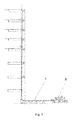
As shown in Figs. 1 and 2, a concrete pump includes a conveying pipe A for conveying concrete to the destination and a main machine part B, wherein the main machine part B of the concrete pump includes a hopper 18, a pair of concrete cylinders (a first concrete cylinder 20 and a second concrete cylinder 21), a pair of main cylinders (a first main cylinder 13 and a second main cylinder 14), an S-shaped distribution valve 17, a pair of oscillating cylinders (a first oscillating cylinder 11 and a second oscillating cylinder 12) and the like. The concrete cylinders are used for pumping concrete from the hopper to the conveying pipe and driven by the main cylinders alternately moving; the S-shaped distribution valve 17 is located in the hopper 18 and connected with the conveying pipe, and is further communicated with one of the concrete cylinders alternately to distribute concrete, and the other concrete cylinder sucks concrete from the hopper. Specifically, the alternate oscillation of the S-shaped distribution valve is implemented by one or more actuators (such as the oscillating cylinders).
-
In addition, the concrete pump further includes an accumulator and a constant-pressure pump. The accumulator provides a pressure impact to enable the S-shaped distribution valve to reach enough acceleration speed and speed during oscillation in order to ensure the coordination between the pumping action and the distribution pipe and enough flow. The actuator(s) is(are) mainly used for driving the gravity of the S-shaped distribution valve, the friction force between the S-shaped distribution valve and other mechanical parts, the cutting force of a concrete column in the S-shaped distribution valve and the resistance of the concrete in the hopper 18. The constant-pressure pump is used for providing pressure oil to the accumulator and determines the upper pressure limit of the accumulator. When the pressure of the accumulator is charged to the target value (called the pressure cutoff value of the constant-pressure pump), the output flow of the constant-pressure pump decreases automatically, even to 0; at the moment, the magnitude of the pressure in the accumulator is equal to the pressure cutoff value of the constant-pressure pump.
-
The working principle of the concrete pump is as follows:
- As shown in Fig. 2, the concrete pump may be in two working states: pumping, namely, conveying concrete to the destination to implement distribution, and reverse pumping, namely, recycling the concrete in the concrete conveying pipe to the hopper most possibly at the end of work or when some concrete is blocked in the conveying pipe.
-
The pumping logics of the concrete pump are as follows:
- when the first main cylinder 13 is propelled under the control of a control system, the first and second oscillating cylinders 11 and 12 drive the S-shaped distribution valve to be communicated with the first concrete cylinder 20 beside the first main cylinder 13; at the moment, the first main cylinder 13 pushes the concrete in the first concrete cylinder 20 to the S-shaped distribution valve, and the second main cylinder 14 sucks the concrete in the hopper 18 into the second concrete cylinder 21; when the two main cylinders move to a predetermined position, a conversion will be made as follows: when the second main cylinder 14 is propelled under the control of a power source and a control system, the oscillating cylinders drive the S-shaped distribution valve to be communicated with the second concrete cylinder 21 beside the second main cylinder 14; at the moment, the second main cylinder 14 pushes the concrete in the second concrete cylinder 21 into the S-shaped distribution valve, and the first main cylinder 13 sucks the concrete in the hopper 18 into the first concrete cylinder 20 till the two main cylinders move to the predetermined position again; and the system will repeat all the logics above. By such a concrete pump, the concrete in the hopper 18 is output to the S-shaped distribution valve continuously and then conveyed to the destination through the conveying pipe (as shown in Fig. 1).
-
The reverse pumping logics of the concrete pump are as follows:
- when the first main cylinder 13 is propelled under the control of a power source and a control system, the oscillating cylinders drive the S-shaped distribution valve 17 to be communicated with the second concrete cylinder 21 beside the second main cylinder 14; at the moment, the first main cylinder 13 pushes the concrete in the first concrete cylinder 20 to the hopper 18, and the second main cylinder 14 sucks the concrete in the S-shaped distribution valve into the second concrete cylinder 21; when the two main cylinders move to a predetermined position, a conversion will be made as follows: when the second main cylinder 14 is propelled under the control of a power source and a control system, the oscillating cylinders drive the S-shaped distribution valve 17 to be communicated with the first concrete cylinder 20 beside the first main cylinder 13; at the moment, the second main cylinder 14 pushes the concrete in the second concrete cylinder 21 into the hopper 18, and the first main cylinder 13 sucks the concrete in the S-shaped distribution valve into the first concrete cylinder 20 till the two main cylinders move to the predetermined position again; and the system will repeat all the logics above. By such a pumping mechanism, the concrete in the conveying pipe is sucked into the S-shaped distribution valve continuously and then sucked into the hopper 18 through the S-shaped distribution valve.
-
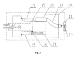
Fig. 3 shows a hydraulic control circuit for implementing the logics above; an electromagnetic reversing valve 1 and a small hydraulic reversing valve 2 are used for driving a large hydraulic reversing valve 3 to reverse and the large hydraulic reversing valve 3 is used for driving the main cylinders to reverse; and similarly, an electromagnetic reversing valve 8 and a small hydraulic reversing valve 9 are used for driving a large hydraulic reversing valve 10 to reverse and the large hydraulic reversing valve 10 is used for driving the oscillating cylinders to reverse, wherein the main cylinders include a first main cylinder 13 and a second main cylinder 14 and the oscillating cylinders include a first oscillating cylinder 11 and a second oscillating cylinder 12. A first oil pump 4 is used for driving the main cylinders; and a second oil pump 5 is used for driving the oscillating cylinders. The second oil pump 5 provides hydraulic oil to the accumulator 7, and the accumulator 7 drives the first and second oscillating cylinders 11 and 12 to oscillate.
-
In such a using environment that the concrete pump must stop for a certain time after working for a period of time and then works again, if the concrete pump is restarted after stopping in the prior art, the cylinders and the oscillating cylinders will drive actuating mechanisms to perform the following operation:
- if the concrete pump is re-started for pumping after the pumping is stopped:
- the pumping mechanism will pump and push concrete in the original moving direction continuously if not reaching the position of a reversing trigger signal, namely, if the first main cylinder 13 is propelled before the stopping, the S-shaped distribution valve is communicated with the first concrete cylinder 20 beside the first main cylinder 13, and after the pumping is started, the first main cylinder 13 will be propelled continuously and the concrete in the first concrete cylinder 20 is pushed to the conveying pipe through the S-shaped distribution valve continuously; and
- if reverse pumping is started after the pumping is stopped:
- if not reaching the position of the reversing trigger signal, the first main cylinder 13 and the second main cylinder 14 will keep the original moving direction, while the S-shaped distribution valve will switch the direction, namely, if the first main cylinder 13 is propelled and the S-shaped distribution valve is communicated with the first concrete cylinder 20 beside the first main cylinder 13 during the pumping, the first main cylinder 13 will be propelled continuously and the S-shaped distribution valve will be switched to the second concrete cylinder 21 beside the second main cylinder 14 and the second main cylinder 14 will move oppositely to the hopper 18 after the reverse pumping is started, so as to implement the logics of reverse pumping (the concrete in the conveying pipe and S-shaped distribution valve is sucked into the concrete cylinder through the second main cylinder 14, and the concrete in the first concrete cylinder 20 is pushed to the hopper 18 through the first main cylinder 13).
-
The prior art has the defects as follows:
- the control method easily causes pipe block-up and accelerated wearing of easily damaged parts. Specifically:
- Re-pumping after the pumping is stopped:
- it can be seen from Fig. 1 that a lot of concrete is still left in the conveying pipe when the pumping is stopped and may sink gradually under the action of its gravity and separate water out continuously, and partial water continuously flows out of the conveying pipe from the joint of the pipes in the stopping process, so that the condition of the concrete in the conveying pipe deteriorates; and under such condition, if the pumping is started at once, a large impact will be generated due to the resistance increase caused by the deterioration of the concrete, and the pipe may be blocked up directly in a terrible condition (the conveying pipe is blocked up by the concrete). The impact vibration and the pipe block-up may cause the accelerated wearing, power consumption and waste of cost of the whole machine.
- Reverse pumping after the pumping is stopped:
- this is a function operated frequently in the using process of machinery; and the oscillating cylinders will switch to another position at first and then perform reverse pumping in the prior art. As the analysis above, due to the separation of water, the initial set of concrete or the sinking of concrete under the action of its gravity, the concrete in the S-shaped distribution valve and the hopper 18 may deteriorate and increase in resistance, at the moment, the oscillating resistance of the S-shaped distribution valve also increases greatly, so that direct driving may cause a large impact, wearing and energy waste.
Summary of the invention
-
The technical problem to be solved by the disclosure is to provide a method for controlling a concrete pump to perform re-pumping after stopping and a method for controlling a concrete pump to perform reverse pumping after stopping, which can optimize the condition of the concrete and decrease the pumping resistance and the wearing of the whole machine.
-
In order to solve the technical problem, in one aspect, the disclosure provides a method for controlling a concrete pump to perform re-pumping after stopping, including: oscillating an S-shaped distribution valve in a hopper to enable the first end of the S-shaped distribution valve to leave an originally communicated concrete cylinder and to communicate with another concrete cylinder, and then, changing the moving directions of main cylinders with respect to that before the stopping to start to convey concrete to a conveying pipe through another concrete cylinder.
-
Furthermore, before the step of oscillating the S-shaped distribution valve in the hopper, the method further includes: keeping the S-shaped distribution valve immobile and changing the moving directions of the main cylinders to reversely pump concrete from the conveying pipe.
-
Furthermore, before the step of oscillating the S-shaped distribution valve in the hopper, the method further includes: determining whether the stopping period of the concrete pump is greater than a predetermined value a, if it is greater than or equal to the predetermined value a, keeping the S-shaped distribution valve immobile and changing the moving directions of the main cylinders to reversely pump concrete from the conveying pipe.
-
Furthermore, the step of conveying the concrete includes: a pumping step: pushing the concrete in the concrete cylinder communicated with the S-shaped distribution valve into the S-shaped distribution valve, and sucking the concrete in the hopper into the concrete cylinder communicated with the hopper simultaneously; when the main cylinders move to a predetermined position, pausing the pumping step and executing the oscillating step: oscillating the S-shaped distribution valve to enable the first end of the S-shaped distribution valve to alternate the concrete cylinder to be communicated; and returning to the pumping step after the oscillating step is completed.
-
Furthermore, the step of reversely pumping the concrete includes: a reverse pumping step: sucking the concrete in the S-shaped distribution valve into the concrete cylinder communicated with the S-shaped distribution valve, and pushing the concrete in the concrete cylinder communicated with the hopper into the hopper simultaneously.
-
Furthermore, when the piston rods of the main cylinders conveying the concrete move to enable position sensors on the main cylinders to be triggered, it is determined that the main cylinders move to the predetermined position.
-
In another aspect, the disclosure further provides a method for controlling a concrete pump to perform reverse pumping after stopping, including: keeping an S-shaped distribution valve in a hopper immobile and changing the moving directions of main cylinders to start to reversely pump concrete from a conveying pipe.
-
Furthermore, the step of reversely pumping the concrete from the conveying pipe includes: a reverse pumping step: sucking the concrete in the S-shaped distribution valve into the concrete cylinder communicated with the S-shaped distribution valve, and pushing the concrete in the concrete cylinder communicated with the hopper into the hopper simultaneously; when the main cylinders move to a predetermined position, pausing the reverse pumping step and executing an oscillating step: oscillating the S-shaped distribution valve to enable the first end of the S-shaped distribution valve to alternate the concrete cylinder to be communicated; and returning to the reverse pumping step after the oscillating step is completed.
-
Furthermore, when the piston rods of the main cylinders conveying the concrete move to enable position sensors on the main cylinders to be triggered, it is determined that the main cylinders move to the predetermined position.
-
The disclosure has the advantages as follows:
- 1. According to the method for controlling the concrete pump to perform re-pumping after stopping provided by the disclosure, the concrete in the hopper is stirred and mixed by the oscillation of the S-shaped distribution valve, conveyed by another concrete cylinder which is originally used for sucking the concrete and sucked by another concrete cylinder which is originally used for conveying the concrete, so that the original pressurized concrete cylinder switches to suction to release the pressure and improve the internal environment thereof; and in addition, due to the oscillation of the S-shaped distribution valve, the dry concrete therein refluxes under the action of gravity (the concrete cylinder is not full as the suction rate is less than 1), and the condition of the concrete to be conveyed in the concrete cylinder and S-shaped distribution valve is improved.
- 2. According to the method for controlling the concrete pump to perform reverse pumping after stopping provided by the disclosure, the moving directions of the main cylinders are changed at first to reversely pump concrete from the conveying pipe, so that the first oscillation of the S-shaped distribution valve is avoided, and accordingly, impact is avoided.
-
The disclosure further has other objectives, features and advantages besides those described above. The disclosure is further explained below with reference to the accompanying drawings in detail.
Brief description of the drawings
-
The drawings are to provide further understanding of the disclosure and constitute one part of the application, and the exemplary embodiments of the disclosure and the explanations thereof are intended to explain the disclosure, instead of improperly limiting the disclosure. In the drawings:
- Fig. 1 is a diagram showing the whole structure of a concrete pump;
- Fig. 2 is a diagram showing the structure of a concrete pump excluding a conveying pipe;
- Fig. 3 is a diagram showing a hydraulic control circuit of a concrete pump;
- Fig. 4 shows a flowchart of a method for controlling a concrete pump to perform re-pumping after stopping according to the first embodiment of the disclosure; and
- Fig. 5 shows a flowchart of a method for controlling a concrete pump to perform reverse pumping after stopping according to the first embodiment of the disclosure.
Detailed description of the embodiments
-
The embodiments of the disclosure will be described below in conjunction with the drawings in detail, but the disclosure can be implemented by various ways limited and covered by the claims.
-
As shown in Fig. 4, a method for controlling a concrete pump to perform re-pumping after stopping according to the first embodiment of the disclosure includes the following steps:
- Step 101: Determining whether the stopping period of the concrete pump is greater than a predetermined value a, wherein the predetermined value a is determined according to the specific condition of the concrete pump, such as 10min; and
if the stopping period of the concrete pump is less than the predetermined value a, sequentially executing Step 102 and Step 103. - Step 102: Oscillating an S-shaped distribution value 17 in a hopper 18 to enable the first end of the S-shaped distribution valve 17 to leave an originally communicated concrete cylinder and to be communicated with another concrete cylinder.
- Step 103: Changing the moving directions of main cylinders with respect to that before the stopping to start to convey concrete to a conveying pipe through another concrete cylinder.
After waiting for too long, the concrete in the conveying pipe, S-shaped distribution valve and connected concrete cylinder is compacted under the action of self weight, and may separate water out to deteriorate because of some sealing reasons, therefore, the improvement on the logics is to oscillate the S-shaped distribution valve to another concrete cylinder to perform re-pumping, which has the advantages as follows:1, the concrete in the hopper is stirred and mixed by the movement of the S-shaped distribution valve, the deteriorative concrete is loosened and the vibration and wearing in the working process are reduced; 2, the originally pressurized concrete cylinder switches to suction, so as to release the pressure and improve the condition of the concrete therein; and 3, the dry concrete in the S-shaped distribution valve refluxes under the action of gravity (the concrete cylinder is not full as the suction rate is less than 1), so as to improve the condition of the concrete to be conveyed in the concrete cylinder and pipe.
If the stopping period of the concrete pump is greater than the predetermined value a, Step 104, Step 105 and Step 106 are sequentially executed:
- Step 104: Keeping the S-shaped distribution valve 17 immobile and changing the moving directions of the main cylinders to reversely pump concrete from the conveying pipe.
- Step 105: Oscillating the S-shaped distribution value 17 to enable the first end of the S-shaped distribution valve 17 to leave the originally communicated concrete cylinder and to be communicated with another concrete cylinder.
- Step 106: Starting to convey concrete to the conveying pipe through another concrete cylinder.
-
The concrete in the concrete pipe, S-shaped distribution valve, concrete cylinder and hopper is decompressed or activated at first by reverse pumping, oscillating the S-shaped distribution valve and conveying the concrete sequentially; and then, the concrete in the S-shaped distribution valve is stirred again, so as to loosen the deteriorative concrete and reduce the vibration and wearing in the working process. Therefore, the condition of the concrete in the system is optimized greatly, and the pumping and oscillation resistance and the wearing of the whole machine are reduced. The problem of deteriorative concrete in the drivable range of the main cylinders can be solved by the scheme.
-
Preferably, in Step 103 and Step 106, the step of conveying the concrete to the conveying pipe includes:
- a pumping step: pushing the concrete in the concrete cylinder communicated with the S-shaped distribution valve 17 into the S-shaped distribution valve 17, and sucking the concrete in the hopper 18 into the concrete cylinder communicated with the hopper 18 simultaneously;
- when the main cylinders move to a predetermined position, pausing the pumping step and executing an oscillation step: oscillating the S-shaped distribution valve 17 to enable the first end of the S-shaped distribution valve 17 to alternate its communicated concrete cylinder; and
- returning to the pumping step after the oscillating step is completed, and repeating the control logics like this.
-
Preferably, in Step 104, the step of reversely pumping the concrete from the conveying pipe includes: a reverse pumping step: sucking the concrete in the S-shaped distribution valve 17 into the concrete cylinder communicated with the S-shaped distribution valve 17, and pushing the concrete in the concrete cylinder communicated with the hopper 18 into the hopper 18 simultaneously.
-
In addition, more preferably, in the step of conveying the concrete to the conveying pipe, when the piston rods of the main cylinders conveying the concrete move to enable position sensors on the main cylinders to be triggered, it is determined that the main cylinders move to the predetermined position. Specifically, as shown in Figs. 2 and 3, the first and second main cylinders 13 and 14 are provided with a first sensor 15 and a second sensor 16 respectively; for example, if the first sensor 15 is triggered when the first main cylinder 13 is propelled forwards to convey concrete to the S-shaped distribution valve 17 through the first concrete cylinder 20, it is determined that the two main cylinders move to the predetermined position, so that the pumping step is paused and executing the oscillating step; and then the pumping step is executed again.
-
Specifically, as shown in Fig. 3, if controlled by a hydraulic system, one sides of electromagnetic valves 1 and 8 are electrified during normal operation; it is assumed that the first main cylinder 13 and a first oscillating cylinder 11 move forwards at the moment, only if the first main cylinder 13 moves to trigger the first sensor 15, a hydraulic control signal is sent out to drive a small hydraulic reversing valve 9 to reverse, the small hydraulic reversing valve 9 drives a large hydraulic reversing valve 10 to reverse, the large hydraulic reversing valve 10 drives the first oscillating cylinder 11 to reverse, a second oscillating cylinder 12 is reversed to move forwards; at the moment, the S-shaped distribution valve 17 in Fig. 3 implements oscillation reversing; when the two oscillating cylinders are reversed, a small hydraulic reversing valve 2 is driven to reverse so as to drive a large hydraulic reversing valve 3 to reverse, at the moment, the main cylinders may reverse, namely, the first main cylinder 13 moves backwards and the second main cylinder 14 moves forwards till the second main cylinder 14 triggers the second sensor 16, and then the circulation is started again.
-
The large hydraulic reversing valves 3 and 10 can also be reversed by electrifying the two electromagnets of the electromagnetic valves 1 and 8 respectively so as to reverse the main cylinders, which achieves an auxiliary effect and is used for an electric control system to control reversing flexibly.
-
It should be understood that the second embodiment of the method for controlling the concrete pump to perform re-pumping after stopping can be implemented according to the specific condition of working, namely, only Step 102 and Step 103 are implemented, namely, oscillating the S-shaped distribution valve 17 in the hopper 18 to enable the first end of the S-shaped distribution valve 17 to leave the originally communicated concrete cylinder and to be communicated with another concrete cylinder; and then, changing the moving directions of the main cylinders with respect to that before the stopping to start to convey concrete to the conveying pipe through another concrete cylinder.
-
In addition, it should be further understood that the third embodiment of the method for controlling the concrete pump to perform re-pumping after stopping can be implemented according to the specific condition of working, namely, Step 104 is added before Step 105 based on the second embodiment: keeping the S-shaped distribution valve 17 immobile and changing the moving directions of the main cylinders to reversely pump concrete from the conveying pipe.
-
As shown in Fig. 5, a method for controlling a concrete pump to perform reverse pumping after stopping according to the first embodiment of the disclosure includes the following steps:
- Step 201: Keeping an S-shaped distribution valve 17 in a hopper 18 immobile and changing the moving directions of main cylinders to start to reversely pump concrete from a conveying pipe.
-
Preferably, in Step 201, the step of reversely pumping the concrete from the conveying pipe includes:
- a reverse pumping step: sucking the concrete in the S-shaped distribution valve 17 into the concrete cylinder communicated with the S-shaped distribution valve 17, and pushing the concrete in the concrete cylinder communicated with the hopper 18 into the hopper 18 simultaneously;
- when the main cylinders move to a predetermined position, pausing the reverse pumping step and executing an oscillation step, namely, oscillating the S-shaped distribution valve 17 to enable the first end of the S-shaped distribution valve 17 to alternate its communicated concrete cylinder; and
- returning to the reverse pumping step after the oscillating step is completed, and repeating the control logics like this.
-
A large vibration may be generated when the reverse pumping is started in the prior art. At the moment, a change is made that the concrete is pumped at first and then the cylinder are oscillated to reverse. The cylinder communicated with the conveying pipe switches to pumping concrete from pushing concrete before the reverse pumping, so that the disruption situation of cylinder oscillation for reverse pumping during pipe block-up is solved; furthermore, the reverse pumping capability is improved and the vibration and wearing of the whole machine are reduced.
-
In addition, more preferably, in the step of reversely pumping the concrete from the conveying pipe, when the piston rods of the main cylinders conveying the concrete to the hopper 18 move to enable the position sensors on the main cylinders to be triggered, it is determined that the main cylinders move to the predetermined position. Specifically, as shown in Figs. 2 and 3, the first and second main cylinders 13 and 14 are provided with a first sensor 22 and a second sensor 23 respectively; for example, if the first sensor 22 is triggered when the first main cylinder 13 is propelled forwards to convey concrete to the hopper 18 through the first concrete cylinder 20, it is determined that the two main cylinders move to the predetermined position, so that the reverse pumping step is paused and the oscillating step is executed; and then the reverse pumping step is executed again.
-
Specifically, if under the control of a hydraulic system, the control way is similar to the hydraulic control way of the method for controlling the concrete pump to perform re-pumping after stopping, thereby needing no further description.
-
The above are only preferred embodiments of the disclosure and not intended to limit the disclosure. For those skilled in the art, various modifications and changes can be made in the disclosure. Any modifications, equivalent replacements, improvements and the like within the spirit and principle of the disclosure shall fall within the scope of protection of the disclosure.