EP2660427A1 - Turbine system comprising a transition duct with a convolution seal - Google Patents
Turbine system comprising a transition duct with a convolution seal Download PDFInfo
- Publication number
- EP2660427A1 EP2660427A1 EP13156920.4A EP13156920A EP2660427A1 EP 2660427 A1 EP2660427 A1 EP 2660427A1 EP 13156920 A EP13156920 A EP 13156920A EP 2660427 A1 EP2660427 A1 EP 2660427A1
- Authority
- EP
- European Patent Office
- Prior art keywords
- outer leg
- transition duct
- turbine system
- seal
- convolution
- Prior art date
- Legal status (The legal status is an assumption and is not a legal conclusion. Google has not performed a legal analysis and makes no representation as to the accuracy of the status listed.)
- Granted
Links
- 230000007704 transition Effects 0.000 title claims abstract description 125
- 238000011144 upstream manufacturing Methods 0.000 claims description 3
- 239000007789 gas Substances 0.000 description 33
- 239000000446 fuel Substances 0.000 description 16
- 238000002485 combustion reaction Methods 0.000 description 10
- 239000012530 fluid Substances 0.000 description 10
- 238000007789 sealing Methods 0.000 description 3
- 238000003491 array Methods 0.000 description 2
- 230000008030 elimination Effects 0.000 description 2
- 238000003379 elimination reaction Methods 0.000 description 2
- VNWKTOKETHGBQD-UHFFFAOYSA-N methane Chemical compound C VNWKTOKETHGBQD-UHFFFAOYSA-N 0.000 description 2
- 238000012986 modification Methods 0.000 description 2
- 230000004048 modification Effects 0.000 description 2
- 230000015572 biosynthetic process Effects 0.000 description 1
- 230000008859 change Effects 0.000 description 1
- 238000001816 cooling Methods 0.000 description 1
- 238000010586 diagram Methods 0.000 description 1
- 238000004146 energy storage Methods 0.000 description 1
- 230000003993 interaction Effects 0.000 description 1
- 239000007788 liquid Substances 0.000 description 1
- 239000000463 material Substances 0.000 description 1
- 239000002184 metal Substances 0.000 description 1
- 229910001092 metal group alloy Inorganic materials 0.000 description 1
- 238000000034 method Methods 0.000 description 1
- 239000003345 natural gas Substances 0.000 description 1
- 239000007800 oxidant agent Substances 0.000 description 1
- 238000010248 power generation Methods 0.000 description 1
- 238000011084 recovery Methods 0.000 description 1
Images




Classifications
-
- F—MECHANICAL ENGINEERING; LIGHTING; HEATING; WEAPONS; BLASTING
- F01—MACHINES OR ENGINES IN GENERAL; ENGINE PLANTS IN GENERAL; STEAM ENGINES
- F01D—NON-POSITIVE DISPLACEMENT MACHINES OR ENGINES, e.g. STEAM TURBINES
- F01D9/00—Stators
- F01D9/02—Nozzles; Nozzle boxes; Stator blades; Guide conduits, e.g. individual nozzles
- F01D9/023—Transition ducts between combustor cans and first stage of the turbine in gas-turbine engines; their cooling or sealings
-
- F—MECHANICAL ENGINEERING; LIGHTING; HEATING; WEAPONS; BLASTING
- F23—COMBUSTION APPARATUS; COMBUSTION PROCESSES
- F23R—GENERATING COMBUSTION PRODUCTS OF HIGH PRESSURE OR HIGH VELOCITY, e.g. GAS-TURBINE COMBUSTION CHAMBERS
- F23R3/00—Continuous combustion chambers using liquid or gaseous fuel
- F23R3/002—Wall structures
-
- F—MECHANICAL ENGINEERING; LIGHTING; HEATING; WEAPONS; BLASTING
- F01—MACHINES OR ENGINES IN GENERAL; ENGINE PLANTS IN GENERAL; STEAM ENGINES
- F01D—NON-POSITIVE DISPLACEMENT MACHINES OR ENGINES, e.g. STEAM TURBINES
- F01D11/00—Preventing or minimising internal leakage of working-fluid, e.g. between stages
- F01D11/005—Sealing means between non relatively rotating elements
-
- F—MECHANICAL ENGINEERING; LIGHTING; HEATING; WEAPONS; BLASTING
- F05—INDEXING SCHEMES RELATING TO ENGINES OR PUMPS IN VARIOUS SUBCLASSES OF CLASSES F01-F04
- F05D—INDEXING SCHEME FOR ASPECTS RELATING TO NON-POSITIVE-DISPLACEMENT MACHINES OR ENGINES, GAS-TURBINES OR JET-PROPULSION PLANTS
- F05D2240/00—Components
- F05D2240/55—Seals
-
- F—MECHANICAL ENGINEERING; LIGHTING; HEATING; WEAPONS; BLASTING
- F05—INDEXING SCHEMES RELATING TO ENGINES OR PUMPS IN VARIOUS SUBCLASSES OF CLASSES F01-F04
- F05D—INDEXING SCHEME FOR ASPECTS RELATING TO NON-POSITIVE-DISPLACEMENT MACHINES OR ENGINES, GAS-TURBINES OR JET-PROPULSION PLANTS
- F05D2250/00—Geometry
- F05D2250/10—Two-dimensional
- F05D2250/18—Two-dimensional patterned
- F05D2250/183—Two-dimensional patterned zigzag
-
- F—MECHANICAL ENGINEERING; LIGHTING; HEATING; WEAPONS; BLASTING
- F05—INDEXING SCHEMES RELATING TO ENGINES OR PUMPS IN VARIOUS SUBCLASSES OF CLASSES F01-F04
- F05D—INDEXING SCHEME FOR ASPECTS RELATING TO NON-POSITIVE-DISPLACEMENT MACHINES OR ENGINES, GAS-TURBINES OR JET-PROPULSION PLANTS
- F05D2300/00—Materials; Properties thereof
- F05D2300/10—Metals, alloys or intermetallic compounds
-
- F—MECHANICAL ENGINEERING; LIGHTING; HEATING; WEAPONS; BLASTING
- F05—INDEXING SCHEMES RELATING TO ENGINES OR PUMPS IN VARIOUS SUBCLASSES OF CLASSES F01-F04
- F05D—INDEXING SCHEME FOR ASPECTS RELATING TO NON-POSITIVE-DISPLACEMENT MACHINES OR ENGINES, GAS-TURBINES OR JET-PROPULSION PLANTS
- F05D2300/00—Materials; Properties thereof
- F05D2300/50—Intrinsic material properties or characteristics
- F05D2300/501—Elasticity
Definitions
- the subject matter disclosed herein relates generally to turbine systems, and more particularly to seals between adjacent transition ducts of turbine systems.
- Turbine systems are widely utilized in fields such as power generation.
- a conventional gas turbine system includes a compressor section, a combustor section, and at least one turbine section.
- the compressor section is configured to compress air as the air flows through the compressor section.
- the air is then flowed from the compressor section to the combustor section, where it is mixed with fuel and combusted, generating a hot gas flow.
- the hot gas flow is provided to the turbine section, which utilizes the hot gas flow by extracting energy from it to power the compressor, an electrical generator, and other various loads.
- the combustor sections of turbine systems generally include tubes or ducts for flowing the combusted hot gas therethrough to the turbine section or sections.
- combustor sections have been introduced which include tubes or ducts that shift the flow of the hot gas.
- ducts for combustor sections have been introduced that, while flowing the hot gas longitudinally therethrough, additionally shift the flow radially or tangentially such that the flow has various angular components.
- connection of these ducts to each other is of increased concern.
- the ducts do not simply extend along a longitudinal axis, but are rather shifted off-axis from the inlet of the duct to the outlet of the duct, thermal expansion of the ducts can cause undesirable shifts in the ducts along or about various axes. Such shifts can cause unexpected gaps between the adjacent ducts, thus undesirably allowing leakage and mixing of cooling air and hot gas.
- an airfoil trailing edge is formed by adjacent ducts.
- This airfoil may shift the hot gas flow in the ducts, and thus eliminate the need for first stage nozzles.
- any gaps between the ducts can allow leakage and mixing which can interfere with the performance of the airfoil.
- an improved seal between adjacent combustor ducts in a turbine system would be desired in the art.
- a seal that allows for thermal growth of the adjacent ducts while preventing gaps between the adjacent ducts would be advantageous.
- the invention resides in a turbine system.
- the turbine system includes a transition duct.
- the transition duct includes an inlet, an outlet, and a passage extending between the inlet and the outlet and defining a longitudinal axis, a radial axis, and a tangential axis.
- the outlet of the transition duct is offset from the inlet along the longitudinal axis and the tangential axis.
- the transition duct further includes an interface feature for interfacing with an adjacent transition duct.
- the turbine system further includes a convolution seal contacting the interface feature to provide a seal between the interface feature and the adjacent transition duct.
- a turbine system in another aspect, includes a plurality of transition ducts disposed in a generally annular array.
- Each of the plurality of transition ducts includes an inlet, an outlet, and a passage extending between the inlet and the outlet and defining a longitudinal axis, a radial axis, and a tangential axis.
- the outlet of the transition duct is offset from the inlet along the longitudinal axis and the tangential axis.
- Each of the plurality of transition ducts further includes a first interface feature and a second interface feature.
- the turbine system further includes a plurality of convolution seals. Each of the plurality of convolution seals contacts and provides a seal between a first interface feature of one of the plurality of transition ducts and a second interface feature of an adjacent one of the plurality of transition ducts.
- FIG. 1 is a schematic diagram of a gas turbine system 10. It should be understood that the turbine system 10 of the present disclosure need not be a gas turbine system 10, but rather may be any suitable turbine system 10, such as a steam turbine system or other suitable system.
- the gas turbine system 10 may include a compressor section 12, a combustor section 14 which may include a plurality of combustors 15 as discussed below, and a turbine section 16.
- the compressor section 12 and turbine section 16 may be coupled by a shaft 18.
- the shaft 18 may be a single shaft or a plurality of shaft segments coupled together to form shaft 18.
- the shaft 18 may further be coupled to a generator or other suitable energy storage device, or may be connected directly to, for example, an electrical grid. Exhaust gases from the system 10 may be exhausted into the atmosphere, flowed to a steam turbine or other suitable system, or recycled through a heat recovery steam generator.
- the gas turbine system 10 as shown in FIG. 2 comprises a compressor section 12 for pressurizing a working fluid, discussed below, that is flowing through the system 10.
- Pressurized working fluid discharged from the compressor section 12 flows into a combustor section 14, which may include a plurality of combustors 15 (only one of which is illustrated in FIG. 2 ) disposed in an annular array about an axis of the system 10.
- the working fluid entering the combustor section 14 is mixed with fuel, such as natural gas or another suitable liquid or gas, and combusted. Hot gases of combustion flow from each combustor 15 to a turbine section 16 to drive the system 10 and generate power.
- a combustor 15 in the gas turbine 10 may include a variety of components for mixing and combusting the working fluid and fuel.
- the combustor 15 may include a casing 21, such as a compressor discharge casing 21.
- a variety of sleeves, which may be axially extending annular sleeves, may be at least partially disposed in the casing 21.
- the sleeves extend axially along a generally longitudinal axis 98, such that the inlet of a sleeve is axially aligned with the outlet.
- a combustor liner 22 may generally define a combustion zone 24 therein. Combustion of the working fluid, fuel, and optional oxidizer may generally occur in the combustion zone 24.
- the resulting hot gases of combustion may flow generally axially along the longitudinal axis 98 downstream through the combustion liner 22 into a transition piece 26, and then flow generally axially along the longitudinal axis 98 through the transition piece 26 and into the turbine section 16.
- the combustor 15 may further include a fuel nozzle 40 or a plurality of fuel nozzles 40. Fuel may be supplied to the fuel nozzles 40 by one or more manifolds (not shown). As discussed below, the fuel nozzle 40 or fuel nozzles 40 may supply the fuel and, optionally, working fluid to the combustion zone 24 for combustion.
- a combustor 15 may include one or more transition ducts 50.
- the transition ducts 50 of the present disclosure may be provided in place of various axially extending sleeves of other combustors.
- a transition duct 50 may replace the axially extending transition piece 26 and, optionally, the combustor liner 22 of a combustor 15.
- the transition duct may extend from the fuel nozzles 40, or from the combustor liner 22.
- the transition duct 50 may provide various advantages over the axially extending combustor liners 22 and transition pieces 26 for flowing working fluid therethrough and to the turbine section 16.
- the plurality of transition ducts 50 may be disposed in an annular array about a longitudinal axis 90. Further, each transition duct 50 may extend between a fuel nozzle 40 or plurality of fuel nozzles 40 and the turbine section 16. For example, each transition duct 50 may extend from the fuel nozzles 40 to the turbine section 16. Thus, working fluid may flow generally from the fuel nozzles 40 through the transition duct 50 to the turbine section 16. In some embodiments, the transition ducts 50 may advantageously allow for the elimination of the first stage nozzles in the turbine section, which may eliminate any associated drag and pressure drop and increase the efficiency and output of the system 10.
- Each transition duct 50 may have an inlet 52, an outlet 54, and a passage 56 therebetween.
- the inlet 52 and outlet 54 of a transition duct 50 may have generally circular or oval cross-sections, rectangular cross-sections, triangular cross-sections, or any other suitable polygonal cross-sections. Further, it should be understood that the inlet 52 and outlet 54 of a transition duct 50 need not have similarly shaped cross-sections.
- the inlet 52 may have a generally circular cross-section, while the outlet 54 may have a generally rectangular cross-section.
- the passage 56 may be generally tapered between the inlet 52 and the outlet 54.
- at least a portion of the passage 56 may be generally conically shaped.
- the passage 56 or any portion thereof may have a generally rectangular cross-section, triangular cross-section, or any other suitable polygonal cross-section. It should be understood that the cross-sectional shape of the passage 56 may change throughout the passage 56 or any portion thereof as the passage 56 tapers from the relatively larger inlet 52 to the relatively smaller outlet 54.
- the outlet 54 of each of the plurality of transition ducts 50 may be offset from the inlet 52 of the respective transition duct 50.
- offset means spaced from along the identified coordinate direction.
- the outlet 54 of each of the plurality of transition ducts 50 may be longitudinally offset from the inlet 52 of the respective transition duct 50, such as offset along the longitudinal axis 90.
- the outlet 54 of each of the plurality of transition ducts 50 may be tangentially offset from the inlet 52 of the respective transition duct 50, such as offset along a tangential axis 92. Because the outlet 54 of each of the plurality of transition ducts 50 is tangentially offset from the inlet 52 of the respective transition duct 50, the transition ducts 50 may advantageously utilize the tangential component of the flow of working fluid through the transition ducts 50 to eliminate the need for first stage nozzles in the turbine section 16, as discussed below.
- the outlet 54 of each of the plurality of transition ducts 50 may be radially offset from the inlet 52 of the respective transition duct 50, such as offset along a radial axis 94. Because the outlet 54 of each of the plurality of transition ducts 50 is radially offset from the inlet 52 of the respective transition duct 50, the transition ducts 50 may advantageously utilize the radial component of the flow of working fluid through the transition ducts 50 to further eliminate the need for first stage nozzles in the turbine section 16, as discussed below.
- the tangential axis 92 and the radial axis 94 are defined individually for each transition duct 50 with respect to the circumference defined by the annular array of transition ducts 50, as shown in FIG. 3 , and that the axes 92 and 94 vary for each transition duct 50 about the circumference based on the number of transition ducts 50 disposed in an annular array about the longitudinal axis 90.
- a turbine section 16 may include a shroud 102, which may define a hot gas path 104.
- the shroud 102 may be formed from a plurality of shroud blocks 106.
- the shroud blocks 106 may be disposed in one or more annular arrays, each of which may define a portion of the hot gas path 104 therein.
- the turbine section 16 may further include a plurality of buckets 112 and a plurality of nozzles 114. Each of the plurality of buckets 112 and nozzles 114 may be at least partially disposed in the hot gas path 104. Further, the plurality of buckets 112 and the plurality of nozzles 114 may be disposed in one or more annular arrays, each of which may define a portion of the hot gas path 104.
- the turbine section 16 may include a plurality of turbine stages. Each stage may include a plurality of buckets 112 disposed in an annular array and a plurality of nozzles 114 disposed in an annular array.
- the turbine section 16 may have three stages, as shown in FIG. 7 .
- a first stage of the turbine section 16 may include a first stage nozzle assembly (not shown) and a first stage buckets assembly 122.
- the nozzles assembly may include a plurality of nozzles 114 disposed and fixed circumferentially about the shaft 18.
- the bucket assembly 122 may include a plurality of buckets 112 disposed circumferentially about the shaft 18 and coupled to the shaft 18.
- the first stage nozzle assembly may be eliminated, such that no nozzles are disposed upstream of the first stage bucket assembly 122. Upstream may be defined relative to the flow of hot gases of combustion through the hot gas path 104.
- a second stage of the turbine section 16 may include a second stage nozzle assembly 123 and a second stage buckets assembly 124.
- the nozzles 114 included in the nozzle assembly 123 may be disposed and fixed circumferentially about the shaft 18.
- the buckets 112 included in the bucket assembly 124 may be disposed circumferentially about the shaft 18 and coupled to the shaft 18.
- the second stage nozzle assembly 123 is thus positioned between the first stage bucket assembly 122 and second stage bucket assembly 124 along the hot gas path 104.
- a third stage of the turbine section 16 may include a third stage nozzle assembly 125 and a third stage bucket assembly 126.
- the nozzles 114 included in the nozzle assembly 125 may be disposed and fixed circumferentially about the shaft 18.
- the buckets 112 included in the bucket assembly 126 may be disposed circumferentially about the shaft 18 and coupled to the shaft 18.
- the third stage nozzle assembly 125 is thus positioned between the second stage bucket assembly 124 and third stage bucket assembly 126 along the hot gas path 104.
- turbine section 16 is not limited to three stages, but rather that any number of stages are within the scope and spirit of the present disclosure.
- Each transition duct 50 may interface with one or more adjacent transition ducts 50.
- a transition duct 50 may include one or more contact faces 130, which may be included in the outlet of the transition duct 50.
- the contact faces 130 may contact associated contact faces 130 of adjacent transition ducts 50, as shown, to provide an interface between the transition ducts 50.
- the adjacent transition ducts 50 may combine to form various surface of an airfoil. These various surfaces may shift the hot gas flow in the transition ducts 50, and thus eliminate the need for first stage nozzles, as discussed above.
- an inner surface of a passage 56 of a transition duct 50 may define a pressure side 132
- an opposing inner surface of a passage 56 of an adjacent transition duct 50 may define a suction side 134.
- the adjacent transition ducts 50 such as the contact faces 130 thereof, interface with each other, the pressure side 132 and suction side 134 may combine to define a trailing edge 136.
- each of the plurality of transition ducts 50 may be longitudinally, radially, and/or tangentially offset from the inlet 52 of the respective transition duct 50. These various offsets of the transition ducts 50 may cause unexpected movement of the transition ducts 50 due to thermal growth during operation of the system 10.
- each transition duct 50 may interface with one or more adjacent transition ducts 50.
- thermal growth may cause the outlet 54 to move with respect to the turbine section 16 about or along one or more of the longitudinal axis 90, tangential axis 92, and/or radial axis 94.
- each convolution seal 140 may be provided at an interface between adjacent transition ducts 50.
- the present inventors have discovered that convolution seals are particularly advantageous at sealing the interface between adjacent transition ducts 50, because the convolution seals 140 can accommodate the unexpected movement of the outlet 54 along or about the various axis 90, 92, 94, as discussed above.
- a transition duct 50 includes one or more first interface features 142.
- the interface features 142 may be included on one or more contact faces 130 of the transition duct 50, and are positioned to interface with adjacent contact faces 130 and interface features, such as second interface features 144, thereof of adjacent transition ducts 50.
- two interface features 142 may be included on a contact face 130 extending generally parallel to each other, while a third interface feature 142 may be included on the contact face 130 that extends generally perpendicular to and between the two parallel interface features 142.
- the associated contact face 130 of an adjacent transition duct 50 may include associated second interface features 144. It should be understood, however, that the present disclosure is not limited to interface features position as shown and described above, and rather that any suitable interface features having any suitable positioning on a contact face 130 is within the scope and spirit of the present disclosure.
- an interface feature such as a first interface feature 142 and/or a second interface feature 144
- the channel may be defined in a contact face 130.
- a convolution seal 140 may, as shown, be at least partially disposed in the channel. The channel may retain the convolution seal during operation of the system 10.
- an interface feature such as a first interface feature 142 and/or a second interface feature 144, is a lip. The lip may be defined in a contact face 130.
- a convolution seal 140 may, as shown, be at least partially disposed in the lip. The lip may retain the convolution seal during operation of the system 10.
- an interface feature such as a first interface feature 142 and/or a second interface feature 144, may be a portion of a contact face 130, or any other suitable feature interact with a convolution seal 140 to provide a seal as discussed herein.
- a convolution seal 140 may contact a first interface feature 142 of a contact face 130 of a transition duct 50 and an associated second interface feature 144 of a contact face 130 of an adjacent transition duct 50, such as by being disposed at least partially within the first interface feature 142 and associated second interface feature 144. Such contact may allow the first and second features 142, 144 to interface, and may provide a seal between the adjacent contact faces 130, and thus between the adjacent transition ducts 50.
- a convolution seal 140 according to the present disclosure has one or more folds or curves, as shown, thus defining various legs that facilitate sealing.
- the seal 140 may be formed from a metal or metal alloy, or from any other suitable material.
- the convolutions in the seal 140 may allow the various legs of the seal to flex relative to one another to facilitate sealing.
- a convolution seal 140 according to the present disclosure may include outer legs 152 and 154.
- a convolution seal 140 may further include inner legs 156, 158 between the outer legs 152, 154.
- the outer legs 152, 154 may define ends 162, 164. In some embodiments, as shown in FIGS.
- outer leg 152 may be connected to inner leg 156 at intersection 166, and outer leg 164 may be connected to inner leg 158 at intersection 168.
- Inner legs 156 and 158 may be coupled to each other at intersection 170.
- the outer legs 152, 154 and inner legs 156, 158 may thus form a generally W-shaped cross-section, as shown.
- the outer legs 152 and 154 may be connected to each other at intersection 172, with no inner legs therebetween, and may thus form a generally V-shaped cross-section, as shown.
- outer leg 152 may be connected to inner leg 156 at intersection 166, and outer leg 164 may be connected to inner leg 158 at intersection 168.
- Additional inner legs 156 and 158 may connect with the inner legs 156, 158 connected to the outer legs 152, 154.
- the inner legs 156 and 158 may be coupled to each other at intersections 170.
- the various intersections are convolutions, as shown. It should be understood that zero, one, two, three, four, five, six, seven, eight or more inner legs may be provided between the outer legs of a convolution seal and have any suitable arrangement according to the present disclosure.
- a convolution seal 140 may contact a first interface feature 142, and may further contact a second interface feature 144, to provide a seal between adjacent contact faces 130 and thus between adjacent transition ducts 50.
- one outer leg 152 may contact one of the first interface feature 142 or second interface feature 144, such as by being disposed therein, and the other outer leg 154 may contact the other of the first interface feature 142 or second interface feature 144, such as by being disposed therein.
- the inner legs 156, 158 may connect the outer legs 152, 154, or the outer legs 152, 154 may be connected to each other.
- a convolution seal 140 may thus advantageously provide a seal between the contact faces 130.
- One or more of the outer legs 152, 154 and/or inner legs 156, 158, or any portion thereof, may be linear or curvilinear.
- a cross-sectional profile of the leg 152, 154, 156, 158 or portion thereof may extend linearly or curvilinearly.
- a portion of an outer leg 152, 154 may be curvilinear, while the surrounding portions that include the end 162, 164 and/or intersection 166, 168 is linear.
- other portions of an outer leg 152, 154 such as the portions including the end 162, 164 and/or intersection 166, 168, may be curvilinear, while other portions are linear.
- any portion or portions of an outer leg 152, 154 according to the present disclosure may be linear or curvilinear. In other embodiments, as shown in FIG. 9 and 14 , an entire outer leg 152, 154 may be curvilinear. In still other embodiments, as shown in FIGS. 10 through 13 , an entire outer leg 152, 154 may be linear.
- the outer legs 152 and 154 may have various positions relative to one another.
- the legs 152 and 154 may be generally parallel when in an operating condition.
- An operating condition is a condition wherein the seal 140 is subjected to the temperature or temperature range and pressure or pressure range that it may be subjected to during normal operation of the system 10.
- the operating condition may be the condition that the seal 140 is being subjected to inside of the system 10 during operation thereof.
- a width 182 between the legs 152 and 154 at the ends 162 and 164 may be generally identical to a width 184 between the legs at the intersections 166 and 168.
- the first outer leg 152 and/or the second outer leg 154 may have an outward bias in an operating condition.
- a width 182 between the legs 152 and 154 at the ends 162 and 164 may be generally greater than a width 184 between the legs at the intersections 166 and 168 or intersection 172 (where the width 184 may be zero), as shown.
- the first outer leg 152 and/or the second outer leg 154 may have an inward bias in an operating condition.
- a width 182 between the legs 152 and 154 at the ends 162 and 164 may be generally less than a width 184 between the legs at the intersections 166 and 168.
- FIG. 8 thus illustrates a convolution seal 140 according to one embodiment of the present disclosure.
- the convolution seal 140 includes two inner legs 156, 158 between outer legs 152, 154. A portion of each outer leg 152, 154 is curvilinear, while the surrounding portions that include ends 162, 164 and intersection 166, 168 are linear.
- the first outer leg 152 and second outer leg 154 have an outward bias in an operating condition.
- FIGS. 4 and 9 illustrate a convolution seal 140 according to another embodiment of the present disclosure.
- the convolution seal 140 includes two inner legs 156, 158 between outer legs 152, 154. Each entire outer leg 152, 154 is curvilinear. The first outer leg 152 and second outer leg 154 have an outward bias in an operating condition.
- FIG. 10 illustrates a convolution seal 140 according to another embodiment of the present disclosure.
- the convolution seal 140 includes two inner legs 156, 158 between outer legs 152, 154. Each entire outer leg 152, 154 is linear. The first outer leg 152 and second outer leg 154 are generally parallel in an operating condition.
- FIG. 11 illustrates a convolution seal 140 according to another embodiment of the present disclosure.
- the convolution seal 140 includes two inner legs 156, 158 between outer legs 152, 154. Each entire outer leg 152, 154 is linear. The first outer leg 152 and second outer leg 154 have an outward bias in an operating condition.
- FIG. 12 illustrates a convolution seal 140 according to another embodiment of the present disclosure.
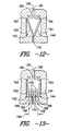
- the convolution seal 140 includes two outer legs 152 and 154 connected to each other at intersection 172, with no inner legs therebetween. Each entire outer leg 152, 154 is linear. The first outer leg 152 and second outer leg 154 have an outward bias in an operating condition.
- FIG. 13 illustrates a convolution seal 140 according to another embodiment of the present disclosure.
- the convolution seal 140 includes four inner legs 156, 158 between outer legs 152, 154. Each entire outer leg 152, 154 is linear. The first outer leg 152 and second outer leg 154 have an outward bias in an operating condition.
- FIGS. 5 , 6 and 14 illustrate a convolution seal 140 according to one embodiment of the present disclosure.
- the convolution seal 140 includes eight inner legs 156, 158 between outer legs 152, 154. A portion of each outer leg 152, 154 is curvilinear, while the surrounding portions that include ends 162, 164 and intersection 166, 168 are linear.
- the first outer leg 152 and second outer leg 154 have an outward bias in an operating condition.
- a convolution seal 140 of the present disclosure may advantageously allow adjacent transition ducts 50, such as the outlets 54 thereof, to move about or along one or more of the various axis 90, 92, 94 while maintaining a seal therebetween. This may advantageously accommodate the thermal growth of the transition ducts 50, which may be offset as discussed above, while allowing the transition duct 50 to remain sufficiently sealed together. This is particularly advantageous due to the unique formation of airfoil surfaces between adjacent transition ducts 50.
- the convolution seal 140 may allow movement of a transition duct 50, such as of the outlet 54 of the transition duct 50, about or along one, two, or three of the longitudinal axis 90, the tangential axis 92 and the radial axis 94.
- the convolution seal 140 allows movement about or along all three axes.
- convolution seals 140 advantageously provide a seal that accommodates the unexpected movement of the transition ducts 50 of the present disclosure.
Landscapes
- Engineering & Computer Science (AREA)
- Mechanical Engineering (AREA)
- General Engineering & Computer Science (AREA)
- Chemical & Material Sciences (AREA)
- Combustion & Propulsion (AREA)
- Turbine Rotor Nozzle Sealing (AREA)
Abstract
Description
- The subject matter disclosed herein relates generally to turbine systems, and more particularly to seals between adjacent transition ducts of turbine systems.
- Turbine systems are widely utilized in fields such as power generation. For example, a conventional gas turbine system includes a compressor section, a combustor section, and at least one turbine section. The compressor section is configured to compress air as the air flows through the compressor section. The air is then flowed from the compressor section to the combustor section, where it is mixed with fuel and combusted, generating a hot gas flow. The hot gas flow is provided to the turbine section, which utilizes the hot gas flow by extracting energy from it to power the compressor, an electrical generator, and other various loads.
- The combustor sections of turbine systems generally include tubes or ducts for flowing the combusted hot gas therethrough to the turbine section or sections. Recently, combustor sections have been introduced which include tubes or ducts that shift the flow of the hot gas. For example, ducts for combustor sections have been introduced that, while flowing the hot gas longitudinally therethrough, additionally shift the flow radially or tangentially such that the flow has various angular components. These designs have various advantages, including eliminating first stage nozzles from the turbine sections. The first stage nozzles were previously provided to shift the hot gas flow, and may not be required due to the design of these ducts. The elimination of first stage nozzles may eliminate associated pressure drops and increase the efficiency and power output of the turbine system.
- However, the connection of these ducts to each other is of increased concern. For example, because the ducts do not simply extend along a longitudinal axis, but are rather shifted off-axis from the inlet of the duct to the outlet of the duct, thermal expansion of the ducts can cause undesirable shifts in the ducts along or about various axes. Such shifts can cause unexpected gaps between the adjacent ducts, thus undesirably allowing leakage and mixing of cooling air and hot gas.
- This problem is of particular concern due to the interaction between the adjacent ducts. For example, in many embodiments an airfoil trailing edge is formed by adjacent ducts. This airfoil may shift the hot gas flow in the ducts, and thus eliminate the need for first stage nozzles. However, because the airfoil is formed by the adjacent ducts, any gaps between the ducts can allow leakage and mixing which can interfere with the performance of the airfoil.
- Accordingly, an improved seal between adjacent combustor ducts in a turbine system would be desired in the art. For example, a seal that allows for thermal growth of the adjacent ducts while preventing gaps between the adjacent ducts would be advantageous.
- Aspects and advantages of the invention will be set forth in part in the following description, or may be obvious from the description, or may be learned through practice of the invention.
- In one aspect, the invention resides in a turbine system. The turbine system includes a transition duct. The transition duct includes an inlet, an outlet, and a passage extending between the inlet and the outlet and defining a longitudinal axis, a radial axis, and a tangential axis. The outlet of the transition duct is offset from the inlet along the longitudinal axis and the tangential axis. The transition duct further includes an interface feature for interfacing with an adjacent transition duct. The turbine system further includes a convolution seal contacting the interface feature to provide a seal between the interface feature and the adjacent transition duct.
- In another aspect, a turbine system is disclosed. The turbine system include a plurality of transition ducts disposed in a generally annular array. Each of the plurality of transition ducts includes an inlet, an outlet, and a passage extending between the inlet and the outlet and defining a longitudinal axis, a radial axis, and a tangential axis. The outlet of the transition duct is offset from the inlet along the longitudinal axis and the tangential axis. Each of the plurality of transition ducts further includes a first interface feature and a second interface feature. The turbine system further includes a plurality of convolution seals. Each of the plurality of convolution seals contacts and provides a seal between a first interface feature of one of the plurality of transition ducts and a second interface feature of an adjacent one of the plurality of transition ducts.
- These and other features, aspects and advantages of the present invention will become better understood with reference to the following description and appended claims. The accompanying drawings, which are incorporated in and constitute a part of this specification, illustrate embodiments of the invention and, together with the description, serve to explain the principles of the invention.
- Embodiments of the present invention will now be described, by way of example only, with reference to the accompanying drawings, in which:
-
FIG. 1 is a schematic view of a gas turbine system according to one embodiment of the present disclosure; -
FIG. 2 is a cross-sectional view of several portions of a gas turbine system according to one embodiment of the present disclosure; -
FIG. 3 is a perspective view of an annular array of transition ducts according to one embodiment of the present disclosure; -
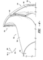
FIG. 4 is a top perspective view of a plurality of transition ducts according to one embodiment of the present disclosure; -
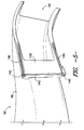
FIG. 5 is a side perspective view of a transition duct according to one embodiment of the present disclosure; -
FIG. 6 is a cutaway perspective view of a plurality of transition ducts according to one embodiment of the present disclosure; -
FIG. 7 is a cross-sectional view of a turbine section of a gas turbine system according to one embodiment of the present disclosure; and -
FIG. 8 is a cross-sectional view of an interface between a transition duct and an adjacent transition duct according to one embodiment of the present disclosure; -
FIG. 9 is a cross-sectional view of an interface between a transition duct and an adjacent transition duct according to another embodiment of the present disclosure; -
FIG. 10 is a cross-sectional view of an interface between a transition duct and an adjacent transition duct according to another embodiment of the present disclosure; -
FIG. 11 is a cross-sectional view of an interface between a transition duct and an adjacent transition duct according to another embodiment of the present disclosure; -
FIG. 12 is a cross-sectional view of an interface between a transition duct and an adjacent transition duct according to another embodiment of the present disclosure; -
FIG. 13 is a cross-sectional view of an interface between a transition duct and an adjacent transition duct according to another embodiment of the present disclosure; and -
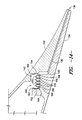
FIG. 14 is a cross-sectional view, along the lines 14-14 ofFIG. 6 , of an interface between a transition duct and an adjacent transition duct according to another embodiment of the present disclosure. - Reference now will be made in detail to embodiments of the invention, one or more examples of which are illustrated in the drawings. Each example is provided by way of explanation of the invention, not limitation of the invention. In fact, it will be apparent to those skilled in the art that various modifications and variations can be made in the present invention without departing from the scope or spirit of the invention. For instance, features illustrated or described as part of one embodiment can be used with another embodiment to yield a still further embodiment. Thus, it is intended that the present invention covers such modifications and variations as come within the scope of the appended claims and their equivalents.
-
FIG. 1 is a schematic diagram of agas turbine system 10. It should be understood that theturbine system 10 of the present disclosure need not be agas turbine system 10, but rather may be anysuitable turbine system 10, such as a steam turbine system or other suitable system. Thegas turbine system 10 may include acompressor section 12, acombustor section 14 which may include a plurality ofcombustors 15 as discussed below, and aturbine section 16. Thecompressor section 12 andturbine section 16 may be coupled by ashaft 18. Theshaft 18 may be a single shaft or a plurality of shaft segments coupled together to formshaft 18. Theshaft 18 may further be coupled to a generator or other suitable energy storage device, or may be connected directly to, for example, an electrical grid. Exhaust gases from thesystem 10 may be exhausted into the atmosphere, flowed to a steam turbine or other suitable system, or recycled through a heat recovery steam generator. - Referring to
FIG. 2 , a simplified drawing of several portions of agas turbine system 10 is illustrated. Thegas turbine system 10 as shown inFIG. 2 comprises acompressor section 12 for pressurizing a working fluid, discussed below, that is flowing through thesystem 10. Pressurized working fluid discharged from thecompressor section 12 flows into acombustor section 14, which may include a plurality of combustors 15 (only one of which is illustrated inFIG. 2 ) disposed in an annular array about an axis of thesystem 10. The working fluid entering thecombustor section 14 is mixed with fuel, such as natural gas or another suitable liquid or gas, and combusted. Hot gases of combustion flow from each combustor 15 to aturbine section 16 to drive thesystem 10 and generate power. - A
combustor 15 in thegas turbine 10 may include a variety of components for mixing and combusting the working fluid and fuel. For example, thecombustor 15 may include acasing 21, such as acompressor discharge casing 21. A variety of sleeves, which may be axially extending annular sleeves, may be at least partially disposed in thecasing 21. The sleeves, as shown inFIG. 2 , extend axially along a generallylongitudinal axis 98, such that the inlet of a sleeve is axially aligned with the outlet. For example, acombustor liner 22 may generally define acombustion zone 24 therein. Combustion of the working fluid, fuel, and optional oxidizer may generally occur in thecombustion zone 24. The resulting hot gases of combustion may flow generally axially along thelongitudinal axis 98 downstream through thecombustion liner 22 into atransition piece 26, and then flow generally axially along thelongitudinal axis 98 through thetransition piece 26 and into theturbine section 16. - The
combustor 15 may further include afuel nozzle 40 or a plurality offuel nozzles 40. Fuel may be supplied to thefuel nozzles 40 by one or more manifolds (not shown). As discussed below, thefuel nozzle 40 orfuel nozzles 40 may supply the fuel and, optionally, working fluid to thecombustion zone 24 for combustion. - As shown in
FIGS. 3 through 6 , acombustor 15 according to the present disclosure may include one ormore transition ducts 50. Thetransition ducts 50 of the present disclosure may be provided in place of various axially extending sleeves of other combustors. For example, atransition duct 50 may replace the axially extendingtransition piece 26 and, optionally, thecombustor liner 22 of acombustor 15. Thus, the transition duct may extend from thefuel nozzles 40, or from thecombustor liner 22. As discussed below, thetransition duct 50 may provide various advantages over the axially extendingcombustor liners 22 andtransition pieces 26 for flowing working fluid therethrough and to theturbine section 16. - As shown, the plurality of
transition ducts 50 may be disposed in an annular array about alongitudinal axis 90. Further, eachtransition duct 50 may extend between afuel nozzle 40 or plurality offuel nozzles 40 and theturbine section 16. For example, eachtransition duct 50 may extend from thefuel nozzles 40 to theturbine section 16. Thus, working fluid may flow generally from thefuel nozzles 40 through thetransition duct 50 to theturbine section 16. In some embodiments, thetransition ducts 50 may advantageously allow for the elimination of the first stage nozzles in the turbine section, which may eliminate any associated drag and pressure drop and increase the efficiency and output of thesystem 10. - Each
transition duct 50 may have aninlet 52, anoutlet 54, and apassage 56 therebetween. Theinlet 52 andoutlet 54 of atransition duct 50 may have generally circular or oval cross-sections, rectangular cross-sections, triangular cross-sections, or any other suitable polygonal cross-sections. Further, it should be understood that theinlet 52 andoutlet 54 of atransition duct 50 need not have similarly shaped cross-sections. For example, in one embodiment, theinlet 52 may have a generally circular cross-section, while theoutlet 54 may have a generally rectangular cross-section. - Further, the
passage 56 may be generally tapered between theinlet 52 and theoutlet 54. For example, in an exemplary embodiment, at least a portion of thepassage 56 may be generally conically shaped. Additionally or alternatively, however, thepassage 56 or any portion thereof may have a generally rectangular cross-section, triangular cross-section, or any other suitable polygonal cross-section. It should be understood that the cross-sectional shape of thepassage 56 may change throughout thepassage 56 or any portion thereof as thepassage 56 tapers from the relativelylarger inlet 52 to the relativelysmaller outlet 54. - The
outlet 54 of each of the plurality oftransition ducts 50 may be offset from theinlet 52 of therespective transition duct 50. The term "offset", as used herein, means spaced from along the identified coordinate direction. Theoutlet 54 of each of the plurality oftransition ducts 50 may be longitudinally offset from theinlet 52 of therespective transition duct 50, such as offset along thelongitudinal axis 90. - Additionally, in exemplary embodiments, the
outlet 54 of each of the plurality oftransition ducts 50 may be tangentially offset from theinlet 52 of therespective transition duct 50, such as offset along atangential axis 92. Because theoutlet 54 of each of the plurality oftransition ducts 50 is tangentially offset from theinlet 52 of therespective transition duct 50, thetransition ducts 50 may advantageously utilize the tangential component of the flow of working fluid through thetransition ducts 50 to eliminate the need for first stage nozzles in theturbine section 16, as discussed below. - Further, in exemplary embodiments, the
outlet 54 of each of the plurality oftransition ducts 50 may be radially offset from theinlet 52 of therespective transition duct 50, such as offset along aradial axis 94. Because theoutlet 54 of each of the plurality oftransition ducts 50 is radially offset from theinlet 52 of therespective transition duct 50, thetransition ducts 50 may advantageously utilize the radial component of the flow of working fluid through thetransition ducts 50 to further eliminate the need for first stage nozzles in theturbine section 16, as discussed below. - It should be understood that the
tangential axis 92 and theradial axis 94 are defined individually for eachtransition duct 50 with respect to the circumference defined by the annular array oftransition ducts 50, as shown inFIG. 3 , and that theaxes transition duct 50 about the circumference based on the number oftransition ducts 50 disposed in an annular array about thelongitudinal axis 90. - As discussed, after hot gases of combustion are flowed through the
transition duct 50, they may be flowed from thetransition duct 50 into theturbine section 16. As shown inFIG. 7 , aturbine section 16 according to the present disclosure may include ashroud 102, which may define ahot gas path 104. Theshroud 102 may be formed from a plurality of shroud blocks 106. The shroud blocks 106 may be disposed in one or more annular arrays, each of which may define a portion of thehot gas path 104 therein. - The
turbine section 16 may further include a plurality ofbuckets 112 and a plurality ofnozzles 114. Each of the plurality ofbuckets 112 andnozzles 114 may be at least partially disposed in thehot gas path 104. Further, the plurality ofbuckets 112 and the plurality ofnozzles 114 may be disposed in one or more annular arrays, each of which may define a portion of thehot gas path 104. - The
turbine section 16 may include a plurality of turbine stages. Each stage may include a plurality ofbuckets 112 disposed in an annular array and a plurality ofnozzles 114 disposed in an annular array. For example, in one embodiment, theturbine section 16 may have three stages, as shown inFIG. 7 . For example, a first stage of theturbine section 16 may include a first stage nozzle assembly (not shown) and a firststage buckets assembly 122. The nozzles assembly may include a plurality ofnozzles 114 disposed and fixed circumferentially about theshaft 18. Thebucket assembly 122 may include a plurality ofbuckets 112 disposed circumferentially about theshaft 18 and coupled to theshaft 18. In exemplary embodiments wherein the turbine section is coupled tocombustor section 14 comprising a plurality oftransition ducts 50, however, the first stage nozzle assembly may be eliminated, such that no nozzles are disposed upstream of the firststage bucket assembly 122. Upstream may be defined relative to the flow of hot gases of combustion through thehot gas path 104. - A second stage of the
turbine section 16 may include a secondstage nozzle assembly 123 and a secondstage buckets assembly 124. Thenozzles 114 included in thenozzle assembly 123 may be disposed and fixed circumferentially about theshaft 18. Thebuckets 112 included in thebucket assembly 124 may be disposed circumferentially about theshaft 18 and coupled to theshaft 18. The secondstage nozzle assembly 123 is thus positioned between the firststage bucket assembly 122 and secondstage bucket assembly 124 along thehot gas path 104. A third stage of theturbine section 16 may include a thirdstage nozzle assembly 125 and a thirdstage bucket assembly 126. Thenozzles 114 included in thenozzle assembly 125 may be disposed and fixed circumferentially about theshaft 18. Thebuckets 112 included in thebucket assembly 126 may be disposed circumferentially about theshaft 18 and coupled to theshaft 18. The thirdstage nozzle assembly 125 is thus positioned between the secondstage bucket assembly 124 and thirdstage bucket assembly 126 along thehot gas path 104. - It should be understood that the
turbine section 16 is not limited to three stages, but rather that any number of stages are within the scope and spirit of the present disclosure. - Each
transition duct 50 may interface with one or moreadjacent transition ducts 50. For example, atransition duct 50 may include one or more contact faces 130, which may be included in the outlet of thetransition duct 50. The contact faces 130 may contact associated contact faces 130 ofadjacent transition ducts 50, as shown, to provide an interface between thetransition ducts 50. - Further, the
adjacent transition ducts 50 may combine to form various surface of an airfoil. These various surfaces may shift the hot gas flow in thetransition ducts 50, and thus eliminate the need for first stage nozzles, as discussed above. For example, as shown inFIG. 6 , an inner surface of apassage 56 of atransition duct 50 may define apressure side 132, while an opposing inner surface of apassage 56 of anadjacent transition duct 50 may define asuction side 134. When theadjacent transition ducts 50, such as the contact faces 130 thereof, interface with each other, thepressure side 132 andsuction side 134 may combine to define a trailingedge 136. - As discussed above, the
outlet 54 of each of the plurality oftransition ducts 50 may be longitudinally, radially, and/or tangentially offset from theinlet 52 of therespective transition duct 50. These various offsets of thetransition ducts 50 may cause unexpected movement of thetransition ducts 50 due to thermal growth during operation of thesystem 10. For example, eachtransition duct 50 may interface with one or moreadjacent transition ducts 50. However, thermal growth may cause theoutlet 54 to move with respect to theturbine section 16 about or along one or more of thelongitudinal axis 90,tangential axis 92, and/orradial axis 94. - To prevent gaps between
adjacent transition ducts 50, the present disclosure may further be directed to one or more convolution seals 140. Eachconvolution seal 140 may be provided at an interface betweenadjacent transition ducts 50. The present inventors have discovered that convolution seals are particularly advantageous at sealing the interface betweenadjacent transition ducts 50, because the convolution seals 140 can accommodate the unexpected movement of theoutlet 54 along or about thevarious axis - As shown in
FIGS. 4 through 6 and8 through 14 , atransition duct 50 according to the present disclosure includes one or more first interface features 142. The interface features 142 may be included on one or more contact faces 130 of thetransition duct 50, and are positioned to interface with adjacent contact faces 130 and interface features, such as second interface features 144, thereof ofadjacent transition ducts 50. In one embodiment as shown, for example, two interface features 142 may be included on acontact face 130 extending generally parallel to each other, while athird interface feature 142 may be included on thecontact face 130 that extends generally perpendicular to and between the two parallel interface features 142. The associatedcontact face 130 of anadjacent transition duct 50 may include associated second interface features 144. It should be understood, however, that the present disclosure is not limited to interface features position as shown and described above, and rather that any suitable interface features having any suitable positioning on acontact face 130 is within the scope and spirit of the present disclosure. - In some exemplary embodiments, as shown in
FIGS. 3 through 6 and8 through 13 , an interface feature, such as afirst interface feature 142 and/or asecond interface feature 144, is a channel. The channel may be defined in acontact face 130. Aconvolution seal 140 may, as shown, be at least partially disposed in the channel. The channel may retain the convolution seal during operation of thesystem 10. In other exemplary embodiments, as shown inFIG. 14 , an interface feature, such as afirst interface feature 142 and/or asecond interface feature 144, is a lip. The lip may be defined in acontact face 130. Aconvolution seal 140 may, as shown, be at least partially disposed in the lip. The lip may retain the convolution seal during operation of thesystem 10. In still other embodiments, an interface feature, such as afirst interface feature 142 and/or asecond interface feature 144, may be a portion of acontact face 130, or any other suitable feature interact with aconvolution seal 140 to provide a seal as discussed herein. - As shown, a
convolution seal 140 according to the present disclosure may contact afirst interface feature 142 of acontact face 130 of atransition duct 50 and an associatedsecond interface feature 144 of acontact face 130 of anadjacent transition duct 50, such as by being disposed at least partially within thefirst interface feature 142 and associatedsecond interface feature 144. Such contact may allow the first andsecond features adjacent transition ducts 50. - A
convolution seal 140 according to the present disclosure has one or more folds or curves, as shown, thus defining various legs that facilitate sealing. Theseal 140 may be formed from a metal or metal alloy, or from any other suitable material. The convolutions in theseal 140, as discussed below, may allow the various legs of the seal to flex relative to one another to facilitate sealing. As shown inFIGS. 4 through 6 and8 through 14 , aconvolution seal 140 according to the present disclosure may includeouter legs convolution seal 140 may further includeinner legs outer legs outer legs FIGS. 4 through 6 and8 through 11 ,outer leg 152 may be connected toinner leg 156 atintersection 166, andouter leg 164 may be connected toinner leg 158 atintersection 168.Inner legs intersection 170. Theouter legs inner legs FIG. 12 , theouter legs intersection 172, with no inner legs therebetween, and may thus form a generally V-shaped cross-section, as shown. In still other embodiments, as shown inFIGS. 13 and14 ,outer leg 152 may be connected toinner leg 156 atintersection 166, andouter leg 164 may be connected toinner leg 158 atintersection 168. Additionalinner legs inner legs outer legs inner legs intersections 170. The various intersections are convolutions, as shown. It should be understood that zero, one, two, three, four, five, six, seven, eight or more inner legs may be provided between the outer legs of a convolution seal and have any suitable arrangement according to the present disclosure. - As mentioned above, a
convolution seal 140 according to the present disclosure may contact afirst interface feature 142, and may further contact asecond interface feature 144, to provide a seal between adjacent contact faces 130 and thus betweenadjacent transition ducts 50. In exemplary embodiments, oneouter leg 152 may contact one of thefirst interface feature 142 orsecond interface feature 144, such as by being disposed therein, and the otherouter leg 154 may contact the other of thefirst interface feature 142 orsecond interface feature 144, such as by being disposed therein. Theinner legs outer legs outer legs convolution seal 140 may thus advantageously provide a seal between the contact faces 130. - One or more of the
outer legs inner legs leg FIG. 8 , a portion of anouter leg end intersection outer leg end intersection outer leg FIG. 9 and14 , an entireouter leg FIGS. 10 through 13 , an entireouter leg - As further shown in
FIGS. 8 through 14 , theouter legs FIGS. 10 and14 , thelegs seal 140 is subjected to the temperature or temperature range and pressure or pressure range that it may be subjected to during normal operation of thesystem 10. For example, in one embodiment, the operating condition may be the condition that theseal 140 is being subjected to inside of thesystem 10 during operation thereof. In these embodiments, and in further embodiments as shown inFIGS. 10 and14 , awidth 182 between thelegs ends width 184 between the legs at theintersections FIGS. 8 through 9 and11 through 13 , the firstouter leg 152 and/or the secondouter leg 154 may have an outward bias in an operating condition. In these embodiments, awidth 182 between thelegs ends width 184 between the legs at theintersections width 184 may be zero), as shown. In still other embodiments, the firstouter leg 152 and/or the secondouter leg 154 may have an inward bias in an operating condition. In these embodiments, awidth 182 between thelegs ends width 184 between the legs at theintersections -
FIG. 8 thus illustrates aconvolution seal 140 according to one embodiment of the present disclosure. In this embodiment, theconvolution seal 140 includes twoinner legs outer legs outer leg intersection outer leg 152 and secondouter leg 154 have an outward bias in an operating condition. -
FIGS. 4 and9 illustrate aconvolution seal 140 according to another embodiment of the present disclosure. In this embodiment, theconvolution seal 140 includes twoinner legs outer legs outer leg outer leg 152 and secondouter leg 154 have an outward bias in an operating condition. -
FIG. 10 illustrates aconvolution seal 140 according to another embodiment of the present disclosure. In this embodiment, theconvolution seal 140 includes twoinner legs outer legs outer leg outer leg 152 and secondouter leg 154 are generally parallel in an operating condition. -
FIG. 11 illustrates aconvolution seal 140 according to another embodiment of the present disclosure. In this embodiment, theconvolution seal 140 includes twoinner legs outer legs outer leg outer leg 152 and secondouter leg 154 have an outward bias in an operating condition. -
FIG. 12 illustrates aconvolution seal 140 according to another embodiment of the present disclosure. In this embodiment, theconvolution seal 140 includes twoouter legs intersection 172, with no inner legs therebetween. Each entireouter leg outer leg 152 and secondouter leg 154 have an outward bias in an operating condition. -
FIG. 13 illustrates aconvolution seal 140 according to another embodiment of the present disclosure. In this embodiment, theconvolution seal 140 includes fourinner legs outer legs outer leg outer leg 152 and secondouter leg 154 have an outward bias in an operating condition. -
FIGS. 5 ,6 and14 illustrate aconvolution seal 140 according to one embodiment of the present disclosure. In this embodiment, theconvolution seal 140 includes eightinner legs outer legs outer leg intersection outer leg 152 and secondouter leg 154 have an outward bias in an operating condition. - A
convolution seal 140 of the present disclosure may advantageously allowadjacent transition ducts 50, such as theoutlets 54 thereof, to move about or along one or more of thevarious axis transition ducts 50, which may be offset as discussed above, while allowing thetransition duct 50 to remain sufficiently sealed together. This is particularly advantageous due to the unique formation of airfoil surfaces betweenadjacent transition ducts 50. In exemplary embodiments, for example, theconvolution seal 140 may allow movement of atransition duct 50, such as of theoutlet 54 of thetransition duct 50, about or along one, two, or three of thelongitudinal axis 90, thetangential axis 92 and theradial axis 94. In exemplary embodiments, theconvolution seal 140 allows movement about or along all three axes. Thus, convolution seals 140 advantageously provide a seal that accommodates the unexpected movement of thetransition ducts 50 of the present disclosure. - This written description uses examples to disclose the invention, including the best mode, and also to enable any person skilled in the art to practice the invention, including making and using any devices or systems and performing any incorporated methods. The patentable scope of the invention is defined by the claims, and may include other examples that occur to those skilled in the art. Such other examples are intended to be within the scope of the claims if they include structural elements that do not differ from the literal language of the claims, or if they include equivalent structural elements with insubstantial differences from the literal languages of the claims.
Claims (13)
- A turbine system (10), comprising:a transition duct (50) comprising an inlet (52), an outlet (54), and a passage (56) extending between the inlet (52) and the outlet (54) and defining a longitudinal axis (90), a radial axis (94), and a tangential axis (92), the outlet (54) of the transition duct (50) offset from the inlet (52) along the longitudinal axis (90) and the tangential axis (92), the transition duct (50) further comprising an interface feature (142) for interfacing with an adjacent transition duct (50); anda convolution seal (140) contacting the interface feature (142) to provide a seal between the interface feature (142) and the adjacent transition duct (50).
- The turbine system of claim 1, wherein the convolution seal (140) includes a first outer leg (152) and a second outer leg (154), and wherein at least a portion of one of the first outer leg (152) and the second outer leg (154) is curvilinear.
- The turbine system of claim 1, wherein the convolution seal (140) includes a first outer leg (152) and a second outer leg (154), and wherein at least a portion of one of the first outer leg (152) and the second outer leg (154) is linear.
- The turbine system of any of claims 1 to 3, wherein the convolution seal (140) includes a first outer leg (152) and a second outer leg (154), and wherein the first outer leg (152) and second outer leg (154) are generally parallel when in an operating condition.
- The turbine system of any of claims 1 to 3, wherein the convolution seal (140) includes a first outer leg (152) and a second outer leg (154), and wherein the first outer leg (152) and second outer leg (154) have an outward bias in an operating condition.
- The turbine system of any preceding claim, wherein the interface feature (142) is a channel, and wherein the convolution seal (140) is at least partially disposed in the channel.
- The turbine system of any preceding claim, further comprising a plurality of convolution seals (140).
- The turbine system of any preceding claim, further comprising a plurality of interface features (142).
- The turbine system of any preceding claim, wherein the outlet (54) of the transition duct (50) is further offset from the inlet (52) along the radial axis (94).
- The turbine system of any preceding claim, wherein the interface feature (142) is a first interface feature (142), and wherein the adjacent transition duct (50) comprises a second interface feature (144) for interfacing with the first interface feature, the convolution seal (140) contacting the second interface feature (144) to provide a seal between the first and second interface features (142, 144).
- The turbine system of any preceding claim, further comprising a turbine section (16) in communication with the transition duct (50) and the adjacent transition duct (50), the turbine section (16) comprising a first stage bucket assembly (122).
- The turbine system of claim 11, wherein no nozzles (40) are disposed upstream of the first stage bucket assembly (122).
- The turbine system of any preceding claim comprising:a plurality of transition ducts disposed in a generally annular array; anda plurality of convolution seals (140), each of the plurality of convolution seals (140) contacting and providing a seal between a first interface feature (142) of one of the plurality of transition ducts (50) and a second interface feature (144) of an adjacent one of the plurality of transition ducts (50).
Applications Claiming Priority (1)
| Application Number | Priority Date | Filing Date | Title |
|---|---|---|---|
| US13/459,533 US9038394B2 (en) | 2012-04-30 | 2012-04-30 | Convolution seal for transition duct in turbine system |
Publications (2)
| Publication Number | Publication Date |
|---|---|
| EP2660427A1 true EP2660427A1 (en) | 2013-11-06 |
| EP2660427B1 EP2660427B1 (en) | 2017-02-22 |
Family
ID=47826934
Family Applications (1)
| Application Number | Title | Priority Date | Filing Date |
|---|---|---|---|
| EP13156920.4A Not-in-force EP2660427B1 (en) | 2012-04-30 | 2013-02-27 | Turbine system comprising a transition duct with a convolution seal |
Country Status (5)
| Country | Link |
|---|---|
| US (1) | US9038394B2 (en) |
| EP (1) | EP2660427B1 (en) |
| JP (1) | JP6186133B2 (en) |
| CN (1) | CN103375261B (en) |
| RU (1) | RU2013108685A (en) |
Cited By (5)
| Publication number | Priority date | Publication date | Assignee | Title |
|---|---|---|---|---|
| EP2886803A1 (en) * | 2013-12-17 | 2015-06-24 | Rolls-Royce Corporation | Seal for gas turbine engines |
| WO2015199694A1 (en) * | 2014-06-26 | 2015-12-30 | Siemens Energy, Inc. | Converging flow joint insert system at an intersection between adjacent transitions duct bodies |
| WO2015199693A1 (en) * | 2014-06-26 | 2015-12-30 | Siemens Energy, Inc. | Converging flow joint insert system at an intersection between adjacent transition duct bodljs |
| EP3222820A1 (en) * | 2016-03-24 | 2017-09-27 | General Electric Company | Transition duct assembly |
| EP2584144A3 (en) * | 2011-10-18 | 2018-03-07 | General Electric Company | Transition nozzle |
Families Citing this family (8)
| Publication number | Priority date | Publication date | Assignee | Title |
|---|---|---|---|---|
| US20130283817A1 (en) * | 2012-04-30 | 2013-10-31 | General Electric Company | Flexible seal for transition duct in turbine system |
| WO2015076889A1 (en) * | 2013-09-13 | 2015-05-28 | United Technologies Corporation | System and apparatus for seal retention and protection |
| US20170145839A1 (en) * | 2014-06-17 | 2017-05-25 | Siemens Energy, Inc. | Transition duct system with a robust converging flow joint at an intersection between adjacent transitions extending between a combustor and a turbine assembly in a gas turbine engine |
| US20160033134A1 (en) * | 2014-08-01 | 2016-02-04 | General Electric Company | Seal in combustor nozzle of gas turbine engine |
| JP6474485B2 (en) * | 2014-10-07 | 2019-02-27 | シーメンス エナジー インコーポレイテッド | Equipment for gas turbine combustion engines |
| DE102015202570A1 (en) * | 2015-02-12 | 2016-08-18 | Rolls-Royce Deutschland Ltd & Co Kg | Sealing of a marginal gap between effusion shingles of a gas turbine combustor |
| US11473437B2 (en) * | 2015-09-24 | 2022-10-18 | General Electric Company | Turbine snap in spring seal |
| US9810434B2 (en) * | 2016-01-21 | 2017-11-07 | Siemens Energy, Inc. | Transition duct system with arcuate ceramic liner for delivering hot-temperature gases in a combustion turbine engine |
Citations (2)
| Publication number | Priority date | Publication date | Assignee | Title |
|---|---|---|---|---|
| US7090224B2 (en) * | 2003-09-02 | 2006-08-15 | Eagle Engineering Aerospace Co., Ltd. | Seal device |
| EP1903184A2 (en) * | 2006-09-21 | 2008-03-26 | Siemens Power Generation, Inc. | Combustion transition duct providing stage 1 tangential turning for turbine engines |
Family Cites Families (64)
| Publication number | Priority date | Publication date | Assignee | Title |
|---|---|---|---|---|
| US4121843A (en) * | 1977-10-04 | 1978-10-24 | Pressure Science, Incorporated | Multiple convolution sealing ring |
| US4422288A (en) | 1981-03-02 | 1983-12-27 | General Electric Company | Aft mounting system for combustion transition duct members |
| US4465284A (en) | 1983-09-19 | 1984-08-14 | General Electric Company | Scalloped cooling of gas turbine transition piece frame |
| GB2190154B (en) | 1986-05-02 | 1990-01-10 | Heat Transfer Technology | Metallic sealing ring |
| US5240263A (en) | 1988-06-01 | 1993-08-31 | Specialist Sealing Limited | Metallic sealing rings and their manufacture |
| US5118120A (en) | 1989-07-10 | 1992-06-02 | General Electric Company | Leaf seals |
| US5077967A (en) | 1990-11-09 | 1992-01-07 | General Electric Company | Profile matched diffuser |
| US5149250A (en) | 1991-02-28 | 1992-09-22 | General Electric Company | Gas turbine vane assembly seal and support system |
| US5249920A (en) | 1992-07-09 | 1993-10-05 | General Electric Company | Turbine nozzle seal arrangement |
| FR2711771B1 (en) | 1993-10-27 | 1995-12-01 | Snecma | Variable circumferential feed chamber diffuser. |
| US5414999A (en) | 1993-11-05 | 1995-05-16 | General Electric Company | Integral aft frame mount for a gas turbine combustor transition piece |
| US5457954A (en) | 1993-12-21 | 1995-10-17 | Solar Turbines Inc | Rolling contact mounting arrangement for a ceramic combustor |
| EP0718468B1 (en) | 1994-12-20 | 2001-10-31 | General Electric Company | Transition piece frame support |
| DE19549143A1 (en) | 1995-12-29 | 1997-07-03 | Abb Research Ltd | Gas turbine ring combustor |
| US6076835A (en) | 1997-05-21 | 2000-06-20 | Allison Advanced Development Company | Interstage van seal apparatus |
| US5934687A (en) | 1997-07-07 | 1999-08-10 | General Electric Company | Gas-path leakage seal for a turbine |
| DE59808754D1 (en) | 1997-12-19 | 2003-07-24 | Mtu Aero Engines Gmbh | Premix combustion chamber for a gas turbine |
| GB2335470B (en) | 1998-03-18 | 2002-02-13 | Rolls Royce Plc | A seal |
| US6237921B1 (en) * | 1998-09-02 | 2001-05-29 | General Electric Company | Nested bridge seal |
| US6199871B1 (en) * | 1998-09-02 | 2001-03-13 | General Electric Company | High excursion ring seal |
| JP4301692B2 (en) * | 2000-03-31 | 2009-07-22 | 三菱重工業株式会社 | gas turbine |
| US6471475B1 (en) | 2000-07-14 | 2002-10-29 | Pratt & Whitney Canada Corp. | Integrated duct diffuser |
| US6431825B1 (en) | 2000-07-28 | 2002-08-13 | Alstom (Switzerland) Ltd | Seal between static turbine parts |
| US6442946B1 (en) | 2000-11-14 | 2002-09-03 | Power Systems Mfg., Llc | Three degrees of freedom aft mounting system for gas turbine transition duct |
| US6450762B1 (en) | 2001-01-31 | 2002-09-17 | General Electric Company | Integral aft seal for turbine applications |
| US6431555B1 (en) | 2001-03-14 | 2002-08-13 | General Electric Company | Leaf seal for inner and outer casings of a turbine |
| US6564555B2 (en) | 2001-05-24 | 2003-05-20 | Allison Advanced Development Company | Apparatus for forming a combustion mixture in a gas turbine engine |
| US6537023B1 (en) | 2001-12-28 | 2003-03-25 | General Electric Company | Supplemental seal for the chordal hinge seal in a gas turbine |
| JP3951928B2 (en) | 2002-02-21 | 2007-08-01 | 株式会社日立製作所 | High temperature components for gas turbines |
| US6652229B2 (en) | 2002-02-27 | 2003-11-25 | General Electric Company | Leaf seal support for inner band of a turbine nozzle in a gas turbine engine |
| GB2390890B (en) | 2002-07-17 | 2005-07-06 | Rolls Royce Plc | Diffuser for gas turbine engine |
| US6662567B1 (en) | 2002-08-14 | 2003-12-16 | Power Systems Mfg, Llc | Transition duct mounting system |
| US6834507B2 (en) | 2002-08-15 | 2004-12-28 | Power Systems Mfg., Llc | Convoluted seal with enhanced wear capability |
| US7007480B2 (en) | 2003-04-09 | 2006-03-07 | Honeywell International, Inc. | Multi-axial pivoting combustor liner in gas turbine engine |
| US7024863B2 (en) | 2003-07-08 | 2006-04-11 | Pratt & Whitney Canada Corp. | Combustor attachment with rotational joint |
| JP4727934B2 (en) * | 2004-02-20 | 2011-07-20 | イーグル・エンジニアリング・エアロスペース株式会社 | Sealing device |
| US7721547B2 (en) * | 2005-06-27 | 2010-05-25 | Siemens Energy, Inc. | Combustion transition duct providing stage 1 tangential turning for turbine engines |
| US7788932B2 (en) * | 2005-08-23 | 2010-09-07 | Mitsubishi Heavy Industries, Ltd. | Seal structure for gas turbine combustor |
| US7637110B2 (en) | 2005-11-30 | 2009-12-29 | General Electric Company | Methods and apparatuses for assembling a gas turbine engine |
| JP4690905B2 (en) * | 2006-02-17 | 2011-06-01 | 三菱重工業株式会社 | SEALING DEVICE AND GAS TURBINE HAVING THE SAME |
| US7784264B2 (en) | 2006-08-03 | 2010-08-31 | Siemens Energy, Inc. | Slidable spring-loaded transition-to-turbine seal apparatus and heat-shielding system, comprising the seal, at transition/turbine junction of a gas turbine engine |
| US8322146B2 (en) | 2007-12-10 | 2012-12-04 | Alstom Technology Ltd | Transition duct assembly |
| US7976074B2 (en) | 2008-03-28 | 2011-07-12 | Corrosion Control Corporation | Isolation gasket system incorporating secondary seal and compression limiter |
| US8113003B2 (en) | 2008-08-12 | 2012-02-14 | Siemens Energy, Inc. | Transition with a linear flow path for use in a gas turbine engine |
| US8065881B2 (en) * | 2008-08-12 | 2011-11-29 | Siemens Energy, Inc. | Transition with a linear flow path with exhaust mouths for use in a gas turbine engine |
| US8091365B2 (en) | 2008-08-12 | 2012-01-10 | Siemens Energy, Inc. | Canted outlet for transition in a gas turbine engine |
| US8118549B2 (en) * | 2008-08-26 | 2012-02-21 | Siemens Energy, Inc. | Gas turbine transition duct apparatus |
| US8142142B2 (en) * | 2008-09-05 | 2012-03-27 | Siemens Energy, Inc. | Turbine transition duct apparatus |
| US20100072710A1 (en) * | 2008-09-22 | 2010-03-25 | General Electric Company | Gas Turbine Seal |
| FR2937098B1 (en) | 2008-10-15 | 2015-11-20 | Snecma | SEALING BETWEEN A COMBUSTION CHAMBER AND A TURBINE DISPENSER IN A TURBOMACHINE |
| US9822649B2 (en) | 2008-11-12 | 2017-11-21 | General Electric Company | Integrated combustor and stage 1 nozzle in a gas turbine and method |
| US8162327B2 (en) | 2009-01-16 | 2012-04-24 | Seal Science And Technology, Llc | Metal seals for weld-deformed high temperature pneumatic ducting joints |
| US8616007B2 (en) | 2009-01-22 | 2013-12-31 | Siemens Energy, Inc. | Structural attachment system for transition duct outlet |
| US8534076B2 (en) | 2009-06-09 | 2013-09-17 | Honeywell Internationl Inc. | Combustor-turbine seal interface for gas turbine engine |
| US8141879B2 (en) * | 2009-07-20 | 2012-03-27 | General Electric Company | Seals for a turbine engine, and methods of assembling a turbine engine |
| US8388307B2 (en) | 2009-07-21 | 2013-03-05 | Honeywell International Inc. | Turbine nozzle assembly including radially-compliant spring member for gas turbine engine |
| US8511972B2 (en) | 2009-12-16 | 2013-08-20 | Siemens Energy, Inc. | Seal member for use in a seal system between a transition duct exit section and a turbine inlet in a gas turbine engine |
| US20110259015A1 (en) | 2010-04-27 | 2011-10-27 | David Richard Johns | Tangential Combustor |
| US8985592B2 (en) | 2011-02-07 | 2015-03-24 | Siemens Aktiengesellschaft | System for sealing a gap between a transition and a turbine |
| US8978388B2 (en) | 2011-06-03 | 2015-03-17 | General Electric Company | Load member for transition duct in turbine system |
| US20120304665A1 (en) | 2011-06-03 | 2012-12-06 | General Electric Company | Mount device for transition duct in turbine system |
| US8974179B2 (en) * | 2011-11-09 | 2015-03-10 | General Electric Company | Convolution seal for transition duct in turbine system |
| US8701415B2 (en) | 2011-11-09 | 2014-04-22 | General Electric Company | Flexible metallic seal for transition duct in turbine system |
| US20130283817A1 (en) * | 2012-04-30 | 2013-10-31 | General Electric Company | Flexible seal for transition duct in turbine system |
-
2012
- 2012-04-30 US US13/459,533 patent/US9038394B2/en active Active
-
2013
- 2013-02-25 JP JP2013034084A patent/JP6186133B2/en not_active Expired - Fee Related
- 2013-02-27 EP EP13156920.4A patent/EP2660427B1/en not_active Not-in-force
- 2013-02-27 RU RU2013108685/06A patent/RU2013108685A/en not_active Application Discontinuation
- 2013-02-28 CN CN201310063031.7A patent/CN103375261B/en not_active Expired - Fee Related
Patent Citations (2)
| Publication number | Priority date | Publication date | Assignee | Title |
|---|---|---|---|---|
| US7090224B2 (en) * | 2003-09-02 | 2006-08-15 | Eagle Engineering Aerospace Co., Ltd. | Seal device |
| EP1903184A2 (en) * | 2006-09-21 | 2008-03-26 | Siemens Power Generation, Inc. | Combustion transition duct providing stage 1 tangential turning for turbine engines |
Cited By (8)
| Publication number | Priority date | Publication date | Assignee | Title |
|---|---|---|---|---|
| EP2584144A3 (en) * | 2011-10-18 | 2018-03-07 | General Electric Company | Transition nozzle |
| EP2886803A1 (en) * | 2013-12-17 | 2015-06-24 | Rolls-Royce Corporation | Seal for gas turbine engines |
| WO2015199694A1 (en) * | 2014-06-26 | 2015-12-30 | Siemens Energy, Inc. | Converging flow joint insert system at an intersection between adjacent transitions duct bodies |
| WO2015199693A1 (en) * | 2014-06-26 | 2015-12-30 | Siemens Energy, Inc. | Converging flow joint insert system at an intersection between adjacent transition duct bodljs |
| US9771813B2 (en) | 2014-06-26 | 2017-09-26 | Siemens Energy, Inc. | Converging flow joint insert system at an intersection between adjacent transitions extending between a combustor and a turbine assembly in a gas turbine engine |
| US9803487B2 (en) | 2014-06-26 | 2017-10-31 | Siemens Energy, Inc. | Converging flow joint insert system at an intersection between adjacent transitions extending between a combustor and a turbine assembly in a gas turbine engine |
| EP3222820A1 (en) * | 2016-03-24 | 2017-09-27 | General Electric Company | Transition duct assembly |
| US10227883B2 (en) | 2016-03-24 | 2019-03-12 | General Electric Company | Transition duct assembly |
Also Published As
| Publication number | Publication date |
|---|---|
| EP2660427B1 (en) | 2017-02-22 |
| US20130283818A1 (en) | 2013-10-31 |
| US9038394B2 (en) | 2015-05-26 |
| RU2013108685A (en) | 2014-09-10 |
| CN103375261A (en) | 2013-10-30 |
| JP2013231426A (en) | 2013-11-14 |
| CN103375261B (en) | 2016-09-07 |
| JP6186133B2 (en) | 2017-08-23 |
Similar Documents
| Publication | Publication Date | Title |
|---|---|---|
| US9038394B2 (en) | Convolution seal for transition duct in turbine system | |
| EP2592232B1 (en) | Leaf seal for transition duct in turbine system | |
| US8701415B2 (en) | Flexible metallic seal for transition duct in turbine system | |
| EP2660428A1 (en) | Turbine system comprising a transition duct with a flexible seal | |
| US9458732B2 (en) | Transition duct assembly with modified trailing edge in turbine system | |
| US20140260318A1 (en) | Side seal slot for a combustion liner | |
| US8707673B1 (en) | Articulated transition duct in turbomachine | |
| EP2592233B1 (en) | Turbine system comprising a convolution seal | |
| EP3249164B1 (en) | Side seal with reduced corner leakage | |
| US9328623B2 (en) | Turbine system | |
| US10227883B2 (en) | Transition duct assembly | |
| US10260360B2 (en) | Transition duct assembly |
Legal Events
| Date | Code | Title | Description |
|---|---|---|---|
| PUAI | Public reference made under article 153(3) epc to a published international application that has entered the european phase |
Free format text: ORIGINAL CODE: 0009012 |
|
| AK | Designated contracting states |
Kind code of ref document: A1 Designated state(s): AL AT BE BG CH CY CZ DE DK EE ES FI FR GB GR HR HU IE IS IT LI LT LU LV MC MK MT NL NO PL PT RO RS SE SI SK SM TR |
|
| AX | Request for extension of the european patent |
Extension state: BA ME |
|
| 17P | Request for examination filed |
Effective date: 20140506 |
|
| RBV | Designated contracting states (corrected) |
Designated state(s): AL AT BE BG CH CY CZ DE DK EE ES FI FR GB GR HR HU IE IS IT LI LT LU LV MC MK MT NL NO PL PT RO RS SE SI SK SM TR |
|
| 17Q | First examination report despatched |
Effective date: 20150224 |
|
| RIC1 | Information provided on ipc code assigned before grant |
Ipc: F01D 9/02 20060101AFI20160725BHEP Ipc: F01D 11/00 20060101ALN20160725BHEP |
|
| GRAP | Despatch of communication of intention to grant a patent |
Free format text: ORIGINAL CODE: EPIDOSNIGR1 |
|
| INTG | Intention to grant announced |
Effective date: 20161011 |
|
| GRAS | Grant fee paid |
Free format text: ORIGINAL CODE: EPIDOSNIGR3 |
|
| GRAA | (expected) grant |
Free format text: ORIGINAL CODE: 0009210 |
|
| AK | Designated contracting states |
Kind code of ref document: B1 Designated state(s): AL AT BE BG CH CY CZ DE DK EE ES FI FR GB GR HR HU IE IS IT LI LT LU LV MC MK MT NL NO PL PT RO RS SE SI SK SM TR |
|
| REG | Reference to a national code |
Ref country code: GB Ref legal event code: FG4D |
|
| REG | Reference to a national code |
Ref country code: CH Ref legal event code: EP |
|
| REG | Reference to a national code |
Ref country code: AT Ref legal event code: REF Ref document number: 869446 Country of ref document: AT Kind code of ref document: T Effective date: 20170315 |
|
| REG | Reference to a national code |
Ref country code: IE Ref legal event code: FG4D |
|
| REG | Reference to a national code |
Ref country code: DE Ref legal event code: R096 Ref document number: 602013017601 Country of ref document: DE |
|
| REG | Reference to a national code |
Ref country code: LT Ref legal event code: MG4D |
|
| REG | Reference to a national code |
Ref country code: NL Ref legal event code: MP Effective date: 20170222 |
|
| REG | Reference to a national code |
Ref country code: AT Ref legal event code: MK05 Ref document number: 869446 Country of ref document: AT Kind code of ref document: T Effective date: 20170222 |
|
| PG25 | Lapsed in a contracting state [announced via postgrant information from national office to epo] |
Ref country code: HR Free format text: LAPSE BECAUSE OF FAILURE TO SUBMIT A TRANSLATION OF THE DESCRIPTION OR TO PAY THE FEE WITHIN THE PRESCRIBED TIME-LIMIT Effective date: 20170222 Ref country code: FI Free format text: LAPSE BECAUSE OF FAILURE TO SUBMIT A TRANSLATION OF THE DESCRIPTION OR TO PAY THE FEE WITHIN THE PRESCRIBED TIME-LIMIT Effective date: 20170222 Ref country code: NO Free format text: LAPSE BECAUSE OF FAILURE TO SUBMIT A TRANSLATION OF THE DESCRIPTION OR TO PAY THE FEE WITHIN THE PRESCRIBED TIME-LIMIT Effective date: 20170522 Ref country code: GR Free format text: LAPSE BECAUSE OF FAILURE TO SUBMIT A TRANSLATION OF THE DESCRIPTION OR TO PAY THE FEE WITHIN THE PRESCRIBED TIME-LIMIT Effective date: 20170523 Ref country code: LT Free format text: LAPSE BECAUSE OF FAILURE TO SUBMIT A TRANSLATION OF THE DESCRIPTION OR TO PAY THE FEE WITHIN THE PRESCRIBED TIME-LIMIT Effective date: 20170222 |
|
| PG25 | Lapsed in a contracting state [announced via postgrant information from national office to epo] |
Ref country code: ES Free format text: LAPSE BECAUSE OF FAILURE TO SUBMIT A TRANSLATION OF THE DESCRIPTION OR TO PAY THE FEE WITHIN THE PRESCRIBED TIME-LIMIT Effective date: 20170222 Ref country code: RS Free format text: LAPSE BECAUSE OF FAILURE TO SUBMIT A TRANSLATION OF THE DESCRIPTION OR TO PAY THE FEE WITHIN THE PRESCRIBED TIME-LIMIT Effective date: 20170222 Ref country code: PT Free format text: LAPSE BECAUSE OF FAILURE TO SUBMIT A TRANSLATION OF THE DESCRIPTION OR TO PAY THE FEE WITHIN THE PRESCRIBED TIME-LIMIT Effective date: 20170622 Ref country code: LV Free format text: LAPSE BECAUSE OF FAILURE TO SUBMIT A TRANSLATION OF THE DESCRIPTION OR TO PAY THE FEE WITHIN THE PRESCRIBED TIME-LIMIT Effective date: 20170222 Ref country code: AT Free format text: LAPSE BECAUSE OF FAILURE TO SUBMIT A TRANSLATION OF THE DESCRIPTION OR TO PAY THE FEE WITHIN THE PRESCRIBED TIME-LIMIT Effective date: 20170222 Ref country code: BG Free format text: LAPSE BECAUSE OF FAILURE TO SUBMIT A TRANSLATION OF THE DESCRIPTION OR TO PAY THE FEE WITHIN THE PRESCRIBED TIME-LIMIT Effective date: 20170522 Ref country code: SE Free format text: LAPSE BECAUSE OF FAILURE TO SUBMIT A TRANSLATION OF THE DESCRIPTION OR TO PAY THE FEE WITHIN THE PRESCRIBED TIME-LIMIT Effective date: 20170222 Ref country code: NL Free format text: LAPSE BECAUSE OF FAILURE TO SUBMIT A TRANSLATION OF THE DESCRIPTION OR TO PAY THE FEE WITHIN THE PRESCRIBED TIME-LIMIT Effective date: 20170222 |
|
| PG25 | Lapsed in a contracting state [announced via postgrant information from national office to epo] |
Ref country code: EE Free format text: LAPSE BECAUSE OF FAILURE TO SUBMIT A TRANSLATION OF THE DESCRIPTION OR TO PAY THE FEE WITHIN THE PRESCRIBED TIME-LIMIT Effective date: 20170222 Ref country code: RO Free format text: LAPSE BECAUSE OF FAILURE TO SUBMIT A TRANSLATION OF THE DESCRIPTION OR TO PAY THE FEE WITHIN THE PRESCRIBED TIME-LIMIT Effective date: 20170222 Ref country code: CZ Free format text: LAPSE BECAUSE OF FAILURE TO SUBMIT A TRANSLATION OF THE DESCRIPTION OR TO PAY THE FEE WITHIN THE PRESCRIBED TIME-LIMIT Effective date: 20170222 Ref country code: SK Free format text: LAPSE BECAUSE OF FAILURE TO SUBMIT A TRANSLATION OF THE DESCRIPTION OR TO PAY THE FEE WITHIN THE PRESCRIBED TIME-LIMIT Effective date: 20170222 |
|
| REG | Reference to a national code |
Ref country code: DE Ref legal event code: R097 Ref document number: 602013017601 Country of ref document: DE |
|
| REG | Reference to a national code |
Ref country code: IE Ref legal event code: MM4A |
|
| PG25 | Lapsed in a contracting state [announced via postgrant information from national office to epo] |
Ref country code: PL Free format text: LAPSE BECAUSE OF FAILURE TO SUBMIT A TRANSLATION OF THE DESCRIPTION OR TO PAY THE FEE WITHIN THE PRESCRIBED TIME-LIMIT Effective date: 20170222 Ref country code: DK Free format text: LAPSE BECAUSE OF FAILURE TO SUBMIT A TRANSLATION OF THE DESCRIPTION OR TO PAY THE FEE WITHIN THE PRESCRIBED TIME-LIMIT Effective date: 20170222 Ref country code: MC Free format text: LAPSE BECAUSE OF FAILURE TO SUBMIT A TRANSLATION OF THE DESCRIPTION OR TO PAY THE FEE WITHIN THE PRESCRIBED TIME-LIMIT Effective date: 20170222 Ref country code: SM Free format text: LAPSE BECAUSE OF FAILURE TO SUBMIT A TRANSLATION OF THE DESCRIPTION OR TO PAY THE FEE WITHIN THE PRESCRIBED TIME-LIMIT Effective date: 20170222 |
|
| PG25 | Lapsed in a contracting state [announced via postgrant information from national office to epo] |
Ref country code: LU Free format text: LAPSE BECAUSE OF NON-PAYMENT OF DUE FEES Effective date: 20170227 |
|
| PLBE | No opposition filed within time limit |
Free format text: ORIGINAL CODE: 0009261 |
|
| STAA | Information on the status of an ep patent application or granted ep patent |
Free format text: STATUS: NO OPPOSITION FILED WITHIN TIME LIMIT |
|
| REG | Reference to a national code |
Ref country code: FR Ref legal event code: ST Effective date: 20171227 |
|
| 26N | No opposition filed |
Effective date: 20171123 |
|
| PG25 | Lapsed in a contracting state [announced via postgrant information from national office to epo] |
Ref country code: FR Free format text: LAPSE BECAUSE OF NON-PAYMENT OF DUE FEES Effective date: 20170424 |
|
| REG | Reference to a national code |
Ref country code: BE Ref legal event code: MM Effective date: 20170228 |
|
| PG25 | Lapsed in a contracting state [announced via postgrant information from national office to epo] |
Ref country code: SI Free format text: LAPSE BECAUSE OF FAILURE TO SUBMIT A TRANSLATION OF THE DESCRIPTION OR TO PAY THE FEE WITHIN THE PRESCRIBED TIME-LIMIT Effective date: 20170222 Ref country code: IE Free format text: LAPSE BECAUSE OF NON-PAYMENT OF DUE FEES Effective date: 20170227 |
|
| PG25 | Lapsed in a contracting state [announced via postgrant information from national office to epo] |
Ref country code: BE Free format text: LAPSE BECAUSE OF NON-PAYMENT OF DUE FEES Effective date: 20170228 |
|
| PG25 | Lapsed in a contracting state [announced via postgrant information from national office to epo] |
Ref country code: MT Free format text: LAPSE BECAUSE OF NON-PAYMENT OF DUE FEES Effective date: 20170227 |
|
| PG25 | Lapsed in a contracting state [announced via postgrant information from national office to epo] |
Ref country code: HU Free format text: LAPSE BECAUSE OF FAILURE TO SUBMIT A TRANSLATION OF THE DESCRIPTION OR TO PAY THE FEE WITHIN THE PRESCRIBED TIME-LIMIT; INVALID AB INITIO Effective date: 20130227 |
|
| PG25 | Lapsed in a contracting state [announced via postgrant information from national office to epo] |
Ref country code: CY Free format text: LAPSE BECAUSE OF NON-PAYMENT OF DUE FEES Effective date: 20170222 |
|
| PG25 | Lapsed in a contracting state [announced via postgrant information from national office to epo] |
Ref country code: MK Free format text: LAPSE BECAUSE OF FAILURE TO SUBMIT A TRANSLATION OF THE DESCRIPTION OR TO PAY THE FEE WITHIN THE PRESCRIBED TIME-LIMIT Effective date: 20170222 |
|
| PG25 | Lapsed in a contracting state [announced via postgrant information from national office to epo] |
Ref country code: TR Free format text: LAPSE BECAUSE OF FAILURE TO SUBMIT A TRANSLATION OF THE DESCRIPTION OR TO PAY THE FEE WITHIN THE PRESCRIBED TIME-LIMIT Effective date: 20170222 |
|
| PGFP | Annual fee paid to national office [announced via postgrant information from national office to epo] |
Ref country code: GB Payment date: 20200123 Year of fee payment: 8 |
|
| PGFP | Annual fee paid to national office [announced via postgrant information from national office to epo] |
Ref country code: CH Payment date: 20200123 Year of fee payment: 8 |
|
| PG25 | Lapsed in a contracting state [announced via postgrant information from national office to epo] |
Ref country code: AL Free format text: LAPSE BECAUSE OF FAILURE TO SUBMIT A TRANSLATION OF THE DESCRIPTION OR TO PAY THE FEE WITHIN THE PRESCRIBED TIME-LIMIT Effective date: 20170222 Ref country code: IS Free format text: LAPSE BECAUSE OF FAILURE TO SUBMIT A TRANSLATION OF THE DESCRIPTION OR TO PAY THE FEE WITHIN THE PRESCRIBED TIME-LIMIT Effective date: 20170622 |
|
| PGFP | Annual fee paid to national office [announced via postgrant information from national office to epo] |
Ref country code: IT Payment date: 20210120 Year of fee payment: 9 |
|
| GBPC | Gb: european patent ceased through non-payment of renewal fee |
Effective date: 20210227 |
|
| PG25 | Lapsed in a contracting state [announced via postgrant information from national office to epo] |
Ref country code: LI Free format text: LAPSE BECAUSE OF NON-PAYMENT OF DUE FEES Effective date: 20210228 Ref country code: CH Free format text: LAPSE BECAUSE OF NON-PAYMENT OF DUE FEES Effective date: 20210228 |
|
| PG25 | Lapsed in a contracting state [announced via postgrant information from national office to epo] |
Ref country code: GB Free format text: LAPSE BECAUSE OF NON-PAYMENT OF DUE FEES Effective date: 20210227 |
|
| PGFP | Annual fee paid to national office [announced via postgrant information from national office to epo] |
Ref country code: DE Payment date: 20220119 Year of fee payment: 10 |
|
| PG25 | Lapsed in a contracting state [announced via postgrant information from national office to epo] |
Ref country code: IT Free format text: LAPSE BECAUSE OF NON-PAYMENT OF DUE FEES Effective date: 20220227 |
|
| REG | Reference to a national code |
Ref country code: DE Ref legal event code: R119 Ref document number: 602013017601 Country of ref document: DE |
|
| PG25 | Lapsed in a contracting state [announced via postgrant information from national office to epo] |
Ref country code: DE Free format text: LAPSE BECAUSE OF NON-PAYMENT OF DUE FEES Effective date: 20230901 |