EP2659215B1 - Internal heat exchanger - Google Patents
Internal heat exchanger Download PDFInfo
- Publication number
- EP2659215B1 EP2659215B1 EP11819176.6A EP11819176A EP2659215B1 EP 2659215 B1 EP2659215 B1 EP 2659215B1 EP 11819176 A EP11819176 A EP 11819176A EP 2659215 B1 EP2659215 B1 EP 2659215B1
- Authority
- EP
- European Patent Office
- Prior art keywords
- heat exchanger
- outer tube
- spiral element
- inner tube
- tube
- Prior art date
- Legal status (The legal status is an assumption and is not a legal conclusion. Google has not performed a legal analysis and makes no representation as to the accuracy of the status listed.)
- Active
Links
Images



Classifications
-
- F—MECHANICAL ENGINEERING; LIGHTING; HEATING; WEAPONS; BLASTING
- F28—HEAT EXCHANGE IN GENERAL
- F28D—HEAT-EXCHANGE APPARATUS, NOT PROVIDED FOR IN ANOTHER SUBCLASS, IN WHICH THE HEAT-EXCHANGE MEDIA DO NOT COME INTO DIRECT CONTACT
- F28D7/00—Heat-exchange apparatus having stationary tubular conduit assemblies for both heat-exchange media, the media being in contact with different sides of a conduit wall
- F28D7/02—Heat-exchange apparatus having stationary tubular conduit assemblies for both heat-exchange media, the media being in contact with different sides of a conduit wall the conduits being helically coiled
-
- F—MECHANICAL ENGINEERING; LIGHTING; HEATING; WEAPONS; BLASTING
- F28—HEAT EXCHANGE IN GENERAL
- F28D—HEAT-EXCHANGE APPARATUS, NOT PROVIDED FOR IN ANOTHER SUBCLASS, IN WHICH THE HEAT-EXCHANGE MEDIA DO NOT COME INTO DIRECT CONTACT
- F28D7/00—Heat-exchange apparatus having stationary tubular conduit assemblies for both heat-exchange media, the media being in contact with different sides of a conduit wall
- F28D7/02—Heat-exchange apparatus having stationary tubular conduit assemblies for both heat-exchange media, the media being in contact with different sides of a conduit wall the conduits being helically coiled
- F28D7/026—Heat-exchange apparatus having stationary tubular conduit assemblies for both heat-exchange media, the media being in contact with different sides of a conduit wall the conduits being helically coiled the conduits of only one medium being helically coiled and formed by bent members, e.g. plates, the coils having a cylindrical configuration
-
- F—MECHANICAL ENGINEERING; LIGHTING; HEATING; WEAPONS; BLASTING
- F25—REFRIGERATION OR COOLING; COMBINED HEATING AND REFRIGERATION SYSTEMS; HEAT PUMP SYSTEMS; MANUFACTURE OR STORAGE OF ICE; LIQUEFACTION SOLIDIFICATION OF GASES
- F25B—REFRIGERATION MACHINES, PLANTS OR SYSTEMS; COMBINED HEATING AND REFRIGERATION SYSTEMS; HEAT PUMP SYSTEMS
- F25B40/00—Subcoolers, desuperheaters or superheaters
-
- F—MECHANICAL ENGINEERING; LIGHTING; HEATING; WEAPONS; BLASTING
- F28—HEAT EXCHANGE IN GENERAL
- F28D—HEAT-EXCHANGE APPARATUS, NOT PROVIDED FOR IN ANOTHER SUBCLASS, IN WHICH THE HEAT-EXCHANGE MEDIA DO NOT COME INTO DIRECT CONTACT
- F28D7/00—Heat-exchange apparatus having stationary tubular conduit assemblies for both heat-exchange media, the media being in contact with different sides of a conduit wall
- F28D7/10—Heat-exchange apparatus having stationary tubular conduit assemblies for both heat-exchange media, the media being in contact with different sides of a conduit wall the conduits being arranged one within the other, e.g. concentrically
-
- F—MECHANICAL ENGINEERING; LIGHTING; HEATING; WEAPONS; BLASTING
- F28—HEAT EXCHANGE IN GENERAL
- F28D—HEAT-EXCHANGE APPARATUS, NOT PROVIDED FOR IN ANOTHER SUBCLASS, IN WHICH THE HEAT-EXCHANGE MEDIA DO NOT COME INTO DIRECT CONTACT
- F28D7/00—Heat-exchange apparatus having stationary tubular conduit assemblies for both heat-exchange media, the media being in contact with different sides of a conduit wall
- F28D7/10—Heat-exchange apparatus having stationary tubular conduit assemblies for both heat-exchange media, the media being in contact with different sides of a conduit wall the conduits being arranged one within the other, e.g. concentrically
- F28D7/106—Heat-exchange apparatus having stationary tubular conduit assemblies for both heat-exchange media, the media being in contact with different sides of a conduit wall the conduits being arranged one within the other, e.g. concentrically consisting of two coaxial conduits or modules of two coaxial conduits
-
- F—MECHANICAL ENGINEERING; LIGHTING; HEATING; WEAPONS; BLASTING
- F28—HEAT EXCHANGE IN GENERAL
- F28F—DETAILS OF HEAT-EXCHANGE AND HEAT-TRANSFER APPARATUS, OF GENERAL APPLICATION
- F28F13/00—Arrangements for modifying heat-transfer, e.g. increasing, decreasing
- F28F13/06—Arrangements for modifying heat-transfer, e.g. increasing, decreasing by affecting the pattern of flow of the heat-exchange media
- F28F13/12—Arrangements for modifying heat-transfer, e.g. increasing, decreasing by affecting the pattern of flow of the heat-exchange media by creating turbulence, e.g. by stirring, by increasing the force of circulation
-
- F—MECHANICAL ENGINEERING; LIGHTING; HEATING; WEAPONS; BLASTING
- F28—HEAT EXCHANGE IN GENERAL
- F28F—DETAILS OF HEAT-EXCHANGE AND HEAT-TRANSFER APPARATUS, OF GENERAL APPLICATION
- F28F1/00—Tubular elements; Assemblies of tubular elements
- F28F1/10—Tubular elements and assemblies thereof with means for increasing heat-transfer area, e.g. with fins, with projections, with recesses
- F28F1/12—Tubular elements and assemblies thereof with means for increasing heat-transfer area, e.g. with fins, with projections, with recesses the means being only outside the tubular element
- F28F1/122—Tubular elements and assemblies thereof with means for increasing heat-transfer area, e.g. with fins, with projections, with recesses the means being only outside the tubular element and being formed of wires
-
- F—MECHANICAL ENGINEERING; LIGHTING; HEATING; WEAPONS; BLASTING
- F28—HEAT EXCHANGE IN GENERAL
- F28F—DETAILS OF HEAT-EXCHANGE AND HEAT-TRANSFER APPARATUS, OF GENERAL APPLICATION
- F28F2240/00—Spacing means
-
- F—MECHANICAL ENGINEERING; LIGHTING; HEATING; WEAPONS; BLASTING
- F28—HEAT EXCHANGE IN GENERAL
- F28F—DETAILS OF HEAT-EXCHANGE AND HEAT-TRANSFER APPARATUS, OF GENERAL APPLICATION
- F28F2270/00—Thermal insulation; Thermal decoupling
Definitions
- the present invention relates to an internal heat exchanger, and more particularly to a double pipe internal heat exchanger for an automotive application wherein the pipes are separated by a spring or spiral element providing a helical outer fluid passageway.
- the invention relates, in particular, to a heat exchanger corresponding to the preamble of claim 1, as disclosed in DE 20 2009 009 910 U1 .
- Heat exchangers are often used in, for example, air conditioners that may used in motor vehicles, e.g. in the form of C02 air conditioners.
- An internal heat exchanger serves to transfer heat from the refrigerant on the high-pressure side to the refrigerant on the low-pressure side, whereby the so-called coefficient of performance, i.e., the ratio of refrigeration capacity and input power of the air conditioner, is significantly increased.
- Efficiency and performance gains may be achieved by the use of a coaxial heat exchanger where the liquid refrigerant flows around the outside of the suction tube. Heat is transferred from the liquid to the suction line which increases sub-cooling in the liquid line.
- known internal heat exchangers may not always maximize the heat transfer in a short compact length of suction line.
- the present invention provides a heat exchanger having an inner tube forming an inner flow path and having an inlet and an outlet; an outer tube radially surrounding at least a portion of the inner tube and spaced radially outwardly therefrom to form an annular space; and a thermally conductive spiral element wound around the inner tube and disposed in the space, wherein the spiral element is a spring, held tightly against the outer diameter of the inner tube by its inherent resiliency, wherein the spiral element forms, in conjunction with the inner tube and the outer tube, a helical flow path through the space, the helical flow path in fluid communication with an inlet and an outlet of the outer tube, and wherein the outer tube is thermally isolated from the spiral element.
- the outer tube may be thermally isolated from the spiral element by being spaced radially outwardly from the spiral element, forming a bypass flow path.
- the bypass flow path may accommodate less than about 5% of total flow through the bypass and helical flow paths.
- the bypass flow path may accommodate less than about 1 % of total flow through the bypass and helical flow paths.
- the outer tube may be thermally isolated from the spiral element by an insulation layer interposed between the spiral element and the outer tube.
- the spiral element is held tightly against the outer diameter of the inner tube such as by the inherent resiliency of the spiral element which is be in the form of a spring. More particularly, the spiral element may have when not assembled to the inner tube (unsprung state) an inner diameter less than the outer diameter of the inner tube such that the spiral element can be resiliently expanded to slip over the inner tube and then released with the resiliency of the spiral element causing the spiral element to contract around the inner tube and be held to the inner tube under a radially inward biasing force.
- the spiral element may be in contact with the inner tube for substantially all of the length of the spiral element.
- Axial ends of the outer tube may be welded to the inner tube.
- the outer tube may be connected to the inner tube by collars at respective axial ends of the outer tube.
- the spiral element may be free to move axially relative to at least one of the inner and outer tubes, and particularly the outer tube, so that the heat exchanger can be bent along its axial length without damaging the heat exchanger.
- heat exchanger includes an inner tube forming an inner flow path and having an inlet and an outlet; an outer tube radially surrounding at least portion of the inner tube and spaced radially outwardly therefrom to form an annular space; and a thermally conductive spiral element wound around the inner tube and disposed in the space, wherein the spiral element surrounds the inner tube and forms, in conjunction with the inner tube and the outer tube, a helical flow path through the annular space, the helical flow path in fluid communication with an inlet and an outlet of the outer tube, and wherein the spiral element continuously contacts the inner tube along a major length of the spiral element, and the spiral element is resiliently biased against the inner tube such that the spiral element is tightly held against the inner tube.
- the inner tube has an outer diameter surface that is smooth.
- the outer diameter surface is of uniform diameter along the length thereof surrounded by the spiral element.
- heat exchanger includes an inner tube forming an inner flow path and having an inlet and an outlet; an outer tube spaced radially outwardly of the inner tube and radially surrounding at least portion of the inner tube at an overlap region forming an annular space therein; a thermally conductive spiral element wound around the inner tube and disposed in the space of the overlap region; and a first collar configured to secure the outer tube to the inner tube at a first axial end of the outer tube, the first collar including a first radial hole; wherein the spiral element forms, in conjunction with the inner tube and the outer tube, a helical flow path through the space of the overlap region, and the helical flow path is in fluid communication with the first radial hole.
- the heat exchanger may further include a second collar configured to secure the outer tube to the inner tube at a second axial end of the outer tube, the second collar including a second radial hole, wherein the helical flow path is in fluid communication with the second radial hole.
- the first collar may include a central bore having a diameter substantially equal to an outer diameter of the inner tube, a first counter bore with a diameter intermediate of the diameter of the central bore and a diameter of a second counter bore, the diameter of the second counter bore being substantially equal to outside diameter of the outer tube, and wherein the central bore receives the inner tube and the second counter bore receives the outer tube therein.
- the first radial hole may be disposed in the first counter bore.
- the outer tube may be thermally isolated from the spiral element.
- a heat exchanger in accordance with the present invention may be used in a number of applications, but, for ease of explanation and comprehension, will be described herein in reference to an air conditioning system for use in an automobile. Further, the use of the terms pipe and tube and the like (tubular members) are used interchangeably and do not necessarily denote a limiting definition unless the context demands otherwise. Also, the term “spiral” is intended to encompass “helical” and is used interchangeably therewith.
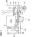
- FIG. 1 is a schematic view of an example air conditioning system 100 that may be used in accordance with aspects of the present invention.
- a vehicle may have an engine room 1 holding an engine 10 therein and a passenger compartment 2 separated from the engine room 1 by a dash panel 3.
- the air conditioning system 100 may have a refrigerant cycle device 100A including an expansion valve 131 and an evaporator 141, and an interior unit 100B. Components of the refrigerant cycle device 100A (usually excluding the expansion valve 131 and the evaporator 141) may be disposed in a predetermined mounting space of the engine room 1.
- the interior unit 100B may be arranged in an instrument panel placed in the passenger compartment 2.
- the interior unit 100B may include a blower 102, the evaporator 141, a heater 103, and an air conditioner case 101 housing the components of the interior unit 100B.
- the blower 102 may take in outside air or inside air selectively and send air to the evaporator 141 and the heater 103.
- the evaporator 141 is a cooling heat exchanger that evaporates a refrigerant used for a refrigeration cycle to make the evaporating refrigerant absorb latent heat of vaporization from air so as to cool the air.
- the heater 103 may use hot water (e.g., engine-cooling water) for cooling the engine 10 as heat source to heat air to be blown into the passenger compartment 2.
- An air mixing door 104 may be disposed near the heater 103 in the air conditioner case 101.
- the air mixing door 104 may be operated to adjust the mixing ratio between cool air cooled by the evaporator 141 and hot air heated by the heater 103 so that air having a desired temperature is sent into the passenger compartment 2.
- the refrigerant cycle device 100A may include a compressor 110, a condenser 120, the expansion valve 131 and the evaporator 141.
- Tubes 150 may connect those components of the refrigerant cycle device 100A to form a closed circuit.
- At least one double-wall tube 160 of the present invention may be placed in the tubes 150.
- the condenser 120 (for example a refrigerant radiator, gas cooler, or the like) may serve as a high-pressure heat exchanger for cooling high-pressure high-temperature refrigerant.
- the evaporator 141 may serve as a low-pressure heat exchanger and may be disposed to cool air passing therethrough.
- the expansion valve 131 is a pressure reducer, such as a throttle or an ejector.
- the compressor 110 is driven by the engine 10 to compress a low-pressure refrigerant to provide a high-temperature high- pressure refrigerant in the refrigerant cycle device 100A.
- a pulley 111 is attached to the drive shaft of the compressor 110.
- a drive belt 12 is extended between the pulley 111 and a crankshaft pulley 11 to drive the compressor 110 by the engine 10.
- the pulley 111 is linked to the drive shaft of the compressor 110 by an electromagnetic clutch (not shown).
- the electromagnetic clutch connects the pulley 111 to or disconnects the pulley 111 from the drive shaft of the compressor 110.
- the condenser 120 is connected to a discharge side of the compressor 110.
- the condenser 120 is a heat exchanger that cools the refrigerant by outside air to condense the refrigerant vapor into liquid refrigerant.
- the expansion valve 131 reduces the pressure of the refrigerant discharged from the condenser 120 and makes the refrigerant expand.
- the expansion valve 131 may be a pressure-reducing valve capable of reducing the pressure of the liquid refrigerant in an isentropic state.
- the expansion valve 131 included in the interior unit 100B usually is placed near the evaporator 141.
- the expansion valve 131 may be a temperature-controlled expansion valve having a variable orifice and may be capable of controlling the flow of the refrigerant discharged from the evaporator 141 and flowing into the compressor 110 so that the refrigerant is heated at a predetermined degree of superheat.
- the evaporator 141 is a cooling heat exchanger for cooling air to be blown into the passenger compartment.
- the discharge side of the evaporator 141 is connected to the suction side of the compressor 110.
- the double-wall tube 160 may be formed by combining a part of a high- pressure tube 151 and a part of a low-pressure tube 152 in the tubes 150.
- the high-pressure tube 151 extends between the condenser 120 and the expansion valve 131 to carry the high-pressure refrigerant before being decompressed.
- the low-pressure tube 152 extends between the evaporator 141 and the compressor 110 to carry a low-temperature low-pressure refrigerant after being decompressed and cooled.
- the following process may occur: when a passenger in a passenger compartment desires to operate the air conditioning system 100 for a cooling operation, an electromagnetic clutch may be engaged to drive the compressor 110 by the engine 10. Then, the compressor 110 sucks in the refrigerant discharged from the evaporator 141, compresses the refrigerant and discharges the high-temperature high-pressure refrigerant into the condenser120. The condenser 120 cools the high-temperature high-pressure refrigerant into a liquid refrigerant state with a substantially totally liquid phase.
- the liquid refrigerant from the condenser 120 flows into the expansion valve 131 through the liquid tube 164 connected to the double-wall tube 160, and through the annular space formed between the inner tube 162 and the outer tube 161 of the double-wall tube 160.
- the expansion valve 131 reduces the pressure of the liquid refrigerant and allows the liquid refrigerant to expand.
- the evaporator 141 evaporates the liquid refrigerant into a substantially saturated gas refrigerant.
- the refrigerant evaporated by the evaporator 141 absorbs heat from air flowing through the evaporator 141 to cool the air to be blown into the passenger compartment.
- the saturated gas refrigerant evaporated by the evaporator 141 that is, the lower-temperature low-pressure refrigerant, flows through the suction tube, the inner tube 162 and the suction tube into the compressor 110.
- Heat is transferred from the higher-temperature higher-pressure refrigerant (up to about 600 Psi, for example) flowing through the double-wall tube 160 to the lower-temperature lower-pressure refrigerant flowing through double-wall tube 160. Consequently, in the double-wall tube 160, the higher- temperature higher-pressure refrigerant is cooled and the lower-temperature lower-pressure refrigerant is heated.
- the liquid refrigerant discharged from the condenser 120 typically is sub-cooled and the temperature thereof drops while the liquid refrigerant is flowing through the double-wall tube 160.
- the saturated gaseous refrigerant discharged from the evaporator 141 typically is superheated into a gaseous refrigerant having a degree of superheat.
- the double-wall tube heat exchanger 160 is shown in accordance with the invention.
- the outer tube 161 is shown in ghost-lines so that interior components of the heat exchanger can be seen as well.
- a helically wound spring or other spiral element 170 may be wound around the inner tube 162 and defines, along with the inner surface of the outer tube 161 and the outer surface of the inner tube 162, a helical passageway for flow of fluid (for example, liquid refrigerant).
- the spiral element 170 may be tightly wound or otherwise in direct or indirect thermal contact with the inner tube162 in order to improve thermal conductivity therebetween.
- the outer surface of the inner tube 162 may be smooth in order to maximize the contact area with the spiral element 170 wrapped around it.
- the inner, outer and spiral element each may be of uniform diameter at least over the axially coextensive portions thereof.
- the spiral element may be held tightly against the outer diameter of the inner tube, such as for example by the inherent resiliency of the spiral element which may be in the form of a spring. More particularly, the spiral element may have when not assembled to the inner tube (unsprung state) an inner diameter less than the outer diameter of the inner tube such that the inner tube such that spiral element can be resiliently expanded to slip over the inner tube and then released with the resiliency of the spiral element causing the spiral element to contract around the inner tube and be held to the inner tube under a radially inward biasing force.
- the spiral element 170 may be made from a material having a high thermal conductivity, for example metallic material such as, for example, aluminum.
- Inner and outer tubes 162 and 161 may also be made of thermally conductive materials, for example metallic materials such as, for example, aluminum.
- the outer tube 161 has an inlet 180 and an outlet 181.
- the inlet 180 may be connected to, for example, the condenser 120 of the air-conditioning system100.
- the liquid is therefore forced to sweep the outer surface of the inner tube 162 and the spiral element 170 along a helical path.
- This flow path may have a reduced cross-sectional area as compared with a double-wall heat exchanger without a spiral element of corresponding size.
- This reduced cross-sectional area flow path increases the velocity of fluid flow and, therefore, increases the effectiveness of the convection cooling.
- the helical flow path increases the length of the flow path, as compared with a double-wall heat exchanger without the spiral element, while using the same amount of physical space. The increased length of the flow path may also increase the efficiency of the heat transfer occurring in the heat exchanger 160.
- the spiral element 170 may be thermally isolated from the inner surface of the outer tube 161 as illustrated in FIG. 3A .
- This thermal isolation may be accomplished by, for example, an annular gap 175 between the outer tube 161 and the spiral element 170.
- This gap may thus forma bypass flow path.
- the bypass flow path may account for less than about 5% of the total flow between the inner and outer tubes 162, 161. More preferably, the bypass flow path may account for less than about 1 % of the total flow between the inner and outer tubes 162, 161.
- This thermal isolation may exhibit surprising performance by, for example, preventing conduction from the outer tube 161 to the spiral element 170 and the inner tube 162.
- the thermal isolation may, for example, be accomplished by one or more layers of insulating material 185.
- the insulating material 185 may extend along substantially the entire inside surface of the outer tube 161, may extend along only the spiral element, or may be intermittently disposed along the length of the inside surface of the outer tube so as to act as a spacer.
- the outer tube 161 may be attached indirectly to the inner tube 162 by, for example, one or more end collars 190, as shown in FIGS. 2-4 .
- An end collar190 may be, for example, a cylindrical piece including a central bore 191 sized to fit around the outer surface of the inner tube 162.
- the end collar 190 may further include a first counter bore (or counter sink) 192 sized to be larger than the inner tube 162 but smaller than the outer surface of the outer tube 161.
- the collar 190 may include a second counter bore 193 sized to fit the outer surface of the outer tube 161.
- the collar 190 may have a radial hole or passage 195, 196 for acting as an inlet and/or outlet to the collar and the helical flow path.
- the radial hole may be located at the first counter bore 192.
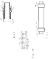
- the outer tube 161 may be directly attached to the inner tube by, for example swaging and/or welding as is shown in FIGS. 5-7 .
- the outer tube 161 may include a first and second radial hole 197, 198 for acting as an inlet and/or outlet to the helical flow path.
- Tubes made of a material other than aluminum, such as steel or copper, may be used instead of the tubes 161 and 162 made of aluminum.
- the spiral element may be free to move axially relative to at least one of the inner and outer tubes, and particularly the outer tube, so that the heat exchanger can be bent along its axial length without damaging the heat exchanger.
- the double-wall tube 160 of the invention has been described as used to the refrigerant cycle device 100A of the automotive air conditioning system 100, the present invention is not limited thereto in its practical application.
- the double-wall tube 160 may be suitably used for domestic air conditioners.
- the temperature of the atmosphere around the outer tube 161 is lower than that of air in the engine room 1. Therefore, the lower-pressure refrigerant can be set to pass through the space between the inner tube 162 and outer tube 161 and the higher-pressure refrigerant can be set to pass through the inside passage of the inner tube 162 when the heat transferring condition between the higher-pressure refrigerant and the lower-pressure refrigerant permits.
- the refrigerant that flows through the double-wall tube 160 is not limited to the refrigerant employed in the refrigerant cycle device 100A, a refrigerant having physical properties different from those of the refrigerant employed in the refrigerant cycle device 100A may be used. For example, refrigerant flowing in different directions, refrigerants respectively having different temperatures or refrigerants respectively having different pressures may be used in combination. Furthermore, different fluids other than the refrigerant of the refrigerant cycle device 100A can be used in the double-wall tube 160.
Landscapes
- Engineering & Computer Science (AREA)
- Physics & Mathematics (AREA)
- Thermal Sciences (AREA)
- Mechanical Engineering (AREA)
- General Engineering & Computer Science (AREA)
- Heat-Exchange Devices With Radiators And Conduit Assemblies (AREA)
Description
- This application claims the benefit of
U.S. Provisional Application No. 61/427,822 filed December 29, 2010 - The present invention relates to an internal heat exchanger, and more particularly to a double pipe internal heat exchanger for an automotive application wherein the pipes are separated by a spring or spiral element providing a helical outer fluid passageway. The invention relates, in particular, to a heat exchanger corresponding to the preamble of
claim 1, as disclosed inDE 20 2009 009 910 U1 . - Heat exchangers are often used in, for example, air conditioners that may used in motor vehicles, e.g. in the form of C02 air conditioners. An internal heat exchanger serves to transfer heat from the refrigerant on the high-pressure side to the refrigerant on the low-pressure side, whereby the so-called coefficient of performance, i.e., the ratio of refrigeration capacity and input power of the air conditioner, is significantly increased.
- Efficiency and performance gains may be achieved by the use of a coaxial heat exchanger where the liquid refrigerant flows around the outside of the suction tube. Heat is transferred from the liquid to the suction line which increases sub-cooling in the liquid line. However, known internal heat exchangers may not always maximize the heat transfer in a short compact length of suction line.
- The present invention provides a heat exchanger having an inner tube forming an inner flow path and having an inlet and an outlet; an outer tube radially surrounding at least a portion of the inner tube and spaced radially outwardly therefrom to form an annular space; and a thermally conductive spiral element wound around the inner tube and disposed in the space, wherein the spiral element is a spring, held tightly against the outer diameter of the inner tube by its inherent resiliency, wherein the spiral element forms, in conjunction with the inner tube and the outer tube, a helical flow path through the space, the helical flow path in fluid communication with an inlet and an outlet of the outer tube, and wherein the outer tube is thermally isolated from the spiral element.
- The outer tube may be thermally isolated from the spiral element by being spaced radially outwardly from the spiral element, forming a bypass flow path.
- The bypass flow path may accommodate less than about 5% of total flow through the bypass and helical flow paths.
- The bypass flow path may accommodate less than about 1 % of total flow through the bypass and helical flow paths.
- The outer tube may be thermally isolated from the spiral element by an insulation layer interposed between the spiral element and the outer tube.
- The spiral element is held tightly against the outer diameter of the inner tube such as by the inherent resiliency of the spiral element which is be in the form of a spring. More particularly, the spiral element may have when not assembled to the inner tube (unsprung state) an inner diameter less than the outer diameter of the inner tube such that the spiral element can be resiliently expanded to slip over the inner tube and then released with the resiliency of the spiral element causing the spiral element to contract around the inner tube and be held to the inner tube under a radially inward biasing force.
- The spiral element may be in contact with the inner tube for substantially all of the length of the spiral element.
- Axial ends of the outer tube may be welded to the inner tube. The outer tube may be connected to the inner tube by collars at respective axial ends of the outer tube.
- The spiral element may be free to move axially relative to at least one of the inner and outer tubes, and particularly the outer tube, so that the heat exchanger can be bent along its axial length without damaging the heat exchanger.
- The foregoing general features of the invention may apply individually or collectively to a heat exchanger according to another aspect of the invention, which heat exchanger includes an inner tube forming an inner flow path and having an inlet and an outlet; an outer tube radially surrounding at least portion of the inner tube and spaced radially outwardly therefrom to form an annular space; and a thermally conductive spiral element wound around the inner tube and disposed in the space, wherein the spiral element surrounds the inner tube and forms, in conjunction with the inner tube and the outer tube, a helical flow path through the annular space, the helical flow path in fluid communication with an inlet and an outlet of the outer tube, and wherein the spiral element continuously contacts the inner tube along a major length of the spiral element, and the spiral element is resiliently biased against the inner tube such that the spiral element is tightly held against the inner tube.
- The inner tube has an outer diameter surface that is smooth.
- The outer diameter surface is of uniform diameter along the length thereof surrounded by the spiral element.
- The foregoing general features of the invention may apply individually or collectively to a heat exchanger according to another aspect of the invention, which heat exchanger includes an inner tube forming an inner flow path and having an inlet and an outlet; an outer tube spaced radially outwardly of the inner tube and radially surrounding at least portion of the inner tube at an overlap region forming an annular space therein; a thermally conductive spiral element wound around the inner tube and disposed in the space of the overlap region; and a first collar configured to secure the outer tube to the inner tube at a first axial end of the outer tube, the first collar including a first radial hole; wherein the spiral element forms, in conjunction with the inner tube and the outer tube, a helical flow path through the space of the overlap region, and the helical flow path is in fluid communication with the first radial hole.
- The heat exchanger may further include a second collar configured to secure the outer tube to the inner tube at a second axial end of the outer tube, the second collar including a second radial hole, wherein the helical flow path is in fluid communication with the second radial hole.
- The first collar may include a central bore having a diameter substantially equal to an outer diameter of the inner tube, a first counter bore with a diameter intermediate of the diameter of the central bore and a diameter of a second counter bore, the diameter of the second counter bore being substantially equal to outside diameter of the outer tube, and wherein the central bore receives the inner tube and the second counter bore receives the outer tube therein.
- The first radial hole may be disposed in the first counter bore.
- The outer tube may be thermally isolated from the spiral element.
- The foregoing and other features of the invention are hereinafter described in greater detail with reference to the accompanying drawings.
-
-
FIG. 1 is a schematic view of an automotive air conditioning system; -
FIG. 2 is a perspective view of a heat exchanger in accordance with the present invention including the outer tube and collars shown in ghost lines; -
FIG. 3 is a partial cross-sectional view of the heat exchanger; -
FIG. 3A is an enlarged portion ofFIG. 3 , but showing an adaption of the heat exchanger wherein an inner spiral element is spaced from and thus relatively thermally isolated with respect to the outer tube; -
FIG. 4 is a side view of the heat exchanger; -
FIG. 5 is a perspective view of another heat exchanger in accordance with the present invention including the outer tube shown in ghost lines; -
FIG. 6 is a partial cross-sectional view of the heat exchanger ofFIG. 5 ; -
FIG. 7 is a side view of the heat exchanger ofFIG. 5 . - A heat exchanger in accordance with the present invention may be used in a number of applications, but, for ease of explanation and comprehension, will be described herein in reference to an air conditioning system for use in an automobile. Further, the use of the terms pipe and tube and the like (tubular members) are used interchangeably and do not necessarily denote a limiting definition unless the context demands otherwise. Also, the term "spiral" is intended to encompass "helical" and is used interchangeably therewith.
-
FIG. 1 is a schematic view of an example air conditioning system 100 that may be used in accordance with aspects of the present invention. A vehicle may have anengine room 1 holding anengine 10 therein and apassenger compartment 2 separated from theengine room 1 by adash panel 3. The air conditioning system 100 may have arefrigerant cycle device 100A including anexpansion valve 131 and anevaporator 141, and aninterior unit 100B. Components of therefrigerant cycle device 100A (usually excluding theexpansion valve 131 and the evaporator 141) may be disposed in a predetermined mounting space of theengine room 1. Theinterior unit 100B may be arranged in an instrument panel placed in thepassenger compartment 2. - The
interior unit 100B may include ablower 102, theevaporator 141, aheater 103, and anair conditioner case 101 housing the components of theinterior unit 100B. Theblower 102 may take in outside air or inside air selectively and send air to theevaporator 141 and theheater 103. Theevaporator 141 is a cooling heat exchanger that evaporates a refrigerant used for a refrigeration cycle to make the evaporating refrigerant absorb latent heat of vaporization from air so as to cool the air. Theheater 103 may use hot water (e.g., engine-cooling water) for cooling theengine 10 as heat source to heat air to be blown into thepassenger compartment 2. - An
air mixing door 104 may be disposed near theheater 103 in theair conditioner case 101. Theair mixing door 104 may be operated to adjust the mixing ratio between cool air cooled by theevaporator 141 and hot air heated by theheater 103 so that air having a desired temperature is sent into thepassenger compartment 2. - The
refrigerant cycle device 100A may include acompressor 110, acondenser 120, theexpansion valve 131 and theevaporator 141. Tubes 150 may connect those components of therefrigerant cycle device 100A to form a closed circuit. At least one double-wall tube 160 of the present invention may be placed in thetubes 150. The condenser 120 (for example a refrigerant radiator, gas cooler, or the like) may serve as a high-pressure heat exchanger for cooling high-pressure high-temperature refrigerant. Theevaporator 141 may serve as a low-pressure heat exchanger and may be disposed to cool air passing therethrough. Theexpansion valve 131 is a pressure reducer, such as a throttle or an ejector. - In the illustrated example, the
compressor 110 is driven by theengine 10 to compress a low-pressure refrigerant to provide a high-temperature high- pressure refrigerant in therefrigerant cycle device 100A. Apulley 111 is attached to the drive shaft of thecompressor 110. Adrive belt 12 is extended between thepulley 111 and acrankshaft pulley 11 to drive thecompressor 110 by theengine 10. Thepulley 111 is linked to the drive shaft of thecompressor 110 by an electromagnetic clutch (not shown). The electromagnetic clutch connects thepulley 111 to or disconnects thepulley 111 from the drive shaft of thecompressor 110. Thecondenser 120 is connected to a discharge side of thecompressor 110. Thecondenser 120 is a heat exchanger that cools the refrigerant by outside air to condense the refrigerant vapor into liquid refrigerant. Theexpansion valve 131 reduces the pressure of the refrigerant discharged from thecondenser 120 and makes the refrigerant expand. Theexpansion valve 131 may be a pressure-reducing valve capable of reducing the pressure of the liquid refrigerant in an isentropic state. Theexpansion valve 131 included in theinterior unit 100B usually is placed near theevaporator 141. Theexpansion valve 131 may be a temperature-controlled expansion valve having a variable orifice and may be capable of controlling the flow of the refrigerant discharged from theevaporator 141 and flowing into thecompressor 110 so that the refrigerant is heated at a predetermined degree of superheat. As described above, theevaporator 141 is a cooling heat exchanger for cooling air to be blown into the passenger compartment. The discharge side of theevaporator 141 is connected to the suction side of thecompressor 110. - The double-
wall tube 160 may be formed by combining a part of a high-pressure tube 151 and a part of a low-pressure tube 152 in thetubes 150. The high-pressure tube 151 extends between thecondenser 120 and theexpansion valve 131 to carry the high-pressure refrigerant before being decompressed. - The low-pressure tube 152 extends between the
evaporator 141 and thecompressor 110 to carry a low-temperature low-pressure refrigerant after being decompressed and cooled. - For example, when the above-described air conditioning system is implemented, the following process may occur: when a passenger in a passenger compartment desires to operate the air conditioning system 100 for a cooling operation, an electromagnetic clutch may be engaged to drive the
compressor 110 by theengine 10. Then, thecompressor 110 sucks in the refrigerant discharged from theevaporator 141, compresses the refrigerant and discharges the high-temperature high-pressure refrigerant into the condenser120. Thecondenser 120 cools the high-temperature high-pressure refrigerant into a liquid refrigerant state with a substantially totally liquid phase. The liquid refrigerant from thecondenser 120 flows into theexpansion valve 131 through the liquid tube 164 connected to the double-wall tube 160, and through the annular space formed between theinner tube 162 and theouter tube 161 of the double-wall tube 160. Theexpansion valve 131 reduces the pressure of the liquid refrigerant and allows the liquid refrigerant to expand. Theevaporator 141 evaporates the liquid refrigerant into a substantially saturated gas refrigerant. - The refrigerant evaporated by the
evaporator 141 absorbs heat from air flowing through theevaporator 141 to cool the air to be blown into the passenger compartment. The saturated gas refrigerant evaporated by theevaporator 141, that is, the lower-temperature low-pressure refrigerant, flows through the suction tube, theinner tube 162 and the suction tube into thecompressor 110. - Heat is transferred from the higher-temperature higher-pressure refrigerant (up to about 600 Psi, for example) flowing through the double-
wall tube 160 to the lower-temperature lower-pressure refrigerant flowing through double-wall tube 160. Consequently, in the double-wall tube 160, the higher- temperature higher-pressure refrigerant is cooled and the lower-temperature lower-pressure refrigerant is heated. The liquid refrigerant discharged from thecondenser 120 typically is sub-cooled and the temperature thereof drops while the liquid refrigerant is flowing through the double-wall tube 160. The saturated gaseous refrigerant discharged from theevaporator 141 typically is superheated into a gaseous refrigerant having a degree of superheat. - Turing now to
FIGS. 2 and3 , the double-walltube heat exchanger 160 is shown in accordance with the invention. InFIG. 2 , theouter tube 161 is shown in ghost-lines so that interior components of the heat exchanger can be seen as well. - A helically wound spring or
other spiral element 170 may be wound around theinner tube 162 and defines, along with the inner surface of theouter tube 161 and the outer surface of theinner tube 162, a helical passageway for flow of fluid (for example, liquid refrigerant). Thespiral element 170 may be tightly wound or otherwise in direct or indirect thermal contact with the inner tube162 in order to improve thermal conductivity therebetween. For example, the outer surface of theinner tube 162 may be smooth in order to maximize the contact area with thespiral element 170 wrapped around it. The inner, outer and spiral element each may be of uniform diameter at least over the axially coextensive portions thereof. - As noted, the spiral element may be held tightly against the outer diameter of the inner tube, such as for example by the inherent resiliency of the spiral element which may be in the form of a spring. More particularly, the spiral element may have when not assembled to the inner tube (unsprung state) an inner diameter less than the outer diameter of the inner tube such that the inner tube such that spiral element can be resiliently expanded to slip over the inner tube and then released with the resiliency of the spiral element causing the spiral element to contract around the inner tube and be held to the inner tube under a radially inward biasing force.
- The
spiral element 170 may be made from a material having a high thermal conductivity, for example metallic material such as, for example, aluminum. Inner andouter tubes - The
outer tube 161 has an inlet 180 and an outlet 181. The inlet 180 may be connected to, for example, thecondenser 120 of the air-conditioning system100. The liquid is therefore forced to sweep the outer surface of theinner tube 162 and thespiral element 170 along a helical path. This flow path may have a reduced cross-sectional area as compared with a double-wall heat exchanger without a spiral element of corresponding size. This reduced cross-sectional area flow path increases the velocity of fluid flow and, therefore, increases the effectiveness of the convection cooling. Further, the helical flow path increases the length of the flow path, as compared with a double-wall heat exchanger without the spiral element, while using the same amount of physical space. The increased length of the flow path may also increase the efficiency of the heat transfer occurring in theheat exchanger 160. - The
spiral element 170 may be thermally isolated from the inner surface of theouter tube 161 as illustrated inFIG. 3A . This thermal isolation may be accomplished by, for example, anannular gap 175 between theouter tube 161 and thespiral element 170. This gap may thus forma bypass flow path. Preferably, the bypass flow path may account for less than about 5% of the total flow between the inner andouter tubes outer tubes outer tube 161 to thespiral element 170 and theinner tube 162. - Alternatively, the thermal isolation may, for example, be accomplished by one or more layers of insulating
material 185. The insulatingmaterial 185 may extend along substantially the entire inside surface of theouter tube 161, may extend along only the spiral element, or may be intermittently disposed along the length of the inside surface of the outer tube so as to act as a spacer. - The
outer tube 161 may be attached indirectly to theinner tube 162 by, for example, one ormore end collars 190, as shown inFIGS. 2-4 . An end collar190 may be, for example, a cylindrical piece including acentral bore 191 sized to fit around the outer surface of theinner tube 162. Theend collar 190 may further include a first counter bore (or counter sink) 192 sized to be larger than theinner tube 162 but smaller than the outer surface of theouter tube 161. Finally, thecollar 190 may include a second counter bore 193 sized to fit the outer surface of theouter tube 161. Thecollar 190 may have a radial hole orpassage - Alternatively, the
outer tube 161 may be directly attached to the inner tube by, for example swaging and/or welding as is shown inFIGS. 5-7 . Theouter tube 161 may include a first and second radial hole 197, 198 for acting as an inlet and/or outlet to the helical flow path. - Although the flow through the outer helical path has been shown and described as being in the same direction as flow through the inner pipe, the flow may also be reversed, resulting in a counter-current flow of the gas and liquid phase refrigerant. Such a counter-current flow may be desirable in some cases and may result in different heat transfer efficiency.
- Tubes made of a material other than aluminum, such as steel or copper, may be used instead of the
tubes - Although the double-
wall tube 160 of the invention has been described as used to therefrigerant cycle device 100A of the automotive air conditioning system 100, the present invention is not limited thereto in its practical application. The double-wall tube 160 may be suitably used for domestic air conditioners. When the double-wall tube 160 is used for the domestic air conditioner, the temperature of the atmosphere around theouter tube 161 is lower than that of air in theengine room 1. Therefore, the lower-pressure refrigerant can be set to pass through the space between theinner tube 162 andouter tube 161 and the higher-pressure refrigerant can be set to pass through the inside passage of theinner tube 162 when the heat transferring condition between the higher-pressure refrigerant and the lower-pressure refrigerant permits. - The refrigerant that flows through the double-
wall tube 160 is not limited to the refrigerant employed in therefrigerant cycle device 100A, a refrigerant having physical properties different from those of the refrigerant employed in therefrigerant cycle device 100A may be used. For example, refrigerant flowing in different directions, refrigerants respectively having different temperatures or refrigerants respectively having different pressures may be used in combination. Furthermore, different fluids other than the refrigerant of therefrigerant cycle device 100A can be used in the double-wall tube 160. - Although the invention has been shown and described with respect to a certain embodiment or embodiments, it is obvious that equivalent alterations and modifications will occur to others skilled in the art upon the reading and understanding of this specification and the annexed drawings. In particular regard to the various functions performed by the above described elements (components, assemblies, devices, compositions, etc.), the terms (including a reference to a "means") used to describe such elements are intended to correspond, unless otherwise indicated, to any element which performs the specified function of the described element (i.e., that is functionally equivalent), even though not structurally equivalent to the disclosed structure which performs the function in the herein illustrated exemplary embodiment or embodiments of the invention. In addition, while a particular feature of the invention may have been described above with respect to only one or more of several illustrated embodiments, such feature may be combined with one or more other features of the other embodiments, as may be desired and advantageous for any given or particular application.
Claims (16)
- A heat exchanger (160) comprising:an inner tube (162) forming an inner flow path and having an inlet (180) and an outlet (181);an outer tube (161) radially surrounding at least portion of the inner tube (162) and spaced radially outwardly therefrom to form an annular space; anda thermally conductive spiral element (170) wound around the inner tube (162) and disposed in the space,wherein the spiral element (170) forms, in conjunction with the inner tube (162) and the outer tube (161), a helical flow path through the space, the helical flow path in fluid communication with an inlet (195) and an outlet (196) of the outer tube (161), andwherein the outer tube (161) is thermally isolated from the spiral element 170), the heat exchanger being characterized in that the spiral element (170) is a spring held tightly against the outer diameter of the inner tube (162) by its inherent resiliency.
- The heat exchanger (160) of claim 1, wherein the outer tube (161) is thermally isolated from the spiral element (170) by being spaced radially outwardly from the spiral element (170), forming an annular gap (175) defining a bypass flow path.
- The heat exchanger (160) of claim 2, wherein the bypass flow path accommodates less than about 5% of total flow through the bypass and helical flow paths.
- The heat exchanger (160) of either of claims 2 or 3, wherein the bypass flow path accommodates less than about 1 % of total flow through the bypass and helical flow paths.
- The heat exchanger (160) of any preceding claim, wherein the inner tube (162) has an outer diameter surface that is smooth.
- The heat exchanger (160) of any preceding claim, wherein the outer diameter surface is of uniform diameter along the length thereof surrounded by the spiral element (170).
- The heat exchanger (160) of any of the preceding claims, wherein the outer tube (161) is thermally isolated from the spiral element (170) by an insulation layer (185).
- The heat exchanger (160) of claim 7, wherein the insulating layer (185) extends along substantially the entire inside surface of the outer tube (161), extends along only the spiral element (170), or is intermittently disposed along the length of the inside surface of the outer tube (161) so as to act as a spacer.
- The heat exchanger (160) of any of the preceding claims, wherein the turns of the spiral element (170) are axially spaced apart.
- The heat exchanger (160) of any one of claims 1 -4 or 7-9, wherein the spiral element (170) is in contact with the inner tube (162) for substantially all of the length of the spiral element (170).
- The heat exchanger (160) of any of the preceding claims, wherein axial ends of the outer tube (161) are welded to the inner tube (162).
- The heat exchanger (160) of any of the preceding claims, wherein the outer tube (161) is connected to the inner tube (162) by collars (190) at respective axial ends of the outer tube (161).
- The heat exchanger (160) of any of the preceding claims, further comprising a first collar (190) configured to secure the outer tube (161) to the inner tube (162) at a first axial end of the outer tube (161), the first collar (190) including a first radial hole (195) and the helical flow path is in fluid communication with the first radial hole (195).
- The heat exchanger (160) of claim 13, further comprising a second collar (190) configured to secure the outer tube (161) to the inner tube (162) at a second axial end of the outer tube (161), the second collar (190) including a second radial hole (196), wherein the helical flow path is in fluid communication with the second radial hole (196).
- The heat exchanger (160) of claim 14, wherein the first collar (190) includes a central bore (191) having a diameter substantially equal to an outer diameter of the inner tube (162), a first counter bore (192) with a diameter intermediate of the diameter of the central bore (191) and a diameter of a second counter bore (193), the diameter of the second counter bore (193) being substantially equal to outside diameter of the outer tube (161), and wherein the central bore (191) receives the inner tube (162) and the second counter bore (193) receives the outer tube (161) therein.
- The heat exchanger (160) of claim 15, wherein the first radial hole (195) is disposed in the first counter bore (192).
Applications Claiming Priority (2)
| Application Number | Priority Date | Filing Date | Title |
|---|---|---|---|
| US201061427822P | 2010-12-29 | 2010-12-29 | |
| PCT/US2011/067775 WO2012092454A1 (en) | 2010-12-29 | 2011-12-29 | Internal heat exchanger |
Publications (2)
| Publication Number | Publication Date |
|---|---|
| EP2659215A1 EP2659215A1 (en) | 2013-11-06 |
| EP2659215B1 true EP2659215B1 (en) | 2019-02-27 |
Family
ID=45722688
Family Applications (1)
| Application Number | Title | Priority Date | Filing Date |
|---|---|---|---|
| EP11819176.6A Active EP2659215B1 (en) | 2010-12-29 | 2011-12-29 | Internal heat exchanger |
Country Status (4)
| Country | Link |
|---|---|
| EP (1) | EP2659215B1 (en) |
| KR (1) | KR102018855B1 (en) |
| CN (1) | CN103348208A (en) |
| WO (1) | WO2012092454A1 (en) |
Family Cites Families (8)
| Publication number | Priority date | Publication date | Assignee | Title |
|---|---|---|---|---|
| JP2006071270A (en) * | 2004-08-06 | 2006-03-16 | Showa Denko Kk | Heat exchanger, intermediate heat exchanger, and refrigeration cycle |
| DE102005052974B4 (en) * | 2004-11-09 | 2013-03-21 | Denso Corporation | Double walled pipe |
| JP2007032949A (en) * | 2005-07-28 | 2007-02-08 | Showa Denko Kk | Heat exchanger |
| JP2007232338A (en) * | 2006-02-28 | 2007-09-13 | Atago Seisakusho:Kk | Double tube type heat exchanger |
| AT503663B1 (en) * | 2006-07-28 | 2007-12-15 | Econicsystems Innovative Kuehl | SPIRAL HEAT TRANSFER AND METHOD FOR THE PRODUCTION THEREOF |
| FR2915561B1 (en) * | 2007-04-27 | 2009-06-26 | Hutchinson Sa | INTERNAL THERMAL EXCHANGER FOR A MOTOR VEHICLE AIR CONDITIONING CIRCUIT, ONE SUCH CIRCUIT AND METHOD FOR CONNECTING TWO CONNECTORS TO THIS EXCHANGER |
| JP2009162395A (en) * | 2007-12-28 | 2009-07-23 | Showa Denko Kk | Double-wall-tube heat exchanger |
| DE202009009910U1 (en) * | 2009-07-21 | 2009-09-24 | Truma Gerätetechnik GmbH & Co. KG | Heat exchanger with flow diverter |
-
2011
- 2011-12-29 CN CN2011800637404A patent/CN103348208A/en active Pending
- 2011-12-29 EP EP11819176.6A patent/EP2659215B1/en active Active
- 2011-12-29 WO PCT/US2011/067775 patent/WO2012092454A1/en not_active Ceased
- 2011-12-29 KR KR1020137019985A patent/KR102018855B1/en active Active
Non-Patent Citations (1)
| Title |
|---|
| None * |
Also Published As
| Publication number | Publication date |
|---|---|
| CN103348208A (en) | 2013-10-09 |
| WO2012092454A1 (en) | 2012-07-05 |
| KR102018855B1 (en) | 2019-09-05 |
| EP2659215A1 (en) | 2013-11-06 |
| KR20140025334A (en) | 2014-03-04 |
Similar Documents
| Publication | Publication Date | Title |
|---|---|---|
| JP4114471B2 (en) | Refrigeration cycle equipment | |
| US20060096314A1 (en) | Double-wall pipe and refrigerant cycle device using the same | |
| US8156754B2 (en) | Carbon dioxide refrigerant-coolant heat exchanger | |
| CN101946137B (en) | Refrigerant vapor compression system | |
| KR101797176B1 (en) | Dual pipe structure for internal heat exchanger | |
| CN1979081A (en) | Compound tube and method of producing the same | |
| CN105004087A (en) | Coolant circuit | |
| US11506459B2 (en) | Double pipe | |
| CN105960567A (en) | Two-phase refrigeration system | |
| CN110249189A (en) | Refrigerant piping and refrigerating circulatory device | |
| KR20150080570A (en) | REFRIGERANT CIRCUIT FOR A VEHICLE AIR-CONDITIONING SYSTEM AND METHOD OF AlR-CONDITIONING A VEHICLE INTERIOR | |
| JP2001056188A (en) | Heat exchanger used in vapor pressurizing type refrigeration cycle and the like | |
| JP4246189B2 (en) | Refrigeration cycle equipment | |
| US20130299143A1 (en) | Internal heat exchanger | |
| WO2018043097A1 (en) | Double pipe | |
| US8820111B2 (en) | De-super heater chiller system with contra flow and refrigerating fan grill | |
| CN100460794C (en) | Double-walled tube, manufacturing method thereof, and refrigerant cycle device provided with double-walled tube | |
| JP2010127498A (en) | Refrigerating cycle device | |
| KR102018855B1 (en) | Internal heat exchanger | |
| GB2508842A (en) | Double wall tube heat exchanger | |
| KR20170109463A (en) | Double pipe heat exchanger method of maufacturing and the double pipe | |
| US20140116082A1 (en) | Heat exchange apparatus | |
| JP2006183889A (en) | Heat pump device | |
| JP2007071529A (en) | Refrigeration cycle equipment | |
| JP2009204183A (en) | Refrigerating cycle device |
Legal Events
| Date | Code | Title | Description |
|---|---|---|---|
| PUAI | Public reference made under article 153(3) epc to a published international application that has entered the european phase |
Free format text: ORIGINAL CODE: 0009012 |
|
| 17P | Request for examination filed |
Effective date: 20130729 |
|
| AK | Designated contracting states |
Kind code of ref document: A1 Designated state(s): AL AT BE BG CH CY CZ DE DK EE ES FI FR GB GR HR HU IE IS IT LI LT LU LV MC MK MT NL NO PL PT RO RS SE SI SK SM TR |
|
| DAX | Request for extension of the european patent (deleted) | ||
| STAA | Information on the status of an ep patent application or granted ep patent |
Free format text: STATUS: EXAMINATION IS IN PROGRESS |
|
| 17Q | First examination report despatched |
Effective date: 20180320 |
|
| GRAP | Despatch of communication of intention to grant a patent |
Free format text: ORIGINAL CODE: EPIDOSNIGR1 |
|
| STAA | Information on the status of an ep patent application or granted ep patent |
Free format text: STATUS: GRANT OF PATENT IS INTENDED |
|
| INTG | Intention to grant announced |
Effective date: 20181031 |
|
| GRAS | Grant fee paid |
Free format text: ORIGINAL CODE: EPIDOSNIGR3 |
|
| GRAA | (expected) grant |
Free format text: ORIGINAL CODE: 0009210 |
|
| STAA | Information on the status of an ep patent application or granted ep patent |
Free format text: STATUS: THE PATENT HAS BEEN GRANTED |
|
| AK | Designated contracting states |
Kind code of ref document: B1 Designated state(s): AL AT BE BG CH CY CZ DE DK EE ES FI FR GB GR HR HU IE IS IT LI LT LU LV MC MK MT NL NO PL PT RO RS SE SI SK SM TR |
|
| REG | Reference to a national code |
Ref country code: GB Ref legal event code: FG4D |
|
| REG | Reference to a national code |
Ref country code: CH Ref legal event code: EP |
|
| REG | Reference to a national code |
Ref country code: DE Ref legal event code: R096 Ref document number: 602011056701 Country of ref document: DE |
|
| REG | Reference to a national code |
Ref country code: AT Ref legal event code: REF Ref document number: 1101981 Country of ref document: AT Kind code of ref document: T Effective date: 20190315 |
|
| REG | Reference to a national code |
Ref country code: IE Ref legal event code: FG4D |
|
| REG | Reference to a national code |
Ref country code: NL Ref legal event code: MP Effective date: 20190227 |
|
| REG | Reference to a national code |
Ref country code: LT Ref legal event code: MG4D |
|
| PG25 | Lapsed in a contracting state [announced via postgrant information from national office to epo] |
Ref country code: NL Free format text: LAPSE BECAUSE OF FAILURE TO SUBMIT A TRANSLATION OF THE DESCRIPTION OR TO PAY THE FEE WITHIN THE PRESCRIBED TIME-LIMIT Effective date: 20190227 Ref country code: SE Free format text: LAPSE BECAUSE OF FAILURE TO SUBMIT A TRANSLATION OF THE DESCRIPTION OR TO PAY THE FEE WITHIN THE PRESCRIBED TIME-LIMIT Effective date: 20190227 Ref country code: LT Free format text: LAPSE BECAUSE OF FAILURE TO SUBMIT A TRANSLATION OF THE DESCRIPTION OR TO PAY THE FEE WITHIN THE PRESCRIBED TIME-LIMIT Effective date: 20190227 Ref country code: PT Free format text: LAPSE BECAUSE OF FAILURE TO SUBMIT A TRANSLATION OF THE DESCRIPTION OR TO PAY THE FEE WITHIN THE PRESCRIBED TIME-LIMIT Effective date: 20190627 Ref country code: FI Free format text: LAPSE BECAUSE OF FAILURE TO SUBMIT A TRANSLATION OF THE DESCRIPTION OR TO PAY THE FEE WITHIN THE PRESCRIBED TIME-LIMIT Effective date: 20190227 Ref country code: NO Free format text: LAPSE BECAUSE OF FAILURE TO SUBMIT A TRANSLATION OF THE DESCRIPTION OR TO PAY THE FEE WITHIN THE PRESCRIBED TIME-LIMIT Effective date: 20190527 |
|
| PG25 | Lapsed in a contracting state [announced via postgrant information from national office to epo] |
Ref country code: IS Free format text: LAPSE BECAUSE OF FAILURE TO SUBMIT A TRANSLATION OF THE DESCRIPTION OR TO PAY THE FEE WITHIN THE PRESCRIBED TIME-LIMIT Effective date: 20190627 Ref country code: BG Free format text: LAPSE BECAUSE OF FAILURE TO SUBMIT A TRANSLATION OF THE DESCRIPTION OR TO PAY THE FEE WITHIN THE PRESCRIBED TIME-LIMIT Effective date: 20190527 Ref country code: RS Free format text: LAPSE BECAUSE OF FAILURE TO SUBMIT A TRANSLATION OF THE DESCRIPTION OR TO PAY THE FEE WITHIN THE PRESCRIBED TIME-LIMIT Effective date: 20190227 Ref country code: HR Free format text: LAPSE BECAUSE OF FAILURE TO SUBMIT A TRANSLATION OF THE DESCRIPTION OR TO PAY THE FEE WITHIN THE PRESCRIBED TIME-LIMIT Effective date: 20190227 Ref country code: GR Free format text: LAPSE BECAUSE OF FAILURE TO SUBMIT A TRANSLATION OF THE DESCRIPTION OR TO PAY THE FEE WITHIN THE PRESCRIBED TIME-LIMIT Effective date: 20190528 Ref country code: LV Free format text: LAPSE BECAUSE OF FAILURE TO SUBMIT A TRANSLATION OF THE DESCRIPTION OR TO PAY THE FEE WITHIN THE PRESCRIBED TIME-LIMIT Effective date: 20190227 |
|
| REG | Reference to a national code |
Ref country code: AT Ref legal event code: MK05 Ref document number: 1101981 Country of ref document: AT Kind code of ref document: T Effective date: 20190227 |
|
| PG25 | Lapsed in a contracting state [announced via postgrant information from national office to epo] |
Ref country code: AL Free format text: LAPSE BECAUSE OF FAILURE TO SUBMIT A TRANSLATION OF THE DESCRIPTION OR TO PAY THE FEE WITHIN THE PRESCRIBED TIME-LIMIT Effective date: 20190227 Ref country code: ES Free format text: LAPSE BECAUSE OF FAILURE TO SUBMIT A TRANSLATION OF THE DESCRIPTION OR TO PAY THE FEE WITHIN THE PRESCRIBED TIME-LIMIT Effective date: 20190227 Ref country code: SK Free format text: LAPSE BECAUSE OF FAILURE TO SUBMIT A TRANSLATION OF THE DESCRIPTION OR TO PAY THE FEE WITHIN THE PRESCRIBED TIME-LIMIT Effective date: 20190227 Ref country code: DK Free format text: LAPSE BECAUSE OF FAILURE TO SUBMIT A TRANSLATION OF THE DESCRIPTION OR TO PAY THE FEE WITHIN THE PRESCRIBED TIME-LIMIT Effective date: 20190227 Ref country code: CZ Free format text: LAPSE BECAUSE OF FAILURE TO SUBMIT A TRANSLATION OF THE DESCRIPTION OR TO PAY THE FEE WITHIN THE PRESCRIBED TIME-LIMIT Effective date: 20190227 Ref country code: RO Free format text: LAPSE BECAUSE OF FAILURE TO SUBMIT A TRANSLATION OF THE DESCRIPTION OR TO PAY THE FEE WITHIN THE PRESCRIBED TIME-LIMIT Effective date: 20190227 Ref country code: IT Free format text: LAPSE BECAUSE OF FAILURE TO SUBMIT A TRANSLATION OF THE DESCRIPTION OR TO PAY THE FEE WITHIN THE PRESCRIBED TIME-LIMIT Effective date: 20190227 Ref country code: EE Free format text: LAPSE BECAUSE OF FAILURE TO SUBMIT A TRANSLATION OF THE DESCRIPTION OR TO PAY THE FEE WITHIN THE PRESCRIBED TIME-LIMIT Effective date: 20190227 |
|
| REG | Reference to a national code |
Ref country code: DE Ref legal event code: R097 Ref document number: 602011056701 Country of ref document: DE |
|
| PG25 | Lapsed in a contracting state [announced via postgrant information from national office to epo] |
Ref country code: PL Free format text: LAPSE BECAUSE OF FAILURE TO SUBMIT A TRANSLATION OF THE DESCRIPTION OR TO PAY THE FEE WITHIN THE PRESCRIBED TIME-LIMIT Effective date: 20190227 Ref country code: SM Free format text: LAPSE BECAUSE OF FAILURE TO SUBMIT A TRANSLATION OF THE DESCRIPTION OR TO PAY THE FEE WITHIN THE PRESCRIBED TIME-LIMIT Effective date: 20190227 |
|
| PG25 | Lapsed in a contracting state [announced via postgrant information from national office to epo] |
Ref country code: AT Free format text: LAPSE BECAUSE OF FAILURE TO SUBMIT A TRANSLATION OF THE DESCRIPTION OR TO PAY THE FEE WITHIN THE PRESCRIBED TIME-LIMIT Effective date: 20190227 |
|
| PLBE | No opposition filed within time limit |
Free format text: ORIGINAL CODE: 0009261 |
|
| STAA | Information on the status of an ep patent application or granted ep patent |
Free format text: STATUS: NO OPPOSITION FILED WITHIN TIME LIMIT |
|
| 26N | No opposition filed |
Effective date: 20191128 |
|
| PG25 | Lapsed in a contracting state [announced via postgrant information from national office to epo] |
Ref country code: SI Free format text: LAPSE BECAUSE OF FAILURE TO SUBMIT A TRANSLATION OF THE DESCRIPTION OR TO PAY THE FEE WITHIN THE PRESCRIBED TIME-LIMIT Effective date: 20190227 |
|
| PG25 | Lapsed in a contracting state [announced via postgrant information from national office to epo] |
Ref country code: TR Free format text: LAPSE BECAUSE OF FAILURE TO SUBMIT A TRANSLATION OF THE DESCRIPTION OR TO PAY THE FEE WITHIN THE PRESCRIBED TIME-LIMIT Effective date: 20190227 |
|
| REG | Reference to a national code |
Ref country code: CH Ref legal event code: PL |
|
| REG | Reference to a national code |
Ref country code: BE Ref legal event code: MM Effective date: 20191231 |
|
| PG25 | Lapsed in a contracting state [announced via postgrant information from national office to epo] |
Ref country code: MC Free format text: LAPSE BECAUSE OF FAILURE TO SUBMIT A TRANSLATION OF THE DESCRIPTION OR TO PAY THE FEE WITHIN THE PRESCRIBED TIME-LIMIT Effective date: 20190227 |
|
| PG25 | Lapsed in a contracting state [announced via postgrant information from national office to epo] |
Ref country code: LU Free format text: LAPSE BECAUSE OF NON-PAYMENT OF DUE FEES Effective date: 20191229 Ref country code: IE Free format text: LAPSE BECAUSE OF NON-PAYMENT OF DUE FEES Effective date: 20191229 |
|
| PG25 | Lapsed in a contracting state [announced via postgrant information from national office to epo] |
Ref country code: BE Free format text: LAPSE BECAUSE OF NON-PAYMENT OF DUE FEES Effective date: 20191231 Ref country code: CH Free format text: LAPSE BECAUSE OF NON-PAYMENT OF DUE FEES Effective date: 20191231 Ref country code: LI Free format text: LAPSE BECAUSE OF NON-PAYMENT OF DUE FEES Effective date: 20191231 |
|
| PG25 | Lapsed in a contracting state [announced via postgrant information from national office to epo] |
Ref country code: CY Free format text: LAPSE BECAUSE OF FAILURE TO SUBMIT A TRANSLATION OF THE DESCRIPTION OR TO PAY THE FEE WITHIN THE PRESCRIBED TIME-LIMIT Effective date: 20190227 |
|
| PG25 | Lapsed in a contracting state [announced via postgrant information from national office to epo] |
Ref country code: MT Free format text: LAPSE BECAUSE OF FAILURE TO SUBMIT A TRANSLATION OF THE DESCRIPTION OR TO PAY THE FEE WITHIN THE PRESCRIBED TIME-LIMIT Effective date: 20190227 Ref country code: HU Free format text: LAPSE BECAUSE OF FAILURE TO SUBMIT A TRANSLATION OF THE DESCRIPTION OR TO PAY THE FEE WITHIN THE PRESCRIBED TIME-LIMIT; INVALID AB INITIO Effective date: 20111229 |
|
| REG | Reference to a national code |
Ref country code: DE Ref legal event code: R081 Ref document number: 602011056701 Country of ref document: DE Owner name: CONTITECH TECHNO-CHEMIE GMBH, DE Free format text: FORMER OWNER: CONTITECH KUEHNER GMBH & CIE. KG, 71570 OPPENWEILER, DE |
|
| PG25 | Lapsed in a contracting state [announced via postgrant information from national office to epo] |
Ref country code: MK Free format text: LAPSE BECAUSE OF FAILURE TO SUBMIT A TRANSLATION OF THE DESCRIPTION OR TO PAY THE FEE WITHIN THE PRESCRIBED TIME-LIMIT Effective date: 20190227 |
|
| REG | Reference to a national code |
Ref country code: GB Ref legal event code: 732E Free format text: REGISTERED BETWEEN 20231228 AND 20240103 |
|
| PGFP | Annual fee paid to national office [announced via postgrant information from national office to epo] |
Ref country code: GB Payment date: 20251219 Year of fee payment: 15 |
|
| PGFP | Annual fee paid to national office [announced via postgrant information from national office to epo] |
Ref country code: FR Payment date: 20251223 Year of fee payment: 15 |
|
| PGFP | Annual fee paid to national office [announced via postgrant information from national office to epo] |
Ref country code: DE Payment date: 20251231 Year of fee payment: 15 |