EP2658718B1 - Inlet manifold for an inkjet printhead - Google Patents
Inlet manifold for an inkjet printhead Download PDFInfo
- Publication number
- EP2658718B1 EP2658718B1 EP11805828.8A EP11805828A EP2658718B1 EP 2658718 B1 EP2658718 B1 EP 2658718B1 EP 11805828 A EP11805828 A EP 11805828A EP 2658718 B1 EP2658718 B1 EP 2658718B1
- Authority
- EP
- European Patent Office
- Prior art keywords
- ink
- manifold
- transverse channel
- printhead
- supply
- Prior art date
- Legal status (The legal status is an assumption and is not a legal conclusion. Google has not performed a legal analysis and makes no representation as to the accuracy of the status listed.)
- Active
Links
Images




Classifications
-
- B—PERFORMING OPERATIONS; TRANSPORTING
- B41—PRINTING; LINING MACHINES; TYPEWRITERS; STAMPS
- B41J—TYPEWRITERS; SELECTIVE PRINTING MECHANISMS, i.e. MECHANISMS PRINTING OTHERWISE THAN FROM A FORME; CORRECTION OF TYPOGRAPHICAL ERRORS
- B41J2/00—Typewriters or selective printing mechanisms characterised by the printing or marking process for which they are designed
- B41J2/005—Typewriters or selective printing mechanisms characterised by the printing or marking process for which they are designed characterised by bringing liquid or particles selectively into contact with a printing material
- B41J2/01—Ink jet
- B41J2/17—Ink jet characterised by ink handling
- B41J2/175—Ink supply systems ; Circuit parts therefor
-
- B—PERFORMING OPERATIONS; TRANSPORTING
- B41—PRINTING; LINING MACHINES; TYPEWRITERS; STAMPS
- B41J—TYPEWRITERS; SELECTIVE PRINTING MECHANISMS, i.e. MECHANISMS PRINTING OTHERWISE THAN FROM A FORME; CORRECTION OF TYPOGRAPHICAL ERRORS
- B41J2/00—Typewriters or selective printing mechanisms characterised by the printing or marking process for which they are designed
- B41J2/005—Typewriters or selective printing mechanisms characterised by the printing or marking process for which they are designed characterised by bringing liquid or particles selectively into contact with a printing material
- B41J2/01—Ink jet
- B41J2/015—Ink jet characterised by the jet generation process
- B41J2/04—Ink jet characterised by the jet generation process generating single droplets or particles on demand
- B41J2/06—Ink jet characterised by the jet generation process generating single droplets or particles on demand by electric or magnetic field
-
- B—PERFORMING OPERATIONS; TRANSPORTING
- B41—PRINTING; LINING MACHINES; TYPEWRITERS; STAMPS
- B41J—TYPEWRITERS; SELECTIVE PRINTING MECHANISMS, i.e. MECHANISMS PRINTING OTHERWISE THAN FROM A FORME; CORRECTION OF TYPOGRAPHICAL ERRORS
- B41J2/00—Typewriters or selective printing mechanisms characterised by the printing or marking process for which they are designed
- B41J2/005—Typewriters or selective printing mechanisms characterised by the printing or marking process for which they are designed characterised by bringing liquid or particles selectively into contact with a printing material
- B41J2/01—Ink jet
- B41J2/135—Nozzles
- B41J2/14—Structure thereof only for on-demand ink jet heads
- B41J2002/14419—Manifold
-
- B—PERFORMING OPERATIONS; TRANSPORTING
- B41—PRINTING; LINING MACHINES; TYPEWRITERS; STAMPS
- B41J—TYPEWRITERS; SELECTIVE PRINTING MECHANISMS, i.e. MECHANISMS PRINTING OTHERWISE THAN FROM A FORME; CORRECTION OF TYPOGRAPHICAL ERRORS
- B41J2202/00—Embodiments of or processes related to ink-jet or thermal heads
- B41J2202/01—Embodiments of or processes related to ink-jet heads
- B41J2202/12—Embodiments of or processes related to ink-jet heads with ink circulating through the whole print head
Definitions
- the present invention relates to an ink manifold structure for use in a printhead.
- WO 03/101741 describes a particular arrangement of printhead which comprises an ejector array mounted within a main body, to which an intermediate electrode plate is mounted. Ink is ejected from the ejector array by the action of an electric field generated between electrodes situated within the ejector array and the intermediate electrode as is well understood by the person skilled in the art.
- the ejector array is formed as a laminate structure which includes at least an ink inlet manifold, an ink inlet prism, a central tile and an ink outlet manifold.
- the central tile has the array of ejection points formed along its front edge and both the central tile and the prism include channels for supplying ink to the ejector array.
- a particular shape of ink manifold is chosen which provides desirable ink flow characteristics to and from the ejection locations of the ejection array.
- the shape of the inlet manifold of the printhead described in WO 03/101741 comprises a triangular chamber which is divergent in a direction from the inlet of the ink supply (i.e. the position within the manifold at which ink is input from a supply line) to the outlet (the outlet position being a front surface of the manifold along which ink is supplied to the array of ejection locations).
- the outlet manifold has a similar shape, but which is convergent in a direction from its inlet (which is the surface of the outlet manifold along which surplus ink is returned from the array of ejection locations) to its outlet (i.e. the position within the outlet manifold at which ink is output to a return line).
- the shape of the ink manifold described in WO 03/101741 results in inlet/outlet manifolds which have a relatively large width dimension from front to back (i.e. from the ink supply inlet into the inlet manifold to the front surface which connects to the array of the ejection locations or, for the outlet manifold, from the surface which connects to the array of the ejection locations to the ink output position). This necessarily results in a printhead which also has a relatively large width dimension from front to back.
- An object of the present invention is to provide a printhead having a significantly reduced width from front to back (i.e. the distance from the array of ejection locations to the rear of the printhead block), but which also retains and improves upon the desirable ink flow characteristics of the printhead described in WO 03/101741 .
- EP560110 discloses a particular arrangement of an ink manifold for a printhead where the adjacent transverse channel is not arranged between the inlet or outlet port and the first transverse channel.
- EP1884294 discloses an ink manifold with substantial vertical depth in which the channels snake from the bottom up to the top surface of the manifold.
- an ink manifold for an inkjet printhead which may comprise a substantially planar body which is longer in a length direction than a width direction and which has formed in a surface thereof: a first transverse channel for direct connection to ejection locations of said printhead along the length of the first channel, said first channel extending substantially parallel to the length direction of the body; and an adjacent transverse channel extending substantially parallel to the length direction of the body, said adjacent transverse channel being in fluid communication with a supply or sink of ink, and arranged to receive ink from the supply or pass ink to the sink, wherein the adjacent transverse channel is not directly connected to the ejection locations; wherein two or more connecting passages are arranged between adjacent ones of said transverse channels, operable to allow ink to flow between the transverse channels; wherein each connecting passage is sized such that it provides a greater flow restriction to ink flowing between the transverse channels than the restriction to flow of ink along the length of each transverse channel so that the pressure distribution
- said ink manifold may further comprise at least one further transverse channel, extending substantially parallel to the length direction of the body, and being connected between said adjacent transverse channel and said ink supply or sink via two or more additional connecting passages, wherein the adjacent transverse channel is in fluid communication with the supply or sink of ink via said at least one further transverse channel.
- One or more of the connecting passages connecting one pair of said transverse channels may be offset with respect to one or more of the connecting passages connecting an adjacent pair of channels.
- each channel may have a depth of 1 to 2 millimetres as measured from the surface of said body in which they are formed.
- each channel may also have a width substantially between 2 to 4 millimetres and a length substantially between 100 and 110 millimetres.
- each of the two or more connecting passages may have a depth of 0.5 millimetres as measured from the surface of said body into which it is formed.
- the two or more connecting passage may also have a length, as measured substantially parallel to the length of said channels, of between 2 to 10 millimetres and may have a width, said width being the distance between the adjacent channels which said passage connects, of 1 to 3 millimetres.
- the body has a thickness (measured from a top surface to a bottom surface of the body) of between approximately 9mm to 11mm, a width dimension (measured from the side of the body for connection to said ejection locations to the rear of the body opposite the ejection locations) of approximately 30mm, and a length dimension (measured along the side of the body along which the ejection locations are arrayed) of approximately 110mm to 170mm.
- the ink manifold of the present invention allows ink to flow from said adjacent transverse channel to ejection locations via the first transverse channel.
- the ink manifold of the present invention allows ink to flow from the ejection locations to said adjacent transverse channel via said first transverse channel.
- an electrostatic printhead comprising: a housing having an inlet for the supply of ink; an array of ejection locations for the ejection of ink droplets; and an ink supply pathway for the passage of ink from the inlet to the ejection locations, wherein the ink supply pathway may comprise the ink manifold of the first aspect of the present invention, said adjacent transverse channel being operable to receive ink from said inlet for the supply of ink.
- an electrostatic printhead comprising: a housing having an outlet for the removal of ink; an array of ejection locations for the ejection of ink droplets; and an ink removal pathway for the passage of ink from the ejection locations to the ink outlet, wherein the ink removal pathway may comprise the ink manifold according to the first aspect of the present invention, said adjacent transverse channel being operable to receive ink from said first transverse channel and supply ink to said outlet.
- an electrostatic printhead comprising: a housing having an inlet and an outlet for the supply and removal, respectively, of ink; an array of ejection locations for the ejection of ink droplets; an ink supply pathway for the passage of ink from the inlet to the ejection locations; and an ink removal pathway for the passage of ink from the ejection locations to the ink outlet, wherein the ink supply pathway may comprise the ink manifold according to any one of claims 1 to 10, said adjacent transverse channel being operable to receive ink from said inlet for the supply of ink, and wherein the ink removal pathway may comprise the ink manifold according to any one of claims 1 to 9 and 11, said adjacent transverse channel being operable to receive ink from said first transverse channel and supply ink to said outlet.
- the electrostatic printhead has a thickness of approximately 20mm measured from a top surface to a bottom surface of the printhead, a width dimension of approximately 46mm as measured from the ejection locations (317) to the rear of the printhead opposite the ejection locations (317), and a length dimension of approximately 148mm as measured along the side of the printhead along which the ejection locations (317) are arrayed.
- a method for use with an inkjet printhead comprising either: supplying ink to an ink manifold according to the first aspect of the present invention, said adjacent transverse channel being operable to receive ink from said inlet for the supply of ink; or receiving ink from an ink manifold according to the first aspect of the present invention where said adjacent transverse channel is operable to receive ink from said first transverse channel and supply ink to said outlet.
- the invention defined above advantageously provides an ink manifold which provides good ink flow characteristics to or from the ejection locations of a printhead, in terms of pressure distribution and flow rate, whilst reducing the distance from the front to the back of the ink manifold, i.e. the width of the ink manifold from the front (location of the ejection locations) to back (rear of the manifold opposite the ejection locations), thereby resulting in an ink manifold which is significantly smaller from front to back than conventional ink manifolds and which consequently, when incorporated into an electrostatic printhead, results in an electrostatic printhead which is significantly smaller from front to back (i.e. from the ink ejection portion of the printhead to the rear side of the printhead opposite the ejection locations) than conventional electrostatic printheads.
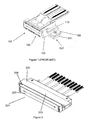
- the printhead shown in Figure 1 corresponds to a typical prior art printhead as described in WO 03/101741 .
- the printhead 101 comprises a main body 103 to which the remaining components are connected. Within the main body 103 is mounted an ejection portion consisting of a laminated structure that includes ink inlet and outlet manifolds and an ejector array. On one end of the main body 103, an intermediate electrode plate 105 is mounted by means of a kinematic mount.
- Figures 2 and 3 illustrate a printhead in accordance with the present invention.
- the printhead of the present invention shares a number of similarities with the prior art printhead described in WO 03/101741
- the shape of the printhead of the present invention is substantially different.
- the body of the printhead of the present invention is narrower from the front of the body where the ejection locations are provided to the rear of the body opposite the ejection locations by a factor of approximately 1.4 whilst the length of the array of ejectors is approximately 2.5 times longer than in a conventional body.
- the body of the printhead described in WO 03/101741 measures 64mm in width from the front where the ejection locations are provided to the back of the body opposite the ejection locations, it has a thickness of 25mm from top to bottom (i.e. the thickness measured perpendicular to the line of ejectors and perpendicular to the width dimension) and a length of 75mm as measured along the side of the body along which the ejection locations are arrayed whereas, in a preferred embodiment, the equivalent dimensions of the printhead of the present invention are 46 mm, 20 mm and 148 mm.
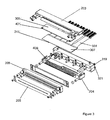
- the printhead 201 of the present invention comprises a two-part main body consisting of an inflow block 203 and an outflow block 204, between which are located a prism (309) and a central tile (307), the latter having the ejector array formed along its front edge.
- a prism (309)
- a central tile (307)
- the latter having the ejector array formed along its front edge.
- an intermediate electrode plate 205 is mounted on to a datum plate 206, which in turn is mounted onto the main body of the printhead by means of a kinematic mount.
- the main body of the printhead comprises the inflow block 203 and the outflow block 204, sandwiched between which are the prism 309 and the central tile 307.
- the central tile 307 has an array of ejection locations 317 along its front edge (not shown in Figure 3 ) and an array of electrical connections 331 along its rear edge.
- Each ejection location 317 comprises an upstand 400 with which an ink meniscus interacts (in a manner well known in the art).
- On either side of the upstand 400 is an ink channel 402 that carries ink past both sides of the ejection upstand 400.
- a proportion of ink is ejected from the ejection locations 317 to form, for example, the pixels of a printed image.
- the ejection of ink from the ejection locations 317 by the application of electrostatic forces is well understood by those of skill in the art and will not be described further herein.
- the prism 309 comprises a series of narrow channels 401, corresponding to each of the individual ejection locations 317 in the central tile 307 (in Figure 3 a representative portion of the channels 401 are illustrated at each end of the prism 309 but the skilled person will appreciate that the series of channels 401 extends across the entire face/width of the prism 309).
- the ink channels 402 of each ejection location 317 are in fluid communication with the respective channels 401 of the prism 309, which are, in turn, in fluid communication with a front portion of the inlet manifold 407 formed in the inflow block 203 (said inlet manifold 407 being formed on the underside of the inflow block 203 as it is presented in Figure 3 and thus not shown in that view).
- the ink channels 402 of the central tile 307 extend away from the ejection locations 317 on the underside of the central tile 307 to a point where they become in fluid communication with a front portion of the outlet manifold 409 formed in the outflow block 204.
- the ink is supplied to the ejection locations 317 by means of an ink supply tube 319 in the printhead 201 which feeds ink into the inlet manifold 407 within the inflow block 203.
- the ink passes through the inlet manifold 407 and from there through the channels 401 of the prism 309 to the ejection locations 317 on the central tile 307.
- Surplus ink that is not ejected from the ejection locations 317 in use then flows along the ink channels 402 of the central tile 307 into the outlet manifold 409 in the outflow block 204.
- the ink leaves the outlet manifold 409 through an ink return tube 321 and passes back into the bulk ink supply.
- the channels 401 of the prism 309 which are connected to the individual ejection locations 317 are supplied with ink from the inlet manifold 407 at a precise pressure in order to maintain accurately controlled ejection characteristics at the individual ejection locations 317.
- the pressure of the ink supplied to each individual channel 401 of the prism 309 by the ink inlet manifold 407 must be equal across the entire width of the array of ejection locations 317 of the printhead 201.
- the pressure of the ink returning from each individual channel 402 of the central tile 307 to the outlet manifold 409 must be equal across the entire width of the array of ejection locations 317, because the inlet and the outlet ink pressures together determine the quiescent pressure of ink at each ejection location 317.
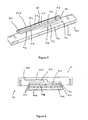
- Figures 5 and 6 show a perspective and plan view, respectively, of the inlet manifold of the present invention, shown upside down with respect to Figures 2 and 3 in order to reveal the detail of the manifold shape.
- the inflow block 203 is a substantially solid block which may be made of MACOR, alumina or other high stiffness material, chosen to impart precision and stability to the printhead assembly.
- the inflow block 203 is substantially longer in a first, length, direction (i.e.
- the inflow block is 9mm thick, has a width of approximately 30mm and has a length of 110mm. Mounting structures for joining the inflow block to the rest of the structural layers which make up the printhead, and for securing the printhead in the printer in which it operates, extend the overall length of the inflow block to approximately 170mm.
- the inflow block of the present invention is planar or substantially planar.
- the inlet manifold 407 is formed in the interior surface 701 of the inflow block 203 (that is, the surface that faces the prism 309 within the printhead assembly thus, in the arrangement illustrated in Figure 3 , the inlet manifold 407 is formed on the underside of the inflow block 203). It comprises three similar, transversely disposed channels that are substantially parallel to the long side of the inflow block 203 and which extend across the full width of the ejector array. These channels will be referred to as the front transverse channel 709, the intermediate transverse channel 713 and the rear transverse channel 711.
- the front transverse channel 709 is situated adjacent the front face 707 of the inflow block 203. From Figures 4A and 4B it can be seen that, when the inflow block 203 is assembled into the printhead, the front transverse channel 709 is directly connected to the array of ejection locations 317 in the central tile 307 via the channels 401 in the prism 309 which are in direct fluid communication with the front transverse channel 709.
- the intermediate and rear transverse channels 713, 711 which correspond in shape and appearance to the front transverse channel 709, are formed in the same surface 701 of the inflow block 203.
- the intermediate and rear transverse channels 713, 711 are arranged substantially parallel to the front transverse channel 709 and extend along the surface 701 of the inflow block 203 for the same length as the front transverse channel 709 thus completing the shape of the inlet manifold 407.
- the intermediate and rear transverse channels 713, 711 are in fluid communication with a supply of ink and are arranged to receive ink from the supply as will be described in more detail below. Neither of the intermediate or rear transverse channels 713, 711 are connected directly to the ejection locations.
- an ink supply port 703 into which the ink supply tube 319 fits and which feeds ink from the bulk supply to a supply channel 705 also formed in the same surface 701 of the inflow block 203 as the front, intermediate, and rear transverse channels 709, 711, 713.
- the ink supply port 703 is positioned on a face of the inflow block 203 towards one of the short sides of the inflow block 203 where it will not interfere with any of the electrical connections 331 to the central tile 307 where they emerge from the rear of the printhead, when the printhead is assembled.
- the supply channel 705 carries the ink from the ink supply port 703 to the mid-point of the rear transverse channel 711.
- an upper surface of the prism 309 lies flat against, and seals against, the surface 701 of the inflow block 203 in which the inlet manifold is formed thereby enclosing the channels 705, 709, 711, 713 formed in the surface of the inflow block 203.
- said channels of the inlet manifold are formed as channels in the surface 701 of the inflow block 203, they are separated by the material of the inflow block 203, located between each channel, which have not been channelled out of the surface of the inflow block.
- Each channel has a depth of between approximately 1 to 2 mm as measured from the surface 701 of the inflow block 203 and each extends approximately 100 to 110 mm in length. In a preferred embodiment, the depth of each of the channels is 1.5 mm as measured from the surface 701. Additionally, the width of each of the channels is preferably between approximately 2 to 5 mm.
- a plurality of passages 717 are formed through the separating region 715 which separates the rear and intermediate transverse channels 713, 711 from each other and further similar passages 719 are also formed through the separating region 715 which separates the intermediate transverse channel 713 from the front transverse channel 709.
- Each connecting passage allows ink to flow between the channels it connects.
- each connecting passage has a length, as measured substantially parallel to the length of the channels, between 2 to 10 mm.
- Each connecting passage has a width, being the distance between the channels which the connecting passage connects, of between 1 to 3 mm.
- Each connecting passage also has a depth, as measured from the surface of the inflow block of between 0.2 to 0.9 mm.
- each passage is approximately 5 mm long in the direction of the long side of the inflow block 203 and has a depth of approximately 0.5 millimetres measured from the surface 701 of the inflow block 203.
- each of the transverse channels 709, 711, 713 has a depth of approximately 1.5 millimetres as measured from the surface 701.
- the structure of the inlet manifold 407 thus formed has three comparatively deep, high volume channels (which are enclosed channels when the printhead is assembled) that form reservoirs where pressure is equalised by the transverse flow of ink (i.e. the ink spreads along the length of each of the transverse channels 709, 711, 713 perpendicular to the direction of general ink supply which is from the rear of the printhead where ink enters at the rear of the inflow block 203 to the front of the printhead where the ejection locations 317 are located).
- the transverse flow of ink i.e. the ink spreads along the length of each of the transverse channels 709, 711, 713 perpendicular to the direction of general ink supply which is from the rear of the printhead where ink enters at the rear of the inflow block 203 to the front of the printhead where the ejection locations 317 are located.
- the succession of three such transverse channels/reservoirs 709, 711, 713, separated by comparatively high-flow-resistance passages arrayed along the length of the transverse channels 709, 711, 713, provides for successively more uniform pressure across the length of the inlet manifold 407 until, at the exit of the front transverse channel 709 (i.e. where the front transverse channel 709 joins with the channels 401 in the prism 309), the pressure of ink entering each prism channel 401 is substantially equal.
- the front, intermediate, and rear transverse channels 709, 711, and 713 are substantially parallel to the longest side of the inlet manifold 407.
- the rear and intermediate transverse channels 711 and 713 and the rear edge of the front transverse channel 709 are actually angled by approximately 2 degrees measured from their mid-point towards the front edge 707 of the manifold.
- the intermediate and rear transverse channels, 711 and 713 have a uniform channel width (i.e.
- each of these two channels is angled along its length with respect to the front edge 707 of the inlet manifold towards it by approximately 2 degrees.
- the edge of the front transverse channel 709 closest to the front edge 707 of the manifold i.e. closest to the ejection locations
- the channel width of the front transverse channel 709 tapers along its length from a maximum width of approximately 4.2mm at the mid-point of the length of the channel to a minimum width of approximately 2.5mm at the two opposite ends of the length of the channel.
- a central passage 721 similar to the passages 717, exists between the rear and intermediate transverse channels 711 and 713 and the front transverse channel 709, through which air bubbles can be removed from the manifold via the supply channel 705.
- the outlet manifold 409 is substantially identical in principle and form to the inlet manifold 407 and is formed, in a similar way to that in which the inlet manifold 407 is formed in the inflow block 203, in a surface of the outflow block 204.
- the surface of the outflow block 204 in which the outlet manifold 409 is formed faces the underside of the central tile 307.
- the central tile 307 seals against the surface of the outflow block 204 in which the outlet manifold 409 is formed, thereby enclosing the channels of the outflow manifold 409 so that they effectively form enclosed tunnels rather than having an open surface.
- the outflow block 204 is a substantially solid block which may be made of MACOR, alumina or other high stiffness material, chosen to impart precision and stability to the printhead assembly.
- the outflow block 204 is substantially longer in a first, length, direction (i.e. the direction along which the ejection locations 317 are arrayed in the printhead 201) than in the width direction (where the width dimension is from the front of the outflow block i.e adjacent to the ejection locations to the back of the outflow block opposite the side nearest the ejection locations) or in a thickness direction measured from the top surface of the outflow block to the bottom surface of the outflow block.
- the outflow block is 10.9 mm thick, has a width of 30 mm, and has a length of 110 mm.
- Mounting structures for joining the outflow block to the rest of the structural layers which make up the printhead extend the overall length of the outflow block to approximately 148 mm.
- the dimensions of the channels and connecting passages formed in the outflow block are the same as those described in relation to the inflow block and the skilled person will see that the outflow block of the present invention is planar or substantially planar.
- the intermediate and rear transverse channels 713, 711 are in fluid communication with a sink of ink and are arranged to pass ink to the sink as will be described in more detail below.
- a continuous circulation of ink is established through the printhead from the ink supply 319 to the ink return 321.
- Ink is supplied to the inlet manifold 407 from the ink supply tube 319 which supplies ink to the supply channel 705 of the inlet manifold 407.
- Ink then flows through the supply channel 705 to the point where the supply channel 705 connects to the rear transverse manifold channel 711.
- Ink flows transversely, with little resistance to flow, along the rear transverse channel 711, creating a reasonably uniform ink pressure distribution along the length of the rear transverse channel 711.
- the components of the printhead are supplied with sufficient ink that all ink flow paths and/or conduits through the assembled printhead are entirely filled with ink. There are no free surfaces of ink within the assembled printhead other than the menisci presented at each of the ejection locations.
- Ink then flows from the rear transverse channel 711 into the intermediate transverse channel 713 via the passages 717 formed in the separating region 715 between the said rear and intermediate transverse channels 711, 713.
- the resistance to flow through the passages 717 is far higher than the resistance to flow along the rear and intermediate transverse channels 711, 713 themselves, so that ink enters the intermediate transverse channel 713 at a reasonably uniform pressure along its length across the inlet manifold.
- ink will again flow transversely along the length of the channel, flowing from the individual points of entry into the channel through the passages 717 through the separating region. As the ink spreads along the intermediate transverse channel the ink pressure along the length of the intermediate channel becomes more and more equalized.
- the ink then flows into the front transverse channel 709 via the passages 719 formed in the separating region 715 which separates the intermediate transverse channel 713 from the front transverse channel 709.
- the low resistance to flow transversely along the front transverse 709 channel equalises still further the pressure of ink along the length of the manifold.
- ink will flow into the array of ejection locations 317 via the prism 309 which is in fluid communication with the front transverse channel 709 of the inlet manifold 407 via the channels 401 formed in the prism.
- the printhead In use all of the ejectors 317 of the printhead are kept aligned in the same horizontal plane in order to equalise the hydrostatic component of pressure of the ink across the array of ejection locations.
- the printhead may be operated in a horizontal orientation as depicted in Figure 2 , a vertical orientation with the ejection locations pointing vertically downwards, or in any other orientation provided that all of the ejectors 317 are aligned across the same horizontal plane so that the ink therein experiences the same uniform hydrostatic pressure in each of the ejectors of the printhead. Effectively, the printhead is able to operate in any orientation which does not cause one ejector tip to be located higher or lower than any other ejector tip.
- surplus ink flows along the channels 402 in the central tile 307 to the outlet manifold 409 and then back to the bulk supply via the ink return tube 321.
- the outlet manifold 409 has a similar construction (i.e. front, intermediate, and rear transverse channels) to the inlet manifold 409, the pressure distribution of ink held within the front transverse channel of the outlet manifold (i.e. the channel which first receives any surplus ink from the channels 402 in the central tile 307) is substantially uniform.
- ink flowing into the front transverse channel from the central tile 307 finds the resistance to flow along the length of the front transverse channel to be less than the resistance to flow into the intermediate transverse channel presented by the passages through the separating region between the front and intermediate transverse channels.
- the arrangement of the outlet manifold of the present invention presents a substantially uniform and equal back pressure to the ejection locations 317 along the length of the outlet manifold.
- the pressure of ink at the ejection locations 317 is maintained slightly lower than ambient atmospheric pressure to ensure that the menisci of the free ink surfaces in the ejection locations 317 conform correctly to the features of the ejection locations 317 (this behaviour of the ink is known in the art as "pinning").
- the control of the pressure of ink at the ejection locations 317 is achieved by controlling the pressures of the ink entering the supply tube 319 and exiting the return tube 321, between which a continuous, unbroken circulation of ink is maintained through the printhead.
- the creation of a uniform pressure of ink across the full length of the array of ejection locations 317 is dependent on the abilities of both the inlet manifold 407 and the outlet manifold 409 to equalise pressure along their lengths.
- inlet manifold 407 works equally well at creating uniform pressure along its length regardless of the direction of ink flow through the manifold and, therefore, the design described in relation to the inlet manifold is also used for the outlet manifold 409 of the printhead.
- the inventors have found that the particular arrangement of the inlet manifold 407 described above provides a substantially equal pressure distribution of the ink in the front transverse channel 709 and thus provides the ink to each channel 401 of the prism 309 at substantially equal pressure along the length of the ejector array. It follows that the particular arrangement of inlet manifold 407 described above provides each individual channel 401 of the prism 309 with equal flow rate of ink.
- Figures 7 and 8 illustrate the flow rate distribution of ink within a manifold structure according to the present invention.
- FIGs have been produced with the manifold operating as an inlet manifold, the skilled person would readily appreciate that the pressure/flow rate distribution for the manifold operating as an outlet manifold would be identical to the Figures shown but with negative values.
- a substantially uniform flow rate from (or into, in the case that the manifold is used as an outlet manifold) the front transverse channel 709 as shown in Figure 8 also indicates substantially uniform pressure.
- Figures 9 and 10 show a similar flow rate distribution map and graph for the ink inlet manifold described in WO 03/101741 in which the inlet manifold is a divergent triangular cavity (as was the case for Figures 7 and 8 , only one half of the manifold has been modelled in Figures 9 and 10 , the other half being a reflection in the vertical plane at the origin). Comparing the two sets of results, i.e.
- the present invention results in manifolds 407, 409 and printhead 201 in which it is possible to supply ink to each of the ejection locations 317 in the array of ejection locations, and receive surplus ink from the ejection locations, at substantially equal pressure and flow rate across the entire length of the array of ejection locations.
- the manifolds and thus the printhead are able to be physically smaller from front to back than known printheads using conventional manifolds.
- more than the one intermediate transverse channel 713 could be supplied between the rear transverse channel 711 and the front transverse channel 709 provided that they conform to the substantially parallel arrangement required and provide the same low resistance to transverse ink flow along their lengths compared with the resistance to ink flow between respective ones of the intermediate channels presented by the passages 717, 719 through the separating regions between them.
- Figure 5 illustrates a manifold where the passages 717, 719 between each respective transverse channel are staggered (to provide stable support of the prism laminate 309) with respect to those in adjacent regions
- Figure 7 where the passages 717, 719 are illustrated as being aligned.
- the sizing and shape of the transverse channels and of the connecting passages between the passages gives each of those channels and passages a particular restriction to flow of liquid/ink therein.
- the present invention encompasses any shape or sizing of the channels and connecting passages provided that the connecting passages provide a greater flow restriction to ink passing therethrough than do the transverse channels.
- inlet channel 705, rear transverse channel 713, intermediate transverse channel 711 and front transverse channel 709 could be altered without departing from the scope of the invention provided that they remain connected to each other only by passages 717, 719 which present a higher resistance to flow than the flow resistance along the transverse channels.
- Figure 2 illustrates a typical printhead in which the ink manifold (either inlet or outlet) of the present invention may be employed
- the ink manifold either inlet or outlet
- the benefits provided by the manifold of the present invention (whether considering its use as an inlet manifold or as an outlet manifold) of supplying ink at a uniform pressure across the entire width of the ejector array will be realised.
Landscapes
- Particle Formation And Scattering Control In Inkjet Printers (AREA)
- Ink Jet (AREA)
Description
- The present invention relates to an ink manifold structure for use in a printhead.
- The general method of operation of the type of printhead described in
WO 93/11866 -
WO 03/101741 WO 03/101741 - The shape of the inlet manifold of the printhead described in
WO 03/101741 - Whilst providing desirable ink flow characteristics to the array of ejection locations, the shape of the ink manifold described in
WO 03/101741 - An object of the present invention is to provide a printhead having a significantly reduced width from front to back (i.e. the distance from the array of ejection locations to the rear of the printhead block), but which also retains and improves upon the desirable ink flow characteristics of the printhead described in
WO 03/101741 - A related invention is
EP560110 - Another invention,
EP1884294 , discloses an ink manifold with substantial vertical depth in which the channels snake from the bottom up to the top surface of the manifold. - In accordance with a first aspect of the present invention, an ink manifold for an inkjet printhead is provided which may comprise a substantially planar body which is longer in a length direction than a width direction and which has formed in a surface thereof: a first transverse channel for direct connection to ejection locations of said printhead along the length of the first channel, said first channel extending substantially parallel to the length direction of the body; and an adjacent transverse channel extending substantially parallel to the length direction of the body, said adjacent transverse channel being in fluid communication with a supply or sink of ink, and arranged to receive ink from the supply or pass ink to the sink, wherein the adjacent transverse channel is not directly connected to the ejection locations; wherein two or more connecting passages are arranged between adjacent ones of said transverse channels, operable to allow ink to flow between the transverse channels; wherein each connecting passage is sized such that it provides a greater flow restriction to ink flowing between the transverse channels than the restriction to flow of ink along the length of each transverse channel so that the pressure distribution of ink within said first transverse channel is substantially uniform along the length of said channel.
- Preferably, said ink manifold may further comprise at least one further transverse channel, extending substantially parallel to the length direction of the body, and being connected between said adjacent transverse channel and said ink supply or sink via two or more additional connecting passages, wherein the adjacent transverse channel is in fluid communication with the supply or sink of ink via said at least one further transverse channel. One or more of the connecting passages connecting one pair of said transverse channels may be offset with respect to one or more of the connecting passages connecting an adjacent pair of channels.
- Preferably, each channel may have a depth of 1 to 2 millimetres as measured from the surface of said body in which they are formed. Preferably, each channel may also have a width substantially between 2 to 4 millimetres and a length substantially between 100 and 110 millimetres.
- Preferably, each of the two or more connecting passages may have a depth of 0.5 millimetres as measured from the surface of said body into which it is formed. Preferably, the two or more connecting passage may also have a length, as measured substantially parallel to the length of said channels, of between 2 to 10 millimetres and may have a width, said width being the distance between the adjacent channels which said passage connects, of 1 to 3 millimetres.
- Preferably, the body has a thickness (measured from a top surface to a bottom surface of the body) of between approximately 9mm to 11mm, a width dimension (measured from the side of the body for connection to said ejection locations to the rear of the body opposite the ejection locations) of approximately 30mm, and a length dimension (measured along the side of the body along which the ejection locations are arrayed) of approximately 110mm to 170mm.
- Preferably, the ink manifold of the present invention allows ink to flow from said adjacent transverse channel to ejection locations via the first transverse channel. Alternatively, the ink manifold of the present invention allows ink to flow from the ejection locations to said adjacent transverse channel via said first transverse channel.
- In accordance with a further aspect of the present invention, an electrostatic printhead may be provided comprising: a housing having an inlet for the supply of ink; an array of ejection locations for the ejection of ink droplets; and an ink supply pathway for the passage of ink from the inlet to the ejection locations, wherein the ink supply pathway may comprise the ink manifold of the first aspect of the present invention, said adjacent transverse channel being operable to receive ink from said inlet for the supply of ink.
- In accordance with a further aspect of the present invention, an electrostatic printhead may be provided comprising: a housing having an outlet for the removal of ink; an array of ejection locations for the ejection of ink droplets; and an ink removal pathway for the passage of ink from the ejection locations to the ink outlet, wherein the ink removal pathway may comprise the ink manifold according to the first aspect of the present invention, said adjacent transverse channel being operable to receive ink from said first transverse channel and supply ink to said outlet.
- In accordance with a further aspect of the present invention, an electrostatic printhead may be provided comprising: a housing having an inlet and an outlet for the supply and removal, respectively, of ink; an array of ejection locations for the ejection of ink droplets; an ink supply pathway for the passage of ink from the inlet to the ejection locations; and an ink removal pathway for the passage of ink from the ejection locations to the ink outlet, wherein the ink supply pathway may comprise the ink manifold according to any one of
claims 1 to 10, said adjacent transverse channel being operable to receive ink from said inlet for the supply of ink, and wherein the ink removal pathway may comprise the ink manifold according to any one ofclaims 1 to 9 and 11, said adjacent transverse channel being operable to receive ink from said first transverse channel and supply ink to said outlet. - Preferably, the electrostatic printhead has a thickness of approximately 20mm measured from a top surface to a bottom surface of the printhead, a width dimension of approximately 46mm as measured from the ejection locations (317) to the rear of the printhead opposite the ejection locations (317), and a length dimension of approximately 148mm as measured along the side of the printhead along which the ejection locations (317) are arrayed.
- In accordance with a further aspect of the present invention, a method for use with an inkjet printhead may be provided comprising either: supplying ink to an ink manifold according to the first aspect of the present invention, said adjacent transverse channel being operable to receive ink from said inlet for the supply of ink; or receiving ink from an ink manifold according to the first aspect of the present invention where said adjacent transverse channel is operable to receive ink from said first transverse channel and supply ink to said outlet.
- The invention defined above advantageously provides an ink manifold which provides good ink flow characteristics to or from the ejection locations of a printhead, in terms of pressure distribution and flow rate, whilst reducing the distance from the front to the back of the ink manifold, i.e. the width of the ink manifold from the front (location of the ejection locations) to back (rear of the manifold opposite the ejection locations), thereby resulting in an ink manifold which is significantly smaller from front to back than conventional ink manifolds and which consequently, when incorporated into an electrostatic printhead, results in an electrostatic printhead which is significantly smaller from front to back (i.e. from the ink ejection portion of the printhead to the rear side of the printhead opposite the ejection locations) than conventional electrostatic printheads.
- Various embodiments of the invention will now be described with reference to the attached figures in which:
-
Figure 1 is a perspective view of a typical prior art printhead; -
Figure 2 is a perspective view of a printhead according to the present invention; -
Figure 3 is an exploded view of the printhead illustrated inFigure 2 ; -
Figure 4A is a schematic cross sectional view through the main body of the printhead illustrated inFigure 2 ; -
Figure 4B is a detailed cross sectional view of the ejection region of the printhead illustrated inFigure 2 ; -
Figure 5 is a perspective view of the inlet manifold according to the present invention; -
Figure 6 is a plan view of the inlet manifold according to the present invention; -
Figure 7 is a flow rate map of the velocity distribution of ink flow through the inlet manifold of the present invention; -
Figure 8 is a graph of ink flow velocity against position at the outlet of the manifold of the present invention; -
Figure 9 is a flow rate map of the velocity distribution of ink flow through a prior art inlet manifold; and -
Figure 10 is a graph of ink flow velocity against position at the outlet of the prior art manifold. - The printhead shown in
Figure 1 corresponds to a typical prior art printhead as described inWO 03/101741 printhead 101 comprises amain body 103 to which the remaining components are connected. Within themain body 103 is mounted an ejection portion consisting of a laminated structure that includes ink inlet and outlet manifolds and an ejector array. On one end of themain body 103, anintermediate electrode plate 105 is mounted by means of a kinematic mount. -
Figures 2 and3 illustrate a printhead in accordance with the present invention. Although the printhead of the present invention shares a number of similarities with the prior art printhead described inWO 03/101741 WO 03/101741 WO 03/101741 - The
printhead 201 of the present invention comprises a two-part main body consisting of aninflow block 203 and anoutflow block 204, between which are located a prism (309) and a central tile (307), the latter having the ejector array formed along its front edge. At the front of the printhead, anintermediate electrode plate 205 is mounted on to adatum plate 206, which in turn is mounted onto the main body of the printhead by means of a kinematic mount. - Referring to
figures 3 ,4A and4B , the main body of the printhead comprises theinflow block 203 and theoutflow block 204, sandwiched between which are theprism 309 and thecentral tile 307. Thecentral tile 307 has an array ofejection locations 317 along its front edge (not shown inFigure 3 ) and an array ofelectrical connections 331 along its rear edge. Eachejection location 317 comprises anupstand 400 with which an ink meniscus interacts (in a manner well known in the art). On either side of theupstand 400 is anink channel 402 that carries ink past both sides of the ejection upstand 400. In use, a proportion of ink is ejected from theejection locations 317 to form, for example, the pixels of a printed image. The ejection of ink from theejection locations 317 by the application of electrostatic forces is well understood by those of skill in the art and will not be described further herein. - The
prism 309 comprises a series ofnarrow channels 401, corresponding to each of theindividual ejection locations 317 in the central tile 307 (inFigure 3 a representative portion of thechannels 401 are illustrated at each end of theprism 309 but the skilled person will appreciate that the series ofchannels 401 extends across the entire face/width of the prism 309). Theink channels 402 of eachejection location 317 are in fluid communication with therespective channels 401 of theprism 309, which are, in turn, in fluid communication with a front portion of theinlet manifold 407 formed in the inflow block 203 (saidinlet manifold 407 being formed on the underside of theinflow block 203 as it is presented inFigure 3 and thus not shown in that view). Below theejection locations 317, theink channels 402 of thecentral tile 307 extend away from theejection locations 317 on the underside of thecentral tile 307 to a point where they become in fluid communication with a front portion of theoutlet manifold 409 formed in theoutflow block 204. - The ink is supplied to the
ejection locations 317 by means of anink supply tube 319 in theprinthead 201 which feeds ink into theinlet manifold 407 within theinflow block 203. The ink passes through theinlet manifold 407 and from there through thechannels 401 of theprism 309 to theejection locations 317 on thecentral tile 307. Surplus ink that is not ejected from theejection locations 317 in use then flows along theink channels 402 of thecentral tile 307 into theoutlet manifold 409 in theoutflow block 204. The ink leaves theoutlet manifold 409 through anink return tube 321 and passes back into the bulk ink supply. - The
channels 401 of theprism 309 which are connected to theindividual ejection locations 317 are supplied with ink from theinlet manifold 407 at a precise pressure in order to maintain accurately controlled ejection characteristics at theindividual ejection locations 317. The pressure of the ink supplied to eachindividual channel 401 of theprism 309 by theink inlet manifold 407 must be equal across the entire width of the array ofejection locations 317 of theprinthead 201. Similarly, the pressure of the ink returning from eachindividual channel 402 of thecentral tile 307 to theoutlet manifold 409 must be equal across the entire width of the array ofejection locations 317, because the inlet and the outlet ink pressures together determine the quiescent pressure of ink at eachejection location 317. -
Figures 5 and 6 show a perspective and plan view, respectively, of the inlet manifold of the present invention, shown upside down with respect toFigures 2 and3 in order to reveal the detail of the manifold shape. Theinflow block 203 is a substantially solid block which may be made of MACOR, alumina or other high stiffness material, chosen to impart precision and stability to the printhead assembly. Theinflow block 203 is substantially longer in a first, length, direction (i.e. the direction along which theejection locations 317 are arrayed in the printhead 201) than in the width direction (where the width dimension is from the front of the inflow block i.e adjacent to the ejection locations, to the back of the inflow block opposite the side nearest the ejection locations) or in a thickness direction measured from the top surface of the inflow block to the bottom surface of the inflow block. In a preferred embodiment, the inflow block is 9mm thick, has a width of approximately 30mm and has a length of 110mm. Mounting structures for joining the inflow block to the rest of the structural layers which make up the printhead, and for securing the printhead in the printer in which it operates, extend the overall length of the inflow block to approximately 170mm. The skilled person will see that the inflow block of the present invention is planar or substantially planar. - The
inlet manifold 407 is formed in theinterior surface 701 of the inflow block 203 (that is, the surface that faces theprism 309 within the printhead assembly thus, in the arrangement illustrated inFigure 3 , theinlet manifold 407 is formed on the underside of the inflow block 203). It comprises three similar, transversely disposed channels that are substantially parallel to the long side of theinflow block 203 and which extend across the full width of the ejector array. These channels will be referred to as the fronttransverse channel 709, the intermediatetransverse channel 713 and the reartransverse channel 711. - The front
transverse channel 709 is situated adjacent thefront face 707 of theinflow block 203. FromFigures 4A and4B it can be seen that, when theinflow block 203 is assembled into the printhead, the fronttransverse channel 709 is directly connected to the array ofejection locations 317 in thecentral tile 307 via thechannels 401 in theprism 309 which are in direct fluid communication with the fronttransverse channel 709. - The intermediate and rear
transverse channels transverse channel 709, are formed in thesame surface 701 of theinflow block 203. The intermediate and reartransverse channels transverse channel 709 and extend along thesurface 701 of theinflow block 203 for the same length as the fronttransverse channel 709 thus completing the shape of theinlet manifold 407. The intermediate and reartransverse channels transverse channels - At the rear of the
inflow block 203 is located anink supply port 703 into which theink supply tube 319 fits and which feeds ink from the bulk supply to asupply channel 705 also formed in thesame surface 701 of theinflow block 203 as the front, intermediate, and reartransverse channels ink supply port 703 is positioned on a face of theinflow block 203 towards one of the short sides of theinflow block 203 where it will not interfere with any of theelectrical connections 331 to thecentral tile 307 where they emerge from the rear of the printhead, when the printhead is assembled. Thesupply channel 705 carries the ink from theink supply port 703 to the mid-point of the reartransverse channel 711. - In the assembled printhead, an upper surface of the
prism 309 lies flat against, and seals against, thesurface 701 of theinflow block 203 in which the inlet manifold is formed thereby enclosing thechannels inflow block 203. This is illustrated inFigures 3 ,4A , and4B . As said channels of the inlet manifold are formed as channels in thesurface 701 of theinflow block 203, they are separated by the material of theinflow block 203, located between each channel, which have not been channelled out of the surface of the inflow block. These separatingregions 715 provide a barrier to ink flow between the front, intermediate, and reartransverse channels surface 701 of theinflow block 203 and each extends approximately 100 to 110 mm in length. In a preferred embodiment, the depth of each of the channels is 1.5 mm as measured from thesurface 701. Additionally, the width of each of the channels is preferably between approximately 2 to 5 mm. - A plurality of
passages 717 are formed through the separatingregion 715 which separates the rear and intermediatetransverse channels similar passages 719 are also formed through the separatingregion 715 which separates the intermediatetransverse channel 713 from the fronttransverse channel 709. Each connecting passage allows ink to flow between the channels it connects. - Furthermore, each connecting passage has a length, as measured substantially parallel to the length of the channels, between 2 to 10 mm. Each connecting passage has a width, being the distance between the channels which the connecting passage connects, of between 1 to 3 mm. Each connecting passage also has a depth, as measured from the surface of the inflow block of between 0.2 to 0.9 mm.
- In a preferred embodiment, each passage is approximately 5 mm long in the direction of the long side of the
inflow block 203 and has a depth of approximately 0.5 millimetres measured from thesurface 701 of theinflow block 203. In this preferred embodiment, by comparison, each of thetransverse channels surface 701. - Hence the skilled person will appreciate that the structure of the
inlet manifold 407 thus formed has three comparatively deep, high volume channels (which are enclosed channels when the printhead is assembled) that form reservoirs where pressure is equalised by the transverse flow of ink (i.e. the ink spreads along the length of each of thetransverse channels inflow block 203 to the front of the printhead where theejection locations 317 are located). The succession of three such transverse channels/reservoirs transverse channels inlet manifold 407 until, at the exit of the front transverse channel 709 (i.e. where the fronttransverse channel 709 joins with thechannels 401 in the prism 309), the pressure of ink entering eachprism channel 401 is substantially equal. - As described above, the front, intermediate, and rear
transverse channels inlet manifold 407. However, in the preferred embodiment, the rear and intermediatetransverse channels front edge 707 of the manifold. Thus clearly in this arrangement the intermediate and rear transverse channels, 711 and 713 have a uniform channel width (i.e. as measured in the direction from the side of the manifold closest to the ejection locations towards the rear of the manifold opposite said ejection locations) albeit that each of these two channels is angled along its length with respect to thefront edge 707 of the inlet manifold towards it by approximately 2 degrees. By contrast, the edge of the fronttransverse channel 709 closest to thefront edge 707 of the manifold (i.e. closest to the ejection locations) is indeed parallel to thatfront edge 707 whilst its rear edge is angled along the length of the fronttransverse channel 709 approximately 2 degrees from parallel in a direction towards the front edge on either side of the midpoint of the channel. Thus the channel width of the fronttransverse channel 709 tapers along its length from a maximum width of approximately 4.2mm at the mid-point of the length of the channel to a minimum width of approximately 2.5mm at the two opposite ends of the length of the channel. - The angled arrangement so described assists with the removal of air from the
inlet manifold 407 when the printhead is in use and mounted in an orientation whereby the ejectors are pointing downwards. Further to this end, acentral passage 721, similar to thepassages 717, exists between the rear and intermediatetransverse channels transverse channel 709, through which air bubbles can be removed from the manifold via thesupply channel 705. - The
outlet manifold 409 is substantially identical in principle and form to theinlet manifold 407 and is formed, in a similar way to that in which theinlet manifold 407 is formed in theinflow block 203, in a surface of theoutflow block 204. As shown inFigure 3 , the surface of theoutflow block 204 in which theoutlet manifold 409 is formed faces the underside of thecentral tile 307. In the assembled printhead, thecentral tile 307 seals against the surface of theoutflow block 204 in which theoutlet manifold 409 is formed, thereby enclosing the channels of theoutflow manifold 409 so that they effectively form enclosed tunnels rather than having an open surface. FromFigures 4A and4B it can be seen that, when theoutflow block 204 is assembled into the printhead, the front transverse channel of theoutflow manifold 409 is connected to the array ofejection locations 317 in thecentral tile 307 via thechannels 402 in thecentral tile 307. At the rear of theoutflow block 204 is located an ink return port into which theink return tube 321 fits and which returns ink that has not been ejected from the printhead from theoutlet manifold 409 to the bulk supply. - The
outflow block 204 is a substantially solid block which may be made of MACOR, alumina or other high stiffness material, chosen to impart precision and stability to the printhead assembly. Theoutflow block 204 is substantially longer in a first, length, direction (i.e. the direction along which theejection locations 317 are arrayed in the printhead 201) than in the width direction (where the width dimension is from the front of the outflow block i.e adjacent to the ejection locations to the back of the outflow block opposite the side nearest the ejection locations) or in a thickness direction measured from the top surface of the outflow block to the bottom surface of the outflow block. In a preferred embodiment, the outflow block is 10.9 mm thick, has a width of 30 mm, and has a length of 110 mm. Mounting structures for joining the outflow block to the rest of the structural layers which make up the printhead extend the overall length of the outflow block to approximately 148 mm. The dimensions of the channels and connecting passages formed in the outflow block are the same as those described in relation to the inflow block and the skilled person will see that the outflow block of the present invention is planar or substantially planar. In the outflow block, the intermediate and reartransverse channels - In operation, a continuous circulation of ink is established through the printhead from the
ink supply 319 to theink return 321. Ink is supplied to theinlet manifold 407 from theink supply tube 319 which supplies ink to thesupply channel 705 of theinlet manifold 407. Ink then flows through thesupply channel 705 to the point where thesupply channel 705 connects to the rear transversemanifold channel 711. Ink flows transversely, with little resistance to flow, along the reartransverse channel 711, creating a reasonably uniform ink pressure distribution along the length of the reartransverse channel 711. The skilled person will appreciate that the components of the printhead are supplied with sufficient ink that all ink flow paths and/or conduits through the assembled printhead are entirely filled with ink. There are no free surfaces of ink within the assembled printhead other than the menisci presented at each of the ejection locations. - Ink then flows from the rear
transverse channel 711 into the intermediatetransverse channel 713 via thepassages 717 formed in the separatingregion 715 between the said rear and intermediatetransverse channels passages 717 is far higher than the resistance to flow along the rear and intermediatetransverse channels transverse channel 713 at a reasonably uniform pressure along its length across the inlet manifold. Once in the intermediatetransverse channel 713, ink will again flow transversely along the length of the channel, flowing from the individual points of entry into the channel through thepassages 717 through the separating region. As the ink spreads along the intermediate transverse channel the ink pressure along the length of the intermediate channel becomes more and more equalized. From the intermediate channel, the ink then flows into the fronttransverse channel 709 via thepassages 719 formed in the separatingregion 715 which separates the intermediatetransverse channel 713 from the fronttransverse channel 709. The low resistance to flow transversely along the front transverse 709 channel equalises still further the pressure of ink along the length of the manifold. - From the front
transverse channel 709, ink will flow into the array ofejection locations 317 via theprism 309 which is in fluid communication with the fronttransverse channel 709 of theinlet manifold 407 via thechannels 401 formed in the prism. - In use all of the
ejectors 317 of the printhead are kept aligned in the same horizontal plane in order to equalise the hydrostatic component of pressure of the ink across the array of ejection locations. Thus the printhead may be operated in a horizontal orientation as depicted inFigure 2 , a vertical orientation with the ejection locations pointing vertically downwards, or in any other orientation provided that all of theejectors 317 are aligned across the same horizontal plane so that the ink therein experiences the same uniform hydrostatic pressure in each of the ejectors of the printhead. Effectively, the printhead is able to operate in any orientation which does not cause one ejector tip to be located higher or lower than any other ejector tip. - Once the ink has been supplied to the array of
ejection locations 317, surplus ink flows along thechannels 402 in thecentral tile 307 to theoutlet manifold 409 and then back to the bulk supply via theink return tube 321. As the skilled person will appreciate, because theoutlet manifold 409 has a similar construction (i.e. front, intermediate, and rear transverse channels) to theinlet manifold 409, the pressure distribution of ink held within the front transverse channel of the outlet manifold (i.e. the channel which first receives any surplus ink from thechannels 402 in the central tile 307) is substantially uniform. This is because ink flowing into the front transverse channel from thecentral tile 307 finds the resistance to flow along the length of the front transverse channel to be less than the resistance to flow into the intermediate transverse channel presented by the passages through the separating region between the front and intermediate transverse channels. Thus the arrangement of the outlet manifold of the present invention presents a substantially uniform and equal back pressure to theejection locations 317 along the length of the outlet manifold. - The pressure of ink at the
ejection locations 317 is maintained slightly lower than ambient atmospheric pressure to ensure that the menisci of the free ink surfaces in theejection locations 317 conform correctly to the features of the ejection locations 317 (this behaviour of the ink is known in the art as "pinning"). The control of the pressure of ink at theejection locations 317 is achieved by controlling the pressures of the ink entering thesupply tube 319 and exiting thereturn tube 321, between which a continuous, unbroken circulation of ink is maintained through the printhead. The creation of a uniform pressure of ink across the full length of the array ofejection locations 317 is dependent on the abilities of both theinlet manifold 407 and theoutlet manifold 409 to equalise pressure along their lengths. The design of theinlet manifold 407 described in detail above works equally well at creating uniform pressure along its length regardless of the direction of ink flow through the manifold and, therefore, the design described in relation to the inlet manifold is also used for theoutlet manifold 409 of the printhead. - The inventors have found that the particular arrangement of the
inlet manifold 407 described above provides a substantially equal pressure distribution of the ink in the fronttransverse channel 709 and thus provides the ink to eachchannel 401 of theprism 309 at substantially equal pressure along the length of the ejector array. It follows that the particular arrangement ofinlet manifold 407 described above provides eachindividual channel 401 of theprism 309 with equal flow rate of ink. -
Figures 7 and 8 illustrate the flow rate distribution of ink within a manifold structure according to the present invention. Although these Figures have been produced with the manifold operating as an inlet manifold, the skilled person would readily appreciate that the pressure/flow rate distribution for the manifold operating as an outlet manifold would be identical to the Figures shown but with negative values. One skilled in the art will recognise that since the flow rate of the ink into thechannels 401 of theprism 309 is proportional to the pressure difference of the ink entering thechannels 401 and exiting thechannels 402, a substantially uniform flow rate from (or into, in the case that the manifold is used as an outlet manifold) the fronttransverse channel 709 as shown inFigure 8 also indicates substantially uniform pressure. In the simulation illustrated inFigures 7 and 8 , only one half of the manifold structure has been modelled because the symmetry of thetransverse channels - Thus turning to
Figure 7 , it can be seen that although there is a significant flow rate/pressure gradient in the rear transverse channel 711 (which is to be expected since it is this channel which receives ink from thesupply channel 705 at a single point in the plane of the origin), by the time the ink has flowed through theinlet manifold 407, the pressure/flow rate of the ink exiting the fronttransverse channel 709 is substantially uniform along the entire length of the fronttransverse channel 709. -
Figures 9 and 10 show a similar flow rate distribution map and graph for the ink inlet manifold described inWO 03/101741 Figures 7 and 8 , only one half of the manifold has been modelled inFigures 9 and 10 , the other half being a reflection in the vertical plane at the origin). Comparing the two sets of results, i.e. those produced by the manifold of the present invention as illustrated inFigures 7 and 8 and those of the prior art manifold illustrated inFigures 9 and 10 , it can be readily seen that the manifold of the present invention achieves a more uniform distribution of flow rate/pressure than the manifold described inWO 03/101741 - Thus the present invention results in
manifolds printhead 201 in which it is possible to supply ink to each of theejection locations 317 in the array of ejection locations, and receive surplus ink from the ejection locations, at substantially equal pressure and flow rate across the entire length of the array of ejection locations. Moreover, the manifolds and thus the printhead are able to be physically smaller from front to back than known printheads using conventional manifolds. - Although the above embodiment has been described as having three manifold channels, i.e. the rear, intermediate and front
manifold channels ink supply channel 705 and theprism channels 401, the skilled person will readily understand that any number of intermediate manifold channels, or alternatively no intermediate channel at all, may be utilised in the present invention to obtain the constant pressure/flow rate characteristics of the manifold. - For example, rather than a single
intermediate channel 703 being used as described in the present embodiment, for some applications this could be omitted such that the rear transverse channel and front transverse channel are separated by only a single row ofpassages 717 through the separatingregion 715. - Alternatively, more than the one intermediate
transverse channel 713 could be supplied between the reartransverse channel 711 and the fronttransverse channel 709 provided that they conform to the substantially parallel arrangement required and provide the same low resistance to transverse ink flow along their lengths compared with the resistance to ink flow between respective ones of the intermediate channels presented by thepassages - The skilled person will also understand that variations with respect to the width, depth, length, spacing and alignment of the
passages regions 715 which separate themanifold channels separated channels passages passages Figure 5 illustrates a manifold where thepassages Figure 7 , where thepassages - Furthermore, the skilled person will understand that the dimensions of the
inlet channel 705, reartransverse channel 713, intermediatetransverse channel 711 and fronttransverse channel 709 could be altered without departing from the scope of the invention provided that they remain connected to each other only bypassages - Although
Figure 2 illustrates a typical printhead in which the ink manifold (either inlet or outlet) of the present invention may be employed, the skilled person will readily appreciate that the ink manifold (either inlet or outlet) could be used in a wide variety of other printheads provided those other printheads can supply ink to and receive ink from the manifold (either inlet or outlet). In such a case, the benefits provided by the manifold of the present invention (whether considering its use as an inlet manifold or as an outlet manifold) of supplying ink at a uniform pressure across the entire width of the ejector array will be realised. Whether the additional benefit of the present invention of allowing a printhead to be used which is narrower from front to back (as measured from the ejection locations to the side of the printhead opposite the ejection locations) than is typically the case will depend on the construction of the particular printhead with which the manifold is used. In addition, whilst the printhead ofFigure 2 is an electrostatic inkjet printhead, the skilled person will appreciate that the inflow and outflow manifolds described above could be used with any type of inkjet printhead.
Claims (15)
- An ink manifold for an inkjet printhead, said manifold comprising
an inlet or outlet port (703);
a substantially planar body (203, 204) which is longer in a length direction than a width direction and having, formed in a surface thereof,
a first transverse channel (709) for direct connection to ejection locations (317) of said printhead along the length of said first channel, said first channel extending substantially parallel to the length direction of the body (203, 204); and
an adjacent transverse channel (713) extending substantially parallel to the length direction of the body (203, 204), said adjacent transverse channel being in fluid communication with said inlet or outlet port and hence to a supply or sink of ink respectively, and arranged between said inlet or outlet port and said first transverse channel to receive ink from said supply or pass ink to said sink and supply ink to or receive it from said first transverse channel, wherein said adjacent transverse channel is not directly connected to the ejection locations (317);
wherein two or more connecting passages (719) are arranged between adjacent ones of said transverse channels (709, 713), operable to allow ink to flow between the transverse channels (709, 713);
wherein each connecting passage (719) is sized such that it provides a greater flow restriction to ink flowing between the transverse channels (709, 713) than the restriction to flow of ink along the length of each transverse channel (709, 713) so that the pressure distribution of ink within said first transverse channel (709) is substantially uniform along the length of said channel. - The ink manifold of claim 1, further comprising:at least one further transverse channel (711), extending substantially parallel to the length direction of the body (203, 204), and connected between said adjacent transverse channel (713) and said ink supply or sink via two or more additional connecting passages (717), wherein said adjacent transverse channel is in fluid communication with said supply or sink of ink via said at least one further transverse channel.
- The ink manifold of claim 2, wherein one or more of said connecting passages (717, 719) connecting one pair of said transverse channels (709, 711, 713) is offset with respect to one or more of the connecting passages (717, 719) connecting an adjacent pair of channels (709, 711, 713).
- The ink manifold of any preceding claim, wherein each channel has a depth of 1 to 2 millimetres as measured from the surface of said body (203, 204) in which it is formed.
- The ink manifold of any preceding claim, wherein each channel has a width substantially between 2 to 4 millimetres and a length substantially between 100 and 110 millimetres.
- The ink manifold of any preceding claim, wherein each said two or more connecting passages (717, 719) has a depth of 0.5 millimetres as measured from the surface of said body (203, 204) into which it is formed.
- The ink manifold of any preceding claim, wherein each said two or more connecting passages (717, 719) has a length, as measured substantially parallel to the length of said channels, of between 2 to 10 millimetres and a width, said width being the distance between the adjacent channels which said passage connects, of between 1 to 3 millimetres.
- The ink manifold of claim 1, wherein said body (203, 204) has a thickness of approximately 9mm to 11 mm measured from a top surface to a bottom surface of said body, a width dimension of approximately 30mm as measured from the side of the body for connection to said ejection locations (317) to the rear of the body (203, 204) opposite the side for connection to the ejection locations (317), and a length dimension of approximately 110mm to 170mm as measured along the side of the body along which the ejection locations (317) are arrayed.
- The ink manifold of claim 8 wherein, said manifold allows ink to flow from the adjacent transverse channel (713) to the ejection locations (317) via the first transverse channel (709).
- The ink manifold of claim 8 wherein said manifold allows ink to flow from the ejection locations (317) to said adjacent transverse channel (713) via said first transverse channel (709).
- An electrostatic printhead comprising:a housing having an inlet for the supply of ink;an array of ejection locations (317) for the ejection of ink droplets; andan ink supply pathway for the passage of ink from the inlet to the ejection locations (317),wherein the ink supply pathway comprises the ink manifold according to any one of claims 1 to 9, said adjacent transverse channel (713) being operable to receive ink from said inlet for the supply of ink.
- An electrostatic printhead comprising:a housing having an outlet for the removal of ink;an array of ejection locations (317) for the ejection of ink droplets; andan ink removal pathway for the passage of ink from the ejection locations (317) to the ink outlet,wherein the ink removal pathway comprises the ink manifold according to any one of claims 1 to 8 and 10, said adjacent transverse channel (713) being operable to receive ink from said first transverse channel (709) and supply ink to said outlet.
- An electrostatic printhead comprising:a housing having an inlet and an outlet for the supply and removal, respectively, of ink;an array of ejection locations (317) for the ejection of ink droplets;an ink supply pathway for the passage of ink from the inlet to the ejection locations (317); andan ink removal pathway for the passage of ink from the ejection locations (317) to the ink outlet,wherein the ink supply pathway comprises the ink manifold according to any one of claims 1 to 9, said adjacent transverse channel (713) being operable to receive ink from said inlet for the supply of ink, andwherein the ink removal pathway comprises the ink manifold according to any one of claims 1 to 8 and 10, said adjacent transverse channel (713) being operable to receive ink from said first transverse channel (709) and supply ink to said outlet.
- The electrostatic printhead of either claim 11 or 12, wherein the printhead has a thickness of approximately 20mm measured from a top surface to a bottom surface of the printhead, a width dimension of approximately 46mm as measured from the ejection locations (317) to the rear of the printhead opposite the ejection locations (317), and a length dimension of 148mm as measured along the side of the printhead along which the ejection locations (317) are arrayed.
- A method for use with an inkjet printhead comprising either:supplying ink to an ink manifold according to any one of claims 1 to 9, wherein said adjacent transverse channel is operable to receive ink from said inlet for the supply of ink; orreceiving ink from an ink manifold according to any one of claims 1 to 8 and 10, wherein said adjacent transverse channel is operable to receive ink from said first transverse channel and supply ink to said outlet.
Priority Applications (2)
| Application Number | Priority Date | Filing Date | Title |
|---|---|---|---|
| PL11805828T PL2658718T3 (en) | 2010-12-30 | 2011-12-20 | Inlet manifold for an inkjet printhead |
| EP11805828.8A EP2658718B1 (en) | 2010-12-30 | 2011-12-20 | Inlet manifold for an inkjet printhead |
Applications Claiming Priority (3)
| Application Number | Priority Date | Filing Date | Title |
|---|---|---|---|
| EP10197339A EP2471657A1 (en) | 2010-12-30 | 2010-12-30 | Ink manifold for an inkjet print head |
| EP11805828.8A EP2658718B1 (en) | 2010-12-30 | 2011-12-20 | Inlet manifold for an inkjet printhead |
| PCT/EP2011/073314 WO2012089549A1 (en) | 2010-12-30 | 2011-12-20 | Inlet manifold for an inkjet printhead |
Publications (2)
| Publication Number | Publication Date |
|---|---|
| EP2658718A1 EP2658718A1 (en) | 2013-11-06 |
| EP2658718B1 true EP2658718B1 (en) | 2015-01-21 |
Family
ID=43927650
Family Applications (2)
| Application Number | Title | Priority Date | Filing Date |
|---|---|---|---|
| EP10197339A Withdrawn EP2471657A1 (en) | 2010-12-30 | 2010-12-30 | Ink manifold for an inkjet print head |
| EP11805828.8A Active EP2658718B1 (en) | 2010-12-30 | 2011-12-20 | Inlet manifold for an inkjet printhead |
Family Applications Before (1)
| Application Number | Title | Priority Date | Filing Date |
|---|---|---|---|
| EP10197339A Withdrawn EP2471657A1 (en) | 2010-12-30 | 2010-12-30 | Ink manifold for an inkjet print head |
Country Status (10)
| Country | Link |
|---|---|
| US (1) | US8845082B2 (en) |
| EP (2) | EP2471657A1 (en) |
| JP (1) | JP5905485B2 (en) |
| KR (1) | KR101527667B1 (en) |
| CN (1) | CN103328216B (en) |
| ES (1) | ES2530840T3 (en) |
| IL (1) | IL227170B (en) |
| PL (1) | PL2658718T3 (en) |
| PT (1) | PT2658718E (en) |
| WO (1) | WO2012089549A1 (en) |
Families Citing this family (9)
| Publication number | Priority date | Publication date | Assignee | Title |
|---|---|---|---|---|
| EP2875953B1 (en) * | 2013-11-20 | 2016-08-24 | Tonejet Limited | Printhead control |
| GB201407440D0 (en) * | 2014-04-28 | 2014-06-11 | Tonejet Ltd | Printing on cylindrical objects |
| GB2527804B (en) * | 2014-07-02 | 2016-07-27 | Xaar Technology Ltd | Droplet deposition apparatus |
| CA3048202A1 (en) | 2015-12-23 | 2017-06-29 | Moonshot Pharma Llc | Methods for inducing an immune response by inhibition of nonsense mediated decay |
| JP2020525434A (en) | 2017-06-22 | 2020-08-27 | ムーンショット ファーマ エルエルシー | Method of treating cancer with a composition comprising amlexanox and an immunomodulator |
| CN113727856A (en) | 2019-04-26 | 2021-11-30 | 唐杰有限公司 | Device and method for preparing a cylindrical object for decoration thereon |
| CN113993707B (en) * | 2019-06-07 | 2023-10-31 | 惠普发展公司,有限责任合伙企业 | rotating manifold |
| US11780259B2 (en) | 2019-06-07 | 2023-10-10 | Hewlett-Packard Development Company, L.P. | Carriage bases |
| US11712892B2 (en) * | 2020-03-30 | 2023-08-01 | Brother Kogyo Kabushiki Kaisha | Head system, liquid supply system, printing apparatus, and liquid flow method |
Family Cites Families (14)
| Publication number | Priority date | Publication date | Assignee | Title |
|---|---|---|---|---|
| AU664404B2 (en) | 1991-12-18 | 1995-11-16 | Tonejet Limited | Method and apparatus for the production of discrete agglomerations of particulate matter |
| US5259098A (en) | 1992-03-12 | 1993-11-09 | E. I. Du Pont De Nemours And Company | Steam-drawing process for yarns |
| EP0594110B1 (en) * | 1992-10-20 | 2000-02-02 | Canon Kabushiki Kaisha | Ink jet head, method of producing the ink jet head and ink jet apparatus operable using the ink jet head |
| JPH0768758A (en) * | 1993-09-07 | 1995-03-14 | Fuji Xerox Co Ltd | Thermal inkjet head |
| JP2000263817A (en) * | 1998-10-30 | 2000-09-26 | Canon Inc | Ink jet recording head and ink jet recording apparatus |
| JP2001219580A (en) * | 2000-02-07 | 2001-08-14 | Hitachi Ltd | Recording head and ink jet recording apparatus using the same |
| JP2001277518A (en) * | 2000-03-31 | 2001-10-09 | Seiko Instruments Inc | Ink recording device |
| JP2003112436A (en) * | 2001-10-03 | 2003-04-15 | Fuji Photo Film Co Ltd | Electrostatic ink jet recording method and recording apparatus |
| EP1366901B1 (en) * | 2002-05-31 | 2005-09-14 | Tonejet Limited | Printhead |
| JP2006335038A (en) * | 2005-06-06 | 2006-12-14 | Fujifilm Holdings Corp | Liquid discharge head |
| US7806521B2 (en) * | 2006-08-01 | 2010-10-05 | Brother Kogyo Kabushiki Kaisha | Liquid transport apparatus and method for producing liquid transport apparatus |
| WO2009142889A1 (en) * | 2008-05-23 | 2009-11-26 | Fujifilm Corporation | Circulating fluid for fluid droplet ejecting |
| JP2010214847A (en) * | 2009-03-18 | 2010-09-30 | Fujifilm Corp | Liquid droplet ejection head and image forming apparatus |
| US8371683B2 (en) * | 2010-12-23 | 2013-02-12 | Palo Alto Research Center Incorporated | Particle removal device for ink jet printer |
-
2010
- 2010-12-30 EP EP10197339A patent/EP2471657A1/en not_active Withdrawn
-
2011
- 2011-12-20 WO PCT/EP2011/073314 patent/WO2012089549A1/en not_active Ceased
- 2011-12-20 KR KR1020137020045A patent/KR101527667B1/en not_active Expired - Fee Related
- 2011-12-20 ES ES11805828T patent/ES2530840T3/en active Active
- 2011-12-20 US US13/997,949 patent/US8845082B2/en active Active
- 2011-12-20 JP JP2013546660A patent/JP5905485B2/en not_active Expired - Fee Related
- 2011-12-20 CN CN201180063758.4A patent/CN103328216B/en not_active Expired - Fee Related
- 2011-12-20 PL PL11805828T patent/PL2658718T3/en unknown
- 2011-12-20 PT PT118058288T patent/PT2658718E/en unknown
- 2011-12-20 EP EP11805828.8A patent/EP2658718B1/en active Active
-
2013
- 2013-06-24 IL IL227170A patent/IL227170B/en active IP Right Grant
Also Published As
| Publication number | Publication date |
|---|---|
| PL2658718T3 (en) | 2015-04-30 |
| EP2658718A1 (en) | 2013-11-06 |
| PT2658718E (en) | 2015-02-24 |
| JP2014501187A (en) | 2014-01-20 |
| WO2012089549A1 (en) | 2012-07-05 |
| JP5905485B2 (en) | 2016-04-20 |
| EP2471657A1 (en) | 2012-07-04 |
| ES2530840T3 (en) | 2015-03-06 |
| KR20130121926A (en) | 2013-11-06 |
| US20130293637A1 (en) | 2013-11-07 |
| KR101527667B1 (en) | 2015-06-09 |
| CN103328216A (en) | 2013-09-25 |
| CN103328216B (en) | 2016-04-13 |
| US8845082B2 (en) | 2014-09-30 |
| IL227170B (en) | 2018-01-31 |
Similar Documents
| Publication | Publication Date | Title |
|---|---|---|
| US8845082B2 (en) | Inlet manifold for an inkjet printhead | |
| CN109080265B (en) | Fluid ejection device with fluid ejection holes | |
| US20200070515A1 (en) | Droplet deposition head and manifold components therefor | |
| EP1366901B1 (en) | Printhead | |
| JP6987829B2 (en) | Droplet depositor and its manufacturing method | |
| KR20150033541A (en) | Liquid ejection head | |
| CN102036824A (en) | Cavity plate | |
| EP3164268B1 (en) | Droplet deposition apparatus | |
| TWI588033B (en) | Liquid circulation device and liquid ejection device | |
| JP2018001412A (en) | Inkjet head and inkjet recording device | |
| KR102124302B1 (en) | Single jet fluidic design for high packing density in inkjet print heads | |
| GB2563719A (en) | Droplet deposition head and manifold component therefor | |
| US11987056B2 (en) | Liquid ejection head | |
| JP2007112054A (en) | Inkjet head |
Legal Events
| Date | Code | Title | Description |
|---|---|---|---|
| PUAI | Public reference made under article 153(3) epc to a published international application that has entered the european phase |
Free format text: ORIGINAL CODE: 0009012 |
|
| 17P | Request for examination filed |
Effective date: 20130729 |
|
| AK | Designated contracting states |
Kind code of ref document: A1 Designated state(s): AL AT BE BG CH CY CZ DE DK EE ES FI FR GB GR HR HU IE IS IT LI LT LU LV MC MK MT NL NO PL PT RO RS SE SI SK SM TR |
|
| DAX | Request for extension of the european patent (deleted) | ||
| GRAP | Despatch of communication of intention to grant a patent |
Free format text: ORIGINAL CODE: EPIDOSNIGR1 |
|
| INTG | Intention to grant announced |
Effective date: 20140825 |
|
| GRAS | Grant fee paid |
Free format text: ORIGINAL CODE: EPIDOSNIGR3 |
|
| GRAA | (expected) grant |
Free format text: ORIGINAL CODE: 0009210 |
|
| AK | Designated contracting states |
Kind code of ref document: B1 Designated state(s): AL AT BE BG CH CY CZ DE DK EE ES FI FR GB GR HR HU IE IS IT LI LT LU LV MC MK MT NL NO PL PT RO RS SE SI SK SM TR |
|
| REG | Reference to a national code |
Ref country code: GB Ref legal event code: FG4D |
|
| REG | Reference to a national code |
Ref country code: CH Ref legal event code: EP |
|
| REG | Reference to a national code |
Ref country code: IE Ref legal event code: FG4D |
|
| REG | Reference to a national code |
Ref country code: PT Ref legal event code: SC4A Free format text: AVAILABILITY OF NATIONAL TRANSLATION Effective date: 20150217 |
|
| REG | Reference to a national code |
Ref country code: NL Ref legal event code: T3 |
|
| REG | Reference to a national code |
Ref country code: ES Ref legal event code: FG2A Ref document number: 2530840 Country of ref document: ES Kind code of ref document: T3 Effective date: 20150306 |
|
| REG | Reference to a national code |
Ref country code: DE Ref legal event code: R096 Ref document number: 602011013425 Country of ref document: DE Effective date: 20150312 |
|
| REG | Reference to a national code |
Ref country code: AT Ref legal event code: REF Ref document number: 708976 Country of ref document: AT Kind code of ref document: T Effective date: 20150315 |
|
| REG | Reference to a national code |
Ref country code: PL Ref legal event code: T3 |
|
| REG | Reference to a national code |
Ref country code: LT Ref legal event code: MG4D |
|
| PG25 | Lapsed in a contracting state [announced via postgrant information from national office to epo] |
Ref country code: FI Free format text: LAPSE BECAUSE OF FAILURE TO SUBMIT A TRANSLATION OF THE DESCRIPTION OR TO PAY THE FEE WITHIN THE PRESCRIBED TIME-LIMIT Effective date: 20150121 Ref country code: HR Free format text: LAPSE BECAUSE OF FAILURE TO SUBMIT A TRANSLATION OF THE DESCRIPTION OR TO PAY THE FEE WITHIN THE PRESCRIBED TIME-LIMIT Effective date: 20150121 Ref country code: LT Free format text: LAPSE BECAUSE OF FAILURE TO SUBMIT A TRANSLATION OF THE DESCRIPTION OR TO PAY THE FEE WITHIN THE PRESCRIBED TIME-LIMIT Effective date: 20150121 Ref country code: NO Free format text: LAPSE BECAUSE OF FAILURE TO SUBMIT A TRANSLATION OF THE DESCRIPTION OR TO PAY THE FEE WITHIN THE PRESCRIBED TIME-LIMIT Effective date: 20150421 Ref country code: SE Free format text: LAPSE BECAUSE OF FAILURE TO SUBMIT A TRANSLATION OF THE DESCRIPTION OR TO PAY THE FEE WITHIN THE PRESCRIBED TIME-LIMIT Effective date: 20150121 Ref country code: BG Free format text: LAPSE BECAUSE OF FAILURE TO SUBMIT A TRANSLATION OF THE DESCRIPTION OR TO PAY THE FEE WITHIN THE PRESCRIBED TIME-LIMIT Effective date: 20150421 |
|
| PG25 | Lapsed in a contracting state [announced via postgrant information from national office to epo] |
Ref country code: IS Free format text: LAPSE BECAUSE OF FAILURE TO SUBMIT A TRANSLATION OF THE DESCRIPTION OR TO PAY THE FEE WITHIN THE PRESCRIBED TIME-LIMIT Effective date: 20150521 Ref country code: LV Free format text: LAPSE BECAUSE OF FAILURE TO SUBMIT A TRANSLATION OF THE DESCRIPTION OR TO PAY THE FEE WITHIN THE PRESCRIBED TIME-LIMIT Effective date: 20150121 Ref country code: RS Free format text: LAPSE BECAUSE OF FAILURE TO SUBMIT A TRANSLATION OF THE DESCRIPTION OR TO PAY THE FEE WITHIN THE PRESCRIBED TIME-LIMIT Effective date: 20150121 Ref country code: GR Free format text: LAPSE BECAUSE OF FAILURE TO SUBMIT A TRANSLATION OF THE DESCRIPTION OR TO PAY THE FEE WITHIN THE PRESCRIBED TIME-LIMIT Effective date: 20150422 |
|
| REG | Reference to a national code |
Ref country code: DE Ref legal event code: R097 Ref document number: 602011013425 Country of ref document: DE |
|
| PG25 | Lapsed in a contracting state [announced via postgrant information from national office to epo] |
Ref country code: CZ Free format text: LAPSE BECAUSE OF FAILURE TO SUBMIT A TRANSLATION OF THE DESCRIPTION OR TO PAY THE FEE WITHIN THE PRESCRIBED TIME-LIMIT Effective date: 20150121 Ref country code: DK Free format text: LAPSE BECAUSE OF FAILURE TO SUBMIT A TRANSLATION OF THE DESCRIPTION OR TO PAY THE FEE WITHIN THE PRESCRIBED TIME-LIMIT Effective date: 20150121 Ref country code: EE Free format text: LAPSE BECAUSE OF FAILURE TO SUBMIT A TRANSLATION OF THE DESCRIPTION OR TO PAY THE FEE WITHIN THE PRESCRIBED TIME-LIMIT Effective date: 20150121 Ref country code: RO Free format text: LAPSE BECAUSE OF FAILURE TO SUBMIT A TRANSLATION OF THE DESCRIPTION OR TO PAY THE FEE WITHIN THE PRESCRIBED TIME-LIMIT Effective date: 20150121 Ref country code: SK Free format text: LAPSE BECAUSE OF FAILURE TO SUBMIT A TRANSLATION OF THE DESCRIPTION OR TO PAY THE FEE WITHIN THE PRESCRIBED TIME-LIMIT Effective date: 20150121 |
|
| REG | Reference to a national code |
Ref country code: FR Ref legal event code: PLFP Year of fee payment: 5 |
|
| PLBE | No opposition filed within time limit |
Free format text: ORIGINAL CODE: 0009261 |
|
| STAA | Information on the status of an ep patent application or granted ep patent |
Free format text: STATUS: NO OPPOSITION FILED WITHIN TIME LIMIT |
|
| 26N | No opposition filed |
Effective date: 20151022 |
|
| PG25 | Lapsed in a contracting state [announced via postgrant information from national office to epo] |
Ref country code: SI Free format text: LAPSE BECAUSE OF FAILURE TO SUBMIT A TRANSLATION OF THE DESCRIPTION OR TO PAY THE FEE WITHIN THE PRESCRIBED TIME-LIMIT Effective date: 20150121 |
|
| REG | Reference to a national code |
Ref country code: AT Ref legal event code: UEP Ref document number: 708976 Country of ref document: AT Kind code of ref document: T Effective date: 20150121 |
|
| PG25 | Lapsed in a contracting state [announced via postgrant information from national office to epo] |
Ref country code: BE Free format text: LAPSE BECAUSE OF FAILURE TO SUBMIT A TRANSLATION OF THE DESCRIPTION OR TO PAY THE FEE WITHIN THE PRESCRIBED TIME-LIMIT Effective date: 20150121 |
|
| PG25 | Lapsed in a contracting state [announced via postgrant information from national office to epo] |
Ref country code: MC Free format text: LAPSE BECAUSE OF FAILURE TO SUBMIT A TRANSLATION OF THE DESCRIPTION OR TO PAY THE FEE WITHIN THE PRESCRIBED TIME-LIMIT Effective date: 20150121 Ref country code: LU Free format text: LAPSE BECAUSE OF FAILURE TO SUBMIT A TRANSLATION OF THE DESCRIPTION OR TO PAY THE FEE WITHIN THE PRESCRIBED TIME-LIMIT Effective date: 20151220 |
|
| REG | Reference to a national code |
Ref country code: IE Ref legal event code: MM4A |
|
| PG25 | Lapsed in a contracting state [announced via postgrant information from national office to epo] |
Ref country code: IE Free format text: LAPSE BECAUSE OF NON-PAYMENT OF DUE FEES Effective date: 20151220 |
|
| REG | Reference to a national code |
Ref country code: FR Ref legal event code: PLFP Year of fee payment: 6 |
|
| PG25 | Lapsed in a contracting state [announced via postgrant information from national office to epo] |
Ref country code: HU Free format text: LAPSE BECAUSE OF FAILURE TO SUBMIT A TRANSLATION OF THE DESCRIPTION OR TO PAY THE FEE WITHIN THE PRESCRIBED TIME-LIMIT; INVALID AB INITIO Effective date: 20111220 Ref country code: SM Free format text: LAPSE BECAUSE OF FAILURE TO SUBMIT A TRANSLATION OF THE DESCRIPTION OR TO PAY THE FEE WITHIN THE PRESCRIBED TIME-LIMIT Effective date: 20150121 |
|
| PG25 | Lapsed in a contracting state [announced via postgrant information from national office to epo] |
Ref country code: CY Free format text: LAPSE BECAUSE OF FAILURE TO SUBMIT A TRANSLATION OF THE DESCRIPTION OR TO PAY THE FEE WITHIN THE PRESCRIBED TIME-LIMIT Effective date: 20150121 |
|
| PG25 | Lapsed in a contracting state [announced via postgrant information from national office to epo] |
Ref country code: MT Free format text: LAPSE BECAUSE OF FAILURE TO SUBMIT A TRANSLATION OF THE DESCRIPTION OR TO PAY THE FEE WITHIN THE PRESCRIBED TIME-LIMIT Effective date: 20150121 |
|
| REG | Reference to a national code |
Ref country code: FR Ref legal event code: PLFP Year of fee payment: 7 |
|
| PG25 | Lapsed in a contracting state [announced via postgrant information from national office to epo] |
Ref country code: MK Free format text: LAPSE BECAUSE OF FAILURE TO SUBMIT A TRANSLATION OF THE DESCRIPTION OR TO PAY THE FEE WITHIN THE PRESCRIBED TIME-LIMIT Effective date: 20150121 |
|
| PG25 | Lapsed in a contracting state [announced via postgrant information from national office to epo] |
Ref country code: AL Free format text: LAPSE BECAUSE OF FAILURE TO SUBMIT A TRANSLATION OF THE DESCRIPTION OR TO PAY THE FEE WITHIN THE PRESCRIBED TIME-LIMIT Effective date: 20150121 Ref country code: TR Free format text: LAPSE BECAUSE OF FAILURE TO SUBMIT A TRANSLATION OF THE DESCRIPTION OR TO PAY THE FEE WITHIN THE PRESCRIBED TIME-LIMIT Effective date: 20150121 |
|
| PGFP | Annual fee paid to national office [announced via postgrant information from national office to epo] |
Ref country code: AT Payment date: 20211129 Year of fee payment: 11 Ref country code: PT Payment date: 20211217 Year of fee payment: 11 Ref country code: NL Payment date: 20211116 Year of fee payment: 11 |
|
| PGFP | Annual fee paid to national office [announced via postgrant information from national office to epo] |
Ref country code: PL Payment date: 20211027 Year of fee payment: 11 |
|
| PGFP | Annual fee paid to national office [announced via postgrant information from national office to epo] |
Ref country code: ES Payment date: 20220104 Year of fee payment: 11 |
|
| PGFP | Annual fee paid to national office [announced via postgrant information from national office to epo] |
Ref country code: GB Payment date: 20221208 Year of fee payment: 12 Ref country code: FR Payment date: 20221208 Year of fee payment: 12 Ref country code: DE Payment date: 20220622 Year of fee payment: 12 |
|
| PGFP | Annual fee paid to national office [announced via postgrant information from national office to epo] |
Ref country code: CH Payment date: 20230106 Year of fee payment: 12 |
|
| PGFP | Annual fee paid to national office [announced via postgrant information from national office to epo] |
Ref country code: IT Payment date: 20221213 Year of fee payment: 12 |
|
| PG25 | Lapsed in a contracting state [announced via postgrant information from national office to epo] |
Ref country code: PT Free format text: LAPSE BECAUSE OF NON-PAYMENT OF DUE FEES Effective date: 20230620 |
|
| REG | Reference to a national code |
Ref country code: NL Ref legal event code: MM Effective date: 20230101 |
|
| REG | Reference to a national code |
Ref country code: AT Ref legal event code: MM01 Ref document number: 708976 Country of ref document: AT Kind code of ref document: T Effective date: 20221220 |
|
| PG25 | Lapsed in a contracting state [announced via postgrant information from national office to epo] |
Ref country code: NL Free format text: LAPSE BECAUSE OF NON-PAYMENT OF DUE FEES Effective date: 20230101 |
|
| PG25 | Lapsed in a contracting state [announced via postgrant information from national office to epo] |
Ref country code: AT Free format text: LAPSE BECAUSE OF NON-PAYMENT OF DUE FEES Effective date: 20221220 |
|
| REG | Reference to a national code |
Ref country code: ES Ref legal event code: FD2A Effective date: 20240202 |
|
| PG25 | Lapsed in a contracting state [announced via postgrant information from national office to epo] |
Ref country code: ES Free format text: LAPSE BECAUSE OF NON-PAYMENT OF DUE FEES Effective date: 20221221 |
|
| PG25 | Lapsed in a contracting state [announced via postgrant information from national office to epo] |
Ref country code: ES Free format text: LAPSE BECAUSE OF NON-PAYMENT OF DUE FEES Effective date: 20221221 |
|
| REG | Reference to a national code |
Ref country code: DE Ref legal event code: R119 Ref document number: 602011013425 Country of ref document: DE |
|
| REG | Reference to a national code |
Ref country code: CH Ref legal event code: PL |
|
| PG25 | Lapsed in a contracting state [announced via postgrant information from national office to epo] |
Ref country code: PL Free format text: LAPSE BECAUSE OF NON-PAYMENT OF DUE FEES Effective date: 20221220 |
|
| GBPC | Gb: european patent ceased through non-payment of renewal fee |
Effective date: 20231220 |
|
| PG25 | Lapsed in a contracting state [announced via postgrant information from national office to epo] |
Ref country code: PL Free format text: LAPSE BECAUSE OF NON-PAYMENT OF DUE FEES Effective date: 20221220 |
|
| PG25 | Lapsed in a contracting state [announced via postgrant information from national office to epo] |
Ref country code: DE Free format text: LAPSE BECAUSE OF NON-PAYMENT OF DUE FEES Effective date: 20240702 |
|
| PG25 | Lapsed in a contracting state [announced via postgrant information from national office to epo] |
Ref country code: GB Free format text: LAPSE BECAUSE OF NON-PAYMENT OF DUE FEES Effective date: 20231220 |
|
| PG25 | Lapsed in a contracting state [announced via postgrant information from national office to epo] |
Ref country code: FR Free format text: LAPSE BECAUSE OF NON-PAYMENT OF DUE FEES Effective date: 20231231 |
|
| PG25 | Lapsed in a contracting state [announced via postgrant information from national office to epo] |
Ref country code: CH Free format text: LAPSE BECAUSE OF NON-PAYMENT OF DUE FEES Effective date: 20231231 |
|
| PG25 | Lapsed in a contracting state [announced via postgrant information from national office to epo] |
Ref country code: GB Free format text: LAPSE BECAUSE OF NON-PAYMENT OF DUE FEES Effective date: 20231220 Ref country code: FR Free format text: LAPSE BECAUSE OF NON-PAYMENT OF DUE FEES Effective date: 20231231 Ref country code: DE Free format text: LAPSE BECAUSE OF NON-PAYMENT OF DUE FEES Effective date: 20240702 Ref country code: CH Free format text: LAPSE BECAUSE OF NON-PAYMENT OF DUE FEES Effective date: 20231231 |
|
| PG25 | Lapsed in a contracting state [announced via postgrant information from national office to epo] |
Ref country code: IT Free format text: LAPSE BECAUSE OF NON-PAYMENT OF DUE FEES Effective date: 20231220 |