EP2658717B1 - System and method for adjusting and monitoring the pressures of printing rollers in a flexographic printing machine with central drum - Google Patents
System and method for adjusting and monitoring the pressures of printing rollers in a flexographic printing machine with central drum Download PDFInfo
- Publication number
- EP2658717B1 EP2658717B1 EP11793840.7A EP11793840A EP2658717B1 EP 2658717 B1 EP2658717 B1 EP 2658717B1 EP 11793840 A EP11793840 A EP 11793840A EP 2658717 B1 EP2658717 B1 EP 2658717B1
- Authority
- EP
- European Patent Office
- Prior art keywords
- printing
- printing plate
- respect
- roller
- reader
- Prior art date
- Legal status (The legal status is an assumption and is not a legal conclusion. Google has not performed a legal analysis and makes no representation as to the accuracy of the status listed.)
- Active
Links
Images


Classifications
-
- B—PERFORMING OPERATIONS; TRANSPORTING
- B41—PRINTING; LINING MACHINES; TYPEWRITERS; STAMPS
- B41F—PRINTING MACHINES OR PRESSES
- B41F33/00—Indicating, counting, warning, control or safety devices
- B41F33/0072—Devices for measuring the pressure between cylinders or bearer rings
-
- B—PERFORMING OPERATIONS; TRANSPORTING
- B41—PRINTING; LINING MACHINES; TYPEWRITERS; STAMPS
- B41F—PRINTING MACHINES OR PRESSES
- B41F33/00—Indicating, counting, warning, control or safety devices
- B41F33/0036—Devices for scanning or checking the printed matter for quality control
-
- B—PERFORMING OPERATIONS; TRANSPORTING
- B41—PRINTING; LINING MACHINES; TYPEWRITERS; STAMPS
- B41F—PRINTING MACHINES OR PRESSES
- B41F5/00—Rotary letterpress machines
- B41F5/24—Rotary letterpress machines for flexographic printing
Definitions
- the present invention relates to a system and a method for monitoring the pressures of the printing rollers in a flexographic printing machine. More particularly, the invention relates to a system and a method for monitoring the pressures of the printing rollers in a flexographic printing machine upon starting a new job.
- flexographic printing machines with central drums have a plurality of printing plate rollers and anilox rollers arranged around a central drum; the printing plate rollers and anilox rollers transfer the ink onto the material to be printed depending on the printing pressures, i.e., depending on the pressure applied by each printing plate roller against the central drum and by each anilox roller against the respective printing plate.
- the pressure depends on the relative position of the printing plate with respect to the central drum and on the relative position of the anilox with respect to the printing plate.
- Job changing which occurs whenever the elements that cooperate to perform the printing process change, which elements in flexographic printing are the printing plate, the printing plate double adhesive, the printing plate sleeve, the anilox, the material to be printed and the inks, as well as the variation in the environmental conditions, such as temperature and humidity, always requires, for obtaining the desired print, the identification of the correct printing pressures, i.e., of the correct relative positions between the printing plate and the drum and between the anilox and the printing plate with respect to those calculated by the machine on the basis of the theoretical dimensions of the printing elements.
- Identification of the correct pressures entails the production of product rejects and a waste of time and depends greatly on the skill and experience of the printer.
- systems with print feedback can be divided substantially into two types: systems with print feedback; and offline systems without print feedback.
- the former substantially measures printed markings (the markings are representative marks of the print) or part of the printed image with a video camera and then corrects the printing pressures (see for example EP 1249346 and EP 1666252 ).
- the latter substantially before printing, measures the surface dimensions of the printing plate roller with systems which are external to the machine, stores the measurement, then mounts the printing plate roller on the machine and positions it in contact with the central drum according to the stored data (see for example US 2008/0141886 A1 ).
- All "online" systems with print feedback operate by comparing the print or the printed markings with a reference image that is representative of the print that one wishes to obtain in order to determine the correct printing pressures; the printer must therefore load this reference image into the system for example by means of a file.
- a further problem is that all offline systems without print feedback do not measure the print, are systems without feedback and therefore less precise and often require the intervention of the printer, who must retouch the printing pressures in order to obtain the desired print.
- the aim of the present invention is to provide a system and a method for processing and monitoring printing pressures for a flexographic printing machine which solves the problems described above, i.e., a system and a method that measure directly the entire print and work with printing plates without markings and therefore do not require new printing plates.
- an object of the invention is to provide a system and a method that measure the print without using a video camera.
- Another object of the invention is to provide a system and a method that do not require the reference image for the printed image.
- Another object of the invention is to provide a system and a method that make it possible to reduce the waste of product and the time required for automatic setup of the printing pressures after a change of job.
- Another object of the invention is to provide a system and a method which are completely automatic and which, after completion of the method, do not require the intervention of the printer to retouch the printing pressures in order to obtain the desired print.
- Another object of the present invention is to provide a system and a method which are simpler, more reliable and cheaper than currently used systems.
- a system according to the invention is applied to a printing machine and an assembly is generally designated by the reference numeral 1.
- the reference numeral 2 designates a central drum of the printing machine
- the reference numerals 3 and 4 designate respectively pairs of printing rollers and anilox rollers which are arranged around the central drum 2 and conveniently can move on pairs of guides 5 and 6 so as to cause the approach and/or spacing of the pairs of printing plate rollers 3 and anilox rollers 4 with respect to the central drum 2 of the flexographic printing machine.
- the printing machine has an operator side, on which the printer works, and a transmission side, which is opposite to the operator side and on which the elements for transmission of the motion to the rollers of the machine are provided.
- the system described above further comprises at least one reader 7, which is adapted to detect the contrast of the print on a printing material 8, which depends on the contact pressure that the printing plate roller 3 exerts on the printed material 8 wrapped around the central drum 2 and on the contact pressure that the anilox roller 4 exerts on the printing plate roller 3.
- the reader 7 reads the entire print and measures the contrast of the print of the material 8 with respect to the material without print.
- the reader 7 is constituted by a scanning head whose size is equal to the width of the printing material 8 and which comprises internally a plurality of independent modules composed of a linear sensor, an acquisition lens, a lighting portion, an electronic control system.
- the signal in output provided by the reader 7 is an integration of the acquisition area of such reader.
- the reader 7 is connected to a processing and control unit 10, which is adapted to control motors 11 for the positioning of the printing plate rollers 3 and anilox rollers 4 with respect to the central drum 2.
- the reader 7 is synchronized with the printing performed by the printing rollers by means of a digital signal generated by a virtual printing plate 12.
- the virtual printing plate 12 is a motor which rotates so as to be synchronized with the printing plate rollers and is provided with an encoder which generates a digital signal at each turn, which thus represents the turn of the printing plate rollers.
- control station 13 is used by the printer to control the operation of the system according to the invention.
- the processing and control unit 10 provides for a processing section 14 and a control section 15.
- the method for controlling the printing pressures according to the invention comprises the following steps:
- the printer From the control station 13, the printer enters the data of the new job, such as for example the printing format, the type of material, the printing stations involved, the color printed by each station, and so forth.
- the data of the new job such as for example the printing format, the type of material, the printing stations involved, the color printed by each station, and so forth.
- the printer enables the process for controlling the printing pressures and commands the running of the printing machine.
- the printing machine accelerates to the speed at which the process for monitoring printing pressures occurs.
- the drum printing roller 2, the printing plate roller 3 and the anilox roller 4 are not in contact and do not print.
- the reader 7 performs self-calibration and measures the contrast of the material 8 without print.
- the control section 15 commands the printing rollers of the first station, among the ones that have been inserted, to make mutual contact in order to print; i.e., it commands the printing plate roller 3 to make contact with the material wrapped around the drum 2 and the anilox roller 4 to make contact with the printing plate roller 3, according to a sequence of movements that are defined by a series of elevations calculated according to the dimensions of the rollers and of the printing systems.
- the sequence first moves the anilox roller 4 so as to make contact with the printing plate roller 3 and ink it, then moves stepwise, according to preset steps, the printing plate roller 3 from the position for not printing on the material (condition of minimum contrast) to the position of maximum printing pressure (condition of maximum contrast), until by an increase in printing pressure the contrast measured by the reader 7 no longer varies appreciably.
- the reader 7 reads and measures the contrast of the material 8, after each movement performed by the printing plate roller 3 in order to move from the non-printing position to the position of maximum printing pressure.
- the movement of the printing plate roller 3 and the reading process by the reader 7 are synchronized by the virtual printing plate 12, for example every three turns of the virtual printing plate 12; the reading of the first turn is rejected, since in the first turn there is the transition from printing determined by the old position to printing determined by the new position; the reading of the second turn is rejected because in the second turn the new print stabilizes, and the reading of the third turn is considered valid.
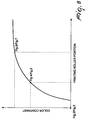
- the processing section 14 stores, for each movement of the printing plate roller 3, the position thereof and the contrast measured by the reader 7; the stored data can be represented as points of a Cartesian plane, where the X axis is the position of the printing plate roller 3 and the Y axis is the value of the contrast measured by the reader 7 (see the chart of Figure 8 ).
- the processing unit takes as a reference two points: the zero point, which is defined by the position of the printing roller and by the contrast measured by the reader 7, when no printing occurs; and the master point, which is defined by the position of the printing roller and by the contrast measured by the reader 7, when maximum printing pressure is applied.
- the reader 7 reads every millimeter of the printed material, along its entire width, and for each millimeter of printed material it sends to the processing section 14 a value that is representative of the ink cover of the print on the operator side of the machine and a value that is representative of the ink cover of the print on the transmission side of the machine.
- the processing section 14 stores the values of the ink cover for each millimeter of print, also known as "line cover", both for the operator side and for the transmission side.
- Each printing station involved in printing performs this step, one at a time.
- the processing section 14 analyzes and processes the acquired data, i.e., the zero point, the master point and the intermediate points defined by position and contrast, and calculates automatically the position and therefore the printing pressure of the printing plate roller 3 with respect to the central drum 2 in order to obtain the the desired print.
- the system takes as references the line cover of the master point of the operator side and the line cover of the master point on the transmission side.
- the system according to the invention calculates the position of the printing plate roller 3 with respect to the central drum 2 for the transmission side and for the operator side in order to achieve optimum printing as the position that has the maximum possible pressure reduction with respect to that of the master point without however causing a significant reduction in cover on any of the lines detected at the master point.
- the control section 15 orders the printing plate roller 3 to move to the positions calculated by the processing section 14 in order to achieve the desired print.
- the same method described above can also be performed to determine the correct printing pressures between the anilox roller 4 and the printing plate roller 3, by moving first the printing plate roller 3 to make contact with the material and then moving stepwise the anilox roller 4 from the position in which no contact occurs with the printing plate roller (condition of minimum contrast) to the position of maximum contact pressure (maximum contrast condition), until due to an increase of the printing pressure the contrast measured by the reader 7 no longer varies appreciably.
- the method for controlling printing pressures according to the invention therefore provides for analysis and processing of the data and calculation of the new positions only once, at the end of step 3, and not with each new positioning, as occurs in the background art.
- the advantage is a process which is simpler and faster and produces less printing waste.
- the reader 7 is arranged directly behind the print in output from the central drum 2 and before the drying oven.
- the materials used may be any according to requirements and to the state of the art.
Landscapes
- Engineering & Computer Science (AREA)
- Quality & Reliability (AREA)
- Mechanical Engineering (AREA)
- Rotary Presses (AREA)
- Inking, Control Or Cleaning Of Printing Machines (AREA)
- Printing Methods (AREA)
Description
- The present invention relates to a system and a method for monitoring the pressures of the printing rollers in a flexographic printing machine. More particularly, the invention relates to a system and a method for monitoring the pressures of the printing rollers in a flexographic printing machine upon starting a new job.
- As is known, flexographic printing machines with central drums have a plurality of printing plate rollers and anilox rollers arranged around a central drum; the printing plate rollers and anilox rollers transfer the ink onto the material to be printed depending on the printing pressures, i.e., depending on the pressure applied by each printing plate roller against the central drum and by each anilox roller against the respective printing plate. The pressure depends on the relative position of the printing plate with respect to the central drum and on the relative position of the anilox with respect to the printing plate.
- Job changing, which occurs whenever the elements that cooperate to perform the printing process change, which elements in flexographic printing are the printing plate, the printing plate double adhesive, the printing plate sleeve, the anilox, the material to be printed and the inks, as well as the variation in the environmental conditions, such as temperature and humidity, always requires, for obtaining the desired print, the identification of the correct printing pressures, i.e., of the correct relative positions between the printing plate and the drum and between the anilox and the printing plate with respect to those calculated by the machine on the basis of the theoretical dimensions of the printing elements.
- Identification of the correct pressures entails the production of product rejects and a waste of time and depends greatly on the skill and experience of the printer.
- Today there are already automatic systems that aid or replace the printer in identifying and applying the correct printing pressures at the beginning of the printing process after job changing.
- These systems can be divided substantially into two types: systems with print feedback; and offline systems without print feedback.
- The former substantially measures printed markings (the markings are representative marks of the print) or part of the printed image with a video camera and then corrects the printing pressures (see for example
EP 1249346 andEP 1666252 ). - The latter, substantially before printing, measures the surface dimensions of the printing plate roller with systems which are external to the machine, stores the measurement, then mounts the printing plate roller on the machine and positions it in contact with the central drum according to the stored data (see for example
US 2008/0141886 A1 ). - However, these systems have some problems.
- First of all, all systems with print feedback use a video camera that is capable of measuring and processing part of the printed image or more frequently specific markings that are representative of the printed image; the presence of these markings requires new printing plates and does not allow the use of old ones; moreover, each system uses different markings. The markings are located on the sides of the material and for an equal size of the printed image they require wider material and therefore a waste of material.
- Furthermore, all "online" systems with print feedback control the movement of the printing plate rollers and of the anilox rollers so as to vary the printing pressures, wait for the print to be read by the video camera, measure the effect of the motion of the printing plate rollers and anilox rollers on the print and resume this process until the pressures are found to be correct; this operation takes a long time and produces considerable waste, which increases as the distance of the video cameras from the printing of the colors increases, as generally occurs due to space occupation problems.
- All "online" systems with print feedback operate by comparing the print or the printed markings with a reference image that is representative of the print that one wishes to obtain in order to determine the correct printing pressures; the printer must therefore load this reference image into the system for example by means of a file.
- All offline systems without print feedback measure only the dimensions of the printing plate rollers and anilox rollers when they are not mounted on the machine; they do not measure the other elements that are responsible inside the machine for the printing pressures, i.e., the printing material, the inks, the tolerances and the mechanical plays; these and the relationships among them change after a change of job and can change over time with an effect on printing pressures.
- A further problem is that all offline systems without print feedback do not measure the print, are systems without feedback and therefore less precise and often require the intervention of the printer, who must retouch the printing pressures in order to obtain the desired print.
- Last but not least, all these systems are complicated and expensive, produce a considerable waste of product, require time for setting up the new job for printing and almost always require the intervention of the printer, who has to retouch the printing pressures in order to obtain the desired print.
- The aim of the present invention is to provide a system and a method for processing and monitoring printing pressures for a flexographic printing machine which solves the problems described above, i.e., a system and a method that measure directly the entire print and work with printing plates without markings and therefore do not require new printing plates.
- Within this aim, an object of the invention is to provide a system and a method that measure the print without using a video camera.
- Another object of the invention is to provide a system and a method that do not require the reference image for the printed image.
- Another object of the invention is to provide a system and a method that make it possible to reduce the waste of product and the time required for automatic setup of the printing pressures after a change of job.
- Another object of the invention is to provide a system and a method which are completely automatic and which, after completion of the method, do not require the intervention of the printer to retouch the printing pressures in order to obtain the desired print.
- Another object of the present invention is to provide a system and a method which are simpler, more reliable and cheaper than currently used systems.
- This aim, as well as these and other objects that will become more apparent hereinafter, are achieved by a system accoding to claim 1.
- Further characteristics and advantages of the invention will become more apparent from the description of a preferred but not exclusive embodiment of the system and of the method according to the invention, illustrated by way of non-limiting example in the accompanying drawings, wherein:
-
Figure 1 is a schematic view of a flexographic printing machine with central drum to which the system according to the invention is applied; -
Figures 2-3, 4-5 and 6-7 are views of three operating steps for the positioning of the printing rollers with respect to the central drum; -
Figure 8 is a chart which shows the contrast of the color in relation to the position of the printing roller. - With reference to the figures, a system according to the invention is applied to a printing machine and an assembly is generally designated by the
reference numeral 1. In particular, thereference numeral 2 designates a central drum of the printing machine, whereas thereference numerals 3 and 4 designate respectively pairs of printing rollers and anilox rollers which are arranged around thecentral drum 2 and conveniently can move on pairs ofguides anilox rollers 4 with respect to thecentral drum 2 of the flexographic printing machine. - Conventionally, the printing machine has an operator side, on which the printer works, and a transmission side, which is opposite to the operator side and on which the elements for transmission of the motion to the rollers of the machine are provided.
- The system described above further comprises at least one
reader 7, which is adapted to detect the contrast of the print on aprinting material 8, which depends on the contact pressure that the printing plate roller 3 exerts on the printedmaterial 8 wrapped around thecentral drum 2 and on the contact pressure that theanilox roller 4 exerts on the printing plate roller 3. - In particular, the
reader 7 reads the entire print and measures the contrast of the print of thematerial 8 with respect to the material without print. - More precisely, the
reader 7 is constituted by a scanning head whose size is equal to the width of theprinting material 8 and which comprises internally a plurality of independent modules composed of a linear sensor, an acquisition lens, a lighting portion, an electronic control system. The signal in output provided by thereader 7 is an integration of the acquisition area of such reader. - The
reader 7 is connected to a processing andcontrol unit 10, which is adapted to controlmotors 11 for the positioning of the printing plate rollers 3 andanilox rollers 4 with respect to thecentral drum 2. - The
reader 7 is synchronized with the printing performed by the printing rollers by means of a digital signal generated by avirtual printing plate 12. - The
virtual printing plate 12 is a motor which rotates so as to be synchronized with the printing plate rollers and is provided with an encoder which generates a digital signal at each turn, which thus represents the turn of the printing plate rollers. - Finally, a
control station 13 is used by the printer to control the operation of the system according to the invention. - The processing and
control unit 10 provides for aprocessing section 14 and acontrol section 15. - The method for controlling the printing pressures according to the invention comprises the following steps:
- From the
control station 13, the printer enters the data of the new job, such as for example the printing format, the type of material, the printing stations involved, the color printed by each station, and so forth. - The printer enables the process for controlling the printing pressures and commands the running of the printing machine. The printing machine accelerates to the speed at which the process for monitoring printing pressures occurs. The
drum printing roller 2, the printing plate roller 3 and theanilox roller 4 are not in contact and do not print. Thereader 7 performs self-calibration and measures the contrast of thematerial 8 without print. - The
control section 15 commands the printing rollers of the first station, among the ones that have been inserted, to make mutual contact in order to print; i.e., it commands the printing plate roller 3 to make contact with the material wrapped around thedrum 2 and theanilox roller 4 to make contact with the printing plate roller 3, according to a sequence of movements that are defined by a series of elevations calculated according to the dimensions of the rollers and of the printing systems. - The sequence first moves the
anilox roller 4 so as to make contact with the printing plate roller 3 and ink it, then moves stepwise, according to preset steps, the printing plate roller 3 from the position for not printing on the material (condition of minimum contrast) to the position of maximum printing pressure (condition of maximum contrast), until by an increase in printing pressure the contrast measured by thereader 7 no longer varies appreciably. - During the sequence, the
reader 7 reads and measures the contrast of thematerial 8, after each movement performed by the printing plate roller 3 in order to move from the non-printing position to the position of maximum printing pressure. The movement of the printing plate roller 3 and the reading process by thereader 7 are synchronized by thevirtual printing plate 12, for example every three turns of thevirtual printing plate 12; the reading of the first turn is rejected, since in the first turn there is the transition from printing determined by the old position to printing determined by the new position; the reading of the second turn is rejected because in the second turn the new print stabilizes, and the reading of the third turn is considered valid. - During the sequence, the
processing section 14 stores, for each movement of the printing plate roller 3, the position thereof and the contrast measured by thereader 7; the stored data can be represented as points of a Cartesian plane, where the X axis is the position of the printing plate roller 3 and the Y axis is the value of the contrast measured by the reader 7 (see the chart ofFigure 8 ). - Considering the chart of
Figure 8 , the processing unit takes as a reference two points: the zero point, which is defined by the position of the printing roller and by the contrast measured by thereader 7, when no printing occurs; and the master point, which is defined by the position of the printing roller and by the contrast measured by thereader 7, when maximum printing pressure is applied. - In particular, the
reader 7 reads every millimeter of the printed material, along its entire width, and for each millimeter of printed material it sends to the processing section 14 a value that is representative of the ink cover of the print on the operator side of the machine and a value that is representative of the ink cover of the print on the transmission side of the machine. - The
processing section 14 stores the values of the ink cover for each millimeter of print, also known as "line cover", both for the operator side and for the transmission side. - Each printing station involved in printing performs this step, one at a time.
- After this step, which is constituted by the positioning of the printing rollers and by the measurement of the contrast of the print as the positions in contact vary and therefore as the printing pressures of the rollers vary, the
processing section 14 analyzes and processes the acquired data, i.e., the zero point, the master point and the intermediate points defined by position and contrast, and calculates automatically the position and therefore the printing pressure of the printing plate roller 3 with respect to thecentral drum 2 in order to obtain the the desired print. - For each side of the print, the system takes as references the line cover of the master point of the operator side and the line cover of the master point on the transmission side.
- The system according to the invention calculates the position of the printing plate roller 3 with respect to the
central drum 2 for the transmission side and for the operator side in order to achieve optimum printing as the position that has the maximum possible pressure reduction with respect to that of the master point without however causing a significant reduction in cover on any of the lines detected at the master point. - As an alternative, it is possible to start from the zero point and detect the point when the degree of cover no longer increases.
- The
control section 15 orders the printing plate roller 3 to move to the positions calculated by theprocessing section 14 in order to achieve the desired print. - The same method described above can also be performed to determine the correct printing pressures between the
anilox roller 4 and the printing plate roller 3, by moving first the printing plate roller 3 to make contact with the material and then moving stepwise theanilox roller 4 from the position in which no contact occurs with the printing plate roller (condition of minimum contrast) to the position of maximum contact pressure (maximum contrast condition), until due to an increase of the printing pressure the contrast measured by thereader 7 no longer varies appreciably. - The method for controlling printing pressures according to the invention therefore provides for analysis and processing of the data and calculation of the new positions only once, at the end of step 3, and not with each new positioning, as occurs in the background art.
- The advantage is a process which is simpler and faster and produces less printing waste.
- For this purpose also, the
reader 7 is arranged directly behind the print in output from thecentral drum 2 and before the drying oven. - Also for this purpose, it is convenient for the method for controlling printing pressures according to the invention and in particular the sequence of predefined movements of the printing rollers to begin from the point where the printing plate roller 3 skims the
printing material 8 wrapped around thecentral drum 2 and theanilox roller 4 skims theprinting plate roller 4; this point is known as "kiss point". - In practice it has been found that the system and the method according to the invention fully achieve the intended aim and objects.
- The system and method thus conceived are susceptible of numerous modifications and variations, all of which are within the scope of the appended claims.
- In practice, the materials used, as well as the contingent shapes and dimensions, may be any according to requirements and to the state of the art.
- Where technical features mentioned in any claim are followed by reference signs, those reference signs have been included for the sole purpose of increasing the intelligibility of the claims and accordingly, such reference signs do not have any limiting effect on the interpretation of each element identified by way of example by such reference signs.
Claims (9)
- A system for adjusting and monitoring the pressures of printing rollers (3, 4) of printing stations arranged around a central drum (2) of a flexographic printing machine, comprising:at least one reader (7) which is adapted to be placed at the printing rollers (3, 4) of the printing machine directly behind the print in output from the central drum (2) to detect the contrast of the print on the printing material (8) wrapped around the central dram (2) of the printing machine, said reader (7) is constituted by a scanning head whose size is equal to the width of the printing material (8), and said reader (7) is capable of reading over the entire printing width and of directly measuring the amount of the entire print on the printing material (8) with respect to its background, said amount corresponding to said contrast; anda processing and control unit (10) which is connected to said at least one reader (7) and is adapted to determine and control, as a function of the contrast detected by said reader (7), the position of the printing rollers (3, 4) with respect to said central drum (2) in order to achieve the desired print; andwherein said processing and control unit (10) comprises a control section (15) and a processing section (14) that are adapted:to command performance of a sequence of stepwise movements, according to preset steps, of the printing plate roller (3) with respect to the central drum (2) or also of the anilox roller (4) with respect to the printing plate roller (3), in order to make contact in printing at different printing pressures,to store for each movement of the printing plate roller (3) data acquired regarding its position and the contrast measured by the reader (7); andto analyse and elaborate the acquired data and automatically calculate, the position and therefore the printing pressure of the printing plate roller (3) with respect to the central drum (2) in order to achieve the desired print.
- The system according to claim 1, characterized in that it comprises a virtual printing plate (12) for synchronizing the movement of the printing plate rollers (3) and the reading by the at least one reader (7) which is connected to said processing and control unit (10).
- The system according to claim 2, characterized in that said virtual printing plate (12) is constituted by a motor which rotates so as to be synchronized with the printing plate rollers (3) and is provided with an encoder which generates a digital signal at each turn, which thus represents the turn of the printing plate rollers (3).
- The system according to claims 2 or 3, characterized in that said virtual printing plate (12) is synchronous with all the printing rollers (3, 4) of the flexographic printing machine.
- The system according to one or more of the preceding claims, characterized in that said processing and control unit (10) controls the movement of the printing plate roller (3) with respect to the central drum (2) and the movement of the anilox roller (4) with respect to the printing plate roller (3).
- A method for controlling printing pressures for a flexographic printing machine by means of a system according to one or more of the preceding claims, characterized in that it comprises the following steps:1) entering from the control station the data of the new job, such as for example the printing format, the type of material to be printed, the printing stations involved, the color that is present on each station;2) making the machine run at the speed at which the method for controlling printing pressures is performed and measuring the contrast of the printing material (8) without printing by means of the at least one reader (7);3) performing a sequence of stepwise movements of the printing plate roller (3) with respect to the central drum (2) or also of the anilox roller (4) with respect to the printing plate roller (3), in order to make contact in printing at different printing pressures, and measuring the contrast of the print by means of the reader (7) and during performance of said sequence, storing for each movement of the printing plate roller (3) data acquired regarding its position and the contrast measured by the reader (7);4) at the end of the sequence of movements and of the corresponding contrast measurements, analyzing and elaborating the acquired data and automatically calculating, the position and therefore the printing pressure of the printing plate roller (3) with respect to the central drum (2) in order to achieve the desired print.
- The method according to claim 6, characterized in that the step of moving said printing rollers (3, 4) with respect to said central drum (2) is performed starting from a zero point or kiss point, assumed as the point at which the printing plate roller (3) skims the printing material (8) or the anilox roller (4) skims the printing plate roller (3).
- The method according to claim 7, characterized in that the movement of the printing plate roller (3) with respect to the central drum (2) and of the anilox roller (4) with respect to the printing plate roller (3) is performed with a sequence of movements with preset spacings, defined by elevations with respect to said zero point or kiss point.
- The method according to claims 7 or 8, characterized in that said zero point or kiss point is the point where said printing plate roller (3) begins to make contact with said printing material (8) arranged on said central drum (2) or the point where said anilox roller (4) begins to make contact with said printing plate roller (3).
Applications Claiming Priority (2)
| Application Number | Priority Date | Filing Date | Title |
|---|---|---|---|
| ITVR2010A000252A IT1403496B1 (en) | 2010-12-27 | 2010-12-27 | SYSTEM AND PROCEDURE FOR SETTING AND CHECKING THE PRESSURES OF PRINTING CYLINDERS IN A FLEXOGRAPHIC PRINTING MACHINE WITH CENTRAL DRUM |
| PCT/EP2011/072621 WO2012089496A1 (en) | 2010-12-27 | 2011-12-13 | System and method for adjusting and monitoring the pressures of printing rollers in a flexographic printing machine with central drum |
Publications (2)
| Publication Number | Publication Date |
|---|---|
| EP2658717A1 EP2658717A1 (en) | 2013-11-06 |
| EP2658717B1 true EP2658717B1 (en) | 2016-03-02 |
Family
ID=43737586
Family Applications (1)
| Application Number | Title | Priority Date | Filing Date |
|---|---|---|---|
| EP11793840.7A Active EP2658717B1 (en) | 2010-12-27 | 2011-12-13 | System and method for adjusting and monitoring the pressures of printing rollers in a flexographic printing machine with central drum |
Country Status (11)
| Country | Link |
|---|---|
| US (1) | US9259914B2 (en) |
| EP (1) | EP2658717B1 (en) |
| CN (1) | CN103547453B (en) |
| AR (1) | AR084512A1 (en) |
| AU (1) | AU2011351704B2 (en) |
| BR (1) | BR112013016496A2 (en) |
| CA (1) | CA2823059C (en) |
| ES (1) | ES2574492T3 (en) |
| IT (1) | IT1403496B1 (en) |
| RU (1) | RU2587788C2 (en) |
| WO (1) | WO2012089496A1 (en) |
Families Citing this family (12)
| Publication number | Priority date | Publication date | Assignee | Title |
|---|---|---|---|---|
| EP2711186A3 (en) * | 2012-09-19 | 2014-05-21 | BST International GmbH | Method and device for adjusting printing units relative to a printing cylinder |
| ITVR20130064A1 (en) * | 2013-03-12 | 2014-09-13 | Expert S R L | METHOD OF POSITIONING THE CYLINDERS OF A PRINTING GROUP IN A FLEXOGRAPHIC OR ROTARY PRINTING MACHINE |
| EP2818319B1 (en) * | 2013-06-28 | 2015-08-05 | CONPRINTA GmbH & Co. KG | Printer |
| JP6307267B2 (en) * | 2013-12-25 | 2018-04-04 | アイマー・プランニング株式会社 | Printer |
| DE102016215748A1 (en) | 2016-08-23 | 2018-03-01 | Robert Bosch Gmbh | Flexographic printing machine with different peripheral speeds on the anilox roller and the plate cylinder |
| EP3526046B1 (en) * | 2016-09-13 | 2026-04-15 | Advanced Vision Technology (AVT) Ltd. | System and method for controlling color characteristics of a printed image |
| CN109760407A (en) * | 2019-03-09 | 2019-05-17 | 深圳市正鑫源实业有限公司 | The control method and its letterpress system of intelligent letterpress force of impression |
| EP4000931B2 (en) | 2019-05-09 | 2025-12-31 | Heidelberger Druckmaschinen AG | DEVICE FOR MEASURING SURFACE EDGES OF A ROTATING BODY |
| CN110936743B (en) * | 2019-11-29 | 2021-09-10 | 西安理工大学 | Flexographic printing pressure prediction method based on image-text information |
| DK3988314T3 (en) * | 2020-10-22 | 2024-08-26 | Heidelberger Druckmasch Ag | APPARATUS FOR MEASURING A SURFACE OR ITS ELEVATIONS ON A BODY OF REVOLUTION AND SYSTEM |
| DE102021125336A1 (en) * | 2020-10-22 | 2022-04-28 | Heidelberger Druckmaschinen Aktiengesellschaft | Device for measuring elevations on the surface of a body of revolution and system |
| CN118329197B (en) * | 2024-06-17 | 2024-08-27 | 滕州运城制版有限公司 | Abnormality monitoring method and system for printing plate roller |
Citations (5)
| Publication number | Priority date | Publication date | Assignee | Title |
|---|---|---|---|---|
| US4667596A (en) | 1982-03-16 | 1987-05-26 | Windmoller & Holscher | Method of automatically setting the colors printed out by flexographic printing machines for four-color printing |
| WO2004065127A2 (en) | 2003-01-24 | 2004-08-05 | Windmöller & Hölscher Kg | Method for the correction of variations in the amount of ink applied to the printed image occurring in the printing process |
| EP1666252A2 (en) | 2001-03-27 | 2006-06-07 | Windmöller & Hölscher KG | Device and method for adjusting the printing image in a flexographic printing machine |
| WO2007086052A2 (en) | 2006-01-25 | 2007-08-02 | Advanced Vision Technology (Avt) Ltd. | System and method for setting up a printing press |
| EP1843898B1 (en) | 2005-02-03 | 2008-07-30 | Windmöller & Hölscher KG | Registering method |
Family Cites Families (15)
| Publication number | Priority date | Publication date | Assignee | Title |
|---|---|---|---|---|
| DE3331738A1 (en) | 1983-09-02 | 1985-03-21 | Wabco Westinghouse Fahrzeugbremsen GmbH, 3000 Hannover | ACTUATOR |
| WO1995000337A1 (en) * | 1993-06-17 | 1995-01-05 | The Analytic Sciences Corporation | Automated system for print quality control |
| US5774225A (en) * | 1996-03-27 | 1998-06-30 | Advanced Vision Technology, Ltd. | System and method for color measurement and control on-press during printing |
| US5731989A (en) * | 1996-04-25 | 1998-03-24 | Advance Vision Technology (A.V.T.) Ltd. | Method and device for determining a measurement for color control in a printing process |
| IT1299666B1 (en) | 1998-05-05 | 2000-03-24 | Uteco Spa Roto Flexo & Convert | MULTI-COLOR CENTRAL DRUM FLEXOGRAPHIC ROTARY MACHINE |
| US20060219109A1 (en) * | 2003-03-20 | 2006-10-05 | Cadillach Felip F | Method of registering different colours in flexography, and flexographic printer comprising a device for implementing said method |
| DE102004021601B4 (en) * | 2004-05-03 | 2020-10-22 | Heidelberger Druckmaschinen Ag | Inline measurement and control for printing machines |
| DE102005013360B4 (en) * | 2005-03-23 | 2018-09-13 | Manroland Web Systems Gmbh | Method for positioning printing plates on cylinders of a printing machine |
| DE102005054122B4 (en) * | 2005-11-12 | 2017-09-21 | manroland sheetfed GmbH | Method for operating a quality control system for a sheet-fed rotary printing press |
| WO2008041986A1 (en) * | 2006-10-05 | 2008-04-10 | Hewlett-Packard Development Company, L.P. | Automatic adjustment of printer drum spacing |
| DE602006012688D1 (en) | 2006-10-23 | 2010-04-15 | Fischer & Krecke Gmbh | Method, Monatagevorrichtung and control unit for adjusting a roller in a printing press |
| JP2008212826A (en) * | 2007-03-05 | 2008-09-18 | Komori Corp | Method for adjusting contact pressure of liquid application machine and contact pressure adjustment device for liquid application machine |
| DE102007022079A1 (en) * | 2007-05-11 | 2008-11-13 | Heidelberger Druckmaschinen Ag | Method for automated adjustment of a rotational body pressure in a printing machine |
| JP2009000881A (en) * | 2007-06-21 | 2009-01-08 | Komori Corp | Printing quality control method and apparatus for relief printing press |
| ITFI20080064A1 (en) * | 2008-04-04 | 2009-10-05 | Perini Fabio Spa | "PRINTING MACHINE AND METHOD FOR ITS CALIBRATION" |
-
2010
- 2010-12-27 IT ITVR2010A000252A patent/IT1403496B1/en active
-
2011
- 2011-12-13 AU AU2011351704A patent/AU2011351704B2/en not_active Ceased
- 2011-12-13 CN CN201180062974.7A patent/CN103547453B/en not_active Expired - Fee Related
- 2011-12-13 US US13/976,753 patent/US9259914B2/en active Active
- 2011-12-13 EP EP11793840.7A patent/EP2658717B1/en active Active
- 2011-12-13 RU RU2013135293/12A patent/RU2587788C2/en active
- 2011-12-13 BR BR112013016496A patent/BR112013016496A2/en not_active Application Discontinuation
- 2011-12-13 WO PCT/EP2011/072621 patent/WO2012089496A1/en not_active Ceased
- 2011-12-13 ES ES11793840.7T patent/ES2574492T3/en active Active
- 2011-12-13 CA CA2823059A patent/CA2823059C/en active Active
- 2011-12-21 AR ARP110104851A patent/AR084512A1/en not_active Application Discontinuation
Patent Citations (5)
| Publication number | Priority date | Publication date | Assignee | Title |
|---|---|---|---|---|
| US4667596A (en) | 1982-03-16 | 1987-05-26 | Windmoller & Holscher | Method of automatically setting the colors printed out by flexographic printing machines for four-color printing |
| EP1666252A2 (en) | 2001-03-27 | 2006-06-07 | Windmöller & Hölscher KG | Device and method for adjusting the printing image in a flexographic printing machine |
| WO2004065127A2 (en) | 2003-01-24 | 2004-08-05 | Windmöller & Hölscher Kg | Method for the correction of variations in the amount of ink applied to the printed image occurring in the printing process |
| EP1843898B1 (en) | 2005-02-03 | 2008-07-30 | Windmöller & Hölscher KG | Registering method |
| WO2007086052A2 (en) | 2006-01-25 | 2007-08-02 | Advanced Vision Technology (Avt) Ltd. | System and method for setting up a printing press |
Also Published As
| Publication number | Publication date |
|---|---|
| RU2587788C2 (en) | 2016-06-20 |
| IT1403496B1 (en) | 2013-10-17 |
| ITVR20100252A1 (en) | 2012-06-28 |
| AU2011351704A1 (en) | 2013-07-11 |
| CA2823059C (en) | 2019-02-12 |
| WO2012089496A1 (en) | 2012-07-05 |
| AU2011351704B2 (en) | 2015-08-20 |
| AR084512A1 (en) | 2013-05-22 |
| ES2574492T3 (en) | 2016-06-20 |
| RU2013135293A (en) | 2015-02-10 |
| BR112013016496A2 (en) | 2016-09-27 |
| US9259914B2 (en) | 2016-02-16 |
| CN103547453A (en) | 2014-01-29 |
| CN103547453B (en) | 2015-12-16 |
| CA2823059A1 (en) | 2012-07-05 |
| US20130269560A1 (en) | 2013-10-17 |
| EP2658717A1 (en) | 2013-11-06 |
Similar Documents
| Publication | Publication Date | Title |
|---|---|---|
| CA2823059C (en) | System and method for adjusting and monitoring the pressures of printing rollers in a flexographic printing machine with central drum | |
| CN111907211B (en) | Apparatus for measuring the elevation of the surface of a rotating body | |
| US8534194B2 (en) | Rotary printing press and method for adjusting a cylinder thereof | |
| US20160318297A1 (en) | Method of adjusting a roller in a rotary printing press | |
| CN110978777B (en) | Method for automatically printing and registering colors by using printing roller without automatic registering and marking | |
| US9010242B2 (en) | Method and device for controlling the register settings of a printing press | |
| CN114379221B (en) | Device for measuring the ridges on the surface of a rotating body | |
| US20220126563A1 (en) | Method of operating a flexographic printing press, flexographic printing press, system, and sleeve for a flexographic printing forme | |
| US11865830B2 (en) | Method of operating a flexographic printing press, flexographic printing press, system and sleeve | |
| US20100011978A1 (en) | Rotary Printing Press and Method for Adjusting a Cylinder Thereof | |
| US11752756B2 (en) | Method of operating a flexographic printing press, and system | |
| US20110267637A1 (en) | Automatic register control system with intelligent optical sensor and dry presetting facility | |
| CN114379219B (en) | Flexographic printing machine, method and system for operating same, flexographic stamp and sleeve | |
| US20090283002A1 (en) | Method for printing correction | |
| US20100139512A1 (en) | Method and apparatus for regulating the register in a printing press | |
| CN114379220B (en) | Device and system for measuring the ridges on the surface of a rotating body | |
| KR20190099496A (en) | Control device and inspection device | |
| US6880458B2 (en) | Process and device for determining the position and/or the shape of marks on printed-on paper webs | |
| US20070051265A1 (en) | Method for printing correction | |
| EP2675623B1 (en) | Method and device for the control and management of the printing parameters of a printing machine, particularly with a plurality of consecutive printing processes | |
| US20130340641A1 (en) | Methods and systems for setting the pressure of the cylinders of the printing press without requiring special targets | |
| WO2011142943A2 (en) | An autofocus imaging apparatus | |
| US20080196610A1 (en) | Adjusting device and method for rotary printing machine | |
| US9242453B2 (en) | Method for compensating deflection of an ink fountain in printing presses | |
| CN119887640A (en) | RFID aluminum foil front and back color register control method and system |
Legal Events
| Date | Code | Title | Description |
|---|---|---|---|
| PUAI | Public reference made under article 153(3) epc to a published international application that has entered the european phase |
Free format text: ORIGINAL CODE: 0009012 |
|
| 17P | Request for examination filed |
Effective date: 20130619 |
|
| AK | Designated contracting states |
Kind code of ref document: A1 Designated state(s): AL AT BE BG CH CY CZ DE DK EE ES FI FR GB GR HR HU IE IS IT LI LT LU LV MC MK MT NL NO PL PT RO RS SE SI SK SM TR |
|
| RIN1 | Information on inventor provided before grant (corrected) |
Inventor name: DE GRANDIS, PAOLO Inventor name: PERETTI, ALDO Inventor name: RESENTERA, MASSIMO Inventor name: FILIPPI, DAVIDE ANDREA MARIA Inventor name: CATTARUZZA, MAURO Inventor name: ARTUFFO, LUIGI |
|
| DAX | Request for extension of the european patent (deleted) | ||
| GRAP | Despatch of communication of intention to grant a patent |
Free format text: ORIGINAL CODE: EPIDOSNIGR1 |
|
| INTG | Intention to grant announced |
Effective date: 20141125 |
|
| GRAS | Grant fee paid |
Free format text: ORIGINAL CODE: EPIDOSNIGR3 |
|
| GRAP | Despatch of communication of intention to grant a patent |
Free format text: ORIGINAL CODE: EPIDOSNIGR1 |
|
| GRAJ | Information related to disapproval of communication of intention to grant by the applicant or resumption of examination proceedings by the epo deleted |
Free format text: ORIGINAL CODE: EPIDOSDIGR1 |
|
| GRAP | Despatch of communication of intention to grant a patent |
Free format text: ORIGINAL CODE: EPIDOSNIGR1 |
|
| INTG | Intention to grant announced |
Effective date: 20150729 |
|
| INTG | Intention to grant announced |
Effective date: 20150812 |
|
| GRAA | (expected) grant |
Free format text: ORIGINAL CODE: 0009210 |
|
| AK | Designated contracting states |
Kind code of ref document: B1 Designated state(s): AL AT BE BG CH CY CZ DE DK EE ES FI FR GB GR HR HU IE IS IT LI LT LU LV MC MK MT NL NO PL PT RO RS SE SI SK SM TR |
|
| REG | Reference to a national code |
Ref country code: GB Ref legal event code: FG4D |
|
| REG | Reference to a national code |
Ref country code: AT Ref legal event code: REF Ref document number: 777723 Country of ref document: AT Kind code of ref document: T Effective date: 20160315 Ref country code: CH Ref legal event code: EP |
|
| REG | Reference to a national code |
Ref country code: IE Ref legal event code: FG4D |
|
| REG | Reference to a national code |
Ref country code: DE Ref legal event code: R096 Ref document number: 602011023681 Country of ref document: DE |
|
| REG | Reference to a national code |
Ref country code: CH Ref legal event code: NV Representative=s name: MODIANO AND PARTNERS SA, CH |
|
| REG | Reference to a national code |
Ref country code: ES Ref legal event code: FG2A Ref document number: 2574492 Country of ref document: ES Kind code of ref document: T3 Effective date: 20160620 |
|
| REG | Reference to a national code |
Ref country code: NL Ref legal event code: MP Effective date: 20160302 |
|
| REG | Reference to a national code |
Ref country code: LT Ref legal event code: MG4D |
|
| REG | Reference to a national code |
Ref country code: AT Ref legal event code: MK05 Ref document number: 777723 Country of ref document: AT Kind code of ref document: T Effective date: 20160302 |
|
| PG25 | Lapsed in a contracting state [announced via postgrant information from national office to epo] |
Ref country code: GR Free format text: LAPSE BECAUSE OF FAILURE TO SUBMIT A TRANSLATION OF THE DESCRIPTION OR TO PAY THE FEE WITHIN THE PRESCRIBED TIME-LIMIT Effective date: 20160603 Ref country code: NO Free format text: LAPSE BECAUSE OF FAILURE TO SUBMIT A TRANSLATION OF THE DESCRIPTION OR TO PAY THE FEE WITHIN THE PRESCRIBED TIME-LIMIT Effective date: 20160602 Ref country code: FI Free format text: LAPSE BECAUSE OF FAILURE TO SUBMIT A TRANSLATION OF THE DESCRIPTION OR TO PAY THE FEE WITHIN THE PRESCRIBED TIME-LIMIT Effective date: 20160302 Ref country code: HR Free format text: LAPSE BECAUSE OF FAILURE TO SUBMIT A TRANSLATION OF THE DESCRIPTION OR TO PAY THE FEE WITHIN THE PRESCRIBED TIME-LIMIT Effective date: 20160302 |
|
| PG25 | Lapsed in a contracting state [announced via postgrant information from national office to epo] |
Ref country code: LT Free format text: LAPSE BECAUSE OF FAILURE TO SUBMIT A TRANSLATION OF THE DESCRIPTION OR TO PAY THE FEE WITHIN THE PRESCRIBED TIME-LIMIT Effective date: 20160302 Ref country code: PL Free format text: LAPSE BECAUSE OF FAILURE TO SUBMIT A TRANSLATION OF THE DESCRIPTION OR TO PAY THE FEE WITHIN THE PRESCRIBED TIME-LIMIT Effective date: 20160302 Ref country code: AT Free format text: LAPSE BECAUSE OF FAILURE TO SUBMIT A TRANSLATION OF THE DESCRIPTION OR TO PAY THE FEE WITHIN THE PRESCRIBED TIME-LIMIT Effective date: 20160302 Ref country code: LV Free format text: LAPSE BECAUSE OF FAILURE TO SUBMIT A TRANSLATION OF THE DESCRIPTION OR TO PAY THE FEE WITHIN THE PRESCRIBED TIME-LIMIT Effective date: 20160302 Ref country code: NL Free format text: LAPSE BECAUSE OF FAILURE TO SUBMIT A TRANSLATION OF THE DESCRIPTION OR TO PAY THE FEE WITHIN THE PRESCRIBED TIME-LIMIT Effective date: 20160302 Ref country code: RS Free format text: LAPSE BECAUSE OF FAILURE TO SUBMIT A TRANSLATION OF THE DESCRIPTION OR TO PAY THE FEE WITHIN THE PRESCRIBED TIME-LIMIT Effective date: 20160302 Ref country code: SE Free format text: LAPSE BECAUSE OF FAILURE TO SUBMIT A TRANSLATION OF THE DESCRIPTION OR TO PAY THE FEE WITHIN THE PRESCRIBED TIME-LIMIT Effective date: 20160302 |
|
| PG25 | Lapsed in a contracting state [announced via postgrant information from national office to epo] |
Ref country code: EE Free format text: LAPSE BECAUSE OF FAILURE TO SUBMIT A TRANSLATION OF THE DESCRIPTION OR TO PAY THE FEE WITHIN THE PRESCRIBED TIME-LIMIT Effective date: 20160302 Ref country code: IS Free format text: LAPSE BECAUSE OF FAILURE TO SUBMIT A TRANSLATION OF THE DESCRIPTION OR TO PAY THE FEE WITHIN THE PRESCRIBED TIME-LIMIT Effective date: 20160702 |
|
| REG | Reference to a national code |
Ref country code: FR Ref legal event code: PLFP Year of fee payment: 6 |
|
| PG25 | Lapsed in a contracting state [announced via postgrant information from national office to epo] |
Ref country code: SM Free format text: LAPSE BECAUSE OF FAILURE TO SUBMIT A TRANSLATION OF THE DESCRIPTION OR TO PAY THE FEE WITHIN THE PRESCRIBED TIME-LIMIT Effective date: 20160302 Ref country code: RO Free format text: LAPSE BECAUSE OF FAILURE TO SUBMIT A TRANSLATION OF THE DESCRIPTION OR TO PAY THE FEE WITHIN THE PRESCRIBED TIME-LIMIT Effective date: 20160302 Ref country code: PT Free format text: LAPSE BECAUSE OF FAILURE TO SUBMIT A TRANSLATION OF THE DESCRIPTION OR TO PAY THE FEE WITHIN THE PRESCRIBED TIME-LIMIT Effective date: 20160704 Ref country code: SK Free format text: LAPSE BECAUSE OF FAILURE TO SUBMIT A TRANSLATION OF THE DESCRIPTION OR TO PAY THE FEE WITHIN THE PRESCRIBED TIME-LIMIT Effective date: 20160302 |
|
| REG | Reference to a national code |
Ref country code: DE Ref legal event code: R026 Ref document number: 602011023681 Country of ref document: DE |
|
| PLBI | Opposition filed |
Free format text: ORIGINAL CODE: 0009260 |
|
| PG25 | Lapsed in a contracting state [announced via postgrant information from national office to epo] |
Ref country code: BE Free format text: LAPSE BECAUSE OF FAILURE TO SUBMIT A TRANSLATION OF THE DESCRIPTION OR TO PAY THE FEE WITHIN THE PRESCRIBED TIME-LIMIT Effective date: 20160302 |
|
| 26 | Opposition filed |
Opponent name: WINDMOELLER & HOELSCHER KG Effective date: 20161202 |
|
| PLAX | Notice of opposition and request to file observation + time limit sent |
Free format text: ORIGINAL CODE: EPIDOSNOBS2 |
|
| PG25 | Lapsed in a contracting state [announced via postgrant information from national office to epo] |
Ref country code: DK Free format text: LAPSE BECAUSE OF FAILURE TO SUBMIT A TRANSLATION OF THE DESCRIPTION OR TO PAY THE FEE WITHIN THE PRESCRIBED TIME-LIMIT Effective date: 20160302 |
|
| PG25 | Lapsed in a contracting state [announced via postgrant information from national office to epo] |
Ref country code: BG Free format text: LAPSE BECAUSE OF FAILURE TO SUBMIT A TRANSLATION OF THE DESCRIPTION OR TO PAY THE FEE WITHIN THE PRESCRIBED TIME-LIMIT Effective date: 20160602 Ref country code: SI Free format text: LAPSE BECAUSE OF FAILURE TO SUBMIT A TRANSLATION OF THE DESCRIPTION OR TO PAY THE FEE WITHIN THE PRESCRIBED TIME-LIMIT Effective date: 20160302 |
|
| PLBB | Reply of patent proprietor to notice(s) of opposition received |
Free format text: ORIGINAL CODE: EPIDOSNOBS3 |
|
| PG25 | Lapsed in a contracting state [announced via postgrant information from national office to epo] |
Ref country code: MC Free format text: LAPSE BECAUSE OF FAILURE TO SUBMIT A TRANSLATION OF THE DESCRIPTION OR TO PAY THE FEE WITHIN THE PRESCRIBED TIME-LIMIT Effective date: 20160302 |
|
| REG | Reference to a national code |
Ref country code: IE Ref legal event code: MM4A |
|
| PG25 | Lapsed in a contracting state [announced via postgrant information from national office to epo] |
Ref country code: LU Free format text: LAPSE BECAUSE OF NON-PAYMENT OF DUE FEES Effective date: 20161213 |
|
| PG25 | Lapsed in a contracting state [announced via postgrant information from national office to epo] |
Ref country code: IE Free format text: LAPSE BECAUSE OF NON-PAYMENT OF DUE FEES Effective date: 20161213 |
|
| REG | Reference to a national code |
Ref country code: FR Ref legal event code: PLFP Year of fee payment: 7 |
|
| PG25 | Lapsed in a contracting state [announced via postgrant information from national office to epo] |
Ref country code: HU Free format text: LAPSE BECAUSE OF FAILURE TO SUBMIT A TRANSLATION OF THE DESCRIPTION OR TO PAY THE FEE WITHIN THE PRESCRIBED TIME-LIMIT; INVALID AB INITIO Effective date: 20111213 Ref country code: CY Free format text: LAPSE BECAUSE OF FAILURE TO SUBMIT A TRANSLATION OF THE DESCRIPTION OR TO PAY THE FEE WITHIN THE PRESCRIBED TIME-LIMIT Effective date: 20160302 |
|
| PG25 | Lapsed in a contracting state [announced via postgrant information from national office to epo] |
Ref country code: MK Free format text: LAPSE BECAUSE OF FAILURE TO SUBMIT A TRANSLATION OF THE DESCRIPTION OR TO PAY THE FEE WITHIN THE PRESCRIBED TIME-LIMIT Effective date: 20160302 |
|
| REG | Reference to a national code |
Ref country code: CH Ref legal event code: PCAR Free format text: NEW ADDRESS: VIA E. BOSSI 1, 6900 LUGANO (CH) |
|
| REG | Reference to a national code |
Ref country code: FR Ref legal event code: PLFP Year of fee payment: 8 |
|
| PG25 | Lapsed in a contracting state [announced via postgrant information from national office to epo] |
Ref country code: MT Free format text: LAPSE BECAUSE OF NON-PAYMENT OF DUE FEES Effective date: 20161213 |
|
| PG25 | Lapsed in a contracting state [announced via postgrant information from national office to epo] |
Ref country code: AL Free format text: LAPSE BECAUSE OF FAILURE TO SUBMIT A TRANSLATION OF THE DESCRIPTION OR TO PAY THE FEE WITHIN THE PRESCRIBED TIME-LIMIT Effective date: 20160302 Ref country code: TR Free format text: LAPSE BECAUSE OF FAILURE TO SUBMIT A TRANSLATION OF THE DESCRIPTION OR TO PAY THE FEE WITHIN THE PRESCRIBED TIME-LIMIT Effective date: 20160302 |
|
| APBM | Appeal reference recorded |
Free format text: ORIGINAL CODE: EPIDOSNREFNO |
|
| APBP | Date of receipt of notice of appeal recorded |
Free format text: ORIGINAL CODE: EPIDOSNNOA2O |
|
| APAH | Appeal reference modified |
Free format text: ORIGINAL CODE: EPIDOSCREFNO |
|
| APBM | Appeal reference recorded |
Free format text: ORIGINAL CODE: EPIDOSNREFNO |
|
| APBP | Date of receipt of notice of appeal recorded |
Free format text: ORIGINAL CODE: EPIDOSNNOA2O |
|
| P01 | Opt-out of the competence of the unified patent court (upc) registered |
Effective date: 20230529 |
|
| REG | Reference to a national code |
Ref country code: DE Ref legal event code: R100 Ref document number: 602011023681 Country of ref document: DE |
|
| APBU | Appeal procedure closed |
Free format text: ORIGINAL CODE: EPIDOSNNOA9O |
|
| PLBN | Opposition rejected |
Free format text: ORIGINAL CODE: 0009273 |
|
| PLCK | Communication despatched that opposition was rejected |
Free format text: ORIGINAL CODE: EPIDOSNREJ1 |
|
| STAA | Information on the status of an ep patent application or granted ep patent |
Free format text: STATUS: OPPOSITION REJECTED |
|
| 27O | Opposition rejected |
Effective date: 20230927 |
|
| PGFP | Annual fee paid to national office [announced via postgrant information from national office to epo] |
Ref country code: GB Payment date: 20231206 Year of fee payment: 13 |
|
| PGFP | Annual fee paid to national office [announced via postgrant information from national office to epo] |
Ref country code: IT Payment date: 20231218 Year of fee payment: 13 Ref country code: FR Payment date: 20231211 Year of fee payment: 13 Ref country code: DE Payment date: 20231218 Year of fee payment: 13 Ref country code: CZ Payment date: 20231130 Year of fee payment: 13 |
|
| PGFP | Annual fee paid to national office [announced via postgrant information from national office to epo] |
Ref country code: ES Payment date: 20240104 Year of fee payment: 13 |
|
| PGFP | Annual fee paid to national office [announced via postgrant information from national office to epo] |
Ref country code: CH Payment date: 20240101 Year of fee payment: 13 |
|
| REG | Reference to a national code |
Ref country code: DE Ref legal event code: R119 Ref document number: 602011023681 Country of ref document: DE |
|
| PG25 | Lapsed in a contracting state [announced via postgrant information from national office to epo] |
Ref country code: CZ Free format text: LAPSE BECAUSE OF NON-PAYMENT OF DUE FEES Effective date: 20241213 |
|
| REG | Reference to a national code |
Ref country code: CH Ref legal event code: PL |
|
| GBPC | Gb: european patent ceased through non-payment of renewal fee |
Effective date: 20241213 |
|
| PG25 | Lapsed in a contracting state [announced via postgrant information from national office to epo] |
Ref country code: DE Free format text: LAPSE BECAUSE OF NON-PAYMENT OF DUE FEES Effective date: 20250701 |
|
| PG25 | Lapsed in a contracting state [announced via postgrant information from national office to epo] |
Ref country code: IT Free format text: LAPSE BECAUSE OF NON-PAYMENT OF DUE FEES Effective date: 20241213 |
|
| PG25 | Lapsed in a contracting state [announced via postgrant information from national office to epo] |
Ref country code: GB Free format text: LAPSE BECAUSE OF NON-PAYMENT OF DUE FEES Effective date: 20241213 |
|
| PG25 | Lapsed in a contracting state [announced via postgrant information from national office to epo] |
Ref country code: FR Free format text: LAPSE BECAUSE OF NON-PAYMENT OF DUE FEES Effective date: 20241231 |
|
| PG25 | Lapsed in a contracting state [announced via postgrant information from national office to epo] |
Ref country code: CH Free format text: LAPSE BECAUSE OF NON-PAYMENT OF DUE FEES Effective date: 20241231 |
|
| REG | Reference to a national code |
Ref country code: ES Ref legal event code: FD2A Effective date: 20260129 |
|
| PG25 | Lapsed in a contracting state [announced via postgrant information from national office to epo] |
Ref country code: ES Free format text: LAPSE BECAUSE OF NON-PAYMENT OF DUE FEES Effective date: 20241214 |