EP2658368B1 - Fischpark mit mittigem holm und verfahren zur fischbegrenzung im freiwasser - Google Patents
Fischpark mit mittigem holm und verfahren zur fischbegrenzung im freiwasser Download PDFInfo
- Publication number
- EP2658368B1 EP2658368B1 EP11853125.0A EP11853125A EP2658368B1 EP 2658368 B1 EP2658368 B1 EP 2658368B1 EP 11853125 A EP11853125 A EP 11853125A EP 2658368 B1 EP2658368 B1 EP 2658368B1
- Authority
- EP
- European Patent Office
- Prior art keywords
- fish
- assembly
- attached
- fish pen
- spar buoy
- Prior art date
- Legal status (The legal status is an assumption and is not a legal conclusion. Google has not performed a legal analysis and makes no representation as to the accuracy of the status listed.)
- Active
Links
- 241000251468 Actinopterygii Species 0.000 title claims description 139
- XLYOFNOQVPJJNP-UHFFFAOYSA-N water Substances O XLYOFNOQVPJJNP-UHFFFAOYSA-N 0.000 title claims description 16
- 238000000034 method Methods 0.000 title claims description 4
- 230000000712 assembly Effects 0.000 claims description 29
- 238000000429 assembly Methods 0.000 claims description 29
- 238000003032 molecular docking Methods 0.000 claims description 12
- 239000000463 material Substances 0.000 claims description 8
- 229910000831 Steel Inorganic materials 0.000 claims description 5
- 238000009360 aquaculture Methods 0.000 claims description 5
- 244000144974 aquaculture Species 0.000 claims description 5
- 239000010959 steel Substances 0.000 claims description 5
- 238000000151 deposition Methods 0.000 claims 1
- 238000012546 transfer Methods 0.000 description 7
- 235000013305 food Nutrition 0.000 description 6
- 238000009372 pisciculture Methods 0.000 description 6
- 230000008901 benefit Effects 0.000 description 4
- 230000033001 locomotion Effects 0.000 description 4
- 238000012423 maintenance Methods 0.000 description 4
- 238000010276 construction Methods 0.000 description 3
- 230000007423 decrease Effects 0.000 description 3
- 230000007613 environmental effect Effects 0.000 description 3
- 230000009471 action Effects 0.000 description 2
- 238000013461 design Methods 0.000 description 2
- 244000078703 ectoparasite Species 0.000 description 2
- 235000013332 fish product Nutrition 0.000 description 2
- 238000002955 isolation Methods 0.000 description 2
- 230000007246 mechanism Effects 0.000 description 2
- 238000012544 monitoring process Methods 0.000 description 2
- 241001465754 Metazoa Species 0.000 description 1
- 230000002745 absorbent Effects 0.000 description 1
- 239000002250 absorbent Substances 0.000 description 1
- 230000002411 adverse Effects 0.000 description 1
- 238000005273 aeration Methods 0.000 description 1
- 230000000845 anti-microbial effect Effects 0.000 description 1
- 230000002141 anti-parasite Effects 0.000 description 1
- 239000004599 antimicrobial Substances 0.000 description 1
- 239000003096 antiparasitic agent Substances 0.000 description 1
- 238000004140 cleaning Methods 0.000 description 1
- 238000004891 communication Methods 0.000 description 1
- 230000001419 dependent effect Effects 0.000 description 1
- 238000011161 development Methods 0.000 description 1
- 230000018109 developmental process Effects 0.000 description 1
- 230000000694 effects Effects 0.000 description 1
- 235000013601 eggs Nutrition 0.000 description 1
- 238000005516 engineering process Methods 0.000 description 1
- 239000011152 fibreglass Substances 0.000 description 1
- 239000006260 foam Substances 0.000 description 1
- 239000006261 foam material Substances 0.000 description 1
- 239000013505 freshwater Substances 0.000 description 1
- 238000003306 harvesting Methods 0.000 description 1
- 230000036541 health Effects 0.000 description 1
- 230000007407 health benefit Effects 0.000 description 1
- 238000011065 in-situ storage Methods 0.000 description 1
- 230000003993 interaction Effects 0.000 description 1
- 239000007769 metal material Substances 0.000 description 1
- 239000008239 natural water Substances 0.000 description 1
- 229910052755 nonmetal Inorganic materials 0.000 description 1
- 239000002985 plastic film Substances 0.000 description 1
- 238000012545 processing Methods 0.000 description 1
- 230000000717 retained effect Effects 0.000 description 1
- 235000014102 seafood Nutrition 0.000 description 1
- 235000015170 shellfish Nutrition 0.000 description 1
- 238000000638 solvent extraction Methods 0.000 description 1
Images


Classifications
-
- A—HUMAN NECESSITIES
- A01—AGRICULTURE; FORESTRY; ANIMAL HUSBANDRY; HUNTING; TRAPPING; FISHING
- A01K—ANIMAL HUSBANDRY; CARE OF BIRDS, FISHES, INSECTS; FISHING; REARING OR BREEDING ANIMALS, NOT OTHERWISE PROVIDED FOR; NEW BREEDS OF ANIMALS
- A01K61/00—Culture of aquatic animals
- A01K61/60—Floating cultivation devices, e.g. rafts or floating fish-farms
- A01K61/65—Connecting or mooring devices therefor
-
- A—HUMAN NECESSITIES
- A01—AGRICULTURE; FORESTRY; ANIMAL HUSBANDRY; HUNTING; TRAPPING; FISHING
- A01K—ANIMAL HUSBANDRY; CARE OF BIRDS, FISHES, INSECTS; FISHING; REARING OR BREEDING ANIMALS, NOT OTHERWISE PROVIDED FOR; NEW BREEDS OF ANIMALS
- A01K61/00—Culture of aquatic animals
- A01K61/10—Culture of aquatic animals of fish
-
- A—HUMAN NECESSITIES
- A01—AGRICULTURE; FORESTRY; ANIMAL HUSBANDRY; HUNTING; TRAPPING; FISHING
- A01K—ANIMAL HUSBANDRY; CARE OF BIRDS, FISHES, INSECTS; FISHING; REARING OR BREEDING ANIMALS, NOT OTHERWISE PROVIDED FOR; NEW BREEDS OF ANIMALS
- A01K61/00—Culture of aquatic animals
- A01K61/60—Floating cultivation devices, e.g. rafts or floating fish-farms
-
- A—HUMAN NECESSITIES
- A01—AGRICULTURE; FORESTRY; ANIMAL HUSBANDRY; HUNTING; TRAPPING; FISHING
- A01K—ANIMAL HUSBANDRY; CARE OF BIRDS, FISHES, INSECTS; FISHING; REARING OR BREEDING ANIMALS, NOT OTHERWISE PROVIDED FOR; NEW BREEDS OF ANIMALS
- A01K79/00—Methods or means of catching fish in bulk not provided for in groups A01K69/00 - A01K77/00, e.g. fish pumps; Detection of fish; Whale fishery
-
- Y—GENERAL TAGGING OF NEW TECHNOLOGICAL DEVELOPMENTS; GENERAL TAGGING OF CROSS-SECTIONAL TECHNOLOGIES SPANNING OVER SEVERAL SECTIONS OF THE IPC; TECHNICAL SUBJECTS COVERED BY FORMER USPC CROSS-REFERENCE ART COLLECTIONS [XRACs] AND DIGESTS
- Y02—TECHNOLOGIES OR APPLICATIONS FOR MITIGATION OR ADAPTATION AGAINST CLIMATE CHANGE
- Y02A—TECHNOLOGIES FOR ADAPTATION TO CLIMATE CHANGE
- Y02A40/00—Adaptation technologies in agriculture, forestry, livestock or agroalimentary production
- Y02A40/80—Adaptation technologies in agriculture, forestry, livestock or agroalimentary production in fisheries management
- Y02A40/81—Aquaculture, e.g. of fish
Definitions
- Some conventional fish farming systems provide a pen that is anchored to the ocean floor.
- the pen includes four spar buoys with damper plates coupled to the bottom that dampen the buoy motion caused by wave action.
- the four spar buoys are typically arranged in a rectangular array with a net fastened to the spar buoys to define a box-like enclosure.
- Anchor lines extend outwardly and downwardly from each spar buoy to support the nets.
- the fish pen is substantially immobile because the enclosed volume is dependent on the spacing of the individual spar buoys.
- FR2596613A1 relates to an assembly for raising aquatic animals and, more particularly, fish.
- the raising assembly comprises at least one submersible cage for enclosing the fish and at least one food dispenser delivering a quantity of food into at least one cage.
- the assembly is characterized essentially in that the submersible cage comprises means for reducing the action of external constraints on its outer surface as a function of the said constraints and means for being maneuvered vertically, and in that the food dispenser is submersible, is fastened directly onto the cage and is automatic so as to deliver a quantity of food directly into the cage at a predetermined adjustable frequency and over a predetermined and adjustable period of time.
- US2008/0110408 A1 discloses a submersible rotatable cage for fish farming comprising a central axle, a buoyant structure positioned about the central axle, a netting attached to the buoyant structure and an actuator in operable communication with at least part of the buoyant structure and adapted to facilitate rotation of the buoyant structure about the central axle while the cage is in a submerged position.
- the cage can form part of a system, which includes a net cleaning apparatus, a tethering mechanism and sweep net, which can be used for nearly complete underwater fish farming.
- a fish pen for according to claim 1 includes an elongate center spar buoy with a reserve buoyancy buoy attached to an upper portion.
- An upper rim assembly and a lower rim assembly are disposed around the center spar, and attached to the spar with a plurality of tension members.
- a netting assembly includes a floor portion attached to the center spar and the lower ring assembly, a wall portion attached to the upper and lower rim assemblies, and an upper portion attached to the upper rim assembly and the center spar.
- Interior panels extending from the center spar to the upper and lower rim assemblies define a smaller operable volume within the netting assembly.
- the fish pen includes a docking station including an upright fender member attached to the upper rim assembly.
- the reserve buoyancy buoy slidably engages a top end of the center spar buoy, for example with a center pipe portion.
- the fish pen may further comprise a portal door assembly providing access to the enclosed volume, and including upright trough retainers on either side of the portal.
- the fender member may be formed of a steel core covered with a hardened rubber outer covering, and include an inwardly curved lower portion.
- the docking station further includes a work platform, with a handrail system.
- the upper rim further includes a rim flange member having a cleat assembly to facilitate securing a watercraft to the fish pen.
- the netting assembly is attached to a fixed netting connector plate the center spar buoy, and the netting assembly does not directly engage the tension members.
- one or more of the interior panels are deployable and/or movable within the volume defined by the netting assembly.
- the interior panels are nonporous.
- an additional nonporous panels is provided along the netting assembly between the first and second interior panels.
- a fish pen having an elongate spar buoy, a reserve buoyancy buoy attached to a top end of the spar buoy, upper and lower rim assemblies attached to the
- spar buoy with a plurality of tension members, a netting assembly attached to the spar buoy and the upper and lower rim assemblies to define an enclosed volume, and first and second interior panels disposed radially from the center spar to the netting assembly perimeter, wherein the outer edge of the second interior panel is pivotable.
- the invention further provides a method for retaining fish in open water according to claim 15.
- FIGURE 1 shows an environmental view of the fish pen 100 shown with a ship 80 docked on one side of the fish pen 100, and a transfer pen 82 moored near the fish pen 100 opposite the ship 80.
- the ship 80 may be, for example, a live fish carrier (sometimes referred to as a wellboat) for transporting and transferring immature fish to the fish pen 100.
- the transfer pen 82 may be connected to the fish pen 100 through a transfer tunnel 102 ( FIGURE 2 ) to permit the transfer of fish between the fish pen 100 to the transfer pen 82.
- fry or very immature fish are retained in the transfer pen 82 until they have matured sufficiently to be transferred to the fish pen 100.
- fish ready for market are transferred from the fish pen 100 to the transfer pen 82 and transported therein to a processing station.
- the fish pen 100 includes an elongate center spar buoy 110, which is configured to be oriented approximately vertically in the body of water.
- the center spar buoy 110 is approximately 32 meters long, and slightly less than 1 meter in diameter.
- a reserve buoyancy buoy or lifejacket buoy 120 is attached over a top portion of the center spar buoy 110.
- a lower rim assembly 130 is disposed in a lower position about the center spar buoy 110.
- the lower rim assembly 130 in the present embodiment comprises eight steel tubular segments 131 arranged to form a generally octagonal rim assembly 130 disposed in a plane perpendicular to the center spar buoy 110.
- the lower rim assembly 130 is preferably configured to be negatively or neutrally buoyant.
- the lower rim assembly 130 may be filled with water.
- An upper rim assembly 140 is disposed in an upper position about the center spar buoy 110, generally parallel to the lower rim assembly 130.
- the upper rim assembly 140 may also comprise eight steel tubular segments 141 that are arranged to form a generally octagonal upper rim assembly 140.
- the upper rim assembly 140 is configured to be positively buoyant.
- the upper rim assembly 140 may be filled with air or with a buoyant foam material.
- the upper rim tubular segments 141 are larger in diameter than the lower tubular segments 131 to provide a desired design buoyancy.
- the lower rim assembly 130 and the upper rim assembly 140 are otherwise approximately equal in size and shape.
- the rim assemblies 130, 140 have a transverse dimension of approximately 27 meters.
- the present invention contemplates fish pens larger or smaller than the disclosed embodiment.
- the fish pen 100 may be readily scaled to different sizes, and/or with differing aspect ratios, to accommodate the needs of particular applications.
- upper and lower rim assemblies may be constructed with more or fewer segments, including rim assemblies that are circular, oval, or the like.
- a fish pen, in accordance with the present invention may include more than two rim assemblies, and/or rim assemblies formed from other materials including flexible materials that are pressurized to maintain a desired shape.
- the lower rim assembly 130 includes a plurality of flange assemblies 132.
- the lower tubular segments 131 each include end flange plates that engage corresponding flange plates on adjacent tubular segments 131 to join the segments and define the flange assemblies 132.
- the upper rim assembly 140 similarly includes a plurality of spaced apart transverse flange assemblies 142.
- the center spar buoy 110 and upper and lower rim assemblies 140, 130 are formed into a lightweight, semi-rigid structure with tension members.
- a set of first tension members 150 each extend from a lower spoke-line connection plate 112 attached to a lower portion of the center spar buoy 110 to a corresponding lower rim flange assembly 132.
- the first tension members 150 each have a connector 151 on one end that releasably engages the lower spoke-line connection plate 112.
- a connector (not shown) on the opposite end releasably engages the corresponding lower rim flange assembly 132.
- a set of second tension members 152 each extend from a lower rim flange assembly 132 to a corresponding upper rim flange assembly 142.
- the second tension members 152 each have a connector on one end (not shown) that releasably engages a lower rim flange assembly 132, and a connector 153 on the opposite end that releasably engages an upper rim flange assembly 142 ( FIGURE 3B ).
- a set of third tension members 154 each extend from an upper rim flange assembly 142 to an upper spoke-line connection plate 114 disposed about an upper portion of the center spar buoy 110.
- the third tension members 154 each have a connector 155 on one end that releasably engages the associated upper rim flange 142, and a connector 155 on the opposite end that releasably engages the upper spoke-line connection plate 114 ( FIGURE 3C )
- the fish pen 100 When the tension members 150, 152, 154 are maintained in relatively high tension, the fish pen 100 will substantially comprise a semi-rigid structure maintaining the desired shape while maintaining some desirable flexibility to safely accommodate stressors, for example rogue waves, storm surges, and the like.
- a fourth set of diagonal tension members 156 extend diagonally from the lower rim flange assemblies 132 to the diagonally disposed upper rim flange assemblies 142 to form a W or X truss structure, as seen most readily in FIGURE 2 .
- the diagonal tension members 156 reduce or eliminate relative rotational motion between the lower rim assembly 130 and the upper rim assembly 140 providing a desirably more stable geometry.
- a unique aspect of the disclosed fish pen 100 is the capability of mooring the fish pen such that the entire net pen will orient in a downstream position relative to the prevailing underwater current direction by securing the mooring line to a single lower rim flange assembly 132.
- the edge of the fish pen 100 opposite the single-point anchor connection will orient furthest downstream (i.e., furthest away from the anchor).
- a major benefit of this aspect is that ectoparasite eggs will tend to accumulate only on the downstream net panel, and the hatch from these ectoparasite will tend to drift downstream from the net pen (as opposed to drifting into the growing volume of the net pen).
- a mooring line or hawser 133 extends from one of the lower rim flange assemblies 132, to a fixed object or anchor (not shown), to anchor the fish pen 100 at a desired location. Therefore, if the fish pen 100 is anchored in a body of water having a changing flow stream direction (for example, in a tidal region), the fish pen 100 will re-orient itself such that the same side is disposed in a downstream direction.
- FIGURE 3A shows a detail view of the lower spoke-line connection plate 112 fixedly attached to a bottom portion of the center spar buoy 110.
- Eight cheek plates 117 are configured to retain the connectors 151 on the distal ends of the first tension members 150.
- FIGURE 3B is a detail view showing one of the upper rim flange assemblies 142 from the upper rim assembly 140.
- a mooring cleat 144 is also provided on one or more of the upper rim flange assemblies 142, to facilitate watercraft, such as supply ships, maintenance craft, and the like, to dock with the fish pen 100.
- FIGURE 3C is a detail view showing the upper spoke-line connection plate 114 adjustably attached to a top portion of the center spar buoy 110.
- Four longitudinal adjustment bars 118 having a plurality of attachment apertures are fixedly attached to the center spar buoy 110 and positioned to engage the upper spoke-line connection plate 114.
- the upper spoke-line connection plate 114 has a circular center aperture that is slightly larger than the diameter of the upper portion of the center spar buoy 110 with radial cutouts that accommodate the adjustment bars 118 such that the connection plate 114 can move longitudinally along the spar buoy 110.
- connection plate 114 includes four sets of cheek plate assemblies 115, each positioned to slidably engage one of the adjustment bars 118, and having locking apertures, such that a bolt or other member can be selectively inserted through the locking apertures and the attachment apertures to fix the connection plate 114 at a desired longitudinal location.
- Roller assemblies 113 are mounted to the connection plate 114 and engage the center spar buoy 110, to facilitate adjustment of the connection plate 114.
- the upper spoke-line connection plate 114 is pulled upwardly along the center spar buoy 110 with two or more winches to achieve a desired tension.
- Locking members are inserted through the cheek plates 115 and adjustment bars 118 to lock the upper spoke-line connection plate 114 at the desired position.
- the disclosed embodiment does not require workers to access the bottom of the center spar buoy during the tensioning step.
- FIGURE 4 is a detail cross-section view showing a top portion of the fish pen 100 including a reserve buoyancy, or lifejacket, buoy 120 that supports various support equipment 129.
- the reserve buoyancy buoy 120 in this embodiment comprises an inner pipe 121 that is sized to be slidably attached over a top end of the center spar buoy 110, and a foam outer body 122 disposed around the inner pipe 121.
- an annular retaining plate 123 is fixed to the inner pipe 121 at an intermediate location to further fix the outer body 122 to the inner pipe 121.
- the lower end of the inner pipe 121 extends beyond the outer body 122, and includes a flange portion 124 that engages a corresponding flange portion 119 fixed to the center spar buoy 110.
- the flange portions 119, 124 are operable for securing the reserve buoyancy buoy 120 to the center spar buoy 110.
- the reserve buoyancy buoy 120 cooperatively with the center spar buoy 110 provides a platform for support equipment 129.
- the support equipment 129 disposed atop the center spar buoy 110 may include a control system, radio and antenna assembly for monitoring the fish pen 100, a lighting system to increase the visibility of the fish pen at night and/or in adverse weather, a solar cell and battery system, air pump(s) and valve controls to enable raising and lowering the fish pen 100, and the like.
- the support equipment 129 is mounted on a support plate and truss system directly over the center spar buoy 110.
- FIGURE 4 Also shown in FIGURE 4 are an upper bulkhead plate 125 and a lower bulkhead plate 126 disposed in an upper portion of the center spar buoy 110.
- a vent pipe 127 extends between the upper and lower bulkhead plates 125, 126.
- the lower portion of the center spar buoy 110 is tubular with openings on the bottom end. It will be appreciated, therefore, that to increase the buoyancy of the center spar buoy 110 (e.g., to move the fish pen 100 to a raised position), air is pumped through the vent pipe 127 displacing water from the lower portion of the center spar buoy 110.
- a valve on the vent pipe 127 may be opened to allow air in the lower portion of the center spar buoy 110 to escape and to allow water to enter the lower portion of the center spar buoy 110.
- a plurality of spaced-apart vent pipe support plates 128 is provided to support the vent pipe 127 along its length.
- a netting assembly 160 is supported by the center spar buoy 110 and the upper and lower rim assemblies 130, 140 to define an enclosure for retaining fish.
- the detail view of FIGURE 3C shows a top net connection plate 170 comprising a flange plate portion 172 fixedly attached to the center spar buoy 110, and an annular bar portion 174 that is fixed to the flange plate portion 172.
- An upper end of the netting assembly 160 is lashed or otherwise attached to the annular bar portion 174 ( FIGURE 2 ).
- FIGURE 5 is a detail view showing a representative corner of the upper rim assembly 140 from above, which is similar in relevant aspects to the other corners of the upper and lower rim assemblies 140, 130.
- the tubular segment 141 includes a stand-off bar 145 that is fixed to the tubular segment with stanchions 146.
- the netting assembly 160 is attached to the stand-off bars 145 with a cable or lashing assembly 147.
- the netting assembly 160 extends generally along the inside perimeter of the upper and lower rim assemblies 140, 130.
- a generally flat portion of the netting assembly 160 forms a floor that engages the center spar buoy 110 with a lower belt 162 ( FIGURE 2 ).
- the netting assembly 160 is generally independent of the structural tension members 150, 152, 154, 156. This provides advantages in design and construction because more options are open for the material selection for the netting assembly 160.
- the fish pen 100 includes a fish crowding and/or partitioning system that permits the user to confine some or all of the fish to a smaller section of the volume of the fish pen 100.
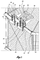
- FIGURE 6 is a detail view showing a portion of the fish pen 100 with the netting assembly 160 removed for clarity.
- a first internal wall 180 extends from the center spar buoy 110 to the upper and lower rim assemblies 140, 130 with a lower edge along the floor of the netting assembly 160 (not shown).
- the first internal wall 180 may be deployable, and configured to remain at a fixed position when deployed.
- a second internal wall 182 also extends from the center spar buoy 100 to the upper and lower rim assemblies 140, 130. Therefore, the first and second internal walls delineate a portion of the volume of the fish pen 100.
- the second internal wall 182 is preferably deployable and is configured to be swept circumferentially through the fish pen 100 with the inner edge remaining attached to the center spar buoy 100 and the outer edge movable along the netting assembly 160.
- the lower edge of the second internal wall 182 remains disposed generally at or near the floor portion of the netting assembly 160.
- the second inner wall 182 may be formed of a netting material to facilitate movement through the water.
- the second internal wall 182 may therefore be initially deployed adjacent the first internal wall 180, and moved around the center spar buoy to a location, for example, to the location shown in FIGURE 6 , thereby crowding fish in the fish pen 100 into a small region of the fish pen 100.
- This may be useful, for example, for extracting the fish from the fish pen 100 or for confining fish in one section to allow for maintenance on other portions of the fish pen 100.
- first and second inner walls 180, 182 may be formed from a nonporous material, for example, a plastic sheet or the like. Additionally, a similar nonporous internal wall 184 may be deployed along the vertical wall section of the netting assembly 160 adjacent the first and second inner walls 180, 182 and a similar nonporous internal floor section (not shown) may be deployed below the region defined by the first and second inner walls 180, 182. In this configuration, an enclosed region of the fish pen 100 may be selectively isolated from the surrounding body of water when the fish pen is in the raised position. The second inner wall 182 may be swept through the fish pen 100 pivoting about the center spar buoy 110 to crowd the fish into the defined region. Providing a smaller portion of the fish pen 100 substantially isolated from the surrounding body of water will facilitate, for example, treating the fish population when necessary.
- the fish pen 100 is moved to a raised position, the nonporous internal walls are deployed, and the second internal wall 182 is swept through the fish pen 100 to isolate the fish.
- a desired treatment may then be deposited into the isolated portion of water, and after waiting sufficient time, the internal wall portions may be retracted. It is contemplated, for example, that other steps may be desirable, for example providing aeration to the isolated water portion during treatment, providing food, etc.
- the fish pen 100 includes one or optionally more docking station 190 (two shown in FIGURE 2 ) that may include entryways into the fish pen 100.
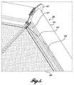
- FIGURE 7 is a detail view showing a docking station 190 disposed adjacent a closable portal 185.
- the portal 185 comprises large openings and one or more rigid framed doors 186 that can be opened to provide access to the interior of the fish pen 100.
- the portal may be used to stock the fish pen 100 or to remove fish, or to gain access for monitoring and/or maintenance of the fish pen 100 or fish. Conventional mechanisms for opening, closing, and/or securing the portal may be used.
- the portal may further include oppositely disposed fish trough panels or nets 187 that extend upright from the portal 185.
- the fish trough nets 187 in this embodiment are generally triangular and are operable to prevent fish from escaping from the portal 185 when the portal is open.
- the fish troughs are removable and/or fold down for securement to the netting assembly 160.
- the docking station 190 includes a plurality of upright fender members 191 fixed to the side of an upper rim segment 141 with a web member 192.
- the docking station 190 provides an energy absorbent contact location between a vessel 80 and the fish pen 100.
- the upright fender members 191 are preferably modular and attached to the upper rim segment 141 with removable fasteners such that they can be quickly and easily replaced.
- the upright fender members 191 in a current embodiment are fabricated from steel structural members with a hardened rubber marine grade material outer covering.
- the fender members 191 preferably extend high enough off the water that the railing of a moored vessel will not catch on the top of the fender member 191 from wave-induced motion.
- the lower portion of the fender members 191 bends in towards the fish pen 100 to avoid any unintended underwater interaction between the hull and the fender members 191.
- Conventional fender buoys 195 may also be provided.
- the nearby cleats 144 on the upper rim flange assembly 142 may be used to secure the watercraft 80 to the fish pen 100.
- the docking station 190 may further include a work platform 194 with a suitable handrail system 193, to facilitate operator activities, such as stocking or removing fish, performing maintenance, etc.
- the work platform 194 is affixed to one or more of the upper rim segments 141 and provides the workers with a safe sturdy location to perform normal farm operations.
- An optional opening in the handrail system 193 allows for easy access to the rim deck from both the fish pen side and ocean side of the work platform 194.
- the work platform 194 is fabricated from a non-metal material, such as fiberglass, to decrease weight and is porous to allow water to pass through. A non-skid finish is applied to the top side of the platform 194.
Claims (16)
- Ein Fischgehege (100) für Aquakultur umfassend:eine längliche zentrale Spierentonne (110) aufweisend einen oberen Spierenteil und einen unteren Spierenteil;eine an einem oberen Ende der zentralen Spierentonne (110) befestigte Reserveauftriebsboje (120);einen an dem unteren Spierenteil befestigten unteren Verbindungskragen (112);einen an dem oberen Spierenteil einstellbar befestigten oberen Verbindungskragen (114);einen unteren Rand (130) aufweisend eine Vielzahl von Flanschteilen;einen oberen Rand (140) aufweisend eine Vielzahl von Flanschteilen;eine Vielzahl an ersten Zugsträngen (150) aufweisend ein an dem unteren Verbindungskragen (112) befestigtes erstes Ende und ein an einem der korrespondierenden unteren Rand-Flanschteilen befestigtes zweites Ende;eine Vielzahl an zweiten Zugsträngen (152) aufweisend ein an einem der Vielzahl von unteren Rand-Flanschteilen befestigtes erstes Ende und ein an einem der korrespondierenden oberen Rand-Flanschteilen befestigtes zweites Ende;eine Vielzahl an dritten Zugsträngen (154) aufweisend ein an einem der oberen Rand-Flanschteilen befestigtes erstes Ende und ein an dem oberen Verbindungskragen (114) befestigtes zweites Ende;eine ein eingeschlossenes Volumen definierende Netzbaugruppe (160) umfassend(i) ein an dem unteren Rand (130) und der zentralen Spierentonne befestigtes Bodenteil,(ii) ein sich von dem Bodenteil nach oben erstreckendes Wandteil, und(iii) ein sich von dem Wandteil nach innen erstreckendes und an dem oberen Rand (140) sowie der zentralen Spierentonne (110) befestigtes Oberteil,ein erstes Innenpaneel (180) aufweisend einen an das Bodenteil angrenzenden unteren Rand,einen mit der zentralen Spierentonne in Verbindung stehender Innenrand und ein an die Netzbaugruppe des Wandteiles angrenzendes Außenteil,ein zweites Innenpaneel (182) aufweisend einen an das Bodenteil angrenzenden unteren Rand, einen mit der zentralen Spierentonne in Verbindung stehender Innenrand und ein an die Netzbaugruppe des Wandteiles angrenzendes Außenteil,wobei erstes und zweites Paneel (180,182) so ausgeführt sind, daß sie ein kleineres bearbeitbares Volumen innerhalb der Netzbaugruppe (160) abgrenzen, undeine Andockstation (190) umfassend ein aufrechtes Fenderglied (191) welches an dem oberen Rand (140) befestigt ist.
- Das Fischgehege (100) nach Anspruch 1, wobei die Reserveauftriebsboje (120) mit der zentralen Spierentonne (110) gleitend in Eingriff steht.
- Das Fischgehege (100) nach Anspruch 1 oder 2, wobei die Reserveauftriebsboje (120) ein zentrales Schlauchteil aufweist, welches so gestaltet ist, daß es mit einem oberen Ende der zentralen Spierentonne (110) gleitend im Eingriff steht.
- Das Fischgehege (100) nach Anspruch 1, 2 oder 3, wobei die Netzbaugruppe (160) weiterhin ein Mundloch (185) aufweist, welches Türelemente aufweist, um einen Zugang zu dem umschlossenen Volumen bereitzustellen.
- Das Fischgehege (100) nach einem der Ansprüche 1 bis 4, weiterhin aufweisend ein Paar gegenüberliegender beiderseits hochkant an dem Mundloch (185) angeordneter Fischkäfighalter.
- Das Fischgehege (100) nach einem der Ansprüche 1 bis 5, wobei das aufrechte Fenderglied (191) ein Stahlstrukturbauteil aufweist, mit einer marinetauglichen Außenabdeckung aus Hartkautschuk, und wobei weiterhin ein unteres Teil des aufrechten Fendergliedes (191) nach innen in Richtung zentraler Spierentonne (110) gebogen ist.
- Das Fischgehege (100) nach Anspruch 1 und 4, wobei die Andockstation (190) neben dem Mundloch (185) angeordnet ist, und weiterhin eine Arbeitsplattform (194) aufweist, die an dem oberen Rand (140) befestigt ist.
- Das Fischgehege (100) nach Anspruch 7, wobei die Arbeitsplattform (194) einen Handlauf (193) aufweist.
- Das Fischgehege (100) nach einem der Ansprüche 1 bis 8, wobei zumindest einige der Vielzahl an oberen Rand-Flanschteilen weiterhin eine Klemmenanordnung (144) aufweist dergestalt, daß ein einfaches Befestigen eines Wasserfahrzeuges (80) an das Fischgehege (100) ermöglicht ist.
- Das Fischgehege (100) nach einem der Ansprüche 1 bis 9, wobei die zentrale Spierentonne (110) weiterhin eine befestigte Netzanschlußplatte aufweist, und wobei die Netzbaugruppe (160) an der Netzanschlußplatte befestigt ist.
- Das Fischgehege (100) nach einem der Ansprüche 1 bis 10, wobei die ersten, zweiten und dritten Zugstränge (150,152,153) nicht direkt mit der Netzbaugruppe (160) in Eingriff stehen.
- Das Fischgehege (100) nach einem der Ansprüche 1 bis 11, wobei das zweite Innenpaneel (182) um die zentrale Spierentonne (110) drehbar ist.
- Das Fischgehege (100) nach einem der Ansprüche 1 bis 12, wobei das zweite Innenpaneel (182) aus einem durchlässigen maschenförmigen Material besteht, und wobei weiterhin der äußere Rand des zweiten Innenpaneels (182) so gestaltet ist, daß das zweite Innenpaneel (182) in einer kreisförmigen Bewegung um einen Teil des umschlossenen Volumens geschwenkt werden kann.
- Das Fischgehege (100) nach einem der Ansprüche 1 bis 13, wobei das erste und zweite Innenpaneel (180,182) undurchlässig ist, und wobei weiterhin ein drittes undurchlässiges Innenpaneel (184) neben der Netzbaugruppe (160) zwischen den ersten und zweiten Innenpaneelen (180,182) angebracht ist.
- Verfahren zum Halten von Fischen in freiem Wasser, aufweisend die folgenden Schritte:Bereitstellen eines Fischgeheges (100) welches eine längliche zentrale Spierentonne (110) aufweist; eine an einem oberen Ende der Spierentonne befestigte Reserveauftriebsboje (120); einen unteren Rand (130); einen oberen Rand (140); eine Vielzahl von Zugsträngen (150,152,154) dergestalt, daß der untere und der obere Rand an die Spierentonne (110) befestigt werden kann; eine ein umschlossenes Volumen definierende Netzbaugruppenanordnung (160) aufweisend(i) ein am unteren Rand (130) und der Spierentonne (110) befestigtes Bodenteil,(ii) ein von dem Bodenteil sich nach oben erstreckendes Wandteil,(iii) ein am oberen Rand (140) und der Spierentonne befestigtes Oberteil;ein erstes Innenpaneel (180) aufweisend einen an das Bodenteil angrenzenden unteren Rand, einen an die Spierentonne (110) befestigten inneren Rand, und einen an das Wandteil angrenzenden äußeren Rand;und ein zweites Innenpaneel (182) aufweisend einen an das Bodenteil angrenzenden unteren Rand, einen an die Spierentonne (110) angrenzenden inneren Rand, und einen an das Wandteil angrenzenden äußeren Rand;Andocken eines eine Vielzahl an lebenden Fischen enthaltendes Wasserfahrzeuges (80) an den oberen Rand (140);Deponieren der Vielzahl an lebenden Fischen in einem durch die Netzbaugruppe (160) definiertes eingeschlossenes Volumen,wobei der Außenrand des zweiten Paneels (182) um die Spierentonne (110) so drehbar ist, daß die Vielzahl an lebenden Fischen in einem schmaleren Bereich des durch die Netzbaugruppe (160) definierten eingeschlossenen Volumens zusammengedrängt werden kann, undwobei das Fischgehege (100) mit einer Andockstation (190) versehen ist, welche ein an dem oberen Rand (140) befestigtes aufrechtes Fenderglied (191) aufweist.
- Das Verfahren nach Anspruch 15, weiterhin aufweisend das Verankern des unteren Randes (130) des Fischgeheges (100) an einer Stelle derart, daß sich das Fischgehege (100) in einer Fließströmung von selbst so auszurichten vermag, daß die gegenüberliegende Seite dieser Stelle flußabwärts zeigt.
Priority Applications (2)
| Application Number | Priority Date | Filing Date | Title |
|---|---|---|---|
| PL11853125T PL2658368T3 (pl) | 2010-12-29 | 2011-12-28 | Kojec rybny ze środkowym masztem oraz sposób utrzymywania ryb w otwartych wodach |
| HRP20170109TT HRP20170109T1 (hr) | 2010-12-29 | 2017-01-23 | Kavez za uzgoj ribe sa središnjom plutačom i postupak zadržavanja ribe u otvorenim vodama |
Applications Claiming Priority (2)
| Application Number | Priority Date | Filing Date | Title |
|---|---|---|---|
| US201061428095P | 2010-12-29 | 2010-12-29 | |
| PCT/US2011/067610 WO2012092380A2 (en) | 2010-12-29 | 2011-12-28 | Center spar fish pen |
Publications (3)
| Publication Number | Publication Date |
|---|---|
| EP2658368A2 EP2658368A2 (de) | 2013-11-06 |
| EP2658368A4 EP2658368A4 (de) | 2014-05-21 |
| EP2658368B1 true EP2658368B1 (de) | 2016-11-23 |
Family
ID=46379600
Family Applications (1)
| Application Number | Title | Priority Date | Filing Date |
|---|---|---|---|
| EP11853125.0A Active EP2658368B1 (de) | 2010-12-29 | 2011-12-28 | Fischpark mit mittigem holm und verfahren zur fischbegrenzung im freiwasser |
Country Status (12)
| Country | Link |
|---|---|
| US (2) | US8683955B2 (de) |
| EP (1) | EP2658368B1 (de) |
| KR (1) | KR101948670B1 (de) |
| CA (1) | CA2823325C (de) |
| CY (1) | CY1118698T1 (de) |
| DK (1) | DK2658368T3 (de) |
| ES (1) | ES2615230T3 (de) |
| HR (1) | HRP20170109T1 (de) |
| NZ (1) | NZ613244A (de) |
| PL (1) | PL2658368T3 (de) |
| PT (1) | PT2658368T (de) |
| WO (1) | WO2012092380A2 (de) |
Families Citing this family (40)
| Publication number | Priority date | Publication date | Assignee | Title |
|---|---|---|---|---|
| US7284501B2 (en) | 2004-10-29 | 2007-10-23 | Ocean Farm Technologies, Inc. | Containment pens for finfish aquaculture |
| US20110315085A1 (en) * | 2010-06-24 | 2011-12-29 | Lindgren Peter B | Aquaculture geodesic fish cage |
| FR2996722A1 (fr) * | 2012-10-17 | 2014-04-18 | Serge Menard | Installation d'aquaculture de haute mer |
| CA2903130A1 (en) * | 2013-03-14 | 2014-10-02 | Stephen H. Page | Aquaculture containment pen |
| NO336552B1 (no) * | 2013-12-23 | 2015-09-28 | Ocean Farming As | Halvt nedsenkbar, sylindrisk merd, stengbare skott for en merd, samt en hevbar bunn for merden. |
| NO339207B1 (no) * | 2015-07-07 | 2016-11-14 | Fishglobe As | Lukket tank for oppdrett av fisk |
| ES2959226T3 (es) * | 2016-02-23 | 2024-02-21 | Innovasea Systems Inc | Corral de pesca de acuicultura con trampa de mortalidad |
| NO341376B1 (no) * | 2016-03-02 | 2017-10-23 | Akvadesign As | Oppdriftssystem for en merd |
| DE102016003239B4 (de) * | 2016-03-16 | 2019-02-14 | Christian Beck | Senkrecht versenkbarer mobiler Fischkäfig für einen Einsatz im offenen Meer (off-shore) und in Küsten-/ Uferbereichen (on-shore) |
| EP3439468A4 (de) | 2016-04-05 | 2019-12-25 | Hextech Canada Ltd. | Tauchfähiges netzgehegesystem |
| NO344466B1 (en) * | 2016-04-11 | 2019-12-23 | Seafarming Systems As | A floating fish farming plant and assembly of plants |
| CN106069925B (zh) * | 2016-06-23 | 2017-05-03 | 青岛启航网箱工程技术有限公司 | 一种海洋牧场浮球式围养设施的构建方法 |
| CN106305525A (zh) * | 2016-10-15 | 2017-01-11 | 广西润爽生态农业科技有限公司 | 三层网箱养鱼的方法 |
| NO20161999A1 (en) * | 2016-12-15 | 2018-06-18 | Ids Invest As | A floating arrangement for breeding fish and shellfish |
| GB2602753B (en) * | 2017-04-21 | 2023-01-18 | Viewpoint As | Fish pen system with compensation for wave motion |
| NO343042B1 (en) | 2017-07-31 | 2018-10-15 | Marad Norway As | Fish Farm |
| NO343420B1 (en) * | 2017-08-15 | 2019-03-04 | Spring Innovation As | Floatable container for fish farming |
| CA3076857A1 (en) * | 2017-09-28 | 2019-04-04 | Saulx Offshore | Semi-submersible spar-type offshore fish farm with detachable and pivotable coupling assembly |
| AU2018371718A1 (en) | 2017-11-22 | 2020-06-11 | InnovaSea Systems, Inc. | Submerged feed disperser for aquaculture system |
| DK179794B1 (en) * | 2017-12-06 | 2019-06-25 | Knud E. Hansen A/S | Offshore fish farm |
| US11877563B2 (en) * | 2018-02-12 | 2024-01-23 | David Fries | Biomimetic sentinel reef structures for optical sensing and communications |
| CN108739574B (zh) * | 2018-03-30 | 2021-09-28 | 中国水产科学研究院东海水产研究所 | 深远海刚构支撑养殖装置铜合金网装备方法及其养殖装置 |
| CN108739576B (zh) * | 2018-05-03 | 2021-08-27 | 青岛博鲁泽海洋科技有限公司 | 一种用于深远海鱼类养殖的复合式网箱 |
| US20200022341A1 (en) * | 2018-07-23 | 2020-01-23 | Powerchina Huadong Engineering Corporation Limited | Combined structure of a fishing net cage and floating wind turbine foundation and construction method for same |
| US11766030B2 (en) * | 2018-08-06 | 2023-09-26 | Northeastern University | Robotic aquaculture system and methods |
| CN109169458B (zh) * | 2018-08-20 | 2020-11-13 | 浙江海洋大学 | 空投后体积增长的鱼礁 |
| DK3849302T3 (da) * | 2018-09-14 | 2022-07-25 | Saulx Offshore | Havbundsfunderet halvt nedsænkeligt offshore-fiskebrug af rundholdttypen og fremgangsmåde til installering heraf |
| NO344396B1 (en) * | 2018-11-01 | 2019-11-25 | Mbs Int As | Offshore farming system |
| USD891707S1 (en) * | 2018-11-13 | 2020-07-28 | InnovaSea Systems, Inc. | Attachment structure for a fish pen feed disperser |
| GB2583130A (en) * | 2019-04-18 | 2020-10-21 | Impact9 Energy And Marine Ltd | A submersible pen system |
| EP3986126A4 (de) | 2019-06-18 | 2023-07-19 | InnovaSea Systems, Inc. | Fischbecken für aquakultur mit mortalitätsfalle |
| TWI703926B (zh) * | 2019-06-24 | 2020-09-11 | 鑫鑽藻業生物科技股份有限公司 | 養殖系統 |
| NO346348B1 (en) * | 2019-07-18 | 2022-06-20 | Fiskevelferd As | Fish farm |
| CA3146088A1 (en) | 2019-07-30 | 2021-02-04 | Mark Penner | Fish pen for open sea aquaculture |
| US10638729B2 (en) * | 2019-10-11 | 2020-05-05 | Yona Becher | Fishermen's island for growing 10,000 tons of fish and seafood in water-filled ring-tube fishery |
| US20220369607A1 (en) * | 2021-05-19 | 2022-11-24 | National Taiwan Ocean University | Controllable and stable sinking/floating system for cage aquaculture |
| EP4340604A1 (de) * | 2021-05-20 | 2024-03-27 | InnovaSea Systems, Inc. | Dynamisches auftriebssystem für tauchstift |
| US20220400636A1 (en) * | 2021-06-16 | 2022-12-22 | Taerra Systems, Inc. | Kelp growth apparatus and method for kelp harvesting |
| CN114190322B (zh) * | 2021-11-18 | 2023-02-10 | 湖南海博水产种业科技有限公司 | 一种鱼苗暂养系统 |
| NO347545B1 (en) * | 2022-03-08 | 2024-01-02 | Mmc First Process As | Crowding arrangement |
Family Cites Families (31)
| Publication number | Priority date | Publication date | Assignee | Title |
|---|---|---|---|---|
| US203399A (en) | 1878-05-07 | Improvement in buoys | ||
| US85126A (en) | 1868-12-22 | Improvement in safety-bathing- apparatus | ||
| US215031A (en) | 1879-05-06 | Improvement in fish-traps | ||
| US1485875A (en) | 1923-05-05 | 1924-03-04 | O'malley Tulley | Floating fish trap |
| US1614600A (en) | 1926-07-06 | 1927-01-18 | Cleaver George | Floating fish trap |
| US2606350A (en) | 1949-07-05 | 1952-08-12 | French Humboldt | Cable strain clamp |
| US3691994A (en) | 1971-05-06 | 1972-09-19 | Aqua Genetics Inc | Floating fish enclosure |
| US3702709A (en) | 1971-05-20 | 1972-11-14 | Frank E Shaffer | Cable connector |
| US3992737A (en) | 1975-12-11 | 1976-11-23 | Motorola, Inc. | Suspension system for underwater equipment |
| FR2345075A1 (fr) * | 1976-03-25 | 1977-10-21 | Goguel Olivier | Cage d'elevage de poissons |
| US4252081A (en) | 1979-02-16 | 1981-02-24 | Marine Aquaculture (Scotland) Limited | Fish cage and method of cleaning fish cage |
| DE2906517C2 (de) | 1979-02-20 | 1981-03-26 | Geroh GmbH Mechanische Systeme, 91344 Waischenfeld | Vorrichtung zum Führen und Festklemmen eines Seiles oder Kabels, insbesonders bei freistehenden Masten wie Masten von beweglichen Antennenanlagen oder auf Zelten mit Abspannseilen |
| GB2040652A (en) | 1979-02-21 | 1980-09-03 | Nat Res Dev | Rotatable fish cage |
| US4312296A (en) * | 1979-12-31 | 1982-01-26 | Yan Stelleman | Sea cage for farming fish |
| JPS602769Y2 (ja) | 1980-08-08 | 1985-01-25 | 株式会社ブリヂストン | いけす装置 |
| SE446053B (sv) * | 1984-11-21 | 1986-08-11 | Farmocean Ab | Anordning for odling av fisk i en netkasse vilken er uppburen av en ponton vars djuplege er varierbart |
| SE450866B (sv) | 1985-12-02 | 1987-08-10 | Farmocean Ab | Flytande odlingsanordning for fisk eller liknande |
| FR2596613A1 (fr) | 1986-04-02 | 1987-10-09 | Hardy Luc | Ensemble d'elevage d'animaux aquatiques et plus particulierement de poissons |
| JPS62172358U (de) | 1986-04-22 | 1987-10-31 | ||
| US5007376A (en) | 1989-04-18 | 1991-04-16 | Nor'eastern Trawl Systems, Inc. | Spar bouy pen system |
| EP0480114A1 (de) | 1990-08-21 | 1992-04-15 | Pisciculture Marine De Monaco S.A.M | Anlage zur Meerfischzucht |
| CA2108830A1 (en) | 1992-10-29 | 1994-04-29 | Gary F. Loverich | Center-spar fish pen |
| US5617813A (en) * | 1995-03-31 | 1997-04-08 | Ocean Spar Technologies, Llc | Anchorable mobile spar and ring fish pen |
| US6251405B1 (en) | 1995-06-07 | 2001-06-26 | Connaught Laboratories, Inc. | Immunological combination compositions and methods |
| US6044798A (en) | 1998-01-26 | 2000-04-04 | Princeton Abalone Inc. | Floating aquaculture apparatus |
| US6892672B2 (en) | 2000-07-03 | 2005-05-17 | F.F.T. Ltd. | Apparatus for breeding fish in open sea |
| NO20030592D0 (no) * | 2003-02-06 | 2003-02-06 | Endre Kvalheim | Fiskemerd |
| ES2246717B2 (es) | 2004-08-06 | 2006-11-16 | Andres Quinta Cortiñas | Vivero sumergible perfeccionado. |
| US20070169711A1 (en) * | 2006-01-25 | 2007-07-26 | Sims Neil A | Harvest cone for sea cage for fish-growing |
| US8028660B2 (en) * | 2006-10-10 | 2011-10-04 | Hawaii Oceanic Technology, Inc. | Automated positioning and submersible open ocean platform |
| US7748349B2 (en) | 2006-11-13 | 2010-07-06 | Open Ocean Systems, Inc. | Submersible cage and system for fish farming |
-
2011
- 2011-12-28 WO PCT/US2011/067610 patent/WO2012092380A2/en active Application Filing
- 2011-12-28 KR KR1020137020094A patent/KR101948670B1/ko active IP Right Grant
- 2011-12-28 PL PL11853125T patent/PL2658368T3/pl unknown
- 2011-12-28 DK DK11853125.0T patent/DK2658368T3/en active
- 2011-12-28 EP EP11853125.0A patent/EP2658368B1/de active Active
- 2011-12-28 NZ NZ613244A patent/NZ613244A/en unknown
- 2011-12-28 CA CA2823325A patent/CA2823325C/en active Active
- 2011-12-28 PT PT118531250T patent/PT2658368T/pt unknown
- 2011-12-28 ES ES11853125.0T patent/ES2615230T3/es active Active
- 2011-12-28 US US13/338,501 patent/US8683955B2/en active Active
-
2014
- 2014-02-21 US US14/187,054 patent/US9072282B2/en active Active
-
2017
- 2017-01-23 HR HRP20170109TT patent/HRP20170109T1/hr unknown
- 2017-02-01 CY CY20171100148T patent/CY1118698T1/el unknown
Also Published As
| Publication number | Publication date |
|---|---|
| US8683955B2 (en) | 2014-04-01 |
| WO2012092380A3 (en) | 2012-10-18 |
| AU2011352114A1 (en) | 2013-08-01 |
| WO2012092380A2 (en) | 2012-07-05 |
| PL2658368T3 (pl) | 2017-07-31 |
| ES2615230T3 (es) | 2017-06-06 |
| DK2658368T3 (en) | 2017-03-06 |
| US20140165922A1 (en) | 2014-06-19 |
| CA2823325C (en) | 2017-09-26 |
| HRP20170109T1 (hr) | 2017-04-07 |
| US20120167829A1 (en) | 2012-07-05 |
| EP2658368A4 (de) | 2014-05-21 |
| NZ613244A (en) | 2014-05-30 |
| PT2658368T (pt) | 2017-02-22 |
| CY1118698T1 (el) | 2017-07-12 |
| EP2658368A2 (de) | 2013-11-06 |
| KR101948670B1 (ko) | 2019-02-15 |
| CA2823325A1 (en) | 2012-07-05 |
| US9072282B2 (en) | 2015-07-07 |
| KR20140020859A (ko) | 2014-02-19 |
Similar Documents
| Publication | Publication Date | Title |
|---|---|---|
| EP2658368B1 (de) | Fischpark mit mittigem holm und verfahren zur fischbegrenzung im freiwasser | |
| US20220279764A1 (en) | System and method for modular aquaculture | |
| JP6923547B2 (ja) | 半潜水型養殖システム | |
| RU2690881C2 (ru) | Шельфовая установка для аквакультуры | |
| US5438958A (en) | Platform supported mariculture system | |
| EP1806964B1 (de) | Begrenzungszäune für eine flossenfisch-aquakultur | |
| RU2738412C1 (ru) | Плавучая конструкция для разведения рыбы и водных экзоскелетных животных | |
| EP3687286B1 (de) | Halbtauchende offshore-fischfarm vom holmtyp mit erfassbarer und schwenkbarer kopplungsanordnung | |
| AU2011238426A1 (en) | Aquaculture assembly and method | |
| EP1476011B1 (de) | Zucht und ernte von schalentieren | |
| US11737433B2 (en) | Aquatic cage rotation device | |
| CN113163736A (zh) | 离岸养殖系统 | |
| KR20180122000A (ko) | 전복 양식 장치 및 방법 | |
| CN101779602A (zh) | 气囊移动式网箱 | |
| EP3190878B1 (de) | System und verfahren zur verankerung | |
| AU2011352114B2 (en) | Center spar fish pen | |
| WO2023167596A1 (en) | Fish farming systems | |
| KR20160004171U (ko) | 전복양식용 가두리 | |
| RU2410873C1 (ru) | Плавучая ферма для разведения гидробионтов | |
| CN117413794A (zh) | 一种开放式网箱与封闭舱养一体化可移动渔业养殖平台 | |
| NO347569B1 (en) | Fish farm with working platform |
Legal Events
| Date | Code | Title | Description |
|---|---|---|---|
| PUAI | Public reference made under article 153(3) epc to a published international application that has entered the european phase |
Free format text: ORIGINAL CODE: 0009012 |
|
| 17P | Request for examination filed |
Effective date: 20130729 |
|
| AK | Designated contracting states |
Kind code of ref document: A2 Designated state(s): AL AT BE BG CH CY CZ DE DK EE ES FI FR GB GR HR HU IE IS IT LI LT LU LV MC MK MT NL NO PL PT RO RS SE SI SK SM TR |
|
| DAX | Request for extension of the european patent (deleted) | ||
| A4 | Supplementary search report drawn up and despatched |
Effective date: 20140424 |
|
| RIC1 | Information provided on ipc code assigned before grant |
Ipc: A01K 61/00 20060101AFI20140416BHEP Ipc: B63B 35/44 20060101ALI20140416BHEP |
|
| RIC1 | Information provided on ipc code assigned before grant |
Ipc: A01K 61/00 20060101AFI20160523BHEP |
|
| GRAP | Despatch of communication of intention to grant a patent |
Free format text: ORIGINAL CODE: EPIDOSNIGR1 |
|
| INTG | Intention to grant announced |
Effective date: 20160707 |
|
| GRAS | Grant fee paid |
Free format text: ORIGINAL CODE: EPIDOSNIGR3 |
|
| GRAA | (expected) grant |
Free format text: ORIGINAL CODE: 0009210 |
|
| AK | Designated contracting states |
Kind code of ref document: B1 Designated state(s): AL AT BE BG CH CY CZ DE DK EE ES FI FR GB GR HR HU IE IS IT LI LT LU LV MC MK MT NL NO PL PT RO RS SE SI SK SM TR |
|
| REG | Reference to a national code |
Ref country code: GB Ref legal event code: FG4D |
|
| REG | Reference to a national code |
Ref country code: CH Ref legal event code: EP |
|
| REG | Reference to a national code |
Ref country code: IE Ref legal event code: FG4D |
|
| REG | Reference to a national code |
Ref country code: AT Ref legal event code: REF Ref document number: 846999 Country of ref document: AT Kind code of ref document: T Effective date: 20161215 |
|
| REG | Reference to a national code |
Ref country code: DE Ref legal event code: R096 Ref document number: 602011032804 Country of ref document: DE |
|
| REG | Reference to a national code |
Ref country code: FR Ref legal event code: PLFP Year of fee payment: 6 |
|
| REG | Reference to a national code |
Ref country code: HR Ref legal event code: TUEP Ref document number: P20170109 Country of ref document: HR |
|
| REG | Reference to a national code |
Ref country code: RO Ref legal event code: EPE |
|
| REG | Reference to a national code |
Ref country code: SE Ref legal event code: TRGR |
|
| REG | Reference to a national code |
Ref country code: NL Ref legal event code: FP Ref country code: PT Ref legal event code: SC4A Ref document number: 2658368 Country of ref document: PT Date of ref document: 20170222 Kind code of ref document: T Free format text: AVAILABILITY OF NATIONAL TRANSLATION Effective date: 20170215 |
|
| PG25 | Lapsed in a contracting state [announced via postgrant information from national office to epo] |
Ref country code: LV Free format text: LAPSE BECAUSE OF FAILURE TO SUBMIT A TRANSLATION OF THE DESCRIPTION OR TO PAY THE FEE WITHIN THE PRESCRIBED TIME-LIMIT Effective date: 20161123 |
|
| REG | Reference to a national code |
Ref country code: DK Ref legal event code: T3 Effective date: 20170301 |
|
| REG | Reference to a national code |
Ref country code: LT Ref legal event code: MG4D |
|
| REG | Reference to a national code |
Ref country code: HR Ref legal event code: T1PR Ref document number: P20170109 Country of ref document: HR |
|
| REG | Reference to a national code |
Ref country code: NO Ref legal event code: T2 Effective date: 20161123 |
|
| REG | Reference to a national code |
Ref country code: AT Ref legal event code: MK05 Ref document number: 846999 Country of ref document: AT Kind code of ref document: T Effective date: 20161123 |
|
| PG25 | Lapsed in a contracting state [announced via postgrant information from national office to epo] |
Ref country code: LT Free format text: LAPSE BECAUSE OF FAILURE TO SUBMIT A TRANSLATION OF THE DESCRIPTION OR TO PAY THE FEE WITHIN THE PRESCRIBED TIME-LIMIT Effective date: 20161123 |
|
| PG25 | Lapsed in a contracting state [announced via postgrant information from national office to epo] |
Ref country code: AT Free format text: LAPSE BECAUSE OF FAILURE TO SUBMIT A TRANSLATION OF THE DESCRIPTION OR TO PAY THE FEE WITHIN THE PRESCRIBED TIME-LIMIT Effective date: 20161123 Ref country code: BE Free format text: LAPSE BECAUSE OF NON-PAYMENT OF DUE FEES Effective date: 20161231 Ref country code: RS Free format text: LAPSE BECAUSE OF FAILURE TO SUBMIT A TRANSLATION OF THE DESCRIPTION OR TO PAY THE FEE WITHIN THE PRESCRIBED TIME-LIMIT Effective date: 20161123 |
|
| REG | Reference to a national code |
Ref country code: ES Ref legal event code: FG2A Ref document number: 2615230 Country of ref document: ES Kind code of ref document: T3 Effective date: 20170606 |
|
| PG25 | Lapsed in a contracting state [announced via postgrant information from national office to epo] |
Ref country code: CZ Free format text: LAPSE BECAUSE OF FAILURE TO SUBMIT A TRANSLATION OF THE DESCRIPTION OR TO PAY THE FEE WITHIN THE PRESCRIBED TIME-LIMIT Effective date: 20161123 Ref country code: SK Free format text: LAPSE BECAUSE OF FAILURE TO SUBMIT A TRANSLATION OF THE DESCRIPTION OR TO PAY THE FEE WITHIN THE PRESCRIBED TIME-LIMIT Effective date: 20161123 Ref country code: EE Free format text: LAPSE BECAUSE OF FAILURE TO SUBMIT A TRANSLATION OF THE DESCRIPTION OR TO PAY THE FEE WITHIN THE PRESCRIBED TIME-LIMIT Effective date: 20161123 |
|
| REG | Reference to a national code |
Ref country code: CH Ref legal event code: PL |
|
| REG | Reference to a national code |
Ref country code: DE Ref legal event code: R097 Ref document number: 602011032804 Country of ref document: DE |
|
| PG25 | Lapsed in a contracting state [announced via postgrant information from national office to epo] |
Ref country code: BE Free format text: LAPSE BECAUSE OF FAILURE TO SUBMIT A TRANSLATION OF THE DESCRIPTION OR TO PAY THE FEE WITHIN THE PRESCRIBED TIME-LIMIT Effective date: 20161123 Ref country code: BG Free format text: LAPSE BECAUSE OF FAILURE TO SUBMIT A TRANSLATION OF THE DESCRIPTION OR TO PAY THE FEE WITHIN THE PRESCRIBED TIME-LIMIT Effective date: 20170223 Ref country code: SM Free format text: LAPSE BECAUSE OF FAILURE TO SUBMIT A TRANSLATION OF THE DESCRIPTION OR TO PAY THE FEE WITHIN THE PRESCRIBED TIME-LIMIT Effective date: 20161123 |
|
| PG25 | Lapsed in a contracting state [announced via postgrant information from national office to epo] |
Ref country code: MC Free format text: LAPSE BECAUSE OF FAILURE TO SUBMIT A TRANSLATION OF THE DESCRIPTION OR TO PAY THE FEE WITHIN THE PRESCRIBED TIME-LIMIT Effective date: 20161123 |
|
| PLBE | No opposition filed within time limit |
Free format text: ORIGINAL CODE: 0009261 |
|
| STAA | Information on the status of an ep patent application or granted ep patent |
Free format text: STATUS: NO OPPOSITION FILED WITHIN TIME LIMIT |
|
| PG25 | Lapsed in a contracting state [announced via postgrant information from national office to epo] |
Ref country code: CH Free format text: LAPSE BECAUSE OF NON-PAYMENT OF DUE FEES Effective date: 20161231 Ref country code: LU Free format text: LAPSE BECAUSE OF NON-PAYMENT OF DUE FEES Effective date: 20161228 Ref country code: LI Free format text: LAPSE BECAUSE OF NON-PAYMENT OF DUE FEES Effective date: 20161231 |
|
| 26N | No opposition filed |
Effective date: 20170824 |
|
| REG | Reference to a national code |
Ref country code: FR Ref legal event code: PLFP Year of fee payment: 7 |
|
| PG25 | Lapsed in a contracting state [announced via postgrant information from national office to epo] |
Ref country code: SI Free format text: LAPSE BECAUSE OF FAILURE TO SUBMIT A TRANSLATION OF THE DESCRIPTION OR TO PAY THE FEE WITHIN THE PRESCRIBED TIME-LIMIT Effective date: 20161123 |
|
| PG25 | Lapsed in a contracting state [announced via postgrant information from national office to epo] |
Ref country code: HU Free format text: LAPSE BECAUSE OF FAILURE TO SUBMIT A TRANSLATION OF THE DESCRIPTION OR TO PAY THE FEE WITHIN THE PRESCRIBED TIME-LIMIT; INVALID AB INITIO Effective date: 20111228 |
|
| PG25 | Lapsed in a contracting state [announced via postgrant information from national office to epo] |
Ref country code: MK Free format text: LAPSE BECAUSE OF FAILURE TO SUBMIT A TRANSLATION OF THE DESCRIPTION OR TO PAY THE FEE WITHIN THE PRESCRIBED TIME-LIMIT Effective date: 20161123 |
|
| REG | Reference to a national code |
Ref country code: HR Ref legal event code: ODRP Ref document number: P20170109 Country of ref document: HR Payment date: 20181106 Year of fee payment: 8 |
|
| REG | Reference to a national code |
Ref country code: HR Ref legal event code: ODRP Ref document number: P20170109 Country of ref document: HR Payment date: 20191029 Year of fee payment: 9 |
|
| PGFP | Annual fee paid to national office [announced via postgrant information from national office to epo] |
Ref country code: RO Payment date: 20191121 Year of fee payment: 9 |
|
| PGFP | Annual fee paid to national office [announced via postgrant information from national office to epo] |
Ref country code: HR Payment date: 20191029 Year of fee payment: 9 |
|
| REG | Reference to a national code |
Ref country code: FI Ref legal event code: PCE Owner name: INNOVASEA SYSTEMS, INC. |
|
| PG25 | Lapsed in a contracting state [announced via postgrant information from national office to epo] |
Ref country code: AL Free format text: LAPSE BECAUSE OF FAILURE TO SUBMIT A TRANSLATION OF THE DESCRIPTION OR TO PAY THE FEE WITHIN THE PRESCRIBED TIME-LIMIT Effective date: 20161123 |
|
| REG | Reference to a national code |
Ref country code: ES Ref legal event code: PC2A Owner name: INNOVASEA SYSTEMS, INC Effective date: 20200807 |
|
| REG | Reference to a national code |
Ref country code: NL Ref legal event code: PD Owner name: INNOVASEA SYSTEMS, INC.; US Free format text: DETAILS ASSIGNMENT: CHANGE OF OWNER(S), ASSIGNMENT; FORMER OWNER NAME: OCEANSPAR, INC Effective date: 20200826 |
|
| REG | Reference to a national code |
Ref country code: HR Ref legal event code: PPPP Ref document number: P20170109 Country of ref document: HR Owner name: INNOVASEA SYSTEMS, INC., US |
|
| REG | Reference to a national code |
Ref country code: DE Ref legal event code: R082 Ref document number: 602011032804 Country of ref document: DE Representative=s name: MITSCHERLICH, PATENT- UND RECHTSANWAELTE PARTM, DE Ref country code: DE Ref legal event code: R081 Ref document number: 602011032804 Country of ref document: DE Owner name: INNOVASEA SYSTEMS, INC., BOSTON, US Free format text: FORMER OWNER: OCEANSPAR, INC, AUGUSTA, ME., US |
|
| REG | Reference to a national code |
Ref country code: HR Ref legal event code: PBON Ref document number: P20170109 Country of ref document: HR Effective date: 20201228 |
|
| PG25 | Lapsed in a contracting state [announced via postgrant information from national office to epo] |
Ref country code: RO Free format text: LAPSE BECAUSE OF NON-PAYMENT OF DUE FEES Effective date: 20201228 |
|
| PG25 | Lapsed in a contracting state [announced via postgrant information from national office to epo] |
Ref country code: HR Free format text: LAPSE BECAUSE OF NON-PAYMENT OF DUE FEES Effective date: 20201228 |
|
| REG | Reference to a national code |
Ref country code: NO Ref legal event code: CHAD Owner name: INNOVASEA SYSTEMS INC, US |
|
| PGFP | Annual fee paid to national office [announced via postgrant information from national office to epo] |
Ref country code: PL Payment date: 20211222 Year of fee payment: 11 Ref country code: MT Payment date: 20211229 Year of fee payment: 11 |
|
| PGFP | Annual fee paid to national office [announced via postgrant information from national office to epo] |
Ref country code: IT Payment date: 20211230 Year of fee payment: 11 |
|
| PGFP | Annual fee paid to national office [announced via postgrant information from national office to epo] |
Ref country code: ES Payment date: 20230216 Year of fee payment: 12 |
|
| PGFP | Annual fee paid to national office [announced via postgrant information from national office to epo] |
Ref country code: TR Payment date: 20230216 Year of fee payment: 12 Ref country code: CY Payment date: 20230217 Year of fee payment: 12 |
|
| PGFP | Annual fee paid to national office [announced via postgrant information from national office to epo] |
Ref country code: NL Payment date: 20231123 Year of fee payment: 13 |
|
| PGFP | Annual fee paid to national office [announced via postgrant information from national office to epo] |
Ref country code: GR Payment date: 20231129 Year of fee payment: 13 Ref country code: GB Payment date: 20231123 Year of fee payment: 13 |
|
| PGFP | Annual fee paid to national office [announced via postgrant information from national office to epo] |
Ref country code: IS Payment date: 20231212 Year of fee payment: 13 |
|
| PG25 | Lapsed in a contracting state [announced via postgrant information from national office to epo] |
Ref country code: IT Free format text: LAPSE BECAUSE OF NON-PAYMENT OF DUE FEES Effective date: 20221228 |
|
| PGFP | Annual fee paid to national office [announced via postgrant information from national office to epo] |
Ref country code: SE Payment date: 20231127 Year of fee payment: 13 Ref country code: PT Payment date: 20231226 Year of fee payment: 13 Ref country code: NO Payment date: 20231212 Year of fee payment: 13 Ref country code: IE Payment date: 20231123 Year of fee payment: 13 Ref country code: FR Payment date: 20231122 Year of fee payment: 13 Ref country code: FI Payment date: 20231218 Year of fee payment: 13 Ref country code: DK Payment date: 20231215 Year of fee payment: 13 Ref country code: DE Payment date: 20231121 Year of fee payment: 13 |