EP2658287A1 - Oscillator device and electronic instrument - Google Patents
Oscillator device and electronic instrument Download PDFInfo
- Publication number
- EP2658287A1 EP2658287A1 EP11851199.7A EP11851199A EP2658287A1 EP 2658287 A1 EP2658287 A1 EP 2658287A1 EP 11851199 A EP11851199 A EP 11851199A EP 2658287 A1 EP2658287 A1 EP 2658287A1
- Authority
- EP
- European Patent Office
- Prior art keywords
- oscillator device
- piezoelectric
- elastic member
- piezoelectric vibrators
- ultrasonic waves
- Prior art date
- Legal status (The legal status is an assumption and is not a legal conclusion. Google has not performed a legal analysis and makes no representation as to the accuracy of the status listed.)
- Withdrawn
Links
Images



Classifications
-
- H—ELECTRICITY
- H03—ELECTRONIC CIRCUITRY
- H03B—GENERATION OF OSCILLATIONS, DIRECTLY OR BY FREQUENCY-CHANGING, BY CIRCUITS EMPLOYING ACTIVE ELEMENTS WHICH OPERATE IN A NON-SWITCHING MANNER; GENERATION OF NOISE BY SUCH CIRCUITS
- H03B5/00—Generation of oscillations using amplifier with regenerative feedback from output to input
- H03B5/30—Generation of oscillations using amplifier with regenerative feedback from output to input with frequency-determining element being electromechanical resonator
- H03B5/32—Generation of oscillations using amplifier with regenerative feedback from output to input with frequency-determining element being electromechanical resonator being a piezoelectric resonator
-
- H—ELECTRICITY
- H04—ELECTRIC COMMUNICATION TECHNIQUE
- H04R—LOUDSPEAKERS, MICROPHONES, GRAMOPHONE PICK-UPS OR LIKE ACOUSTIC ELECTROMECHANICAL TRANSDUCERS; ELECTRIC HEARING AIDS; PUBLIC ADDRESS SYSTEMS
- H04R17/00—Piezoelectric transducers; Electrostrictive transducers
-
- B—PERFORMING OPERATIONS; TRANSPORTING
- B06—GENERATING OR TRANSMITTING MECHANICAL VIBRATIONS IN GENERAL
- B06B—METHODS OR APPARATUS FOR GENERATING OR TRANSMITTING MECHANICAL VIBRATIONS OF INFRASONIC, SONIC, OR ULTRASONIC FREQUENCY, e.g. FOR PERFORMING MECHANICAL WORK IN GENERAL
- B06B1/00—Methods or apparatus for generating mechanical vibrations of infrasonic, sonic, or ultrasonic frequency
- B06B1/02—Methods or apparatus for generating mechanical vibrations of infrasonic, sonic, or ultrasonic frequency making use of electrical energy
- B06B1/0207—Driving circuits
- B06B1/0223—Driving circuits for generating signals continuous in time
- B06B1/0238—Driving circuits for generating signals continuous in time of a single frequency, e.g. a sine-wave
- B06B1/0246—Driving circuits for generating signals continuous in time of a single frequency, e.g. a sine-wave with a feedback signal
-
- B—PERFORMING OPERATIONS; TRANSPORTING
- B06—GENERATING OR TRANSMITTING MECHANICAL VIBRATIONS IN GENERAL
- B06B—METHODS OR APPARATUS FOR GENERATING OR TRANSMITTING MECHANICAL VIBRATIONS OF INFRASONIC, SONIC, OR ULTRASONIC FREQUENCY, e.g. FOR PERFORMING MECHANICAL WORK IN GENERAL
- B06B1/00—Methods or apparatus for generating mechanical vibrations of infrasonic, sonic, or ultrasonic frequency
- B06B1/02—Methods or apparatus for generating mechanical vibrations of infrasonic, sonic, or ultrasonic frequency making use of electrical energy
- B06B1/06—Methods or apparatus for generating mechanical vibrations of infrasonic, sonic, or ultrasonic frequency making use of electrical energy operating with piezoelectric effect or with electrostriction
- B06B1/0607—Methods or apparatus for generating mechanical vibrations of infrasonic, sonic, or ultrasonic frequency making use of electrical energy operating with piezoelectric effect or with electrostriction using multiple elements
- B06B1/0622—Methods or apparatus for generating mechanical vibrations of infrasonic, sonic, or ultrasonic frequency making use of electrical energy operating with piezoelectric effect or with electrostriction using multiple elements on one surface
-
- G—PHYSICS
- G01—MEASURING; TESTING
- G01S—RADIO DIRECTION-FINDING; RADIO NAVIGATION; DETERMINING DISTANCE OR VELOCITY BY USE OF RADIO WAVES; LOCATING OR PRESENCE-DETECTING BY USE OF THE REFLECTION OR RERADIATION OF RADIO WAVES; ANALOGOUS ARRANGEMENTS USING OTHER WAVES
- G01S15/00—Systems using the reflection or reradiation of acoustic waves, e.g. sonar systems
- G01S15/02—Systems using the reflection or reradiation of acoustic waves, e.g. sonar systems using reflection of acoustic waves
- G01S15/06—Systems determining the position data of a target
- G01S15/08—Systems for measuring distance only
-
- G—PHYSICS
- G01—MEASURING; TESTING
- G01S—RADIO DIRECTION-FINDING; RADIO NAVIGATION; DETERMINING DISTANCE OR VELOCITY BY USE OF RADIO WAVES; LOCATING OR PRESENCE-DETECTING BY USE OF THE REFLECTION OR RERADIATION OF RADIO WAVES; ANALOGOUS ARRANGEMENTS USING OTHER WAVES
- G01S7/00—Details of systems according to groups G01S13/00, G01S15/00, G01S17/00
- G01S7/52—Details of systems according to groups G01S13/00, G01S15/00, G01S17/00 of systems according to group G01S15/00
- G01S7/521—Constructional features
-
- H—ELECTRICITY
- H04—ELECTRIC COMMUNICATION TECHNIQUE
- H04R—LOUDSPEAKERS, MICROPHONES, GRAMOPHONE PICK-UPS OR LIKE ACOUSTIC ELECTROMECHANICAL TRANSDUCERS; ELECTRIC HEARING AIDS; PUBLIC ADDRESS SYSTEMS
- H04R1/00—Details of transducers, loudspeakers or microphones
- H04R1/20—Arrangements for obtaining desired frequency or directional characteristics
- H04R1/32—Arrangements for obtaining desired frequency or directional characteristics for obtaining desired directional characteristic only
- H04R1/40—Arrangements for obtaining desired frequency or directional characteristics for obtaining desired directional characteristic only by combining a number of identical transducers
- H04R1/403—Arrangements for obtaining desired frequency or directional characteristics for obtaining desired directional characteristic only by combining a number of identical transducers loud-speakers
-
- H—ELECTRICITY
- H04—ELECTRIC COMMUNICATION TECHNIQUE
- H04R—LOUDSPEAKERS, MICROPHONES, GRAMOPHONE PICK-UPS OR LIKE ACOUSTIC ELECTROMECHANICAL TRANSDUCERS; ELECTRIC HEARING AIDS; PUBLIC ADDRESS SYSTEMS
- H04R2201/00—Details of transducers, loudspeakers or microphones covered by H04R1/00 but not provided for in any of its subgroups
- H04R2201/40—Details of arrangements for obtaining desired directional characteristic by combining a number of identical transducers covered by H04R1/40 but not provided for in any of its subgroups
- H04R2201/403—Linear arrays of transducers
-
- H—ELECTRICITY
- H04—ELECTRIC COMMUNICATION TECHNIQUE
- H04R—LOUDSPEAKERS, MICROPHONES, GRAMOPHONE PICK-UPS OR LIKE ACOUSTIC ELECTROMECHANICAL TRANSDUCERS; ELECTRIC HEARING AIDS; PUBLIC ADDRESS SYSTEMS
- H04R2217/00—Details of magnetostrictive, piezoelectric, or electrostrictive transducers covered by H04R15/00 or H04R17/00 but not provided for in any of their subgroups
- H04R2217/03—Parametric transducers where sound is generated or captured by the acoustic demodulation of amplitude modulated ultrasonic waves
-
- H—ELECTRICITY
- H04—ELECTRIC COMMUNICATION TECHNIQUE
- H04R—LOUDSPEAKERS, MICROPHONES, GRAMOPHONE PICK-UPS OR LIKE ACOUSTIC ELECTROMECHANICAL TRANSDUCERS; ELECTRIC HEARING AIDS; PUBLIC ADDRESS SYSTEMS
- H04R2499/00—Aspects covered by H04R or H04S not otherwise provided for in their subgroups
- H04R2499/10—General applications
- H04R2499/11—Transducers incorporated or for use in hand-held devices, e.g. mobile phones, PDA's, camera's
Definitions
- the present invention relates to an oscillator device having a piezoelectric vibrator, and an electronic instrument using the oscillator device.
- Patent Documents 1 and 2 various types of electro-acoustic transducers described above have been proposed (for example, Patent Documents 1 and 2).
- a method is adapted in which a main beam is generated by composing the ultrasonic waves oscillated by changes of a timing from an array probe in which a plurality of fine ultrasonic wave vibrators are arranged.
- the method it is necessary to arrange a plurality of piezoelectric vibrators in an array, and thus the size of an oscillator device increases.
- the invention is contrived in view of such circumstances, and an object thereof is to provide a small-sized oscillator device having a high directivity and an electronic instrument using the oscillator device.
- An oscillator device of the invention includes a plurality of piezoelectric vibrators of which each has an elastic member and a piezoelectric element attached to the elastic member, and a supporting member that supports the plurality of piezoelectric vibrators.
- the supporting member has an opening.
- the plurality of piezoelectric vibrators are arranged in the opening along a first direction.
- a first electronic instrument of the invention has the oscillator device of the invention, and an oscillation driving unit that causes the oscillator device to output ultrasonic waves demodulated into sound waves of an audible zone.
- a second electronic instrument of the invention has the oscillator device of the invention, an oscillation driving unit that causes the oscillator device to output ultrasonic waves, an ultrasonic wave detection unit that detects sound waves having the same frequency as the ultrasonic waves, and a distance measurement unit that measures a distance to an object to be measured on the basis of the detected ultrasonic waves.
- the oscillator device of the invention it is possible to increase the directivity of the oscillator device without increasing the size of the oscillator device.
- the electro-acoustic transducer 100 which is an oscillator device of the embodiment will be described with reference to FIGS. 1 and 2 .
- the electro-acoustic transducer 100 of the embodiment has a plurality of piezoelectric vibrators 110 and a supporting member 120.
- Each of the piezoelectric vibrators 110 has an elastic member 112 and a piezoelectric element 111.
- the piezoelectric element 111 is attached to the elastic member 112.
- the supporting member 120 has an opening.
- the plurality of piezoelectric vibrators 110 are arranged in the opening along a first direction (horizontal direction in FIG. 1 ).
- the elastic member 112 has an elongate shape, for example, an oblong shape.
- the elastic member 112 is formed of, for example, phosphor bronze or stainless steel.
- the thickness of the elastic member 112 is preferably equal to or more than 5 ⁇ m and equal to or less than 500 ⁇ m.
- the elastic member 112 have a longitudinal elastic modulus, which is an index indicating stiffness, of equal to or more than 1 Gpa and equal to or less than 500 GPa.
- the piezoelectric element 111 is disposed in the center of the elastic member 112 when seen in a plan view.
- the piezoelectric element 111 is formed of, for example, piezoelectric ceramic, but may be formed of an organic material having a piezoelectric property. A surface of the piezoelectric element 111 which faces the elastic member 112 is entirely constrained by the elastic member 112.
- the exterior of the supporting member 120 has an oblong shape, and the opening has also an oblong shape.
- a beam or the like is not formed in the opening.
- a short side of the elastic member 112 is fixed to a lateral surface of a long side of the opening of the supporting member 120.
- all the piezoelectric vibrators 110 positioned inside the opening are arranged in a row along the first direction.
- the plurality of piezoelectric vibrators 110 have the same fundamental resonance frequency.
- An arrangement pitch X1 of the plurality of piezoelectric vibrators 110 is equal to or less than half of the fundamental resonance frequency of the piezoelectric vibrators.
- the piezoelectric vibrators 110 are regularly arranged in such a manner that mutual vibrating surfaces do not overlap with each other in the supporting member 120 when seen in a plan view.
- a machine quality coefficient Q of the piezoelectric vibrator 110 is adjusted to equal to or more than 50.
- the width of the piezoelectric vibrator 110 is the same as that of the elastic member 112. In other words, the piezoelectric vibrator 110 is positioned throughout the entire width in the center portion of the elastic member 112. Further, a driver circuit 130 is connected to the plurality of piezoelectric vibrators 110. The driver circuit 130 outputs sound waves by inputting oscillation signals to the piezoelectric vibrators 110. For example, the oscillation signal has the same frequency as the fundamental resonance frequency of the piezoelectric vibrator 110.
- the piezoelectric element 111 of the piezoelectric vibrator 110 when the signal is input to the piezoelectric element 111 of the piezoelectric vibrator 110, the piezoelectric element 111 and the elastic member 112 move expansively and contractively. Sound waves are generated by the expansion and contraction vibration.
- the sound waves are, for example, ultrasonic waves having a frequency of 20 kHz or more. Since the piezoelectric element 111 has a high machine quality coefficient Q, energy is concentrated on the vicinity of a fundamental resonance frequency. Thus, a high sound pressure level can be obtained in the fundamental resonance frequency, but sound pressure attenuates in other frequency bands.
- the oscillator device When the oscillator device is used as a parametric speaker, the oscillator device needs to oscillate ultrasonic waves limited to a specific frequency. Thus, there is an advantage in that the piezoelectric element 111 has the high machine quality coefficient Q.
- the fundamental resonance frequency of the piezoelectric vibrator 110 is influenced by the shape and size of the piezoelectric element 111. It is preferable to reduce the size of the piezoelectric element 111 in order to adjust a resonance frequency to a high frequency band, for example, an ultrasonic wave band. Thus, there is a tendency for a reduction in the size of the electro-acoustic transducer 100.
- the driver circuit 130 causes the piezoelectric vibrator 110 to oscillate ultrasonic waves on which, for example, FM (Frequency Modulation) or AM (Amplitude Modulation) is performed.
- the ultrasonic waves are demodulated into audible sounds by a non-linear state (sparse and dense state) of air.
- the oscillator device functions as a parametric speaker
- the ultrasonic waves have a high straightness, and thus it is possible to form a sound field having super-directivity.
- the piezoelectric vibrators 110 are arranged in an one-dimensional array.
- the plurality of piezoelectric vibrators 110 are arranged in the same opening provided in the supporting member 120 along the first direction.
- the phases of the sound waves oscillated from the adjacent piezoelectric vibrators 110 become opposite phases to each other, and thus it is possible to prevent the sound waves from canceling each other. Therefore, the directivity of the sound waves can be narrowed with high efficiency.
- the piezoelectric element 111 is disposed in the center portion of the elastic member 112 in all the piezoelectric vibrators 110.
- the machine quality coefficient Q of the piezoelectric vibrator 110 is high. Thus, it is possible to cause portions that are most strongly radiating the sound waves in the piezoelectric vibrator 110 to be adjacent to each other. Therefore, the above-described effects become pronounced.
- the driver circuit 130 drives the plurality of piezoelectric elements 111
- the same driving signal may be input to all the piezoelectric elements 111, or driving signals to be input to the plurality of piezoelectric elements 111 may be individually controlled. In the latter case, the directivity of the sound waves can be finely controlled.
- the piezoelectric vibrator 110 illustrated in FIG. 2 has a unimorph structure in which the piezoelectric element 111 is provided on only one surface of the elastic member 112.
- a piezoelectric vibrator 210 having a bimorph structure in which the piezoelectric element 111 is provided on both surfaces of the elastic member 112 may be used. In this case, the output of the piezoelectric vibrator 110 can be increased.
- the piezoelectric element 111 is constituted by one piezoelectric layer.
- the piezoelectric element 111 may have a layered structure in which a piezoelectric layer and an electrode layer are alternately stacked thereon (not shown).
- the driver circuit 130 for outputting an audible sound is connected to the electro-acoustic transducer 100.
- the electronic instrument may be a sonar including the electro-acoustic transducer 100, an oscillation driving unit 140 that causes the electro-acoustic transducer 100 to output ultrasonic waves, an ultrasonic wave detection unit 150 that detects sound waves (for example, ultrasonic waves reflected by an object to be measured) having the same frequency as the ultrasonic waves oscillated from the electro-acoustic transducer 100, and a distance measurement unit 160 that measures a distance to the object to be measured on the basis of the detected ultrasonic waves.
Landscapes
- Engineering & Computer Science (AREA)
- Mechanical Engineering (AREA)
- Physics & Mathematics (AREA)
- Acoustics & Sound (AREA)
- Signal Processing (AREA)
- Transducers For Ultrasonic Waves (AREA)
- Circuit For Audible Band Transducer (AREA)
Abstract
Description
- The present invention relates to an oscillator device having a piezoelectric vibrator, and an electronic instrument using the oscillator device.
- In cellular phones, sound functions such as a video phone call, moving image reproduction, or a hands-free function are required to be enhanced. Accordingly, it is expected that electro-acoustic transducers that are made small and have a large volume level output high power without increasing the size of the electro-acoustic transducers. In addition, from the viewpoint of privacy protection, superdirective speakers capable of forming a sound field at only a specific position are also required. An example of a superdirective speaker, a parametric speaker that uses ultrasonic waves for carrier waves of a sound or the like to demodulate the ultrasonic waves by non-linearity in air has been developed.
- At present, various types of electro-acoustic transducers described above have been proposed (for example,
Patent Documents 1 and 2). -
- [Patent Document 1] PCT Japanese Patent Domestic Re-publication No.
WO2008/142867 - [Patent Document 2] Japanese Unexamined Patent Publication No.
11-331985 - When the directivity of ultrasonic waves is narrowed down, like a phased array method, a method is adapted in which a main beam is generated by composing the ultrasonic waves oscillated by changes of a timing from an array probe in which a plurality of fine ultrasonic wave vibrators are arranged. When the method is employed, it is necessary to arrange a plurality of piezoelectric vibrators in an array, and thus the size of an oscillator device increases.
- The invention is contrived in view of such circumstances, and an object thereof is to provide a small-sized oscillator device having a high directivity and an electronic instrument using the oscillator device.
- An oscillator device of the invention includes a plurality of piezoelectric vibrators of which each has an elastic member and a piezoelectric element attached to the elastic member, and a supporting member that supports the plurality of piezoelectric vibrators. The supporting member has an opening. The plurality of piezoelectric vibrators are arranged in the opening along a first direction.
- A first electronic instrument of the invention has the oscillator device of the invention, and an oscillation driving unit that causes the oscillator device to output ultrasonic waves demodulated into sound waves of an audible zone.
- A second electronic instrument of the invention has the oscillator device of the invention, an oscillation driving unit that causes the oscillator device to output ultrasonic waves, an ultrasonic wave detection unit that detects sound waves having the same frequency as the ultrasonic waves, and a distance measurement unit that measures a distance to an object to be measured on the basis of the detected ultrasonic waves.
- According to the oscillator device of the invention, it is possible to increase the directivity of the oscillator device without increasing the size of the oscillator device.
- The above-described objects, other objects, features and advantages will be further apparent from the preferred embodiments described below, and the accompanying drawings as follows.
-
-
FIG. 1 is a schematic plan view illustrating a structure of an electro-acoustic transducer which is an oscillator device according to an embodiment of the invention. -
FIG. 2 is a schematic vertical cross-sectional front view illustrating structures of main parts of the electro-acoustic transducer. -
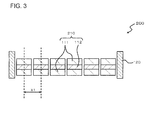
FIG. 3 is a schematic vertical cross-sectional front view illustrating structures of main parts of an electro-acoustic transducer according to a modified example. -
FIG. 4 is a diagram illustrating a configuration of an electronic instrument according to a modified example. - Hereinafter, an electro-
acoustic transducer 100 which is an oscillator device of the embodiment will be described with reference toFIGS. 1 and2 . As illustrated inFIG. 1 , the electro-acoustic transducer 100 of the embodiment has a plurality ofpiezoelectric vibrators 110 and a supportingmember 120. Each of thepiezoelectric vibrators 110 has anelastic member 112 and apiezoelectric element 111. Thepiezoelectric element 111 is attached to theelastic member 112. The supportingmember 120 has an opening. The plurality ofpiezoelectric vibrators 110 are arranged in the opening along a first direction (horizontal direction inFIG. 1 ). - More specifically, the
elastic member 112 has an elongate shape, for example, an oblong shape. Theelastic member 112 is formed of, for example, phosphor bronze or stainless steel. The thickness of theelastic member 112 is preferably equal to or more than 5 µm and equal to or less than 500 µm. In addition, it is preferable that theelastic member 112 have a longitudinal elastic modulus, which is an index indicating stiffness, of equal to or more than 1 Gpa and equal to or less than 500 GPa. - The
piezoelectric element 111 is disposed in the center of theelastic member 112 when seen in a plan view. Thepiezoelectric element 111 is formed of, for example, piezoelectric ceramic, but may be formed of an organic material having a piezoelectric property. A surface of thepiezoelectric element 111 which faces theelastic member 112 is entirely constrained by theelastic member 112. - The exterior of the supporting
member 120 has an oblong shape, and the opening has also an oblong shape. A beam or the like is not formed in the opening. A short side of theelastic member 112 is fixed to a lateral surface of a long side of the opening of the supportingmember 120. In the example illustrated in the drawing, all thepiezoelectric vibrators 110 positioned inside the opening are arranged in a row along the first direction. - Meanwhile, the plurality of
piezoelectric vibrators 110 have the same fundamental resonance frequency. An arrangement pitch X1 of the plurality ofpiezoelectric vibrators 110 is equal to or less than half of the fundamental resonance frequency of the piezoelectric vibrators. Thepiezoelectric vibrators 110 are regularly arranged in such a manner that mutual vibrating surfaces do not overlap with each other in the supportingmember 120 when seen in a plan view. In addition, a machine quality coefficient Q of thepiezoelectric vibrator 110 is adjusted to equal to or more than 50. - In addition, the width of the
piezoelectric vibrator 110 is the same as that of theelastic member 112. In other words, thepiezoelectric vibrator 110 is positioned throughout the entire width in the center portion of theelastic member 112. Further, adriver circuit 130 is connected to the plurality ofpiezoelectric vibrators 110. Thedriver circuit 130 outputs sound waves by inputting oscillation signals to thepiezoelectric vibrators 110. For example, the oscillation signal has the same frequency as the fundamental resonance frequency of thepiezoelectric vibrator 110. - In detail, when the signal is input to the
piezoelectric element 111 of thepiezoelectric vibrator 110, thepiezoelectric element 111 and theelastic member 112 move expansively and contractively. Sound waves are generated by the expansion and contraction vibration. The sound waves are, for example, ultrasonic waves having a frequency of 20 kHz or more. Since thepiezoelectric element 111 has a high machine quality coefficient Q, energy is concentrated on the vicinity of a fundamental resonance frequency. Thus, a high sound pressure level can be obtained in the fundamental resonance frequency, but sound pressure attenuates in other frequency bands. - When the oscillator device is used as a parametric speaker, the oscillator device needs to oscillate ultrasonic waves limited to a specific frequency. Thus, there is an advantage in that the
piezoelectric element 111 has the high machine quality coefficient Q. In addition, the fundamental resonance frequency of thepiezoelectric vibrator 110 is influenced by the shape and size of thepiezoelectric element 111. It is preferable to reduce the size of thepiezoelectric element 111 in order to adjust a resonance frequency to a high frequency band, for example, an ultrasonic wave band. Thus, there is a tendency for a reduction in the size of the electro-acoustic transducer 100. - Meanwhile, when the oscillator device functions as a parametric speaker, the
driver circuit 130 causes thepiezoelectric vibrator 110 to oscillate ultrasonic waves on which, for example, FM (Frequency Modulation) or AM (Amplitude Modulation) is performed. The ultrasonic waves are demodulated into audible sounds by a non-linear state (sparse and dense state) of air. - When the oscillator device functions as a parametric speaker, the ultrasonic waves have a high straightness, and thus it is possible to form a sound field having super-directivity. Meanwhile, it is preferable to radiate sound waves from the plurality of
piezoelectric vibrators 110 arranged in an array in order to control the directivity of the sound waves, like a phased array method. Even in the electro-acoustic transducer 100, thepiezoelectric vibrators 110 are arranged in an one-dimensional array. - Hereinafter, operations and effects of the embodiment will be described. In the electro-
acoustic transducer 100 of the embodiment, the plurality ofpiezoelectric vibrators 110 are arranged in the same opening provided in the supportingmember 120 along the first direction. Thus, it is possible to bring the adjacentpiezoelectric vibrators 110 close to each other. Accordingly, the phases of the sound waves oscillated from the adjacentpiezoelectric vibrators 110 become opposite phases to each other, and thus it is possible to prevent the sound waves from canceling each other. Therefore, the directivity of the sound waves can be narrowed with high efficiency. - Particularly, in the embodiment, the
piezoelectric element 111 is disposed in the center portion of theelastic member 112 in all thepiezoelectric vibrators 110. The machine quality coefficient Q of thepiezoelectric vibrator 110 is high. Thus, it is possible to cause portions that are most strongly radiating the sound waves in thepiezoelectric vibrator 110 to be adjacent to each other. Therefore, the above-described effects become pronounced. - Meanwhile, when the
driver circuit 130 drives the plurality ofpiezoelectric elements 111, the same driving signal may be input to all thepiezoelectric elements 111, or driving signals to be input to the plurality ofpiezoelectric elements 111 may be individually controlled. In the latter case, the directivity of the sound waves can be finely controlled. - Meanwhile, the invention is not limited to the embodiments, and allows various modifications thereof without departing from the scope of the invention. For example, the
piezoelectric vibrator 110 illustrated inFIG. 2 has a unimorph structure in which thepiezoelectric element 111 is provided on only one surface of theelastic member 112. However, like an electro-acoustic transducer 200 illustrated inFIG. 3 , apiezoelectric vibrator 210 having a bimorph structure in which thepiezoelectric element 111 is provided on both surfaces of theelastic member 112 may be used. In this case, the output of thepiezoelectric vibrator 110 can be increased. - In addition, in the above embodiments, it is assumed that the
piezoelectric element 111 is constituted by one piezoelectric layer. However, thepiezoelectric element 111 may have a layered structure in which a piezoelectric layer and an electrode layer are alternately stacked thereon (not shown). - Further, in the electronic instrument according to the above embodiments, the
driver circuit 130 for outputting an audible sound is connected to the electro-acoustic transducer 100. However, as illustrated inFIG. 4 , the electronic instrument may be a sonar including the electro-acoustic transducer 100, anoscillation driving unit 140 that causes the electro-acoustic transducer 100 to output ultrasonic waves, an ultrasonicwave detection unit 150 that detects sound waves (for example, ultrasonic waves reflected by an object to be measured) having the same frequency as the ultrasonic waves oscillated from the electro-acoustic transducer 100, and adistance measurement unit 160 that measures a distance to the object to be measured on the basis of the detected ultrasonic waves. - Meanwhile, as a matter of course, the above-described embodiments and the above-described modified examples can be combined within a range in which contents thereof do not conflict with each other. Additionally, in the above-described embodiments and the above-described modified examples, a structure and the like of each component have been described in detail, but the structure can be changed in various ways within a range satisfying the invention.
- The application claims the priority based on Japanese Patent Application No.
2010-282662 filed on December 20, 2010
Claims (8)
- An oscillator device comprising:a plurality of piezoelectric vibrators of which each has an elastic member and a piezoelectric element attached to the elastic member; anda supporting member that supports the plurality of piezoelectric vibrators,wherein the supporting member has an opening, andwherein the plurality of piezoelectric vibrators are arranged in the opening along a first direction.
- The oscillator device according to claim 1,
wherein the plurality of piezoelectric vibrators have the same fundamental resonance frequency, and
wherein an arrangement pitch of the piezoelectric vibrator is equal to or less than half the wavelength of the fundamental resonance frequency. - The oscillator device according to claim 1 or 2, wherein a machine quality coefficient Q of the piezoelectric vibrator is equal to or more than 50.
- The oscillator device according to any one of claims 1 to 3, wherein the elastic member has an oblong shape, and two short sides of the oblong shape are supported by the supporting member.
- The oscillator device according to any one of claims 1 to 4, wherein all the elastic members positioned inside the opening are arranged along the first direction.
- The oscillator device according to any one of claims 1 to 5, wherein the piezoelectric vibrator has the piezoelectric element on each of both surfaces of the elastic member.
- An electronic instrument comprising:the oscillator device according to any one of claims 1 to 6; andan oscillation driving unit that causes the oscillator device to output ultrasonic waves demodulated into sound waves of an audible zone.
- An electronic instrument comprising:the oscillator device according to any one of claims 1 to 6;an oscillation driving unit that causes the oscillator device to output ultrasonic waves;an ultrasonic wave detection unit that detects sound waves having the same frequency as the ultrasonic waves; anda distance measurement unit that measures a distance to an object to be measured on the basis of the detected ultrasonic wave.
Applications Claiming Priority (2)
| Application Number | Priority Date | Filing Date | Title |
|---|---|---|---|
| JP2010282662 | 2010-12-20 | ||
| PCT/JP2011/006520 WO2012086124A1 (en) | 2010-12-20 | 2011-11-24 | Oscillator device and electronic instrument |
Publications (2)
| Publication Number | Publication Date |
|---|---|
| EP2658287A1 true EP2658287A1 (en) | 2013-10-30 |
| EP2658287A4 EP2658287A4 (en) | 2014-06-11 |
Family
ID=46313419
Family Applications (1)
| Application Number | Title | Priority Date | Filing Date |
|---|---|---|---|
| EP11851199.7A Withdrawn EP2658287A4 (en) | 2010-12-20 | 2011-11-24 | Oscillator device and electronic instrument |
Country Status (5)
| Country | Link |
|---|---|
| US (1) | US20130257552A1 (en) |
| EP (1) | EP2658287A4 (en) |
| JP (1) | JP5900348B2 (en) |
| CN (1) | CN103250430A (en) |
| WO (1) | WO2012086124A1 (en) |
Families Citing this family (3)
| Publication number | Priority date | Publication date | Assignee | Title |
|---|---|---|---|---|
| WO2012011257A1 (en) * | 2010-07-23 | 2012-01-26 | 日本電気株式会社 | Vibration device and electronic device |
| CN109792580B (en) * | 2016-09-30 | 2020-11-10 | 奥林巴斯株式会社 | Ultrasonic transducer and method for manufacturing the same |
| JP7361473B2 (en) * | 2019-01-21 | 2023-10-16 | Tdk株式会社 | sound equipment |
Family Cites Families (20)
| Publication number | Priority date | Publication date | Assignee | Title |
|---|---|---|---|---|
| US3878477A (en) * | 1974-01-08 | 1975-04-15 | Hewlett Packard Co | Acoustic surface wave oscillator force-sensing devices |
| JPS61172081A (en) * | 1984-10-15 | 1986-08-02 | エド コ−ポレ−シヨン/ウエスタン デイヴイジヨン | Flexible piezoelectric transducer assembly and sonar piezoelectric transducer assembly |
| JPH0293362A (en) * | 1988-09-30 | 1990-04-04 | Toshiba Corp | Ultrasonic probe |
| US5196755A (en) * | 1992-04-27 | 1993-03-23 | Shields F Douglas | Piezoelectric panel speaker |
| US6812624B1 (en) * | 1999-07-20 | 2004-11-02 | Sri International | Electroactive polymers |
| JPH11331985A (en) | 1998-05-12 | 1999-11-30 | Murata Mfg Co Ltd | Speaker |
| US6775388B1 (en) * | 1998-07-16 | 2004-08-10 | Massachusetts Institute Of Technology | Ultrasonic transducers |
| CN1181704C (en) * | 1998-09-24 | 2004-12-22 | 美国技术公司 | Parametric Loudspeaker with Electroacoustic Diaphragm Transducer |
| JP2004023436A (en) * | 2002-06-17 | 2004-01-22 | Nihon Ceratec Co Ltd | Piezoelectric loudspeaker |
| JP2004221903A (en) * | 2003-01-14 | 2004-08-05 | Sony Corp | Piezoelectric sounding element and method of manufacturing the same |
| GB0415625D0 (en) * | 2004-07-13 | 2004-08-18 | 1 Ltd | Miniature surround-sound loudspeaker |
| JP5012512B2 (en) * | 2005-12-27 | 2012-08-29 | 日本電気株式会社 | Piezoelectric actuator and electronic device |
| US7548013B2 (en) * | 2006-03-14 | 2009-06-16 | Piezotech, Llc | High temperature piezo buzzer |
| US8946972B2 (en) * | 2006-08-16 | 2015-02-03 | Siemens Medical Solutions Usa, Inc. | Layer switching for an ultrasound transducer array |
| JP4984748B2 (en) * | 2006-08-30 | 2012-07-25 | 株式会社デンソー | Operator determination device and in-vehicle device provided with operator determination device |
| JP4967725B2 (en) * | 2007-03-12 | 2012-07-04 | ヤマハ株式会社 | Array speaker and speaker device |
| JP5072400B2 (en) * | 2007-03-26 | 2012-11-14 | 古野電気株式会社 | Underwater detector |
| EP2157814B1 (en) | 2007-05-21 | 2013-07-31 | Panasonic Corporation | Speaker device |
| JP2009060501A (en) * | 2007-09-03 | 2009-03-19 | Fujifilm Corp | Backing material, ultrasonic probe, ultrasonic endoscope, ultrasonic diagnostic apparatus, and ultrasonic endoscope apparatus |
| JP5044686B2 (en) | 2010-09-15 | 2012-10-10 | 株式会社三菱東京Ufj銀行 | Mail non-delivery judgment device and program |
-
2011
- 2011-11-24 WO PCT/JP2011/006520 patent/WO2012086124A1/en not_active Ceased
- 2011-11-24 JP JP2012549607A patent/JP5900348B2/en not_active Expired - Fee Related
- 2011-11-24 EP EP11851199.7A patent/EP2658287A4/en not_active Withdrawn
- 2011-11-24 CN CN2011800613931A patent/CN103250430A/en active Pending
- 2011-11-24 US US13/991,273 patent/US20130257552A1/en not_active Abandoned
Also Published As
| Publication number | Publication date |
|---|---|
| JPWO2012086124A1 (en) | 2014-05-22 |
| US20130257552A1 (en) | 2013-10-03 |
| WO2012086124A1 (en) | 2012-06-28 |
| JP5900348B2 (en) | 2016-04-06 |
| EP2658287A4 (en) | 2014-06-11 |
| CN103250430A (en) | 2013-08-14 |
Similar Documents
| Publication | Publication Date | Title |
|---|---|---|
| US9337773B2 (en) | Oscillation device and electronic apparatus | |
| JP5954181B2 (en) | Oscillator and electronic device | |
| KR100983744B1 (en) | Sound Generators for Parametric Array Applications | |
| WO2012001954A1 (en) | Oscillation device and electronic component | |
| US20130243224A1 (en) | Oscillation device and portable device | |
| CN102959992B (en) | Agitator and electronic equipment | |
| US20130257552A1 (en) | Oscillator device and electronic instrument | |
| EP2658283A1 (en) | Oscillator device and electronic instrument | |
| WO2012060042A1 (en) | Electronic equipment | |
| US9510104B2 (en) | Electroacoustic transducer, manufacturing method therefor, and electronic device utilizing same | |
| JP2012134591A (en) | Oscillation device and electronic apparatus | |
| JP2012217037A (en) | Electronic device | |
| JP5671945B2 (en) | Oscillator and electronic device | |
| JP2013165329A (en) | Oscillation apparatus and oscillation method | |
| JP2012134590A (en) | Oscillation device and electronic apparatus | |
| JP2012134599A (en) | Oscillation device and electronic apparatus | |
| JP2012134597A (en) | Oscillation device and electronic apparatus | |
| JP2012134596A (en) | Oscillation device and electronic apparatus | |
| JP2012100054A (en) | Oscillation device and electronic apparatus | |
| JP2012134593A (en) | Oscillation device and electronic apparatus | |
| JP2012134598A (en) | Oscillator and electronic apparatus | |
| JP2012029089A (en) | Electro-acoustic transducer | |
| JP2012217032A (en) | Electronic apparatus | |
| JP2012029090A (en) | Electro-acoustic transducer |
Legal Events
| Date | Code | Title | Description |
|---|---|---|---|
| PUAI | Public reference made under article 153(3) epc to a published international application that has entered the european phase |
Free format text: ORIGINAL CODE: 0009012 |
|
| 17P | Request for examination filed |
Effective date: 20130704 |
|
| AK | Designated contracting states |
Kind code of ref document: A1 Designated state(s): AL AT BE BG CH CY CZ DE DK EE ES FI FR GB GR HR HU IE IS IT LI LT LU LV MC MK MT NL NO PL PT RO RS SE SI SK SM TR |
|
| DAX | Request for extension of the european patent (deleted) | ||
| RIC1 | Information provided on ipc code assigned before grant |
Ipc: G01S 15/08 20060101ALI20140430BHEP Ipc: H04R 3/00 20060101ALI20140430BHEP Ipc: H03B 5/32 20060101ALI20140430BHEP Ipc: H04R 17/00 20060101ALI20140430BHEP Ipc: H04R 17/10 20060101AFI20140430BHEP Ipc: B06B 1/06 20060101ALI20140430BHEP |
|
| A4 | Supplementary search report drawn up and despatched |
Effective date: 20140509 |
|
| RAP1 | Party data changed (applicant data changed or rights of an application transferred) |
Owner name: NEC CORPORATION |
|
| 17Q | First examination report despatched |
Effective date: 20180314 |
|
| STAA | Information on the status of an ep patent application or granted ep patent |
Free format text: STATUS: THE APPLICATION HAS BEEN WITHDRAWN |
|
| 18W | Application withdrawn |
Effective date: 20180514 |