EP2658237A2 - Display device having connection receiving portion for external storage device and image forming apparatus having display panel - Google Patents
Display device having connection receiving portion for external storage device and image forming apparatus having display panel Download PDFInfo
- Publication number
- EP2658237A2 EP2658237A2 EP13164497.3A EP13164497A EP2658237A2 EP 2658237 A2 EP2658237 A2 EP 2658237A2 EP 13164497 A EP13164497 A EP 13164497A EP 2658237 A2 EP2658237 A2 EP 2658237A2
- Authority
- EP
- European Patent Office
- Prior art keywords
- display
- connection
- storage device
- image
- display panel
- Prior art date
- Legal status (The legal status is an assumption and is not a legal conclusion. Google has not performed a legal analysis and makes no representation as to the accuracy of the status listed.)
- Granted
Links
Images




Classifications
-
- H—ELECTRICITY
- H04—ELECTRIC COMMUNICATION TECHNIQUE
- H04N—PICTORIAL COMMUNICATION, e.g. TELEVISION
- H04N1/00—Scanning, transmission or reproduction of documents or the like, e.g. facsimile transmission; Details thereof
- H04N1/00127—Connection or combination of a still picture apparatus with another apparatus, e.g. for storage, processing or transmission of still picture signals or of information associated with a still picture
- H04N1/00326—Connection or combination of a still picture apparatus with another apparatus, e.g. for storage, processing or transmission of still picture signals or of information associated with a still picture with a data reading, recognizing or recording apparatus, e.g. with a bar-code apparatus
- H04N1/00339—Connection or combination of a still picture apparatus with another apparatus, e.g. for storage, processing or transmission of still picture signals or of information associated with a still picture with a data reading, recognizing or recording apparatus, e.g. with a bar-code apparatus with an electronic or magnetic storage medium I/O device
-
- G—PHYSICS
- G06—COMPUTING OR CALCULATING; COUNTING
- G06F—ELECTRIC DIGITAL DATA PROCESSING
- G06F13/00—Interconnection of, or transfer of information or other signals between, memories, input/output devices or central processing units
- G06F13/10—Program control for peripheral devices
-
- G—PHYSICS
- G06—COMPUTING OR CALCULATING; COUNTING
- G06F—ELECTRIC DIGITAL DATA PROCESSING
- G06F3/00—Input arrangements for transferring data to be processed into a form capable of being handled by the computer; Output arrangements for transferring data from processing unit to output unit, e.g. interface arrangements
- G06F3/01—Input arrangements or combined input and output arrangements for interaction between user and computer
- G06F3/03—Arrangements for converting the position or the displacement of a member into a coded form
- G06F3/041—Digitisers, e.g. for touch screens or touch pads, characterised by the transducing means
- G06F3/0416—Control or interface arrangements specially adapted for digitisers
-
- H—ELECTRICITY
- H04—ELECTRIC COMMUNICATION TECHNIQUE
- H04N—PICTORIAL COMMUNICATION, e.g. TELEVISION
- H04N1/00—Scanning, transmission or reproduction of documents or the like, e.g. facsimile transmission; Details thereof
-
- H—ELECTRICITY
- H04—ELECTRIC COMMUNICATION TECHNIQUE
- H04N—PICTORIAL COMMUNICATION, e.g. TELEVISION
- H04N1/00—Scanning, transmission or reproduction of documents or the like, e.g. facsimile transmission; Details thereof
- H04N1/0035—User-machine interface; Control console
-
- H—ELECTRICITY
- H04—ELECTRIC COMMUNICATION TECHNIQUE
- H04N—PICTORIAL COMMUNICATION, e.g. TELEVISION
- H04N1/00—Scanning, transmission or reproduction of documents or the like, e.g. facsimile transmission; Details thereof
- H04N1/0035—User-machine interface; Control console
- H04N1/00352—Input means
- H04N1/00384—Key input means, e.g. buttons or keypads
-
- H—ELECTRICITY
- H04—ELECTRIC COMMUNICATION TECHNIQUE
- H04N—PICTORIAL COMMUNICATION, e.g. TELEVISION
- H04N1/00—Scanning, transmission or reproduction of documents or the like, e.g. facsimile transmission; Details thereof
- H04N1/0035—User-machine interface; Control console
- H04N1/00405—Output means
- H04N1/00408—Display of information to the user, e.g. menus
- H04N1/00411—Display of information to the user, e.g. menus the display also being used for user input, e.g. touch screen
Definitions
- the present disclosure relates to a display device provided with a connection receiving portion to which an external storage device, such as a USB memory, is connected, and relates also to an image forming apparatus having a display panel.
- an external storage device such as a USB memory
- An image forming apparatus capable of direct printing is provided with a connection receiving portion to which the external storage device can be connected. The image forming apparatus reads out data directly from the external storage device connected to the connection receiving portion.
- the image forming apparatus capable of direct printing is also provided with a display panel capable of displaying an image.
- the image forming apparatus is able to cause the display panel to display a preview image of the image data or text data that has been read out from the external storage device, before the printing is executed. This makes it possible for a user, in the process of executing a direct print, to select an image intended to be printed, crop the image, or check the image to be printed, while also consulting the preview image displayed on the display panel.
- the image forming apparatus capable of direct printing also displays, on the display panel, an operation guidance, such as guide information indicative of the correspondence relationship between the external storage device and the connection receiving portion or guide information indicative of the connection method or connection position for the external storage device, so as to enable the user to connect external storage devices of a variety of different standards, such as an SD memory card, Memory Stick (registered trademark), CompactFlash (registered trademark), SmartMedia (registered trademark), or USB memory.
- an operation guidance such as guide information indicative of the correspondence relationship between the external storage device and the connection receiving portion or guide information indicative of the connection method or connection position for the external storage device, so as to enable the user to connect external storage devices of a variety of different standards, such as an SD memory card, Memory Stick (registered trademark), CompactFlash (registered trademark), SmartMedia (registered trademark), or USB memory.
- a display device as in one aspect of the present disclosure includes a display panel, a case, a connection receiving portion, a connection determination portion, and a display processing portion.
- the display panel displays an image.
- the case supports a display surface of the display panel so as to be viewable from the exterior.
- the connection receiving portion is provided to a side surface of the case, and electrically connects to an external storage device.
- the connection determination portion determines whether or not the external storage device has been connected to the connection receiving portion.
- the display processing portion displays, on the display panel, a connection portion image indicative of a connection portion of the connected external storage device in a case where the external storage device has been determined by the connection determination portion to have been connected.
- An image forming apparatus as in another aspect of the present disclosure includes a display panel, a case, a connection receiving portion, a connection determination portion, and a display processing portion.
- the display panel displays an image.
- the case supports a display surface of the display panel so as to be viewable from the exterior.
- the connection receiving portion is provided to a side surface of the case, and electrically connects to an external storage device.
- the connection determination portion determines whether or not the external storage device has been connected to the connection receiving portion.
- the display processing portion displays, on the display panel, a connection portion image indicative of a connection portion of the connected external storage device in a case where the external storage device has been determined by the connection determination portion to have been connected.
- FIG. 1 is a perspective view illustrating a schematic configuration of an image forming apparatus as in an embodiment of the present disclosure.
- FIG. 2A is a schematic view illustrating a configuration of an operation display device as in an embodiment of the present disclosure.
- FIG. 2B is a schematic view illustrating a configuration of an operation display device as in an embodiment of the present disclosure.
- FIG. 3 is a block diagram illustrating a configuration of an operation display device as in an embodiment of the present disclosure.
- FIG. 4A is a schematic view for describing display content of a display surface of an operation display device as in an embodiment of the present disclosure.
- FIG. 4B is a schematic view for describing display content of a display surface of an operation display device as in an embodiment of the present disclosure.
- FIG. 5A is a schematic view for describing display content of a display surface of an operation display device as in an embodiment of the present disclosure.
- FIG. 5B is a schematic view for describing display content of a display surface of an operation display device as in an embodiment of the present disclosure.
- FIG. 6A is a schematic view for describing a method for a data save operation on a display surface of an operation display device as in an embodiment of the present disclosure.
- FIG. 6B is a schematic view for describing a method for a data save operation on a display surface of an operation display device as in an embodiment of the present disclosure.
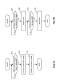
- FIG. 7A is a flowchart for describing one example of procedures for a connection status display process and a data save process executed by a control portion of an operation display device as in an embodiment of the present disclosure.
- FIG. 7B is a flowchart for describing one example of procedures for a connection status display process and a data save process executed by a control portion of an operation display device as in an embodiment of the present disclosure.
- FIG. 8A is a schematic view for describing an operation method on a display surface of an operation display device as in an embodiment of the present disclosure.
- FIG. 8B is a schematic view for describing an operation method on a display surface of an operation display device as in an embodiment of the present disclosure.
- FIG. 9 is a flowchart for describing one example of a procedure for an eject process executed by a control portion of an operation display device as in an embodiment of the preset disclosure.
- the following describes an operation display device 30 (one example of a display device of the present disclosure) as in an embodiment of the present disclosure, as well as an image forming apparatus 10 provided with the same (one example of an image forming apparatus of the present disclosure), with reference to the accompanying drawing as appropriate.
- the embodiment described below is merely one example embodying the present disclosure, and the embodiment of the present disclosure can be modified as appropriate within a scope not departing from the essence of the present disclosure.
- the image forming apparatus 10 is a so-called internal paper feed type, and is a multifunction peripheral provided with such functions as a printer function, a scanner function, a copier function, and a facsimile function.
- the image forming apparatus 10 uses a print material, such as a toner, for monochrome printing or color printing of an inputted image onto print paper.
- the image forming apparatus 10 is not limited to a multifunction peripheral; the present disclosure can also be applied to a dedicated apparatus such as a printer or a copier.
- the image forming apparatus 10 is provided at the top with a scanner 12 for reading in an image of a document, and is provided at the bottom with an electrophotographic image forming portion 14.
- the image forming portion 14 is not limited to electrophotographic, and may instead be of an inkjet recording system, or may be any other recording system or printing system.
- the scanner 12 is provided with a document loading surface 23.
- a read operation by the scanner 12 is initiated when copy start command is inputted from the operation display device 30 after a document has been placed at the document loading surface 23. Image data of the document is thereby read.
- FIG. 1 omits a depiction of a document cover for the scanner 12.
- the image forming portion 14 forms a monochrome image or color image on print paper of a defined size, such as the A series of sizes (for example, size A5, size A4, size A3) or the B series of sizes (for example, size B5 or size B4), on the basis of the image data read by the scanner 12 or of image data or text data that has been inputted from the exterior.
- the image forming portion 14 can also form a monochrome image or color image on print paper on the basis of image data or text data that has been read out directly from a USB memory 50A (see FIG. 4A ), an SD memory card 50B (see FIG. 5A ), or other form of external memory 50 (one example of an external storage device of the present disclosure) connected to the operation display device 30.
- the image forming portion 14 can also carry out a so-called direct print.
- a transfer device Provided to the bottom of the image forming portion 14 are two paper feed trays 16 able to hold a plurality of sheets of print paper.
- a transfer device Provided to the interior of the image forming portion 14 are a transfer device, a fixation device, a discharge portion, and the like (not shown).
- the transfer device transfers a toner image onto the fed print paper.
- the fixation device fixes the toner image to the print paper.
- the print paper, after fixation is then discharged by the discharge portion to a paper discharge space 21 provided to an upper side of the image forming portion 14.
- the operation display device 30 is provided to the right end of the front side of the scanner 12.
- the operation display device 30 is provided with a display panel 32 (see FIG. 2A ), an operation portion 34 (see FIG. 2A ), and a control portion 36 (see FIG. 3 ).
- the display panel 32 and the operation portion 34 are held within a case 31 (one example of a case of the present disclosure) of the operation display device 30.
- the display panel 32 is provided to an upper side (back side) of the operation display device 30.
- the display panel 32 is supported by the case 31 so that a display surface 32A thereof can be viewed by a user from the exterior.
- the display panel 32 displays information that relates to printing (a plurality of key images for input, settings, commands, and the like; a preview image of the image data or text data to be printed; a message indicative of the print status; or the like), by using liquid crystal.
- the display panel 32 also displays an image (hereinafter also "connector image”) of a connector, which is a connection portion of the external memory 50 (see FIG. 3 ) connected to the operation display device 30.
- the display panel 32 is a touch panel capable of detecting input by touch contact from the exterior, and, when a user touches a finger to contact the display surface 32A of the display panel 32, is capable of thereby accepting an input with respect to a displayed key image, the connector image, or the like.
- the operation portion 34 is provided to a bottom side (front side) of the operation display device 30.
- input keys such as: numeric keys 37 for inputting numbers 0 to 9 and the like; a start button 38 for starting up a print operation, software, or the like; and a stop button 39 for stopping a print operation or the like.
- the operation display device 30 is provided with the control portion 36.
- the control portion 36 has a CPU, ROM, RAM, ASIC, or the like, and, when software housed in the ROM is executed, or when a process according to an integrated circuit in the ASIC is carried out, thereby causes a predetermined image to be displayed on the display panel 32.
- the control portion 36 controls the operation display device 30 so as to carry out operations in accordance with a command input from the operation portion 34.
- the CPU of the control portion 36 reads and executes a software program housed in the ROM, a process according to the procedure illustrated by the flowcharts in FIGS. 7A, 7B and 9 is executed.
- the control portion 36 for executing such a process is an implementation of a connection determination portion, a display processing portion, a first input determination portion, a storage processing portion, a second input determination portion, and an erase processing portion of the present disclosure.
- a plurality of connection receiving portions 43 (43A to 43D) to which the external memory 50 is electrically connected are provided to one side surface 41 (in the present embodiment, the right side surface of the paper plane in FIG. 2A ) of the operation display device 30.
- the plurality of connection receiving portions 43 (43A to 43D) are portions to which external memories 50 of different standards are connected.
- a slot 43A into which the SD memory card 50B is inserted, a slot 43B into which a CompactFlash (registered trademark) is inserted, a slot 43C into which a Memory Stick (registered trademark) is inserted, and a USB connection portion 43D to which the USB memory 50A is connected are provided to the side surface 41.
- the external memories 50 inserted into the connection receiving portions 43 are each of different standards. For this reason, only the external memory 50 corresponding to the same connection receiving portion 43 can be connected thereto.
- the connection receiving portion 43 and a contact portion of the external memory 50 are electrically connected together, and the control portion 36 thereby recognizes the external memory 50.
- the SD memory card 50B, the CompactFlash (registered trademark), and the Memory Stick (registered trademark) are all examples of the card-type memory card of the present disclosure.
- a connector image 61 (connection portion image) indicative of a USB connector 55, which is a connection portion for the connected USB memory 50A, is displayed on the display surface 32A of the display panel 32 by the control portion 36.
- the control portion 36 determines whether or not the USB memory 50 has been connected to the USB connection portion 43D on the basis of whether or not there is an electrical connection between the USB connection portion 43D and the USB connector 55 (S11).
- the control portion 36 checks the electrical connection and determines that the USB memory 50A has been connected to the USB connection portion 43D
- the control portion 36 reads out the connector image 61 indicative of the USB connector 55 of the USB memory 50A from the ROM of the control portion 36 (S12). Thereafter, the control portion 36 displays the connector image 61 at a pre-established display position 65 on the display surface 32A (S13), as illustrated in FIG.
- the display position 65 is a position, on the display surface 32A of the display panel 32, that corresponds to the USB connection portion 43D to which the USB memory 50A is connected, and, as illustrated in FIG. 4B , is established at a position where an extension line of the direction of connection of the USB memory 50A and the right end of the display surface 32A intersect each other.
- a connector image 62 (connection portion image) indicative of a connection portion 56, which has a connection terminal for the inserted SD memory card 50B, is displayed on the display surface 32A of the display panel 32 by the control portion 36.
- a display position 66 at which the connector image 62 is displayed at this time is a position, on the display surface 32A of the display panel 32, that corresponds to the slot 43A into which the SD memory card 50B has been inserted.
- the display position of the connector image 62 as illustrated in FIG.
- the control portion 36 determines that an external contact has made a touch input (equivalent to the first input of the present disclosure) with respect to the connector image 61 (S21). In a case where a touch input is determined to have been made, the control portion 36 reads out relevant information (for example, header information for the data) indicative of the content of the data stored in the USB memory 50A, reads out the icon 69 associated with the data in the USB memory 50A from the ROM of the control portion 36, and displays the same at the display position 65 (S22). At this time, the icon 69 is displayed on the rear side of the connector image 61.
- relevant information for example, header information for the data
- the control portion 36 determines whether or not a command to save data has been inputted (S23). More specifically, when the user slides the finger in the same direction as the direction of connection of the USB memory 50A (hereinafter, "the first direction") while still touching the finger to the connector image 61, the control portion 36 determines that a continuous external input has been made in the first direction. In this case, the external input is recognized as a command to save data in the internal storage device 36A from the USB memory 50A. When the save command is determined to have been inputted, the control portion 36 moves, in the first direction, the icon 69 being displayed on the rear side of the connector image 61.
- the control portion 36 then reads out the data stored in the USB memory 50A and saves the same in the internal storage device 36A, such as a RAM, of the control portion 36 (S24).
- the control portion 36 also reads data from an external memory 50 and saves the same in the internal storage device 36A for the external memories 50 that are mounted onto the slots 43A to 43C, identically with respect to the case where data is read out from the USB memory 50A and saved.
- USB memory 50A This allows the user to store the data in the USB memory 50A into the internal storage device 36A merely by touching the connector image 61 and sliding in the first direction.
- data in the USB memory 50A can be easily stored in the internal storage device 36A without the need for user's cumbersome operation such as executing a plurality of operations in sequential order.
- the present disclosure may also be such that the control portion 36 stores the data in the USB memory 50A into the internal storage device 36A merely when the connector image 61 is touched for input.
- the control portion 36 may read out the image data from the image data deposit portion when the icon is moved by the user to the position of the connector image 61, and store the image data in the USB memory 50A. This makes it possible for the image data of the image data deposit portion to be easily stored in the USB memory 50A without the need for user's cumbersome operation such as carrying out a plurality of operations in sequential order.
- image data stored in an image data deposit portion (not shown), such as an HDD, provided to the image forming portion 14.
- image data include image data of a document read by the scanner 12, image data previously read out from an external memory 50 and saved, image data saved in the image data deposit portion externally via a wired or wireless connection, or the like. More specifically, when the user operates the operation portion 34 and selects the image data housed in the image data deposit portion, an icon indicative of the image data is displayed on the display surface 32A.
- the control portion 36 recognizes such an external input as a command to save data onto the USB memory 50A from the image data deposit portion. In a case where such an external input has been made, the control portion 36 reads out the image data from the image data deposit portion and stores the image data in the USB memory 50A, in a procedure inverse to the procedure for saving data onto the internal storage device 36A from the USB memory 50A.
- the control portion 36 erases the connector image 61 from the display surface 32A after the USB memory 50A enters a removable state.
- the control portion 36 determines whether or not a command to remove the USB memory 50A has been inputted, as illustrated in the flowchart in FIG. 9 (S31). More specifically, when the user slides a finger toward the connector image 61 (toward the right) while still touching the finger to a region further to the left than the connector image 61 of the display surface 32A, the control portion 36 determines that a continuous external input in a direction inverse to the direction of connection of the USB memory 50A (hereinafter, the "second direction") (equivalent to the second input of the present disclosure) has been made. The control portion 36 recognizes the external input as a command to remove the USB memory 50A.
- the second direction a continuous external input in a direction inverse to the direction of connection of the USB memory 50A
- the control portion 36 stops processes on the USB memory 50A and executes an eject process for placing the USB memory 50A into a removable state (S32). Thereafter, when the eject process is complete (S33), the control portion 36 erases the connector image 61 that had been displayed on the display surface 32A (S34).
- USB memory 50A This allows the user to place the USB memory 50A in a removable state, merely by executing the simple operation of sliding the finger in the second direction. Moreover, the erasure of the connector image 61 allows the user to easily recognize, in a sensory manner through vision, that the USB memory 50A is now in a removable state.
- the operation display device 30 is thus configured, when the USB memory 50A is connected to the USB connection portion 43D provided to the side surface 41 of the case 31 of the operation display device 30, the connector image 61 indicative of the USB connector 55 of the USB memory 50A is displayed at the display position 65 of the display surface 32A. It shall be readily understood that the connector image 61 is not displayed in a case where the USB memory 50A is not properly connected to the USB connection portion 43D. For this reason, even with a user not familiar with the connection operation for the USB memory 50A, the user can visually recognize whether or not the connector image 61 is being displayed on the display surface 32A.
- the user can also easily recognize that the USB memory 50A has actually been properly connected to the USB connection portion 43D, or that the USB memory 50A is not connected to the USB connection portion 43D. In this manner, the user can easily ascertain that the USB memory 50A has actually been connected merely by checking the connector image 61 displayed on the display surface 32A, without the need to carry out an operation following a plurality of cumbersome procedures. Also, because the user is notified of the connection status of the USB memory 50A merely by the connector image 61, there is no longer a need to prepare guidance comprising multilingual text, as in the prior art. It is also possible to eliminate the cumbersome operation of setting a guidance language for every country in which the image forming apparatus 10 is used.
- the icon 69 was displayed in a case where a touch input was applied to the connector image 61, but in a case where, for example, a plurality of sets of data are stored in the USB memory 50A, then when a touch input has been applied to the connector image 61, directory information on the data sets stored in the USB memory 50A may be displayed instead of the icon 69, and when a touch input is applied to one of the data sets in the directory information, an icon 69 associated with the data may be displayed. This makes it possible for only a data set selected from among a plurality of data sets to be read out from the USB memory 50A and stored in the internal storage device 36A.
Landscapes
- Engineering & Computer Science (AREA)
- Theoretical Computer Science (AREA)
- Multimedia (AREA)
- Signal Processing (AREA)
- General Engineering & Computer Science (AREA)
- Physics & Mathematics (AREA)
- General Physics & Mathematics (AREA)
- Human Computer Interaction (AREA)
- Accessory Devices And Overall Control Thereof (AREA)
- Controls And Circuits For Display Device (AREA)
- User Interface Of Digital Computer (AREA)
- Electrophotography Configuration And Component (AREA)
- Devices For Indicating Variable Information By Combining Individual Elements (AREA)
- Facsimiles In General (AREA)
Abstract
Description
- The present disclosure relates to a display device provided with a connection receiving portion to which an external storage device, such as a USB memory, is connected, and relates also to an image forming apparatus having a display panel.
- An image forming apparatus capable of printing after directly reading out data from an external storage device such as a USB memory or a memory card without the involvement of a cumbersome task such as migrating data to a personal computer (hereinafter, "computer"), has been known in recent years. Such a method of printing is called direct printing. An image forming apparatus capable of direct printing is provided with a connection receiving portion to which the external storage device can be connected. The image forming apparatus reads out data directly from the external storage device connected to the connection receiving portion. The image forming apparatus capable of direct printing is also provided with a display panel capable of displaying an image. The image forming apparatus is able to cause the display panel to display a preview image of the image data or text data that has been read out from the external storage device, before the printing is executed. This makes it possible for a user, in the process of executing a direct print, to select an image intended to be printed, crop the image, or check the image to be printed, while also consulting the preview image displayed on the display panel.
- The image forming apparatus capable of direct printing also displays, on the display panel, an operation guidance, such as guide information indicative of the correspondence relationship between the external storage device and the connection receiving portion or guide information indicative of the connection method or connection position for the external storage device, so as to enable the user to connect external storage devices of a variety of different standards, such as an SD memory card, Memory Stick (registered trademark), CompactFlash (registered trademark), SmartMedia (registered trademark), or USB memory.
- A display device as in one aspect of the present disclosure includes a display panel, a case, a connection receiving portion, a connection determination portion, and a display processing portion. The display panel displays an image. The case supports a display surface of the display panel so as to be viewable from the exterior. The connection receiving portion is provided to a side surface of the case, and electrically connects to an external storage device. The connection determination portion determines whether or not the external storage device has been connected to the connection receiving portion. The display processing portion displays, on the display panel, a connection portion image indicative of a connection portion of the connected external storage device in a case where the external storage device has been determined by the connection determination portion to have been connected.
- An image forming apparatus as in another aspect of the present disclosure includes a display panel, a case, a connection receiving portion, a connection determination portion, and a display processing portion. The display panel displays an image. The case supports a display surface of the display panel so as to be viewable from the exterior. The connection receiving portion is provided to a side surface of the case, and electrically connects to an external storage device. The connection determination portion determines whether or not the external storage device has been connected to the connection receiving portion. The display processing portion displays, on the display panel, a connection portion image indicative of a connection portion of the connected external storage device in a case where the external storage device has been determined by the connection determination portion to have been connected.
- This Summary is provided to introduce a selection of concepts in a simplified form that are further described below in the Detailed Description with reference where appropriate to the accompanying drawings. This Summary is not intended to identify key features or essential features of the claimed subject matter, nor is it intended to be used to limit the scope of the claimed subject matter. Furthermore, the claimed subject matter is not limited to implementations that solve any or all disadvantages noted in any part of this disclosure.
-
FIG. 1 is a perspective view illustrating a schematic configuration of an image forming apparatus as in an embodiment of the present disclosure. -
FIG. 2A is a schematic view illustrating a configuration of an operation display device as in an embodiment of the present disclosure. -
FIG. 2B is a schematic view illustrating a configuration of an operation display device as in an embodiment of the present disclosure. -
FIG. 3 is a block diagram illustrating a configuration of an operation display device as in an embodiment of the present disclosure. -
FIG. 4A is a schematic view for describing display content of a display surface of an operation display device as in an embodiment of the present disclosure. -
FIG. 4B is a schematic view for describing display content of a display surface of an operation display device as in an embodiment of the present disclosure. -
FIG. 5A is a schematic view for describing display content of a display surface of an operation display device as in an embodiment of the present disclosure. -
FIG. 5B is a schematic view for describing display content of a display surface of an operation display device as in an embodiment of the present disclosure. -
FIG. 6A is a schematic view for describing a method for a data save operation on a display surface of an operation display device as in an embodiment of the present disclosure. -
FIG. 6B is a schematic view for describing a method for a data save operation on a display surface of an operation display device as in an embodiment of the present disclosure. -
FIG. 7A is a flowchart for describing one example of procedures for a connection status display process and a data save process executed by a control portion of an operation display device as in an embodiment of the present disclosure. -
FIG. 7B is a flowchart for describing one example of procedures for a connection status display process and a data save process executed by a control portion of an operation display device as in an embodiment of the present disclosure. -
FIG. 8A is a schematic view for describing an operation method on a display surface of an operation display device as in an embodiment of the present disclosure. -
FIG. 8B is a schematic view for describing an operation method on a display surface of an operation display device as in an embodiment of the present disclosure. -
FIG. 9 is a flowchart for describing one example of a procedure for an eject process executed by a control portion of an operation display device as in an embodiment of the preset disclosure. - The following describes an operation display device 30 (one example of a display device of the present disclosure) as in an embodiment of the present disclosure, as well as an
image forming apparatus 10 provided with the same (one example of an image forming apparatus of the present disclosure), with reference to the accompanying drawing as appropriate. The embodiment described below is merely one example embodying the present disclosure, and the embodiment of the present disclosure can be modified as appropriate within a scope not departing from the essence of the present disclosure. - As illustrated in
FIG. 1 , theimage forming apparatus 10 is a so-called internal paper feed type, and is a multifunction peripheral provided with such functions as a printer function, a scanner function, a copier function, and a facsimile function. Theimage forming apparatus 10 uses a print material, such as a toner, for monochrome printing or color printing of an inputted image onto print paper. Theimage forming apparatus 10 is not limited to a multifunction peripheral; the present disclosure can also be applied to a dedicated apparatus such as a printer or a copier. - The
image forming apparatus 10 is provided at the top with ascanner 12 for reading in an image of a document, and is provided at the bottom with an electrophotographicimage forming portion 14. Theimage forming portion 14 is not limited to electrophotographic, and may instead be of an inkjet recording system, or may be any other recording system or printing system. - As illustrated in
FIG. 1 , thescanner 12 is provided with adocument loading surface 23. In a case where theimage forming apparatus 10 functions as a copier, a read operation by thescanner 12 is initiated when copy start command is inputted from theoperation display device 30 after a document has been placed at thedocument loading surface 23. Image data of the document is thereby read.FIG. 1 omits a depiction of a document cover for thescanner 12. - The
image forming portion 14 forms a monochrome image or color image on print paper of a defined size, such as the A series of sizes (for example, size A5, size A4, size A3) or the B series of sizes (for example, size B5 or size B4), on the basis of the image data read by thescanner 12 or of image data or text data that has been inputted from the exterior.
Theimage forming portion 14 can also form a monochrome image or color image on print paper on the basis of image data or text data that has been read out directly from aUSB memory 50A (seeFIG. 4A ), anSD memory card 50B (seeFIG. 5A ), or other form of external memory 50 (one example of an external storage device of the present disclosure) connected to theoperation display device 30. In other words, theimage forming portion 14 can also carry out a so-called direct print. - Provided to the bottom of the
image forming portion 14 are twopaper feed trays 16 able to hold a plurality of sheets of print paper. Provided to the interior of theimage forming portion 14 are a transfer device, a fixation device, a discharge portion, and the like (not shown). When print paper is fed from thepaper feed trays 16 to the transfer device,
the transfer device transfers a toner image onto the fed print paper. Thereafter, the fixation device fixes the toner image to the print paper. The print paper, after fixation, is then discharged by the discharge portion to apaper discharge space 21 provided to an upper side of theimage forming portion 14. - The
operation display device 30 is provided to the right end of the front side of thescanner 12. Theoperation display device 30 is provided with a display panel 32 (seeFIG. 2A ), an operation portion 34 (seeFIG. 2A ), and a control portion 36 (seeFIG. 3 ). Thedisplay panel 32 and theoperation portion 34 are held within a case 31 (one example of a case of the present disclosure) of theoperation display device 30. - As illustrated in
FIG. 2A , thedisplay panel 32 is provided to an upper side (back side) of theoperation display device 30. Thedisplay panel 32 is supported by thecase 31 so that adisplay surface 32A thereof can be viewed by a user from the exterior. Thedisplay panel 32 displays information that relates to printing (a plurality of key images for input, settings, commands, and the like; a preview image of the image data or text data to be printed; a message indicative of the print status; or the like), by using liquid crystal. As will be described below, thedisplay panel 32 also displays an image (hereinafter also "connector image") of a connector, which is a connection portion of the external memory 50 (seeFIG. 3 ) connected to theoperation display device 30. Thedisplay panel 32 is a touch panel capable of detecting input by touch contact from the exterior, and, when a user touches a finger to contact thedisplay surface 32A of thedisplay panel 32, is capable of thereby accepting an input with respect to a displayed key image, the connector image, or the like. - As illustrated in
FIG. 2A , theoperation portion 34 is provided to a bottom side (front side) of theoperation display device 30. Arranged on anupper surface 34A of theoperation portion 34 are input keys, such as:numeric keys 37 for inputtingnumbers 0 to 9 and the like; astart button 38 for starting up a print operation, software, or the like; and astop button 39 for stopping a print operation or the like. - As illustrated in
FIG. 3 , theoperation display device 30 is provided with thecontrol portion 36. Thecontrol portion 36 has a CPU, ROM, RAM, ASIC, or the like, and, when software housed in the ROM is executed, or when a process according to an integrated circuit in the ASIC is carried out, thereby causes a predetermined image to be displayed on thedisplay panel 32. In other words, thecontrol portion 36 controls theoperation display device 30 so as to carry out operations in accordance with a command input from theoperation portion 34. In the present embodiment, when the CPU of thecontrol portion 36 reads and executes a software program housed in the ROM, a process according to the procedure illustrated by the flowcharts inFIGS. 7A, 7B and9 is executed. Thecontrol portion 36 for executing such a process is an implementation of a connection determination portion, a display processing portion, a first input determination portion, a storage processing portion, a second input determination portion, and an erase processing portion of the present disclosure. - As illustrated in FIG. 2E, a plurality of connection receiving portions 43 (43A to 43D) to which the
external memory 50 is electrically connected are provided to one side surface 41 (in the present embodiment, the right side surface of the paper plane inFIG. 2A ) of theoperation display device 30. The plurality of connection receiving portions 43 (43A to 43D) are portions to whichexternal memories 50 of different standards are connected. In the present embodiment, aslot 43A into which theSD memory card 50B is inserted, aslot 43B into which a CompactFlash (registered trademark) is inserted, aslot 43C into which a Memory Stick (registered trademark) is inserted, and aUSB connection portion 43D to which theUSB memory 50A is connected are provided to theside surface 41. Theexternal memories 50 inserted into theconnection receiving portions 43 are each of different standards. For this reason, only theexternal memory 50 corresponding to the sameconnection receiving portion 43 can be connected thereto. When anexternal memory 50 is connected to aconnection receiving portion 43, theconnection receiving portion 43 and a contact portion of theexternal memory 50 are electrically connected together, and thecontrol portion 36 thereby recognizes theexternal memory 50. Herein, theSD memory card 50B, the CompactFlash (registered trademark), and the Memory Stick (registered trademark) are all examples of the card-type memory card of the present disclosure. - In the present embodiment, as illustrated in
FIG. 4B , when theUSB memory 50A is connected to theUSB connection portion 43D, a connector image 61 (connection portion image) indicative of aUSB connector 55, which is a connection portion for theconnected USB memory 50A, is displayed on thedisplay surface 32A of thedisplay panel 32 by thecontrol portion 36. - More specifically, as illustrated in the flowchart in
FIG. 7A , when theUSB memory 50A is connected to theUSB connection portion 43D, thecontrol portion 36 determines whether or not theUSB memory 50 has been connected to theUSB connection portion 43D on the basis of whether or not there is an electrical connection between theUSB connection portion 43D and the USB connector 55 (S11). Herein, when thecontrol portion 36 checks the electrical connection and determines that theUSB memory 50A has been connected to theUSB connection portion 43D, thecontrol portion 36 reads out theconnector image 61 indicative of theUSB connector 55 of theUSB memory 50A from the ROM of the control portion 36 (S12). Thereafter, thecontrol portion 36 displays theconnector image 61 at apre-established display position 65 on thedisplay surface 32A (S13), as illustrated inFIG. 4B . Thedisplay position 65 is a position, on thedisplay surface 32A of thedisplay panel 32, that corresponds to theUSB connection portion 43D to which theUSB memory 50A is connected, and, as illustrated inFIG. 4B , is established at a position where an extension line of the direction of connection of theUSB memory 50A and the right end of thedisplay surface 32A intersect each other. - As illustrated in
FIG. 5B , in a case where theSD memory card 50B is inserted into theslot 43A, identically with respect to the case where theUSB memory 50A is connected to theUSB connection portion 43D, a connector image 62 (connection portion image) indicative of aconnection portion 56, which has a connection terminal for the insertedSD memory card 50B, is displayed on thedisplay surface 32A of thedisplay panel 32 by thecontrol portion 36. Adisplay position 66 at which theconnector image 62 is displayed at this time is a position, on thedisplay surface 32A of thedisplay panel 32, that corresponds to theslot 43A into which theSD memory card 50B has been inserted. The display position of theconnector image 62, as illustrated inFIG. 5B , is established at a position where an extension line of the direction of insertion of theSD memory card 50B and the right end of thedisplay surface 32A intersect each other. In a case where anexternal memory 50 is connected to theslot 43B or theslot 43C, too, identically with respect to the case where theUSB memory 50A is connected to theUSB connection portion 43D, a connector image for theexternal memory 50 is displayed at a position corresponding to theslot 43B or theslot 43C. - In this manner, in cases where the
external memories 50 are connected respectively to the plurality of connection receiving portions 43 (43A to 43D) provided to theside surface 41 of thecase 31, images for the connection portions, such as theconnector image 61 or theconnector image 62, are displayed at positions corresponding to each of the connection receiving portions 43 (43A to 43D). This allows the user to intuitively recognize the position of theexternal memory 50 that has been connected by the user, as well as to recognize that theexternal memory 50 has actually been correctly connected. - In the present embodiment, as illustrated in
FIG. 6A , when the user touches theconnector image 61 for theUSB memory 50A displayed on thedisplay surface 32A with a finger, anicon 69 indicative of data stored in theUSB memory 50A is displayed by thecontrol portion 36. Then, when the user slides the finger in the same direction as the direction of connection of theUSB memory 50A while still touching the finger to theconnector image 61 so as to move theicon 69 on thedisplay surface 32A, the data stored in theUSB memory 50A is read out by thecontrol portion 36. Thereafter, the data thus read is stored in aninternal storage device 36A, such as a RAM, that is built into thecontrol portion 36. - More specifically, as illustrated in the flowchart in
FIG. 7B , when the user touches a finger to theconnector image 61 being displayed on thedisplay surface 32A, thecontrol portion 36 determines that an external contact has made a touch input (equivalent to the first input of the present disclosure) with respect to the connector image 61 (S21). In a case where a touch input is determined to have been made, thecontrol portion 36 reads out relevant information (for example, header information for the data) indicative of the content of the data stored in theUSB memory 50A, reads out theicon 69 associated with the data in theUSB memory 50A from the ROM of thecontrol portion 36, and displays the same at the display position 65 (S22). At this time, theicon 69 is displayed on the rear side of theconnector image 61. Next, thecontrol portion 36 determines whether or not a command to save data has been inputted (S23). More specifically, when the user slides the finger in the same direction as the direction of connection of theUSB memory 50A (hereinafter, "the first direction") while still touching the finger to theconnector image 61, thecontrol portion 36 determines that a continuous external input has been made in the first direction. In this case, the external input is recognized as a command to save data in theinternal storage device 36A from theUSB memory 50A. When the save command is determined to have been inputted, thecontrol portion 36 moves, in the first direction, theicon 69 being displayed on the rear side of theconnector image 61. Thecontrol portion 36 then reads out the data stored in theUSB memory 50A and saves the same in theinternal storage device 36A, such as a RAM, of the control portion 36 (S24). Thecontrol portion 36 also reads data from anexternal memory 50 and saves the same in theinternal storage device 36A for theexternal memories 50 that are mounted onto theslots 43A to 43C, identically with respect to the case where data is read out from theUSB memory 50A and saved. - This allows the user to store the data in the
USB memory 50A into theinternal storage device 36A merely by touching theconnector image 61 and sliding in the first direction. As a result, with a single touch, data in theUSB memory 50A can be easily stored in theinternal storage device 36A without the need for user's cumbersome operation such as executing a plurality of operations in sequential order. The present disclosure may also be such that thecontrol portion 36 stores the data in theUSB memory 50A into theinternal storage device 36A merely when theconnector image 61 is touched for input. In a configuration in which, for example, thecontrol portion 36 causes thedisplay surface 32A to display an icon indicative of image data stored in an image data deposit portion (not shown) inside theimage forming portion 14 when the user selects the image data, thecontrol portion 36 may read out the image data from the image data deposit portion when the icon is moved by the user to the position of theconnector image 61, and store the image data in theUSB memory 50A. This makes it possible for the image data of the image data deposit portion to be easily stored in theUSB memory 50A without the need for user's cumbersome operation such as carrying out a plurality of operations in sequential order. - In the present embodiment, it would also be possible to easily save, into the
USB memory 50A, image data stored in an image data deposit portion (not shown), such as an HDD, provided to theimage forming portion 14. Examples of such types of image data include image data of a document read by thescanner 12, image data previously read out from anexternal memory 50 and saved, image data saved in the image data deposit portion externally via a wired or wireless connection, or the like. More specifically, when the user operates theoperation portion 34 and selects the image data housed in the image data deposit portion, an icon indicative of the image data is displayed on thedisplay surface 32A. Then, when the user slides the finger to the position of theconnector image 61 while still touching the finger to the icon so as to move the icon on thedisplay surface 32A, the icon moves to the position of theconnector image 61. Thecontrol portion 36 recognizes such an external input as a command to save data onto theUSB memory 50A from the image data deposit portion. In a case where such an external input has been made, thecontrol portion 36 reads out the image data from the image data deposit portion and stores the image data in theUSB memory 50A, in a procedure inverse to the procedure for saving data onto theinternal storage device 36A from theUSB memory 50A. - In the present embodiment, as illustrated in
FIGS. 8A, 8B , in a case where a continuous external input has been made in one direction in the vicinity of theconnector image 61 of theUSB memory 50A displayed on thedisplay surface 32A, then thecontrol portion 36 erases theconnector image 61 from thedisplay surface 32A after theUSB memory 50A enters a removable state. - More specifically, the
control portion 36 determines whether or not a command to remove theUSB memory 50A has been inputted, as illustrated in the flowchart inFIG. 9 (S31). More specifically, when the user slides a finger toward the connector image 61 (toward the right) while still touching the finger to a region further to the left than theconnector image 61 of thedisplay surface 32A, thecontrol portion 36 determines that a continuous external input in a direction inverse to the direction of connection of theUSB memory 50A (hereinafter, the "second direction") (equivalent to the second input of the present disclosure) has been made. Thecontrol portion 36 recognizes the external input as a command to remove theUSB memory 50A. When a remove command is determined to have been inputted, thecontrol portion 36 stops processes on theUSB memory 50A and executes an eject process for placing theUSB memory 50A into a removable state (S32). Thereafter, when the eject process is complete (S33), thecontrol portion 36 erases theconnector image 61 that had been displayed on thedisplay surface 32A (S34). - This allows the user to place the
USB memory 50A in a removable state, merely by executing the simple operation of sliding the finger in the second direction. Moreover, the erasure of theconnector image 61 allows the user to easily recognize, in a sensory manner through vision, that theUSB memory 50A is now in a removable state. - Because the
operation display device 30 is thus configured, when theUSB memory 50A is connected to theUSB connection portion 43D provided to theside surface 41 of thecase 31 of theoperation display device 30, theconnector image 61 indicative of theUSB connector 55 of theUSB memory 50A is displayed at thedisplay position 65 of thedisplay surface 32A. It shall be readily understood that theconnector image 61 is not displayed in a case where theUSB memory 50A is not properly connected to theUSB connection portion 43D. For this reason, even with a user not familiar with the connection operation for theUSB memory 50A, the user can visually recognize whether or not theconnector image 61 is being displayed on thedisplay surface 32A. The user can also easily recognize that theUSB memory 50A has actually been properly connected to theUSB connection portion 43D, or that theUSB memory 50A is not connected to theUSB connection portion 43D. In this manner, the user can easily ascertain that theUSB memory 50A has actually been connected merely by checking theconnector image 61 displayed on thedisplay surface 32A, without the need to carry out an operation following a plurality of cumbersome procedures. Also, because the user is notified of the connection status of theUSB memory 50A merely by theconnector image 61, there is no longer a need to prepare guidance comprising multilingual text, as in the prior art. It is also possible to eliminate the cumbersome operation of setting a guidance language for every country in which theimage forming apparatus 10 is used. - In the embodiment described above, the
icon 69 was displayed in a case where a touch input was applied to theconnector image 61, but in a case where, for example, a plurality of sets of data are stored in theUSB memory 50A, then when a touch input has been applied to theconnector image 61, directory information on the data sets stored in theUSB memory 50A may be displayed instead of theicon 69, and when a touch input is applied to one of the data sets in the directory information, anicon 69 associated with the data may be displayed. This makes it possible for only a data set selected from among a plurality of data sets to be read out from theUSB memory 50A and stored in theinternal storage device 36A. - It is to be understood that the embodiments herein are illustrative and not restrictive, since the scope of the invention is defined by the appended claims rather than by the description preceding them, and all changes that fall within metes and bounds of the claims, or equivalence of such metes and bounds thereof are therefore intended to be embraced by the claims.
Claims (6)
- A display device(30), comprising:a display panel(32) that displays an image;a case(31) that supports a display surface of the display panel(32) so as to be visible from the exterior;a connection receiving portion(43,43A-43D) that electrically connects to an external storage device(50,50A,50B), the connection receiving portion(43,43A-43D) being provided to a side surface of the case(31);a connection determination portion(36) that determines whether or not the external storage device(50,50A,50B) has been connected to the connection receiving portion(43,43A-43D); anda display processing portion(36) that displays, on the display panel(32), a connection portion image(61,62) indicative of a connection portion of the connected external storage device(50,50A,50B) in a case(31) where the external storage device(50,50A,50B) has been determined by the connection determination portion(36) to be connected.
- The display device(30) according to claim 1, wherein:a plurality of the connection receiving portions(43,43A-43D) each respectively corresponding to a plurality of types of the external storage device(50,50A,50B) are provided to the side surface of the case(31); andthe display processing portion(36) causes the display panel(32) to display the connection portion image(61,62) at a position corresponding to the connection receiving portion(43,43A-43D) to which the external storage device is connected.
- The display device(30) according to claim 1 or 2, wherein:the display panel(32) is a touch panel capable of detecting an input by an external contact;and the display device(32) is further provided with: a first input determination portion(36) that determines whether or not a predetermined first input by external contact has been made at a display position of the connection portion image(61,62) on the display panel(32);an internal storage device(36A) provided to the interior of the display device(30); anda storage processing portion(36) that reads out and stores, in the internal storage device(36A), data stored in the external storage device(50,50A,50B) in a case where the first input has been determined by the first input determination portion(36) to have been made.
- The display device(30) according to claim 1 or 2, wherein:the display panel(32) is a touch panel capable of detecting an input by an external contact;and the display device(32) is further provided with: a second input determination portion(36) that determines whether or not a second input by continuous external contact has been made in one direction in the vicinity of a display position of the connection portion image(61,62) on the display panel(32); andan erase processing portion(36) that erases the connection portion image(61,62) from the display panel(32) after the external storage device(50,50A,50B) has been placed in a removable state in a case where the second input has been determined by the second input determination portion(36) to have been made.
- The display device(30) according to any one of claims 1 to 4, wherein the external storage device(50,50A,50B) is a USB memory(50A) having a USB connector, or is a card-type memory card(50B).
- An image forming apparatus(10) comprising:the display device(30) according to any one of claims 1 to 5.
Applications Claiming Priority (1)
| Application Number | Priority Date | Filing Date | Title |
|---|---|---|---|
| JP2012100792A JP5649611B2 (en) | 2012-04-26 | 2012-04-26 | Display device and image forming apparatus having the same |
Publications (3)
| Publication Number | Publication Date |
|---|---|
| EP2658237A2 true EP2658237A2 (en) | 2013-10-30 |
| EP2658237A3 EP2658237A3 (en) | 2013-11-06 |
| EP2658237B1 EP2658237B1 (en) | 2018-05-23 |
Family
ID=48128211
Family Applications (1)
| Application Number | Title | Priority Date | Filing Date |
|---|---|---|---|
| EP13164497.3A Not-in-force EP2658237B1 (en) | 2012-04-26 | 2013-04-19 | Display device having connection receiving portion for external storage device and image forming apparatus having display panel |
Country Status (5)
| Country | Link |
|---|---|
| US (1) | US9026690B2 (en) |
| EP (1) | EP2658237B1 (en) |
| JP (1) | JP5649611B2 (en) |
| KR (1) | KR101474120B1 (en) |
| CN (1) | CN103379245B (en) |
Families Citing this family (6)
| Publication number | Priority date | Publication date | Assignee | Title |
|---|---|---|---|---|
| CN103853679B (en) * | 2012-11-30 | 2016-08-31 | 纬创资通股份有限公司 | Setting method of peripheral device removal interface and electronic device |
| JP6100062B2 (en) * | 2013-04-01 | 2017-03-22 | キヤノン株式会社 | Printing apparatus, control method, program |
| CN105373499B (en) * | 2014-08-29 | 2018-12-21 | 昆山纬绩资通有限公司 | The method and computer system of removal external equipment and non-transient readable medium |
| JP6857047B2 (en) * | 2017-02-20 | 2021-04-14 | キヤノン株式会社 | Image forming device, display method and program |
| JP7132872B2 (en) * | 2019-02-26 | 2022-09-07 | シャープ株式会社 | MFP |
| JP7180460B2 (en) * | 2019-03-07 | 2022-11-30 | ブラザー工業株式会社 | Document reading device and image forming device |
Family Cites Families (28)
| Publication number | Priority date | Publication date | Assignee | Title |
|---|---|---|---|---|
| US6473811B1 (en) * | 1998-03-13 | 2002-10-29 | Canon Kabushiki Kaisha | Method and apparatus for displaying a connection status of a device based on connection information |
| JP2002222391A (en) * | 2001-01-29 | 2002-08-09 | Matsushita Electric Ind Co Ltd | Memory card management device and memory card management method |
| JP2004054879A (en) * | 2002-05-27 | 2004-02-19 | Sony Corp | Display device and display method |
| JP2005004445A (en) * | 2003-06-11 | 2005-01-06 | Sony Corp | Information processing apparatus and information processing method |
| US6993618B2 (en) * | 2004-01-15 | 2006-01-31 | Super Talent Electronics, Inc. | Dual-mode flash storage exchanger that transfers flash-card data to a removable USB flash key-drive with or without a PC host |
| JP2006180324A (en) | 2004-12-24 | 2006-07-06 | Funai Electric Co Ltd | Digital multifunctional device and printer device |
| JP2008171099A (en) * | 2007-01-10 | 2008-07-24 | Yokogawa Electric Corp | Display device using touch panel |
| KR20080074325A (en) * | 2007-02-08 | 2008-08-13 | 삼성전자주식회사 | Image forming apparatus with built-in viewer and control method |
| JP4425940B2 (en) * | 2007-03-09 | 2010-03-03 | シャープ株式会社 | Image data processing device |
| JP4518095B2 (en) * | 2007-03-30 | 2010-08-04 | ブラザー工業株式会社 | Image forming apparatus |
| JP2008257442A (en) * | 2007-04-04 | 2008-10-23 | Sharp Corp | Electronic bulletin board |
| US20090024769A1 (en) | 2007-05-08 | 2009-01-22 | Atsuhito Nakatani | Operating device for electronic equipment, operating system, image processing apparatus, information display apparatus, and external equipment connecting device |
| JP2009021948A (en) * | 2007-07-13 | 2009-01-29 | Konica Minolta Business Technologies Inc | Image forming apparatus |
| JP2009134512A (en) | 2007-11-30 | 2009-06-18 | Brother Ind Ltd | Information processing apparatus and information processing program |
| JP4407748B2 (en) * | 2007-12-21 | 2010-02-03 | ソニー株式会社 | Imaging apparatus, communication control method, and program |
| JP4466739B2 (en) * | 2008-01-15 | 2010-05-26 | コニカミノルタビジネステクノロジーズ株式会社 | Image forming apparatus |
| JP4524316B2 (en) * | 2008-01-30 | 2010-08-18 | 株式会社沖データ | Image processing apparatus and image processing system |
| US8028244B2 (en) * | 2008-02-21 | 2011-09-27 | Brother Kogyo Kabushiki Kaisha | Status processing system, status processor, and status displaying method |
| JP4637203B2 (en) * | 2008-04-22 | 2011-02-23 | シャープ株式会社 | Information processing apparatus, multifunction device, external authentication system for multifunction device, program, and recording medium |
| CN101763328B (en) * | 2008-12-25 | 2014-01-15 | 鸿富锦精密工业(深圳)有限公司 | Data transmission system and method thereof |
| US8214550B2 (en) * | 2009-03-22 | 2012-07-03 | Silicon Motion Inc. | Method for controlling icon display corresponding to a USB mass storage, associated personal computer, and storage medium storing an associated USB mass storage driver |
| JP5177071B2 (en) * | 2009-04-30 | 2013-04-03 | ソニー株式会社 | Transmitting apparatus and method, receiving apparatus and method, and transmission / reception system |
| KR20110072879A (en) * | 2009-12-23 | 2011-06-29 | 삼성전자주식회사 | Image forming apparatus, host apparatus and control method of host apparatus |
| JP2011248733A (en) * | 2010-05-28 | 2011-12-08 | Nikon Corp | Electronic apparatus |
| JP5325862B2 (en) * | 2010-09-28 | 2013-10-23 | 京セラドキュメントソリューションズ株式会社 | Image forming apparatus and data storage program |
| JP2012099454A (en) * | 2010-10-08 | 2012-05-24 | Sony Corp | Portable information processing device |
| JP5606293B2 (en) * | 2010-11-22 | 2014-10-15 | キヤノン株式会社 | Data processing apparatus, access control method and program |
| JP5741048B2 (en) * | 2011-02-21 | 2015-07-01 | 株式会社リコー | Image forming apparatus, authentication program, and storage medium |
-
2012
- 2012-04-26 JP JP2012100792A patent/JP5649611B2/en not_active Expired - Fee Related
-
2013
- 2013-04-16 KR KR1020130041602A patent/KR101474120B1/en not_active Expired - Fee Related
- 2013-04-18 US US13/865,923 patent/US9026690B2/en not_active Expired - Fee Related
- 2013-04-19 EP EP13164497.3A patent/EP2658237B1/en not_active Not-in-force
- 2013-04-22 CN CN201310141486.6A patent/CN103379245B/en not_active Expired - Fee Related
Non-Patent Citations (1)
| Title |
|---|
| None |
Also Published As
| Publication number | Publication date |
|---|---|
| KR101474120B1 (en) | 2014-12-17 |
| JP2013228911A (en) | 2013-11-07 |
| EP2658237B1 (en) | 2018-05-23 |
| KR20130121022A (en) | 2013-11-05 |
| JP5649611B2 (en) | 2015-01-07 |
| US9026690B2 (en) | 2015-05-05 |
| US20130290576A1 (en) | 2013-10-31 |
| EP2658237A3 (en) | 2013-11-06 |
| CN103379245B (en) | 2015-12-09 |
| CN103379245A (en) | 2013-10-30 |
Similar Documents
| Publication | Publication Date | Title |
|---|---|---|
| EP2658237B1 (en) | Display device having connection receiving portion for external storage device and image forming apparatus having display panel | |
| US9122329B2 (en) | Image displaying apparatus, image controlling apparatus, image forming apparatus, image controlling method, and computer-readable medium | |
| US10277757B2 (en) | Electronic device and image forming apparatus | |
| US20110050544A1 (en) | Image display system including a plurality of electronic paper display devices | |
| EP2026194A2 (en) | Image forming apparatus | |
| EP3016366A1 (en) | Desktop information processing apparatus and printing method thereof | |
| US9025173B2 (en) | Image display apparatus for display of a plurality of images | |
| EP2541330A2 (en) | Printing apparatus | |
| US20160316080A1 (en) | Image Forming System That Moves Print Job between a Plurality of Image Forming Apparatuses and Recording Medium | |
| US10924616B2 (en) | Image processing apparatus, image processing method, and non-transitory storage medium storing instructions executable by the image processing apparatus having a shortcut function | |
| US20180091671A1 (en) | Image Reading Apparatus and Image Reading Method That Simply Detect Document Direction in Reading of Book Document, and Recording Medium Therefor | |
| JP6035318B2 (en) | Display input device and image forming apparatus having the same | |
| JP5919239B2 (en) | Display input device, image forming apparatus | |
| JP2009188486A (en) | Display device and display method | |
| US10270932B2 (en) | Non-transitory computer-readable medium and portable device | |
| JP2008187668A (en) | Image forming apparatus | |
| JP2015028733A (en) | Operation device and image processing apparatus | |
| US12118208B2 (en) | Display apparatus that displays menu item indicating name of group including item to be set displayed at uppermost position of scrollable display region, in different display style from other menu items, and image forming apparatus | |
| JP6165519B2 (en) | Image forming apparatus | |
| JP6939027B2 (en) | Display control device, image processing device, display control method and display control program | |
| US9924053B2 (en) | Setting method and setting apparatus of image forming apparatus | |
| US20210329136A1 (en) | Information processing apparatus capable of allowing display device to display combinations of setting values satisfying predetermined condition | |
| CN113635682A (en) | Printing control device and control method for printing with paper insertion function | |
| JP4680217B2 (en) | Image forming apparatus | |
| US20240131855A1 (en) | Printing apparatus capable of guiding and displaying initial installation, control method therefor and storage medium |
Legal Events
| Date | Code | Title | Description |
|---|---|---|---|
| PUAL | Search report despatched |
Free format text: ORIGINAL CODE: 0009013 |
|
| PUAI | Public reference made under article 153(3) epc to a published international application that has entered the european phase |
Free format text: ORIGINAL CODE: 0009012 |
|
| AK | Designated contracting states |
Kind code of ref document: A2 Designated state(s): AL AT BE BG CH CY CZ DE DK EE ES FI FR GB GR HR HU IE IS IT LI LT LU LV MC MK MT NL NO PL PT RO RS SE SI SK SM TR |
|
| AX | Request for extension of the european patent |
Extension state: BA ME |
|
| AK | Designated contracting states |
Kind code of ref document: A3 Designated state(s): AL AT BE BG CH CY CZ DE DK EE ES FI FR GB GR HR HU IE IS IT LI LT LU LV MC MK MT NL NO PL PT RO RS SE SI SK SM TR |
|
| AX | Request for extension of the european patent |
Extension state: BA ME |
|
| RIC1 | Information provided on ipc code assigned before grant |
Ipc: H04N 1/00 20060101AFI20131001BHEP |
|
| 17P | Request for examination filed |
Effective date: 20140428 |
|
| RBV | Designated contracting states (corrected) |
Designated state(s): AL AT BE BG CH CY CZ DE DK EE ES FI FR GB GR HR HU IE IS IT LI LT LU LV MC MK MT NL NO PL PT RO RS SE SI SK SM TR |
|
| 17Q | First examination report despatched |
Effective date: 20141106 |
|
| REG | Reference to a national code |
Ref country code: DE Ref legal event code: R079 Ref document number: 602013037731 Country of ref document: DE Free format text: PREVIOUS MAIN CLASS: H04N0001000000 Ipc: G06F0013100000 |
|
| GRAP | Despatch of communication of intention to grant a patent |
Free format text: ORIGINAL CODE: EPIDOSNIGR1 |
|
| STAA | Information on the status of an ep patent application or granted ep patent |
Free format text: STATUS: GRANT OF PATENT IS INTENDED |
|
| RIC1 | Information provided on ipc code assigned before grant |
Ipc: G06F 13/10 20060101AFI20180123BHEP Ipc: H04N 1/00 20060101ALI20180123BHEP |
|
| INTG | Intention to grant announced |
Effective date: 20180223 |
|
| RIN1 | Information on inventor provided before grant (corrected) |
Inventor name: SHIGENOBU, DAI |
|
| GRAS | Grant fee paid |
Free format text: ORIGINAL CODE: EPIDOSNIGR3 |
|
| GRAA | (expected) grant |
Free format text: ORIGINAL CODE: 0009210 |
|
| STAA | Information on the status of an ep patent application or granted ep patent |
Free format text: STATUS: THE PATENT HAS BEEN GRANTED |
|
| AK | Designated contracting states |
Kind code of ref document: B1 Designated state(s): AL AT BE BG CH CY CZ DE DK EE ES FI FR GB GR HR HU IE IS IT LI LT LU LV MC MK MT NL NO PL PT RO RS SE SI SK SM TR |
|
| REG | Reference to a national code |
Ref country code: GB Ref legal event code: FG4D |
|
| REG | Reference to a national code |
Ref country code: CH Ref legal event code: EP |
|
| REG | Reference to a national code |
Ref country code: IE Ref legal event code: FG4D |
|
| REG | Reference to a national code |
Ref country code: AT Ref legal event code: REF Ref document number: 1002063 Country of ref document: AT Kind code of ref document: T Effective date: 20180615 |
|
| REG | Reference to a national code |
Ref country code: DE Ref legal event code: R096 Ref document number: 602013037731 Country of ref document: DE |
|
| REG | Reference to a national code |
Ref country code: NL Ref legal event code: MP Effective date: 20180523 |
|
| REG | Reference to a national code |
Ref country code: LT Ref legal event code: MG4D |
|
| PG25 | Lapsed in a contracting state [announced via postgrant information from national office to epo] |
Ref country code: BG Free format text: LAPSE BECAUSE OF FAILURE TO SUBMIT A TRANSLATION OF THE DESCRIPTION OR TO PAY THE FEE WITHIN THE PRESCRIBED TIME-LIMIT Effective date: 20180823 Ref country code: FI Free format text: LAPSE BECAUSE OF FAILURE TO SUBMIT A TRANSLATION OF THE DESCRIPTION OR TO PAY THE FEE WITHIN THE PRESCRIBED TIME-LIMIT Effective date: 20180523 Ref country code: NO Free format text: LAPSE BECAUSE OF FAILURE TO SUBMIT A TRANSLATION OF THE DESCRIPTION OR TO PAY THE FEE WITHIN THE PRESCRIBED TIME-LIMIT Effective date: 20180823 Ref country code: SE Free format text: LAPSE BECAUSE OF FAILURE TO SUBMIT A TRANSLATION OF THE DESCRIPTION OR TO PAY THE FEE WITHIN THE PRESCRIBED TIME-LIMIT Effective date: 20180523 Ref country code: LT Free format text: LAPSE BECAUSE OF FAILURE TO SUBMIT A TRANSLATION OF THE DESCRIPTION OR TO PAY THE FEE WITHIN THE PRESCRIBED TIME-LIMIT Effective date: 20180523 Ref country code: ES Free format text: LAPSE BECAUSE OF FAILURE TO SUBMIT A TRANSLATION OF THE DESCRIPTION OR TO PAY THE FEE WITHIN THE PRESCRIBED TIME-LIMIT Effective date: 20180523 |
|
| PG25 | Lapsed in a contracting state [announced via postgrant information from national office to epo] |
Ref country code: GR Free format text: LAPSE BECAUSE OF FAILURE TO SUBMIT A TRANSLATION OF THE DESCRIPTION OR TO PAY THE FEE WITHIN THE PRESCRIBED TIME-LIMIT Effective date: 20180824 Ref country code: HR Free format text: LAPSE BECAUSE OF FAILURE TO SUBMIT A TRANSLATION OF THE DESCRIPTION OR TO PAY THE FEE WITHIN THE PRESCRIBED TIME-LIMIT Effective date: 20180523 Ref country code: NL Free format text: LAPSE BECAUSE OF FAILURE TO SUBMIT A TRANSLATION OF THE DESCRIPTION OR TO PAY THE FEE WITHIN THE PRESCRIBED TIME-LIMIT Effective date: 20180523 Ref country code: LV Free format text: LAPSE BECAUSE OF FAILURE TO SUBMIT A TRANSLATION OF THE DESCRIPTION OR TO PAY THE FEE WITHIN THE PRESCRIBED TIME-LIMIT Effective date: 20180523 Ref country code: RS Free format text: LAPSE BECAUSE OF FAILURE TO SUBMIT A TRANSLATION OF THE DESCRIPTION OR TO PAY THE FEE WITHIN THE PRESCRIBED TIME-LIMIT Effective date: 20180523 |
|
| REG | Reference to a national code |
Ref country code: AT Ref legal event code: MK05 Ref document number: 1002063 Country of ref document: AT Kind code of ref document: T Effective date: 20180523 |
|
| PG25 | Lapsed in a contracting state [announced via postgrant information from national office to epo] |
Ref country code: RO Free format text: LAPSE BECAUSE OF FAILURE TO SUBMIT A TRANSLATION OF THE DESCRIPTION OR TO PAY THE FEE WITHIN THE PRESCRIBED TIME-LIMIT Effective date: 20180523 Ref country code: SK Free format text: LAPSE BECAUSE OF FAILURE TO SUBMIT A TRANSLATION OF THE DESCRIPTION OR TO PAY THE FEE WITHIN THE PRESCRIBED TIME-LIMIT Effective date: 20180523 Ref country code: CZ Free format text: LAPSE BECAUSE OF FAILURE TO SUBMIT A TRANSLATION OF THE DESCRIPTION OR TO PAY THE FEE WITHIN THE PRESCRIBED TIME-LIMIT Effective date: 20180523 Ref country code: EE Free format text: LAPSE BECAUSE OF FAILURE TO SUBMIT A TRANSLATION OF THE DESCRIPTION OR TO PAY THE FEE WITHIN THE PRESCRIBED TIME-LIMIT Effective date: 20180523 Ref country code: AT Free format text: LAPSE BECAUSE OF FAILURE TO SUBMIT A TRANSLATION OF THE DESCRIPTION OR TO PAY THE FEE WITHIN THE PRESCRIBED TIME-LIMIT Effective date: 20180523 Ref country code: DK Free format text: LAPSE BECAUSE OF FAILURE TO SUBMIT A TRANSLATION OF THE DESCRIPTION OR TO PAY THE FEE WITHIN THE PRESCRIBED TIME-LIMIT Effective date: 20180523 Ref country code: PL Free format text: LAPSE BECAUSE OF FAILURE TO SUBMIT A TRANSLATION OF THE DESCRIPTION OR TO PAY THE FEE WITHIN THE PRESCRIBED TIME-LIMIT Effective date: 20180523 |
|
| REG | Reference to a national code |
Ref country code: DE Ref legal event code: R097 Ref document number: 602013037731 Country of ref document: DE |
|
| PG25 | Lapsed in a contracting state [announced via postgrant information from national office to epo] |
Ref country code: IT Free format text: LAPSE BECAUSE OF FAILURE TO SUBMIT A TRANSLATION OF THE DESCRIPTION OR TO PAY THE FEE WITHIN THE PRESCRIBED TIME-LIMIT Effective date: 20180523 Ref country code: SM Free format text: LAPSE BECAUSE OF FAILURE TO SUBMIT A TRANSLATION OF THE DESCRIPTION OR TO PAY THE FEE WITHIN THE PRESCRIBED TIME-LIMIT Effective date: 20180523 |
|
| PLBE | No opposition filed within time limit |
Free format text: ORIGINAL CODE: 0009261 |
|
| STAA | Information on the status of an ep patent application or granted ep patent |
Free format text: STATUS: NO OPPOSITION FILED WITHIN TIME LIMIT |
|
| 26N | No opposition filed |
Effective date: 20190226 |
|
| PG25 | Lapsed in a contracting state [announced via postgrant information from national office to epo] |
Ref country code: SI Free format text: LAPSE BECAUSE OF FAILURE TO SUBMIT A TRANSLATION OF THE DESCRIPTION OR TO PAY THE FEE WITHIN THE PRESCRIBED TIME-LIMIT Effective date: 20180523 |
|
| PG25 | Lapsed in a contracting state [announced via postgrant information from national office to epo] |
Ref country code: AL Free format text: LAPSE BECAUSE OF FAILURE TO SUBMIT A TRANSLATION OF THE DESCRIPTION OR TO PAY THE FEE WITHIN THE PRESCRIBED TIME-LIMIT Effective date: 20180523 |
|
| REG | Reference to a national code |
Ref country code: CH Ref legal event code: PL |
|
| REG | Reference to a national code |
Ref country code: BE Ref legal event code: MM Effective date: 20190430 |
|
| PG25 | Lapsed in a contracting state [announced via postgrant information from national office to epo] |
Ref country code: MC Free format text: LAPSE BECAUSE OF FAILURE TO SUBMIT A TRANSLATION OF THE DESCRIPTION OR TO PAY THE FEE WITHIN THE PRESCRIBED TIME-LIMIT Effective date: 20180523 Ref country code: LU Free format text: LAPSE BECAUSE OF NON-PAYMENT OF DUE FEES Effective date: 20190419 |
|
| PG25 | Lapsed in a contracting state [announced via postgrant information from national office to epo] |
Ref country code: CH Free format text: LAPSE BECAUSE OF NON-PAYMENT OF DUE FEES Effective date: 20190430 Ref country code: LI Free format text: LAPSE BECAUSE OF NON-PAYMENT OF DUE FEES Effective date: 20190430 |
|
| PG25 | Lapsed in a contracting state [announced via postgrant information from national office to epo] |
Ref country code: FR Free format text: LAPSE BECAUSE OF NON-PAYMENT OF DUE FEES Effective date: 20190430 Ref country code: BE Free format text: LAPSE BECAUSE OF NON-PAYMENT OF DUE FEES Effective date: 20190430 |
|
| PG25 | Lapsed in a contracting state [announced via postgrant information from national office to epo] |
Ref country code: TR Free format text: LAPSE BECAUSE OF FAILURE TO SUBMIT A TRANSLATION OF THE DESCRIPTION OR TO PAY THE FEE WITHIN THE PRESCRIBED TIME-LIMIT Effective date: 20180523 |
|
| PG25 | Lapsed in a contracting state [announced via postgrant information from national office to epo] |
Ref country code: IE Free format text: LAPSE BECAUSE OF NON-PAYMENT OF DUE FEES Effective date: 20190419 |
|
| PG25 | Lapsed in a contracting state [announced via postgrant information from national office to epo] |
Ref country code: PT Free format text: LAPSE BECAUSE OF FAILURE TO SUBMIT A TRANSLATION OF THE DESCRIPTION OR TO PAY THE FEE WITHIN THE PRESCRIBED TIME-LIMIT Effective date: 20180924 |
|
| PGFP | Annual fee paid to national office [announced via postgrant information from national office to epo] |
Ref country code: DE Payment date: 20200408 Year of fee payment: 8 |
|
| PGFP | Annual fee paid to national office [announced via postgrant information from national office to epo] |
Ref country code: GB Payment date: 20200408 Year of fee payment: 8 |
|
| PG25 | Lapsed in a contracting state [announced via postgrant information from national office to epo] |
Ref country code: CY Free format text: LAPSE BECAUSE OF FAILURE TO SUBMIT A TRANSLATION OF THE DESCRIPTION OR TO PAY THE FEE WITHIN THE PRESCRIBED TIME-LIMIT Effective date: 20180523 |
|
| PG25 | Lapsed in a contracting state [announced via postgrant information from national office to epo] |
Ref country code: IS Free format text: LAPSE BECAUSE OF FAILURE TO SUBMIT A TRANSLATION OF THE DESCRIPTION OR TO PAY THE FEE WITHIN THE PRESCRIBED TIME-LIMIT Effective date: 20180923 |
|
| PG25 | Lapsed in a contracting state [announced via postgrant information from national office to epo] |
Ref country code: HU Free format text: LAPSE BECAUSE OF FAILURE TO SUBMIT A TRANSLATION OF THE DESCRIPTION OR TO PAY THE FEE WITHIN THE PRESCRIBED TIME-LIMIT; INVALID AB INITIO Effective date: 20130419 Ref country code: MT Free format text: LAPSE BECAUSE OF FAILURE TO SUBMIT A TRANSLATION OF THE DESCRIPTION OR TO PAY THE FEE WITHIN THE PRESCRIBED TIME-LIMIT Effective date: 20180523 |
|
| REG | Reference to a national code |
Ref country code: DE Ref legal event code: R119 Ref document number: 602013037731 Country of ref document: DE |
|
| GBPC | Gb: european patent ceased through non-payment of renewal fee |
Effective date: 20210419 |
|
| PG25 | Lapsed in a contracting state [announced via postgrant information from national office to epo] |
Ref country code: GB Free format text: LAPSE BECAUSE OF NON-PAYMENT OF DUE FEES Effective date: 20210419 Ref country code: DE Free format text: LAPSE BECAUSE OF NON-PAYMENT OF DUE FEES Effective date: 20211103 |
|
| PG25 | Lapsed in a contracting state [announced via postgrant information from national office to epo] |
Ref country code: MK Free format text: LAPSE BECAUSE OF FAILURE TO SUBMIT A TRANSLATION OF THE DESCRIPTION OR TO PAY THE FEE WITHIN THE PRESCRIBED TIME-LIMIT Effective date: 20180523 |