EP2658060A1 - Digital protection relay - Google Patents
Digital protection relay Download PDFInfo
- Publication number
- EP2658060A1 EP2658060A1 EP13164462.7A EP13164462A EP2658060A1 EP 2658060 A1 EP2658060 A1 EP 2658060A1 EP 13164462 A EP13164462 A EP 13164462A EP 2658060 A1 EP2658060 A1 EP 2658060A1
- Authority
- EP
- European Patent Office
- Prior art keywords
- signal
- amplification factor
- optical fiber
- output
- fiber cable
- Prior art date
- Legal status (The legal status is an assumption and is not a legal conclusion. Google has not performed a legal analysis and makes no representation as to the accuracy of the status listed.)
- Withdrawn
Links
- 230000003321 amplification Effects 0.000 claims abstract description 51
- 238000003199 nucleic acid amplification method Methods 0.000 claims abstract description 51
- 239000013307 optical fiber Substances 0.000 claims abstract description 48
- 230000003287 optical effect Effects 0.000 claims description 48
- 238000006243 chemical reaction Methods 0.000 claims description 7
- 238000000034 method Methods 0.000 description 4
- 238000012986 modification Methods 0.000 description 3
- 230000004048 modification Effects 0.000 description 3
- 241000282412 Homo Species 0.000 description 2
- 238000001514 detection method Methods 0.000 description 2
- 230000005540 biological transmission Effects 0.000 description 1
- 238000010276 construction Methods 0.000 description 1
- 230000000593 degrading effect Effects 0.000 description 1
- 238000010586 diagram Methods 0.000 description 1
- 238000009413 insulation Methods 0.000 description 1
- 239000004973 liquid crystal related substance Substances 0.000 description 1
- 230000007257 malfunction Effects 0.000 description 1
- 238000012544 monitoring process Methods 0.000 description 1
- 238000011084 recovery Methods 0.000 description 1
Images

Classifications
-
- H—ELECTRICITY
- H04—ELECTRIC COMMUNICATION TECHNIQUE
- H04B—TRANSMISSION
- H04B10/00—Transmission systems employing electromagnetic waves other than radio-waves, e.g. infrared, visible or ultraviolet light, or employing corpuscular radiation, e.g. quantum communication
- H04B10/07—Arrangements for monitoring or testing transmission systems; Arrangements for fault measurement of transmission systems
-
- G—PHYSICS
- G01—MEASURING; TESTING
- G01R—MEASURING ELECTRIC VARIABLES; MEASURING MAGNETIC VARIABLES
- G01R31/00—Arrangements for testing electric properties; Arrangements for locating electric faults; Arrangements for electrical testing characterised by what is being tested not provided for elsewhere
- G01R31/12—Testing dielectric strength or breakdown voltage ; Testing or monitoring effectiveness or level of insulation, e.g. of a cable or of an apparatus, for example using partial discharge measurements; Electrostatic testing
-
- H—ELECTRICITY
- H02—GENERATION; CONVERSION OR DISTRIBUTION OF ELECTRIC POWER
- H02H—EMERGENCY PROTECTIVE CIRCUIT ARRANGEMENTS
- H02H1/00—Details of emergency protective circuit arrangements
- H02H1/0007—Details of emergency protective circuit arrangements concerning the detecting means
- H02H1/0015—Using arc detectors
- H02H1/0023—Using arc detectors sensing non electrical parameters, e.g. by optical, pneumatic, thermal or sonic sensors
-
- H—ELECTRICITY
- H02—GENERATION; CONVERSION OR DISTRIBUTION OF ELECTRIC POWER
- H02H—EMERGENCY PROTECTIVE CIRCUIT ARRANGEMENTS
- H02H3/00—Emergency protective circuit arrangements for automatic disconnection directly responsive to an undesired change from normal electric working condition with or without subsequent reconnection ; integrated protection
- H02H3/02—Details
-
- G—PHYSICS
- G01—MEASURING; TESTING
- G01R—MEASURING ELECTRIC VARIABLES; MEASURING MAGNETIC VARIABLES
- G01R31/00—Arrangements for testing electric properties; Arrangements for locating electric faults; Arrangements for electrical testing characterised by what is being tested not provided for elsewhere
- G01R31/12—Testing dielectric strength or breakdown voltage ; Testing or monitoring effectiveness or level of insulation, e.g. of a cable or of an apparatus, for example using partial discharge measurements; Electrostatic testing
- G01R31/1218—Testing dielectric strength or breakdown voltage ; Testing or monitoring effectiveness or level of insulation, e.g. of a cable or of an apparatus, for example using partial discharge measurements; Electrostatic testing using optical methods; using charged particle, e.g. electron, beams or X-rays
-
- G—PHYSICS
- G02—OPTICS
- G02B—OPTICAL ELEMENTS, SYSTEMS OR APPARATUS
- G02B1/00—Optical elements characterised by the material of which they are made; Optical coatings for optical elements
-
- H—ELECTRICITY
- H04—ELECTRIC COMMUNICATION TECHNIQUE
- H04J—MULTIPLEX COMMUNICATION
- H04J1/00—Frequency-division multiplex systems
-
- H—ELECTRICITY
- H04—ELECTRIC COMMUNICATION TECHNIQUE
- H04J—MULTIPLEX COMMUNICATION
- H04J2211/00—Orthogonal indexing scheme relating to orthogonal multiplex systems
Definitions
- the present disclosure relates to a digital protection relay and, more particularly, to a digital protection relay implemented to selectively apply an amplification factor (or an amplification rate) according to an optical signal for detecting an occurrence of an arc.
- an occurrence of an accident due to an arc resulting from a short-circuit or degraded insulation within a distribution board may affect power instruments and power devices within the distribution board due to high temperature and high pressure, and cause power failure which may require a long period of time for its recovery.
- an accident due to an electrical arc causes various problems.
- An arc protection function configuration may be divided into a method for receiving light through a point sensor and a method for receiving light through a loop sensor.
- a point sensor may be used for the purpose of monitoring a particular point of a distribution board, which receives light at an end portion of an optical cable.
- an optical cable is installed extendedly within a distribution board, and a loop sensor converts an optical signal input through the side of the optical cable into an electrical signal, whereby the loop sensor receives a signal signals through the entirety of the optical fiber.
- the loop sensor has characteristics that an attenuation rate of optical fiber is low and a light detection range is as low as ⁇ 10 degrees. Meanwhile, in the case of an optical cable used for a point sensor, since a light is received at an end of the optical cable as mentioned above, a light detection range thereof should be ⁇ 90 degrees or greater, having a disadvantage in that an attenuation rate of optical fiber that satisfies such characteristics is increased.
- an aspect of the detailed description is to provide a digital protection relay in which a different attenuation rate is applied according to a length of an optical cable for a point sensor when the optical cable is used.
- a digital protection relay includes: an optical fiber cable, for a point sensor, configured to transmit an optical signal for sensing an arc; a signal conversion unit configured to convert the optical signal into an electrical signal, and output the converted electrical signal; an amplifying unit configured to selectively apply an amplification factor to the electrical signal on the basis of a control signal, and output the same; and a microcomputer configured to output the control signal for determining the amplification factor according to a length of the optical fiber cable, and determine whether to drive the digital protection relay according to results obtained by comparing the amplified electrical signal with a predetermined reference value.
- the amplifying unit may include a plurality of operational amplifiers and selectively drive the operational amplifiers to have an amplification factor proportional to a length of the optical fiber cable according to the control signal received from the microcomputer.
- the microcomputer may include an amplification factor determining unit configured to compare the amplification factor proportional to a length of the optical fiber cable with an amplification factor with respect to a predetermined reference length to determine the amplification factor; and a comparing and determining unit configured to compare a magnitude of the electrical signal output from the amplifying unit with a predetermined reference value to determine whether an arc has occurred.
- the digital protection relay may further include: an output unit configured to display value '1' when the magnitude of the electrical signal is equal to or greater than the reference value according to the comparison results from the comparing and determining unit, and display value '0' when the magnitude of the electrical signal is smaller than the reference value.
- the microcomputer may determine that an arc has occurred, and output a trip signal.
- a digital protection relay includes: an optical fiber cable, for a point sensor, configured to transmit an optical signal for sensing an arc; a signal conversion unit configured to convert the optical signal into an electrical signal, and output the converted electrical signal; an amplifying unit including a plurality of operational amplifiers and configured to selectively drive the operational amplifiers to output the electrical signal having a corresponding amplification factor; and a microcomputer configured to sense a length of the optical fiber cable on the basis of a transfer rate of the optical signal, determine an amplification factor in proportion to the length of the optical fiber cable, and output the control signal.
- the amplifying unit may include: one or more switching units configured to selectively drive the plurality of operational amplifiers.
- the microcomputer may compare the amplified electrical signal with a predetermined reference value, and determine whether to output a trip signal according to the comparison results.
- the microcomputer may generate a trip signal.
- an amplification factor is differently applied such that loss of a quantity of light with respect to an input signal is compensated for according to a length of an optical fiber cable for a point sensor.
- an occurrence of an arc can be more accurately detected, whereby power facilities and humans can be optimally protected from an arc accident.
- a digital protection relay may include an optical signal input unit 10, a signal conversion unit 20, an amplifying unit 30, a microcomputer 40, and an output unit 50.
- this configuration may be modified as necessary.
- the optical signal input unit 10 may receive an optical signal through, for example, a point channel and/or a loop channel.
- the signal conversion unit 20 may convert the optical signal into an electrical signal, and output the converted electrical signal. Also, the signal conversion unit 20 may convert an analog signal into a digital signal and output the converted digital signal to the microcomputer 40.
- the amplifying unit 30 may selectively apply an amplification factor to the electrical signal on the basis of a control signal.
- the amplifying unit 30 differently applies an amplification factor to the converted optical signal according to a control signal output from the microcomputer 40.
- the amplifying unit 30 may increase an amplification factor with respect to an optical signal having a high attenuation rate, and decrease an amplification factor with respect to an optical signal having a low attenuation rate.
- the microcomputer 40 determines an amplification factor with respect to an optical signal in consideration of a length of an optical fiber cable and a quantity of light, and transfers the determined amplification factor in the form of a control signal to the amplifying unit 30.
- the amplifying unit 30 may include a plurality of operational amplifiers selectively driven on the basis of a control signal received from the microcomputer 40.
- the amplifying unit 30 may have an amplification factor proportional to a length of the optical fiber cable on the basis of the plurality of selectively driven operational amplifiers.
- the operational amplifiers may be provided by the amount required for amplifying the amplification factor one time, twice, trebly, and quadruply.
- the amplifying unit 30 may include one or more switching units (not shown) for selectively driving the plurality of operational amplifiers according to the amplification factor.
- the switching unit may be configured as a mechanical switching unit or a relay, for example.
- some operational amplifiers may be commonly used, and to this end, a switching unit (not shown) may be connected to the commonly used operational amplifiers.
- the switching unit may be differentially turned on or off according to a control signal from the microcomputer 40.
- the microcomputer 40 may determine an amplification factor in proportion to the length of the optical fiber cable, and output the determined amplification factor as the control signal.
- the optical fiber cable is a cable for transmitting an optical signal for sensing an arc, and here, the optical fiber cable refers to an optical fiber cable for a point sensor.
- the microcomputer 40 may compare the amplified electrical signal with a predetermined reference value, and determine whether to drive the digital protection relay according to the comparison results.
- the microcomputer 40 may include an amplification factor determining unit 42 and a comparing and determining unit 45.
- the amplification factor determining unit 42 may compare an amplification factor proportional to a length of the optical fiber cable with an amplification factor with respect to a reference length.
- the comparing and determining unit 45 may determine whether or not an arc has occurred by comparing a magnitude of an electrical signal output from the amplifying unit 30 with a predetermined reference value.
- the reference value refers to a minimum reference value for determining an occurrence of an arc.
- the microcomputer 40 may compare the amplified optical signal from the amplifying unit 30 with a predetermined reference value to determine whether or not an arc has occurred according to the comparison results, and determine whether to output a trip signal.
- the output unit 50 When the magnitude of the electrical signal is equal to or greater than the reference value according to the comparison results of the comparing and determining unit 45 of the microcomputer 40, the output unit 50 displays value 1. Also, when the magnitude of the electrical signal is smaller than the reference value, the output unit 50 displays value 0. To this end, the output unit 50 may include a display screen configured as a liquid crystal display (LCD), a light emitting diode (LED) display, or the like.
- LCD liquid crystal display
- LED light emitting diode
- the microcomputer 40 may generate a trip signal.
- the trip signal may interrupt an input current by using a signal of a protection relay of a circuit breaker, thus protecting power facilities from an arc.
- the microcomputer 40 may determine that an arc has occurred, and output a trip signal. Meanwhile, when a value displayed on the output unit 50 is 0, the microcomputer 40 determines that an arc has not occurred, so it does not drive the digital protection relay.
- the amplifying unit 30 includes a plurality of operational amplifiers.
- the amplifying unit 30 may selectively drive the operational amplifiers according to a control signal received from the microcomputer 40, apply a corresponding amplification factor to an input signal (i.e., apply a different amplification factor to each input signal), and output the same.
- the microcomputer 40 may calculate a transfer rate of the optical signal that passes though the optical fiber cable through a predetermined calculation process to roughly detect a length of the optical fiber cable.
- a transfer rate of the optical signal may vary according to a type of a used cable, a transmission mode, or a signal modulation scheme, so it is based upon the premise that these are under the same conditions or the values are previously known.
- the microcomputer 40 may determine an amplification factor with respect to the input signal such that it is proportional to the sensed length of the optical fiber cable, and output a corresponding control signal to the amplifying unit 40.
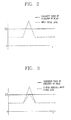
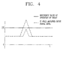
- FIGS. 2 and 4 show embodiments in which different amplification factors are applied to optical signals for sensing an arc according to a length of an optical fiber cable, in particular, an optical cable for a point sensor.
- FIG. 2 is a graph showing a signal waveform when an optical signal for sensing an arc passes through an optical fiber cable having Xm and having a quantity of light of, for example, 25000 lux, according to an embodiment of the present invention.
- an amplification factor in this case is X.
- FIG. 3 is a graph showing a signal waveform when an optical signal for sensing an arc passes through an optical fiber cable having 2Xm and having a quantity of light of, for example, 25000 lux, according to an embodiment of the present invention.
- FIG. 3 illustrates a waveform of a signal having an amplification factor amplified by approximately X'-fold with respect an input signal.
- FIG. 4 is a graph showing a signal waveform when an optical signal for sensing an arc passes through an optical fiber cable having 3X and having a quantity of light of, for example, 25000 lux, according to an embodiment of the present invention.
- FIG. 4 illustrates a waveform of a signal having an amplification factor amplified by approximately X"-fold with respect an input signal.
- the signal has a magnitude of a signal level not exceeding a predetermined reference value as a reference for determining an occurrence of an arc, resultantly degrading a function of the digital protection relay.
- an amplification factor of an input signal is increased proportionally (i.e., in proportion to the length of the optical fiber cable) in order to compensate for loss of the quantity of light with respect to the input signal.
- an occurrence of an arc can be more accurately detected, to thus optimally protect power facilities and humans from an arc accident.
- an optical signal for sensing an arc is applied through a point channel and/or a loop channel.
- the point channel and the loop channel are independently configured.
- the applied optical signal is converted into an electrical signal through a predetermined signal conversion unit.
- the microcomputer determines an amplification factor with respect to the converted optical signal and output it as a control signal to the amplifying unit.
- the amplification factor with respect to the optical signal may vary according to a length of the optical fiber cable through which the optical signal is transmitted.
- an attenuation rate of a magnitude of the converted electrical signal is further increased, and thus, as the length of the optical fiber cable is increased, a signal amplification factor should be increased.
- a signal amplification factor is X.
- the amplification factor is increased to 2X, and if a length of the optical fiber is 3m over the same quantity of light, the amplification factor is increased to 3X, thereby compensating for a signal level attenuation rate increased due to the increase in the length of the optical fiber cable.
- an optical signal amplified in proportion to a length of an optical fiber cable and a predetermined reference value are compared, and when a magnitude of the amplified optical signal is greater according to the comparison results, it is determined that an arc has occurred, and a trip signal for interrupting an input current is output.
- an amplification factor compensating for a loss of a quantity of light is applied according to a length of an optical fiber cable for a point sensor, whereby an occurrence of an arc can be more accurately detected, and thus, power facilities and human causalities can be optimally protected from an arc accident.
- a different amplification factor is applied such that a loss of a quantity of light with respect to an input signal is compensated for according to a length of an optical fiber cable for a point sensor, whereby an occurrence of an arc can be more accurately detected, and thus, power facilities and human causalities can be optimally protected from an arc accident.
Landscapes
- Physics & Mathematics (AREA)
- Electromagnetism (AREA)
- Engineering & Computer Science (AREA)
- Computer Networks & Wireless Communication (AREA)
- Signal Processing (AREA)
- General Physics & Mathematics (AREA)
- Emergency Protection Circuit Devices (AREA)
- Lasers (AREA)
Abstract
Description
- The present disclosure relates to a digital protection relay and, more particularly, to a digital protection relay implemented to selectively apply an amplification factor (or an amplification rate) according to an optical signal for detecting an occurrence of an arc.
- Various power facilities (or power utilities) are intricately associated in an electric power system, so when a portion of a electric power system is broken down (or fails), a failed portion is required to be quickly separated from the system, and here, a digital protection relay serves to do it.
- In general, an occurrence of an accident due to an arc resulting from a short-circuit or degraded insulation within a distribution board may affect power instruments and power devices within the distribution board due to high temperature and high pressure, and cause power failure which may require a long period of time for its recovery. Namely, an accident due to an electrical arc causes various problems.
- An arc protection function configuration may be divided into a method for receiving light through a point sensor and a method for receiving light through a loop sensor. Here, a point sensor may be used for the purpose of monitoring a particular point of a distribution board, which receives light at an end portion of an optical cable. In the case of a loop sensor, an optical cable is installed extendedly within a distribution board, and a loop sensor converts an optical signal input through the side of the optical cable into an electrical signal, whereby the loop sensor receives a signal signals through the entirety of the optical fiber.
- The loop sensor has characteristics that an attenuation rate of optical fiber is low and a light detection range is as low as ±10 degrees. Meanwhile, in the case of an optical cable used for a point sensor, since a light is received at an end of the optical cable as mentioned above, a light detection range thereof should be ±90 degrees or greater, having a disadvantage in that an attenuation rate of optical fiber that satisfies such characteristics is increased.
- Thus, as a length of an optical cable for a point sensor is increased, an attenuation rate thereof is also increased, resulting in an occurrence of malfunction of the arc protection relay.
- Therefore, an aspect of the detailed description is to provide a digital protection relay in which a different attenuation rate is applied according to a length of an optical cable for a point sensor when the optical cable is used.
- To achieve these and other advantages and in accordance with the purpose of this specification, as embodied and broadly described herein, a digital protection relay includes: an optical fiber cable, for a point sensor, configured to transmit an optical signal for sensing an arc; a signal conversion unit configured to convert the optical signal into an electrical signal, and output the converted electrical signal; an amplifying unit configured to selectively apply an amplification factor to the electrical signal on the basis of a control signal, and output the same; and a microcomputer configured to output the control signal for determining the amplification factor according to a length of the optical fiber cable, and determine whether to drive the digital protection relay according to results obtained by comparing the amplified electrical signal with a predetermined reference value.
- In an embodiment, the amplifying unit may include a plurality of operational amplifiers and selectively drive the operational amplifiers to have an amplification factor proportional to a length of the optical fiber cable according to the control signal received from the microcomputer.
- In an embodiment, the microcomputer may include an amplification factor determining unit configured to compare the amplification factor proportional to a length of the optical fiber cable with an amplification factor with respect to a predetermined reference length to determine the amplification factor; and a comparing and determining unit configured to compare a magnitude of the electrical signal output from the amplifying unit with a predetermined reference value to determine whether an arc has occurred.
- In an embodiment, the digital protection relay may further include: an output unit configured to display value '1' when the magnitude of the electrical signal is equal to or greater than the reference value according to the comparison results from the comparing and determining unit, and display value '0' when the magnitude of the electrical signal is smaller than the reference value.
- In an embodiment, when a value displayed on the output unit is 1, the microcomputer may determine that an arc has occurred, and output a trip signal.
- To achieve these and other advantages and in accordance with the purpose of this specification, as embodied and broadly described herein, a digital protection relay includes: an optical fiber cable, for a point sensor, configured to transmit an optical signal for sensing an arc; a signal conversion unit configured to convert the optical signal into an electrical signal, and output the converted electrical signal; an amplifying unit including a plurality of operational amplifiers and configured to selectively drive the operational amplifiers to output the electrical signal having a corresponding amplification factor; and a microcomputer configured to sense a length of the optical fiber cable on the basis of a transfer rate of the optical signal, determine an amplification factor in proportion to the length of the optical fiber cable, and output the control signal.
- In an embodiment, the amplifying unit may include: one or more switching units configured to selectively drive the plurality of operational amplifiers.
- In an embodiment, the microcomputer may compare the amplified electrical signal with a predetermined reference value, and determine whether to output a trip signal according to the comparison results.
- In an embodiment, when the amplified electrical signal has value equal to or greater than a reference value, the microcomputer may generate a trip signal.
- According to embodiments of the present invention, since an amplification factor is differently applied such that loss of a quantity of light with respect to an input signal is compensated for according to a length of an optical fiber cable for a point sensor. Thus, an occurrence of an arc can be more accurately detected, whereby power facilities and humans can be optimally protected from an arc accident.
- Further scope of applicability of the present application will become more apparent from the detailed description given hereinafter. However, it should be understood that the detailed description and specific examples, while indicating preferred embodiments of the invention, are given by way of illustration only, since various changes and modifications within the spirit and scope of the invention will become apparent to those skilled in the art from the detailed description.
- The accompanying drawings, which are included to provide a further understanding of the invention and are incorporated in and constitute a part of this specification, illustrate exemplary embodiments and together with the description serve to explain the principles of the invention.
- In the drawings:
-
FIG. 1 a block diagram illustrating a configuration of a digital protection relay according to an embodiment of the present invention; -
FIG. 2 is a view illustrating a signal waveform when an optical signal for sensing an arc passes through an optical fiber cable having an X length; -
FIG. 3 is a view illustrating a signal waveform when an optical signal for sensing an arc passes through an optical fiber cable having a 2X length; and -
FIG. 4 is a view illustrating a signal waveform when an optical signal for sensing an arc passes through an optical fiber cable having a 3X length. - Description will now be given in detail of the exemplary embodiments, with reference to the accompanying drawings. For the sake of brief description with reference to the drawings, the same or equivalent components will be provided with the same reference numbers, and description thereof will not be repeated.
- Hereinafter, a digital protection relay according to an embodiment of the present invention will be described in detail with reference to the accompanying drawings. In describing the present invention, if a detailed explanation for a related known function or construction is considered to unnecessarily divert the gist of the present invention, such explanation will be omitted but would be understood by those skilled in the art. Also, similar reference numerals are used for the similar parts throughout the specification.
- First, referring to
FIG. 1 , a digital protection relay according to an embodiment of the present invention may include an opticalsignal input unit 10, asignal conversion unit 20, anamplifying unit 30, amicrocomputer 40, and anoutput unit 50. However, this configuration may be modified as necessary. - The optical
signal input unit 10 may receive an optical signal through, for example, a point channel and/or a loop channel. - The
signal conversion unit 20 may convert the optical signal into an electrical signal, and output the converted electrical signal. Also, thesignal conversion unit 20 may convert an analog signal into a digital signal and output the converted digital signal to themicrocomputer 40. - The amplifying
unit 30 may selectively apply an amplification factor to the electrical signal on the basis of a control signal. In detail, the amplifyingunit 30 differently applies an amplification factor to the converted optical signal according to a control signal output from themicrocomputer 40. For example, the amplifyingunit 30 may increase an amplification factor with respect to an optical signal having a high attenuation rate, and decrease an amplification factor with respect to an optical signal having a low attenuation rate. In particular, in the case of an optical fiber cable for a point sensor, as a length thereof is increased, an attenuation rate thereof is also increased. Thus, themicrocomputer 40 determines an amplification factor with respect to an optical signal in consideration of a length of an optical fiber cable and a quantity of light, and transfers the determined amplification factor in the form of a control signal to the amplifyingunit 30. - The amplifying
unit 30 may include a plurality of operational amplifiers selectively driven on the basis of a control signal received from themicrocomputer 40. Thus, the amplifyingunit 30 may have an amplification factor proportional to a length of the optical fiber cable on the basis of the plurality of selectively driven operational amplifiers. The operational amplifiers may be provided by the amount required for amplifying the amplification factor one time, twice, trebly, and quadruply. - Also, the amplifying
unit 30 may include one or more switching units (not shown) for selectively driving the plurality of operational amplifiers according to the amplification factor. The switching unit may be configured as a mechanical switching unit or a relay, for example. For example, in a case in which a smaller amount of operational amplifiers are used, some operational amplifiers may be commonly used, and to this end, a switching unit (not shown) may be connected to the commonly used operational amplifiers. In this case, the switching unit may be differentially turned on or off according to a control signal from themicrocomputer 40. - Based on a length of an optical fiber cable, the
microcomputer 40 may determine an amplification factor in proportion to the length of the optical fiber cable, and output the determined amplification factor as the control signal. Here, the optical fiber cable is a cable for transmitting an optical signal for sensing an arc, and here, the optical fiber cable refers to an optical fiber cable for a point sensor. Also, themicrocomputer 40 may compare the amplified electrical signal with a predetermined reference value, and determine whether to drive the digital protection relay according to the comparison results. - Also, as illustrated in
FIG. 1 , themicrocomputer 40 may include an amplificationfactor determining unit 42 and a comparing and determiningunit 45. In detail, the amplificationfactor determining unit 42 may compare an amplification factor proportional to a length of the optical fiber cable with an amplification factor with respect to a reference length. Also, the comparing and determiningunit 45 may determine whether or not an arc has occurred by comparing a magnitude of an electrical signal output from the amplifyingunit 30 with a predetermined reference value. Here, the reference value refers to a minimum reference value for determining an occurrence of an arc. - In addition, the
microcomputer 40 may compare the amplified optical signal from the amplifyingunit 30 with a predetermined reference value to determine whether or not an arc has occurred according to the comparison results, and determine whether to output a trip signal. - When the magnitude of the electrical signal is equal to or greater than the reference value according to the comparison results of the comparing and determining
unit 45 of themicrocomputer 40, theoutput unit 50displays value 1. Also, when the magnitude of the electrical signal is smaller than the reference value, theoutput unit 50displays value 0. To this end, theoutput unit 50 may include a display screen configured as a liquid crystal display (LCD), a light emitting diode (LED) display, or the like. - In an embodiment, when the amplified electrical signal is equal to or greater than the reference value according to the comparison results, the
microcomputer 40 may generate a trip signal. The trip signal may interrupt an input current by using a signal of a protection relay of a circuit breaker, thus protecting power facilities from an arc. - In an embodiment, when a value displayed on the
output unit 50 is 1, themicrocomputer 40 may determine that an arc has occurred, and output a trip signal. Meanwhile, when a value displayed on theoutput unit 50 is 0, themicrocomputer 40 determines that an arc has not occurred, so it does not drive the digital protection relay. - In an embodiment, the amplifying
unit 30 includes a plurality of operational amplifiers. The amplifyingunit 30 may selectively drive the operational amplifiers according to a control signal received from themicrocomputer 40, apply a corresponding amplification factor to an input signal (i.e., apply a different amplification factor to each input signal), and output the same. - Here, the
microcomputer 40 may calculate a transfer rate of the optical signal that passes though the optical fiber cable through a predetermined calculation process to roughly detect a length of the optical fiber cable. In this case, however, a transfer rate of the optical signal may vary according to a type of a used cable, a transmission mode, or a signal modulation scheme, so it is based upon the premise that these are under the same conditions or the values are previously known. In this case, themicrocomputer 40 may determine an amplification factor with respect to the input signal such that it is proportional to the sensed length of the optical fiber cable, and output a corresponding control signal to the amplifyingunit 40. - In this connection,
FIGS. 2 and4 show embodiments in which different amplification factors are applied to optical signals for sensing an arc according to a length of an optical fiber cable, in particular, an optical cable for a point sensor. -
FIG. 2 is a graph showing a signal waveform when an optical signal for sensing an arc passes through an optical fiber cable having Xm and having a quantity of light of, for example, 25000 lux, according to an embodiment of the present invention. Here, it is assumed that an amplification factor in this case is X. Meanwhile,FIG. 3 is a graph showing a signal waveform when an optical signal for sensing an arc passes through an optical fiber cable having 2Xm and having a quantity of light of, for example, 25000 lux, according to an embodiment of the present invention. Here,FIG. 3 illustrates a waveform of a signal having an amplification factor amplified by approximately X'-fold with respect an input signal. Also,FIG. 4 is a graph showing a signal waveform when an optical signal for sensing an arc passes through an optical fiber cable having 3X and having a quantity of light of, for example, 25000 lux, according to an embodiment of the present invention. Here,FIG. 4 illustrates a waveform of a signal having an amplification factor amplified by approximately X"-fold with respect an input signal. - As illustrated in
FIGS. 3 and4 , as the length of the optical fiber cable, in particular, the optical cable for a point sensor, is increased, loss of the quantity of light is proportionally increased to attenuate a magnitude of the signal. Thus, the signal has a magnitude of a signal level not exceeding a predetermined reference value as a reference for determining an occurrence of an arc, resultantly degrading a function of the digital protection relay. Thus, in accordance with an embodiment of the present invention, as a length of the optical fiber cable, in particular, the optical cable for a point sensor, sensed by themicrocomputer 40 or any other independent device is increased, an amplification factor of an input signal is increased proportionally (i.e., in proportion to the length of the optical fiber cable) in order to compensate for loss of the quantity of light with respect to the input signal. In addition, in this manner, an occurrence of an arc can be more accurately detected, to thus optimally protect power facilities and humans from an arc accident. - Hereinafter, an operation of the digital protection relay according to an embodiment of the present invention will be described. First, an optical signal for sensing an arc is applied through a point channel and/or a loop channel. In general, the point channel and the loop channel are independently configured. The applied optical signal is converted into an electrical signal through a predetermined signal conversion unit. Then, the microcomputer determines an amplification factor with respect to the converted optical signal and output it as a control signal to the amplifying unit. In this case, the amplification factor with respect to the optical signal may vary according to a length of the optical fiber cable through which the optical signal is transmitted. Namely, as the length of the optical fiber cable is increased, an attenuation rate of a magnitude of the converted electrical signal is further increased, and thus, as the length of the optical fiber cable is increased, a signal amplification factor should be increased. For example, it is assumed that when a quantity of light of an applied optical signal is 2500 lux and a length of an optical fiber is approximately 10m, an amplification factor is X. Then, if a length of the optical fiber is 20m over the same quantity of light, the amplification factor is increased to 2X, and if a length of the optical fiber is 3m over the same quantity of light, the amplification factor is increased to 3X, thereby compensating for a signal level attenuation rate increased due to the increase in the length of the optical fiber cable. In this manner, an optical signal amplified in proportion to a length of an optical fiber cable and a predetermined reference value are compared, and when a magnitude of the amplified optical signal is greater according to the comparison results, it is determined that an arc has occurred, and a trip signal for interrupting an input current is output. In this case, it may be implemented such that when a duration in which a magnitude of the amplified optical signal is maintained to be greater than a predetermined reference value exceeds a predetermined duration, it is determined that an arc has occurred and a trip signal is output.
- As described above, in the case of the digital protection relay according to an embodiment of the present invention, an amplification factor compensating for a loss of a quantity of light is applied according to a length of an optical fiber cable for a point sensor, whereby an occurrence of an arc can be more accurately detected, and thus, power facilities and human causalities can be optimally protected from an arc accident.
- In addition, according to an embodiment of the present invention, a different amplification factor is applied such that a loss of a quantity of light with respect to an input signal is compensated for according to a length of an optical fiber cable for a point sensor, whereby an occurrence of an arc can be more accurately detected, and thus, power facilities and human causalities can be optimally protected from an arc accident.
- The foregoing embodiments and advantages are merely exemplary and are not to be considered as limiting the present disclosure. The present teachings can be readily applied to other types of apparatuses. This description is intended to be illustrative, and not to limit the scope of the claims. Many alternatives, modifications, and variations will be apparent to those skilled in the art. The features, structures, methods, and other characteristics of the exemplary embodiments described herein may be combined in various ways to obtain additional and/or alternative exemplary embodiments.
- As the present features may be embodied in several forms without departing from the characteristics thereof, it should also be understood that the above-described embodiments are not limited by any of the details of the foregoing description, unless otherwise specified, but rather should be considered broadly within its scope as defined in the appended claims, and therefore all changes and modifications that fall within the metes and bounds of the claims, or equivalents of such metes and bounds are therefore intended to be embraced by the appended claims.
Claims (4)
- A digital protection relay comprising:an optical fiber cable, for a point sensor, configured to transmit an optical signal for sensing an arc;a signal conversion unit 20 configured to convert the optical signal into an electrical signal, and output the converted electrical signal;an amplifying unit 30 configured to selectively apply an amplification factor to the electrical signal on the basis of a control signal, and output the same; anda microcomputer 40 configured to output the control signal for determining the amplification factor according to a length of the optical fiber cable, and determine whether to drive the digital protection relay according to results obtained by comparing the amplified electrical signal with a predetermined reference value.
- The digital protection relay of claim 1, wherein the amplifying unit 30 includes a plurality of operational amplifiers and selectively drives the operational amplifiers to have an amplification factor proportional to a length of the optical fiber cable according to the control signal received from the microcomputer 40.
- The digital protection relay of any of claims 1 to 2, wherein the microcomputer 40 comprises:an amplification factor determining unit 42 configured to compare the amplification factor proportional to a length of the optical fiber cable with an amplification factor with respect to a predetermined reference length to determine the amplification factor; anda comparing and determining unit 45 configured to compare a magnitude of the electrical signal output from the amplifying unit 30 with a predetermined reference value to determine whether an arc has occurred.
- The digital protection relay of claim 3, further comprising:an output unit 50 configured to display value '1' when the magnitude of the electrical signal is equal to or greater than the reference value according to the comparison results from the comparing and determining unit 45, and display value '0' when the magnitude of the electrical signal is smaller than the reference value,wherein when a value displayed on the output unit 50 is 1, the microcomputer 40 may determined that an arc has occurred, and output a trip signal.
Applications Claiming Priority (1)
| Application Number | Priority Date | Filing Date | Title |
|---|---|---|---|
| KR1020120042829A KR101266834B1 (en) | 2012-04-24 | 2012-04-24 | Digital protection relay |
Publications (1)
| Publication Number | Publication Date |
|---|---|
| EP2658060A1 true EP2658060A1 (en) | 2013-10-30 |
Family
ID=48128207
Family Applications (1)
| Application Number | Title | Priority Date | Filing Date |
|---|---|---|---|
| EP13164462.7A Withdrawn EP2658060A1 (en) | 2012-04-24 | 2013-04-19 | Digital protection relay |
Country Status (4)
| Country | Link |
|---|---|
| US (1) | US20130279902A1 (en) |
| EP (1) | EP2658060A1 (en) |
| KR (1) | KR101266834B1 (en) |
| CN (1) | CN103378586B (en) |
Families Citing this family (1)
| Publication number | Priority date | Publication date | Assignee | Title |
|---|---|---|---|---|
| KR102469366B1 (en) | 2020-08-04 | 2022-11-23 | 한국전력공사 | System and Method for testing protection relay |
Citations (2)
| Publication number | Priority date | Publication date | Assignee | Title |
|---|---|---|---|---|
| WO1980001442A1 (en) * | 1978-12-27 | 1980-07-10 | Bbc Brown Boveri & Cie | Supervision device with an optical detector for electrical arcs in a circuit-breaker |
| WO2002021657A1 (en) * | 2000-09-01 | 2002-03-14 | The Johns Hopkins University | Fiber optic light sensor system |
Family Cites Families (12)
| Publication number | Priority date | Publication date | Assignee | Title |
|---|---|---|---|---|
| US4814774A (en) * | 1986-09-05 | 1989-03-21 | Herczfeld Peter R | Optically controlled phased array system and method |
| US6337906B1 (en) * | 1997-05-23 | 2002-01-08 | Microlog Corporation | Apparatus and method for coupling an automated attendant to a telecommunications system |
| WO1999059025A1 (en) * | 1998-05-08 | 1999-11-18 | University Of Michigan | Soliton pulse transmission over waveguide fiber lengths |
| US6172490B1 (en) * | 1999-12-08 | 2001-01-09 | Alcatel Networks Corporation | Precise rail tracking method for powering dual voltage integrated circuits |
| JP2002050961A (en) * | 2000-08-02 | 2002-02-15 | Mitsubishi Electric Corp | Phase lock loop circuit |
| US20040223064A1 (en) * | 2002-10-24 | 2004-11-11 | Canon Kabushiki Kaisha | Image pickup element, image pickup device, and differential amplifying circuit |
| US7186033B2 (en) * | 2005-02-23 | 2007-03-06 | Schlumberger Technology Corporation | Fiber optic booster connector |
| US8582266B2 (en) * | 2006-02-17 | 2013-11-12 | Broadcom Corporation | Current-monitoring apparatus |
| WO2010033845A1 (en) * | 2008-09-19 | 2010-03-25 | Schweitzer Engineering Laboratories, Inc. | Protective device with metering and oscillography |
| JP4766095B2 (en) * | 2008-10-09 | 2011-09-07 | ソニー株式会社 | Charger |
| US8223466B2 (en) * | 2009-06-30 | 2012-07-17 | General Electric Company | Arc flash detection |
| US8040517B1 (en) * | 2010-04-30 | 2011-10-18 | General Electric Company | Arc flash detection system and method |
-
2012
- 2012-04-24 KR KR1020120042829A patent/KR101266834B1/en active Active
-
2013
- 2013-04-19 EP EP13164462.7A patent/EP2658060A1/en not_active Withdrawn
- 2013-04-23 US US13/868,904 patent/US20130279902A1/en not_active Abandoned
- 2013-04-24 CN CN201310146220.0A patent/CN103378586B/en not_active Expired - Fee Related
Patent Citations (2)
| Publication number | Priority date | Publication date | Assignee | Title |
|---|---|---|---|---|
| WO1980001442A1 (en) * | 1978-12-27 | 1980-07-10 | Bbc Brown Boveri & Cie | Supervision device with an optical detector for electrical arcs in a circuit-breaker |
| WO2002021657A1 (en) * | 2000-09-01 | 2002-03-14 | The Johns Hopkins University | Fiber optic light sensor system |
Also Published As
| Publication number | Publication date |
|---|---|
| CN103378586A (en) | 2013-10-30 |
| CN103378586B (en) | 2016-08-03 |
| US20130279902A1 (en) | 2013-10-24 |
| KR101266834B1 (en) | 2013-05-27 |
Similar Documents
| Publication | Publication Date | Title |
|---|---|---|
| EP2905662B1 (en) | Redundant computation processing system | |
| US9794273B2 (en) | Monitoring control system | |
| KR101478507B1 (en) | High voltage distributing board, low voltage distributing board, distribuging board, motor contorl board monitoring intact overheat for connector | |
| WO2009120324A3 (en) | Arc fault root-cause finder system and method | |
| CN101358888A (en) | Pressure and temperature sensor | |
| KR100900273B1 (en) | Electricity meter with arc detection | |
| AU2012355651B2 (en) | High speed signaling of power system conditions | |
| US20130279902A1 (en) | Digital protection relay | |
| JP5119026B2 (en) | Optical CT application equipment | |
| WO2002021657A1 (en) | Fiber optic light sensor system | |
| EP2110917A2 (en) | Method of setting a ground fault trip function for a trip unit and a trip unit having a defined trip function for ground fault protection | |
| KR101481384B1 (en) | Method of monitoring deterioration by non-contact detectiong of temperature of high voltage distributing board, low voltage distributing board, distributing board, motor control board sunlight connector band | |
| CN110648487A (en) | Smog monitoring circuit and display screen | |
| KR101005089B1 (en) | Digital Protection Relay Device for Switchgear | |
| KR20190108438A (en) | Management system for circuit breakers in distribution panel | |
| KR101442178B1 (en) | A Distributing Board System having Malfunction Diagnosing Function | |
| JP4543007B2 (en) | Current differential protection system | |
| KR20190022123A (en) | A ring main unit system for preventing electrical accident using temparature and pressure | |
| KR20100138244A (en) | Circuit Breaker with Data Processing and Wireless Communication Function | |
| KR20120034857A (en) | Protected circuit for serge and drive mechanism system | |
| KR102911113B1 (en) | Live wire signal display apparatus having live wire distributing function | |
| KR200350414Y1 (en) | Monitoring system for distribution board using ESS | |
| KR101668434B1 (en) | Monitoring system for electric power apparatus | |
| KR102874480B1 (en) | Power distribution unit with multiple protection functions | |
| WO2012111936A2 (en) | Leaking current shut-off device for preventing malfunction due to a surge |
Legal Events
| Date | Code | Title | Description |
|---|---|---|---|
| PUAI | Public reference made under article 153(3) epc to a published international application that has entered the european phase |
Free format text: ORIGINAL CODE: 0009012 |
|
| AK | Designated contracting states |
Kind code of ref document: A1 Designated state(s): AL AT BE BG CH CY CZ DE DK EE ES FI FR GB GR HR HU IE IS IT LI LT LU LV MC MK MT NL NO PL PT RO RS SE SI SK SM TR |
|
| AX | Request for extension of the european patent |
Extension state: BA ME |
|
| 17P | Request for examination filed |
Effective date: 20140331 |
|
| RBV | Designated contracting states (corrected) |
Designated state(s): AL AT BE BG CH CY CZ DE DK EE ES FI FR GB GR HR HU IE IS IT LI LT LU LV MC MK MT NL NO PL PT RO RS SE SI SK SM TR |
|
| STAA | Information on the status of an ep patent application or granted ep patent |
Free format text: STATUS: THE APPLICATION HAS BEEN WITHDRAWN |
|
| 18W | Application withdrawn |
Effective date: 20161125 |