EP2657888A1 - Apparatus for reading magnetic recording medium - Google Patents
Apparatus for reading magnetic recording medium Download PDFInfo
- Publication number
- EP2657888A1 EP2657888A1 EP10860934.8A EP10860934A EP2657888A1 EP 2657888 A1 EP2657888 A1 EP 2657888A1 EP 10860934 A EP10860934 A EP 10860934A EP 2657888 A1 EP2657888 A1 EP 2657888A1
- Authority
- EP
- European Patent Office
- Prior art keywords
- magnetic
- card
- magnetic field
- frequency
- interfering
- Prior art date
- Legal status (The legal status is an assumption and is not a legal conclusion. Google has not performed a legal analysis and makes no representation as to the accuracy of the status listed.)
- Granted
Links
Images





Classifications
-
- G—PHYSICS
- G07—CHECKING-DEVICES
- G07F—COIN-FREED OR LIKE APPARATUS
- G07F7/00—Mechanisms actuated by objects other than coins to free or to actuate vending, hiring, coin or paper currency dispensing or refunding apparatus
- G07F7/08—Mechanisms actuated by objects other than coins to free or to actuate vending, hiring, coin or paper currency dispensing or refunding apparatus by coded identity card or credit card or other personal identification means
- G07F7/0873—Details of the card reader
-
- G—PHYSICS
- G06—COMPUTING OR CALCULATING; COUNTING
- G06K—GRAPHICAL DATA READING; PRESENTATION OF DATA; RECORD CARRIERS; HANDLING RECORD CARRIERS
- G06K7/00—Methods or arrangements for sensing record carriers, e.g. for reading patterns
- G06K7/08—Methods or arrangements for sensing record carriers, e.g. for reading patterns by means detecting the change of an electrostatic or magnetic field, e.g. by detecting change of capacitance between electrodes
-
- G—PHYSICS
- G06—COMPUTING OR CALCULATING; COUNTING
- G06K—GRAPHICAL DATA READING; PRESENTATION OF DATA; RECORD CARRIERS; HANDLING RECORD CARRIERS
- G06K17/00—Methods or arrangements for effecting co-operative working between equipments covered by two or more of main groups G06K1/00 - G06K15/00, e.g. automatic card files incorporating conveying and reading operations
-
- G—PHYSICS
- G06—COMPUTING OR CALCULATING; COUNTING
- G06K—GRAPHICAL DATA READING; PRESENTATION OF DATA; RECORD CARRIERS; HANDLING RECORD CARRIERS
- G06K7/00—Methods or arrangements for sensing record carriers, e.g. for reading patterns
-
- G—PHYSICS
- G06—COMPUTING OR CALCULATING; COUNTING
- G06K—GRAPHICAL DATA READING; PRESENTATION OF DATA; RECORD CARRIERS; HANDLING RECORD CARRIERS
- G06K7/00—Methods or arrangements for sensing record carriers, e.g. for reading patterns
- G06K7/08—Methods or arrangements for sensing record carriers, e.g. for reading patterns by means detecting the change of an electrostatic or magnetic field, e.g. by detecting change of capacitance between electrodes
- G06K7/082—Methods or arrangements for sensing record carriers, e.g. for reading patterns by means detecting the change of an electrostatic or magnetic field, e.g. by detecting change of capacitance between electrodes using inductive or magnetic sensors
-
- G—PHYSICS
- G07—CHECKING-DEVICES
- G07F—COIN-FREED OR LIKE APPARATUS
- G07F19/00—Complete banking systems; Coded card-freed arrangements adapted for dispensing or receiving monies or the like and posting such transactions to existing accounts, e.g. automatic teller machines
- G07F19/20—Automatic teller machines [ATMs]
- G07F19/205—Housing aspects of ATMs
- G07F19/2055—Anti-skimming aspects at ATMs
Definitions
- control unit may determine whether or not the interfering magnetic field generated by the magnetic field generating unit is normally received by the magnetic head based on a level of a signal output from the magnetic stripe detecting unit in a period other than the pause period.
- the control unit 2 includes a magnetic field control unit 9 for controlling the magnetic field generating unit 8 and a card carriage control unit 12 for controlling the card carrying unit 4.
- the magnetic stripe detecting unit 10 and the magnetic field generating unit 8 are disposed in a card insertion port unit 24.
- the magnetic stripe detecting unit 10 includes a magnetic head 34 ( Fig. 2a ) which will be described later.
- the magnetic field generating unit 8 includes a loop antenna 35 ( Fig. 2b ) which will be described later.
- the magnetic head 29 is provided on the lower side of the carrier path P between the carrier rollers 26 and the carrier rollers 27.
- the magnetic head 29 reads data recorded in the magnetic stripe 21a of the card 21 in the process of carriage of the inserted card 21 in the carrier path P.
- the magnetic head 34 is a magnetic head for detecting the existence of data recorded in a magnetic stripe whereas the magnetic head 29 is a magnetic head for reproducing data itself recorded in the magnetic stripe.
- the interval between the magnetic head 29 and the sensor 33 is slightly longer than the length in the carriage direction of the card 21. Therefore, when the card 21 reaches the storage part, that is, when the front end of the card 21 reaches the position of the sensor 33, the magnetic head 29 completes reading of the data recorded in the card 21.
- the magnetic head 34 Since the interfering magnetic field acts on the magnetic head 34 for detecting a magnetic stripe while the interfering magnetic field is generated by the loop antenna 35, the magnetic head 34 cannot read magnetic data of the card 21. Therefore, even if the skimming of the second type of coupling a lead wire to the output terminal of the magnetic stripe detecting unit 10 and reading magnetic data of the card 21 by an illegal reader via the lead wire is performed, the magnetic data of the card 21 cannot be taken in the interfering magnetic field generation periods (the periods other than X).
- the third embodiment by making the interfering magnetic field acted on the magnetic head 34 and reading the data of the card 21 by the magnetic head 34 in a period of a specific frequency while changing the frequency of the interfering magnetic field, a measure against skimming similar to that in the first embodiment can be performed. Since the interfering magnetic field always acts on the magnetic head 34, a measure against an illegal act can be performed more reliably.
- the control unit 2 determines whether or not the sensor 33 disposed next to the carrier roller 28 detects the end (the right end in Fig. 2a ) of the card 21 (step S27).
- the control unit 2 repeatedly executes the step S27. Specifically, the control unit 2 rotates the carrier rollers 25 to 28 in the forward direction and continues carriage of the card 21 until the card end is detected.
- the control unit 2 determines that the carried card 21 has reached the rear end of the carrier path P and stops the rotation of the carrier rollers 25 to 28 by the card carriage control unit 12 to cease carrying the card 21 (step S28).
Landscapes
- Engineering & Computer Science (AREA)
- Physics & Mathematics (AREA)
- General Physics & Mathematics (AREA)
- Theoretical Computer Science (AREA)
- Artificial Intelligence (AREA)
- Computer Vision & Pattern Recognition (AREA)
- Business, Economics & Management (AREA)
- Accounting & Taxation (AREA)
- Finance (AREA)
- Recording Or Reproducing By Magnetic Means (AREA)
- Control Of Vending Devices And Auxiliary Devices For Vending Devices (AREA)
Abstract


Description
- The present invention relates to a device for reading data recorded in a magnetic recording medium and, more particularly, to a magnetic recording medium reading device having the function of preventing illegal data acquisition.
- In a transaction processing device such as an ATM (Automated Teller Machine) or a CD (Cash Dispenser), a card reader for reading a magnetic card is installed. In such a transaction processing device, recently, a crime called skimmingof illegally obtaining data recorded in a magnetic stripe of a card when the magnetic card is inserted in a card reader occurs.
- There are roughly two types in skimming. One of them (hereinbelow, called "first type") is that an illegal reader having a magnetic head is installed so as to cover a card insertion port of a card reader of an ATM or a CD, and data of a magnetic card inserted in the card reader is illegally obtained by the magnetic head of the illegal reader. The other type (hereinbelow, called "second type") is that an illegal reader is connected to a magnetic stripe detector including a magnetic head for detecting a magnetic stripe installed near a card insertion port via a lead wire, and a signal output from the magnetic stripe detector (data read by the magnetic head) is illegally obtained via the lead wire.
- Various measures against such skimming have been proposed. For example, the following
Patent Literature 1 describes a card reader having an interfering magnetic field generator provided near a card insertion port. In the card reader, an interfering magnetic field is generated in an outside region of the card insertion port by the interfering magnetic field generator. Consequently, even if an illegal reader is attached to the outside of a card insertion port, data read by the illegal reader is data different from original data recorded in a card under the influence of the interfering magnetic field. In such a manner, data of a card can be prevented from being illegally taken. - In addition, the following
Patent Literature 2 describes a card reader in which a loop antenna for generating an interfering magnetic field is disposed around a card insertion port. The antenna face of the loop antenna is parallel to the front face of the card insertion port. Also in the card reader, an interfering magnetic field is generated in an outside region of the card insertion port. Therefore, even if an illegal reader is attached to the outside of the card insertion port, data of a card can be prevented from being illegally taken. - Further, the following
Patent Literature 3 describes a card reader having a pre-head for detecting a magnetic stripe of a card, which is disposed near a card insertion port, and outputting a signal different from that of magnetic information recorded in the magnetic stripe therefrom. In the card reader, even if an illegal reader is attached to the pre-head via a lead wire, a signal output from the pre-head is a signal different from that of information recorded in a card, so that data of a card can be prevented from being illegally taken. -
- Patent Literature 1: Japanese Laid-Open Patent Publication No.
2001-67524 - Patent Literature 2: Japanese Patent No.
4425674 - Patent Literature 3: Japanese Laid-Open Patent Publication No.
2010-205187 - The card reader described in
Patent Literature 1 is effective against skimming of the first type of attaching an illegal reader to the outside of a card insertion port since an interfering magnetic field is generated in the outside region of the card insertion port. In the card reader, however, in the case where the skimming of the second type of attaching an illegal reader to a magnetic stripe detector via a lead wire is performed, there is the possibility that data is illegally taken. - The card reader described in
Patent Literature 2 is also effective against the skimming of the first type since an interfering magnetic field is generated in the outside region of a card insertion port. However, the card reader is not provided with a magnetic head for detecting a magnetic stripe, and a measure against the skimming of the second type is not considered. - The card reader of
Patent Literature 3 is effective against the skimming of the second type since a signal which is output from the pre-head is a signal different from that of information recorded in a card. In the card reader, however, signal converting means for converting a signal read by the head of the pre-head to a signal different from the read signal is necessary, and the configuration is therefore complicated. Moreover, since a measure against the skimming of the first type is not taken, data may be illegally taken by an illegal reader attached to the outside of a card insertion port. - An object of the present invention is therefore to provide a magnetic recording medium reading device capable of effectively preventing illegal data acquisition, particularly, against skimming of the second type. Another object of the present invention is to provide a magnetic recording medium reading device that is also effective against skimming of the first type.
- A magnetic recording medium reading device according to the present invention includes: an insertion port in which a magnetic recording medium is to be inserted; a magnetic stripe detecting unit including a magnetic head that detects a magnetic stripe of the magnetic recording medium; a magnetic field generating unit that generates an interfering magnetic field to disturb reading of data recorded in the magnetic stripe of the magnetic recording medium; and a control unit that determines the existence of data recorded in the magnetic stripe based on a detection signal output from the magnetic stripe detecting unit. The magnetic field generating unit is provided near the insertion port and makes the interfering magnetic field acted on the magnetic head. In the case where the magnetic field generating unit generates an interfering magnetic field and the magnetic recording medium is inserted through the insertion port, the magnetic stripe detecting unit outputs a detection signal by which only determination of the existence of data recorded in the magnetic stripe can be performed.
- In such a manner, even if an illegal reader is attached to the magnetic stripe detecting unit via a lead wire, a signal output from the magnetic stripe detecting unit is a signal by which only determination of the existence of data in the magnetic stripe can be performed, but is not a signal by which the data recorded in the magnetic stripe can be completely reproduced. Consequently, illegal data acquisition by the skimming of the second type can be prevented. In addition, by making the interfering magnetic field generated by the magnetic field generating unit acted also on the outside of the insertion port, illegal data acquisition by skimming of the first type can be also prevented.
- In the present invention, the magnetic field generating unit may be provided closer to the insertion port side than the magnetic head in an insertion direction of the magnetic recording medium.
- In the present invention, the magnetic field generating unit may change the interfering magnetic field only for a specific period to a state different from that in the other period. In this case, the magnetic stripe detecting unit reads data in the magnetic stripe by the magnetic head and outputs the detection signal in the specific period.
- In the present invention, the specific period is, for example, a pause period in which the interfering magnetic field pauses.
- In this case, the control unit may determine whether or not the interfering magnetic field generated by the magnetic field generating unit is normally received by the magnetic head based on a level of a signal output from the magnetic stripe detecting unit in a period other than the pause period.
- In the present invention, the frequency of the interfering magnetic field may be a first frequency in the period other than the specific period, and the frequency of the interfering magnetic fieldmay be changed to a second frequency in the specific period. In this case, the magnetic stripe detecting unit performs a filtering process for eliminating a signal having the second frequency on data read from the magnetic stripe by the magnetic head.
- The first frequency may be a random frequency, and the second frequency may be a constant frequency.
- In the present invention, the magnetic stripe detecting unit may perform a filtering process for eliminating a signal having a frequency in the same band as that of the frequency of the interfering magnetic field on data read from the magnetic stripe by the magnetic head, and output a signal subjected to the filtering process as the detection signal.
- In the present invention, the control unit may determine whether or not the frequency of the detection signal output from the magnetic stripe detecting unit shifts with respect to the frequency of the interfering magnetic field and, in the case where the frequency of the detection signal shifts, the control unit may determine that a magnetic recording medium in which data is recorded in a magnetic stripe is inserted.
- According to the present invention, even if an illegal reader is attached to the magnetic stripe detecting unit via a lead wire, illegal data acquisition can be effectively prevented. In addition, since the interfering magnetic field acts also on the outside of the insertion port, also in the case where an illegal reader is attached to the outside of the insertion port, illegal data acquisition can be prevented.
-
-
Fig. 1 is a block diagram illustrating an electrical configuration of a card reader according to an embodiment of the present invention; -
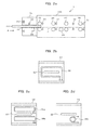
Figs. 2a to 2d are a side cross section and front views of the card reader; -
Fig. 3 is a plan view of a magnetic card; -
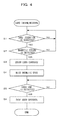
Fig. 4 is a flowchart illustrating operations at the time of card insertion in the card reader; -
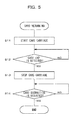
Fig. 5 is a flowchart illustrating operations at the time of returning a card in the card reader; -
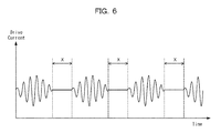
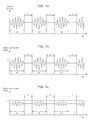
Fig. 6 is a waveform chart for describing a first embodiment; -
Figs. 7a to 7c are waveform charts for describing a second embodiment; -
Figs. 8a and 8b are waveform charts for describing a third embodiment; -
Figs. 9a and 9b are waveform charts for describing a fourth embodiment; -
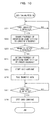
Fig. 10 is a flowchart for describing the operations of the fourth embodiment; -
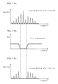
Figs. 11a to 11c are diagrams illustrating frequency spectra and a filter characteristic for describing the fifth embodiment; -
Figs. 12a to 12c are waveform charts expressing an interfering magnetic field, a magnetic stripe detection signal, and a synthesized signal of them; and -
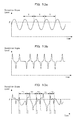
Figs. 13a to 13c are waveform charts for describing a sixth embodiment. - Hereinafter, embodiments of the present invention will be described with reference to the drawings.
- First, a configuration of a card reader according to a first embodiment will be described with reference to
Fig. 1 andFigs. 2a to 2d . - As illustrated in
Fig. 1 , acard reader 1 according to the present embodiment has acontrol unit 2 including a CPU for controlling the operations of the entire device, a magneticinformation reading unit 3 for reading magnetic data recorded in a magnetic card, acard carrying unit 4 for carrying a magnetic card, acard detection sensor 5 for detecting a magnetic card, amemory 6 for storing magnetic data read by the magneticinformation reading unit 3, a host interface 7 as a connection with a host device (for example, ATM), a magneticstripe detecting unit 10 for detecting a magnetic stripe of a magnetic card, and a magneticfield generating unit 8 for generating an interfering magnetic field to prevent reading of data recorded in the magnetic stripe. - The
control unit 2 includes a magneticfield control unit 9 for controlling the magneticfield generating unit 8 and a cardcarriage control unit 12 for controlling thecard carrying unit 4. The magneticstripe detecting unit 10 and the magneticfield generating unit 8 are disposed in a cardinsertion port unit 24. The magneticstripe detecting unit 10 includes a magnetic head 34 (Fig. 2a ) which will be described later. The magneticfield generating unit 8 includes a loop antenna 35 (Fig. 2b ) which will be described later. - As illustrated in
Fig. 2a , the cardinsertion port unit 24 is provided in the front face of acasing 100 of thecard reader 1. In the cardinsertion port unit 24, aninsertion port 22 in which a magnetic card (hereinbelow, simply called a "card") 21 is to be inserted is formed. As illustrated inFig. 3 , thecard 21 has amagnetic stripe 21a.Fig. 3 is a rear view of thecard 21. Near theinsertion port 22, a cardinsertion detection sensor 23 for detecting thecard 21 inserted is provided. The cardinsertion detection sensor 23 is a pressure sensor and disposed in a position where it is pressed by thecard 21 inserted through theinsertion port 22. Themagnetic head 34 for detecting a magnetic stripe is also provided near theinsertion port 22. Themagnetic head 34 detects themagnetic stripe 21a of thecard 21. - In the
casing 100 of thecard reader 1,carrier rollers 25 to 28, cardposition detection sensors 30 to 33, and amagnetic head 29 are provided. Each of thecarrier rollers 25 to 28 consists of a pair of rollers disposed on the upper and lower sides of a carrier path P, and thecard 21 is carried while being sandwiched by the pair of rollers. Thecarrier rollers 25 to 28 are coupled to a motor (not illustrated) via a carrier belt (not illustrated). One of a pair of carrier rollers is a drive roller to which the rotational force of the motor is transmitted, and the other roller is a driven roller which rotates in accordance with the drive roller. Thecarrier rollers 25 to 28 construct the card carrying unit 4 (Fig. 1 ) together with the carrier belt and the motor. - Each of the card
position detection sensors 30 to 33 is an optical sensor of the transmission type and has a light emitting unit and a light receiving unit which are opposed to each other across the carrier path P. The arrangement interval of thesensors 30 to 33 is shorter than the length in the carriage direction of themagnetic card 21. Thesensor 30 detects that thecard 21 is sandwiched by thecarrier rollers 25 which are closest to theinsertion port 22. Thesensor 33 detects that the insertedcard 21 reaches a storage part (not illustrated) temporarily storing a card. Thesensors card 21 being carried. The cardposition detection sensors 30 to 33 construct the card detection sensor 5 (Fig. 1 ) together with the cardinsertion detection sensor 23. - The
magnetic head 29 is provided on the lower side of the carrier path P between thecarrier rollers 26 and thecarrier rollers 27. Themagnetic head 29 reads data recorded in themagnetic stripe 21a of thecard 21 in the process of carriage of the insertedcard 21 in the carrier path P. Themagnetic head 34 is a magnetic head for detecting the existence of data recorded in a magnetic stripe whereas themagnetic head 29 is a magnetic head for reproducing data itself recorded in the magnetic stripe. The interval between themagnetic head 29 and thesensor 33 is slightly longer than the length in the carriage direction of thecard 21. Therefore, when thecard 21 reaches the storage part, that is, when the front end of thecard 21 reaches the position of thesensor 33, themagnetic head 29 completes reading of the data recorded in thecard 21. - The
loop antenna 35 is provided near the front face of the cardinsertion port unit 24. As understood fromFig. 2a , theloop antenna 35 is provided closer to theinsertion port 22 side than themagnetic head 34 for detecting a magnetic stripe in the insertion direction A of thecard 21 near theinsertion port 22. Theloop antenna 35 is an antenna obtained by winding a conductor once or a plurality of times in a loop shape and is disposed so as to surround theinsertion port 22 as illustrated inFig. 2b . - When drive current flows in the
loop antenna 35 in the magneticfield generating unit 8 based on control of the magneticfield control unit 9, theloop antenna 35 generates a magnetic field around theinsertion port 22. The magnetic field acts as an interfering magnetic field on themagnetic head 34 for detecting a magnetic stripe on the rear side of theinsertion port 22 and disturbs reading of magnetic information in themagnetic head 34. In addition, the magnetic field is generated also on the outside (front side) of theinsertion port 22 and, in the case where an illegal reader (not illustrated) is attached to the outside of theinsertion port 22, disturbs reading of magnetic information by the illegal reader. - Next, the basic operation of the
card reader 1 having the above configuration will be described with reference to flowcharts ofFigs. 4 and5 . -
Fig. 4 illustrates the procedure in the case of taking and reading thecard 21 at the time of card insertion. The process in each of steps is executed by thecontrol unit 2. It is assumed that theloop antenna 35 generates an interfering magnetic field also in a state where thecard 21 is not inserted in theinsertion port 22. - First, the
control unit 2 determines whether or not insertion of thecard 21 is detected by the card insertion detection sensor 23 (step S1). When insertion of thecard 21 is not detected (NO in step S1), thecontrol unit 2 repeatedly executes the step S1 and waits until insertion of thecard 21 is detected. When insertion of thecard 21 is detected (YES in step S1), thecontrol unit 2 determines whether or not a magnetic stripe is detected by the magneticstripe detecting unit 10, that is, whether or not magnetic data is read from themagnetic stripe 21a of thecard 21 by themagnetic head 34 for detecting a magnetic stripe (step S2). When the magnetic stripe is not detected (NO in step S2), thecontrol unit 2 determines that thecard 21 is not a magnetic card or is a magnetic card in which no data is recorded in a magnetic stripe, and returns to step S1. - When a magnetic stripe is detected (YES in step S2), the
control unit 2 determines that thecard 21 in which magnetic data is recorded is inserted, and rotates thecarrier rollers 25 to 28 by the cardcarriage control unit 12 to start carriage of the card 21 (step S3). At this time, thecarrier rollers 25 to 28 rotate in the direction of taking the insertedcard 21 into the casing 100 (hereinbelow, called a "forward direction"). Thus, thecard 21 passes through the carrier path P and is taken in thecasing 100. In the process of carrying thecard 21 in the carrier path P, magnetic data recorded in themagnetic stripe 21a of thecard 21 is read by the magnetic head 29 (step S4). - Subsequently, the
control unit 2 determines whether or not thesensor 33 disposed next to thecarrier roller 28 detects the end (the right end inFig. 2a ) of the card 21 (step S5). When thesensor 33 does not detect the card end (NO in step S5), thecontrol unit 2 repeatedly executes the step S5. Specifically, thecontrol unit 2 rotates thecarrier rollers 25 to 28 in the forward direction and continues carriage of thecard 21 until the card end is detected. When thesensor 33 detects the card end (YES in step S5), thecontrol unit 2 determines that the carriedcard 21 reaches the rear end of the carrier path P and stops the rotation of thecarrier rollers 25 to 28 by the cardcarriage control unit 12 to stop the carriage of the card 21 (step S6). At this time, thecard 21 is temporarily stored in the storage part (not illustrated). Thus, the series of all of processes ofFig. 4 is finished. -
Fig. 5 illustrates the procedure of the case of returning thecard 21. The process in each of steps is executed by thecontrol unit 2. - First, the
control unit 2 rotates thecarrier rollers 25 to 28 by the cardcarriage control unit 12 to start carriage of the card 21 (step S11). At this time, thecarriage rollers 25 to 28 rotate in the direction of carrying the insertedcard 21 from the storage part to the insertion port 22 (hereinbelow, called a "reverse direction"). Consequently, thecard 21 is carried in the carrier path P toward theinsertion port 22. At this time as well, the interfering magnetic field is generated by theloop antenna 35. - Subsequently, the
control unit 2 determines whether or not thesensor 30 disposed next to thecarrier roller 25 detects the end (the right end inFig. 2a ) of the card 21 (step S12). When thesensor 30 does not detect the card end (NO in step S12), thecontrol unit 2 repeatedly executes the step S12. Specifically, thecontrol unit 2 rotates thecarrier rollers 25 to 28 in the reverse direction and continues carriage of thecard 21 until the card end is detected. - When the
sensor 30 detects the card end (YES in step S12), thecontrol unit 2 determines that the carriedcard 21 is returned to theinsertion port 22 and stops the rotation of thecarrier rollers 25 to 28 by the cardcarriage control unit 12 to cease carrying the card 21 (step S13). At this time, as illustrated inFig. 2a , thecard 21 is sandwiched by the upper andlower carrier rollers 25, and the end portion of the card projects to the outside from theinsertion port 22. Consequently, a user can hold the endportion of thecard 21 projected from theinsertion port 22 and pull thecard 21 out. - Then the
control unit 2 determines whether or not the extraction of thecard 21 is detected by the card insertion detection sensor 23 (step S14). In a state where the cardinsertion detection sensor 23 detects the card, thecontrol unit 2 determines that thecard 21 is not pulled out (NO in step S14), repeatedly executes the step S14, and waits until thecard 21 is pulled out. When the cardinsertion detection sensor 23 changes from the card detection state to a state where the card is not detected, thecontrol unit 2 determines that thecard 21 is pulled out (YES in step S14) and finishes the process. Thus, the series of all of processes inFig. 5 is finished. - Next, a skimming measure as a feature of the present invention will be described.
Fig. 6 is a timing chart of magnetic stripe detection executed in step S2 in the flowchart ofFig. 4 . In the present embodiment, a pause period X is provided in the interfering magnetic field generated by the magneticfield generating unit 8, and data of the magnetic stripe is read in the pause period X. - Concretely, based on control of the magnetic
field control unit 9, drive current as illustrated inFig. 6 is passed through theloop antenna 35. The drive current is an alternating current signal having a predetermined oscillation frequency and the pause period X in which oscillation stops periodically. Consequently, the interfering magnetic field is generated intermittently from theloop antenna 35. In the pause period X, the magneticstripe detecting unit 10 reads data recorded in themagnetic stripe 21a of thecard 21 by themagnetic head 34 and outputs the result as a magnetic stripe detection signal. - Since the interfering magnetic field acts on the
magnetic head 34 for detecting a magnetic stripe while the interfering magnetic field is generated by theloop antenna 35, themagnetic head 34 cannot read magnetic data of thecard 21. Therefore, even if the skimming of the second type of coupling a lead wire to the output terminal of the magneticstripe detecting unit 10 and reading magnetic data of thecard 21 by an illegal reader via the lead wire is performed, the magnetic data of thecard 21 cannot be taken in the interfering magnetic field generation periods (the periods other than X). - On the other hand, in the interfering magnetic field pause period X, in the case where the skimming of the second type is performed, the magnetic data of the
card 21 can be read by an illegal reader. However, since the pause period X is actually an extremely short time, data read by the illegal reader during the period is just a piece of the magnetic data of thecard 21. Consequently, the original data recorded in themagnetic stripe 21a of thecard 21 cannot be restored from the data read by the illegal reader. - Moreover, the data read from the
magnetic stripe 21a by themagnetic head 34 in the pause period X is also a very small part of the magnetic data of thecard 21. However, themagnetic head 34 is a magnetic head for detecting a magnetic stripe but is not a magnetic head for reproducing magnetic data, so that it is sufficient to detect whether or not magnetic data is recorded in themagnetic stripe 21a. Therefore, even if the data read by themagnetic head 34 in the pause period X is a part of the original data, there is no problem in determination of the existence of data in themagnetic stripe 21a. - As described above, in the first embodiment, the interfering magnetic field generated by the
loop antenna 35 is acted on themagnetic head 34 for detecting a magnetic stripe, and data in themagnetic stripe 21a of thecard 21 is read by themagnetic head 34 during the interfering magnetic field pause period. Consequently, even if an illegal reader is attached to the output terminal of the magneticstripe detecting unit 10 via a lead wire, a signal output from the magneticstripe detecting unit 10 during the pause period X is a signal (a part of original data) by which only determination of the existence of data in themagnetic stripe 21a can be performed but is not a signal by which the data recorded in themagnetic stripe 21a can be completely reproduced. Therefore, illegal data acquisition by the skimming of the second type can be prevented. By making the interfering magnetic field of theloop antenna 35 act also on the outside of theinsertion port 22, illegal data acquisition by the skimming of the first type of attaching an illegal reader to the outside of theinsertion port 22 can be also prevented. - Moreover, since the
loop antenna 35 is provided closer to theinsertion port 22 side than themagnetic head 34 in the insertion direction A of thecard 21, magnetic data of thecard 21 is not read by themagnetic head 34 before the interfering magnetic field acts. Thus, the illegal data acquisition by the skimming of the second type can be prevented more effectively. - Next, a second embodiment of the present invention will be described. Note that, a configuration of a card reader in the second embodiment is the same as that in
Fig. 1 andFigs. 2a to 2d , and therefore, the description thereof will not be given. Also, the basic operation of the card reader is the same as that ofFigs. 4 and5 , and therefore, the description thereof will not be given. -
Figs. 7a to 7c are timing charts of magnetic stripe detection executed in step S2 in the flowchart ofFig. 4 . In the foregoing first embodiment, themagnetic head 34 performs the reading operation only during the pause periods X of the interfering magnetic field. In the second embodiment, themagnetic head 34 performs the reading operation also in the periods other than the pause periods X. - Concretely, based on control of the magnetic
field control unit 9, the drive current as illustrated inFig. 7a is passed through theloop antenna 35. The drive current is the same as the drive current (Fig. 6 ) in the first embodiment. In the pause periods X of the interfering magnetic field, then, the magneticstripe detecting unit 10 reads data recorded in themagnetic stripe 21a of thecard 21 by themagnetic head 34 and outputs the result as a magnetic stripe detection signal. - On the other hand, also in interfering magnetic field generation periods W (periods other than X), the
magnetic head 34 continues the reading operation. Consequently, a reception signal of a level according to the intensity of the magnetic field received by themagnetic head 34 is output from the magneticstripe detecting unit 10. Then, in the periods W, thecontrol unit 2 determines whether or not the interfering magnetic field generated by theloop antenna 35 is normally received by themagnetic head 34 based on the level of the reception signal output from the magneticstripe detecting unit 10. - In this case, as illustrated in
Figs. 7b and 7c , a reference level α is set for the reception signal level. Then, as illustrated inFig. 7b , in the case where the reception signal level is equal to or higher than α, thecontrol unit 2 determines that the interfering magnetic field is normally received by themagnetic head 34. On the other hand, as illustrated inFig. 7c , in the case where the reception signal level is less than α, thecontrol unit 2 determines that the interfering magnetic field is not normally received by themagnetic head 34 and something abnormal occurs in the magneticfield generating unit 8 or the magneticfield control unit 9. Thecontrol unit 2 then transmits an alarm signal to a host device (not illustrated) via the host interface 7 (Fig. 1 ). The host device receives the alarm signal and performs a predetermined process such as display of abnormality occurrence. - As described above, in the second embodiment, by making the interfering magnetic field acted on the
magnetic head 34 and reading data of thecard 21 by themagnetic head 34 during the interfering magnetic field pause period, a measure against skimming similar to that of the first embodiment can be performed. Further, by monitoring the level of an output signal of the magneticstripe detecting unit 10 during the periods other than the pause periods, the quality of the reception state of the interfering magnetic field in themagnetic head 34 can be determined. - Next, a third embodiment of the present invention will be described. Note that, a configuration of a card reader in the third embodiment is the same as that in
Fig. 1 andFigs. 2a to 2d , and therefore, the description thereof will not be given. Also, the basic operation of the card reader is the same as that ofFigs. 4 and5 , and therefore, the description thereof will not be given. -
Figs. 8a and 8b are timing charts of magnetic stripe detection executed in step S2 in the flowchart ofFig. 4 . Although the pause periods X are provided for the interfering magnetic field in the foregoing first embodiment, in the third embodiment, periods Y in which the frequency changes are provided for the interfering magnetic field. - Concretely, based on control of the magnetic
field control unit 9, drive current as illustrated inFig. 8a is passed through theloop antenna 35. The drive current is an alternating current signal having a predetermined oscillation frequency and the period Y in which the frequency changes periodically (here in below, called "frequency change period"). That is, in the periods other than Y, the frequency of the drive current is f1 (first frequency) . In the frequency change period Y, the frequency of the drive current changes from f1 to f2 (second frequency). Although f1 < f2 is satisfied here, f1 > f2 is also possible. - In the frequency change period Y, the magnetic
stripe detecting unit 10 reads data recorded in themagnetic stripe 21a of thecard 21 by themagnetic head 34. The magneticstripe detecting unit 10 performs a filtering process for eliminating the signal having the frequency f2 on the read data and outputs a signal after the filtering as a magnetic stripe detection signal. As a result, from the magneticstripe detecting unit 10, a signal obtained by eliminating the signal having the frequency f2 in the frequency change period Y as illustrated inFig. 8b is output. - In the present embodiment, the interfering magnetic field generated by the
loop antenna 35 always acts on themagnetic head 34. Consequently, even if the skimming of the second type of coupling a lead wire to the output terminal of the magneticstripe detecting unit 10 and reading magnetic data of thecard 21 by an illegal reader via the lead wire is performed, the magnetic data of thecard 21 cannot be taken. - On the other hand, in the frequency change periods Y in which the frequency of the interfering magnetic field changes, a signal output from the magnetic
stripe detecting unit 10 becomes different from that of the original data recorded in thecard 21 by the filtering process. As described above, however, it is sufficient that themagnetic head 34 can detect the existence of magnetic data in themagnetic stripe 21a and it is unnecessary to reproduce the magnetic data. Further, when magnetic data is recorded in themagnetic stripe 21a, themagnetic head 34 reads the data. As a result, a signal which does not include the frequency f2 is output from the magneticstripe detecting unit 10 in the frequency change period Y, so that the existence of magnetic data can be determined by the signal. Since the signal is a signal by which only determination of the existence of data in themagnetic stripe 21a can be performed, even if the signal is read in the frequency change period Y by the skimming of the second type, the original data cannot be reproduced. - As described above, in the third embodiment, by making the interfering magnetic field acted on the
magnetic head 34 and reading the data of thecard 21 by themagnetic head 34 in a period of a specific frequency while changing the frequency of the interfering magnetic field, a measure against skimming similar to that in the first embodiment can be performed. Since the interfering magnetic field always acts on themagnetic head 34, a measure against an illegal act can be performed more reliably. - Next, a fourth embodiment of the present invention will be described. Note that, a configuration of a card reader in the fourth embodiment is the same as that in
Fig. 1 andFigs. 2a to 2d , and therefore, the description thereof will not be given. - In the present embodiment, the
loop antenna 35 always generates an interfering magnetic field having a random frequency (first frequency) and, when insertion of themagnetic card 21 is detected, switches the random frequency to the constant frequency (second frequency). - Concretely, as illustrated in
Fig. 9a , in the period Z1 until timing t1 at which insertion of thecard 21 is detected, based on control of the magneticfield control unit 9, the drive current having the random frequency flows in theloop antenna 35, and theloop antenna 35 generates the interfering magnetic field having the random frequency. Then, when insertion of thecard 21 is detected by the cardinsertion detection sensor 23 at the timing t1, based on the control of the magneticfield control unit 9, the frequency of the drive current flowing in theloop antenna 35 is switched from the random frequency to the constant frequency fo, and theloop antenna 35 generates the interfering magnetic field having the constant frequency fo for the predetermined period Z2. - In the period Z2 in which the frequency of the interfering magnetic field is constant, the magnetic
stripe detecting unit 10 reads data recorded in themagnetic stripe 21a of thecard 21 by themagnetic head 34. The magneticstripe detecting unit 10 then performs a filtering process for eliminating the signal having the frequency fo on the read data and outputs a signal after the filtering as a magnetic stripe detection signal. As a result, from the magneticstripe detecting unit 10, a signal obtained by eliminating the signal having the frequency fo in the period Z2 as illustrated inFig. 9b is output. - When the detection of a magnetic stripe by the magnetic
stripe detecting unit 10 is finished at timing t2, based on the control of the magneticfield control unit 9, the frequency of the drive current flowing in theloop antenna 35 switches from the constant frequency fo to the random frequency. In the following period Z3, the interfering magnetic field having random frequency is generated again from theloop antenna 35. -
Fig. 10 illustrates the procedure in the case of performing take-in and reading of thecard 21 in the fourth embodiment. The process in each of steps is executed by thecontrol unit 2. - First, the
control unit 2 determines whether or not insertion of thecard 21 is detected by the card insertion detection sensor 23 (step S21). When insertion of thecard 21 is not detected (NO in step S21), thecontrol unit 2 repeatedly executes step S21 and waits until insertion of thecard 21 is detected. When insertion of thecard 21 is detected (YES in step S21), the magneticfield control unit 9 controls the magneticfield generating unit 8 to change the frequency of the interfering magnetic field generated by theloop antenna 35 from random frequency to constant frequency (step S22). Moreover, from this time point, the magneticstripe detecting unit 10 starts detection of a magnetic stripe. - Next, the
control unit 2 determines whether or not a magnetic stripe is detected by the magneticstripe detecting unit 10, that is, whether or not magnetic data is read from themagnetic stripe 21a of thecard 21 by themagnetic head 34 for detecting a magnetic stripe (step S23). When no magnetic stripe is detected (NO in step S23), thecontrol unit 2 determines that thecard 21 is not a magnetic card or is a magnetic card in which no data is recorded in a magnetic stripe, and returns to step S21. - When a magnetic stripe is detected (YES in step S23), the magnetic
field control unit 9 controls the magneticfield generating unit 8 to return the frequency of the interfering magnetic field generated by theloop antenna 35 to random frequency (step S24). Thecontrol unit 2 determines that thecard 21 in which magnetic data is recorded is inserted and rotates thecarrier rollers 25 to 28 in the forward direction by the cardcarriage control unit 12 to start carriage of the card 21 (step S25). Thus, thecard 21 passes through the carrier path P and is taken in thecasing 100. In the process that thecard 21 is carried in the carrier path P, magnetic data recorded in themagnetic stripe 21a of thecard 21 is read by the magnetic head 29 (step S26). - Subsequently, the
control unit 2 determines whether or not thesensor 33 disposed next to thecarrier roller 28 detects the end (the right end inFig. 2a ) of the card 21 (step S27). When thesensor 33 does not detect the card end (NO in step S27), thecontrol unit 2 repeatedly executes the step S27. Specifically, thecontrol unit 2 rotates thecarrier rollers 25 to 28 in the forward direction and continues carriage of thecard 21 until the card end is detected. When thesensor 33 detects the card end (YES in step S27), thecontrol unit 2 determines that the carriedcard 21 has reached the rear end of the carrier path P and stops the rotation of thecarrier rollers 25 to 28 by the cardcarriage control unit 12 to cease carrying the card 21 (step S28). At this time, thecard 21 is temporarily stored in the storage part (not illustrated). Thus, the series of all of processes ofFig. 10 is finished. Note that, the operation at the time of returning the card is the same as that inFig. 5 , and therefore, the description thereof will not be given. - Also in the fourth embodiment, in a manner similar to the third embodiment, since the interfering magnetic field generated by the
loop antenna 35 always acts on themagnetic head 34, even if the skimming of the second type of coupling a lead wire to the output terminal of the magneticstripe detecting unit 10 and reading magnetic data of thecard 21 by an illegal reader via the lead wire is performed, the magnetic data of thecard 21 cannot be taken. - On the other hand, in the period Z2 in which the frequency of the interfering magnetic field is constant, a signal output from the magnetic
stripe detecting unit 10 becomes different from that of original data recorded in thecard 21 by the filtering process. However, in a manner similar to the third embodiment, if magnetic data is recorded in themagnetic stripe 21a, themagnetic head 34 reads the data. As a result, in the period Z2, a signal which does not include the frequency fo is output from the magneticstripe detecting unit 10. Hence, by this signal, the existence of magnetic data can be determined. Since the above signal is a signal by which only determination of the existence of data in themagnetic stripe 21a can be performed, even if the signal is read in the period Z2 by the skimming of the second type, the original data cannot be reproduced. - As described above, in the fourth embodiment, by normally making the interfering magnetic field having random frequency acted on the
magnetic head 34, on detection of insertion of thecard 21, setting the frequency of the interfering magnetic field to the constant frequency fo, and reading the data of thecard 21 by themagnetic head 34, a measure against skimming similar to that in the first embodiment can be performed. Since the interfering magnetic field always acts on themagnetic head 34, a measure against an illegal act can be performed more reliably. - Next, a fifth embodiment of the present invention will be described. Note that, the configuration of a card reader in the fifth embodiment is the same as that in
Fig. 1 andFigs. 2a to 2d , and therefore, the description thereof will not be given. Also, the basic operation of the card reader is the same as that inFigs. 4 and5 , and therefore, the description thereof will not be given. - In the foregoing first to fourth embodiments, the interfering magnetic field generated by the
loop antenna 35 is changed only in a specific period to a state different from that in the other period. In the fifth embodiment, without changing the state of the interfering magnetic field, the magneticstripe detecting unit 10 performs a filtering process for eliminating a signal having a frequency which is in the same band as that of the frequency of the interfering magnetic field on data read from themagnetic stripe 21a by themagnetic head 34. The detailed description will be given below. -
Fig. 11a illustrates the frequency spectrum of a reception signal in the magneticstripe detecting unit 10 in the case of superimposing the interfering magnetic field of theloop antenna 35 on magnetic data of thecard 21 and reading the resultant by themagnetic head 34. Assume that a reception signal in a state where only the interfering magnetic field exists and no magnetic data exists is a signal as illustrated inFig. 12a , and a reception signal in a state where the interfering magnetic field does not exist and only magnetic data exists is a signal as illustrated inFig. 12b . A reception signal of themagnetic stripe detectingunit 10 in a state where the interfering magnetic field is superimposed on magnetic data will be a signal as illustrated inFig. 12c , which is obtained by combining the signal ofFig. 12a and the signal ofFig. 12b . Consequently, the reception signal includes a wide frequency component as illustrated inFig. 11a . -
Fig. 11b illustrates the characteristic of a filter provided for the magneticstripe detecting unit 10. The filter eliminates a specific frequency component, that is, a frequency component in the same band as that of the frequency of the interfering magnetic field from the reception signal having the frequency spectrum ofFig. 11a. Fig. 11c illustrates the frequency spectrum obtained by performing a filtering process on the reception signal of the magneticstripe detecting unit 10 by a filter having the characteristic ofFig. 11b . As understood fromFig. 11c , a part of the frequency component in the same band as that of the interfering magnetic field is eliminated from the reception signal by the filtering process. - Also in the fifth embodiment, in a manner similar to the third and fourth embodiments, since the interfering magnetic field generated by the
loop antenna 35 always acts on themagnetic head 34, even if the skimming of the second type of coupling a lead wire to the output terminal of the magneticstripe detecting unit 10 and reading magnetic data of thecard 21 by an illegal reader via the lead wire is performed, the magnetic data of thecard 21 cannot be taken. - On the other hand, due to the filtering process described above, in the magnetic
stripe detecting unit 10, a part of the magnetic data of thecard 21 is lost from the reception signal. However, since the frequency of the reception signal lies in a wide range as illustrated inFig. 11a , all of the magnetic data is not lost. Therefore, by a signal output from the magneticstripe detecting unit 10 based on residual data, the existence of magnetic data can be determined. Since the output signal is a signal by which only determination of the existence of data in themagnetic stripe 21a can be performed, even if the signal is read by the skimming of the second type, the original data cannot be reproduced. - As described above, in the fifth embodiment, by making the interfering magnetic field acted on the
magnetic head 34 and performing a filtering process for eliminating a frequency component which is in the same band as that of the frequency of the interfering magnetic field on a reception signal of the magneticstripe detecting unit 10, a measure against skimming similar to that of the first embodiment can be performed. Further, since the interfering magnetic field always acts on themagnetic head 34, a measure against an illegal act can be performed more reliably. Moreover, since the state of the interfering magnetic field is not changed, the control in the magneticfield control unit 9 is simplified. - Next, a sixth embodiment of the present invention will be described. Note that, the configuration of a card reader in the sixth embodiment is the same as that in
Fig. 1 andFigs. 2a to 2d , and therefore, the description thereof will not be given. Also, the basic operation of the card reader is the same as that inFigs. 4 and5 , and therefore, the description thereof will not be given. - In the sixth embodiment, without changing the state of the interfering magnetic field, magnetic stripe detection is performed by monitoring whether or not the frequency of a detection signal output from the magnetic
stripe detecting unit 10 shifts with respect to the frequency of the interfering magnetic field. The detailed description will be given below. -
Figs. 13a to 13c illustrate the waveforms of the reception signals of the magneticstripe detecting unit 10.Fig. 13a is the waveform of a reception signal by the interfering magnetic field,Fig. 13b is the waveform of a reception signal by magnetic data of thecard 21, andFig. 13c is the waveform of a reception signal in a state where the interfering magnetic field is superimposed on magnetic data.Figs. 13a to 13c are similar toFigs. 12a to 12c , respectively. - As illustrated in
Fig. 13a , a predetermined threshold β is set with respect to the level of a reception signal by the interfering magnetic field. In a state where themagnetic card 21 is not inserted, thecontrol unit 2 detects time T from the rising edge of a reception signal to the next rising edge thereof at the threshold β. The time T corresponds to the frequency of the interfering magnetic field generated by theloop antenna 35 and is constant. - As illustrated in
Fig. 13c , the same threshold β is set for a reception signal in a state where the interfering magnetic field is superimposed on magnetic data. When themagnetic card 21 is inserted and themagnetic stripe 21a is detected in a state where the interfering magnetic field is generated, the signal ofFig. 13c is output as a detection signal from the magneticstripe detecting unit 10. Thecontrol unit 2 detects time from the rising edge of a reception signal at the threshold β to the next rising edge thereof. The time corresponds to the frequency of the detection signal and varies like T1 to T5. That is, the frequency of the detection signal shifts from the frequency of the interfering magnetic field. - Based on the time T detected in
Fig. 13a and the times T1 to T5 detected inFig. 13c , thecontrol unit 2 then determines whether or not the frequency of the detection signal output from the magneticstripe detecting unit 10 shifts from the frequency of the interfering magnetic field and, in the case where the frequency of the detection signal shifts, determines that themagnetic card 21 in which magnetic data is recorded in themagnetic stripe 21a is inserted. - Note that, in the present embodiment, although the magnetic
stripe detecting unit 10 outputs the signal ofFig. 13c as it is as a detection signal, the magneticstripe detecting unit 10 may generate a pulse signal (indicated by broken line) at the rising edge of a reception signal at the threshold β and output the pulse signal to thecontrol unit 2 as the detection signal. - Also in the sixth embodiment, since the interfering magnetic field generated by the
loop antenna 35 always acts on themagnetic head 34, even if the skimming of the second type of coupling a lead wire to the output terminal of the magneticstripe detecting unit 10 and reading magnetic data of thecard 21 by an illegal reader via the lead wire is performed, the magnetic data of thecard 21 cannot be taken. - On the other hand, although a detection signal output from the magnetic
stripe detecting unit 10 becomes different from that of original data recorded in thecard 21, the existence of magnetic data can be determined by detecting the frequency fluctuation as described above. Since this detection signal is a signal by which only determination of the existence of data in themagnetic stripe 21a can be performed, even if the signal is read by the skimming of the second type, the original data cannot be reproduced. - As described above, in the sixth embodiment, by making the interfering magnetic field acted on the
magnetic head 34 and performing the magnetic stripe detection based on a fluctuation in the frequency of the output signal of the magneticstripe detecting unit 10 with respect to the frequency of the interfering magnetic field, a measure against skimming similar to that in the first embodiment can be performed. Since the interfering magnetic field always acts on themagnetic head 34, a measure against an illegal act can be performed more reliably. Further, since the state of the interfering magnetic field is not changed, in a manner similar to the case of the fifth embodiment, the control in the magneticfield control unit 9 is simplified. - In each of the foregoing embodiments, a measure against skimming in the case where the
card 21 is inserted was described. On the other hand, as a measure against skimming in the case where thecard 21 is returned, it is sufficient to continuously generate the interfering magnetic field from theloop antenna 35. The reason is that the magnetic stripe detection is performed to open a shutter (not illustrated) of theinsertion port 22 at the time of insertion of thecard 21 but is not performed when thecard 21 is returned, so that it is unnecessary to control pause or the like of the interfering magnetic field. - In each of the foregoing embodiments, a measure against skimming to the
magnetic head 34 for detecting a magnetic stripe was described. On the other hand, in thecasing 100 of thecard reader 1, themagnetic head 29 for reading themagnetic stripe 21a and reproducing the data exists (seeFig. 2a ). As a measure against skimming to themagnetic head 29, for example, a measure of encrypting data read by themagnetic head 29 or the like is taken. - In each of the foregoing embodiments, an example of disposing one
loop antenna 35 so as to surround theinsertion port 22 as illustrated inFig. 2b was mentioned. In place of this, as illustrated inFig. 2c , twoindependent loop antennas insertion port 22. The number of loop antennas may be three or more. In the case of providing a plurality of loop antennas, a stronger interfering magnetic field can be generated as compared with the case of providing a single loop antenna, so that skimming can be prevented more effectively. Interfering magnetic fields of different frequencies may be generated by a plurality of loop antennas. In such a manner, the interfering magnetic fields acting on an illegal reader have a plurality of frequency components, so that it becomes difficult to eliminate the interfering magnetic fields even by performing a filtering process and illegal data acquisition can be prevented more reliably. Further, as illustrated inFig. 2d , asingle loop antenna 35c may be disposed only near themagnetic head 34 for detecting a magnetic stripe (Fig. 2a ). - By disposing a core made of metal such as ferrite or iron having high magnetic permeability for the loop antenna, the magnetic field can have directivity or a stronger interfering magnetic field can be generated.
- In each of the foregoing embodiments, as a magnetic recording medium, the magnetic card having the magnetic stripe on its rear surface was described as an example. However, the present invention can be also applied to a magnetic recording medium reading device handling a magnetic card having a magnetic stripe on the surface or both surface and rear surface.
- In each of the foregoing embodiments, a magnetic card was described as a magnetic recording medium. However, the present invention can be also applied to a device for reading, not limited to a magnetic card but, a magnetic recording medium such as a passbook having a magnetic stripe.
- The present invention can be applied to devices for reading a magnetic recording medium such as a card reader and a passbook reader installed on an automatic transaction processing device such as an ATM, or a card reader installed in a card verifying terminal.
-
- 1
- card reader
- 2
- control unit
- 8
- magnetic field generating unit
- 9
- magnetic field control unit
- 10
- magnetic stripe detecting unit
- 21
- magnetic card
- 21a
- magnetic stripe
- 22
- insertion port
- 34
- magnetic head
- 35
- loop antenna
Claims (9)
- A magnetic recording medium reading device (1) comprising:aninsertionport (22) in which a magnetic recording medium (21) is to be inserted;a magnetic stripe detecting unit (10) including a magnetic head (34) that detects a magnetic stripe (21a) of the magnetic recording medium (21);a magnetic field generating unit (8) that generates an interfering magnetic field to disturb reading of data recorded in the magnetic stripe (21a) of the magnetic recording medium (21); anda control unit (2) that determines the existence of data recorded in the magnetic stripe (21a) based on a detection signal output from the magnetic stripe detecting unit (10),characterized in that the magnetic field generating unit (8) is provided near the insertion port (22) and makes the interfering magnetic field acted on the magnetic head (34), andin the case where the magnetic field generating unit (8) generates an interfering magnetic field and the magnetic recording medium (21) is inserted through the insertion port (22), the magnetic stripe detecting unit (10) outputs a detection signal by which only determination of the existence of data recorded in the magnetic stripe (21a) can be performed.
- The magnetic recording medium reading device (1) according to claim 1, wherein the magnetic field generating unit (8) is provided closer to the insertion port (22) side than the magnetic head (34) in an insertion direction of the magnetic recording medium (21).
- The magnetic recording medium reading device(1)according to claim 1 or 2, wherein the magnetic field generating unit (8) changes the interfering magnetic field only for a specific period to a state different from that in the other period, and
the magnetic stripe detecting unit (10) reads data in the magnetic stripe (21a) by the magnetic head (34) and outputs the detection signal in the specific period. - The magnetic recording medium reading device(1)according to claim 3, wherein the specific period is a pause period in which the interfering magnetic field pauses.
- The magnetic recording medium reading device(1)according to claim 4, wherein the control unit (2) determines whether or not the interfering magnetic field generated by the magnetic field generating unit (8) is normally received by the magnetic head (34) based on a level of a signal output from the magnetic stripe detecting unit (10) in a period other than the pause period.
- The magnetic recording medium reading device(1)according to claim 3, wherein the frequency of the interfering magnetic field is a first frequency in the period other than the specific period,
the frequency of the interfering magnetic field is changed to a second frequency in the specific period, and
the magnetic stripe detecting unit (10) performs a filtering process for eliminating a signal having the second frequency on data read from the magnetic stripe (21a) by the magnetic head (34). - The magnetic recording medium reading device(1)according to claim 6, wherein the first frequency is a random frequency, and the second frequency is a constant frequency.
- The magnetic recording medium reading device(1)according to claim 1 or 2, wherein the magnetic stripe detecting unit (10) performs a filtering process for eliminating a signal having a frequency in the same band as that of the frequency of the interfering magnetic field on data read from the magnetic stripe (21a) by the magnetic head (34), and outputs a signal subjected to the filtering process as the detection signal.
- The magnetic recording medium reading device (1) according to claim 1 or 2, wherein the control unit (2) determines whether or not the frequency of the detection signal output from the magnetic stripe detecting unit (10) shifts with respect to the frequency of the interfering magnetic field and, in the case where the frequency of the detection signal shifts, the control unit (2) determines that a magnetic recording medium (21) in which data is recorded in a magnetic stripe (21a) is inserted.
Applications Claiming Priority (1)
| Application Number | Priority Date | Filing Date | Title |
|---|---|---|---|
| PCT/JP2010/007428 WO2012085967A1 (en) | 2010-12-22 | 2010-12-22 | Apparatus for reading magnetic recording medium |
Publications (3)
| Publication Number | Publication Date |
|---|---|
| EP2657888A1 true EP2657888A1 (en) | 2013-10-30 |
| EP2657888A4 EP2657888A4 (en) | 2015-08-19 |
| EP2657888B1 EP2657888B1 (en) | 2020-02-12 |
Family
ID=46313274
Family Applications (1)
| Application Number | Title | Priority Date | Filing Date |
|---|---|---|---|
| EP10860934.8A Active EP2657888B1 (en) | 2010-12-22 | 2010-12-22 | Apparatus for reading magnetic recording medium |
Country Status (5)
| Country | Link |
|---|---|
| EP (1) | EP2657888B1 (en) |
| JP (1) | JP5629330B2 (en) |
| KR (1) | KR101388121B1 (en) |
| CN (1) | CN103210402B (en) |
| WO (1) | WO2012085967A1 (en) |
Cited By (1)
| Publication number | Priority date | Publication date | Assignee | Title |
|---|---|---|---|---|
| EP3217369A1 (en) * | 2016-03-08 | 2017-09-13 | LG CNS Co., Ltd. | Financial device and method of controlling financial device |
Families Citing this family (14)
| Publication number | Priority date | Publication date | Assignee | Title |
|---|---|---|---|---|
| JP6193056B2 (en) * | 2013-08-27 | 2017-09-06 | Necプラットフォームズ株式会社 | Information protection apparatus, information protection program, and information protection method |
| JP6218524B2 (en) * | 2013-09-18 | 2017-10-25 | 日本電産サンキョー株式会社 | Magnetic recording medium processing apparatus and method for controlling magnetic recording medium processing apparatus |
| JP2015108954A (en) * | 2013-12-04 | 2015-06-11 | Necプラットフォームズ株式会社 | Card reader, automatic transaction device, control method, and program |
| JP2015197687A (en) * | 2014-03-31 | 2015-11-09 | 日本電産サンキョー株式会社 | Magnetic field generator, magnetic recording medium processing apparatus, and control method of magnetic recording medium processing apparatus |
| JP6178759B2 (en) * | 2014-07-08 | 2017-08-09 | 日本電産サンキョー株式会社 | Card reader |
| JP6211498B2 (en) * | 2014-09-26 | 2017-10-11 | 日本電産サンキョー株式会社 | Card reader and card reader control method |
| JP6377542B2 (en) * | 2015-01-26 | 2018-08-22 | 日立オムロンターミナルソリューションズ株式会社 | Card processing device |
| JP2016189055A (en) | 2015-03-30 | 2016-11-04 | 日本電産サンキョー株式会社 | Card reader |
| JP6417264B2 (en) * | 2015-04-17 | 2018-11-07 | 日立オムロンターミナルソリューションズ株式会社 | Card insertion / discharge unit, card processing apparatus and automatic transaction apparatus |
| JP6492984B2 (en) * | 2015-06-03 | 2019-04-03 | 沖電気工業株式会社 | Automatic transaction equipment |
| JP2017045174A (en) * | 2015-08-25 | 2017-03-02 | 沖電気工業株式会社 | Transaction device |
| JP7178846B2 (en) * | 2018-09-26 | 2022-11-28 | 日本電産サンキョー株式会社 | Magnetic recording media processor |
| JP2020113357A (en) * | 2019-01-17 | 2020-07-27 | 日本電産サンキョー株式会社 | Magnetic recording medium processor and control method |
| JP6680931B2 (en) * | 2019-05-16 | 2020-04-15 | 日本電産サンキョー株式会社 | Magnetic field generator, magnetic field generator control method, and magnetic recording medium processing apparatus |
Family Cites Families (13)
| Publication number | Priority date | Publication date | Assignee | Title |
|---|---|---|---|---|
| US6574058B1 (en) * | 1998-11-24 | 2003-06-03 | Sankyo Seiki Mfg. Co., Ltd. | Recording medium detecting apparatus for distinguishing between a recording medium having a relatively high coercivity or a relatively low coercivity |
| JP3806271B2 (en) * | 1999-07-09 | 2006-08-09 | 日本電産サンキョー株式会社 | Magnetic card transaction device |
| JP3936496B2 (en) | 1999-08-31 | 2007-06-27 | 日本電産サンキョー株式会社 | Magnetic card transaction device |
| JP2002074607A (en) * | 2000-08-30 | 2002-03-15 | Sankyo Seiki Mfg Co Ltd | Card reader |
| JP4401119B2 (en) * | 2003-08-27 | 2010-01-20 | 日立オムロンターミナルソリューションズ株式会社 | IC card processing device |
| JP4425674B2 (en) | 2004-03-17 | 2010-03-03 | 日立オムロンターミナルソリューションズ株式会社 | Magnetic card reader |
| DE102005043317B3 (en) * | 2005-09-12 | 2007-04-12 | Wincor Nixdorf International Gmbh | Method and device for generating an electromagnetic protective field for a card reader |
| JP4644592B2 (en) * | 2005-12-14 | 2011-03-02 | 日立オムロンターミナルソリューションズ株式会社 | Card processing device and data processing device |
| AT507034B1 (en) * | 2008-06-18 | 2010-04-15 | Keba Ag | METHOD AND DEVICE FOR PROTECTING A READER FOR CARDBOARD DATA AGAINST THE UNAUTHORIZED EVALUATION OR COPYING OF MAGNETICALLY-CODED DATA OF AN ADDED CARDBOARD DATA SUPPORT |
| JP5728791B2 (en) * | 2009-03-05 | 2015-06-03 | 日本電産サンキョー株式会社 | Card reader |
| DE102009019708B4 (en) * | 2009-05-05 | 2012-12-20 | synfis Beteiligungen GmbH | Device for protecting a card reading device, automaton hereby |
| DE102010000102A1 (en) * | 2010-01-18 | 2011-07-21 | WINCOR NIXDORF International GmbH, 33106 | Self-service machine i.e. automatic teller machine, has interference signal separating device provided such that total signal is processed to determine desired signal, which supports reading of desired data from magnetic stripe card |
| JP5705516B2 (en) * | 2010-11-30 | 2015-04-22 | 日本電産サンキョー株式会社 | Card reader |
-
2010
- 2010-12-22 EP EP10860934.8A patent/EP2657888B1/en active Active
- 2010-12-22 JP JP2012549478A patent/JP5629330B2/en active Active
- 2010-12-22 CN CN201080070194.2A patent/CN103210402B/en not_active Expired - Fee Related
- 2010-12-22 KR KR1020137008711A patent/KR101388121B1/en active Active
- 2010-12-22 WO PCT/JP2010/007428 patent/WO2012085967A1/en not_active Ceased
Cited By (2)
| Publication number | Priority date | Publication date | Assignee | Title |
|---|---|---|---|---|
| EP3217369A1 (en) * | 2016-03-08 | 2017-09-13 | LG CNS Co., Ltd. | Financial device and method of controlling financial device |
| US9978223B2 (en) | 2016-03-08 | 2018-05-22 | Lg Cns Co., Ltd. | Financial device and method of controlling financial device |
Also Published As
| Publication number | Publication date |
|---|---|
| CN103210402A (en) | 2013-07-17 |
| EP2657888A4 (en) | 2015-08-19 |
| EP2657888B1 (en) | 2020-02-12 |
| JPWO2012085967A1 (en) | 2014-05-22 |
| JP5629330B2 (en) | 2014-11-19 |
| KR20130069792A (en) | 2013-06-26 |
| CN103210402B (en) | 2016-06-08 |
| KR101388121B1 (en) | 2014-04-23 |
| WO2012085967A1 (en) | 2012-06-28 |
Similar Documents
| Publication | Publication Date | Title |
|---|---|---|
| EP2657888B1 (en) | Apparatus for reading magnetic recording medium | |
| CN103733231B (en) | Magnetic recording media reading device | |
| CN100576268C (en) | card processing device | |
| CN102982613B (en) | Magnetic reader | |
| EP2752823B1 (en) | Device for reading magnetic recording medium | |
| US8397991B2 (en) | Protective device and method for preventing skimming on a card reader | |
| US20090159676A1 (en) | Method for generating a protective electromagnetic field for a card reading device | |
| WO2012073691A1 (en) | Magnetic head and card reader | |
| WO2017193887A1 (en) | Anti-skimming electromagnetic interference detection method and device | |
| CN106062872A (en) | Card reader | |
| EP2320352B1 (en) | Card processing apparatus and data reading device | |
| JP5695204B2 (en) | Magnetic recording medium reader | |
| JP2015108954A (en) | Card reader, automatic transaction device, control method, and program | |
| US20190340395A1 (en) | Card reader device | |
| JP4977746B2 (en) | Card processing device | |
| WO2015097913A1 (en) | Magnetic reader device provided with magnetic interference loop antenna |
Legal Events
| Date | Code | Title | Description |
|---|---|---|---|
| PUAI | Public reference made under article 153(3) epc to a published international application that has entered the european phase |
Free format text: ORIGINAL CODE: 0009012 |
|
| 17P | Request for examination filed |
Effective date: 20130722 |
|
| AK | Designated contracting states |
Kind code of ref document: A1 Designated state(s): AL AT BE BG CH CY CZ DE DK EE ES FI FR GB GR HR HU IE IS IT LI LT LU LV MC MK MT NL NO PL PT RO RS SE SI SK SM TR |
|
| DAX | Request for extension of the european patent (deleted) | ||
| RA4 | Supplementary search report drawn up and despatched (corrected) |
Effective date: 20150722 |
|
| RIC1 | Information provided on ipc code assigned before grant |
Ipc: G07D 9/00 20060101ALI20150716BHEP Ipc: G07F 7/12 20060101ALI20150716BHEP Ipc: G06K 17/00 20060101AFI20150716BHEP |
|
| STAA | Information on the status of an ep patent application or granted ep patent |
Free format text: STATUS: EXAMINATION IS IN PROGRESS |
|
| 17Q | First examination report despatched |
Effective date: 20181206 |
|
| GRAP | Despatch of communication of intention to grant a patent |
Free format text: ORIGINAL CODE: EPIDOSNIGR1 |
|
| STAA | Information on the status of an ep patent application or granted ep patent |
Free format text: STATUS: GRANT OF PATENT IS INTENDED |
|
| INTG | Intention to grant announced |
Effective date: 20190710 |
|
| GRAS | Grant fee paid |
Free format text: ORIGINAL CODE: EPIDOSNIGR3 |
|
| GRAA | (expected) grant |
Free format text: ORIGINAL CODE: 0009210 |
|
| STAA | Information on the status of an ep patent application or granted ep patent |
Free format text: STATUS: THE PATENT HAS BEEN GRANTED |
|
| AK | Designated contracting states |
Kind code of ref document: B1 Designated state(s): AL AT BE BG CH CY CZ DE DK EE ES FI FR GB GR HR HU IE IS IT LI LT LU LV MC MK MT NL NO PL PT RO RS SE SI SK SM TR |
|
| REG | Reference to a national code |
Ref country code: GB Ref legal event code: FG4D |
|
| REG | Reference to a national code |
Ref country code: CH Ref legal event code: EP |
|
| REG | Reference to a national code |
Ref country code: AT Ref legal event code: REF Ref document number: 1233110 Country of ref document: AT Kind code of ref document: T Effective date: 20200215 |
|
| REG | Reference to a national code |
Ref country code: IE Ref legal event code: FG4D |
|
| REG | Reference to a national code |
Ref country code: DE Ref legal event code: R096 Ref document number: 602010063109 Country of ref document: DE |
|
| REG | Reference to a national code |
Ref country code: NL Ref legal event code: FP |
|
| PG25 | Lapsed in a contracting state [announced via postgrant information from national office to epo] |
Ref country code: RS Free format text: LAPSE BECAUSE OF FAILURE TO SUBMIT A TRANSLATION OF THE DESCRIPTION OR TO PAY THE FEE WITHIN THE PRESCRIBED TIME-LIMIT Effective date: 20200212 Ref country code: FI Free format text: LAPSE BECAUSE OF FAILURE TO SUBMIT A TRANSLATION OF THE DESCRIPTION OR TO PAY THE FEE WITHIN THE PRESCRIBED TIME-LIMIT Effective date: 20200212 Ref country code: NO Free format text: LAPSE BECAUSE OF FAILURE TO SUBMIT A TRANSLATION OF THE DESCRIPTION OR TO PAY THE FEE WITHIN THE PRESCRIBED TIME-LIMIT Effective date: 20200512 |
|
| REG | Reference to a national code |
Ref country code: LT Ref legal event code: MG4D |
|
| PG25 | Lapsed in a contracting state [announced via postgrant information from national office to epo] |
Ref country code: BG Free format text: LAPSE BECAUSE OF FAILURE TO SUBMIT A TRANSLATION OF THE DESCRIPTION OR TO PAY THE FEE WITHIN THE PRESCRIBED TIME-LIMIT Effective date: 20200512 Ref country code: IS Free format text: LAPSE BECAUSE OF FAILURE TO SUBMIT A TRANSLATION OF THE DESCRIPTION OR TO PAY THE FEE WITHIN THE PRESCRIBED TIME-LIMIT Effective date: 20200612 Ref country code: GR Free format text: LAPSE BECAUSE OF FAILURE TO SUBMIT A TRANSLATION OF THE DESCRIPTION OR TO PAY THE FEE WITHIN THE PRESCRIBED TIME-LIMIT Effective date: 20200513 Ref country code: SE Free format text: LAPSE BECAUSE OF FAILURE TO SUBMIT A TRANSLATION OF THE DESCRIPTION OR TO PAY THE FEE WITHIN THE PRESCRIBED TIME-LIMIT Effective date: 20200212 Ref country code: LV Free format text: LAPSE BECAUSE OF FAILURE TO SUBMIT A TRANSLATION OF THE DESCRIPTION OR TO PAY THE FEE WITHIN THE PRESCRIBED TIME-LIMIT Effective date: 20200212 Ref country code: HR Free format text: LAPSE BECAUSE OF FAILURE TO SUBMIT A TRANSLATION OF THE DESCRIPTION OR TO PAY THE FEE WITHIN THE PRESCRIBED TIME-LIMIT Effective date: 20200212 |
|
| PG25 | Lapsed in a contracting state [announced via postgrant information from national office to epo] |
Ref country code: SK Free format text: LAPSE BECAUSE OF FAILURE TO SUBMIT A TRANSLATION OF THE DESCRIPTION OR TO PAY THE FEE WITHIN THE PRESCRIBED TIME-LIMIT Effective date: 20200212 Ref country code: SM Free format text: LAPSE BECAUSE OF FAILURE TO SUBMIT A TRANSLATION OF THE DESCRIPTION OR TO PAY THE FEE WITHIN THE PRESCRIBED TIME-LIMIT Effective date: 20200212 Ref country code: EE Free format text: LAPSE BECAUSE OF FAILURE TO SUBMIT A TRANSLATION OF THE DESCRIPTION OR TO PAY THE FEE WITHIN THE PRESCRIBED TIME-LIMIT Effective date: 20200212 Ref country code: LT Free format text: LAPSE BECAUSE OF FAILURE TO SUBMIT A TRANSLATION OF THE DESCRIPTION OR TO PAY THE FEE WITHIN THE PRESCRIBED TIME-LIMIT Effective date: 20200212 Ref country code: PT Free format text: LAPSE BECAUSE OF FAILURE TO SUBMIT A TRANSLATION OF THE DESCRIPTION OR TO PAY THE FEE WITHIN THE PRESCRIBED TIME-LIMIT Effective date: 20200705 Ref country code: DK Free format text: LAPSE BECAUSE OF FAILURE TO SUBMIT A TRANSLATION OF THE DESCRIPTION OR TO PAY THE FEE WITHIN THE PRESCRIBED TIME-LIMIT Effective date: 20200212 Ref country code: RO Free format text: LAPSE BECAUSE OF FAILURE TO SUBMIT A TRANSLATION OF THE DESCRIPTION OR TO PAY THE FEE WITHIN THE PRESCRIBED TIME-LIMIT Effective date: 20200212 Ref country code: ES Free format text: LAPSE BECAUSE OF FAILURE TO SUBMIT A TRANSLATION OF THE DESCRIPTION OR TO PAY THE FEE WITHIN THE PRESCRIBED TIME-LIMIT Effective date: 20200212 Ref country code: CZ Free format text: LAPSE BECAUSE OF FAILURE TO SUBMIT A TRANSLATION OF THE DESCRIPTION OR TO PAY THE FEE WITHIN THE PRESCRIBED TIME-LIMIT Effective date: 20200212 |
|
| REG | Reference to a national code |
Ref country code: DE Ref legal event code: R097 Ref document number: 602010063109 Country of ref document: DE |
|
| REG | Reference to a national code |
Ref country code: AT Ref legal event code: MK05 Ref document number: 1233110 Country of ref document: AT Kind code of ref document: T Effective date: 20200212 |
|
| PLBE | No opposition filed within time limit |
Free format text: ORIGINAL CODE: 0009261 |
|
| STAA | Information on the status of an ep patent application or granted ep patent |
Free format text: STATUS: NO OPPOSITION FILED WITHIN TIME LIMIT |
|
| 26N | No opposition filed |
Effective date: 20201113 |
|
| PG25 | Lapsed in a contracting state [announced via postgrant information from national office to epo] |
Ref country code: IT Free format text: LAPSE BECAUSE OF FAILURE TO SUBMIT A TRANSLATION OF THE DESCRIPTION OR TO PAY THE FEE WITHIN THE PRESCRIBED TIME-LIMIT Effective date: 20200212 Ref country code: AT Free format text: LAPSE BECAUSE OF FAILURE TO SUBMIT A TRANSLATION OF THE DESCRIPTION OR TO PAY THE FEE WITHIN THE PRESCRIBED TIME-LIMIT Effective date: 20200212 |
|
| PG25 | Lapsed in a contracting state [announced via postgrant information from national office to epo] |
Ref country code: PL Free format text: LAPSE BECAUSE OF FAILURE TO SUBMIT A TRANSLATION OF THE DESCRIPTION OR TO PAY THE FEE WITHIN THE PRESCRIBED TIME-LIMIT Effective date: 20200212 Ref country code: SI Free format text: LAPSE BECAUSE OF FAILURE TO SUBMIT A TRANSLATION OF THE DESCRIPTION OR TO PAY THE FEE WITHIN THE PRESCRIBED TIME-LIMIT Effective date: 20200212 |
|
| REG | Reference to a national code |
Ref country code: CH Ref legal event code: PL |
|
| PG25 | Lapsed in a contracting state [announced via postgrant information from national office to epo] |
Ref country code: MC Free format text: LAPSE BECAUSE OF FAILURE TO SUBMIT A TRANSLATION OF THE DESCRIPTION OR TO PAY THE FEE WITHIN THE PRESCRIBED TIME-LIMIT Effective date: 20200212 |
|
| REG | Reference to a national code |
Ref country code: BE Ref legal event code: MM Effective date: 20201231 |
|
| PG25 | Lapsed in a contracting state [announced via postgrant information from national office to epo] |
Ref country code: IE Free format text: LAPSE BECAUSE OF NON-PAYMENT OF DUE FEES Effective date: 20201222 Ref country code: LU Free format text: LAPSE BECAUSE OF NON-PAYMENT OF DUE FEES Effective date: 20201222 Ref country code: FR Free format text: LAPSE BECAUSE OF NON-PAYMENT OF DUE FEES Effective date: 20201231 |
|
| PG25 | Lapsed in a contracting state [announced via postgrant information from national office to epo] |
Ref country code: LI Free format text: LAPSE BECAUSE OF NON-PAYMENT OF DUE FEES Effective date: 20201231 Ref country code: CH Free format text: LAPSE BECAUSE OF NON-PAYMENT OF DUE FEES Effective date: 20201231 |
|
| PG25 | Lapsed in a contracting state [announced via postgrant information from national office to epo] |
Ref country code: TR Free format text: LAPSE BECAUSE OF FAILURE TO SUBMIT A TRANSLATION OF THE DESCRIPTION OR TO PAY THE FEE WITHIN THE PRESCRIBED TIME-LIMIT Effective date: 20200212 Ref country code: MT Free format text: LAPSE BECAUSE OF FAILURE TO SUBMIT A TRANSLATION OF THE DESCRIPTION OR TO PAY THE FEE WITHIN THE PRESCRIBED TIME-LIMIT Effective date: 20200212 Ref country code: CY Free format text: LAPSE BECAUSE OF FAILURE TO SUBMIT A TRANSLATION OF THE DESCRIPTION OR TO PAY THE FEE WITHIN THE PRESCRIBED TIME-LIMIT Effective date: 20200212 |
|
| REG | Reference to a national code |
Ref country code: NL Ref legal event code: HC Owner name: HITACHI CHANNEL SOLUTIONS, CORP.; JP Free format text: DETAILS ASSIGNMENT: CHANGE OF OWNER(S), CHANGE OF OWNER(S) NAME; FORMER OWNER NAME: HITACHI-OMRON TERMINAL SOLUTIONS, CORP. Effective date: 20220614 |
|
| PG25 | Lapsed in a contracting state [announced via postgrant information from national office to epo] |
Ref country code: MK Free format text: LAPSE BECAUSE OF FAILURE TO SUBMIT A TRANSLATION OF THE DESCRIPTION OR TO PAY THE FEE WITHIN THE PRESCRIBED TIME-LIMIT Effective date: 20200212 Ref country code: AL Free format text: LAPSE BECAUSE OF FAILURE TO SUBMIT A TRANSLATION OF THE DESCRIPTION OR TO PAY THE FEE WITHIN THE PRESCRIBED TIME-LIMIT Effective date: 20200212 |
|
| REG | Reference to a national code |
Ref country code: DE Ref legal event code: R081 Ref document number: 602010063109 Country of ref document: DE Owner name: HITACHI CHANNEL SOLUTIONS, CORP., JP Free format text: FORMER OWNER: HITACHI-OMRON TERMINAL SOLUTIONS, CORP., TOKYO, JP |
|
| PG25 | Lapsed in a contracting state [announced via postgrant information from national office to epo] |
Ref country code: BE Free format text: LAPSE BECAUSE OF NON-PAYMENT OF DUE FEES Effective date: 20201231 |
|
| PGFP | Annual fee paid to national office [announced via postgrant information from national office to epo] |
Ref country code: NL Payment date: 20251119 Year of fee payment: 16 |
|
| PGFP | Annual fee paid to national office [announced via postgrant information from national office to epo] |
Ref country code: DE Payment date: 20251126 Year of fee payment: 16 |
|
| PGFP | Annual fee paid to national office [announced via postgrant information from national office to epo] |
Ref country code: GB Payment date: 20251119 Year of fee payment: 16 |