EP2657886B1 - Method and apparatus for recognizing three-dimensional object - Google Patents
Method and apparatus for recognizing three-dimensional object Download PDFInfo
- Publication number
- EP2657886B1 EP2657886B1 EP13150632.1A EP13150632A EP2657886B1 EP 2657886 B1 EP2657886 B1 EP 2657886B1 EP 13150632 A EP13150632 A EP 13150632A EP 2657886 B1 EP2657886 B1 EP 2657886B1
- Authority
- EP
- European Patent Office
- Prior art keywords
- brightness
- image
- human face
- display unit
- lock function
- Prior art date
- Legal status (The legal status is an assumption and is not a legal conclusion. Google has not performed a legal analysis and makes no representation as to the accuracy of the status listed.)
- Not-in-force
Links
Images





Classifications
-
- G—PHYSICS
- G06—COMPUTING OR CALCULATING; COUNTING
- G06V—IMAGE OR VIDEO RECOGNITION OR UNDERSTANDING
- G06V10/00—Arrangements for image or video recognition or understanding
- G06V10/40—Extraction of image or video features
-
- G—PHYSICS
- G06—COMPUTING OR CALCULATING; COUNTING
- G06V—IMAGE OR VIDEO RECOGNITION OR UNDERSTANDING
- G06V40/00—Recognition of biometric, human-related or animal-related patterns in image or video data
- G06V40/40—Spoof detection, e.g. liveness detection
- G06V40/45—Detection of the body part being alive
-
- G—PHYSICS
- G06—COMPUTING OR CALCULATING; COUNTING
- G06F—ELECTRIC DIGITAL DATA PROCESSING
- G06F21/00—Security arrangements for protecting computers, components thereof, programs or data against unauthorised activity
- G06F21/30—Authentication, i.e. establishing the identity or authorisation of security principals
- G06F21/31—User authentication
-
- G—PHYSICS
- G06—COMPUTING OR CALCULATING; COUNTING
- G06V—IMAGE OR VIDEO RECOGNITION OR UNDERSTANDING
- G06V10/00—Arrangements for image or video recognition or understanding
- G06V10/10—Image acquisition
-
- G—PHYSICS
- G06—COMPUTING OR CALCULATING; COUNTING
- G06V—IMAGE OR VIDEO RECOGNITION OR UNDERSTANDING
- G06V10/00—Arrangements for image or video recognition or understanding
- G06V10/10—Image acquisition
- G06V10/12—Details of acquisition arrangements; Constructional details thereof
- G06V10/14—Optical characteristics of the device performing the acquisition or on the illumination arrangements
- G06V10/141—Control of illumination
Definitions
- the present invention relates to an apparatus for recognizing a three-dimensional object, and more particularly, to a method and an apparatus for recognizing a three-dimension object using a light source.
- the security function is a function which persons except for an owner of the portable terminal cannot use the portable terminal.
- a user may set a password for using the portable terminal.
- the portable terminal When power of the portable terminal is turned-off and then turned-off or when the portable terminal is switched from a sleep mode to an active state, the portable terminal provides a password input screen. If the user properly inputs a preset password, the portable terminal becomes a state which allows a user to use a function of the portable terminal such as a phone call or use of Internet. Conversely, if the user does not input the password, the portable terminal maintains a lock state. Before inputting a right password, the user cannot use the function of the portable terminal.
- a scheme using human body information such as iris recognition, fingerprint recognition, and face recognition schemes may be utilized.
- the user may previously input fingerprint/iris/face images.
- the portable terminal becomes a lock state.
- the user may provide fingerprint/iris/face images to the portable terminal through a camera of the portable terminal or other input means to release the lock state. If the portable terminal receives the same fingerprint/iris/face images as preset images, it may release the lock state.
- a face image received by the portable terminal is a two-dimensional image. It is assumed that an owner of the portable terminal previously inputs a face of the owner as security means. After that, when the portable terminal becomes a lock state, the owner of the portable terminal exposes the face of the owner to a camera of the portable terminal to release the lock state. Conversely, even if a face of a person other than the owner of the portable terminal is exposed to a camera of the portable terminal, the lock state is not released.
- US 2007/0110285 discloses apparatus and methods for determining whether a live, human eye is presented for iris-based recognition. An image is presented on a computer screen and reflected back from the eye. The reflected image is captured and processed to determine whether the reflection is consistent with a human eye.
- the present invention has been made in view of the above problems, and provides an apparatus for recognizing a three-dimension object not to avoid a security function using a two-dimension photograph, and a method thereof.
- a method of releasing of a lock function of a terminal including a display unit for displaying an operation state of the terminal and a shoot unit for receiving an image comprising a human face, the method comprising: receiving an input for commanding a lock function setting of the operational state of the terminal, the lock function setting comprising:
- an apparatus for recognizing an object as three-dimensional when using a security function includes: a display unit for displaying an operation state of a terminal; a shooting unit for receiving an image comprising an human face; an input unit for receiving an input from a user for commanding a lock function setting of operational state, and a further input for commanding a lock function releasing of the operation state; a controller configured to: in response to receiving an input for commanding a lock function setting, control the shooting unit to receive a first image of the human face by setting first brightness as brightness of the display unit, control the shooting unit to receive a second image of the human face by setting second brightness as the brightness of the display unit, wherein the second brightness is different to the first brightness, and compare the first and second images to extract an interest region having a brightness difference greater than a first threshold; in response to receiving an input for commanding a lock function release; control the shooting unit to receive a third image of the human face by setting a third brightness as brightness of the display unit, wherein the
- FIG. 1a is a block diagram illustrating a configuration of an apparatus 100 for recognizing a three-dimension object according to an exemplary embodiment of the present invention.
- the apparatus 100 for recognizing a three-dimension object according to an exemplary embodiment of the present invention include a radio frequency (RF) communication unit 110, an audio processor 120, a display unit 130, an input unit 140, a memory 150, a controller 160, and a shooting unit 170.
- RF radio frequency
- the RF communication unit 110 performs a transceiving function of corresponding data for wireless communication of the apparatus 100 for recognizing a three-dimension object.
- the RF communication unit 110 may include an RF transmitter for up-converting a frequency of a transmitted signal and amplifying the converted signal, and an RF receiver for low-noise-amplifying a received signal and down-converting the amplified signal.
- the RF communication unit 110 receives and outputs data through a wireless channel to the controller 160 and transmits data outputted from the controller 160. In a case of the apparatus 100 for recognizing a three-dimension object which does not support wireless communication, the RF communication unit 110 may be omitted.
- the audio processor 120 may be configured by a CODEC.
- the CODEC may include a data CODEC processing packet data and an audio CODEC processing an audio signal such as a voice.
- the audio processor 120 converts a digital audio signal into an analog audio signal through the audio CODEC and plays the converted analog audio signal through a speaker SPK.
- the audio processor 120 converts an analog audio signal inputted from a microphone MIC into a digital audio signal. In a case of the apparatus 100 for recognizing a three-dimension object which does not support audio processing, the audio processor 120 may be omitted.
- the input unit 140 receives an input of the user and transfers the input of the user to the controller 160.
- the input unit 140 may be implemented in the form of a touch sensor and/or a key pad.
- the touch sensor detects a touch input of the user.
- the touch sensor may be configured by a capacitive overlay sensor, a resistive overlay sensor, an infrared beam sensor, or a pressure sensor.
- Various types of sensor devices capable of detecting contact or pressure of an object may be configured as a touch sensor in addition to the foregoing sensors.
- the touch sensor detects a touch input of the user and generates and transmits a detection signal to the controller 160.
- the detection signal includes coordinates data which the user inputs the touch.
- the touch sensor When the user inputs a touch location moving operation, the touch sensor generates the detection signal including coordinates data of a touch location moving path to the controller 160.
- the key pad receives a key operation of the user for controlling the apparatus 100 for recognizing a three-dimension object and generates and transfers an input signal to the controller 160.
- the key pad may include numeric keys and arrow keys.
- the key pad may be provided in one side of the apparatus 100 for recognizing a three-dimension object as a predetermined function key.
- the display unit 130 visually provides a menu of the apparatus 100 for recognizing a three-dimension object, input data, function setting information and other various information to the user.
- the display unit 130 performs a function of outputting a booting screen, an idle screen, a menu screen, a call screen, and other application screens.
- the display unit 110 may be configured by a Liquid Crystal Display (LCD), an Organic Light Emitting Diode (OLED), and an Active Matrix Organic Light Emitting Diode (AMOLED).
- the display unit 130 performs a function of outputting a booting screen, an idle screen, a menu screen, a call screen, and other application screens of the apparatus 100 for recognizing a three-dimension object.
- the display unit 130 converts brightness of a screen into at least two brightness and provides the at least two brightness when performing an object recognition function for releasing the lock screen. If receiving an object image corresponding to at least two screen brightness, the shooting unit 170 may compare respective object images to recognize the objects.
- the memory 150 stores programs and data necessary for an operation of the apparatus 100 for recognizing a three-dimension object.
- the memory 130 may be divided into a program area and a data area.
- the program area may store a program controlling an overall operation of the apparatus 100 for recognizing a three-dimension object, an operating system booting the apparatus 100 for recognizing a three-dimension object, an application program necessary for playing multimedia contents, and an application program necessary for other option functions of the apparatus 100 for recognizing a three-dimension object, for example, a camera function, a sound playback function, and an image or moving image playback function.
- the data area may store data generated according to use of the apparatus 100 for recognizing a three-dimension object, images, moving pictures, phone-books, and audio data.
- the memory 150 may store an object (e.g., face) image for a lock function according to setting of the user or information obtained by processing the object image.
- an object e.g., face
- the shooting unit 170 shoots an image under the control of the controller 160.
- the shooting unit 170 has the same operation scheme or configuration as those of the related art, and thus the detailed description thereof is appropriately omitted.
- FIG. 1b is a front view of the apparatus 100 for recognizing a three-dimension object shown in FIG. 1a .
- a screen of the display unit 130 and a camera of the shooing unit 170 have to orient toward the same direction. That is, the screen of the display unit 130 and a lens of the shooting unit 170 should be disposed so that light emitted from the shooting unit 170 reaches an object for shooting and is again reflected from the shooting unit 170.
- the controller 160 controls an overall operation of respective constituent elements of the apparatus 100 for recognizing a three-dimension object.
- the controller 160 when receiving a lock function setting command, the controller 160 shoots a first image by setting first brightness to the display unit 130, and shoots a second image by again setting second brightness differing from the first brightness to the display unit 130.
- the controller 160 shoots a third image by setting third brightness to the display unit 130, and shoots a fourth image by again setting second brightness differing from the third brightness to the display unit 130.
- the third brightness may be the same as or differ from the first brightness.
- the fourth brightness may be the same as or differ from the second brightness.
- the controller 160 compares the second image with the first image, and compares the fourth image with the third image.
- the controller 160 may recognize a three-dimension object based on the comparison results.
- the controller 160 may control the shooting unit 170 to repeatedly shoot while increasing brightness of the display unit 130 from third brightness to limited brightness at preset speed or lower.
- the controller 160 may detect a direction of the object from the image and converts the image according thereto to recognize the three-dimension object.
- FIG. 2 is a flowchart illustrating a method of setting a lock function using three-dimension object recognition according to a first embodiment of the present invention.
- FIG. 3 is a flowchart illustrating a method of recognizing a three-dimension object according to a first embodiment of the present invention. A procedure of FIG. 3 may be performed after the procedure of FIG. 2 .
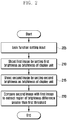
- An input unit 140 receives an input for commanding lock function setting start from the user (205).
- the user may command the lock function setting through a menu or other schemes. If receiving the input for commanding the lock function setting, the controller 160 may perform a procedure of setting a lock function as illustrated in steps 210 to 215.
- the controller 160 may shoot the first image by setting first brightness as brightness of the display unit 130 (210).
- the controller 160 may shoot the second image by setting second brightness as brightness of the display unit 130 (215).
- the second brightness should differ from the first brightness. The following embodiment will be described on the assumption that the second brightness is brighter than the first brightness.
- the controller 160 compares the second image with the first image to extract a region (interest region) having a brightness difference greater than a first threshold (threshold of interest region) (220).
- the first threshold may be a preset value.
- the first threshold may be set such that a predetermined part of entire regions becomes the interest region according to a brightness difference distribution in a comparison result of entire images. That is, to set the interest region to be 10% of entire regions, if there is 10 % of entire regions having a brightness difference greater than A, the threshold is A.
- FIG. 4 is an exemplary diagram illustrating a shot image of a shooting unit 170 according to a first embodiment of the present invention.
- a first image 410 is an image shooting a three-dimension object, for example, a human face by setting relatively dark brightness (first brightness).
- a second image 420 is an image shooting the human face by setting brightness (second brightness) brighter than that of the first image.
- a third image 430 is an image again shooting a two-dimension photograph outputting the human face by the shooting unit 170 by setting the third brightness to the display unit 130.
- the human face is the three-dimension object, if the display unit 130 emits strong light, the human face may reflect light from the display unit 130 more as compared with a protruding part such as forehead, eyes, cheekbone regions 425 or parts having special materials. Greater brightness change on the regions 425 is observed as compared with other regions.
- the two-dimension photograph relatively uniformly reflects light of the display unit 130. There is no brightness change in an image 430 again shooting the two-dimension photograph except that a central part of a photograph relatively adjacent to a center of the display unit 130 shines brightly.
- a region 425 having great brightness change may be extracted according to a stereoscopic characteristic or a material characteristic.
- the region is referred to as 'interest region'.
- a lock release operation may be performed in a scheme of FIG. 3 .
- a controller 160 receives a lock release command (305). For example, when the apparatus 100 for recognizing a three-dimension object is switched from a sleep mode to an active mode or power of the apparatus 100 for recognizing a three-dimension object is turned-off and then turned-on, the controller 160 may receive the lock release command. When receiving a command for performing an operation requiring other security, for example, initialization or a function such as private information reading included in the apparatus, the controller 160 may receive the lock release command. When receiving the lock release command, the controller 160 may perform steps 310 and next steps. Although the lock release procedure is illustrated, steps 310 and next steps may be performed for an operation requiring other face recognition or object recognition.
- the controller 160 may shoot a third image by setting a third brightness as brightness of the display unit 130 (310).
- the controller 160 may shoot a fourth image by setting a fourth brightness as brightness of the display unit 130 (315). It is assumed that the third brightness is the same as the first brightness. However, in another embodiment, the third brightness may differ from the first brightness. It is assumed that the fourth brightness is the same as the second brightness. However, in another embodiment, the fourth brightness may differ from the second brightness.
- An image displayed on the display unit 130 at steps 310 and 315 may be an image in which a full screen is similar to white. Accordingly, radiating effect of light through the display unit 130 may be maximized.
- an image displayed through the display unit 130 may be set according to a selection input of the user. A procedure of setting an image displayed through the display unit 130 may be performed in addition to a setting procedure of FIG. 2 .
- the controller 160 determines whether the third image is the same as, that is, accords with the first image (320). Determination of the identity/according of the image does not determine whether the third image is physically the same as the first image but an object of the third image is substantially the same as the first image. That is, if the third image accords with the first image by suitably correcting or converting the first image and the third image, the controller 160 determines that the third image is the same as the first image.
- the foregoing embodiment has illustrated that the third image is compared with the first image, the fourth image may be compared with the second image, the third image is compared with the second image, or the fourth image may be compared with the first image.
- the controller 160 determines that three-dimension object recognition fails (325). That is, the controller 160 determines that a lock release attempt performed through steps 310 and 315 is a lock release attempt of a user which is not authenticated, and maintains a lock state.
- the process goes to step 330.
- the controller 160 compares the fourth image with the third image in the region extracted at step 220, that is, an interest region (330). As the comparison result of the third and fourth images, when a brightness difference of the interest region is equal to or greater than a second preset threshold (recognition threshold), the controller 160 determines that a currently shot object is the same as an object set in the procedure of FIG. 2 . As the comparison result of the third and fourth images, when a brightness difference of the interest region is equal to or greater than a second preset threshold (recognition threshold), the controller 160 determines that a currently shot object differs from then object set in the procedure of FIG. 2 .
- the second preset threshold may be less than the first threshold (threshold of interest region) of FIG.
- the second threshold is very large, it may not be determined that a shot object is the same as a preset object. If the second threshold is very small, a case of shooting a two-dimension photograph may not be filtered. Accordingly, it may be preferable that the second threshold is slightly smaller than the first threshold.
- a concrete threshold may be experimentally determined so that erroneous recognition is minimized.
- the controller 160 may perform a step of determining that object recognition fails regardless of step 330.
- An artificial illumination is applied to increase the brightness difference greater than a predetermined value to prevent a security function from being incapacitated.
- FIG. 5 is a flowchart illustrating a method of recognizing a three-dimension object according to a second embodiment of the present invention. It is assumed that a lock function is set according to a procedure of FIG. 2 in the second embodiment.
- a controller 160 receives a command starting a lock release operation (505). Then, the controller 160 shoots a third image by setting third brightness as brightness of the display unit 130 (510). The third brightness may be the same value as that of the first brightness. The controller 160 determines whether the third image is the same as the first image (515). Since a determination procedure of the identity of the image is similar to a procedure of step 320, a detailed description thereof is omitted. When the third image differs from the first image, the controller 160 determines that the object recognition fails (520). That is, the lock state is not released. When the third image is the same as the first image, the process goes to step 525.
- the controller 160 shoots a fourth image by increasing brightness of the display unit 130 by a predetermined amount (525).
- the increased brightness amount of the display unit 130 is limited to less than a preset value.
- the user may show action, for example, momentarily feels discomfort, makes a wry face, or closes eyes. Accordingly, it does make the display unit 130 to be bright at excessively high speed.
- the controller 160 recognizes the object by comparing the fourth image with the third image in the interest region at step 220 (530).
- the object recognition procedure of step 530 is the same/similar as step 330 of FIG. 3 , and thus the detailed description thereof is appropriately omitted.
- the controller 160 determines whether object recognition succeeds (535). When the object recognition succeeds, a lock state is released and the process is terminated. When the object recognition does not succeed, the process goes to step 540.
- the controller 160 determines whether the brightness of the display unit 130 reaches preset limited brightness, that is, is equal to or greater than the limited brightness (540). When the brightness of the display unit 130 reaches the limited brightness, the controller 160 determines that the object recognition fails (520). Accordingly, the lock state is not released. When the brightness of the display unit 130 does not reach the limited brightness, the process returns to step 525. When the object recognition succeeds or until the brightness of the display unit 130 reaches the limited brightness, steps 525 to 540 may be repeatedly performed.
- face recognition may be efficiently performed while reducing discomfort of the user in a scheme of repeating shooting by slowly increasing the brightness of the display unit 130.
- the apparatus 100 for recognizing a three-dimension object may include an illumination sensor.
- the controller 160 may set start brightness of the display unit 130 according to a peripheral illumination value measured by the illumination sensor. That is, when the peripheral illumination is relatively bright, the start brightness of the display unit 130 may be set brighter. Conversely, when the peripheral illumination is relatively dark, the start brightness of the display unit 130 may be set darker.
- the controller 160 may shoot a third image when the brightness of the display unit 130 reaches the third brightness of step 510 while slowly increasing the brightness of the display unit 130, and perform following operations.
- FIG. 6 is a flowchart illustrating a method of recognizing a three-dimension object according to a third embodiment of the present invention.
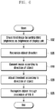
- a controller 160 shoots a third image by setting third brightness as brightness of a display unit 130 (602).
- Step 602 is the same as step 310 of FIG. 3 , and thus the detailed description thereof is appropriately omitted.
- the controller 160 recognizes a direction of an object based on the third image (605).
- FIG. 7 is a diagram illustrating recognition of a three-dimension object according to a third embodiment of the present invention.
- a first screen 710 is an image shooting a face from the bottom.
- a second screen 720 is an image shooting a face from a front side.
- a third screen 730 is an image shooting a face from the top. Referring to FIG. 7 , as the object is located away from the shooting unit 170, the object is shot smaller, and accordingly a whole shape of the face is differently expressed.
- An upper portion and a lower portion of the face in the first screen 710 are shown smaller and larger as the second screen 720.
- a lower portion and an upper portion of the face in the third screen 730 are shown smaller and larger as the second screen 720. Accordingly, if an object direction is normally recognized, erroneous recognition may be prevented.
- the apparatus 100 for recognizing a three-dimension object may include at least one of a geomagnetic sensor/acceleration sensor/gyro sensor.
- the controller 160 may a direction of the apparatus 100 for recognizing a three-dimension object using the geomagnetic sensor/acceleration sensor/gyro sensor.
- the apparatus 100 may recognize a relative direction of the face and other objects using the direction of the apparatus 100.
- the apparatus 100 for recognizing a three-dimension object may recognize a direction of an object using disposal of a characteristic part of a three-dimension object indicated on the third image.
- a direction of the object may be determined based on a disposed form of a characteristic part such as eyes or a mouse.
- a characteristic part such as eyes or a mouse.
- the controller 160 may determine that the object is shot from the bottom.
- a direction of the object may be recognized through a disposal of a characteristic part of the face.
- the direction of the object may be recognized using information of the geomagnetic sensor/acceleration sensor/gyro sensor and disposal of a characteristic part in a shot image.
- the controller 160 converts an image according to the recognized direction of the object (610). For example, when it is recognized that the object is shot from the bottom, image correction may be performed according to a perspective in such a way that a size of a lower part is converted small and the size of the upper part is converted large.
- the controller 160 adjusts a threshold for recognition according to a direction of an object (620). As illustrated referring to FIG. 3 , when a brightness difference of an interest region is equal to or greater than a recognition threshold, the controller 160 determines that a shot object is the same as a preset object. However, since the brightness difference may be changed according to a shot direction, the controller 160 reflects this. For example, when the face is shot from the bottom (710), the controller 160 may control a recognition threshold of an interest region corresponding to a forehead located in an upper side of the face or eyes smaller. This is why the forehead and eyes cannot normally receive and reflect light of the display unit 130 because the forehead and eyes are distant from the display unit 130.
- the controller 160 may control a recognition threshold of an interest region corresponding to a forehead located in an upper side of the face or eyes larger. This is why the forehead and eyes cannot receive and reflect light of the display unit 130 because the forehead and eyes are near to the display unit 130.
- the controller 160 recognizes the object through the procedure of FIG. 3 (625).
- the fourth image of step 315 may be converted in an object recognition procedure in the same manner in the third image.
- the procedure of FIG. 3 is equally applicable except for image conversion according to the direction of the object and control of the threshold.
- a procedure of FIG. 5 is applicable instead of the procedure of FIG. 3 .
- the instructions of a computer program may be mounted in a computer or a programmable data processing equipment, a series of operation stages are executed on the computer or the programmable data processing equipment to produce a process executed by the computer such that the instructions executing the computer or the programmable data processing equipment may provide stages for executing functions described in flowchart block(s).
- each block may indicate a part of a module including at least one executable instruction for executing specific logical function(s), a segment, and a code.
- functions mentioned in blocks may be created beyond an order. Two sequentially shown blocks may be performed really and simultaneously or be performed in a reverse order according to a corresponding function.
- the term ' ⁇ unit' means a software, or a hardware structural element such as FPGA or ASIC, and performs some functions.
- ' ⁇ unit' is not limited to the software or hardware.
- a ' ⁇ unit' may be configured in an addressable storing medium to play at least one processor.
- ' ⁇ unit' includes software structural elements, object-oriented software structural elements, class structural elements, task structural elements, processes, functions, attributes, procedures, sub-routines, segments of a program code, drivers, firmware, micro code, circuit, data, database, data structures, tables, arrays, and variables.
- Functions provided to structural elements and ' ⁇ units may be combined by a smaller number of structural elements and ' ⁇ unit's or divided into additional structural elements and ' ⁇ units.
- structural elements and ' ⁇ unit's may be implemented to play at least one CPU in a device or security multimedia card.
- the embodiment of the present invention represents an effect which may provide an apparatus and a method for recognizing a three-dimension object to prevent a security function from being incapacitated using a two-dimension photograph.
Landscapes
- Engineering & Computer Science (AREA)
- Theoretical Computer Science (AREA)
- Physics & Mathematics (AREA)
- General Physics & Mathematics (AREA)
- Multimedia (AREA)
- Computer Security & Cryptography (AREA)
- Human Computer Interaction (AREA)
- Computer Hardware Design (AREA)
- Software Systems (AREA)
- General Engineering & Computer Science (AREA)
- Image Analysis (AREA)
- Studio Devices (AREA)
- Length Measuring Devices By Optical Means (AREA)
Description
- The present invention relates to an apparatus for recognizing a three-dimensional object, and more particularly, to a method and an apparatus for recognizing a three-dimension object using a light source.
- In recent years, use of a portable terminal such as a portable tablet PC has been increased. Accordingly, a request for a security function of the portable terminal has been increased. The security function is a function which persons except for an owner of the portable terminal cannot use the portable terminal.
- According to a password input scheme known in the art, a user may set a password for using the portable terminal. When power of the portable terminal is turned-off and then turned-off or when the portable terminal is switched from a sleep mode to an active state, the portable terminal provides a password input screen. If the user properly inputs a preset password, the portable terminal becomes a state which allows a user to use a function of the portable terminal such as a phone call or use of Internet. Conversely, if the user does not input the password, the portable terminal maintains a lock state. Before inputting a right password, the user cannot use the function of the portable terminal.
- As other similar schemes, a scheme using human body information such as iris recognition, fingerprint recognition, and face recognition schemes may be utilized. The user may previously input fingerprint/iris/face images. Next, when power is turned-off and then turned-on or when the portable terminal is switched from a sleep state to an active state, the portable terminal becomes a lock state. The user may provide fingerprint/iris/face images to the portable terminal through a camera of the portable terminal or other input means to release the lock state. If the portable terminal receives the same fingerprint/iris/face images as preset images, it may release the lock state.
- Particularly, providing a security function using a face image of an image of an object similar to the face is described. Fundamentally, a face image received by the portable terminal is a two-dimensional image. It is assumed that an owner of the portable terminal previously inputs a face of the owner as security means. After that, when the portable terminal becomes a lock state, the owner of the portable terminal exposes the face of the owner to a camera of the portable terminal to release the lock state. Conversely, even if a face of a person other than the owner of the portable terminal is exposed to a camera of the portable terminal, the lock state is not released. When a face of the owner of the portable terminal is shot, a photograph is outputted, and the photograph is exposed to the camera of the portable terminal, the portable terminal cannot distinguish a face of an actual person of a three-dimension from a two-dimension photograph. Accordingly, there is a problem that a person other than the owner of the portable terminal may release a lock state of the portable terminal in a scheme of exposing a face photograph to the camera. In general, there is a problem in recognition of a face of the person but there causes the same problem in a scheme of recognizing another three-dimension object.
-
US 2007/0110285 discloses apparatus and methods for determining whether a live, human eye is presented for iris-based recognition. An image is presented on a computer screen and reflected back from the eye. The reflected image is captured and processed to determine whether the reflection is consistent with a human eye. -
WO 2008/042879 discloses a method and system for authenticating financial transactions is disclosed wherein biometric data is acquired from a person and the probability of liveness of the person and probability of a match between the person and known biometric information are calculated, preferably according to a formula D = P(p) * (K + P(m)), wherein K is a number between 0.1 and 100, and authenticating if the value of D exceeds a predetermined value. - The present invention has been made in view of the above problems, and provides an apparatus for recognizing a three-dimension object not to avoid a security function using a two-dimension photograph, and a method thereof.
- In accordance with an aspect of the present invention, a method of releasing of a lock function of a terminal including a display unit for displaying an operation state of the terminal and a shoot unit for receiving an image comprising a human face, the method comprising: receiving an input for commanding a lock function setting of the operational state of the terminal, the lock function setting comprising:
- receiving a first image of a human face by setting a first brightness as brightness of the display unit; receiving a second image of a human face by setting second brightness as the brightness of the display unit, wherein the second brightness is different to the first brightness; and comparing the first and second images to extract an interest region having a brightness difference greater than a first threshold; receiving an input for commanding a lock function releasing on the displayed operation state of the terminal; receiving a third image of a human face by setting a third brightness as brightness of the display unit, wherein the third brightness is the same as the first brightness; receiving a fourth image of a human face by setting fourth brightness as the brightness of the display unit, wherein the fourth brightness is different to the third brightness and wherein the same as the second brightness; comparing the fourth image with the third image within a region corresponding to the extracted interest region of the compared first and second images, and
- recognizing that the human face acquired after the lock function releasing command is the same as the human face acquired after the lock function setting command, when the brightness change of the corresponding region of the third image and the fourth image is equal to or greater than a second predetermined threshold, wherein the second predetermined threshold is equal to or smaller than the first threshold.
- In accordance with another aspect of the present invention, an apparatus for recognizing an object as three-dimensional when using a security function, includes: a display unit for displaying an operation state of a terminal; a shooting unit for receiving an image comprising an human face; an input unit for receiving an input from a user for commanding a lock function setting of operational state, and a further input for commanding a lock function releasing of the operation state; a controller configured to: in response to receiving an input for commanding a lock function setting, control the shooting unit to receive a first image of the human face by setting first brightness as brightness of the display unit, control the shooting unit to receive a second image of the human face by setting second brightness as the brightness of the display unit, wherein the second brightness is different to the first brightness, and compare the first and second images to extract an interest region having a brightness difference greater than a first threshold; in response to receiving an input for commanding a lock function release; control the shooting unit to receive a third image of the human face by setting a third brightness as brightness of the display unit, wherein the third brightness is the same as the first brightness; control the shooting unit to receive a fourth image of the human face by setting fourth brightness as the brightness of the display unit, wherein the fourth brightness is different to the third brightness and wherein the same as the second brightness; compare the fourth image with the third image within a region corresponding to the extracted interest region of the compared first and second images, and recognize that the human face acquired after the lock function releasing command is the same as the human face acquired after the lock function setting command, when the brightness change of the corresponding interest region of the third image and the fourth image is equal to or greater than a second predetermined threshold, wherein the second predetermined threshold is equal to or smaller than the first threshold.
- The objects, features and advantages of the present invention will be more apparent from the following detailed description in conjunction with the accompanying drawings, in which:
-
FIG. 1a is a block diagram illustrating a configuration of an apparatus for recognizing a three-dimension object according to an exemplary embodiment of the present invention; -
FIG. 1b is a front view of the apparatus for recognizing a three-dimension object shown inFIG. 1a ; -
FIG. 2 is a flowchart illustrating a method of setting a lock function using a three-dimension object recognition according to a first embodiment of the present invention; -
FIG. 3 is a flowchart illustrating a method of recognizing a three-dimension object according to a first embodiment of the present invention; -
FIG. 4 is an exemplary diagram illustrating a shot image of a shooting unit according to a first embodiment of the present invention; -
FIG. 5 is a flowchart illustrating a method of recognizing a three-dimension object according to a second embodiment of the present invention; -
FIG. 6 is a flowchart illustrating a method of recognizing a three-dimension object according to a third embodiment of the present invention; and -
FIG. 7 is a diagram illustrating recognition of a three-dimension object according to a third embodiment of the present invention. - Exemplary embodiments of the present invention are described with reference to the accompanying drawings in detail. The same reference numbers are used throughout the drawings to refer to the same or like parts. Detailed descriptions of well-known functions and structures incorporated herein may be omitted to avoid obscuring the subject matter of the present invention.
- Hereinafter, the method and the apparatus for recognizing a three-dimension object according to an exemplary embodiment of the present invention will be described with the accompanying drawings.
-
FIG. 1a is a block diagram illustrating a configuration of anapparatus 100 for recognizing a three-dimension object according to an exemplary embodiment of the present invention. Referring toFIG. 1 , theapparatus 100 for recognizing a three-dimension object according to an exemplary embodiment of the present invention include a radio frequency (RF)communication unit 110, anaudio processor 120, adisplay unit 130, aninput unit 140, amemory 150, acontroller 160, and ashooting unit 170. - The
RF communication unit 110 performs a transceiving function of corresponding data for wireless communication of theapparatus 100 for recognizing a three-dimension object. TheRF communication unit 110 may include an RF transmitter for up-converting a frequency of a transmitted signal and amplifying the converted signal, and an RF receiver for low-noise-amplifying a received signal and down-converting the amplified signal. TheRF communication unit 110 receives and outputs data through a wireless channel to thecontroller 160 and transmits data outputted from thecontroller 160. In a case of theapparatus 100 for recognizing a three-dimension object which does not support wireless communication, theRF communication unit 110 may be omitted. - The
audio processor 120 may be configured by a CODEC. The CODEC may include a data CODEC processing packet data and an audio CODEC processing an audio signal such as a voice. Theaudio processor 120 converts a digital audio signal into an analog audio signal through the audio CODEC and plays the converted analog audio signal through a speaker SPK. Theaudio processor 120 converts an analog audio signal inputted from a microphone MIC into a digital audio signal. In a case of theapparatus 100 for recognizing a three-dimension object which does not support audio processing, theaudio processor 120 may be omitted. - The
input unit 140 receives an input of the user and transfers the input of the user to thecontroller 160. Theinput unit 140 may be implemented in the form of a touch sensor and/or a key pad. - The touch sensor detects a touch input of the user. The touch sensor may be configured by a capacitive overlay sensor, a resistive overlay sensor, an infrared beam sensor, or a pressure sensor. Various types of sensor devices capable of detecting contact or pressure of an object may be configured as a touch sensor in addition to the foregoing sensors. The touch sensor detects a touch input of the user and generates and transmits a detection signal to the
controller 160. The detection signal includes coordinates data which the user inputs the touch. When the user inputs a touch location moving operation, the touch sensor generates the detection signal including coordinates data of a touch location moving path to thecontroller 160. - The key pad receives a key operation of the user for controlling the
apparatus 100 for recognizing a three-dimension object and generates and transfers an input signal to thecontroller 160. The key pad may include numeric keys and arrow keys. The key pad may be provided in one side of theapparatus 100 for recognizing a three-dimension object as a predetermined function key. - The
display unit 130 visually provides a menu of theapparatus 100 for recognizing a three-dimension object, input data, function setting information and other various information to the user. Thedisplay unit 130 performs a function of outputting a booting screen, an idle screen, a menu screen, a call screen, and other application screens. Thedisplay unit 110 may be configured by a Liquid Crystal Display (LCD), an Organic Light Emitting Diode (OLED), and an Active Matrix Organic Light Emitting Diode (AMOLED). Thedisplay unit 130 performs a function of outputting a booting screen, an idle screen, a menu screen, a call screen, and other application screens of theapparatus 100 for recognizing a three-dimension object. - Further, the
display unit 130 according to the embodiment of the present invention converts brightness of a screen into at least two brightness and provides the at least two brightness when performing an object recognition function for releasing the lock screen. If receiving an object image corresponding to at least two screen brightness, theshooting unit 170 may compare respective object images to recognize the objects. - The
memory 150 stores programs and data necessary for an operation of theapparatus 100 for recognizing a three-dimension object. Thememory 130 may be divided into a program area and a data area. The program area may store a program controlling an overall operation of theapparatus 100 for recognizing a three-dimension object, an operating system booting theapparatus 100 for recognizing a three-dimension object, an application program necessary for playing multimedia contents, and an application program necessary for other option functions of theapparatus 100 for recognizing a three-dimension object, for example, a camera function, a sound playback function, and an image or moving image playback function. The data area may store data generated according to use of theapparatus 100 for recognizing a three-dimension object, images, moving pictures, phone-books, and audio data. - Particularly, the
memory 150 according to the embodiment of the present invention may store an object (e.g., face) image for a lock function according to setting of the user or information obtained by processing the object image. - The
shooting unit 170 shoots an image under the control of thecontroller 160. Theshooting unit 170 has the same operation scheme or configuration as those of the related art, and thus the detailed description thereof is appropriately omitted. -
FIG. 1b is a front view of theapparatus 100 for recognizing a three-dimension object shown inFIG. 1a . - Referring to
FIG. 1b , a screen of thedisplay unit 130 and a camera of the shooingunit 170 have to orient toward the same direction. That is, the screen of thedisplay unit 130 and a lens of theshooting unit 170 should be disposed so that light emitted from theshooting unit 170 reaches an object for shooting and is again reflected from theshooting unit 170. - Referring back to
FIG. 1a , thecontroller 160 controls an overall operation of respective constituent elements of theapparatus 100 for recognizing a three-dimension object. - Particularly, when receiving a lock function setting command, the
controller 160 shoots a first image by setting first brightness to thedisplay unit 130, and shoots a second image by again setting second brightness differing from the first brightness to thedisplay unit 130. Next, if theapparatus 100 for recognizing a three-dimension object becomes the lock state and receives a command for lock release, thecontroller 160 shoots a third image by setting third brightness to thedisplay unit 130, and shoots a fourth image by again setting second brightness differing from the third brightness to thedisplay unit 130. In the embodiment, the third brightness may be the same as or differ from the first brightness. In the same manner, in the embodiment, the fourth brightness may be the same as or differ from the second brightness. Thecontroller 160 compares the second image with the first image, and compares the fourth image with the third image. Thecontroller 160 may recognize a three-dimension object based on the comparison results. In another embodiment, thecontroller 160 may control theshooting unit 170 to repeatedly shoot while increasing brightness of thedisplay unit 130 from third brightness to limited brightness at preset speed or lower. According to another embodiment, thecontroller 160 may detect a direction of the object from the image and converts the image according thereto to recognize the three-dimension object. - Concrete operations of respective constituent elements shown in
FIG. 1 will be described in detail with reference to following drawings. -
FIG. 2 is a flowchart illustrating a method of setting a lock function using three-dimension object recognition according to a first embodiment of the present invention.FIG. 3 is a flowchart illustrating a method of recognizing a three-dimension object according to a first embodiment of the present invention. A procedure ofFIG. 3 may be performed after the procedure ofFIG. 2 . - An
input unit 140 receives an input for commanding lock function setting start from the user (205). The user may command the lock function setting through a menu or other schemes. If receiving the input for commanding the lock function setting, thecontroller 160 may perform a procedure of setting a lock function as illustrated insteps 210 to 215. - The
controller 160 may shoot the first image by setting first brightness as brightness of the display unit 130 (210). Thecontroller 160 may shoot the second image by setting second brightness as brightness of the display unit 130 (215). The second brightness should differ from the first brightness. The following embodiment will be described on the assumption that the second brightness is brighter than the first brightness. - The
controller 160 compares the second image with the first image to extract a region (interest region) having a brightness difference greater than a first threshold (threshold of interest region) (220). The first threshold may be a preset value. According to another embodiment, the first threshold may be set such that a predetermined part of entire regions becomes the interest region according to a brightness difference distribution in a comparison result of entire images. That is, to set the interest region to be 10% of entire regions, if there is 10 % of entire regions having a brightness difference greater than A, the threshold is A. -
FIG. 4 is an exemplary diagram illustrating a shot image of ashooting unit 170 according to a first embodiment of the present invention. - A
first image 410 is an image shooting a three-dimension object, for example, a human face by setting relatively dark brightness (first brightness). Asecond image 420 is an image shooting the human face by setting brightness (second brightness) brighter than that of the first image. Athird image 430 is an image again shooting a two-dimension photograph outputting the human face by theshooting unit 170 by setting the third brightness to thedisplay unit 130. - Since the human face is the three-dimension object, if the
display unit 130 emits strong light, the human face may reflect light from thedisplay unit 130 more as compared with a protruding part such as forehead, eyes,cheekbone regions 425 or parts having special materials. Greater brightness change on theregions 425 is observed as compared with other regions. However, the two-dimension photograph relatively uniformly reflects light of thedisplay unit 130. There is no brightness change in animage 430 again shooting the two-dimension photograph except that a central part of a photograph relatively adjacent to a center of thedisplay unit 130 shines brightly. - Accordingly, if the
shooting unit 170 shoots an actual three-dimension object such as a human face insteps region 425 having great brightness change may be extracted according to a stereoscopic characteristic or a material characteristic. Hereinafter, the region is referred to as 'interest region'. - If a lock setting procedure of
FIG. 2 is terminated, a lock release operation may be performed in a scheme ofFIG. 3 . - A
controller 160 receives a lock release command (305). For example, when theapparatus 100 for recognizing a three-dimension object is switched from a sleep mode to an active mode or power of theapparatus 100 for recognizing a three-dimension object is turned-off and then turned-on, thecontroller 160 may receive the lock release command. When receiving a command for performing an operation requiring other security, for example, initialization or a function such as private information reading included in the apparatus, thecontroller 160 may receive the lock release command. When receiving the lock release command, thecontroller 160 may performsteps 310 and next steps. Although the lock release procedure is illustrated,steps 310 and next steps may be performed for an operation requiring other face recognition or object recognition. - The
controller 160 may shoot a third image by setting a third brightness as brightness of the display unit 130 (310). Thecontroller 160 may shoot a fourth image by setting a fourth brightness as brightness of the display unit 130 (315). It is assumed that the third brightness is the same as the first brightness. However, in another embodiment, the third brightness may differ from the first brightness. It is assumed that the fourth brightness is the same as the second brightness. However, in another embodiment, the fourth brightness may differ from the second brightness. - An image displayed on the
display unit 130 atsteps display unit 130 may be maximized. According to a modified embodiment, an image displayed through thedisplay unit 130 may be set according to a selection input of the user. A procedure of setting an image displayed through thedisplay unit 130 may be performed in addition to a setting procedure ofFIG. 2 . - The
controller 160 determines whether the third image is the same as, that is, accords with the first image (320). Determination of the identity/according of the image does not determine whether the third image is physically the same as the first image but an object of the third image is substantially the same as the first image. That is, if the third image accords with the first image by suitably correcting or converting the first image and the third image, thecontroller 160 determines that the third image is the same as the first image. Although the foregoing embodiment has illustrated that the third image is compared with the first image, the fourth image may be compared with the second image, the third image is compared with the second image, or the fourth image may be compared with the first image. - When the third image differs from the first image, the
controller 160 determines that three-dimension object recognition fails (325). That is, thecontroller 160 determines that a lock release attempt performed throughsteps - The
controller 160 compares the fourth image with the third image in the region extracted atstep 220, that is, an interest region (330). As the comparison result of the third and fourth images, when a brightness difference of the interest region is equal to or greater than a second preset threshold (recognition threshold), thecontroller 160 determines that a currently shot object is the same as an object set in the procedure ofFIG. 2 . As the comparison result of the third and fourth images, when a brightness difference of the interest region is equal to or greater than a second preset threshold (recognition threshold), thecontroller 160 determines that a currently shot object differs from then object set in the procedure ofFIG. 2 . The second preset threshold (recognition threshold) may be less than the first threshold (threshold of interest region) ofFIG. 2 . If the second threshold is very large, it may not be determined that a shot object is the same as a preset object. If the second threshold is very small, a case of shooting a two-dimension photograph may not be filtered. Accordingly, it may be preferable that the second threshold is slightly smaller than the first threshold. A concrete threshold may be experimentally determined so that erroneous recognition is minimized. - According to another example when parts except for the interest region has a brightness difference greater than a third threshold, the
controller 160 may perform a step of determining that object recognition fails regardless ofstep 330. An artificial illumination is applied to increase the brightness difference greater than a predetermined value to prevent a security function from being incapacitated. -
FIG. 5 is a flowchart illustrating a method of recognizing a three-dimension object according to a second embodiment of the present invention. It is assumed that a lock function is set according to a procedure ofFIG. 2 in the second embodiment. - A
controller 160 receives a command starting a lock release operation (505). Then, thecontroller 160 shoots a third image by setting third brightness as brightness of the display unit 130 (510). The third brightness may be the same value as that of the first brightness. Thecontroller 160 determines whether the third image is the same as the first image (515). Since a determination procedure of the identity of the image is similar to a procedure ofstep 320, a detailed description thereof is omitted. When the third image differs from the first image, thecontroller 160 determines that the object recognition fails (520). That is, the lock state is not released. When the third image is the same as the first image, the process goes to step 525. - The
controller 160 shoots a fourth image by increasing brightness of thedisplay unit 130 by a predetermined amount (525). In this case, the increased brightness amount of thedisplay unit 130 is limited to less than a preset value. When a screen of thedisplay unit 130 become bright at excessively high speed, the user may show action, for example, momentarily feels discomfort, makes a wry face, or closes eyes. Accordingly, it does make thedisplay unit 130 to be bright at excessively high speed. - The
controller 160 recognizes the object by comparing the fourth image with the third image in the interest region at step 220 (530). The object recognition procedure ofstep 530 is the same/similar asstep 330 ofFIG. 3 , and thus the detailed description thereof is appropriately omitted. - The
controller 160 determines whether object recognition succeeds (535). When the object recognition succeeds, a lock state is released and the process is terminated. When the object recognition does not succeed, the process goes to step 540. Thecontroller 160 determines whether the brightness of thedisplay unit 130 reaches preset limited brightness, that is, is equal to or greater than the limited brightness (540). When the brightness of thedisplay unit 130 reaches the limited brightness, thecontroller 160 determines that the object recognition fails (520). Accordingly, the lock state is not released. When the brightness of thedisplay unit 130 does not reach the limited brightness, the process returns to step 525. When the object recognition succeeds or until the brightness of thedisplay unit 130 reaches the limited brightness, steps 525 to 540 may be repeatedly performed. - According to the scheme of
FIG. 5 , face recognition may be efficiently performed while reducing discomfort of the user in a scheme of repeating shooting by slowly increasing the brightness of thedisplay unit 130. - According to a modified example of the scheme in
FIG. 5 , theapparatus 100 for recognizing a three-dimension object may include an illumination sensor. According to the modified embodiment, when receiving a lock release command ofstep 505, thecontroller 160 may set start brightness of thedisplay unit 130 according to a peripheral illumination value measured by the illumination sensor. That is, when the peripheral illumination is relatively bright, the start brightness of thedisplay unit 130 may be set brighter. Conversely, when the peripheral illumination is relatively dark, the start brightness of thedisplay unit 130 may be set darker. Next, thecontroller 160 may shoot a third image when the brightness of thedisplay unit 130 reaches the third brightness ofstep 510 while slowly increasing the brightness of thedisplay unit 130, and perform following operations. -
FIG. 6 is a flowchart illustrating a method of recognizing a three-dimension object according to a third embodiment of the present invention. - A
controller 160 shoots a third image by setting third brightness as brightness of a display unit 130 (602). Step 602 is the same asstep 310 ofFIG. 3 , and thus the detailed description thereof is appropriately omitted. - The
controller 160 recognizes a direction of an object based on the third image (605). -
FIG. 7 is a diagram illustrating recognition of a three-dimension object according to a third embodiment of the present invention. Afirst screen 710 is an image shooting a face from the bottom. Asecond screen 720 is an image shooting a face from a front side. Athird screen 730 is an image shooting a face from the top. Referring toFIG. 7 , as the object is located away from theshooting unit 170, the object is shot smaller, and accordingly a whole shape of the face is differently expressed. An upper portion and a lower portion of the face in thefirst screen 710 are shown smaller and larger as thesecond screen 720. A lower portion and an upper portion of the face in thethird screen 730 are shown smaller and larger as thesecond screen 720. Accordingly, if an object direction is normally recognized, erroneous recognition may be prevented. - To recognize the direction of the object, various schemes may be performed independently or complexly. For example, the
apparatus 100 for recognizing a three-dimension object may include at least one of a geomagnetic sensor/acceleration sensor/gyro sensor. In this case, thecontroller 160 may a direction of theapparatus 100 for recognizing a three-dimension object using the geomagnetic sensor/acceleration sensor/gyro sensor. When recognizing the direction of theapparatus 100 for recognizing a three-dimension object, theapparatus 100 may recognize a relative direction of the face and other objects using the direction of theapparatus 100. According to another embodiment, theapparatus 100 for recognizing a three-dimension object may recognize a direction of an object using disposal of a characteristic part of a three-dimension object indicated on the third image. For example, in a case of a face image, a direction of the object may be determined based on a disposed form of a characteristic part such as eyes or a mouse. As a result of determining a ration of a distance between eyes and a size of a mouse in the third image, when the distance between the eyes is less than a suitable ratio, thecontroller 160 may determine that the object is shot from the bottom. A direction of the object may be recognized through a disposal of a characteristic part of the face. The direction of the object may be recognized using information of the geomagnetic sensor/acceleration sensor/gyro sensor and disposal of a characteristic part in a shot image. - The
controller 160 converts an image according to the recognized direction of the object (610). For example, when it is recognized that the object is shot from the bottom, image correction may be performed according to a perspective in such a way that a size of a lower part is converted small and the size of the upper part is converted large. - The
controller 160 adjusts a threshold for recognition according to a direction of an object (620). As illustrated referring toFIG. 3 , when a brightness difference of an interest region is equal to or greater than a recognition threshold, thecontroller 160 determines that a shot object is the same as a preset object. However, since the brightness difference may be changed according to a shot direction, thecontroller 160 reflects this. For example, when the face is shot from the bottom (710), thecontroller 160 may control a recognition threshold of an interest region corresponding to a forehead located in an upper side of the face or eyes smaller. This is why the forehead and eyes cannot normally receive and reflect light of thedisplay unit 130 because the forehead and eyes are distant from thedisplay unit 130. Conversely, when the face is shot from the top (730), thecontroller 160 may control a recognition threshold of an interest region corresponding to a forehead located in an upper side of the face or eyes larger. This is why the forehead and eyes cannot receive and reflect light of thedisplay unit 130 because the forehead and eyes are near to thedisplay unit 130. - The
controller 160 recognizes the object through the procedure ofFIG. 3 (625). The fourth image ofstep 315 may be converted in an object recognition procedure in the same manner in the third image. The procedure ofFIG. 3 is equally applicable except for image conversion according to the direction of the object and control of the threshold. A procedure ofFIG. 5 is applicable instead of the procedure ofFIG. 3 . - According to the scheme of
FIGS. 6 and7 , even if the user does not turn or bend a face unnaturally, the face is exactly recognized so that a face recognition function may be conveniently used. - Here, it will be appreciated that combinations of process flowcharts and respective blocks thereof may be achieved by instructions of a computer program. Because instructions of a computer program may be mounted in a processor of a general-purpose computer, a special computer, or programmable data processing equipment, they generate means for executing functions described in flowchart block(s). Because the instructions of a computer program may be stored in a computer usable or readable memory of a computer or a programmable data processing equipment to implement a function in a specific way, they may produce manufacturing goods including instruction means executing functions described in flowchart block(s). Because the instructions of a computer program may be mounted in a computer or a programmable data processing equipment, a series of operation stages are executed on the computer or the programmable data processing equipment to produce a process executed by the computer such that the instructions executing the computer or the programmable data processing equipment may provide stages for executing functions described in flowchart block(s).
- Further, each block may indicate a part of a module including at least one executable instruction for executing specific logical function(s), a segment, and a code. In substitute execution embodiments, it should be noticed that functions mentioned in blocks may be created beyond an order. Two sequentially shown blocks may be performed really and simultaneously or be performed in a reverse order according to a corresponding function. As used in this embodiment, the term '∼ unit' means a software, or a hardware structural element such as FPGA or ASIC, and performs some functions. However, '∼ unit' is not limited to the software or hardware. A '∼ unit' may be configured in an addressable storing medium to play at least one processor. Accordingly, for example, '∼ unit' includes software structural elements, object-oriented software structural elements, class structural elements, task structural elements, processes, functions, attributes, procedures, sub-routines, segments of a program code, drivers, firmware, micro code, circuit, data, database, data structures, tables, arrays, and variables. Functions provided to structural elements and '∼ units may be combined by a smaller number of structural elements and '∼ unit's or divided into additional structural elements and '∼ units. In addition, structural elements and '∼ unit's may be implemented to play at least one CPU in a device or security multimedia card.
- The embodiment of the present invention represents an effect which may provide an apparatus and a method for recognizing a three-dimension object to prevent a security function from being incapacitated using a two-dimension photograph.
Claims (8)
- A method for releasing of a lock function of a terminal including a display unit (130) for displaying an operation state of the terminal and a shoot unit (170) for receiving an image comprising a human face, the method comprising:receiving (205) an input for commanding a lock function setting of the operational state of the terminal, the lock function setting comprising:receiving (210) a first image of a human face by setting a first brightness as brightness of the display unit (130);receiving (215) a second image of a human face by setting second brightness as the brightness of the display unit (130), wherein the second brightness is different to the first brightness; andcomparing (220) the first and second images to extract an interest region having a brightness difference greater than a first threshold;receiving (305) an input for commanding a lock function releasing on the displayed operation state of the terminal;receiving (310) a third image of a human face by setting a third brightness as brightness of the display unit (130), wherein the third brightness is the same as the first brightness;receiving (315) a fourth image of a human face by setting fourth brightness as the brightness of the display unit (130), wherein the fourth brightness is different to the third brightness and the same as the second brightness;comparing (330) the fourth image with the third image within a region corresponding to the extracted interest region of the compared first and second images, andrecognizing that the human face acquired after the lock function releasing command is the same as the human face acquired after the lock function setting command, when the brightness change of the corresponding region of the third image and the fourth image is equal to or greater than a second predetermined threshold, wherein the second predetermined threshold is smaller than the first threshold.
- The method of claim 1, wherein the receiving (315) of the fourth image comprises repeatedly receiving the fourth image while increasing the brightness of the display unit (130) from the third brightness to limited brightness at speed less than a preset value, and
recognizing the human face comprises recognizing the human face acquired after the lock function releasing command is the same as the human face acquired after the lock function setting command based on the brightness difference of the corresponding interest region by comparing (330) the fourth image with the third image while the brightness of the display unit (130) is increased. - The method of claim 1, wherein recognizing the human face comprises:detecting (605) a direction of the human face in the third image;converting (610) the third image or a comparison target image according to the recognized direction of the human face;comparing the converted comparison target image with the third image or comparing the comparison target image with the first converted image.
- The method of claim 1, wherein the recognizing the human face comprises adjusting the preset threshold value for human face recognition with respect to the interest region being relatively farther away from a direction of the human face of the third image when compared with a direction of an human face of the first image according to the recognized direction of the human face.
- An apparatus (100) for releasing of a lock function, the apparatus (100) comprising:a display unit (130) for displaying an operation state of a terminal;a shooting unit (170) for receiving an image comprising an human face;an input unit (140) for receiving an input from a user for commanding a lock function setting of operational state, and a further input for commanding a lock function releasing of the operation state;a controller (160) configured to:in response to receiving an input for commanding a lock function setting, control the shooting unit (170) to receive a first image of the human face by setting first brightness as brightness of the display unit (130),control the shooting unit (170) to receive a second image of the human face by setting second brightness as the brightness of the display unit (130), wherein the second brightness is different to the first brightness, andcompare the first and second images to extract an interest region having a brightness difference greater than a first threshold;in response to receiving an input for commanding a lock function release;control the shooting unit (170) to receive a third image of the human face by setting a third brightness as brightness of the display unit (130), wherein the third brightness is the same as the first brightness;control the shooting unit (170) to receive a fourth image of the human face by setting fourth brightness as the brightness of the display unit (130), wherein the fourth brightness is different to the third brightness and the same as the second brightness;compare the fourth image with the third image within a region corresponding to the extracted interest region of the compared first and second images, andrecognize that the human face acquired after the lock function releasing command is the same as the human face acquired after the lock function setting command, when the brightness change of the corresponding interest region of the third image and the fourth image is equal to or greater than a second predetermined threshold, wherein the second predetermined threshold is smaller than the first threshold.
- The apparatus (100) of claim 5, wherein the controller (160) is further configured to:control the shooting unit (170) to repeatedly receive the fourth image while increasing the brightness of the display unit (130) from the third brightness to limited brightness at speed less than a preset value, andrecognize the human face acquired after the lock function releasing command is the same as the human face acquired after the lock function setting command based on the brightness difference of the corresponding interest region by comparing the fourth image with the third image while the brightness of the display unit (130) is increased.
- The apparatus (100) of claim 5, wherein the controller (160) is further configured to:detect a direction of the human face in the third image, convert the third image or a comparison target imageaccording to the recognized direction of the human face, andcompare the converted comparison target image with the third image or compare the comparison target image with the first converted image.
- The apparatus (100) of claim 5, wherein the controller (160) is further configured to:
control the second threshold with respect to an interest region being relatively farther away from a direction of the human face of the third image as compared with a direction of the human face of the first image according to the recognized direction of the human face.
Applications Claiming Priority (1)
| Application Number | Priority Date | Filing Date | Title |
|---|---|---|---|
| KR1020120042811A KR20130119759A (en) | 2012-04-24 | 2012-04-24 | Method and apparatus for recognizing three dimensional object |
Publications (3)
| Publication Number | Publication Date |
|---|---|
| EP2657886A2 EP2657886A2 (en) | 2013-10-30 |
| EP2657886A3 EP2657886A3 (en) | 2015-02-25 |
| EP2657886B1 true EP2657886B1 (en) | 2018-08-29 |
Family
ID=47631267
Family Applications (1)
| Application Number | Title | Priority Date | Filing Date |
|---|---|---|---|
| EP13150632.1A Not-in-force EP2657886B1 (en) | 2012-04-24 | 2013-01-09 | Method and apparatus for recognizing three-dimensional object |
Country Status (4)
| Country | Link |
|---|---|
| US (1) | US20130278724A1 (en) |
| EP (1) | EP2657886B1 (en) |
| KR (1) | KR20130119759A (en) |
| CN (1) | CN103377368B (en) |
Families Citing this family (4)
| Publication number | Priority date | Publication date | Assignee | Title |
|---|---|---|---|---|
| US9794542B2 (en) | 2014-07-03 | 2017-10-17 | Microsoft Technology Licensing, Llc. | Secure wearable computer interface |
| CN106228683A (en) * | 2015-06-16 | 2016-12-14 | 河北徐宁机电设备有限公司 | A kind of method for processing business and system, network equipment, automatic vending machine |
| CN107832735A (en) * | 2017-11-24 | 2018-03-23 | 百度在线网络技术(北京)有限公司 | Method and apparatus for identifying face |
| CN115824865A (en) * | 2021-09-15 | 2023-03-21 | 株式会社岛津制作所 | Monitoring device for analytical device |
Family Cites Families (9)
| Publication number | Priority date | Publication date | Assignee | Title |
|---|---|---|---|---|
| JP2001331799A (en) * | 2000-03-16 | 2001-11-30 | Toshiba Corp | Image processing apparatus and image processing method |
| EP1136937B1 (en) * | 2000-03-22 | 2006-05-10 | Kabushiki Kaisha Toshiba | Facial image forming recognition apparatus and a pass control apparatus |
| US6704447B2 (en) * | 2001-02-21 | 2004-03-09 | Justsystem Corporation | Method and apparatus for using illumination from a display for computer vision based user interfaces and biometric authentication |
| JP4696610B2 (en) * | 2005-03-15 | 2011-06-08 | オムロン株式会社 | Subject authentication device, face authentication device, mobile phone, and subject authentication method |
| US7801335B2 (en) * | 2005-11-11 | 2010-09-21 | Global Rainmakers Inc. | Apparatus and methods for detecting the presence of a human eye |
| CN101449288A (en) * | 2006-05-23 | 2009-06-03 | 光荣株式会社 | A face authentication device, a face authentication method and face authentication programs |
| JP2007334623A (en) * | 2006-06-15 | 2007-12-27 | Toshiba Corp | Face authentication device, face authentication method, and entrance / exit management device |
| EP2100253A4 (en) * | 2006-10-02 | 2011-01-12 | Global Rainmakers Inc | Fraud resistant biometric financial transaction system and method |
| CN101441710A (en) * | 2007-11-20 | 2009-05-27 | 上海银晨智能识别科技有限公司 | Anti-deception face recognition access control system and anti-deception access method |
-
2012
- 2012-04-24 KR KR1020120042811A patent/KR20130119759A/en not_active Withdrawn
-
2013
- 2013-01-09 EP EP13150632.1A patent/EP2657886B1/en not_active Not-in-force
- 2013-01-10 US US13/738,576 patent/US20130278724A1/en not_active Abandoned
- 2013-03-22 CN CN201310093804.6A patent/CN103377368B/en not_active Expired - Fee Related
Non-Patent Citations (1)
| Title |
|---|
| AJMAL S MIAN: "Shade Face: Multiple image-based 3D face recognition", 2009 IEEE 12TH INTERNATIONAL CONFERENCE ON COMPUTER VISION WORKSHOPS, ICCV WORKSHOPS : KYOTO, JAPAN, 27 SEPTEMBER - 4 OCTOBER 2009, INSTITUTE OF ELECTRICAL AND ELECTRONICS ENGINEERS, PISCATAWAY, NJ, 27 September 2009 (2009-09-27), pages 1833 - 1839, XP031664535, ISBN: 978-1-4244-4442-7 * |
Also Published As
| Publication number | Publication date |
|---|---|
| CN103377368B (en) | 2018-03-16 |
| US20130278724A1 (en) | 2013-10-24 |
| EP2657886A3 (en) | 2015-02-25 |
| CN103377368A (en) | 2013-10-30 |
| EP2657886A2 (en) | 2013-10-30 |
| KR20130119759A (en) | 2013-11-01 |
Similar Documents
| Publication | Publication Date | Title |
|---|---|---|
| US20200293754A1 (en) | Task execution method, terminal device, and computer readable storage medium | |
| US9049983B1 (en) | Ear recognition as device input | |
| US9293118B2 (en) | Client device | |
| KR102139795B1 (en) | Method for updating biometric feature pattern and the electronic device therefor | |
| EP2843510B1 (en) | Method and computer-readable recording medium for recognizing an object using captured images | |
| US10205883B2 (en) | Display control method, terminal device, and storage medium | |
| KR20180109109A (en) | Method of recognition based on IRIS recognition and Electronic device supporting the same | |
| KR102798195B1 (en) | Electronic apparatus for iris recognition and operating method thereof | |
| JP3802892B2 (en) | Iris authentication device | |
| WO2018121428A1 (en) | Living body detection method, apparatus, and storage medium | |
| US11663853B2 (en) | Iris authentication device, iris authentication method, and recording medium | |
| EP3419024A1 (en) | Electronic device for providing property information of external light source for interest object | |
| KR102636243B1 (en) | Method for processing image and electronic device thereof | |
| US10803159B2 (en) | Electronic device and method for controlling the same | |
| US20190156003A1 (en) | Methods and Systems for Launching Additional Authenticators in an Electronic Device | |
| US11132567B2 (en) | Method for authenticating user and electronic device thereof | |
| KR102497477B1 (en) | Method for protecting personal information and electronic device thereof | |
| EP4145343B1 (en) | Fingerprint liveness detection method and device, and storage medium | |
| EP2657886A2 (en) | Method and apparatus for recognizing three-dimensional object | |
| CN115829575B (en) | Payment verification method, device, terminal, server and storage medium | |
| US11328168B2 (en) | Image recognition method and apparatus | |
| KR20190128536A (en) | Electronic device and method for controlling the same | |
| CN115171175B (en) | Face recognition method, device, equipment and readable storage medium | |
| US9684828B2 (en) | Electronic device and eye region detection method in electronic device | |
| JP2021039549A (en) | Mobile terminal device |
Legal Events
| Date | Code | Title | Description |
|---|---|---|---|
| PUAI | Public reference made under article 153(3) epc to a published international application that has entered the european phase |
Free format text: ORIGINAL CODE: 0009012 |
|
| AK | Designated contracting states |
Kind code of ref document: A2 Designated state(s): AL AT BE BG CH CY CZ DE DK EE ES FI FR GB GR HR HU IE IS IT LI LT LU LV MC MK MT NL NO PL PT RO RS SE SI SK SM TR |
|
| AX | Request for extension of the european patent |
Extension state: BA ME |
|
| PUAL | Search report despatched |
Free format text: ORIGINAL CODE: 0009013 |
|
| AK | Designated contracting states |
Kind code of ref document: A3 Designated state(s): AL AT BE BG CH CY CZ DE DK EE ES FI FR GB GR HR HU IE IS IT LI LT LU LV MC MK MT NL NO PL PT RO RS SE SI SK SM TR |
|
| AX | Request for extension of the european patent |
Extension state: BA ME |
|
| RIC1 | Information provided on ipc code assigned before grant |
Ipc: G06K 9/00 20060101ALI20150121BHEP Ipc: G06K 9/20 20060101AFI20150121BHEP |
|
| 17P | Request for examination filed |
Effective date: 20150825 |
|
| 17Q | First examination report despatched |
Effective date: 20160412 |
|
| STAA | Information on the status of an ep patent application or granted ep patent |
Free format text: STATUS: EXAMINATION IS IN PROGRESS |
|
| REG | Reference to a national code |
Ref country code: DE Ref legal event code: R079 Ref document number: 602013042633 Country of ref document: DE Free format text: PREVIOUS MAIN CLASS: G06K0009200000 Ipc: G06F0021310000 |
|
| GRAP | Despatch of communication of intention to grant a patent |
Free format text: ORIGINAL CODE: EPIDOSNIGR1 |
|
| STAA | Information on the status of an ep patent application or granted ep patent |
Free format text: STATUS: GRANT OF PATENT IS INTENDED |
|
| INTG | Intention to grant announced |
Effective date: 20180316 |
|
| RIC1 | Information provided on ipc code assigned before grant |
Ipc: G06K 9/20 20060101ALI20180305BHEP Ipc: G06F 21/31 20130101AFI20180305BHEP Ipc: G06K 9/00 20060101ALI20180305BHEP |
|
| RIN1 | Information on inventor provided before grant (corrected) |
Inventor name: KIM, SUKSOON Inventor name: LEE, MISUN Inventor name: NAMGOONG, BORAM Inventor name: CHOI, DONGUK |
|
| GRAS | Grant fee paid |
Free format text: ORIGINAL CODE: EPIDOSNIGR3 |
|
| GRAA | (expected) grant |
Free format text: ORIGINAL CODE: 0009210 |
|
| STAA | Information on the status of an ep patent application or granted ep patent |
Free format text: STATUS: THE PATENT HAS BEEN GRANTED |
|
| AK | Designated contracting states |
Kind code of ref document: B1 Designated state(s): AL AT BE BG CH CY CZ DE DK EE ES FI FR GB GR HR HU IE IS IT LI LT LU LV MC MK MT NL NO PL PT RO RS SE SI SK SM TR |
|
| REG | Reference to a national code |
Ref country code: GB Ref legal event code: FG4D |
|
| REG | Reference to a national code |
Ref country code: CH Ref legal event code: EP |
|
| REG | Reference to a national code |
Ref country code: AT Ref legal event code: REF Ref document number: 1035992 Country of ref document: AT Kind code of ref document: T Effective date: 20180915 |
|
| REG | Reference to a national code |
Ref country code: IE Ref legal event code: FG4D |
|
| REG | Reference to a national code |
Ref country code: DE Ref legal event code: R096 Ref document number: 602013042633 Country of ref document: DE |
|
| REG | Reference to a national code |
Ref country code: NL Ref legal event code: FP |
|
| REG | Reference to a national code |
Ref country code: LT Ref legal event code: MG4D |
|
| PG25 | Lapsed in a contracting state [announced via postgrant information from national office to epo] |
Ref country code: SE Free format text: LAPSE BECAUSE OF FAILURE TO SUBMIT A TRANSLATION OF THE DESCRIPTION OR TO PAY THE FEE WITHIN THE PRESCRIBED TIME-LIMIT Effective date: 20180829 Ref country code: GR Free format text: LAPSE BECAUSE OF FAILURE TO SUBMIT A TRANSLATION OF THE DESCRIPTION OR TO PAY THE FEE WITHIN THE PRESCRIBED TIME-LIMIT Effective date: 20181130 Ref country code: FI Free format text: LAPSE BECAUSE OF FAILURE TO SUBMIT A TRANSLATION OF THE DESCRIPTION OR TO PAY THE FEE WITHIN THE PRESCRIBED TIME-LIMIT Effective date: 20180829 Ref country code: IS Free format text: LAPSE BECAUSE OF FAILURE TO SUBMIT A TRANSLATION OF THE DESCRIPTION OR TO PAY THE FEE WITHIN THE PRESCRIBED TIME-LIMIT Effective date: 20181229 Ref country code: LT Free format text: LAPSE BECAUSE OF FAILURE TO SUBMIT A TRANSLATION OF THE DESCRIPTION OR TO PAY THE FEE WITHIN THE PRESCRIBED TIME-LIMIT Effective date: 20180829 Ref country code: RS Free format text: LAPSE BECAUSE OF FAILURE TO SUBMIT A TRANSLATION OF THE DESCRIPTION OR TO PAY THE FEE WITHIN THE PRESCRIBED TIME-LIMIT Effective date: 20180829 Ref country code: BG Free format text: LAPSE BECAUSE OF FAILURE TO SUBMIT A TRANSLATION OF THE DESCRIPTION OR TO PAY THE FEE WITHIN THE PRESCRIBED TIME-LIMIT Effective date: 20181129 Ref country code: NO Free format text: LAPSE BECAUSE OF FAILURE TO SUBMIT A TRANSLATION OF THE DESCRIPTION OR TO PAY THE FEE WITHIN THE PRESCRIBED TIME-LIMIT Effective date: 20181129 |
|
| REG | Reference to a national code |
Ref country code: AT Ref legal event code: MK05 Ref document number: 1035992 Country of ref document: AT Kind code of ref document: T Effective date: 20180829 |
|
| PG25 | Lapsed in a contracting state [announced via postgrant information from national office to epo] |
Ref country code: HR Free format text: LAPSE BECAUSE OF FAILURE TO SUBMIT A TRANSLATION OF THE DESCRIPTION OR TO PAY THE FEE WITHIN THE PRESCRIBED TIME-LIMIT Effective date: 20180829 Ref country code: AL Free format text: LAPSE BECAUSE OF FAILURE TO SUBMIT A TRANSLATION OF THE DESCRIPTION OR TO PAY THE FEE WITHIN THE PRESCRIBED TIME-LIMIT Effective date: 20180829 Ref country code: LV Free format text: LAPSE BECAUSE OF FAILURE TO SUBMIT A TRANSLATION OF THE DESCRIPTION OR TO PAY THE FEE WITHIN THE PRESCRIBED TIME-LIMIT Effective date: 20180829 |
|
| PG25 | Lapsed in a contracting state [announced via postgrant information from national office to epo] |
Ref country code: RO Free format text: LAPSE BECAUSE OF FAILURE TO SUBMIT A TRANSLATION OF THE DESCRIPTION OR TO PAY THE FEE WITHIN THE PRESCRIBED TIME-LIMIT Effective date: 20180829 Ref country code: CZ Free format text: LAPSE BECAUSE OF FAILURE TO SUBMIT A TRANSLATION OF THE DESCRIPTION OR TO PAY THE FEE WITHIN THE PRESCRIBED TIME-LIMIT Effective date: 20180829 Ref country code: AT Free format text: LAPSE BECAUSE OF FAILURE TO SUBMIT A TRANSLATION OF THE DESCRIPTION OR TO PAY THE FEE WITHIN THE PRESCRIBED TIME-LIMIT Effective date: 20180829 Ref country code: ES Free format text: LAPSE BECAUSE OF FAILURE TO SUBMIT A TRANSLATION OF THE DESCRIPTION OR TO PAY THE FEE WITHIN THE PRESCRIBED TIME-LIMIT Effective date: 20180829 Ref country code: IT Free format text: LAPSE BECAUSE OF FAILURE TO SUBMIT A TRANSLATION OF THE DESCRIPTION OR TO PAY THE FEE WITHIN THE PRESCRIBED TIME-LIMIT Effective date: 20180829 Ref country code: EE Free format text: LAPSE BECAUSE OF FAILURE TO SUBMIT A TRANSLATION OF THE DESCRIPTION OR TO PAY THE FEE WITHIN THE PRESCRIBED TIME-LIMIT Effective date: 20180829 Ref country code: PL Free format text: LAPSE BECAUSE OF FAILURE TO SUBMIT A TRANSLATION OF THE DESCRIPTION OR TO PAY THE FEE WITHIN THE PRESCRIBED TIME-LIMIT Effective date: 20180829 |
|
| PG25 | Lapsed in a contracting state [announced via postgrant information from national office to epo] |
Ref country code: SK Free format text: LAPSE BECAUSE OF FAILURE TO SUBMIT A TRANSLATION OF THE DESCRIPTION OR TO PAY THE FEE WITHIN THE PRESCRIBED TIME-LIMIT Effective date: 20180829 Ref country code: DK Free format text: LAPSE BECAUSE OF FAILURE TO SUBMIT A TRANSLATION OF THE DESCRIPTION OR TO PAY THE FEE WITHIN THE PRESCRIBED TIME-LIMIT Effective date: 20180829 Ref country code: SM Free format text: LAPSE BECAUSE OF FAILURE TO SUBMIT A TRANSLATION OF THE DESCRIPTION OR TO PAY THE FEE WITHIN THE PRESCRIBED TIME-LIMIT Effective date: 20180829 |
|
| REG | Reference to a national code |
Ref country code: DE Ref legal event code: R097 Ref document number: 602013042633 Country of ref document: DE |
|
| PLBE | No opposition filed within time limit |
Free format text: ORIGINAL CODE: 0009261 |
|
| STAA | Information on the status of an ep patent application or granted ep patent |
Free format text: STATUS: NO OPPOSITION FILED WITHIN TIME LIMIT |
|
| 26N | No opposition filed |
Effective date: 20190531 |
|
| PG25 | Lapsed in a contracting state [announced via postgrant information from national office to epo] |
Ref country code: SI Free format text: LAPSE BECAUSE OF FAILURE TO SUBMIT A TRANSLATION OF THE DESCRIPTION OR TO PAY THE FEE WITHIN THE PRESCRIBED TIME-LIMIT Effective date: 20180829 Ref country code: MC Free format text: LAPSE BECAUSE OF FAILURE TO SUBMIT A TRANSLATION OF THE DESCRIPTION OR TO PAY THE FEE WITHIN THE PRESCRIBED TIME-LIMIT Effective date: 20180829 |
|
| REG | Reference to a national code |
Ref country code: CH Ref legal event code: PL |
|
| PG25 | Lapsed in a contracting state [announced via postgrant information from national office to epo] |
Ref country code: LU Free format text: LAPSE BECAUSE OF NON-PAYMENT OF DUE FEES Effective date: 20190109 |
|
| REG | Reference to a national code |
Ref country code: BE Ref legal event code: MM Effective date: 20190131 |
|
| REG | Reference to a national code |
Ref country code: IE Ref legal event code: MM4A |
|
| PG25 | Lapsed in a contracting state [announced via postgrant information from national office to epo] |
Ref country code: FR Free format text: LAPSE BECAUSE OF NON-PAYMENT OF DUE FEES Effective date: 20190131 |
|
| PG25 | Lapsed in a contracting state [announced via postgrant information from national office to epo] |
Ref country code: BE Free format text: LAPSE BECAUSE OF NON-PAYMENT OF DUE FEES Effective date: 20190131 |
|
| PG25 | Lapsed in a contracting state [announced via postgrant information from national office to epo] |
Ref country code: LI Free format text: LAPSE BECAUSE OF NON-PAYMENT OF DUE FEES Effective date: 20190131 Ref country code: CH Free format text: LAPSE BECAUSE OF NON-PAYMENT OF DUE FEES Effective date: 20190131 |
|
| PG25 | Lapsed in a contracting state [announced via postgrant information from national office to epo] |
Ref country code: IE Free format text: LAPSE BECAUSE OF NON-PAYMENT OF DUE FEES Effective date: 20190109 |
|
| PGFP | Annual fee paid to national office [announced via postgrant information from national office to epo] |
Ref country code: NL Payment date: 20191223 Year of fee payment: 8 |
|
| PG25 | Lapsed in a contracting state [announced via postgrant information from national office to epo] |
Ref country code: TR Free format text: LAPSE BECAUSE OF FAILURE TO SUBMIT A TRANSLATION OF THE DESCRIPTION OR TO PAY THE FEE WITHIN THE PRESCRIBED TIME-LIMIT Effective date: 20180829 |
|
| PGFP | Annual fee paid to national office [announced via postgrant information from national office to epo] |
Ref country code: DE Payment date: 20191220 Year of fee payment: 8 Ref country code: GB Payment date: 20191223 Year of fee payment: 8 |
|
| PG25 | Lapsed in a contracting state [announced via postgrant information from national office to epo] |
Ref country code: PT Free format text: LAPSE BECAUSE OF FAILURE TO SUBMIT A TRANSLATION OF THE DESCRIPTION OR TO PAY THE FEE WITHIN THE PRESCRIBED TIME-LIMIT Effective date: 20181229 Ref country code: MT Free format text: LAPSE BECAUSE OF NON-PAYMENT OF DUE FEES Effective date: 20190109 |
|
| PG25 | Lapsed in a contracting state [announced via postgrant information from national office to epo] |
Ref country code: CY Free format text: LAPSE BECAUSE OF FAILURE TO SUBMIT A TRANSLATION OF THE DESCRIPTION OR TO PAY THE FEE WITHIN THE PRESCRIBED TIME-LIMIT Effective date: 20180829 |
|
| PG25 | Lapsed in a contracting state [announced via postgrant information from national office to epo] |
Ref country code: HU Free format text: LAPSE BECAUSE OF FAILURE TO SUBMIT A TRANSLATION OF THE DESCRIPTION OR TO PAY THE FEE WITHIN THE PRESCRIBED TIME-LIMIT; INVALID AB INITIO Effective date: 20130109 |
|
| REG | Reference to a national code |
Ref country code: DE Ref legal event code: R119 Ref document number: 602013042633 Country of ref document: DE |
|
| REG | Reference to a national code |
Ref country code: NL Ref legal event code: MM Effective date: 20210201 |
|
| GBPC | Gb: european patent ceased through non-payment of renewal fee |
Effective date: 20210109 |
|
| PG25 | Lapsed in a contracting state [announced via postgrant information from national office to epo] |
Ref country code: NL Free format text: LAPSE BECAUSE OF NON-PAYMENT OF DUE FEES Effective date: 20210201 |
|
| PG25 | Lapsed in a contracting state [announced via postgrant information from national office to epo] |
Ref country code: DE Free format text: LAPSE BECAUSE OF NON-PAYMENT OF DUE FEES Effective date: 20210803 Ref country code: GB Free format text: LAPSE BECAUSE OF NON-PAYMENT OF DUE FEES Effective date: 20210109 |
|
| PG25 | Lapsed in a contracting state [announced via postgrant information from national office to epo] |
Ref country code: MK Free format text: LAPSE BECAUSE OF FAILURE TO SUBMIT A TRANSLATION OF THE DESCRIPTION OR TO PAY THE FEE WITHIN THE PRESCRIBED TIME-LIMIT Effective date: 20180829 |