EP2657600A2 - Method and system to control a fuel injector - Google Patents
Method and system to control a fuel injector Download PDFInfo
- Publication number
- EP2657600A2 EP2657600A2 EP13164015.3A EP13164015A EP2657600A2 EP 2657600 A2 EP2657600 A2 EP 2657600A2 EP 13164015 A EP13164015 A EP 13164015A EP 2657600 A2 EP2657600 A2 EP 2657600A2
- Authority
- EP
- European Patent Office
- Prior art keywords
- center body
- actuators
- fuel
- injector
- fuel injector
- Prior art date
- Legal status (The legal status is an assumption and is not a legal conclusion. Google has not performed a legal analysis and makes no representation as to the accuracy of the status listed.)
- Withdrawn
Links
Images

Classifications
-
- F—MECHANICAL ENGINEERING; LIGHTING; HEATING; WEAPONS; BLASTING
- F23—COMBUSTION APPARATUS; COMBUSTION PROCESSES
- F23D—BURNERS
- F23D14/00—Burners for combustion of a gas, e.g. of a gas stored under pressure as a liquid
- F23D14/46—Details
- F23D14/60—Devices for simultaneous control of gas and combustion air
-
- F—MECHANICAL ENGINEERING; LIGHTING; HEATING; WEAPONS; BLASTING
- F23—COMBUSTION APPARATUS; COMBUSTION PROCESSES
- F23D—BURNERS
- F23D14/00—Burners for combustion of a gas, e.g. of a gas stored under pressure as a liquid
- F23D14/46—Details
- F23D14/62—Mixing devices; Mixing tubes
- F23D14/64—Mixing devices; Mixing tubes with injectors
-
- F—MECHANICAL ENGINEERING; LIGHTING; HEATING; WEAPONS; BLASTING
- F23—COMBUSTION APPARATUS; COMBUSTION PROCESSES
- F23D—BURNERS
- F23D2203/00—Gaseous fuel burners
- F23D2203/007—Mixing tubes, air supply regulation
Definitions
- the subject matter disclosed herein relates to the control of a fuel injector.
- a fuel injector In a fuel injection system, a fuel injector typically injects fuel at high pressure into a combustion engine where the fuel is mixed with air. In other injection systems, fuel and air are mixed and the mixture is injected.
- One example of such an injection system is late lean injection (LLI).
- LLI late lean injection
- the emissions of oxides of nitrogen, carbon monoxide, and unburned hydrocarbons in conventional gas turbine engines can be mitigated by the addition of an LLI system in a transition zone between the combustor and turbine.
- the LLI system can include a number of LLI injectors that inject a mixture of LLI fuel and LLI air into the transition zone.
- a fuel injector control system includes a plurality of actuators, each actuator being configured to move one or more portions of a center body of the fuel injector; and a controller configured to control each of the plurality of actuators individually to change a flow rate or a direction of output of a mixture of fuel and air from an outlet of the center body of the fuel injector.
- an adjustable fuel injector includes a center body having a tube-like shape with an opening at an upper portion and at a lower portion that is at an opposite end from the upper portion along a length of the center body, the center body configured to mix fuel and air, the fuel and the air being input at the upper portion, and to funnel a mixture of the fuel and the air through an outlet at the lower portion; an outer body having a tube-like shape, the outer body encircling the center body and air being input between the outer body and the center body at the upper portion; and a plurality of actuators controlled by a controller, each of the plurality of actuators being configured to move a different portion of the center body.
- a method of controlling an output of an injector includes arranging a plurality of actuators to move different parts of a center body of the injector; and controlling movement of the plurality of actuators to change a size and a shape of an outlet of the center body of the injector.
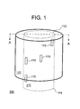
- FIG. 1 illustrates a mixing portion 100 of an injector.
- a center body 110 has an upper portion 112 and a lower portion 114 and is encircled by an outer body 120. Both the center body 110 and the outer body 120 are tube-like and are open at the upper portion 112 and the lower portion 114.
- the actuated areas 115 shown at FIG. 1 are exemplary indications of different areas of the center body 110 that may be moved by actuators.
- the actuators 320 (shown at FIG. 3 ) are not shown at FIG. 1 for clarity but may be, for example, wires attached to each of the actuated areas 115.
- the material of the center body 110 is a smart memory alloy (SMA) and each actuator 320 is an SMA actuator 320.
- the SMA actuators 320 may be wires carrying signals that cause movement at corresponding actuated areas 115.
- Each actuated area 115 of the center body 110 would be an area comprising a smart memory alloy that could be affected to move based on a control signal (from the actuator 320) in the form of a temperature change of the center body 110, for example.
- the shape of the center body 110 can be changed as needed to control an output from the center body 110 and, accordingly, the injector.
- actuation modes that may be used to shape the center body 110 include Micro-Electro-Mechanical Systems (MEMS), Micro-Optical-Electro-Mechanical Systems (MOMS/MOEMS), and Piezoelectric sensors and actuators (PZT).
- MEMS Micro-Electro-Mechanical Systems
- MOMS/MOEMS Micro-Optical-Electro-Mechanical Systems
- PZT Piezoelectric sensors and actuators
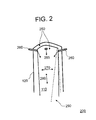
- FIG. 2 illustrates a cross-section 200 of the mixing portion 100 of an injector at A-A.
- Air 250 is supplied into both the center body 110 and the space between the center body 110 and the outer body 120.
- the air 250 between the center body 110 and the outer body 120 helps to reduce wear on the outer body 120 caused by the heat generated by the combustor.
- Fuel 265 is injected through inlets 260 that pass through the outer body 120 and into the center body 110 near the upper portion 112.
- the air 250 in the center body 110 and the fuel 265 mix in the center body 110 and the mixture is output at the lower portion 114 of the center body 110.
- the center body 110 may be subjected to horizontal flex 270 whereby the center body 110 is expanded from the inside out. In this case, there may be increased fuel 265 penetration into the mainstream (output from the lower portion 114 of the center body 110). Based on movement in the actuated areas 115, the center body 110 may instead experience elongation 280 whereby the center body 110 is tapered and lengthened as shown by 290. In this case, the direction of output of the fuel 265 and air 250 mixture at the lower portion 114 of the center body 110 may be controlled and, additionally, the mixing of fuel 265 with air 250 may be improved. Also, wear on the outer body 120 may be reduced when the center body 110 is elongated and tapered, because the gap between the center body 110 and outer body 120 is increased.
- FIG. 3 is a block diagram of a control system 300.
- the control system 300 includes a controller 310 and a plurality of actuators 320.
- FIG. 3 shows each of the actuators 320 being associated with a corresponding actuated area 115 (shown at FIG. 1 ).
- an actuator 320 may control movement of more than one actuated area 115.
- the control of the actuators 320 by the controller 310 may be based on a number of parameters. For example, flow rate, cooling rate, velocity profile, and exit pressure may be among the parameters considered by the controller 310 in controlling the actuators 320.
- the controller 310 may comprise one or more processors and one or more memory devices and may operate based on predetermined or user input rules for controlling output of the center body 110.
- the controller 310 may operate on the actuators 320 of a single injector (an LLI injector, for example) or may control actuators 320 of a number of injectors.
- the control may include radial expansion and contraction, tip expansion control, diaphragm control, pin actuated control, concentrically moving the cone, ball point tip control, and circumferential tapering volume control.
Landscapes
- Engineering & Computer Science (AREA)
- Chemical & Material Sciences (AREA)
- Combustion & Propulsion (AREA)
- Mechanical Engineering (AREA)
- General Engineering & Computer Science (AREA)
- Fuel-Injection Apparatus (AREA)
Abstract
An injection system includes a plurality of actuators (320). Each of the actuators (320) is configured to move one or more portions (115) of a center body of the fuel injector. The system also includes a controller (310) configured to control each of the plurality of actuators (320) individually to change a flow rate or a direction of output of a mixture of fuel and air from an output of the center body of the fuel injector.
Description
- The subject matter disclosed herein relates to the control of a fuel injector.
- In a fuel injection system, a fuel injector typically injects fuel at high pressure into a combustion engine where the fuel is mixed with air. In other injection systems, fuel and air are mixed and the mixture is injected. One example of such an injection system is late lean injection (LLI). The emissions of oxides of nitrogen, carbon monoxide, and unburned hydrocarbons in conventional gas turbine engines can be mitigated by the addition of an LLI system in a transition zone between the combustor and turbine. The LLI system can include a number of LLI injectors that inject a mixture of LLI fuel and LLI air into the transition zone.
- Increased control over injectors is needed. In the case of an LLI system, for example, increased control over LLI injectors would result in increased mitigation of the unwanted emissions from combustion engines.
- According to one aspect of the invention, a fuel injector control system includes a plurality of actuators, each actuator being configured to move one or more portions of a center body of the fuel injector; and a controller configured to control each of the plurality of actuators individually to change a flow rate or a direction of output of a mixture of fuel and air from an outlet of the center body of the fuel injector.
- According to another aspect of the invention, an adjustable fuel injector includes a center body having a tube-like shape with an opening at an upper portion and at a lower portion that is at an opposite end from the upper portion along a length of the center body, the center body configured to mix fuel and air, the fuel and the air being input at the upper portion, and to funnel a mixture of the fuel and the air through an outlet at the lower portion; an outer body having a tube-like shape, the outer body encircling the center body and air being input between the outer body and the center body at the upper portion; and a plurality of actuators controlled by a controller, each of the plurality of actuators being configured to move a different portion of the center body.
- According to yet another aspect of the invention, a method of controlling an output of an injector includes arranging a plurality of actuators to move different parts of a center body of the injector; and controlling movement of the plurality of actuators to change a size and a shape of an outlet of the center body of the injector.
- Referring now to the drawings wherein like elements are numbered alike in the several Figures:
-
FIG. 1 illustrates a mixing portion of an injector; -
FIG. 2 illustrates a cross-section of the mixing portion of an injector; and -
FIG. 3 is a block diagram of a control system according to an embodiment of the invention. -
FIG. 1 illustrates amixing portion 100 of an injector. As shown atFIG. 1 , acenter body 110 has anupper portion 112 and alower portion 114 and is encircled by anouter body 120. Both thecenter body 110 and theouter body 120 are tube-like and are open at theupper portion 112 and thelower portion 114. The actuatedareas 115 shown atFIG. 1 are exemplary indications of different areas of thecenter body 110 that may be moved by actuators. The actuators 320 (shown atFIG. 3 ) are not shown atFIG. 1 for clarity but may be, for example, wires attached to each of the actuatedareas 115. - In one embodiment, the material of the
center body 110 is a smart memory alloy (SMA) and eachactuator 320 is anSMA actuator 320. In that case, theSMA actuators 320 may be wires carrying signals that cause movement at corresponding actuatedareas 115. Each actuatedarea 115 of thecenter body 110 would be an area comprising a smart memory alloy that could be affected to move based on a control signal (from the actuator 320) in the form of a temperature change of thecenter body 110, for example. Based on a number and arrangement of the actuatedareas 115, the shape of thecenter body 110 can be changed as needed to control an output from thecenter body 110 and, accordingly, the injector. In alternate embodiments, actuation modes that may be used to shape thecenter body 110 include Micro-Electro-Mechanical Systems (MEMS), Micro-Optical-Electro-Mechanical Systems (MOMS/MOEMS), and Piezoelectric sensors and actuators (PZT). -
FIG. 2 illustrates across-section 200 of themixing portion 100 of an injector at A-A.Air 250 is supplied into both thecenter body 110 and the space between thecenter body 110 and theouter body 120. Theair 250 between thecenter body 110 and theouter body 120 helps to reduce wear on theouter body 120 caused by the heat generated by the combustor.Fuel 265 is injected throughinlets 260 that pass through theouter body 120 and into thecenter body 110 near theupper portion 112. Theair 250 in thecenter body 110 and thefuel 265 mix in thecenter body 110 and the mixture is output at thelower portion 114 of thecenter body 110. - By controlling the actuated
areas 115 such as the exemplary actuatedareas 115 shown atFIG. 1 , thecenter body 110 may be subjected tohorizontal flex 270 whereby thecenter body 110 is expanded from the inside out. In this case, there may be increasedfuel 265 penetration into the mainstream (output from thelower portion 114 of the center body 110). Based on movement in the actuatedareas 115, thecenter body 110 may instead experienceelongation 280 whereby thecenter body 110 is tapered and lengthened as shown by 290. In this case, the direction of output of thefuel 265 andair 250 mixture at thelower portion 114 of thecenter body 110 may be controlled and, additionally, the mixing offuel 265 withair 250 may be improved. Also, wear on theouter body 120 may be reduced when thecenter body 110 is elongated and tapered, because the gap between thecenter body 110 andouter body 120 is increased. -
FIG. 3 is a block diagram of acontrol system 300. Thecontrol system 300 includes acontroller 310 and a plurality ofactuators 320.FIG. 3 shows each of theactuators 320 being associated with a corresponding actuated area 115 (shown atFIG. 1 ). However, anactuator 320 may control movement of more than one actuatedarea 115. The control of theactuators 320 by thecontroller 310 may be based on a number of parameters. For example, flow rate, cooling rate, velocity profile, and exit pressure may be among the parameters considered by thecontroller 310 in controlling theactuators 320. Generally, thecontroller 310 may comprise one or more processors and one or more memory devices and may operate based on predetermined or user input rules for controlling output of thecenter body 110. Thecontroller 310 may operate on theactuators 320 of a single injector (an LLI injector, for example) or may controlactuators 320 of a number of injectors. In alternate embodiments, the control may include radial expansion and contraction, tip expansion control, diaphragm control, pin actuated control, concentrically moving the cone, ball point tip control, and circumferential tapering volume control. - It will be recognized that the various components and technologies may provide certain necessary or beneficial functionality or features. Accordingly, these functions and features as may be needed in support of the appended claims and variations therefore, are recognized as being inherently included as a part of the teachings herein and a part of the invention disclosed.
- While the invention has been described in detail in connection with only a limited number of embodiments, it should be readily understood that the invention is not limited to such disclosed embodiments. Rather, the invention can be modified to incorporate any number of variations, alterations, substitutions or equivalent arrangements not heretofore described, but which are commensurate with the spirit and scope of the invention. Additionally, while various embodiments of the invention have been described, it is to be understood that aspects of the invention may include only some of the described embodiments. Accordingly, the invention is not to be seen as limited by the foregoing description, but is only limited by the scope of the appended claims.
- Various aspects and embodiments of the present invention are defined by the following numbered clauses:
- 1. A fuel injector control system, comprising:
- a plurality of actuators, each actuator being configured to move one or more portions of a center body of the fuel injector; and
- a controller configured to control each of the plurality of actuators individually to change a flow rate or a direction of output of a mixture of fuel and air from an outlet of the center body of the fuel injector.
- 2. The system according to clause, wherein the plurality of actuators are comprised of smart memory alloys (SMA).
- 3. The system according to any preceding clause, wherein the plurality of actuators are comprised of Micro-Electro-Mechanical Systems (MEMS), Micro-Optical-Electro-Mechanical Systems (MOMS/MOEMS), or Piezoelectric sensors and actuators (PZT).
- 4. The system according to any preceding clause, wherein the controller controls at least one of the plurality of actuators to expand the center body and increase a flow of fuel into the fuel injector.
- 5. The system according to any preceding clause, wherein the controller controls at least one of the plurality of actuators to elongate the center body and increase a mixture of fuel and air in the fuel injector.
- 6. The system according to any preceding clause, wherein the controller controls each of the plurality of actuators based on a desired flow rate, cooling rate, velocity profile, or exit pressure.
Claims (14)
- An adjustable fuel injector, comprising:a center body (110) having a tube-like shape with an opening at an upper portion (112) and at a lower portion (114) that is at an opposite end from the upper portion (112) along a length of the center body (110), the center body (110) configured to mix fuel (265) and air (250), the fuel (265) and the air (250) being input at the upper portion (112), and to funnel a mixture of the fuel (265) and the air (250) through an outlet at the lower portion (114);an outer body (120) having a tube-like shape, the outer body (120) encircling the center body (110) and air being input between the outer body (120) and the center body (110) at the upper portion (112); anda plurality of actuators (320) controlled by a controller (310), each of the plurality of actuators (320) being configured to move a different portion of the center body (110).
- The fuel injector according to claim 1, wherein the fuel (265) is injected substantially tangential to a length of the center body (110) into the center body (110) at the upper portion (112) through a plurality of openings in the tube-like shape of the center body (110) at the upper portion (112).
- The fuel injector according to claim 1 or 2, wherein at least one of the plurality of actuators (320) is controlled to change a shape of the outlet of the center body (110) and thereby change a direction of the mixture of the fuel (265) and the air (250) through the outlet.
- The fuel injector according to any of claims 1 to 3, wherein at least one of the plurality of actuators (320) is controlled to change a flow rate of the mixture of the fuel (265) and the air (250) through the outlet by changing a slope of the center body (110) from the upper portion (112) to the lower portion (114).
- The fuel injector according to any of claims 1 to 4, wherein the plurality of actuators are comprised of smart memory alloys (SMA).
- The fuel injector according to any preceding claim, wherein the plurality of actuators are comprised of Micro-Electro-Mechanical Systems (MEMS), Micro-Optical-Electro-Mechanical Systems (MOMS/MOEMS), or Piezoelectric sensors and actuators (PZT).
- The fuel injector according to any preceding claim, wherein at least one of the plurality of actuators (320) is controlled to expand the center body (110) out toward the outer body (120).
- The fuel injector according to any preceding claim, wherein at least one of the plurality of actuators (320) is controlled to elongate the center body (110) and taper the outlet of the center body (110) at the lower portion (114).
- A fuel injector control system (300), comprising:the adjustable fuel injector of any of claims 1 to 8; anda controller (310) configured to control each of the plurality of actuators (320) individually to change a flow rate or a direction of output of a mixture of fuel (265) and air (50) from an outlet of the center body (110) of the fuel injector.
- The system according to claim 9, wherein the controller (310) controls each of the plurality of actuators (320) based on a desired flow rate, cooling rate, velocity profile, or exit pressure.
- A method of controlling an injector, the method comprising:arranging a plurality of actuators (320) to move different parts of a center body (110) of the injector; andcontrolling movement of the plurality of actuators (320) to change a size and a shape of an outlet of the center body (110) of the injector.
- The method according to claim 11, wherein the controlling includes controlling one or more of the plurality of actuators (320) to expand the center body (110) of the injector and to increase a flow rate of material from the outlet of the center body (110) of the injector.
- The method according to claim 11 or 12, wherein the controlling includes controlling one or more of the plurality of actuators (320) to elongate the center body of the injector and to taper the outlet of the center body of the injector.
- The method according to any of claims 11 to 13, wherein the controlling is based on a desired flow rate, cooling rate, velocity profile, or exit pressure.
Applications Claiming Priority (1)
| Application Number | Priority Date | Filing Date | Title |
|---|---|---|---|
| US13/453,276 US20130277447A1 (en) | 2012-04-23 | 2012-04-23 | Method and system to control a fuel injector |
Publications (1)
| Publication Number | Publication Date |
|---|---|
| EP2657600A2 true EP2657600A2 (en) | 2013-10-30 |
Family
ID=48139789
Family Applications (1)
| Application Number | Title | Priority Date | Filing Date |
|---|---|---|---|
| EP13164015.3A Withdrawn EP2657600A2 (en) | 2012-04-23 | 2013-04-16 | Method and system to control a fuel injector |
Country Status (5)
| Country | Link |
|---|---|
| US (1) | US20130277447A1 (en) |
| EP (1) | EP2657600A2 (en) |
| JP (1) | JP2013224656A (en) |
| CN (1) | CN103375273A (en) |
| RU (1) | RU2013118437A (en) |
Family Cites Families (8)
| Publication number | Priority date | Publication date | Assignee | Title |
|---|---|---|---|---|
| US6318641B1 (en) * | 2000-02-11 | 2001-11-20 | Delphi Technologies, Inc. | Shape memory alloy fuel injector small package integral design |
| US6691977B2 (en) * | 2001-03-16 | 2004-02-17 | Delphi Technologies, Inc. | Shape memory alloy fuel injector |
| US20070235554A1 (en) * | 2006-03-29 | 2007-10-11 | Williams Arthur R | Dual stroke injector using SMA |
| US8635985B2 (en) * | 2008-01-07 | 2014-01-28 | Mcalister Technologies, Llc | Integrated fuel injectors and igniters and associated methods of use and manufacture |
| US7896257B2 (en) * | 2008-02-16 | 2011-03-01 | Mi Yan | Fuel injector with real-time feedback control |
| US8683808B2 (en) * | 2009-01-07 | 2014-04-01 | General Electric Company | Late lean injection control strategy |
| US8186165B2 (en) * | 2009-03-16 | 2012-05-29 | General Electric Company | Turbine fuel nozzle having heat control |
| FR2945075B1 (en) * | 2009-04-29 | 2015-06-05 | Snecma | METHOD AND DEVICE FOR FEEDING A TURBOMACHINE CHAMBER WITH A REGULATED FUEL FLOW |
-
2012
- 2012-04-23 US US13/453,276 patent/US20130277447A1/en not_active Abandoned
-
2013
- 2013-04-16 EP EP13164015.3A patent/EP2657600A2/en not_active Withdrawn
- 2013-04-17 JP JP2013086177A patent/JP2013224656A/en active Pending
- 2013-04-22 RU RU2013118437/06A patent/RU2013118437A/en not_active Application Discontinuation
- 2013-04-23 CN CN2013101429363A patent/CN103375273A/en active Pending
Also Published As
| Publication number | Publication date |
|---|---|
| US20130277447A1 (en) | 2013-10-24 |
| RU2013118437A (en) | 2014-10-27 |
| JP2013224656A (en) | 2013-10-31 |
| CN103375273A (en) | 2013-10-30 |
Similar Documents
| Publication | Publication Date | Title |
|---|---|---|
| KR102145175B1 (en) | Flamesheet cumbustor dome | |
| US9291350B2 (en) | System for providing a working fluid to a combustor | |
| EP2657605A2 (en) | System and Method for Supplying a Working Fluid to a Combustor | |
| EP2400216A1 (en) | Lance of a reheat burner | |
| US20140338337A1 (en) | Injectors for multipoint injection | |
| JP7623338B2 (en) | Fluid mixing method and system | |
| US20190309952A1 (en) | Fuel oil axial stage combustion for improved turbine combustor performance | |
| EP2071178A1 (en) | Injection nozzle | |
| EP2657600A2 (en) | Method and system to control a fuel injector | |
| KR102050563B1 (en) | Combustor and gas turbine comprising the same | |
| CN109790981A (en) | Use the technology of the operating point of pilot air control combustion system | |
| EP2789916B1 (en) | Combustion chamber | |
| JP5054988B2 (en) | Combustor | |
| KR20180072348A (en) | Turbines including flue gas recirculation combustors. | |
| EP3396145B1 (en) | Jet engine and flying object | |
| KR101904653B1 (en) | Fuel injection apparatus for dual-mode ramjet engine | |
| JP2017536524A (en) | A liner with a predetermined contour of a flame sheet combustor | |
| CN110030579B (en) | Second stage combustor for a sequential combustor of a gas turbine | |
| EP2116769A1 (en) | Fuel lance for a burner | |
| KR101531161B1 (en) | Gas turbine having fuel nozzel array | |
| EP2853719A1 (en) | Gas turbine with staged fuel injection | |
| US10371384B2 (en) | Fuel injection system for aircraft turbomachine, comprising a variable section air through duct | |
| KR20190133649A (en) | Combustor and gas turbine comprising the same | |
| JP5533173B2 (en) | Fuel supply device | |
| RU93497U1 (en) | GAS-BURNER |
Legal Events
| Date | Code | Title | Description |
|---|---|---|---|
| PUAI | Public reference made under article 153(3) epc to a published international application that has entered the european phase |
Free format text: ORIGINAL CODE: 0009012 |
|
| AK | Designated contracting states |
Kind code of ref document: A2 Designated state(s): AL AT BE BG CH CY CZ DE DK EE ES FI FR GB GR HR HU IE IS IT LI LT LU LV MC MK MT NL NO PL PT RO RS SE SI SK SM TR |
|
| AX | Request for extension of the european patent |
Extension state: BA ME |
|
| STAA | Information on the status of an ep patent application or granted ep patent |
Free format text: STATUS: THE APPLICATION IS DEEMED TO BE WITHDRAWN |
|
| 18D | Application deemed to be withdrawn |
Effective date: 20161101 |