EP2657489A2 - Method for controlling auto idle state of heavy construction equipment - Google Patents
Method for controlling auto idle state of heavy construction equipment Download PDFInfo
- Publication number
- EP2657489A2 EP2657489A2 EP11851907.3A EP11851907A EP2657489A2 EP 2657489 A2 EP2657489 A2 EP 2657489A2 EP 11851907 A EP11851907 A EP 11851907A EP 2657489 A2 EP2657489 A2 EP 2657489A2
- Authority
- EP
- European Patent Office
- Prior art keywords
- engine rpm
- auto idle
- engine
- rpm
- construction equipment
- Prior art date
- Legal status (The legal status is an assumption and is not a legal conclusion. Google has not performed a legal analysis and makes no representation as to the accuracy of the status listed.)
- Granted
Links
Images

Classifications
-
- F—MECHANICAL ENGINEERING; LIGHTING; HEATING; WEAPONS; BLASTING
- F02—COMBUSTION ENGINES; HOT-GAS OR COMBUSTION-PRODUCT ENGINE PLANTS
- F02D—CONTROLLING COMBUSTION ENGINES
- F02D29/00—Controlling engines, such controlling being peculiar to the devices driven thereby, the devices being other than parts or accessories essential to engine operation, e.g. controlling of engines by signals external thereto
- F02D29/02—Controlling engines, such controlling being peculiar to the devices driven thereby, the devices being other than parts or accessories essential to engine operation, e.g. controlling of engines by signals external thereto peculiar to engines driving vehicles; peculiar to engines driving variable pitch propellers
-
- E—FIXED CONSTRUCTIONS
- E02—HYDRAULIC ENGINEERING; FOUNDATIONS; SOIL SHIFTING
- E02F—DREDGING; SOIL-SHIFTING
- E02F9/00—Component parts of dredgers or soil-shifting machines, not restricted to one of the kinds covered by groups E02F3/00 - E02F7/00
- E02F9/20—Drives; Control devices
- E02F9/2025—Particular purposes of control systems not otherwise provided for
-
- F—MECHANICAL ENGINEERING; LIGHTING; HEATING; WEAPONS; BLASTING
- F02—COMBUSTION ENGINES; HOT-GAS OR COMBUSTION-PRODUCT ENGINE PLANTS
- F02D—CONTROLLING COMBUSTION ENGINES
- F02D41/00—Electrical control of supply of combustible mixture or its constituents
- F02D41/02—Circuit arrangements for generating control signals
- F02D41/04—Introducing corrections for particular operating conditions
-
- F—MECHANICAL ENGINEERING; LIGHTING; HEATING; WEAPONS; BLASTING
- F02—COMBUSTION ENGINES; HOT-GAS OR COMBUSTION-PRODUCT ENGINE PLANTS
- F02D—CONTROLLING COMBUSTION ENGINES
- F02D41/00—Electrical control of supply of combustible mixture or its constituents
- F02D41/02—Circuit arrangements for generating control signals
- F02D41/04—Introducing corrections for particular operating conditions
- F02D41/08—Introducing corrections for particular operating conditions for idling
-
- F—MECHANICAL ENGINEERING; LIGHTING; HEATING; WEAPONS; BLASTING
- F02—COMBUSTION ENGINES; HOT-GAS OR COMBUSTION-PRODUCT ENGINE PLANTS
- F02D—CONTROLLING COMBUSTION ENGINES
- F02D2200/00—Input parameters for engine control
- F02D2200/50—Input parameters for engine control said parameters being related to the vehicle or its components
- F02D2200/501—Vehicle speed
Definitions
- An exemplary embodiment of the present invention relates to heavy construction equipment, and more particularly, to a method for controlling an auto idle state of heavy construction equipment that can enhance convenience for a worker, and increase workability and productivity by allowing an auto idle engine RPM of an engine RPM, which is decreased when a work stoppage is continued for a predetermined time, to be variable according to a work situation.
- heavy construction equipment including an excavator performs various types of work at a worker-set engine RPM (for example, 1,800 to 2,500 RPM) within a predetermined range after starting an engine thereof.
- the worker-set engine RPM is automatically switched to an auto idle engine RPM (for example, 1,200 RPM) at a lower level than the set engine RPM set by the worker after a predetermined elapses and when a predetermined time additionally elapses in this state, the auto idle engine RPM is automatically switched to a low idle engine RPM (for example, 800 RPM) at a lower level than the auto idle engine RPM, thereby improving fuel efficiency.
- an auto idle engine RPM for example, 1,200 RPM
- a low idle engine RPM for example, 800 RPM
- the auto idle engine RPM In order for the worker to perform the work again in a state of the auto idle engine RPM in which the work temporarily stops, the auto idle engine RPM needs to be increased to the worker-set engine RPM (for example, 2,000 RPM).
- An exemplary embodiment of the present invention is contrived in consideration of the aforementioned problems, and an object of an exemplary embodiment of the present invention is to provide a method for controlling an auto idle state of heavy construction equipment that can rapidly switch an auto idle engine RPM to a worker-set engine RPM to improve worker convenience and productivity and expect improvement of fuel efficiency.
- a method for controlling an auto idle state of heavy construction equipment of an exemplary embodiment of the present invention is characterized in that an auto idle engine RPM value is changed depending on an average work engine RPM value per predetermined time of a worker.
- the method for controlling an auto idle state of heavy construction equipment of an exemplary embodiment of the present invention includes: storing, by a vehicle controller (VCU) that receives engine actuation information from an engine controller (ECU), an average traveling value of a worker-set engine RPM for a first set time when the heavy construction equipment is actuated at the worker-set engine RPM; and calculating a variable auto idle engine RPM changed depending on the average traveling value of the worker-set engine RPM for the first set time and actuating an engine at the variable auto idle engine RPM when work is stopped for a previously set predetermined time.
- VCU vehicle controller
- ECU engine controller
- the method for controlling an auto idle state of heavy construction equipment may further includes actuating the engine at a previously set auto idle engine RPM when the work of the heavy construction equipment is further stopped for a previously set second set time after being switched to the variable auto idle engine RPM.
- variable auto idle engine RPM may be calculated to be lower than the set auto idle engine RPM
- variable auto idle engine RPM is changed to the set auto idle engine RPM
- the calculating of the average traveling value of the set engine RPM may be performed based on only fluctuations of a set engine RPM set by an operator for the first set time.
- the calculating of the average traveling value of the set engine RPM may be performed by providing the variable auto idle engine RPM used for the first set time.
- a method for controlling an auto idle state of heavy construction equipment of an exemplary embodiment of the present invention since a variable auto idle engine RPM is changed due to a work feature of a worker of the heavy construction equipment, an engine load becomes small while a worker-set engine RPM is switched to the variable auto idle engine RPM, and a return reaction time from the variable auto idle engine RPM to the worker-set engine RPM becomes short when work is performed again, thereby enhancing worker convenience and increasing working efficiency, and the worker-set engine RPM is switched to the variable auto idle engine RPM, which is switched again to a set idle engine RPM at a lower level than the variable auto idle engine RPM, thereby preventing degradation of fuel efficiency.
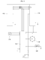
- FIG. 1 illustrates a control circuit diagram of an engine RPM of heavy construction equipment according to an exemplary embodiment of the present invention.
- an engine RPM control circuit of the heaving construction equipment is configured in such a manner that an auto idle input device 110 and a key switch (start switch) 120 of a driver seat , which enable setting an auto idle engine RPM, are connected to an engine controller (ECU) 130 controlling an engine RPM, and an auto idle pressure switch 140 and an engine control dial 150 of a driver's seat are connected to the engine controller 130 through a vehicle controller (VCU) 160.
- ECU engine controller
- VCU vehicle controller
- the vehicle controller 160 transmits an RPM switching signal to the engine controller 130, and the engine controller 130, which receives the RPM switching signal from the vehicle controller 160, automatically switches a set engine RPM set by a worker to an auto idle engine RPM (for example, 1,200 RPM), automatically switches the auto idle engine RPM to a low idle engine RPM (for example, 800 RPM), or automatically switches the auto idle engine RPM or the low idle engine RPM to the set engine RPM.
- an auto idle engine RPM for example, 1,200 RPM
- a low idle engine RPM for example, 800 RPM
- the auto idle engine RPM is used by being again divided into a set auto idle engine RPM which is previously set and a variable auto idle engine RPM which varies depending on a working situation.
- the set auto idle engine RPM may be a value which an equipment manufacturer sets at the time of manufacturing the heavy construction equipment and a value which an operator sets while operating the equipment.
- the set auto idle engine RPM the low idle engine RPM described in the related art may be used.
- an engine may be driven sequentially at the set engine RPM, the variable auto idle engine RPM, the set auto idle engine RPM, and the low idle engine RPM.
- the vehicle controller 160 controls the engine controller 130 so that the engine is driven at the set engine RPM set by the operator.
- the aforementioned set engine RPM may be changed by selection by the operator, for example, manipulation of the engine control dial 150 while working.
- the vehicle controller 160 continuously monitors fluctuations of the set engine RPM set by the worker while controlling the engine to be driven at the changed set engine RPM by reflecting the changed set engine RPM whenever the set engine RPM is changed. That is, an average traveling value of the set engine RPM is calculated and stored for a first time previously set based on the present point, and an average traveling value of the set engine RPM changed as time elapses is updated.
- the set engine average traveling value may be calculated considering that the engine is driven at the variable auto idle engine RPM, the set auto idle engine RPM, and the like, which will be described below, as the equipment stops working.
- the variable auto idle engine RPM is calculated to be low, thereby achieving a fuel efficiency effect, and when such a situation is not considered, the variable auto idle engine RPM rapidly returns to the set auto idle engine RPM, thereby improving workability and productivity. Therefore, whether the variable auto idle engine RPM, the set auto idle engine RPM, and the low idle engine RPM are reflected on the set engine RPM average traveling value may be appropriately considered in response to a driver's tendency, a workplace situation, and the like.
- a selection switch (not illustrated) may be further provided so as for the operator to select a method for calculating the set engine RPM average traveling value.
- the vehicle controller 160 calculates the variable auto idle engine RPM by using the previously calculated set engine RPM average traveling value.
- the variable auto idle engine RPM is set to be 80% of the average RPM traveling value. For example, when the average of an RPM which the operator uses for the first time is 2,000 RPM, the variable auto idle engine RPM is set to 1,600 RPM.
- the engine monitors whether the work of the heavy construction equipment maintains a stopped state for a second set time again.
- the second set time may be set by considering an average working pattern of workers of the heavy construction equipment and may be set to, for example, 30 seconds.
- the engine RPM is increased again to the set engine RPM, and when the work of the heavy construction equipment maintains the stopped state for the second set time, the engine RPM is controlled by the set auto idle engine RPM.
- the set auto idle engine RPM is set to be lower than the variable auto idle engine RPM. For example, the set auto idle engine RPM may be set to 1,200 RPM.
- variable auto idle engine RPM is fixed to the set auto idle engine RPM, and when the variable auto idle engine RPM is recalculated afterwards, the recalculated variable auto idle engine RPM may be reflected.
- the reason is that the auto idle engine RPM is set in consideration of both workability and fuel efficiency.
- the engine when the work of the equipment is started, the engine may be controlled to be driven at the set engine RPM set by the operator.
- the set auto idle engine RPM may be set to a general low idle engine RPM in order to maximize a fuel efficiency effect.
- the engine is driven at the set engine RPM and thereafter, the engine is driven at the variable auto idle engine RPM instead of a set auto idle engine RPM fixed while working is not performed. Accordingly, when the variable auto idle engine RPM returns to the set engine RPM by the start of the work, a load and an impact, which are small, act on the engine and return reaction time also becomes short, thereby enhancing worker convenience and increasing working efficiency.
- An exemplary embodiment of the present invention can be used in a method for controlling an auto idle state of heavy construction equipment that can rapidly switch an auto idle engine RPM to a worker-set engine RPM to enhance worker convenience and improve workability and productivity.
Landscapes
- Engineering & Computer Science (AREA)
- General Engineering & Computer Science (AREA)
- Chemical & Material Sciences (AREA)
- Combustion & Propulsion (AREA)
- Mechanical Engineering (AREA)
- Mining & Mineral Resources (AREA)
- Civil Engineering (AREA)
- Structural Engineering (AREA)
- Control Of Vehicle Engines Or Engines For Specific Uses (AREA)
- Operation Control Of Excavators (AREA)
- Combined Controls Of Internal Combustion Engines (AREA)
Abstract
Description
- An exemplary embodiment of the present invention relates to heavy construction equipment, and more particularly, to a method for controlling an auto idle state of heavy construction equipment that can enhance convenience for a worker, and increase workability and productivity by allowing an auto idle engine RPM of an engine RPM, which is decreased when a work stoppage is continued for a predetermined time, to be variable according to a work situation.
- In general, heavy construction equipment including an excavator performs various types of work at a worker-set engine RPM (for example, 1,800 to 2,500 RPM) within a predetermined range after starting an engine thereof. In addition, when a worker stops the work, the worker-set engine RPM is automatically switched to an auto idle engine RPM (for example, 1,200 RPM) at a lower level than the set engine RPM set by the worker after a predetermined elapses and when a predetermined time additionally elapses in this state, the auto idle engine RPM is automatically switched to a low idle engine RPM (for example, 800 RPM) at a lower level than the auto idle engine RPM, thereby improving fuel efficiency.
- In order for the worker to perform the work again in a state of the auto idle engine RPM in which the work temporarily stops, the auto idle engine RPM needs to be increased to the worker-set engine RPM (for example, 2,000 RPM).
- However, in the related art, since the auto idle engine RPM is fixed to a specific RPM, when a difference between the set engine RPM and the auto idle RPM is large, it takes a lot of time to reach the set engine RPM from the auto idle engine RPM, and as a result, the work is slowly performed, thereby degrading workability and productivity of the heavy construction equipment.
- An exemplary embodiment of the present invention is contrived in consideration of the aforementioned problems, and an object of an exemplary embodiment of the present invention is to provide a method for controlling an auto idle state of heavy construction equipment that can rapidly switch an auto idle engine RPM to a worker-set engine RPM to improve worker convenience and productivity and expect improvement of fuel efficiency.
- A method for controlling an auto idle state of heavy construction equipment of an exemplary embodiment of the present invention is characterized in that an auto idle engine RPM value is changed depending on an average work engine RPM value per predetermined time of a worker.
- That is, the method for controlling an auto idle state of heavy construction equipment of an exemplary embodiment of the present invention includes: storing, by a vehicle controller (VCU) that receives engine actuation information from an engine controller (ECU), an average traveling value of a worker-set engine RPM for a first set time when the heavy construction equipment is actuated at the worker-set engine RPM; and calculating a variable auto idle engine RPM changed depending on the average traveling value of the worker-set engine RPM for the first set time and actuating an engine at the variable auto idle engine RPM when work is stopped for a previously set predetermined time.
- Moreover, the method for controlling an auto idle state of heavy construction equipment may further includes actuating the engine at a previously set auto idle engine RPM when the work of the heavy construction equipment is further stopped for a previously set second set time after being switched to the variable auto idle engine RPM.
- Further, when the variable auto idle engine RPM may be calculated to be lower than the set auto idle engine RPM, the variable auto idle engine RPM is changed to the set auto idle engine RPM.
- In addition, the calculating of the average traveling value of the set engine RPM may be performed based on only fluctuations of a set engine RPM set by an operator for the first set time.
- Further, the calculating of the average traveling value of the set engine RPM may be performed by providing the variable auto idle engine RPM used for the first set time.
- According to a method for controlling an auto idle state of heavy construction equipment of an exemplary embodiment of the present invention, since a variable auto idle engine RPM is changed due to a work feature of a worker of the heavy construction equipment, an engine load becomes small while a worker-set engine RPM is switched to the variable auto idle engine RPM, and a return reaction time from the variable auto idle engine RPM to the worker-set engine RPM becomes short when work is performed again, thereby enhancing worker convenience and increasing working efficiency, and the worker-set engine RPM is switched to the variable auto idle engine RPM, which is switched again to a set idle engine RPM at a lower level than the variable auto idle engine RPM, thereby preventing degradation of fuel efficiency.
-
-
FIG. 1 is a control circuit diagram of an engine RPM of heavy construction equipment according to an exemplary embodiment of the present invention. -
FIG. 2 is a control flowchart illustrating a method for controlling an auto idle state of heavy construction equipment according to an exemplary embodiment of the present invention. -
- 110: Auto idle input device
- 120: Key switch
- 130: Engine controller
- 140: Auto idle pressure switch
- 150: Engine control dial
- 160: Vehicle controller
- Detailed technological contents of an exemplary embodiment of the present invention for achieving the object will be described below in detail with reference to the accompanying drawings.
-
FIG. 1 illustrates a control circuit diagram of an engine RPM of heavy construction equipment according to an exemplary embodiment of the present invention. - As illustrated in
FIG. 1 , an engine RPM control circuit of the heaving construction equipment is configured in such a manner that an autoidle input device 110 and a key switch (start switch) 120 of a driver seat , which enable setting an auto idle engine RPM, are connected to an engine controller (ECU) 130 controlling an engine RPM, and an autoidle pressure switch 140 and anengine control dial 150 of a driver's seat are connected to theengine controller 130 through a vehicle controller (VCU) 160. - In the engine RPM control circuit of the heavy construction equipment, the
vehicle controller 160 transmits an RPM switching signal to theengine controller 130, and theengine controller 130, which receives the RPM switching signal from thevehicle controller 160, automatically switches a set engine RPM set by a worker to an auto idle engine RPM (for example, 1,200 RPM), automatically switches the auto idle engine RPM to a low idle engine RPM (for example, 800 RPM), or automatically switches the auto idle engine RPM or the low idle engine RPM to the set engine RPM. - Herein, the auto idle engine RPM is used by being again divided into a set auto idle engine RPM which is previously set and a variable auto idle engine RPM which varies depending on a working situation. The set auto idle engine RPM may be a value which an equipment manufacturer sets at the time of manufacturing the heavy construction equipment and a value which an operator sets while operating the equipment. Meanwhile, according to another exemplary embodiment of the present invention, as the set auto idle engine RPM, the low idle engine RPM described in the related art may be used. Further, according to another exemplary embodiment of the present invention, an engine may be driven sequentially at the set engine RPM, the variable auto idle engine RPM, the set auto idle engine RPM, and the low idle engine RPM.
- Hereinafter, an engine control according to an exemplary embodiment of the present invention will be described with reference to
FIG. 2 . - The
vehicle controller 160 controls theengine controller 130 so that the engine is driven at the set engine RPM set by the operator. The aforementioned set engine RPM may be changed by selection by the operator, for example, manipulation of theengine control dial 150 while working. Thevehicle controller 160 continuously monitors fluctuations of the set engine RPM set by the worker while controlling the engine to be driven at the changed set engine RPM by reflecting the changed set engine RPM whenever the set engine RPM is changed. That is, an average traveling value of the set engine RPM is calculated and stored for a first time previously set based on the present point, and an average traveling value of the set engine RPM changed as time elapses is updated. The set engine average traveling value may be calculated considering that the engine is driven at the variable auto idle engine RPM, the set auto idle engine RPM, and the like, which will be described below, as the equipment stops working. When such a situation is considered, the variable auto idle engine RPM is calculated to be low, thereby achieving a fuel efficiency effect, and when such a situation is not considered, the variable auto idle engine RPM rapidly returns to the set auto idle engine RPM, thereby improving workability and productivity. Therefore, whether the variable auto idle engine RPM, the set auto idle engine RPM, and the low idle engine RPM are reflected on the set engine RPM average traveling value may be appropriately considered in response to a driver's tendency, a workplace situation, and the like. To this end, a selection switch (not illustrated) may be further provided so as for the operator to select a method for calculating the set engine RPM average traveling value. - Meanwhile, when the work of the heavy construction equipment stops for a predetermined time or more under the aforementioned control, the
vehicle controller 160 calculates the variable auto idle engine RPM by using the previously calculated set engine RPM average traveling value. According to the exemplary embodiment, the variable auto idle engine RPM is set to be 80% of the average RPM traveling value. For example, when the average of an RPM which the operator uses for the first time is 2,000 RPM, the variable auto idle engine RPM is set to 1,600 RPM. - As such, when the engine starts to be driven at the variable auto idle engine RPM, the engine monitors whether the work of the heavy construction equipment maintains a stopped state for a second set time again. The second set time may be set by considering an average working pattern of workers of the heavy construction equipment and may be set to, for example, 30 seconds. When the work progresses again, the engine RPM is increased again to the set engine RPM, and when the work of the heavy construction equipment maintains the stopped state for the second set time, the engine RPM is controlled by the set auto idle engine RPM. The set auto idle engine RPM is set to be lower than the variable auto idle engine RPM. For example, the set auto idle engine RPM may be set to 1,200 RPM. If the set engine RPM average traveling value is calculated to be lower than the set auto idle engine RPM, the variable auto idle engine RPM is fixed to the set auto idle engine RPM, and when the variable auto idle engine RPM is recalculated afterwards, the recalculated variable auto idle engine RPM may be reflected. In general, the reason is that the auto idle engine RPM is set in consideration of both workability and fuel efficiency. When the equipment maintains the stopped state for a third time, which is previously set, while the engine is driven at the set auto idle engine RPM, fuel consumption may be minimized by stopping the engine or controlling the engine at the aforementioned low idle engine RPM. Of course, even in this case, when the work of the equipment is started, the engine may be controlled to be driven at the set engine RPM set by the operator. Moreover, the set auto idle engine RPM may be set to a general low idle engine RPM in order to maximize a fuel efficiency effect.
- As described above, the engine is driven at the set engine RPM and thereafter, the engine is driven at the variable auto idle engine RPM instead of a set auto idle engine RPM fixed while working is not performed. Accordingly, when the variable auto idle engine RPM returns to the set engine RPM by the start of the work, a load and an impact, which are small, act on the engine and return reaction time also becomes short, thereby enhancing worker convenience and increasing working efficiency.
- An exemplary embodiment of the present invention described as above is not limited to the foregoing description, and it will be apparent to those skilled in the art that various substitutions, transformations, and changes can be made within the scope without departing from the technical spirit of the preset invention.
- An exemplary embodiment of the present invention can be used in a method for controlling an auto idle state of heavy construction equipment that can rapidly switch an auto idle engine RPM to a worker-set engine RPM to enhance worker convenience and improve workability and productivity.
Claims (5)
- A method for controlling an auto idle state of heavy construction equipment, comprising:storing, by a vehicle controller (VCU) that receives engine actuation information from an engine controller (ECU), an average traveling value of a worker-set engine RPM for a first set time when the heavy construction equipment is actuated at the worker-set engine RPM; andcalculating a variable auto idle engine RPM changed depending on the average traveling value of the worker-set engine RPM for the first set time and actuating an engine at the variable auto idle engine RPM when work is stopped for a previously set predetermined time.
- The method for controlling an auto idle state of heavy construction equipment of claim 1, further comprising:actuating the engine at a previously set auto idle engine RPM when the work of the heavy construction equipment is further stopped for a previously set second set time after being switched to the variable auto idle engine RPM.
- The method for controlling an auto idle state of heavy construction equipment of claim 2, wherein when the variable auto idle engine RPM is calculated to be lower than the set auto idle engine RPM, the variable auto idle engine RPM is changed to the set auto idle engine RPM.
- The method for controlling an auto idle state of heavy construction equipment of claim 1, wherein the calculating of the average traveling value of the set engine RPM is performed based on only fluctuations of a set engine RPM set by an operator for the first set time.
- The method for controlling an auto idle state of heavy construction equipment of claim 1, wherein the calculating of the average traveling value of the set engine RPM is performed by providing the variable auto idle engine RPM used for the first set time.
Applications Claiming Priority (2)
| Application Number | Priority Date | Filing Date | Title |
|---|---|---|---|
| KR1020100131127A KR101687418B1 (en) | 2010-12-21 | 2010-12-21 | an auto-idle control method for a construction heavy equipment |
| PCT/KR2011/009906 WO2012087011A2 (en) | 2010-12-21 | 2011-12-21 | Method for controlling auto idle state of heavy construction equipment |
Publications (3)
| Publication Number | Publication Date |
|---|---|
| EP2657489A2 true EP2657489A2 (en) | 2013-10-30 |
| EP2657489A4 EP2657489A4 (en) | 2017-08-23 |
| EP2657489B1 EP2657489B1 (en) | 2018-08-29 |
Family
ID=46314618
Family Applications (1)
| Application Number | Title | Priority Date | Filing Date |
|---|---|---|---|
| EP11851907.3A Active EP2657489B1 (en) | 2010-12-21 | 2011-12-21 | Method for controlling auto idle state of heavy construction equipment |
Country Status (5)
| Country | Link |
|---|---|
| US (1) | US8874328B2 (en) |
| EP (1) | EP2657489B1 (en) |
| KR (1) | KR101687418B1 (en) |
| CN (1) | CN103270277B (en) |
| WO (1) | WO2012087011A2 (en) |
Families Citing this family (7)
| Publication number | Priority date | Publication date | Assignee | Title |
|---|---|---|---|---|
| KR102040331B1 (en) * | 2012-12-26 | 2019-11-04 | 두산인프라코어 주식회사 | Apparatus and method for controlling auto idle of construction equipment |
| CN105121750B (en) * | 2013-04-04 | 2017-06-27 | 斗山英维高株式会社 | The control device and control method of engineering machinery engine |
| US9759147B2 (en) * | 2014-08-29 | 2017-09-12 | Cnh Industrial America Llc | Idle return system and method for an off highway vehicle |
| CN107110035B (en) * | 2014-10-06 | 2020-07-10 | 日立建机株式会社 | work machinery |
| CN105649794B (en) * | 2015-12-31 | 2018-10-16 | 中联重科股份有限公司渭南分公司 | Engine automatic idle speed control device, method, system and construction machinery |
| US10037634B2 (en) * | 2016-03-22 | 2018-07-31 | Deere & Company | System and method for idle state determination |
| US12540585B2 (en) * | 2024-01-26 | 2026-02-03 | Ford Global Technologies, Llc | System and method for power take-off control |
Family Cites Families (13)
| Publication number | Priority date | Publication date | Assignee | Title |
|---|---|---|---|---|
| KR0126450B1 (en) | 1993-09-20 | 1997-12-26 | 황병주 | Engine and pump power control system and method of an excavator |
| JPH0974876A (en) * | 1995-09-07 | 1997-03-25 | Kubota Corp | Vehicle speed control device for reaper |
| JP3660501B2 (en) | 1998-05-28 | 2005-06-15 | 日立建機株式会社 | Engine speed control device for construction machinery |
| JP2000248975A (en) * | 1999-03-01 | 2000-09-12 | Komatsu Ltd | Engine speed control device for work vehicle |
| JP3610872B2 (en) * | 2000-04-12 | 2005-01-19 | 日産自動車株式会社 | Idle rotation speed control device for hybrid vehicle |
| KR100702178B1 (en) * | 2005-03-02 | 2007-04-02 | 볼보 컨스트럭션 이키프먼트 홀딩 스웨덴 에이비 | Engine speed control device and control method of construction equipment |
| JP2007023862A (en) * | 2005-07-14 | 2007-02-01 | Yamaha Motor Co Ltd | Internal combustion engine and rotational speed control method for internal combustion engine |
| JP5134238B2 (en) * | 2006-12-15 | 2013-01-30 | 株式会社小松製作所 | Engine load control device for work vehicle |
| CN100447390C (en) * | 2007-02-12 | 2008-12-31 | 三一重机有限公司 | A method for automatic idle speed control of an excavator engine |
| CN100460649C (en) * | 2007-02-13 | 2009-02-11 | 三一重机有限公司 | A method for controlling the engine speed of an excavator |
| EP2072785B1 (en) * | 2007-12-21 | 2011-02-23 | Caterpillar Inc. | Controlling engine speed within a machine |
| KR101549253B1 (en) * | 2008-12-24 | 2015-09-01 | 두산인프라코어 주식회사 | Apparatus and method for controlling engine speed in the idle state of a construction equipment |
| US10183547B2 (en) * | 2012-05-24 | 2019-01-22 | Honda Motor Co., Ltd | Idle stop and heater control system and method for a vehicle |
-
2010
- 2010-12-21 KR KR1020100131127A patent/KR101687418B1/en active Active
-
2011
- 2011-12-21 WO PCT/KR2011/009906 patent/WO2012087011A2/en not_active Ceased
- 2011-12-21 EP EP11851907.3A patent/EP2657489B1/en active Active
- 2011-12-21 US US13/995,260 patent/US8874328B2/en active Active
- 2011-12-21 CN CN201180061790.9A patent/CN103270277B/en active Active
Non-Patent Citations (1)
| Title |
|---|
| See references of WO2012087011A2 * |
Also Published As
| Publication number | Publication date |
|---|---|
| WO2012087011A3 (en) | 2012-09-07 |
| US20130282242A1 (en) | 2013-10-24 |
| CN103270277B (en) | 2016-08-24 |
| KR20120069818A (en) | 2012-06-29 |
| EP2657489A4 (en) | 2017-08-23 |
| KR101687418B1 (en) | 2016-12-19 |
| US8874328B2 (en) | 2014-10-28 |
| CN103270277A (en) | 2013-08-28 |
| EP2657489B1 (en) | 2018-08-29 |
| WO2012087011A2 (en) | 2012-06-28 |
Similar Documents
| Publication | Publication Date | Title |
|---|---|---|
| EP2657489B1 (en) | Method for controlling auto idle state of heavy construction equipment | |
| EP2407599A1 (en) | Working machine | |
| EP2538121A1 (en) | Work vehicle and work vehicle control method | |
| JP5523368B2 (en) | Power control circuit for work machines | |
| WO2008072422A1 (en) | Engine load control device of work vehicle | |
| JP2010156134A (en) | Working vehicle and control method for working vehicle | |
| JP5144978B2 (en) | Hydraulic supply device for work equipment | |
| EP1947316A1 (en) | Engine controller of hydraulic shovel | |
| JP2007182859A (en) | Engine control device for work vehicle | |
| EP2980390B1 (en) | Engine speed controller of work machine | |
| EP3043050B1 (en) | Construction machine with pump torque control | |
| EP2982804B1 (en) | Apparatus for controlling construction equipment engine and control method therefor | |
| EP3133275A1 (en) | Engine control system using isg | |
| JP6433932B2 (en) | Dump truck body lifting assist control system | |
| EP2937469B1 (en) | Method and apparatus for controlling engine of wheel loader | |
| JP4989583B2 (en) | Engine speed control method for concrete pump car | |
| JP6494268B2 (en) | Excavator | |
| JPH11324026A (en) | Operator and actuator combination changing device and work mode changing device in construction machinery | |
| JP2008232137A (en) | Engine accelerator control method and device therefor | |
| JP2010077935A (en) | Engine rotation control device for work machine | |
| US10443522B2 (en) | Engine idling control system of construction machine | |
| EP2803620B1 (en) | Industrial vehicle and method for controlling industrial vehicle | |
| JP5273662B2 (en) | Engine accelerator control method | |
| JP2010138766A (en) | Engine speed limiter for construction machine | |
| JP2011007064A (en) | Engine rotation speed control method |
Legal Events
| Date | Code | Title | Description |
|---|---|---|---|
| PUAI | Public reference made under article 153(3) epc to a published international application that has entered the european phase |
Free format text: ORIGINAL CODE: 0009012 |
|
| 17P | Request for examination filed |
Effective date: 20130627 |
|
| AK | Designated contracting states |
Kind code of ref document: A2 Designated state(s): AL AT BE BG CH CY CZ DE DK EE ES FI FR GB GR HR HU IE IS IT LI LT LU LV MC MK MT NL NO PL PT RO RS SE SI SK SM TR |
|
| DAX | Request for extension of the european patent (deleted) | ||
| A4 | Supplementary search report drawn up and despatched |
Effective date: 20170725 |
|
| RIC1 | Information provided on ipc code assigned before grant |
Ipc: F02D 29/02 20060101AFI20170719BHEP Ipc: F02D 41/04 20060101ALI20170719BHEP Ipc: F02D 41/08 20060101ALI20170719BHEP |
|
| GRAP | Despatch of communication of intention to grant a patent |
Free format text: ORIGINAL CODE: EPIDOSNIGR1 |
|
| STAA | Information on the status of an ep patent application or granted ep patent |
Free format text: STATUS: GRANT OF PATENT IS INTENDED |
|
| RIC1 | Information provided on ipc code assigned before grant |
Ipc: F02D 29/02 20060101AFI20180227BHEP Ipc: E02F 9/20 20060101ALI20180227BHEP Ipc: F02D 41/08 20060101ALI20180227BHEP Ipc: F02D 41/04 20060101ALI20180227BHEP |
|
| INTG | Intention to grant announced |
Effective date: 20180322 |
|
| GRAS | Grant fee paid |
Free format text: ORIGINAL CODE: EPIDOSNIGR3 |
|
| GRAA | (expected) grant |
Free format text: ORIGINAL CODE: 0009210 |
|
| STAA | Information on the status of an ep patent application or granted ep patent |
Free format text: STATUS: THE PATENT HAS BEEN GRANTED |
|
| AK | Designated contracting states |
Kind code of ref document: B1 Designated state(s): AL AT BE BG CH CY CZ DE DK EE ES FI FR GB GR HR HU IE IS IT LI LT LU LV MC MK MT NL NO PL PT RO RS SE SI SK SM TR |
|
| REG | Reference to a national code |
Ref country code: GB Ref legal event code: FG4D |
|
| REG | Reference to a national code |
Ref country code: CH Ref legal event code: EP |
|
| REG | Reference to a national code |
Ref country code: AT Ref legal event code: REF Ref document number: 1035406 Country of ref document: AT Kind code of ref document: T Effective date: 20180915 |
|
| REG | Reference to a national code |
Ref country code: IE Ref legal event code: FG4D |
|
| REG | Reference to a national code |
Ref country code: DE Ref legal event code: R096 Ref document number: 602011051622 Country of ref document: DE |
|
| REG | Reference to a national code |
Ref country code: NL Ref legal event code: MP Effective date: 20180829 |
|
| REG | Reference to a national code |
Ref country code: LT Ref legal event code: MG4D |
|
| PG25 | Lapsed in a contracting state [announced via postgrant information from national office to epo] |
Ref country code: GR Free format text: LAPSE BECAUSE OF FAILURE TO SUBMIT A TRANSLATION OF THE DESCRIPTION OR TO PAY THE FEE WITHIN THE PRESCRIBED TIME-LIMIT Effective date: 20181130 Ref country code: FI Free format text: LAPSE BECAUSE OF FAILURE TO SUBMIT A TRANSLATION OF THE DESCRIPTION OR TO PAY THE FEE WITHIN THE PRESCRIBED TIME-LIMIT Effective date: 20180829 Ref country code: LT Free format text: LAPSE BECAUSE OF FAILURE TO SUBMIT A TRANSLATION OF THE DESCRIPTION OR TO PAY THE FEE WITHIN THE PRESCRIBED TIME-LIMIT Effective date: 20180829 Ref country code: IS Free format text: LAPSE BECAUSE OF FAILURE TO SUBMIT A TRANSLATION OF THE DESCRIPTION OR TO PAY THE FEE WITHIN THE PRESCRIBED TIME-LIMIT Effective date: 20181229 Ref country code: NO Free format text: LAPSE BECAUSE OF FAILURE TO SUBMIT A TRANSLATION OF THE DESCRIPTION OR TO PAY THE FEE WITHIN THE PRESCRIBED TIME-LIMIT Effective date: 20181129 Ref country code: SE Free format text: LAPSE BECAUSE OF FAILURE TO SUBMIT A TRANSLATION OF THE DESCRIPTION OR TO PAY THE FEE WITHIN THE PRESCRIBED TIME-LIMIT Effective date: 20180829 Ref country code: BG Free format text: LAPSE BECAUSE OF FAILURE TO SUBMIT A TRANSLATION OF THE DESCRIPTION OR TO PAY THE FEE WITHIN THE PRESCRIBED TIME-LIMIT Effective date: 20181129 Ref country code: NL Free format text: LAPSE BECAUSE OF FAILURE TO SUBMIT A TRANSLATION OF THE DESCRIPTION OR TO PAY THE FEE WITHIN THE PRESCRIBED TIME-LIMIT Effective date: 20180829 Ref country code: RS Free format text: LAPSE BECAUSE OF FAILURE TO SUBMIT A TRANSLATION OF THE DESCRIPTION OR TO PAY THE FEE WITHIN THE PRESCRIBED TIME-LIMIT Effective date: 20180829 |
|
| REG | Reference to a national code |
Ref country code: AT Ref legal event code: MK05 Ref document number: 1035406 Country of ref document: AT Kind code of ref document: T Effective date: 20180829 |
|
| PG25 | Lapsed in a contracting state [announced via postgrant information from national office to epo] |
Ref country code: AL Free format text: LAPSE BECAUSE OF FAILURE TO SUBMIT A TRANSLATION OF THE DESCRIPTION OR TO PAY THE FEE WITHIN THE PRESCRIBED TIME-LIMIT Effective date: 20180829 Ref country code: LV Free format text: LAPSE BECAUSE OF FAILURE TO SUBMIT A TRANSLATION OF THE DESCRIPTION OR TO PAY THE FEE WITHIN THE PRESCRIBED TIME-LIMIT Effective date: 20180829 Ref country code: HR Free format text: LAPSE BECAUSE OF FAILURE TO SUBMIT A TRANSLATION OF THE DESCRIPTION OR TO PAY THE FEE WITHIN THE PRESCRIBED TIME-LIMIT Effective date: 20180829 |
|
| PG25 | Lapsed in a contracting state [announced via postgrant information from national office to epo] |
Ref country code: ES Free format text: LAPSE BECAUSE OF FAILURE TO SUBMIT A TRANSLATION OF THE DESCRIPTION OR TO PAY THE FEE WITHIN THE PRESCRIBED TIME-LIMIT Effective date: 20180829 Ref country code: EE Free format text: LAPSE BECAUSE OF FAILURE TO SUBMIT A TRANSLATION OF THE DESCRIPTION OR TO PAY THE FEE WITHIN THE PRESCRIBED TIME-LIMIT Effective date: 20180829 Ref country code: IT Free format text: LAPSE BECAUSE OF FAILURE TO SUBMIT A TRANSLATION OF THE DESCRIPTION OR TO PAY THE FEE WITHIN THE PRESCRIBED TIME-LIMIT Effective date: 20180829 Ref country code: PL Free format text: LAPSE BECAUSE OF FAILURE TO SUBMIT A TRANSLATION OF THE DESCRIPTION OR TO PAY THE FEE WITHIN THE PRESCRIBED TIME-LIMIT Effective date: 20180829 Ref country code: CZ Free format text: LAPSE BECAUSE OF FAILURE TO SUBMIT A TRANSLATION OF THE DESCRIPTION OR TO PAY THE FEE WITHIN THE PRESCRIBED TIME-LIMIT Effective date: 20180829 Ref country code: AT Free format text: LAPSE BECAUSE OF FAILURE TO SUBMIT A TRANSLATION OF THE DESCRIPTION OR TO PAY THE FEE WITHIN THE PRESCRIBED TIME-LIMIT Effective date: 20180829 Ref country code: RO Free format text: LAPSE BECAUSE OF FAILURE TO SUBMIT A TRANSLATION OF THE DESCRIPTION OR TO PAY THE FEE WITHIN THE PRESCRIBED TIME-LIMIT Effective date: 20180829 |
|
| PG25 | Lapsed in a contracting state [announced via postgrant information from national office to epo] |
Ref country code: DK Free format text: LAPSE BECAUSE OF FAILURE TO SUBMIT A TRANSLATION OF THE DESCRIPTION OR TO PAY THE FEE WITHIN THE PRESCRIBED TIME-LIMIT Effective date: 20180829 Ref country code: SM Free format text: LAPSE BECAUSE OF FAILURE TO SUBMIT A TRANSLATION OF THE DESCRIPTION OR TO PAY THE FEE WITHIN THE PRESCRIBED TIME-LIMIT Effective date: 20180829 Ref country code: SK Free format text: LAPSE BECAUSE OF FAILURE TO SUBMIT A TRANSLATION OF THE DESCRIPTION OR TO PAY THE FEE WITHIN THE PRESCRIBED TIME-LIMIT Effective date: 20180829 |
|
| REG | Reference to a national code |
Ref country code: DE Ref legal event code: R097 Ref document number: 602011051622 Country of ref document: DE |
|
| PLBE | No opposition filed within time limit |
Free format text: ORIGINAL CODE: 0009261 |
|
| STAA | Information on the status of an ep patent application or granted ep patent |
Free format text: STATUS: NO OPPOSITION FILED WITHIN TIME LIMIT |
|
| REG | Reference to a national code |
Ref country code: CH Ref legal event code: PL |
|
| 26N | No opposition filed |
Effective date: 20190531 |
|
| PG25 | Lapsed in a contracting state [announced via postgrant information from national office to epo] |
Ref country code: MC Free format text: LAPSE BECAUSE OF FAILURE TO SUBMIT A TRANSLATION OF THE DESCRIPTION OR TO PAY THE FEE WITHIN THE PRESCRIBED TIME-LIMIT Effective date: 20180829 Ref country code: SI Free format text: LAPSE BECAUSE OF FAILURE TO SUBMIT A TRANSLATION OF THE DESCRIPTION OR TO PAY THE FEE WITHIN THE PRESCRIBED TIME-LIMIT Effective date: 20180829 Ref country code: LU Free format text: LAPSE BECAUSE OF NON-PAYMENT OF DUE FEES Effective date: 20181221 |
|
| REG | Reference to a national code |
Ref country code: IE Ref legal event code: MM4A |
|
| REG | Reference to a national code |
Ref country code: BE Ref legal event code: MM Effective date: 20181231 |
|
| PG25 | Lapsed in a contracting state [announced via postgrant information from national office to epo] |
Ref country code: FR Free format text: LAPSE BECAUSE OF NON-PAYMENT OF DUE FEES Effective date: 20181231 Ref country code: IE Free format text: LAPSE BECAUSE OF NON-PAYMENT OF DUE FEES Effective date: 20181221 |
|
| PG25 | Lapsed in a contracting state [announced via postgrant information from national office to epo] |
Ref country code: BE Free format text: LAPSE BECAUSE OF NON-PAYMENT OF DUE FEES Effective date: 20181231 |
|
| PG25 | Lapsed in a contracting state [announced via postgrant information from national office to epo] |
Ref country code: CH Free format text: LAPSE BECAUSE OF NON-PAYMENT OF DUE FEES Effective date: 20181231 Ref country code: LI Free format text: LAPSE BECAUSE OF NON-PAYMENT OF DUE FEES Effective date: 20181231 |
|
| PG25 | Lapsed in a contracting state [announced via postgrant information from national office to epo] |
Ref country code: MT Free format text: LAPSE BECAUSE OF NON-PAYMENT OF DUE FEES Effective date: 20181221 |
|
| PG25 | Lapsed in a contracting state [announced via postgrant information from national office to epo] |
Ref country code: TR Free format text: LAPSE BECAUSE OF FAILURE TO SUBMIT A TRANSLATION OF THE DESCRIPTION OR TO PAY THE FEE WITHIN THE PRESCRIBED TIME-LIMIT Effective date: 20180829 |
|
| PG25 | Lapsed in a contracting state [announced via postgrant information from national office to epo] |
Ref country code: PT Free format text: LAPSE BECAUSE OF FAILURE TO SUBMIT A TRANSLATION OF THE DESCRIPTION OR TO PAY THE FEE WITHIN THE PRESCRIBED TIME-LIMIT Effective date: 20180829 |
|
| PG25 | Lapsed in a contracting state [announced via postgrant information from national office to epo] |
Ref country code: HU Free format text: LAPSE BECAUSE OF FAILURE TO SUBMIT A TRANSLATION OF THE DESCRIPTION OR TO PAY THE FEE WITHIN THE PRESCRIBED TIME-LIMIT; INVALID AB INITIO Effective date: 20111221 Ref country code: CY Free format text: LAPSE BECAUSE OF FAILURE TO SUBMIT A TRANSLATION OF THE DESCRIPTION OR TO PAY THE FEE WITHIN THE PRESCRIBED TIME-LIMIT Effective date: 20180829 Ref country code: MK Free format text: LAPSE BECAUSE OF NON-PAYMENT OF DUE FEES Effective date: 20180829 |
|
| REG | Reference to a national code |
Ref country code: DE Ref legal event code: R081 Ref document number: 602011051622 Country of ref document: DE Owner name: HYUNDAI DOOSAN INFRACORE CO., LTD., KR Free format text: FORMER OWNER: DOOSAN INFRACORE CO., LTD., INCHEON, KR Ref country code: DE Ref legal event code: R081 Ref document number: 602011051622 Country of ref document: DE Owner name: HD HYUNDAI INFRACORE CO., LTD., KR Free format text: FORMER OWNER: DOOSAN INFRACORE CO., LTD., INCHEON, KR |
|
| REG | Reference to a national code |
Ref country code: DE Ref legal event code: R081 Ref document number: 602011051622 Country of ref document: DE Owner name: HD HYUNDAI INFRACORE CO., LTD., KR Free format text: FORMER OWNER: HYUNDAI DOOSAN INFRACORE CO., LTD., INCHEON, KR |
|
| PGFP | Annual fee paid to national office [announced via postgrant information from national office to epo] |
Ref country code: DE Payment date: 20251119 Year of fee payment: 15 |
|
| PGFP | Annual fee paid to national office [announced via postgrant information from national office to epo] |
Ref country code: GB Payment date: 20251113 Year of fee payment: 15 |