EP2657465A1 - Mitigating Vortex Pumping Effect Upstream of Oil Seal - Google Patents
Mitigating Vortex Pumping Effect Upstream of Oil Seal Download PDFInfo
- Publication number
- EP2657465A1 EP2657465A1 EP13165398.2A EP13165398A EP2657465A1 EP 2657465 A1 EP2657465 A1 EP 2657465A1 EP 13165398 A EP13165398 A EP 13165398A EP 2657465 A1 EP2657465 A1 EP 2657465A1
- Authority
- EP
- European Patent Office
- Prior art keywords
- pressurization
- seal
- tooth
- oil
- oil sump
- Prior art date
- Legal status (The legal status is an assumption and is not a legal conclusion. Google has not performed a legal analysis and makes no representation as to the accuracy of the status listed.)
- Granted
Links
- 238000005086 pumping Methods 0.000 title description 9
- 230000000694 effects Effects 0.000 title description 7
- 230000000116 mitigating effect Effects 0.000 title description 6
- 238000011144 upstream manufacturing Methods 0.000 title description 5
- 230000037361 pathway Effects 0.000 claims abstract description 22
- 238000013022 venting Methods 0.000 claims description 3
- 239000003921 oil Substances 0.000 description 129
- 238000000034 method Methods 0.000 description 17
- 239000000567 combustion gas Substances 0.000 description 10
- 239000007789 gas Substances 0.000 description 8
- 239000012530 fluid Substances 0.000 description 6
- 239000000446 fuel Substances 0.000 description 5
- 239000000463 material Substances 0.000 description 5
- 230000003068 static effect Effects 0.000 description 5
- 238000012986 modification Methods 0.000 description 4
- 230000004048 modification Effects 0.000 description 4
- 230000006870 function Effects 0.000 description 3
- 230000000670 limiting effect Effects 0.000 description 3
- 238000002485 combustion reaction Methods 0.000 description 2
- 239000011888 foil Substances 0.000 description 2
- 230000002401 inhibitory effect Effects 0.000 description 2
- 238000010248 power generation Methods 0.000 description 2
- 238000007789 sealing Methods 0.000 description 2
- OKTJSMMVPCPJKN-UHFFFAOYSA-N Carbon Chemical compound [C] OKTJSMMVPCPJKN-UHFFFAOYSA-N 0.000 description 1
- 230000002411 adverse Effects 0.000 description 1
- 230000004888 barrier function Effects 0.000 description 1
- 229910052799 carbon Inorganic materials 0.000 description 1
- 230000008859 change Effects 0.000 description 1
- 230000006835 compression Effects 0.000 description 1
- 238000007906 compression Methods 0.000 description 1
- 230000001010 compromised effect Effects 0.000 description 1
- 238000001816 cooling Methods 0.000 description 1
- 230000003247 decreasing effect Effects 0.000 description 1
- 238000000605 extraction Methods 0.000 description 1
- 230000005764 inhibitory process Effects 0.000 description 1
- 239000010687 lubricating oil Substances 0.000 description 1
- 238000005461 lubrication Methods 0.000 description 1
- 230000002265 prevention Effects 0.000 description 1
- 230000008569 process Effects 0.000 description 1
- 230000009467 reduction Effects 0.000 description 1
- 230000002829 reductive effect Effects 0.000 description 1
- 230000000717 retained effect Effects 0.000 description 1
Images


Classifications
-
- F—MECHANICAL ENGINEERING; LIGHTING; HEATING; WEAPONS; BLASTING
- F02—COMBUSTION ENGINES; HOT-GAS OR COMBUSTION-PRODUCT ENGINE PLANTS
- F02C—GAS-TURBINE PLANTS; AIR INTAKES FOR JET-PROPULSION PLANTS; CONTROLLING FUEL SUPPLY IN AIR-BREATHING JET-PROPULSION PLANTS
- F02C7/00—Features, components parts, details or accessories, not provided for in, or of interest apart form groups F02C1/00 - F02C6/00; Air intakes for jet-propulsion plants
- F02C7/06—Arrangements of bearings; Lubricating
-
- F—MECHANICAL ENGINEERING; LIGHTING; HEATING; WEAPONS; BLASTING
- F01—MACHINES OR ENGINES IN GENERAL; ENGINE PLANTS IN GENERAL; STEAM ENGINES
- F01D—NON-POSITIVE DISPLACEMENT MACHINES OR ENGINES, e.g. STEAM TURBINES
- F01D25/00—Component parts, details, or accessories, not provided for in, or of interest apart from, other groups
- F01D25/08—Cooling; Heating; Heat-insulation
- F01D25/12—Cooling
- F01D25/125—Cooling of bearings
-
- F—MECHANICAL ENGINEERING; LIGHTING; HEATING; WEAPONS; BLASTING
- F01—MACHINES OR ENGINES IN GENERAL; ENGINE PLANTS IN GENERAL; STEAM ENGINES
- F01D—NON-POSITIVE DISPLACEMENT MACHINES OR ENGINES, e.g. STEAM TURBINES
- F01D25/00—Component parts, details, or accessories, not provided for in, or of interest apart from, other groups
- F01D25/18—Lubricating arrangements
- F01D25/183—Sealing means
-
- Y—GENERAL TAGGING OF NEW TECHNOLOGICAL DEVELOPMENTS; GENERAL TAGGING OF CROSS-SECTIONAL TECHNOLOGIES SPANNING OVER SEVERAL SECTIONS OF THE IPC; TECHNICAL SUBJECTS COVERED BY FORMER USPC CROSS-REFERENCE ART COLLECTIONS [XRACs] AND DIGESTS
- Y02—TECHNOLOGIES OR APPLICATIONS FOR MITIGATION OR ADAPTATION AGAINST CLIMATE CHANGE
- Y02T—CLIMATE CHANGE MITIGATION TECHNOLOGIES RELATED TO TRANSPORTATION
- Y02T50/00—Aeronautics or air transport
- Y02T50/60—Efficient propulsion technologies, e.g. for aircraft
Definitions
- present embodiments relate to apparatuses and methods for mitigating vortex pumping effect on air pressure around an oil sump of a turbine engine.
- a high pressure turbine includes a first stage nozzle and a rotor assembly including a disk and a plurality of turbine blades.
- the high pressure turbine first receives the hot combustion gases from the combustor and includes a first stage stator nozzle that directs the combustion gases downstream through a row of high pressure turbine rotor blades extending radially outwardly from a first rotor disk.
- a second stage stator nozzle is positioned downstream of the first stage blades followed in turn by a row of second stage turbine blades extending radially outwardly from a second rotor disk.
- the stator nozzles turn the hot combustion gas in a manner to maximize extraction at the adjacent downstream turbine blades.
- the first and second rotor disks are joined to the compressor by a corresponding rotor shaft for powering the compressor during operation.
- the turbine engine may include a number of stages of static air foils, commonly referred to as vanes, interspaced in the engine axial direction between rotating air foils commonly referred to as blades.
- a multi-stage low pressure turbine follows the two stage high pressure turbine and is typically joined by a second shaft to a fan disposed upstream from the compressor in a typical turbo fan aircraft engine configuration for powering an aircraft in flight.
- combustion gasses flow downstream through the turbine stages, energy is extracted therefrom and the pressure of the combustion gas is reduced.
- the combustion gas is used to power the compressor as well as a turbine output shaft for power and marine use or provide thrust in aviation usage. In this manner, fuel energy is converted to mechanical energy of the rotating shaft to power the compressor and supply compressed air needed to continue the process.
- One source of vortices in a turbine engine may be labyrinth seals which can create significant tangential velocity. This may be caused by viscous drag effects from the rotating components of the turbine engine, for example the seal or arm extending to support a seal. In an otherwise non-swirling fluid flow, the creation of these vortices can create significant pressure drop when associated with a change in radius of the swirling fluid. In many cases, such a pressure drop may be highly undesirable.
- minimum pressure differential may be used to prevent oil leakage and such pressure differential may be related to scavenge capability.
- pressure differential around a sump may refer to the maximum difference in air pressure on the dry side of all oil seals for an individual sump.
- At least one solution for the above-mentioned problem(s) is provided by the present disclosure to include example embodiments, provided for illustrative teaching and not meant to be limiting.
- At least some aspects of the present disclosure may involve an oil sump and the reduction of pressure loss upstream of an oil seal due to vortex pumping.
- Pressurized air flow may be directed away from a pathway wherein vortices may be formed.
- the pressurized flow may be at least partially isolated from the effect of the vortex on static air pressure by a pressurization tooth seal.
- Some example embodiments may contribute to maintaining proper air pressure at an adjacent oil sump seal and reducing leakage through that seal.
- An example oil sump seal pressurization apparatus for a turbine engine may include an oil sump comprising at least one bearing mounted therein, the bearing allowing rotation of a shaft with respect to the sump; an oil seal operatively disposed between a non-rotating structural member of the sump and the shaft, the oil sealing having an inward side exposed to an interior of the oil sump and an outward side; a generally radially inwardly oriented passage arranged to supply pressurization air to the outward side of the oil seal; a generally radially outwardly oriented pathway arranged to receive at least some of the pressurization air from the passage, the pathway being at least partially defined by a generally radially outwardly extending arm disposed on the shaft, the arm rotating with the shaft; and/or a windage shield at least partially separating the passage and the pathway, the windage shield being operatively mounted to the non-rotating structural member of the sump.
- An example oil sump seal pressurization apparatus for a turbine engine may include a non-rotating oil sump housing a bearing, the bearing supporting a rotatable shaft; an oil seal at least partially isolating an interior of the oil sump, the oil seal operatively acting between a non-rotating structural member of the sump and the rotatable shaft; a passage arranged to supply pressurization air to an outward side of the oil seal with respect to the oil sump; a sump pressurization cavity disposed at least partially around the oil sump, the sump pressurization cavity comprising a volume arranged to supply the pressurization air to the passage; a non-rotatable windage shield disposed within the sump pressurization cavity between the volume and a rotatable arm disposed on the shaft; and/or a pressurization tooth fluidicly interposing the passage and the rotatable arm, the pressurization tooth restricting flow of the pressurization air from the passage towards the rotatable
- An example oil sump seal pressurization apparatus for a turbine engine may include a non-rotating oil sump housing a bearing, the bearing supporting a rotatable shaft; an oil seal at least partially isolating an interior of the oil sump, the oil seal operatively acting between a non-rotating structural member of the sump and the rotatable shaft; a passage arranged to supply pressurization air to an outward side of the oil seal with respect to the oil sump; a sump pressurization cavity disposed at least partially around the oil sump, the sump pressurization cavity comprising a volume arranged to supply the pressurization air to the passage; a non-rotatable windage shield disposed within the sump pressurization cavity between the volume and a rotatable arm disposed on the shaft; a pressurization tooth fluidicly interposing the passage and the rotatable arm, the pressurization tooth restricting flow of the pressurization air from the passage towards the rotatable arm; and
- the present disclosure includes, inter alia, gas turbine engines, and, more specifically, apparatuses and methods for mitigating vortex pumping of pressurization air in a turbine engine.
- Some example embodiments according to at least some aspects of the present disclosure may relate to apparatuses and methods for mitigating vortex pumping effect on air pressure around an oil sump of a turbine engine.
- Some example embodiments may apply to gas turbine engines used in connection with aviation, power generation, industrial, or marine uses in which a combustor bums fuel and discharges hot combustion gas into a high pressure turbine.
- the instant structures and methods may help balance pressure across an oil sump for either a low or a high speed turbine shaft and, more specifically, may limit pressure loss due to vortex pumping of air upstream of an oil seal for the oil sump.
- Various example embodiments according to at least some aspects of the present disclosure may be applicable to vented as well as non-vented oil sump configurations.
- the terms fore (or forward) and aft are used with respect to the engine axis and generally mean toward the front of the turbine engine or the rear of the turbine engine in the direction of the engine axis.
- Figures 1-3 illustrate various example oil sump seal pressurization apparatuses and methods of maintaining limited pressure drop across an oil sump, according to at least some embodiments of the present disclosure. Some example embodiments may limit the effect of vortex pumping on static pressure and thereby limit pressure differential around the oil sump.
- FIG. 1 a schematic side section view of a gas turbine engine 10 is shown having an engine inlet end 12, a compressor 14, a combustor 16 and a multi-stage high pressure turbine 18.
- the gas turbine 10 may be used for aviation, power generation, industrial, marine, or like applications.
- the gas turbine 10 is generally axis-symmetrical about axis 24.
- the engine inlet end 12 may alternatively contain multistage compressors rather than a fan.
- air enters through the air inlet end 12 of the engine 10 and moves through at least one stage of compression where the air pressure is increased and directed to the combustor 16.
- the compressed air is mixed with fuel and burned providing the hot combustion gas which exits a combustor 16 toward the high pressure turbine 18.
- a second shaft, low pressure shaft 28 mechanically couples a low pressure turbine 21 and a turbo fan 20 or inlet fan blades, depending on the turbine design.
- the high pressure shaft 26 rotates about the axis 24 of the engine.
- the high pressure shaft 26 extends through the turbine engine 10 and is supported by bearings.
- the bearings operate in oil sumps to cool parts during the high speed revolution. Fluid leakage in and around rotating parts may significantly increase fuel consumption and reduce engine efficiency resulting in undesirable operating parameters for the turbine engine.
- high pressure gasses such as combustion gasses within the turbine and compressor discharge area, may leak from high pressure areas to low pressure areas and controlling such leakage is preferred. Control or inhibition of such leakage is performed in a variety of manners including, for example, labyrinth seals and brush seals positioned between areas of differential pressure. Over time, however, increased exposure to these high pressure and thermal areas may result in loss of seal effectiveness.
- a volume which may include one or more rotating parts
- a fluid such as oil
- pressurized air may be utilized to pass around and/or through the sump area in order to pressurize seals and prevent leakage as well as cool oil or operating components.
- An exemplary sump area 30 is depicted at an aft end of the shaft 26.
- Some sumps such as vented and non-vented oil sumps having a plurality of oil seals comprising labyrinth type, carbon type, or other types, may rely on a minimal pressure differential around the sump and/or between the oil seals to limit leakage. When pressure differential is too high, seals may not function appropriately, which may be undesirable.
- the present disclosure contemplates that, in one structure, a labyrinth seal operating at a high rate of revolution and having an adjacent passage which varies in diameter and extends to a labyrinth oil seal operating at the same rate of revolution but at a smaller diameter may result in a vortex of air upstream of the oil seal.
- the present disclosure contemplates that the decrease of the radius of the vortex created by the rotation of the air near the labyrinth seal may result in pressure loss between the two seals. As a result, it may be difficult to balance the pressure differential between the seals to an acceptable level.
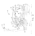
- FIG. 2 a side view of an aft oil sump is shown.
- one or more sumps may be located which service bearings providing for rotation of a radially inner or low pressure shaft 28 and a radially outer shaft or high pressure shaft 26.
- the high pressure shaft 26 interconnects the high pressure turbine 18 and high pressure compressor 14, while the inner shaft interconnects the low pressure compressor and low pressure turbine.
- both shafts will rotate at different speeds relative to each other.
- Both shafts 26, 28 may rotate in the same direction or in opposite directions.
- a high pressure turbine 18 is represented by a rotor assembly 22 which is connected to the high pressure shaft 26 extending about and rotating about the center line axis 24 as well. Also depicted radially below the high pressure shaft 26 is the low pressure shaft 28 which also rotates about the engine axis 24.
- Axially aft of the rotor assembly 22 is an oil sump housing, which is defined by a plurality of structural members 34, 36, 38, 40, 42, 44 and 66. These members generally define a volume 32 above the high pressure shaft 26 wherein oil is retained for cooling and lubrication of at least one shaft bearing, and a sump pressurization cavity comprising volumes 72, 46 and 62 that surrounds the sump 32, through which pressurization air 90 is supplied to the sump seals 68, 70.
- Oil seal 68 may be operatively disposed between a non-rotating structural member of sump 32 (e.g., structural member 44) and shaft 26.
- a sump forward air seal land 50 having a rub strip 52 located along a lower surface thereof.
- a sump forward air labyrinth seal 54 Beneath the sump forward air seal land 50 and engaging the rub strip 52 is a sump forward air labyrinth seal 54.
- Labyrinth seal 54 includes a plurality of seal teeth which extend radially upwardly to engage the rub strip 52.
- Axially aft of the labyrinth seal 54 and extending radially outwardly along an arm 56 is a pathway 58.
- Arm 56 may extend generally radially outwardly from the shaft 26 and/or may rotate with the shaft 26.
- the pressurization tooth 64 may substantially seal the flow path 58 and/or may substantially inhibit air in the lower pressure pathway (e.g., flow path 58), wherein the vortex may be created, from decreasing the pressure on the aft side of the pressurization tooth 64.
- a labyrinth oil seal 68 To the aft of pressurization tooth 64 is a labyrinth oil seal 68, which defines a forward seal for the oil sump 32.
- the aft seal 70 defines the opposite seal for the oil sump 32.
- a bearing assembly 80 for example a roller bearing assembly, which may allow rotation of shaft 26.
- pressurization air 90 moves radially upwardly into a flow path 72 aft of the sump 32.
- the flow 90 moves upwardly through the flow path 72 and through an aperture in the structural member 40 and, for purposes of this description, turns forward relative to the axial direction of the engine 10, toward the windage shield 60.
- the flow 90 passes through a member 66 and moves downwardly through the bypass flow path 62 extending along the aft side of the windage shield 60.
- the vortex created by rotation in the flow area 58 may be substantially separated by the windage shield 60 from the flow 90 moving through the bypass flow path 62.
- the pressure at the flow path area 72 adjacent to aft seal 70 and the pressure at the labyrinth oil seal 68 be close to equal or that the pressure at the labyrinth oil seal 68 be very slightly lower than the pressure at the aft seal 70.
- the air flow 90 at the seal 68 creates a barrier to oil from the sump 32.
- the pressure differential is too high, as was the case with the vortex in path 58, oil from the sump 32 could leak across the labyrinth oil seal 68.
- the pressure differential around the oil sump 32 is minimized, thereby ensuring proper seal performance and inhibiting leakage from the seals.
- FIG. 3 is a detailed view of the labyrinth seal 54 and a windage shield 60 adjacent the oil sump 32.
- the windage shield 60 extends upwardly above a pressurization tooth 64 and may be mounted to a non-rotating structural member of the sump (e.g., structural member 44).
- Axially forward of the windage shield 60 is the flow path 58, which has a varying diameter wherein a vortex may form due to the high speed rotation of the labyrinth seal 54 and arm 56 and varying diameter of path 58.
- the windage shield 60 directs a portion of the flow 90 to the aft side of the shield 60 and through a passage 63, which may be generally radially inwardly oriented. As a result, the vortex in the area of the pathway 58 is inhibited from interacting with the flow path 62 on the aft side of the windage shield 60.
- the pressurization tooth 64 limits the pressure drop associated with the vortex on the forward side of the windage shield 60 from substantially adversely affecting pressure on the aft side of the pressurization tooth 64. This results in higher pressure downstream of passage 63. Pressurization tooth 64 may generally restrict flow of pressurization air 90 therepast.
- pressurized air 90 As the flow of pressurized air 90 moves into the pathway 62 aft of the windage shield 60, some of the pressurized air 90 may turn toward the pressurization tooth 64, move through that seal into the pathway 58, and experience a drop in pressure as it passes through the restriction created by the seal. As the other portion of the flow 90 moves aft toward the labyrinth seal 68, pressure may be substantially maintained at the seal 68 to inhibit oil from sump 32 from moving forward through the seal 68 and leaking. Since the oil seal 68 functions as a seal for the oil sump 32, the pressurized flow 90 on the forward side of the seal 68 inhibits the passage of oil from the aft side of the oil seal 68 to the forward side.
- the windage shield 60 directs pressurized flow 90 to bypass an area 58 wherein a vortex is formed due to rotation. Additionally, the pressurization tooth 64 may prevent the necessarily lower pressure zone on the forward side of the tooth 64 from substantially affecting the static pressure of the air on the aft side of the tooth 64.
- Some example embodiments may include an aperture 65, which may operate as a drain for leaked oil and/or may vent at least some of the pressurization air 90.
- Aperture 65 may be positioned axially between passage 63 and oil seal 68.
- a discourager tooth 74 may be located between passage 63 and labyrinth oil seal 68.
- Discourager tooth 74 may be disposed on shaft 26 and/or may extend radially outwards towards a non-rotating land 76.
- Land 76 may be disposed axially between passage 63 and oil seal 68.
- Discourager tooth 74 may be spaced apart from land 76 in a generally radial direction by a gap 77 having a width 78.
- Discourager tooth 74 may include an upper surface having a width 175.
- Pressurization tooth 64 may have a width 164 which may be measured in a generally axial direction with respect to engine axis 24 ( FIG. 1 ).
- Oil seal 68 may include one or more teeth 69 having a width 169 which may be measured in a generally axial direction with respect to engine axis 24 ( FIG. 1 ).
- the discourager tooth 74 may be at least about 1.5, 2.0, or 2.5 times the width of adjacent teeth on the high pressure shaft 26, such as the pressurization tooth 64 and the exemplary teeth 69 of the labyrinth seal 68.
- discourager tooth width 175 may be at least about 1.5 times pressurization tooth width 164 and/or seal tooth width 169.
- discourager tooth width 175 may be at least about 2.0 times pressurization tooth width 164 and/or seal tooth width 169.
- discourager tooth width 175 may be at least about 2.5 times pressurization tooth width 164 and/or seal tooth width 169.
- a ratio of discourager tooth width 175 to gap width 78 may be greater than about 0.5. In some example embodiments, a ratio of discourager tooth width 175 to gap width 78 may be greater than about 1.0. In some example embodiments, a ratio of discourager tooth width 175 to gap width 78 may be greater than about 4.0.
- embodiments of the instant apparatus provides mitigation of pumping effect in the area of the sump forward air seal 54 and arm 56 and/or minimize pressure loss across the oil sump 32 from the aft seal 70 to the labyrinth oil seal 68.
- pressurization air 90 may be more effectively utilized at the labyrinth seal 68 to deter oil leakage from the sump 32.
- inventive embodiments are presented by way of example only and that, within the scope of the appended claims and equivalents thereto, inventive embodiments may be practiced otherwise than as specifically described and claimed.
- inventive embodiments of the present disclosure are directed to each individual feature, system, article, material, kit, and/or method described herein.
Landscapes
- Engineering & Computer Science (AREA)
- Mechanical Engineering (AREA)
- General Engineering & Computer Science (AREA)
- Chemical & Material Sciences (AREA)
- Combustion & Propulsion (AREA)
- Sealing Using Fluids, Sealing Without Contact, And Removal Of Oil (AREA)
- Turbine Rotor Nozzle Sealing (AREA)
- Sealing Of Bearings (AREA)
Abstract
Description
- The subject matter disclosed herein relates generally to apparatuses and methods for mitigating vortex pumping of pressurization air in a turbine engine. More specifically, not by way of limitation, present embodiments relate to apparatuses and methods for mitigating vortex pumping effect on air pressure around an oil sump of a turbine engine.
- In the turbine engine, air is pressurized in a compressor and mixed with fuel in a combustor for generating hot combustion gases which flow downstream through turbine stages. These turbine stages extract energy from the combustion gases. A high pressure turbine includes a first stage nozzle and a rotor assembly including a disk and a plurality of turbine blades. The high pressure turbine first receives the hot combustion gases from the combustor and includes a first stage stator nozzle that directs the combustion gases downstream through a row of high pressure turbine rotor blades extending radially outwardly from a first rotor disk. In a two stage turbine, a second stage stator nozzle is positioned downstream of the first stage blades followed in turn by a row of second stage turbine blades extending radially outwardly from a second rotor disk. The stator nozzles turn the hot combustion gas in a manner to maximize extraction at the adjacent downstream turbine blades.
- The first and second rotor disks are joined to the compressor by a corresponding rotor shaft for powering the compressor during operation. The turbine engine may include a number of stages of static air foils, commonly referred to as vanes, interspaced in the engine axial direction between rotating air foils commonly referred to as blades. A multi-stage low pressure turbine follows the two stage high pressure turbine and is typically joined by a second shaft to a fan disposed upstream from the compressor in a typical turbo fan aircraft engine configuration for powering an aircraft in flight.
- As the combustion gasses flow downstream through the turbine stages, energy is extracted therefrom and the pressure of the combustion gas is reduced. The combustion gas is used to power the compressor as well as a turbine output shaft for power and marine use or provide thrust in aviation usage. In this manner, fuel energy is converted to mechanical energy of the rotating shaft to power the compressor and supply compressed air needed to continue the process.
- One source of vortices in a turbine engine may be labyrinth seals which can create significant tangential velocity. This may be caused by viscous drag effects from the rotating components of the turbine engine, for example the seal or arm extending to support a seal. In an otherwise non-swirling fluid flow, the creation of these vortices can create significant pressure drop when associated with a change in radius of the swirling fluid. In many cases, such a pressure drop may be highly undesirable.
- In certain oil sumps, minimum pressure differential may be used to prevent oil leakage and such pressure differential may be related to scavenge capability. When the pressure differential around a sump is too high, oil leakage prevention characteristics may be compromised. As utilized in the present disclosure, "pressure differential around a sump" may refer to the maximum difference in air pressure on the dry side of all oil seals for an individual sump.
- In some oil sump configurations, excessive pressure differential around an oil sump may cause undesirable oil leakage.
- At least one solution for the above-mentioned problem(s) is provided by the present disclosure to include example embodiments, provided for illustrative teaching and not meant to be limiting.
- At least some aspects of the present disclosure may involve an oil sump and the reduction of pressure loss upstream of an oil seal due to vortex pumping. Pressurized air flow may be directed away from a pathway wherein vortices may be formed. The pressurized flow may be at least partially isolated from the effect of the vortex on static air pressure by a pressurization tooth seal. Some example embodiments may contribute to maintaining proper air pressure at an adjacent oil sump seal and reducing leakage through that seal.
- An example oil sump seal pressurization apparatus for a turbine engine according to at least some aspects of the present disclosure may include an oil sump comprising at least one bearing mounted therein, the bearing allowing rotation of a shaft with respect to the sump; an oil seal operatively disposed between a non-rotating structural member of the sump and the shaft, the oil sealing having an inward side exposed to an interior of the oil sump and an outward side; a generally radially inwardly oriented passage arranged to supply pressurization air to the outward side of the oil seal; a generally radially outwardly oriented pathway arranged to receive at least some of the pressurization air from the passage, the pathway being at least partially defined by a generally radially outwardly extending arm disposed on the shaft, the arm rotating with the shaft; and/or a windage shield at least partially separating the passage and the pathway, the windage shield being operatively mounted to the non-rotating structural member of the sump.
- An example oil sump seal pressurization apparatus for a turbine engine according to at least some aspects of the present disclosure may include a non-rotating oil sump housing a bearing, the bearing supporting a rotatable shaft; an oil seal at least partially isolating an interior of the oil sump, the oil seal operatively acting between a non-rotating structural member of the sump and the rotatable shaft; a passage arranged to supply pressurization air to an outward side of the oil seal with respect to the oil sump; a sump pressurization cavity disposed at least partially around the oil sump, the sump pressurization cavity comprising a volume arranged to supply the pressurization air to the passage; a non-rotatable windage shield disposed within the sump pressurization cavity between the volume and a rotatable arm disposed on the shaft; and/or a pressurization tooth fluidicly interposing the passage and the rotatable arm, the pressurization tooth restricting flow of the pressurization air from the passage towards the rotatable arm.
- An example oil sump seal pressurization apparatus for a turbine engine according to at least some aspects of the present disclosure may include a non-rotating oil sump housing a bearing, the bearing supporting a rotatable shaft; an oil seal at least partially isolating an interior of the oil sump, the oil seal operatively acting between a non-rotating structural member of the sump and the rotatable shaft; a passage arranged to supply pressurization air to an outward side of the oil seal with respect to the oil sump; a sump pressurization cavity disposed at least partially around the oil sump, the sump pressurization cavity comprising a volume arranged to supply the pressurization air to the passage; a non-rotatable windage shield disposed within the sump pressurization cavity between the volume and a rotatable arm disposed on the shaft; a pressurization tooth fluidicly interposing the passage and the rotatable arm, the pressurization tooth restricting flow of the pressurization air from the passage towards the rotatable arm; and/or a discourager tooth disposed on the shaft and extending radially outward towards a non-rotating land, the land being disposed axially between the passage and the drain, the discourager tooth being spaced apart from the land in a generally radial direction by a gap having a width, the discourager tooth including an upper surface having a width. The pressurization tooth may extend radially outwardly from the shaft generally towards the windage shield. The windage shield may extend generally radially outward with respect to the shaft.
- All of the above outlined features are to be understood as exemplary only and many more features and objectives of the invention may be gleaned from the disclosure herein. Therefore, no limiting interpretation of this summary is to be understood without further reading of the entire specification, claims, and drawings included herewith.
- The subj ect matter for which patent claim coverage is sought is particularly pointed out and claimed herein. The subject matter and embodiments thereof, however, may be best understood by reference to the following description taken in conjunction with the accompanying drawing figures in which:
-
FIG. 1 is a side section view of a gas turbine engine; -
FIG. 2 is a side section view of an example oil sump and related seal structure; and -
FIG. 3 is a detailed view of an example oil sump and related seal structure, all in accordance with at least some aspects of the present disclosure. - In the following detailed description, reference is made to the accompanying drawings, which form a part hereof. In the drawings, similar symbols typically identify similar components, unless context dictates otherwise. The illustrative embodiments described in the detailed description, drawings, and claims are not meant to be limiting. Other embodiments may be utilized, and other changes may be made, without departing from the scope of the subject matter presented here. It will be readily understood that the aspects of the present disclosure, as generally described herein, and illustrated in the figures, can be arranged, substituted, combined, and designed in a wide variety of different configurations, all of which are explicitly contemplated and make part of this disclosure.
- The present disclosure includes, inter alia, gas turbine engines, and, more specifically, apparatuses and methods for mitigating vortex pumping of pressurization air in a turbine engine. Some example embodiments according to at least some aspects of the present disclosure may relate to apparatuses and methods for mitigating vortex pumping effect on air pressure around an oil sump of a turbine engine.
- Reference now will be made in detail to embodiments provided, one or more examples of which are illustrated in the drawings. Each example is provided by way of explanation, not limitation of the disclosed embodiments. In fact, it will be apparent to those skilled in the art that various modifications and variations can be made in the present embodiments without departing from the scope of the disclosure. For instance, features illustrated or described as part of one embodiment can be used with another embodiment to still yield further embodiments. Thus it is intended that the present invention covers such modifications and variations as come within the scope of the appended claims and their equivalents.
- Some example embodiments may apply to gas turbine engines used in connection with aviation, power generation, industrial, or marine uses in which a combustor bums fuel and discharges hot combustion gas into a high pressure turbine. The instant structures and methods may help balance pressure across an oil sump for either a low or a high speed turbine shaft and, more specifically, may limit pressure loss due to vortex pumping of air upstream of an oil seal for the oil sump. Various example embodiments according to at least some aspects of the present disclosure may be applicable to vented as well as non-vented oil sump configurations.
- The terms fore (or forward) and aft are used with respect to the engine axis and generally mean toward the front of the turbine engine or the rear of the turbine engine in the direction of the engine axis.
-
Figures 1-3 illustrate various example oil sump seal pressurization apparatuses and methods of maintaining limited pressure drop across an oil sump, according to at least some embodiments of the present disclosure. Some example embodiments may limit the effect of vortex pumping on static pressure and thereby limit pressure differential around the oil sump. - Referring initially to
FIG. 1 , a schematic side section view of agas turbine engine 10 is shown having anengine inlet end 12, acompressor 14, acombustor 16 and a multi-stagehigh pressure turbine 18. Thegas turbine 10 may be used for aviation, power generation, industrial, marine, or like applications. Thegas turbine 10 is generally axis-symmetrical aboutaxis 24. Depending on the usage, theengine inlet end 12 may alternatively contain multistage compressors rather than a fan. In operation, air enters through theair inlet end 12 of theengine 10 and moves through at least one stage of compression where the air pressure is increased and directed to thecombustor 16. The compressed air is mixed with fuel and burned providing the hot combustion gas which exits acombustor 16 toward thehigh pressure turbine 18. At thehigh pressure turbine 18, energy is extracted from the hot combustion gas causing rotation of turbine blades which in turn cause rotation of thehigh pressure shaft 26, which passes toward the front of the engine to continue rotation of the one ormore compressors 14. A second shaft,low pressure shaft 28, mechanically couples alow pressure turbine 21 and aturbo fan 20 or inlet fan blades, depending on the turbine design. - The
high pressure shaft 26 rotates about theaxis 24 of the engine. Thehigh pressure shaft 26 extends through theturbine engine 10 and is supported by bearings. The bearings operate in oil sumps to cool parts during the high speed revolution. Fluid leakage in and around rotating parts may significantly increase fuel consumption and reduce engine efficiency resulting in undesirable operating parameters for the turbine engine. Additionally, high pressure gasses, such as combustion gasses within the turbine and compressor discharge area, may leak from high pressure areas to low pressure areas and controlling such leakage is preferred. Control or inhibition of such leakage is performed in a variety of manners including, for example, labyrinth seals and brush seals positioned between areas of differential pressure. Over time, however, increased exposure to these high pressure and thermal areas may result in loss of seal effectiveness. - In gas turbine engines it is frequently necessary or desirable to isolate a volume, which may include one or more rotating parts, in order to confine a fluid, such as oil, and to prevent such fluid from flowing into adjacent areas or flowing out of the volume. For example, in a gas turbine engine, it may be necessary to confine a liquid lubricant associated with shaft bearings to a volume surrounding the bearing in order to prevent amounts of the fluid or oil from leaking from the volume or sump. In oil sump structures, pressurized air may be utilized to pass around and/or through the sump area in order to pressurize seals and prevent leakage as well as cool oil or operating components. An
exemplary sump area 30 is depicted at an aft end of theshaft 26. - Some sumps, such as vented and non-vented oil sumps having a plurality of oil seals comprising labyrinth type, carbon type, or other types, may rely on a minimal pressure differential around the sump and/or between the oil seals to limit leakage. When pressure differential is too high, seals may not function appropriately, which may be undesirable. The present disclosure contemplates that, in one structure, a labyrinth seal operating at a high rate of revolution and having an adjacent passage which varies in diameter and extends to a labyrinth oil seal operating at the same rate of revolution but at a smaller diameter may result in a vortex of air upstream of the oil seal. Additionally, the present disclosure contemplates that the decrease of the radius of the vortex created by the rotation of the air near the labyrinth seal may result in pressure loss between the two seals. As a result, it may be difficult to balance the pressure differential between the seals to an acceptable level.
- Referring now to
FIG. 2 , a side view of an aft oil sump is shown. In the aft area of theturbine engine 10, one or more sumps may be located which service bearings providing for rotation of a radially inner orlow pressure shaft 28 and a radially outer shaft orhigh pressure shaft 26. Thehigh pressure shaft 26 interconnects thehigh pressure turbine 18 andhigh pressure compressor 14, while the inner shaft interconnects the low pressure compressor and low pressure turbine. During operation of the turbine engine, both shafts will rotate at different speeds relative to each other. Bothshafts - As shown in
FIG. 2 , at the left-hand side of the page ahigh pressure turbine 18 is represented by arotor assembly 22 which is connected to thehigh pressure shaft 26 extending about and rotating about thecenter line axis 24 as well. Also depicted radially below thehigh pressure shaft 26 is thelow pressure shaft 28 which also rotates about theengine axis 24. - Axially aft of the
rotor assembly 22 is an oil sump housing, which is defined by a plurality ofstructural members volume 32 above thehigh pressure shaft 26 wherein oil is retained for cooling and lubrication of at least one shaft bearing, and a sump pressurizationcavity comprising volumes sump 32, through whichpressurization air 90 is supplied to the sump seals 68, 70.Oil seal 68 may be operatively disposed between a non-rotating structural member of sump 32 (e.g., structural member 44) andshaft 26. Depending frommember 38 is a sump forward air sealland 50 having arub strip 52 located along a lower surface thereof. Beneath the sump forward air sealland 50 and engaging therub strip 52 is a sump forwardair labyrinth seal 54.Labyrinth seal 54 includes a plurality of seal teeth which extend radially upwardly to engage therub strip 52. Axially aft of thelabyrinth seal 54 and extending radially outwardly along anarm 56 is apathway 58.Arm 56 may extend generally radially outwardly from theshaft 26 and/or may rotate with theshaft 26. In thisflow path 58, due to the rotation of thearm 56 and thelabyrinth seal 54, a vortex may be created, which may cause points more radially inward in thepathway 58 to be at relatively lower static pressure than points more radially outward. This variation in pressure may result in a pressure drop if air were to flow radially inwardly throughpathway 58 tooil seal 68. Subsequently, a pressure differential of thepressurization flow 90 around the sump betweenaft seal 70 andforward seal 68 may be realized. Moving axially aft from thewindage shield 60 is abypass flow path 62. Beneath thewindage shield 60 is a tooth seal or a pressurization tooth 64 (e.g., a single tooth). Thepressurization tooth 64 may substantially seal theflow path 58 and/or may substantially inhibit air in the lower pressure pathway (e.g., flow path 58), wherein the vortex may be created, from decreasing the pressure on the aft side of thepressurization tooth 64. To the aft ofpressurization tooth 64 is alabyrinth oil seal 68, which defines a forward seal for theoil sump 32. Theaft seal 70 defines the opposite seal for theoil sump 32. Within thesump 32 is a bearingassembly 80, for example a roller bearing assembly, which may allow rotation ofshaft 26. - As shown in the figure,
pressurization air 90 moves radially upwardly into aflow path 72 aft of thesump 32. Theflow 90 moves upwardly through theflow path 72 and through an aperture in thestructural member 40 and, for purposes of this description, turns forward relative to the axial direction of theengine 10, toward thewindage shield 60. In thestructural member 42, theflow 90 passes through amember 66 and moves downwardly through thebypass flow path 62 extending along the aft side of thewindage shield 60. As a result, the vortex created by rotation in theflow area 58 may be substantially separated by thewindage shield 60 from theflow 90 moving through thebypass flow path 62. - As shown in the figure, it is desirable that the pressure at the
flow path area 72 adjacent toaft seal 70 and the pressure at thelabyrinth oil seal 68 be close to equal or that the pressure at thelabyrinth oil seal 68 be very slightly lower than the pressure at theaft seal 70. Theair flow 90 at theseal 68 creates a barrier to oil from thesump 32. When the pressure differential is too high, as was the case with the vortex inpath 58, oil from thesump 32 could leak across thelabyrinth oil seal 68. Thus, the pressure differential around theoil sump 32 is minimized, thereby ensuring proper seal performance and inhibiting leakage from the seals. -
FIG. 3 is a detailed view of thelabyrinth seal 54 and awindage shield 60 adjacent theoil sump 32. Thewindage shield 60 extends upwardly above apressurization tooth 64 and may be mounted to a non-rotating structural member of the sump (e.g., structural member 44). Axially forward of thewindage shield 60 is theflow path 58, which has a varying diameter wherein a vortex may form due to the high speed rotation of thelabyrinth seal 54 andarm 56 and varying diameter ofpath 58. However, thewindage shield 60 directs a portion of theflow 90 to the aft side of theshield 60 and through apassage 63, which may be generally radially inwardly oriented. As a result, the vortex in the area of thepathway 58 is inhibited from interacting with theflow path 62 on the aft side of thewindage shield 60. - The
pressurization tooth 64 limits the pressure drop associated with the vortex on the forward side of thewindage shield 60 from substantially adversely affecting pressure on the aft side of thepressurization tooth 64. This results in higher pressure downstream ofpassage 63.Pressurization tooth 64 may generally restrict flow ofpressurization air 90 therepast. - As the flow of
pressurized air 90 moves into thepathway 62 aft of thewindage shield 60, some of thepressurized air 90 may turn toward thepressurization tooth 64, move through that seal into thepathway 58, and experience a drop in pressure as it passes through the restriction created by the seal. As the other portion of theflow 90 moves aft toward thelabyrinth seal 68, pressure may be substantially maintained at theseal 68 to inhibit oil fromsump 32 from moving forward through theseal 68 and leaking. Since theoil seal 68 functions as a seal for theoil sump 32, thepressurized flow 90 on the forward side of theseal 68 inhibits the passage of oil from the aft side of theoil seal 68 to the forward side. - As one skilled in the art will understand, the
windage shield 60 directs pressurizedflow 90 to bypass anarea 58 wherein a vortex is formed due to rotation. Additionally, thepressurization tooth 64 may prevent the necessarily lower pressure zone on the forward side of thetooth 64 from substantially affecting the static pressure of the air on the aft side of thetooth 64. - Some example embodiments may include an aperture 65, which may operate as a drain for leaked oil and/or may vent at least some of the
pressurization air 90. Aperture 65 may be positioned axially betweenpassage 63 andoil seal 68. - Referring to
Figures 2 and3 , adiscourager tooth 74 may be located betweenpassage 63 andlabyrinth oil seal 68.Discourager tooth 74 may be disposed onshaft 26 and/or may extend radially outwards towards anon-rotating land 76.Land 76 may be disposed axially betweenpassage 63 andoil seal 68.Discourager tooth 74 may be spaced apart fromland 76 in a generally radial direction by a gap 77 having awidth 78.Discourager tooth 74 may include an upper surface having a width 175.Pressurization tooth 64 may have a width 164 which may be measured in a generally axial direction with respect to engine axis 24 (FIG. 1 ).Oil seal 68 may include one ormore teeth 69 having awidth 169 which may be measured in a generally axial direction with respect to engine axis 24 (FIG. 1 ). - In some example embodiments, the
discourager tooth 74 may be at least about 1.5, 2.0, or 2.5 times the width of adjacent teeth on thehigh pressure shaft 26, such as thepressurization tooth 64 and theexemplary teeth 69 of thelabyrinth seal 68. In other words, in some example embodiments, discourager tooth width 175 may be at least about 1.5 times pressurization tooth width 164 and/or sealtooth width 169. In some example embodiments, discourager tooth width 175 may be at least about 2.0 times pressurization tooth width 164 and/or sealtooth width 169. In some example embodiments, discourager tooth width 175 may be at least about 2.5 times pressurization tooth width 164 and/or sealtooth width 169. - In some example embodiments, a ratio of discourager tooth width 175 to
gap width 78 may be greater than about 0.5. In some example embodiments, a ratio of discourager tooth width 175 togap width 78 may be greater than about 1.0. In some example embodiments, a ratio of discourager tooth width 175 togap width 78 may be greater than about 4.0. - Accordingly, embodiments of the instant apparatus provides mitigation of pumping effect in the area of the sump forward
air seal 54 andarm 56 and/or minimize pressure loss across theoil sump 32 from theaft seal 70 to thelabyrinth oil seal 68. By inhibiting pressure loss across the sump,pressurization air 90 may be more effectively utilized at thelabyrinth seal 68 to deter oil leakage from thesump 32. - While multiple inventive embodiments have been described and illustrated herein, those of ordinary skill in the art will readily envision a variety of other means and/or structures for performing the function and/or obtaining the results and/or one or more of the advantages described herein, and each of such variations and/or modifications is deemed to be within the scope of the invent of embodiments described herein. More generally, those skilled in the art will readily appreciate that all parameters, dimensions, materials, and configurations described herein are meant to be exemplary and that the actual parameters, dimensions, materials, and/or configurations will depend upon the specific application or applications for which the inventive teachings is/are used. Those skilled in the art will recognize, or be able to ascertain using no more than routine experimentation, many equivalents to the specific inventive embodiments described herein. It is, therefore, to be understood that the foregoing embodiments are presented by way of example only and that, within the scope of the appended claims and equivalents thereto, inventive embodiments may be practiced otherwise than as specifically described and claimed. Inventive embodiments of the present disclosure are directed to each individual feature, system, article, material, kit, and/or method described herein. In addition, any combination of two or more such features, systems, articles, materials, kits, and/or methods, if such features, systems, articles, materials, kits, and/or methods are not mutually inconsistent, is included within the inventive scope of the present disclosure.
- Examples are used to disclose the embodiments, including the best mode, and also to enable any person skilled in the art to practice the apparatus and/or method, including making and using any devices or systems and performing any incorporated methods. These examples are not intended to be exhaustive or to limit the disclosure to the precise steps and/or forms disclosed, and many modifications and variations are possible in light of the above teaching. Features described herein may be combined in any combination. Steps of a method described herein may be performed in any sequence that is physically possible.
- All definitions, as defined and used herein, should be understood to control over dictionary definitions, definitions in documents incorporated by reference, and/or ordinary meanings of the defined terms. The indefinite articles "a" and "an," as used herein in the specification and in the claims, unless clearly indicated to the contrary, should be understood to mean "at least one." The phrase "and/or," as used herein in the specification and in the claims, should be understood to mean "either or both" of the elements so conjoined, i.e., elements that are conjunctively present in some cases and disjunctively present in other cases.
- It should also be understood that, unless clearly indicated to the contrary, in any methods claimed herein that include more than one step or act, the order of the steps or acts of the method is not necessarily limited to the order in which the steps or acts of the method are recited.
- In the claims, as well as in the specification above, all transitional phrases such as "comprising," "including," "carrying," "having," "containing," "involving," "holding," "composed of," and the like are to be understood to be open-ended, i.e., to mean including but not limited to.
- This written description uses examples to disclose the invention, including the best mode, and also to enable any person skilled in the art to practice the invention, including making and using any devices or systems and performing any incorporated methods. The patentable scope of the invention is defined by the claims, and may include other examples that occur to those skilled in the art. Such other examples are intended to be within the scope of the claims if they have structural elements that do not differ from the literal language of the claims, or if they include equivalent structural elements with insubstantial differences from the literal languages of the claims.
- Various aspects and embodiments of the present invention are defined by the following numbered clauses:
- 1. An oil sump seal pressurization apparatus for a turbine engine, the oil sump seal pressurization apparatus comprising:
- an oil sump comprising at least one bearing mounted therein, the bearing allowing rotation of a shaft with respect to the sump;
- an oil seal operatively disposed between a non-rotating structural member of the sump and the shaft, the oil sealing having an inward side exposed to an interior of the oil sump and an outward side;
- a generally radially inwardly oriented passage arranged to supply pressurization air to the outward side of the oil seal;
- a generally radially outwardly oriented pathway arranged to receive at least some of the pressurization air from the passage, the pathway being at least partially defined by a generally radially outwardly extending arm disposed on the shaft, the arm rotating with the shaft; and
- a windage shield at least partially separating the passage and the pathway, the windage shield being operatively mounted to the non-rotating structural member of the sump.
- 2. The oil sump seal pressurization apparatus of clause 1, further comprising a pressurization tooth operatively disposed between the passage and the pathway, the pressurization tooth restricting flow of the pressurization air therepast.
- 3. The oil sump seal pressurization apparatus of any preceding clause,
further comprising a discourager tooth disposed on the shaft and extending radially outward towards a non-rotating land, the land being disposed axially between the passage and the oil seal, the discourager tooth being spaced apart from the land in a generally radial direction by a gap having a width, the discourager tooth including an upper surface having a width;
wherein the discourager tooth width is at least about 1.5 times a width of the pressurization tooth. - 4. The oil sump seal pressurization apparatus of any preceding clause, wherein the pressurization tooth extends radially outwardly from the shaft generally towards the windage shield.
- 5. The oil sump seal pressurization apparatus of any preceding clause, wherein the windage shield extends generally radially outward with respect to the shaft.
- 6. The oil sump seal pressurization apparatus of any preceding clause, wherein an air seal is disposed on the arm.
- 7. The oil sump seal pressurization apparatus of any preceding clause, further comprising
a drain arranged to allow draining of oil and venting of at least some of the pressurization air, the drain being positioned axially between the passage and the oil seal; and
a discourager tooth disposed on the shaft and extending radially outward towards a non-rotating land, the land being disposed axially between the passage and the drain, the discourager tooth being spaced apart from the land in a generally radial direction by a gap having a width, the discourager tooth including an upper surface having a width. - 8. The oil sump seal pressurization apparatus of any preceding clause, wherein the discourager tooth width is at least about 2.0 times a width of the pressurization tooth.
- 9. The oil sump seal pressurization apparatus of any preceding clause, wherein a ratio of discourager tooth width to gap width is greater than about 0.5.
- 10. An oil sump seal pressurization apparatus for a turbine engine, the oil sump seal pressurization apparatus comprising
a non-rotating oil sump housing a bearing, the bearing supporting a rotatable shaft;
an oil seal at least partially isolating an interior of the oil sump, the oil seal operatively acting between a non-rotating structural member of the sump and the rotatable shaft;
a passage arranged to supply pressurization air to an outward side of the oil seal with respect to the oil sump;
a sump pressurization cavity disposed at least partially around the oil sump, the sump pressurization cavity comprising a volume arranged to supply the pressurization air to the passage;
a non-rotatable windage shield disposed within the sump pressurization cavity between the volume and a rotatable arm disposed on the shaft; and
a pressurization tooth fluidicly interposing the passage and the rotatable arm, the pressurization tooth restricting flow of the pressurization air from the passage towards the rotatable arm. - 11. The oil sump seal pressurization apparatus of any preceding clause, wherein the pressurization tooth extends radially outwardly from the shaft generally towards the windage shield.
- 12. The oil sump seal pressurization apparatus of any preceding clause, wherein the windage shield extends generally radially outward with respect to the shaft.
- 13. The oil sump seal pressurization apparatus of any preceding clause, wherein an air seal is disposed on the arm.
- 14. The oil sump seal pressurization apparatus of any preceding clause,
further comprising a discourager tooth disposed on the shaft and extending radially outward towards a non-rotating land, the land being disposed axially between the passage and the oil seal, the discourager tooth being spaced apart from the land in a generally radial direction by a gap having a width, the discourager tooth including an upper surface having a width; - 15. The oil sump seal pressurization apparatus of any preceding clause, wherein the discourager tooth width is at least about 1.5 times a width of the pressurization tooth.
- 16. An oil sump seal pressurization apparatus for a turbine engine, the oil sump seal pressurization apparatus comprising
a non-rotating oil sump housing a bearing, the bearing supporting a rotatable shaft;
an oil seal at least partially isolating an interior of the oil sump, the oil seal operatively acting between a non-rotating structural member of the sump and the rotatable shaft;
a passage arranged to supply pressurization air to an outward side of the oil seal with respect to the oil sump;
a sump pressurization cavity disposed at least partially around the oil sump, the sump pressurization cavity comprising a volume arranged to supply the pressurization air to the passage;
a non-rotatable windage shield disposed within the sump pressurization cavity between the volume and a rotatable arm disposed on the shaft;
a pressurization tooth fluidicly interposing the passage and the rotatable arm, the pressurization tooth restricting flow of the pressurization air from the passage towards the rotatable arm; and
a discourager tooth disposed on the shaft and extending radially outward towards a non-rotating land, the land being disposed axially between the passage and the drain, the discourager tooth being spaced apart from the land in a generally radial direction by a gap having a width, the discourager tooth including an upper surface having a width;
wherein the pressurization tooth extends radially outwardly from the shaft generally towards the windage shield; and
wherein the windage shield extends generally radially outward with respect to the shaft. - 17. The oil sump seal pressurization apparatus of any preceding clause, further comprising a drain arranged to allow draining of oil and venting of at least some of the pressurization air, the drain being positioned axially between the passage and the oil seal.
- 18. The oil sump seal pressurization apparatus of any preceding clause, wherein the discourager tooth width is at least about 1.5 times a width of the pressurization tooth.
- 19. The oil sump seal pressurization apparatus of any preceding clause, wherein the discourager tooth width is at least about 2.0 times a width of the pressurization tooth.
- 20. The oil sump seal pressurization apparatus of any preceding clause, wherein the discourager tooth width is at least about 2.5 times a width of the pressurization tooth.
Claims (15)
- An oil sump seal pressurization apparatus for a turbine engine (10), the oil sump seal pressurization apparatus comprising:an oil sump (32) comprising at least one bearing (80) mounted therein, the bearing allowing rotation of a shaft (26) with respect to the sump;an oil seal (68) operatively disposed between a non-rotating structural member (44) of the sump and the shaft, the oil seal having an inward side exposed to an interior of the oil sump and an outward side;a generally radially inwardly oriented passage (62) arranged to supply pressurization air (90) to the outward side of the oil seal;a generally radially outwardly oriented pathway (58) arranged to receive at least some of the pressurization air from the passage, the pathway being at least partially defined by a generally radially outwardly extending arm (56) disposed on the shaft (26), the arm rotating with the shaft; anda windage shield (60) at least partially separating the passage (62) and the pathway (58), the windage shield being operatively mounted to the non-rotating structural member of the sump.
- The oil sump seal pressurization apparatus of claim 1, further comprising a pressurization tooth (64) operatively disposed between the passage (62) and the pathway (58), the pressurization tooth restricting flow of the pressurization air therepast.
- The oil sump seal pressurization apparatus of claim 2,
further comprising a discourager tooth (74) disposed on the shaft (26) and extending radially outward towards a non-rotating land (76), the land being disposed axially between the passage (62) and the oil seal (68), the discourager tooth being spaced apart from the land in a generally radial direction by a gap (77) having a width (78), the discourager tooth including an upper surface having a width (175);
wherein the discourager tooth width is at least about 1.5 times a width (164) of the pressurization tooth. - The oil sump seal pressurization apparatus of any of the preceding claims, wherein the pressurization tooth (64) extends radially outwardly from the shaft (26) generally towards the windage shield (60).
- The oil sump seal pressurization apparatus of any of the preceding claims, wherein the windage shield (60) extends generally radially outward with respect to the shaft (26).
- The oil sump seal pressurization apparatus of any of the preceding claims, wherein an air seal (54) is disposed on the arm (56).
- The oil sump seal pressurization apparatus of either of claim 1 or claim 2, further comprising:a drain (65) arranged to allow draining of oil and venting of at least some of the pressurization air (90), the drain being positioned axially between the passage (62) and the oil seal (68); anda discourager tooth (74) disposed on the shaft (26) and extending radially outward towards a non-rotating land (76), the land being disposed axially between the passage (62) and the drain (65), the discourager tooth being spaced apart from the land in a generally radial direction by a gap (77) having a width (78), the discourager tooth including an upper surface having a width (175).
- The oil sump seal pressurization apparatus of claim 7, wherein the discourager tooth width (175) is at least about 2.0 times a width (164) of the pressurization tooth (64).
- The oil sump seal pressurization apparatus of either of claim 7 or 8, wherein a ratio of discourager tooth width (175) to gap width (78) is greater than about 0.5.
- The oil sump seal pressurization apparatus of claim 1, further comprising:a sump pressurization cavity (72,46,62) disposed at least partially around the oil sump (32), the sump pressurization cavity comprising a volume arranged to supply the pressurization air (90) to the passage (62); anda pressurization tooth (64) fluidicly interposing the passage and the rotatable arm (56), the pressurization tooth restricting flow of the pressurization air from the passage towards the rotatable arm.
- The oil sump seal pressurization apparatus of claim 10, wherein the pressurization tooth (64) extends radially outwardly from the shaft (26) generally towards the windage shield (60).
- The oil sump seal pressurization apparatus of either of claim 10 or 11, wherein the windage shield (60) extends generally radially outward with respect to the shaft (26).
- The oil sump seal pressurization apparatus of any one of claims 10 to 12, wherein an air seal (54) is disposed on the arm (56).
- The oil sump seal pressurization apparatus of any one of claims 10 to 13,
further comprising a discourager tooth (74) disposed on the shaft (26) and extending radially outward towards a non-rotating land (76), the land being disposed axially between the passage (62) and the oil seal (68), the discourager tooth being spaced apart from the land in a generally radial direction by a gap (77) having a width (78), the discourager tooth including an upper surface having a width (175). - The oil sump seal pressurization apparatus of claim 14, wherein the discourager tooth width (175) is at least about 1.5 times a width of the pressurization tooth (64).
Applications Claiming Priority (2)
| Application Number | Priority Date | Filing Date | Title |
|---|---|---|---|
| US201261639315P | 2012-04-27 | 2012-04-27 | |
| US13/713,013 US9567908B2 (en) | 2012-04-27 | 2012-12-13 | Mitigating vortex pumping effect upstream of oil seal |
Publications (2)
| Publication Number | Publication Date |
|---|---|
| EP2657465A1 true EP2657465A1 (en) | 2013-10-30 |
| EP2657465B1 EP2657465B1 (en) | 2015-06-10 |
Family
ID=48182827
Family Applications (1)
| Application Number | Title | Priority Date | Filing Date |
|---|---|---|---|
| EP13165398.2A Not-in-force EP2657465B1 (en) | 2012-04-27 | 2013-04-25 | Mitigating Vortex Pumping Effect Upstream of Oil Seal |
Country Status (5)
| Country | Link |
|---|---|
| US (1) | US9567908B2 (en) |
| EP (1) | EP2657465B1 (en) |
| JP (1) | JP6169879B2 (en) |
| CN (1) | CN103375192B (en) |
| CA (1) | CA2813341A1 (en) |
Cited By (4)
| Publication number | Priority date | Publication date | Assignee | Title |
|---|---|---|---|---|
| EP2657464A3 (en) * | 2012-04-27 | 2014-05-21 | General Electric Company | Wide discourager tooth for lubricant oil in a turbine |
| US9567908B2 (en) | 2012-04-27 | 2017-02-14 | General Electric Company | Mitigating vortex pumping effect upstream of oil seal |
| EP3244026A1 (en) * | 2016-04-29 | 2017-11-15 | General Electric Company | Sump assembly for a gas turbine engine |
| EP3623589A1 (en) * | 2018-09-11 | 2020-03-18 | United Technologies Corporation | Bearing compartment oil auto-ignition mitigation |
Families Citing this family (34)
| Publication number | Priority date | Publication date | Assignee | Title |
|---|---|---|---|---|
| FR2992679A1 (en) * | 2012-06-28 | 2014-01-03 | Snecma | TURBOMACHINE SWING COMPRISING A CROWN FOR RECOVERING A LUBRICATING OIL FLOW WITH A PLURALITY OF LUBRICATING OIL VACUUM ORIFICES |
| WO2014109787A1 (en) * | 2013-01-10 | 2014-07-17 | United Technologies Corporation | Two spool gas generator with mount ring |
| US10077830B2 (en) | 2013-12-16 | 2018-09-18 | United Technologies Corporation | Transfer bearing for geared turbofan |
| US10502094B2 (en) * | 2014-07-22 | 2019-12-10 | United Technologies Corporation | Bearing compartment sealing system with passive cooling |
| US9944399B2 (en) | 2014-08-07 | 2018-04-17 | Pratt & Whitney Canada Corp. | Seal assembly for a bearing assembly in a gas turbine engine |
| US10288163B2 (en) * | 2015-10-23 | 2019-05-14 | General Electric Company | Method and system for a planetary power gearbox static to rotating oil transfer supply |
| US10385729B2 (en) | 2015-11-24 | 2019-08-20 | General Electric Company | Cylindrical air guide in a turbine engine |
| CA2957467A1 (en) * | 2016-02-24 | 2017-08-24 | General Electric Company | Turbine engine ejector throat control |
| US10344869B2 (en) * | 2016-05-31 | 2019-07-09 | Rolls-Royce Corporation | Labyrinth seal with lubricant directing projection |
| US10823061B2 (en) | 2016-07-15 | 2020-11-03 | General Electric Company | Engine air inlet having a double-panel heated wall |
| FR3062679B1 (en) * | 2017-02-07 | 2019-04-19 | Safran Aircraft Engines | VIROLE FOR REDUCING THE PRESSURE REDUCTION IN THE NEIGHBORHOOD OF THE UPPER JOINT OF A TURBOJET ENGINE BEARING ENCLOSURE |
| US10359117B2 (en) * | 2017-03-06 | 2019-07-23 | General Electric Company | Aspirating face seal with non-coiled retraction springs |
| US10260418B2 (en) * | 2017-03-20 | 2019-04-16 | General Electric Company | Evaporative cooling systems and methods |
| US10329938B2 (en) * | 2017-05-31 | 2019-06-25 | General Electric Company | Aspirating face seal starter tooth abradable pocket |
| US10458267B2 (en) | 2017-09-20 | 2019-10-29 | General Electric Company | Seal assembly for counter rotating turbine assembly |
| US10711629B2 (en) | 2017-09-20 | 2020-07-14 | Generl Electric Company | Method of clearance control for an interdigitated turbine engine |
| US11306614B2 (en) * | 2018-10-04 | 2022-04-19 | Rolls-Royce Corporation | Sump auxiliary vent system |
| US10648510B1 (en) * | 2018-10-17 | 2020-05-12 | Pratt & Whitney Canada Corp. | Baffle for installation inside a bearing chamber of a gas turbine engine |
| US11248492B2 (en) * | 2019-03-18 | 2022-02-15 | Raytheon Technologies Corporation | Seal assembly for a gas turbine engine |
| US11293295B2 (en) * | 2019-09-13 | 2022-04-05 | Pratt & Whitney Canada Corp. | Labyrinth seal with angled fins |
| US11255264B2 (en) | 2020-02-25 | 2022-02-22 | General Electric Company | Frame for a heat engine |
| US11326519B2 (en) | 2020-02-25 | 2022-05-10 | General Electric Company | Frame for a heat engine |
| US11560843B2 (en) | 2020-02-25 | 2023-01-24 | General Electric Company | Frame for a heat engine |
| US11293351B2 (en) * | 2020-07-16 | 2022-04-05 | Raytheon Technologies Corporation | Gas turbine engine including seal assembly with abradable coating including magnetic particles embedded in polymer |
| US11313280B2 (en) * | 2020-07-16 | 2022-04-26 | Raytheon Technologies Corporation | Gas turbine engine including seal assembly with abradable coating and cutter |
| US11313281B2 (en) * | 2020-07-16 | 2022-04-26 | Raytheon Technologies Corporation | Gas turbine engine including seal assembly with abradable coating including magnetic particles |
| FR3114836B1 (en) * | 2020-10-01 | 2022-09-02 | Safran Aircraft Engines | STATOR SUPPORT FOR A FAN SHAFT DRIVEN BY A GEARBOX IN A TURBOMACHINE |
| US11846355B2 (en) | 2020-10-16 | 2023-12-19 | Rtx Corporation | Dual windage blocker and retention feature design for seal assembly |
| US11428160B2 (en) | 2020-12-31 | 2022-08-30 | General Electric Company | Gas turbine engine with interdigitated turbine and gear assembly |
| FR3118989B1 (en) * | 2021-01-21 | 2023-03-03 | Safran Aircraft Engines | Ventilation crown of the rear bearing support of an aircraft turbomachine |
| US11365682B1 (en) | 2021-03-04 | 2022-06-21 | Rolls-Royce North American Technologies Inc. | Gas turbine engine cooled sump buffer air system |
| FR3132939B1 (en) * | 2022-02-21 | 2024-02-09 | Safran Aircraft Engines | Sealing and oil leak drainage system for turbomachine bearing enclosure |
| US11867064B1 (en) | 2022-09-26 | 2024-01-09 | Pratt & Whitney Canada Corp. | Seal assembly for aircraft engine |
| US12595747B2 (en) * | 2023-07-20 | 2026-04-07 | Pratt & Whitney Canada Corp. | Method of mitigating vibrations in a seal component |
Citations (3)
| Publication number | Priority date | Publication date | Assignee | Title |
|---|---|---|---|---|
| US3528241A (en) * | 1969-02-24 | 1970-09-15 | Gen Electric | Gas turbine engine lubricant sump vent and circulating system |
| GB2152148A (en) * | 1983-12-23 | 1985-07-31 | United Technologies Corp | Controlling bearing chamber temperature in gas turbine engine |
| EP1820944A2 (en) * | 2006-02-21 | 2007-08-22 | General Electric Company | Supercore sump vent pressure control |
Family Cites Families (33)
| Publication number | Priority date | Publication date | Assignee | Title |
|---|---|---|---|---|
| US3085809A (en) * | 1960-04-14 | 1963-04-16 | Gen Electric | Labyrinth seal |
| US3537713A (en) | 1968-02-21 | 1970-11-03 | Garrett Corp | Wear-resistant labyrinth seal |
| US3501089A (en) * | 1968-07-17 | 1970-03-17 | Gen Electric | Jet pump ejector |
| US3527054A (en) * | 1969-01-23 | 1970-09-08 | Gen Electric | Pressurization of lubrication sumps in gas turbine engines |
| US3989410A (en) * | 1974-11-27 | 1976-11-02 | General Electric Company | Labyrinth seal system |
| US4190397A (en) * | 1977-11-23 | 1980-02-26 | General Electric Company | Windage shield |
| US4397471A (en) | 1981-09-02 | 1983-08-09 | General Electric Company | Rotary pressure seal structure and method for reducing thermal stresses therein |
| CA1238618A (en) | 1983-12-14 | 1988-06-28 | Masahito Mitsumori | Vane pump |
| US4645415A (en) * | 1983-12-23 | 1987-02-24 | United Technologies Corporation | Air cooler for providing buffer air to a bearing compartment |
| US5090865A (en) | 1990-10-22 | 1992-02-25 | General Electric Company | Windage shield |
| US5190440A (en) | 1991-03-11 | 1993-03-02 | Dresser-Rand Company | Swirl control labyrinth seal |
| US5218816A (en) | 1992-01-28 | 1993-06-15 | General Electric Company | Seal exit flow discourager |
| US5301957A (en) * | 1992-04-27 | 1994-04-12 | General Electric Company | Expanding circumferential seal with upper-cooled runner |
| US5619850A (en) * | 1995-05-09 | 1997-04-15 | Alliedsignal Inc. | Gas turbine engine with bleed air buffer seal |
| US6330790B1 (en) * | 1999-10-27 | 2001-12-18 | Alliedsignal, Inc. | Oil sump buffer seal |
| US6398486B1 (en) | 2000-06-01 | 2002-06-04 | General Electric Company | Steam exit flow design for aft cavities of an airfoil |
| US6350102B1 (en) | 2000-07-19 | 2002-02-26 | General Electric Company | Shroud leakage flow discouragers |
| US6761034B2 (en) | 2000-12-08 | 2004-07-13 | General Electroc Company | Structural cover for gas turbine engine bolted flanges |
| US6481959B1 (en) | 2001-04-26 | 2002-11-19 | Honeywell International, Inc. | Gas turbine disk cavity ingestion inhibitor |
| US6470666B1 (en) * | 2001-04-30 | 2002-10-29 | General Electric Company | Methods and systems for preventing gas turbine engine lube oil leakage |
| US6565095B2 (en) * | 2001-07-12 | 2003-05-20 | Honeywell International, Inc. | Face seal with internal drain |
| US20030097872A1 (en) * | 2001-11-29 | 2003-05-29 | Granitz Charles Robert | System for reducing oil consumption in gas turbine engines |
| US6679045B2 (en) * | 2001-12-18 | 2004-01-20 | General Electric Company | Flexibly coupled dual shell bearing housing |
| JP2003214112A (en) * | 2002-01-21 | 2003-07-30 | Ishikawajima Harima Heavy Ind Co Ltd | Engine for aircraft |
| US7677048B1 (en) | 2006-05-24 | 2010-03-16 | Florida Turbine Technologies, Inc. | Turbine last stage blade with forced vortex driven cooling air |
| US20080041064A1 (en) | 2006-08-17 | 2008-02-21 | United Technologies Corporation | Preswirl pollution air handling with tangential on-board injector for turbine rotor cooling |
| US7500824B2 (en) | 2006-08-22 | 2009-03-10 | General Electric Company | Angel wing abradable seal and sealing method |
| US8210316B2 (en) | 2006-12-12 | 2012-07-03 | United Technologies Corporation | Oil scavenge system for a gas turbine engine |
| US8353668B2 (en) | 2009-02-18 | 2013-01-15 | United Technologies Corporation | Airfoil insert having a tab extending away from the body defining a portion of outlet periphery |
| US20100254807A1 (en) | 2009-04-07 | 2010-10-07 | Honeywell International Inc. | Turbine rotor seal plate with integral flow discourager |
| US8360712B2 (en) * | 2010-01-22 | 2013-01-29 | General Electric Company | Method and apparatus for labyrinth seal packing rings |
| US9353647B2 (en) * | 2012-04-27 | 2016-05-31 | General Electric Company | Wide discourager tooth |
| US9567908B2 (en) | 2012-04-27 | 2017-02-14 | General Electric Company | Mitigating vortex pumping effect upstream of oil seal |
-
2012
- 2012-12-13 US US13/713,013 patent/US9567908B2/en not_active Expired - Fee Related
-
2013
- 2013-04-18 CA CA2813341A patent/CA2813341A1/en not_active Abandoned
- 2013-04-25 EP EP13165398.2A patent/EP2657465B1/en not_active Not-in-force
- 2013-04-25 JP JP2013091862A patent/JP6169879B2/en not_active Expired - Fee Related
- 2013-04-26 CN CN201310149679.6A patent/CN103375192B/en active Active
Patent Citations (3)
| Publication number | Priority date | Publication date | Assignee | Title |
|---|---|---|---|---|
| US3528241A (en) * | 1969-02-24 | 1970-09-15 | Gen Electric | Gas turbine engine lubricant sump vent and circulating system |
| GB2152148A (en) * | 1983-12-23 | 1985-07-31 | United Technologies Corp | Controlling bearing chamber temperature in gas turbine engine |
| EP1820944A2 (en) * | 2006-02-21 | 2007-08-22 | General Electric Company | Supercore sump vent pressure control |
Cited By (7)
| Publication number | Priority date | Publication date | Assignee | Title |
|---|---|---|---|---|
| EP2657464A3 (en) * | 2012-04-27 | 2014-05-21 | General Electric Company | Wide discourager tooth for lubricant oil in a turbine |
| US9353647B2 (en) | 2012-04-27 | 2016-05-31 | General Electric Company | Wide discourager tooth |
| US9567908B2 (en) | 2012-04-27 | 2017-02-14 | General Electric Company | Mitigating vortex pumping effect upstream of oil seal |
| EP3244026A1 (en) * | 2016-04-29 | 2017-11-15 | General Electric Company | Sump assembly for a gas turbine engine |
| US10221766B2 (en) | 2016-04-29 | 2019-03-05 | General Electric Company | Sump assembly for a gas turbine engine |
| EP3623589A1 (en) * | 2018-09-11 | 2020-03-18 | United Technologies Corporation | Bearing compartment oil auto-ignition mitigation |
| US10767560B2 (en) | 2018-09-11 | 2020-09-08 | Raytheon Technologies Corporation | Bearing compartment oil auto-ignition mitigation |
Also Published As
| Publication number | Publication date |
|---|---|
| EP2657465B1 (en) | 2015-06-10 |
| US20130283757A1 (en) | 2013-10-31 |
| US9567908B2 (en) | 2017-02-14 |
| JP6169879B2 (en) | 2017-07-26 |
| CA2813341A1 (en) | 2013-10-27 |
| JP2013231434A (en) | 2013-11-14 |
| CN103375192A (en) | 2013-10-30 |
| CN103375192B (en) | 2016-08-10 |
Similar Documents
| Publication | Publication Date | Title |
|---|---|---|
| EP2657465B1 (en) | Mitigating Vortex Pumping Effect Upstream of Oil Seal | |
| US9353647B2 (en) | Wide discourager tooth | |
| US10036508B2 (en) | Flow vortex spoiler | |
| EP3460185A1 (en) | Seal assembly for counter rotating turbine assembly | |
| EP3318722B1 (en) | Seal assembly for a rotatable component | |
| US10502081B2 (en) | Turbomachine bearing housing | |
| US9022390B2 (en) | Threaded seal for a gas turbine engine | |
| US9903224B2 (en) | Scupper channelling in gas turbine modules | |
| US9657642B2 (en) | Turbine sections of gas turbine engines with dual use of cooling air | |
| RU2584365C2 (en) | Air bleed system for axial turbine machine | |
| CA2895157A1 (en) | Pressure fed oil drain for gas turbine engine sump | |
| US10612436B2 (en) | Deoiler for a gas turbine engine | |
| US20190226585A1 (en) | Hydrodynamic Intershaft Piston Ring Seal | |
| US10598035B2 (en) | Intershaft sealing systems for gas turbine engines and methods for assembling the same | |
| US10533445B2 (en) | Rim seal for gas turbine engine | |
| US10648510B1 (en) | Baffle for installation inside a bearing chamber of a gas turbine engine | |
| CN117988936A (en) | Rotating machine seal having a wear protection assembly with an abradable cover |
Legal Events
| Date | Code | Title | Description |
|---|---|---|---|
| PUAI | Public reference made under article 153(3) epc to a published international application that has entered the european phase |
Free format text: ORIGINAL CODE: 0009012 |
|
| AK | Designated contracting states |
Kind code of ref document: A1 Designated state(s): AL AT BE BG CH CY CZ DE DK EE ES FI FR GB GR HR HU IE IS IT LI LT LU LV MC MK MT NL NO PL PT RO RS SE SI SK SM TR |
|
| AX | Request for extension of the european patent |
Extension state: BA ME |
|
| 17P | Request for examination filed |
Effective date: 20140430 |
|
| RBV | Designated contracting states (corrected) |
Designated state(s): AL AT BE BG CH CY CZ DE DK EE ES FI FR GB GR HR HU IE IS IT LI LT LU LV MC MK MT NL NO PL PT RO RS SE SI SK SM TR |
|
| RIC1 | Information provided on ipc code assigned before grant |
Ipc: F01D 25/12 20060101ALI20141218BHEP Ipc: F01D 25/18 20060101AFI20141218BHEP Ipc: F02C 7/06 20060101ALI20141218BHEP |
|
| GRAP | Despatch of communication of intention to grant a patent |
Free format text: ORIGINAL CODE: EPIDOSNIGR1 |
|
| INTG | Intention to grant announced |
Effective date: 20150122 |
|
| GRAS | Grant fee paid |
Free format text: ORIGINAL CODE: EPIDOSNIGR3 |
|
| GRAA | (expected) grant |
Free format text: ORIGINAL CODE: 0009210 |
|
| AK | Designated contracting states |
Kind code of ref document: B1 Designated state(s): AL AT BE BG CH CY CZ DE DK EE ES FI FR GB GR HR HU IE IS IT LI LT LU LV MC MK MT NL NO PL PT RO RS SE SI SK SM TR |
|
| REG | Reference to a national code |
Ref country code: GB Ref legal event code: FG4D |
|
| REG | Reference to a national code |
Ref country code: CH Ref legal event code: EP |
|
| REG | Reference to a national code |
Ref country code: AT Ref legal event code: REF Ref document number: 730997 Country of ref document: AT Kind code of ref document: T Effective date: 20150715 |
|
| REG | Reference to a national code |
Ref country code: DE Ref legal event code: R096 Ref document number: 602013001963 Country of ref document: DE |
|
| REG | Reference to a national code |
Ref country code: IE Ref legal event code: FG4D |
|
| PG25 | Lapsed in a contracting state [announced via postgrant information from national office to epo] |
Ref country code: LT Free format text: LAPSE BECAUSE OF FAILURE TO SUBMIT A TRANSLATION OF THE DESCRIPTION OR TO PAY THE FEE WITHIN THE PRESCRIBED TIME-LIMIT Effective date: 20150610 Ref country code: FI Free format text: LAPSE BECAUSE OF FAILURE TO SUBMIT A TRANSLATION OF THE DESCRIPTION OR TO PAY THE FEE WITHIN THE PRESCRIBED TIME-LIMIT Effective date: 20150610 Ref country code: NO Free format text: LAPSE BECAUSE OF FAILURE TO SUBMIT A TRANSLATION OF THE DESCRIPTION OR TO PAY THE FEE WITHIN THE PRESCRIBED TIME-LIMIT Effective date: 20150910 Ref country code: ES Free format text: LAPSE BECAUSE OF FAILURE TO SUBMIT A TRANSLATION OF THE DESCRIPTION OR TO PAY THE FEE WITHIN THE PRESCRIBED TIME-LIMIT Effective date: 20150610 |
|
| REG | Reference to a national code |
Ref country code: AT Ref legal event code: MK05 Ref document number: 730997 Country of ref document: AT Kind code of ref document: T Effective date: 20150610 |
|
| REG | Reference to a national code |
Ref country code: NL Ref legal event code: MP Effective date: 20150610 |
|
| PG25 | Lapsed in a contracting state [announced via postgrant information from national office to epo] |
Ref country code: LV Free format text: LAPSE BECAUSE OF FAILURE TO SUBMIT A TRANSLATION OF THE DESCRIPTION OR TO PAY THE FEE WITHIN THE PRESCRIBED TIME-LIMIT Effective date: 20150610 Ref country code: GR Free format text: LAPSE BECAUSE OF FAILURE TO SUBMIT A TRANSLATION OF THE DESCRIPTION OR TO PAY THE FEE WITHIN THE PRESCRIBED TIME-LIMIT Effective date: 20150911 Ref country code: RS Free format text: LAPSE BECAUSE OF FAILURE TO SUBMIT A TRANSLATION OF THE DESCRIPTION OR TO PAY THE FEE WITHIN THE PRESCRIBED TIME-LIMIT Effective date: 20150610 Ref country code: BG Free format text: LAPSE BECAUSE OF FAILURE TO SUBMIT A TRANSLATION OF THE DESCRIPTION OR TO PAY THE FEE WITHIN THE PRESCRIBED TIME-LIMIT Effective date: 20150910 |
|
| PG25 | Lapsed in a contracting state [announced via postgrant information from national office to epo] |
Ref country code: EE Free format text: LAPSE BECAUSE OF FAILURE TO SUBMIT A TRANSLATION OF THE DESCRIPTION OR TO PAY THE FEE WITHIN THE PRESCRIBED TIME-LIMIT Effective date: 20150610 |
|
| PG25 | Lapsed in a contracting state [announced via postgrant information from national office to epo] |
Ref country code: PT Free format text: LAPSE BECAUSE OF FAILURE TO SUBMIT A TRANSLATION OF THE DESCRIPTION OR TO PAY THE FEE WITHIN THE PRESCRIBED TIME-LIMIT Effective date: 20151012 Ref country code: IS Free format text: LAPSE BECAUSE OF FAILURE TO SUBMIT A TRANSLATION OF THE DESCRIPTION OR TO PAY THE FEE WITHIN THE PRESCRIBED TIME-LIMIT Effective date: 20151010 Ref country code: AT Free format text: LAPSE BECAUSE OF FAILURE TO SUBMIT A TRANSLATION OF THE DESCRIPTION OR TO PAY THE FEE WITHIN THE PRESCRIBED TIME-LIMIT Effective date: 20150610 Ref country code: RO Free format text: LAPSE BECAUSE OF NON-PAYMENT OF DUE FEES Effective date: 20150610 Ref country code: SK Free format text: LAPSE BECAUSE OF FAILURE TO SUBMIT A TRANSLATION OF THE DESCRIPTION OR TO PAY THE FEE WITHIN THE PRESCRIBED TIME-LIMIT Effective date: 20150610 Ref country code: PL Free format text: LAPSE BECAUSE OF FAILURE TO SUBMIT A TRANSLATION OF THE DESCRIPTION OR TO PAY THE FEE WITHIN THE PRESCRIBED TIME-LIMIT Effective date: 20150610 Ref country code: CZ Free format text: LAPSE BECAUSE OF FAILURE TO SUBMIT A TRANSLATION OF THE DESCRIPTION OR TO PAY THE FEE WITHIN THE PRESCRIBED TIME-LIMIT Effective date: 20150610 |
|
| REG | Reference to a national code |
Ref country code: DE Ref legal event code: R097 Ref document number: 602013001963 Country of ref document: DE |
|
| PLBE | No opposition filed within time limit |
Free format text: ORIGINAL CODE: 0009261 |
|
| STAA | Information on the status of an ep patent application or granted ep patent |
Free format text: STATUS: NO OPPOSITION FILED WITHIN TIME LIMIT |
|
| REG | Reference to a national code |
Ref country code: FR Ref legal event code: PLFP Year of fee payment: 4 |
|
| PG25 | Lapsed in a contracting state [announced via postgrant information from national office to epo] |
Ref country code: IT Free format text: LAPSE BECAUSE OF FAILURE TO SUBMIT A TRANSLATION OF THE DESCRIPTION OR TO PAY THE FEE WITHIN THE PRESCRIBED TIME-LIMIT Effective date: 20150610 Ref country code: DK Free format text: LAPSE BECAUSE OF FAILURE TO SUBMIT A TRANSLATION OF THE DESCRIPTION OR TO PAY THE FEE WITHIN THE PRESCRIBED TIME-LIMIT Effective date: 20150610 |
|
| 26N | No opposition filed |
Effective date: 20160311 |
|
| PG25 | Lapsed in a contracting state [announced via postgrant information from national office to epo] |
Ref country code: SI Free format text: LAPSE BECAUSE OF FAILURE TO SUBMIT A TRANSLATION OF THE DESCRIPTION OR TO PAY THE FEE WITHIN THE PRESCRIBED TIME-LIMIT Effective date: 20150610 |
|
| PG25 | Lapsed in a contracting state [announced via postgrant information from national office to epo] |
Ref country code: BE Free format text: LAPSE BECAUSE OF NON-PAYMENT OF DUE FEES Effective date: 20160430 |
|
| REG | Reference to a national code |
Ref country code: CH Ref legal event code: PL |
|
| PG25 | Lapsed in a contracting state [announced via postgrant information from national office to epo] |
Ref country code: LU Free format text: LAPSE BECAUSE OF FAILURE TO SUBMIT A TRANSLATION OF THE DESCRIPTION OR TO PAY THE FEE WITHIN THE PRESCRIBED TIME-LIMIT Effective date: 20160425 Ref country code: BE Free format text: LAPSE BECAUSE OF FAILURE TO SUBMIT A TRANSLATION OF THE DESCRIPTION OR TO PAY THE FEE WITHIN THE PRESCRIBED TIME-LIMIT Effective date: 20150610 |
|
| REG | Reference to a national code |
Ref country code: IE Ref legal event code: MM4A |
|
| PG25 | Lapsed in a contracting state [announced via postgrant information from national office to epo] |
Ref country code: CH Free format text: LAPSE BECAUSE OF NON-PAYMENT OF DUE FEES Effective date: 20160430 Ref country code: LI Free format text: LAPSE BECAUSE OF NON-PAYMENT OF DUE FEES Effective date: 20160430 |
|
| REG | Reference to a national code |
Ref country code: FR Ref legal event code: PLFP Year of fee payment: 5 |
|
| PG25 | Lapsed in a contracting state [announced via postgrant information from national office to epo] |
Ref country code: IE Free format text: LAPSE BECAUSE OF NON-PAYMENT OF DUE FEES Effective date: 20160425 |
|
| PG25 | Lapsed in a contracting state [announced via postgrant information from national office to epo] |
Ref country code: NL Free format text: LAPSE BECAUSE OF FAILURE TO SUBMIT A TRANSLATION OF THE DESCRIPTION OR TO PAY THE FEE WITHIN THE PRESCRIBED TIME-LIMIT Effective date: 20150610 Ref country code: SE Free format text: LAPSE BECAUSE OF FAILURE TO SUBMIT A TRANSLATION OF THE DESCRIPTION OR TO PAY THE FEE WITHIN THE PRESCRIBED TIME-LIMIT Effective date: 20150610 |
|
| PGFP | Annual fee paid to national office [announced via postgrant information from national office to epo] |
Ref country code: FR Payment date: 20170426 Year of fee payment: 5 Ref country code: DE Payment date: 20170427 Year of fee payment: 5 Ref country code: GB Payment date: 20170427 Year of fee payment: 5 |
|
| PG25 | Lapsed in a contracting state [announced via postgrant information from national office to epo] |
Ref country code: SM Free format text: LAPSE BECAUSE OF FAILURE TO SUBMIT A TRANSLATION OF THE DESCRIPTION OR TO PAY THE FEE WITHIN THE PRESCRIBED TIME-LIMIT Effective date: 20150610 Ref country code: HU Free format text: LAPSE BECAUSE OF FAILURE TO SUBMIT A TRANSLATION OF THE DESCRIPTION OR TO PAY THE FEE WITHIN THE PRESCRIBED TIME-LIMIT; INVALID AB INITIO Effective date: 20130425 Ref country code: CY Free format text: LAPSE BECAUSE OF FAILURE TO SUBMIT A TRANSLATION OF THE DESCRIPTION OR TO PAY THE FEE WITHIN THE PRESCRIBED TIME-LIMIT Effective date: 20150610 |
|
| PG25 | Lapsed in a contracting state [announced via postgrant information from national office to epo] |
Ref country code: MK Free format text: LAPSE BECAUSE OF FAILURE TO SUBMIT A TRANSLATION OF THE DESCRIPTION OR TO PAY THE FEE WITHIN THE PRESCRIBED TIME-LIMIT Effective date: 20150610 Ref country code: MT Free format text: LAPSE BECAUSE OF NON-PAYMENT OF DUE FEES Effective date: 20160430 Ref country code: HR Free format text: LAPSE BECAUSE OF FAILURE TO SUBMIT A TRANSLATION OF THE DESCRIPTION OR TO PAY THE FEE WITHIN THE PRESCRIBED TIME-LIMIT Effective date: 20150610 Ref country code: MC Free format text: LAPSE BECAUSE OF FAILURE TO SUBMIT A TRANSLATION OF THE DESCRIPTION OR TO PAY THE FEE WITHIN THE PRESCRIBED TIME-LIMIT Effective date: 20150610 Ref country code: TR Free format text: LAPSE BECAUSE OF FAILURE TO SUBMIT A TRANSLATION OF THE DESCRIPTION OR TO PAY THE FEE WITHIN THE PRESCRIBED TIME-LIMIT Effective date: 20150610 |
|
| PG25 | Lapsed in a contracting state [announced via postgrant information from national office to epo] |
Ref country code: AL Free format text: LAPSE BECAUSE OF FAILURE TO SUBMIT A TRANSLATION OF THE DESCRIPTION OR TO PAY THE FEE WITHIN THE PRESCRIBED TIME-LIMIT Effective date: 20150610 |
|
| REG | Reference to a national code |
Ref country code: DE Ref legal event code: R119 Ref document number: 602013001963 Country of ref document: DE |
|
| GBPC | Gb: european patent ceased through non-payment of renewal fee |
Effective date: 20180425 |
|
| PG25 | Lapsed in a contracting state [announced via postgrant information from national office to epo] |
Ref country code: DE Free format text: LAPSE BECAUSE OF NON-PAYMENT OF DUE FEES Effective date: 20181101 |
|
| PG25 | Lapsed in a contracting state [announced via postgrant information from national office to epo] |
Ref country code: GB Free format text: LAPSE BECAUSE OF NON-PAYMENT OF DUE FEES Effective date: 20180425 |
|
| PG25 | Lapsed in a contracting state [announced via postgrant information from national office to epo] |
Ref country code: FR Free format text: LAPSE BECAUSE OF NON-PAYMENT OF DUE FEES Effective date: 20180430 |