EP2657456A2 - Separable inter shaft seal assembly for a gas turbine engine - Google Patents
Separable inter shaft seal assembly for a gas turbine engine Download PDFInfo
- Publication number
- EP2657456A2 EP2657456A2 EP13165263.8A EP13165263A EP2657456A2 EP 2657456 A2 EP2657456 A2 EP 2657456A2 EP 13165263 A EP13165263 A EP 13165263A EP 2657456 A2 EP2657456 A2 EP 2657456A2
- Authority
- EP
- European Patent Office
- Prior art keywords
- shaft
- seal
- segment
- segments
- seal assembly
- Prior art date
- Legal status (The legal status is an assumption and is not a legal conclusion. Google has not performed a legal analysis and makes no representation as to the accuracy of the status listed.)
- Withdrawn
Links
- 230000008878 coupling Effects 0.000 claims abstract description 12
- 238000010168 coupling process Methods 0.000 claims abstract description 12
- 238000005859 coupling reaction Methods 0.000 claims abstract description 12
- 238000007789 sealing Methods 0.000 claims abstract description 10
- 230000014759 maintenance of location Effects 0.000 claims description 18
- 238000000034 method Methods 0.000 claims description 14
- 238000009434 installation Methods 0.000 claims description 8
- 230000013011 mating Effects 0.000 claims description 7
- 238000010438 heat treatment Methods 0.000 claims description 5
- 238000003466 welding Methods 0.000 claims description 5
- 238000005219 brazing Methods 0.000 claims description 3
- 239000000463 material Substances 0.000 description 11
- 238000012986 modification Methods 0.000 description 2
- 230000004048 modification Effects 0.000 description 2
- 238000005336 cracking Methods 0.000 description 1
- 239000000446 fuel Substances 0.000 description 1
- 238000005304 joining Methods 0.000 description 1
- 238000012423 maintenance Methods 0.000 description 1
- 230000009467 reduction Effects 0.000 description 1
- 230000001105 regulatory effect Effects 0.000 description 1
- 230000008439 repair process Effects 0.000 description 1
Images


Classifications
-
- F—MECHANICAL ENGINEERING; LIGHTING; HEATING; WEAPONS; BLASTING
- F01—MACHINES OR ENGINES IN GENERAL; ENGINE PLANTS IN GENERAL; STEAM ENGINES
- F01D—NON-POSITIVE DISPLACEMENT MACHINES OR ENGINES, e.g. STEAM TURBINES
- F01D25/00—Component parts, details, or accessories, not provided for in, or of interest apart from, other groups
-
- F—MECHANICAL ENGINEERING; LIGHTING; HEATING; WEAPONS; BLASTING
- F01—MACHINES OR ENGINES IN GENERAL; ENGINE PLANTS IN GENERAL; STEAM ENGINES
- F01D—NON-POSITIVE DISPLACEMENT MACHINES OR ENGINES, e.g. STEAM TURBINES
- F01D11/00—Preventing or minimising internal leakage of working-fluid, e.g. between stages
- F01D11/02—Preventing or minimising internal leakage of working-fluid, e.g. between stages by non-contact sealings, e.g. of labyrinth type
Definitions
- the field of the invention relates generally to gas turbines, and more particularly to methods and a system for a seal assembly for an inter-shaft seal in a gas turbine engine.
- Labyrinth seals are widely used on rotatable shafts to regulate secondary air flows and provide a radial clearance between low speed shafts and high speed shafts in gas turbine engines.
- the seals include a series of parallel teeth that facilitate regulating a flow past the teeth and capturing any excess oil. The tips of the teeth provide the clearance between the two shafts.
- Newer generation engines include shafts made of strong, but brittle materials that may not be as tolerant of the rubbing that typical seal teeth endure during engine operation. The rubbing can cause localized micro-cracking in the shaft. Seals made of a single unit that are integral to the shaft may not be allowable in some situations due to material or stress concerns.
- sections of greater shaft diameter located both forward and aft of the seal can prevent implementation of the seal on an unbroken ring of material. Accordingly, a seal that is separable and not subject to the torque load of the shaft, which results in greater flexibility in design at a lower cost for repair and maintenance is desirable.
- a seal assembly for sealing a rotatable shaft in a gas turbine engine, wherein the shaft includes sections of greater shaft diameter located both forward and aft of the seal shaft coupling point.
- the seal assembly includes a first semi-annular segment with a first end, a second end, and a plurality of seal teeth, where the first and second ends each include an overlap joint.
- the seal assembly also includes a second semi-annular segment with a first end, a second end, and a plurality of seal teeth, where the first and second ends each include an overlap joint. The first end of the second segment is coupled to the first end of the first segment, and the second end of the second segment is coupled to the second end of the first segment.
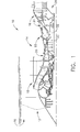
- FIG. 1 is a cross-sectional view of an exemplary gas turbine engine (GTE) 10.
- GTE 10 includes a fan assembly 12, a core gas turbine engine section 14 coupled downstream from fan assembly 12, and a low-pressure turbine 16 coupled downstream from the core gas turbine engine section 14.
- core gas turbine engine section 14 includes a multi-stage booster compressor 18, a high-pressure compressor 20, a combustor 22, and a high-pressure turbine 24.
- GTE 10 also includes an inlet 26 and an exhaust 28.
- low-pressure turbine 16 and booster compressor 18 are coupled together via a first drive shaft 30, and compressor 20 and high-pressure turbine 24 are coupled together via a second drive shaft 32.
- air is drawn into engine inlet 26, and compressed through booster compressor 18 and high pressure compressor 20.
- the compressed air is channeled to combustor 22 where it is mixed with fuel and ignited to produce air flow through high pressure turbine 24 and low pressure turbine 16, and exits through exhaust 28.
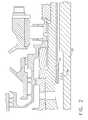
- FIG. 2 is an enlarged cross-sectional view of the gas turbine engine shown in FIG. 1 .
- GTE 10 includes a seal 34 coupled to first shaft 30.
- Seal 34 is separable from shaft 30 and includes at least two segments such that it may be installed or removed on a complete shaft without needing clearance on either end of the shaft. Moreover, being made of at least two segments facilitates installation of seal 34 on a shaft even when the shaft has a greater diameter on both sides of seal 34 installation point, which provides much greater flexibility in where seal 34 is located on a shaft.
- Seal 34 may include, as desired, labyrinth tooth material of the same material, or different material, as/than the shaft 30, respectively. Seal 34 may be coupled to shaft 30 in multiple ways, which are described below.
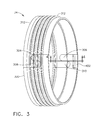
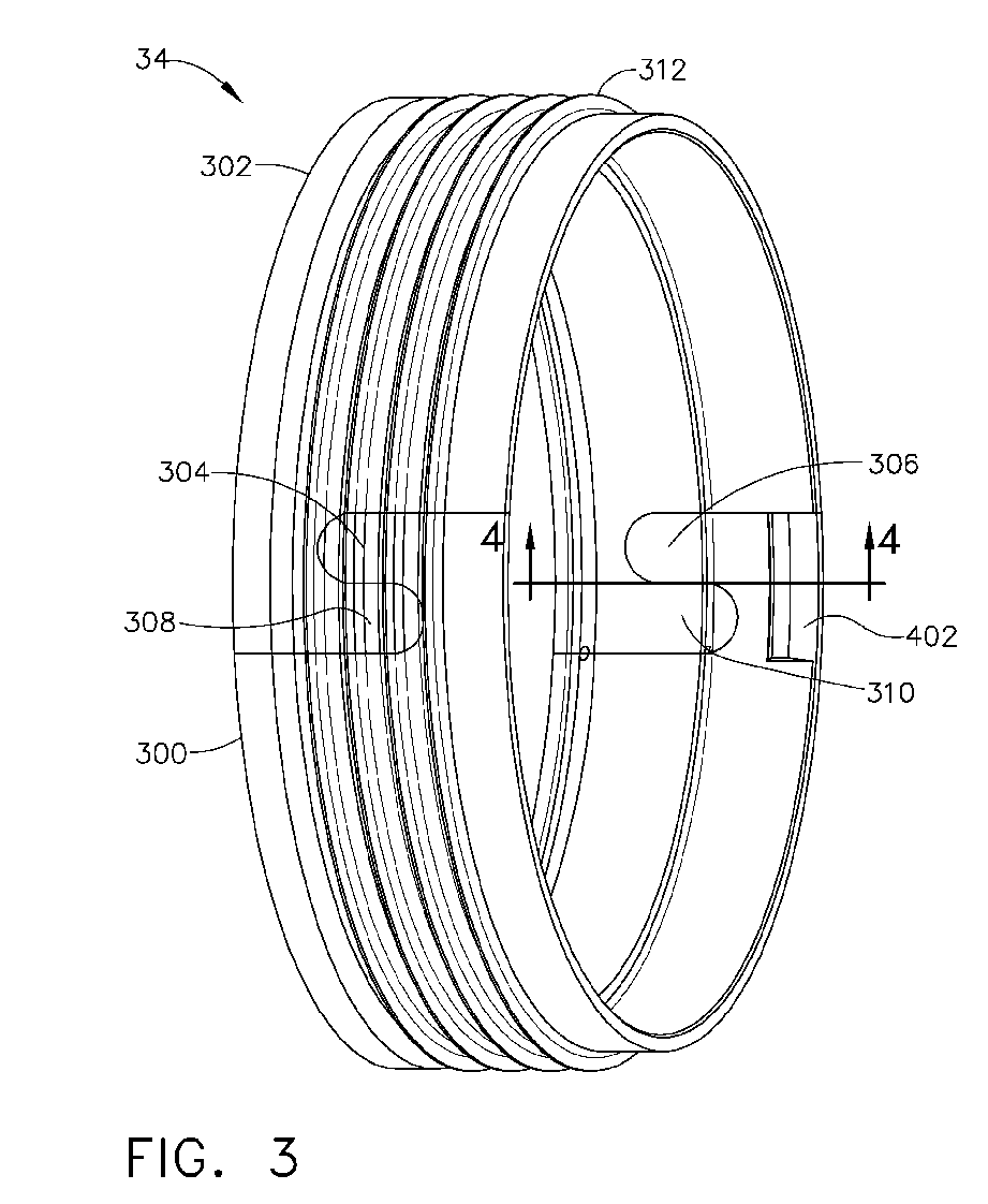
- FIG. 3 is a perspective view of an exemplary seal 34 in accordance with the present invention.
- Seal 34 includes a first half circle-shaped segment 300 and a second half circle-shaped segment 302.
- First segment 300 includes a first end having a connector 304 and a second end having a connector 306.
- Second segment 302 includes a first end having a connector 308 and a second end having a connector 310.
- First segment 300 and second segment 302 assemble by an overlap joint, by joining connectors 304 and 308, and connectors 306 and 310. The overlap joint allows seal 34 to carry a hoop load.
- Segments 300 and 302 each include a plurality of seal teeth 312.
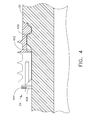
- FIG. 4 is a cross-sectional view of seal 34 (shown in FIG. 3 ) coupled to a shaft taken at line 4-4 in FIG. 3 .
- the shaft is shaft 30 (shown in FIG. 1 ).
- the primary retention for seal 34 is an interference fit between seal 34 and a shoulder 400 of shaft 30.
- First segment 300 includes a shoulder 402 (shown in FIG. 3 ) that enables secondary axial and tangential retention on shaft 30.
- first and second segments 300 and 302 about shaft 30 is accomplished by heating both first and second segments 300 and 302 to a predetermined temperature, sliding first segment 300 in from a side of shaft 30, and sliding second segment 302 axially such that connectors 308 and 310 engage the mating halves of connectors 304 and 306, respectively.
- First and second segments 300 and 302 enable the ring formed by their coupling to carry hoop stress.
- a retaining ring 404 is expanded into a slot 406.
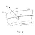
- an alignment pin 500 is placed in an alignment orifice 502 formed between first and second segments 300 and 302 (shown in FIGS. 3 and 4 ). Alignment pin 500 is then trapped by the retaining ring, which is installed last.
- FIG. 6 is a perspective view of an alternative embodiment of seal 34 in accordance with the present invention.
- Seal 34 includes first inner ring segment 600, second inner ring segment 602, first outer ring segment 604, and second outer ring segment 606.
- First and second inner ring segments 600 and 602 are similar to first and second segments 300 and 302, as described in FIGS. 3-5 , less the retaining ring, and are coupled to a shaft in the same manner.
- Seal 34 also includes first outer ring segment 604 and second outer ring segment 606 coupled together about first and second inner ring segments 600 and 602.
- Outer ring segments 604 and 606 each include a plurality of seal teeth 608.
- FIG. 7 is a cross-sectional view of seal 34 on shaft 30 (shown in FIG. 1 ) taken at line 7-7 in FIG. 6 .
- the primary retention of seal 34 is accomplished by an interference fit to shaft 30, and secondary axial retention is accomplished by protrusions 701 on the inner diameter of seal 34 on either side of a shoulder 700 of shaft 30. Secondary tangential retention is provided by a tab 702 which engages with a keyway 704 on shaft 30.
- the four ring segments 600, 602, 604, and 606 are coupled along two 360 degree seams 708 between the segments. Segments 600, 602, 604, and 606 may be coupled by welding and brazing.
- first and second segments 600 and 602 about shaft 30 is accomplished by heating both first and second inner ring segments 600 and 602, sliding first inner ring segment 600 in from the side, and sliding second inner ring segment 602 axially such that connector 610 engages the mating half of connector 612, and another set of connectors (not shown) engage on the other side of seal 34.
- an interference fit is generated between first and second inner ring segments 600 and 602 and shaft 30, enabling segments 600 and 602 to carry hoop stress.
- two 180 degree segments, first outer ring segment 604 and second outer ring segment 606, are coupled to the ring created by first and second inner ring segments 600 and 602, and welded in place.
- the weld joint is formed along the two 360 degree seams between outer ring segments 604 and 606, and inner ring segments 600 and 602.
- Seal teeth 608 are finish machined following assembly and welding of segments 600, 602, 604, and 606 to ensure tooth alignment and tip runout requirements are met.
- FIG. 8 is a perspective view of an alternate embodiment of seal 34 in accordance with the present invention.
- FIG. 9 is a cross-sectional view of separable seal 34 on a shaft taken at line 9-9 in FIG. 8 .
- Seal 34 is comprised of a plurality of identical segments 800.
- seal 34 includes four identical segments 800. Segments 800 are connected to shaft 30 (shown in FIG. 1 ) by a dovetail joint. Segments 800 each include a plurality of seal teeth 802.
- Segments 800 are assembled about shaft 30 (shown in FIG. 1 ) by inserting them through a load slot 804 in shaft 30. Segments 800 are then rotated around load slot 804 until all segments 800 are in place. For each segment 800, a set screw (not shown) is installed through a tapped hole 806 located in each segment 800. The screw engages with a dimple 900 in shaft 30 to provide secondary retention. Each segment 800 has only a dovetail pressure face over the central 50% of its arc length, allowing load slot 804 to be smaller in size.
- the seal assembly described herein enables installation of a separable seal on a shaft where integral teeth and/or a one piece ring are not usable.
- the seal assembly provides a 360 degree ring that can be installed on a completed shaft without needing clearance on either end for installation.
- the assembly provides different connection options depending on the specifications required.
- inventive embodiments are presented by way of example only and that, within the scope of the appended claims and equivalents thereto, inventive embodiments may be practiced otherwise than as specifically described and claimed.
- inventive embodiments of the present disclosure are directed to each individual feature, system, article, material, kit, and/or method described herein.
Landscapes
- Engineering & Computer Science (AREA)
- Mechanical Engineering (AREA)
- General Engineering & Computer Science (AREA)
- Gasket Seals (AREA)
- Turbine Rotor Nozzle Sealing (AREA)
- Sealing Using Fluids, Sealing Without Contact, And Removal Of Oil (AREA)
- Sealing Devices (AREA)
Abstract
A seal assembly for sealing a rotatable shaft (30) in a gas turbine engine (10), wherein the shaft includes sections of greater shaft diameter located both forward and aft of a seal shaft coupling point is provided. The seal assembly includes a first semi-annular segment (300) with a first end, a second end, and a plurality of seal teeth (312), where the first and second ends each include an overlap joint. The seal assembly also includes a second semi-annular segment (302) with a first end, a second end, and a plurality of seal teeth (312), where the first and second ends each include an overlap joint. The first end of the second segment is coupled to the first end of the first segment, and the second end of the second segment is coupled to the second end of the first segment.
Description
- The field of the invention relates generally to gas turbines, and more particularly to methods and a system for a seal assembly for an inter-shaft seal in a gas turbine engine.
- Labyrinth seals are widely used on rotatable shafts to regulate secondary air flows and provide a radial clearance between low speed shafts and high speed shafts in gas turbine engines. Generally, in more detail, the seals include a series of parallel teeth that facilitate regulating a flow past the teeth and capturing any excess oil. The tips of the teeth provide the clearance between the two shafts. Newer generation engines include shafts made of strong, but brittle materials that may not be as tolerant of the rubbing that typical seal teeth endure during engine operation. The rubbing can cause localized micro-cracking in the shaft. Seals made of a single unit that are integral to the shaft may not be allowable in some situations due to material or stress concerns. Additionally, sections of greater shaft diameter located both forward and aft of the seal can prevent implementation of the seal on an unbroken ring of material. Accordingly, a seal that is separable and not subject to the torque load of the shaft, which results in greater flexibility in design at a lower cost for repair and maintenance is desirable.
- In one aspect, a seal assembly for sealing a rotatable shaft in a gas turbine engine, wherein the shaft includes sections of greater shaft diameter located both forward and aft of the seal shaft coupling point is provided. The seal assembly includes a first semi-annular segment with a first end, a second end, and a plurality of seal teeth, where the first and second ends each include an overlap joint. The seal assembly also includes a second semi-annular segment with a first end, a second end, and a plurality of seal teeth, where the first and second ends each include an overlap joint. The first end of the second segment is coupled to the first end of the first segment, and the second end of the second segment is coupled to the second end of the first segment.
-
FIG. 1 is a cross-sectional view of an exemplary gas turbine engine assembly for use in propelling an aircraft. -
FIG. 2 is an enlarged cross-sectional view of the exemplary seal shown inFIG. 1 in relation to the first and second shafts. -
FIG. 3 is a perspective view of an exemplary seal in accordance with the present invention. -
FIG. 4 is a cross-sectional view of the seal on the first shaft taken at line 4-4 inFIG. 3 . -
FIG. 5 is a perspective view of an alignment pin connecting the two segments of the seal shown inFIGS. 3 and4 . -
FIG. 6 is a perspective view of an alternate embodiment of the seal in accordance with the present invention. -
FIG. 7 is a cross-sectional view of the seal on the first shaft taken at line 7-7 inFIG. 6 . -
FIG. 8 is a perspective view of an alternate embodiment of the seal in accordance with the present invention. -
FIG. 9 is a cross-sectional view of the seal on the first shaft taken at line 9-9 inFIG. 8 . - The following detailed description illustrates an inter-shaft seal and a method of assembling the same by way of example and not by way of limitation. The description enables one of ordinary skill in the art to make and use the disclosure, and the description describes several embodiments of the disclosure, including what is presently believed to be the best mode of carrying out the disclosure. The disclosure is described herein as being applied to a preferred embodiment, namely, an inter-shaft seal and a method of assembling the same. However, it is contemplated that this disclosure has general application to shaft seals in a broad range of systems and in a variety of industrial and/or consumer applications.
-
FIG. 1 is a cross-sectional view of an exemplary gas turbine engine (GTE) 10. GTE 10 includes afan assembly 12, a core gasturbine engine section 14 coupled downstream fromfan assembly 12, and a low-pressure turbine 16 coupled downstream from the core gasturbine engine section 14. In the exemplary embodiment, core gasturbine engine section 14 includes amulti-stage booster compressor 18, a high-pressure compressor 20, acombustor 22, and a high-pressure turbine 24. GTE 10 also includes aninlet 26 and anexhaust 28. In the exemplary embodiment, low-pressure turbine 16 andbooster compressor 18 are coupled together via afirst drive shaft 30, andcompressor 20 and high-pressure turbine 24 are coupled together via asecond drive shaft 32. - In operation, air is drawn into
engine inlet 26, and compressed throughbooster compressor 18 andhigh pressure compressor 20. The compressed air is channeled tocombustor 22 where it is mixed with fuel and ignited to produce air flow throughhigh pressure turbine 24 andlow pressure turbine 16, and exits throughexhaust 28. -
FIG. 2 is an enlarged cross-sectional view of the gas turbine engine shown inFIG. 1 . GTE 10 includes aseal 34 coupled tofirst shaft 30.Seal 34 is separable fromshaft 30 and includes at least two segments such that it may be installed or removed on a complete shaft without needing clearance on either end of the shaft. Moreover, being made of at least two segments facilitates installation ofseal 34 on a shaft even when the shaft has a greater diameter on both sides ofseal 34 installation point, which provides much greater flexibility in whereseal 34 is located on a shaft.Seal 34 may include, as desired, labyrinth tooth material of the same material, or different material, as/than theshaft 30, respectively.Seal 34 may be coupled toshaft 30 in multiple ways, which are described below. -
FIG. 3 is a perspective view of anexemplary seal 34 in accordance with the present invention.Seal 34 includes a first half circle-shaped segment 300 and a second half circle-shaped segment 302.First segment 300 includes a first end having aconnector 304 and a second end having aconnector 306.Second segment 302 includes a first end having aconnector 308 and a second end having aconnector 310.First segment 300 andsecond segment 302 assemble by an overlap joint, by joiningconnectors connectors seal 34 to carry a hoop load.Segments seal teeth 312. -
FIG. 4 is a cross-sectional view of seal 34 (shown inFIG. 3 ) coupled to a shaft taken at line 4-4 inFIG. 3 . In the exemplary embodiment, the shaft is shaft 30 (shown inFIG. 1 ). The primary retention forseal 34 is an interference fit betweenseal 34 and ashoulder 400 ofshaft 30.First segment 300 includes a shoulder 402 (shown inFIG. 3 ) that enables secondary axial and tangential retention onshaft 30. - Assembly of first and
second segments shaft 30 is accomplished by heating both first andsecond segments first segment 300 in from a side ofshaft 30, and slidingsecond segment 302 axially such thatconnectors connectors shaft 30, an interference fit is generated between first andsecond segments shaft 30. First andsecond segments second segments retaining ring 404 is expanded into aslot 406. Moreover, with reference toFIG. 5 , analignment pin 500 is placed in analignment orifice 502 formed between first andsecond segments 300 and 302 (shown inFIGS. 3 and4 ).Alignment pin 500 is then trapped by the retaining ring, which is installed last. -
FIG. 6 is a perspective view of an alternative embodiment ofseal 34 in accordance with the present invention.Seal 34 includes firstinner ring segment 600, secondinner ring segment 602, firstouter ring segment 604, and secondouter ring segment 606. First and secondinner ring segments second segments FIGS. 3-5 , less the retaining ring, and are coupled to a shaft in the same manner.Seal 34 also includes firstouter ring segment 604 and secondouter ring segment 606 coupled together about first and secondinner ring segments Outer ring segments seal teeth 608. -
FIG. 7 is a cross-sectional view ofseal 34 on shaft 30 (shown inFIG. 1 ) taken at line 7-7 inFIG. 6 . The primary retention ofseal 34 is accomplished by an interference fit toshaft 30, and secondary axial retention is accomplished byprotrusions 701 on the inner diameter ofseal 34 on either side of ashoulder 700 ofshaft 30. Secondary tangential retention is provided by atab 702 which engages with akeyway 704 onshaft 30. The fourring segments degree seams 708 between the segments.Segments - Assembly of first and
second segments shaft 30 is accomplished by heating both first and secondinner ring segments inner ring segment 600 in from the side, and sliding secondinner ring segment 602 axially such thatconnector 610 engages the mating half ofconnector 612, and another set of connectors (not shown) engage on the other side ofseal 34. When allowed to equalize in temperature withshaft 30, an interference fit is generated between first and secondinner ring segments shaft 30, enablingsegments outer ring segment 604 and secondouter ring segment 606, are coupled to the ring created by first and secondinner ring segments outer ring segments inner ring segments Seal teeth 608 are finish machined following assembly and welding ofsegments -
FIG. 8 is a perspective view of an alternate embodiment ofseal 34 in accordance with the present invention.FIG. 9 is a cross-sectional view ofseparable seal 34 on a shaft taken at line 9-9 inFIG. 8 .Seal 34 is comprised of a plurality ofidentical segments 800. In the exemplary embodiment, seal 34 includes fouridentical segments 800.Segments 800 are connected to shaft 30 (shown inFIG. 1 ) by a dovetail joint.Segments 800 each include a plurality ofseal teeth 802. -
Segments 800 are assembled about shaft 30 (shown inFIG. 1 ) by inserting them through aload slot 804 inshaft 30.Segments 800 are then rotated aroundload slot 804 until allsegments 800 are in place. For eachsegment 800, a set screw (not shown) is installed through a tappedhole 806 located in eachsegment 800. The screw engages with adimple 900 inshaft 30 to provide secondary retention. Eachsegment 800 has only a dovetail pressure face over the central 50% of its arc length, allowingload slot 804 to be smaller in size. - The seal assembly described herein enables installation of a separable seal on a shaft where integral teeth and/or a one piece ring are not usable. The seal assembly provides a 360 degree ring that can be installed on a completed shaft without needing clearance on either end for installation. The assembly provides different connection options depending on the specifications required.
- While multiple inventive embodiments have been described and illustrated herein, those of ordinary skill in the art will readily envision a variety of other means and/or structures for performing the function and/or obtaining the results and/or one or more of the advantages described herein, and each of such variations and/or modifications is deemed to be within the scope of the invent of embodiments described herein. More generally, those skilled in the art will readily appreciate that all parameters, dimensions, materials, and configurations described herein are meant to be exemplary and that the actual parameters, dimensions, materials, and/or configurations will depend upon the specific application or applications for which the inventive teachings is/are used. Those skilled in the art will recognize, or be able to ascertain using no more than routine experimentation, many equivalents to the specific inventive embodiments described herein. It is, therefore, to be understood that the foregoing embodiments are presented by way of example only and that, within the scope of the appended claims and equivalents thereto, inventive embodiments may be practiced otherwise than as specifically described and claimed. Inventive embodiments of the present disclosure are directed to each individual feature, system, article, material, kit, and/or method described herein. In addition, any combination of two or more such features, systems, articles, materials, kits, and/or methods, if such features, systems, articles, materials, kits, and/or methods are not mutually inconsistent, is included within the inventive scope of the present disclosure.
- Examples are used to disclose the embodiments, including the best mode, and also to enable any person skilled in the art to practice the apparatus and/or method, including making and using any devices or systems and performing any incorporated methods. These examples are not intended to be exhaustive or to limit the disclosure to the precise steps and/or forms disclosed, and many modifications and variations are possible in light of the above teaching. Features described herein may be combined in any combination. Steps of a method described herein may be performed in any sequence that is physically possible.
- All definitions, as defined and used herein, should be understood to control over dictionary definitions, definitions in documents incorporated by reference, and/or ordinary meanings of the defined terms. The indefinite articles "a" and "an," as used herein in the specification and in the claims, unless clearly indicated to the contrary, should be understood to mean "at least one." The phrase "and/or," as used herein in the specification and in the claims, should be understood to mean "either or both" of the elements so conjoined, i.e., elements that are conjunctively present in some cases and disjunctively present in other cases.
- It should also be understood that, unless clearly indicated to the contrary, in any methods claimed herein that include more than one step or act, the order of the steps or acts of the method is not necessarily limited to the order in which the steps or acts of the method are recited.
- In the claims, as well as in the specification above, all transitional phrases such as "comprising," "including," "carrying," "having," "containing," "involving," "holding," "composed of," and the like are to be understood to be open-ended, i.e., to mean including but not limited to.
- Various aspects and embodiments of the present invention are defined by the following numbered clauses:
- 1. A seal assembly for sealing a rotatable shaft in a gas turbine engine comprising:
- the rotatable shaft comprising sections of greater shaft diameter located both forward and aft of the seal shaft coupling point, said seal assembly comprising:
- a first semi-annular segment comprising a first end, a second end, and a plurality of seal teeth, said first and second ends each including an overlap joint; and
- a second semi-annular segment comprising a first end, a second end, and a plurality of seal teeth, said first and second ends each including an overlap joint, said first end of said second segment being coupled to said first end of said first segment,
- and said second end of said second segment being coupled to said second end of said first segment.
- 2. The seal assembly of Clause 1, further comprising:
- a seal coupled to a first shaft, the seal being separable from the shaft and including at least two segments;
- the seal being capable of being installed or removed on a complete shaft without a need to provide clearance on either end of the shaft;
- the at least two segments facilitating installation of the seal on the shaft to include shafts having a greater diameter on both sides of a seal installation point, thereby providing a multiplicity of choices for location of the seal with respect to the shaft.
- 3. A seal assembly for sealing a rotatable shaft in a gas turbine engine comprising:
- the shaft comprising sections of greater shaft diameter located both forward and aft of the seal shaft coupling point, said seal assembly comprising:
- a first half circle-shaped segment and a second half circle-shaped segment;
- the first segment including a first end having a connector and a second end having a connector; and,
- the second segment including a first end having a connector and a second end having a connector.
- the shaft comprising sections of greater shaft diameter located both forward and aft of the seal shaft coupling point, said seal assembly comprising:
- 4. The seal assembly of Clause 3, further comprising:
- the first segment and the second segment being assembled by an overlap joint, wherein mating connectors and, are joined with co-mating connectors; and,
- the overlap joint thereby allowing the seal to carry a hoop load.
- 5. The seal assembly of any preceding Clause, further comprising segments, each segment including a plurality of seal teeth.
- 6. The seal assembly of any preceding Clause, further comprising a primary retention for the seal being an interference fit between seal and a shoulder of shaft wherein the first segment includes a shoulder that enables secondary axial and tangential retention on the shaft.
- 7. The seal assembly of any preceding Clause, further comprising the assembly of the first and second segments and about the shaft being accomplished by heating both the first and the second segments to a predetermined temperature, sliding first segment in from a side of shaft, and sliding second segment axially such that the connectors of one segment engage the mating halves of connectors on the other segment, respectively.
- 8. The seal assembly of any preceding Clause, further comprising allowing temperature to equalize within the shaft thereby providing an interference fit being generated between first and second segments and shaft;
the first and second segments enabling the ring formed by their coupling to carry hoop stress;
the first and second segments being secured together by a retaining ring that is expanded into a slot;
an alignment pin being placed in an alignment orifice that is disposed between the first and second segments; and,
the retaining ring being installed last, thereby securing the alignment pin. - 9. A seal assembly for sealing a rotatable shaft in a gas turbine engine comprising:
- the shaft comprising sections of greater shaft diameter located both forward and aft of the seal shaft coupling point; and,
- said seal assembly comprising a first inner ring segment, a second inner ring segment, a first outer ring segment, and a second outer ring segment.
- 10. The seal assembly of any preceding Clause, further comprising the first outer ring segment and the second outer ring segment coupled together about first and second inner ring segments and wherein the outer ring segments and each include a plurality of seal teeth.
- 11. The seal assembly of any preceding Clause, further comprising the primary retention of seal being accomplished by an interference fit to shaft, and secondary axial retention being accomplished by protrusions on the inner diameter of seal on either side of a shoulder of shaft.
- 12. The seal assembly of any preceding Clause, further comprising that secondary tangential retention is provided by a tab which engages with a keyway on the shaft;
the four ring segments are coupled along two 360 degree seams between the segments; and,
the segments being coupled by a securing method chosen from the group welding, brazing. - 13. The seal assembly of any preceding Clause, further comprising that an initial assembly of first and second segments and about shaft is accomplished by:
- heating both first and second inner ring segments;
- sliding first inner ring segment in from the side, and sliding second inner ring segment axially such that connector engages the mating half of connector, while a corresponding set of connectors engages in a similar fashion on the other side of the seal; and,
- when allowed to equalize in temperature with shaft, an interference fit is generated between first and second inner ring segments and shaft, enabling segments to carry hoop stress.
- 14. The seal assembly of any preceding Clause, further comprising that following the initial assembly steps of claim 13:
- two 180 degree segments being the first outer ring segment and the second outer ring segment, are coupled to the ring created by first and second inner ring segment;
- the 180 degree segments being welded in place wherein the weld joint is formed along two 360 degree seams between the outer ring segments, and the inner ring segments; and,
- seal teeth are finish machined following assembly and welding of segments thereby ensuring that tooth alignment and tip runout requirements are met.
- 15. A seal assembly for sealing a rotatable shaft in a gas turbine engine comprising:
- the shaft comprising sections of greater shaft diameter located both forward and aft of the seal shaft coupling point; and,
- said seal assembly comprising a plurality of identical segments.
- 16. The seal assembly of any preceding Clause, further comprising the plurality being four identical segments connected to the shaft by a dovetail joint and wherein each segment includes a plurality of seal teeth.
- 17. The seal assembly of any preceding Clause, further comprising that assembly of segments about the shaft is accomplished by:
- inserting the segments through a load slot formed in the shaft; and,
- rotating the segments around the load slot, repeating until all segments are in place.
- 18. The seal assembly of any preceding Clause, further comprising installing a set screw through a tapped hole located in each segment.
- 19. The seal assembly of any preceding Clause, wherein the set screw engages with a dimple in shaft thereby providing secondary retention.
- 20. The seal assembly of any preceding Clause, wherein each segment has formed upon it a dovetail pressure face over a central 50% of its arc length, thereby allowing a corresponding reduction in the size of the load slot.
Claims (15)
- A seal assembly for sealing a rotatable shaft (30) in a gas turbine engine (10) comprising:the rotatable shaft (30) comprising sections of greater shaft diameter located both forward and aft of a seal shaft coupling point, said seal assembly comprising:a first semi-annular segment (300) comprising a first end, a second end, and a plurality of seal teeth (312), said first and second ends each including an overlap joint (304,306); anda second semi-annular segment (302) comprising a first end, a second end, and a plurality of seal teeth (312), said first and second ends each including an overlap joint (308,310), said first end of said second segment (302) being coupled to said first end of said first segment (300), and said second end of said second segment (302) being coupled to said second end of said first segment (300).
- The seal assembly of Claim 1, further comprising:a seal (34) coupled to a first shaft (30), the seal being separable from the shaft and including at least two segments (300,302);the seal being capable of being installed or removed on the shaft without a need to provide clearance on either end of the shaft;the at least two segments (300,302) facilitating installation of the seal on the shaft to include shafts having a greater diameter on both sides of a seal installation point, thereby providing a multiplicity of choices for location of the seal with respect to the shaft.
- A seal assembly for sealing a rotatable shaft (30) in a gas turbine engine (10) comprising:the shaft (30) comprising sections of greater shaft diameter located both forward and aft of a seal shaft coupling point, said seal assembly (34) comprising:a first half circle-shaped segment (300) and a second half circle-shaped segment (302);the first segment (300) including a first end having a connector (304) and a second end having a connector (306); and,the second segment (302) including a first end having a connector (308) and a second end having a connector (310).
- The seal assembly of claim 3, further comprising:the first segment (300) and the second segment (302) being assembled by an overlap joint, wherein mating connectors (304,306) are joined with co-mating connectors (308,310); and,the overlap joint thereby allowing the seal to carry a hoop load.
- The seal assembly of claim 4, each segment including a plurality of seal teeth (312).
- The seal assembly of claim 5, further comprising a primary retention for the seal (34) being an interference fit between the seal (34) and a shoulder (400) of the shaft (30) wherein the first segment (300) includes a shoulder (402) that enables secondary axial and tangential retention on the shaft (30).
- The seal assembly of claim 6, further comprising the assembly of the first and second segments (300,302) and about the shaft (30) being accomplished by heating both the first and the second segments to a predetermined temperature, sliding the first segment (300) in from a side of shaft (30), and sliding the second segment (302) axially such that the connectors (304,306) of the first segment (300) engage the mating halves of connectors (308,310) on the second segment (302), respectively.
- A seal assembly for sealing a rotatable shaft (30) in a gas turbine engine (10) comprising:the shaft (30) comprising sections of greater shaft diameter located both forward and aft of a seal shaft coupling point; and,said seal assembly comprising a first inner ring segment (600), a second inner ring segment (602), a first outer ring segment (604), and a second outer ring segment (606).
- The seal assembly of claim 8, further comprising the first outer ring segment (604) and the second outer ring segment (606) coupled together about the first and second inner ring segments (600,602) and wherein the outer ring segments (604,606) each include a plurality of seal teeth (608).
- The seal assembly of claim 9, further comprising the primary retention of seal (34) being accomplished by an interference fit to the shaft (30), and secondary axial retention being accomplished by protrusions (701) on the inner diameter of the seal on either side of a shoulder (700) of the shaft.
- The seal assembly of claim 10, further comprising the secondary tangential retention being provided by a tab (702) which engages with a keyway (704) on the shaft (30);
the first inner, second inner, first outer and second outer ring segments (600,602,604,606) being coupled along two 360 degree seams between the segments; and,
the segments being coupled by a securing method chosen from the group consisting of welding and brazing. - A seal assembly for sealing a rotatable shaft (30) in a gas turbine engine (10) comprising:the shaft (30) comprising sections of greater shaft diameter located both forward and aft of a seal shaft coupling point; and,said seal assembly comprising a plurality of identical segments (800).
- The seal assembly of claim 12, further comprising the plurality of identical segments (800) being four identical segments (800) connected to the shaft (30) by a dovetail joint and wherein each segment includes a plurality of seal teeth (802).
- The seal assembly of either of claim 12 or 13, further comprising a set screw installed through a tapped hole (806) located in each segment (800).
- The seal assembly of claim 14, wherein the set screw engages with a dimple (900) in shaft (30) thereby providing secondary retention.
Applications Claiming Priority (2)
| Application Number | Priority Date | Filing Date | Title |
|---|---|---|---|
| US201261639403P | 2012-04-27 | 2012-04-27 | |
| US13/771,135 US20130287551A1 (en) | 2012-04-27 | 2013-02-20 | Separable seal assembly for a gas turbine engine |
Publications (1)
| Publication Number | Publication Date |
|---|---|
| EP2657456A2 true EP2657456A2 (en) | 2013-10-30 |
Family
ID=48182815
Family Applications (1)
| Application Number | Title | Priority Date | Filing Date |
|---|---|---|---|
| EP13165263.8A Withdrawn EP2657456A2 (en) | 2012-04-27 | 2013-04-25 | Separable inter shaft seal assembly for a gas turbine engine |
Country Status (6)
| Country | Link |
|---|---|
| US (1) | US20130287551A1 (en) |
| EP (1) | EP2657456A2 (en) |
| JP (1) | JP2013231431A (en) |
| CN (1) | CN103375190A (en) |
| BR (1) | BR102013010230A2 (en) |
| CA (1) | CA2813519A1 (en) |
Cited By (1)
| Publication number | Priority date | Publication date | Assignee | Title |
|---|---|---|---|---|
| EP3124754A1 (en) * | 2015-07-29 | 2017-02-01 | General Electric Company | Near flow path seal for a turbomachine |
Families Citing this family (4)
| Publication number | Priority date | Publication date | Assignee | Title |
|---|---|---|---|---|
| CN110131049B (en) * | 2018-02-09 | 2020-11-03 | 中国航发商用航空发动机有限责任公司 | Sealing ring for engine rotor |
| FR3093541B1 (en) * | 2019-03-08 | 2021-07-16 | Safran Aircraft Engines | Double rotor aircraft gas turbine |
| CN111089000B (en) * | 2019-12-05 | 2024-11-08 | 西安交通大学 | An adaptive high-durability floating seal structure suitable for extreme conditions |
| CN111764969B (en) * | 2020-07-27 | 2022-08-30 | 中国航发沈阳发动机研究所 | Aeroengine sealing structure |
Family Cites Families (6)
| Publication number | Priority date | Publication date | Assignee | Title |
|---|---|---|---|---|
| DE3600124A1 (en) * | 1986-01-04 | 1987-07-16 | Fortuna Werke Maschf Ag | BLOWERS FOR CIRCUITING LARGE QUANTITIES OF GAS, IN PARTICULAR FOR HIGH-PERFORMANCE LASERS |
| US5980204A (en) * | 1998-04-28 | 1999-11-09 | General Electric Co. | Method of establishing hook diameters on diaphragm packing ring dovetails |
| IT1318065B1 (en) * | 2000-06-29 | 2003-07-21 | Nuovo Pignone Spa | SEALING AND PRESSURIZATION SYSTEM FOR THE BEARING OF A GAS TURBINE |
| US7488153B2 (en) * | 2002-07-01 | 2009-02-10 | Alstom Technology Ltd. | Steam turbine |
| US7025559B2 (en) * | 2004-06-04 | 2006-04-11 | General Electric Company | Methods and systems for operating rotary machines |
| US8740563B2 (en) * | 2010-11-22 | 2014-06-03 | General Electric Company | Sealing assembly for use in turbomachines and methods of assembling same |
-
2013
- 2013-02-20 US US13/771,135 patent/US20130287551A1/en not_active Abandoned
- 2013-04-18 CA CA2813519A patent/CA2813519A1/en not_active Abandoned
- 2013-04-24 JP JP2013090844A patent/JP2013231431A/en active Pending
- 2013-04-25 EP EP13165263.8A patent/EP2657456A2/en not_active Withdrawn
- 2013-04-26 BR BR102013010230A patent/BR102013010230A2/en not_active Application Discontinuation
- 2013-04-26 CN CN2013101491082A patent/CN103375190A/en active Pending
Non-Patent Citations (1)
| Title |
|---|
| None |
Cited By (1)
| Publication number | Priority date | Publication date | Assignee | Title |
|---|---|---|---|---|
| EP3124754A1 (en) * | 2015-07-29 | 2017-02-01 | General Electric Company | Near flow path seal for a turbomachine |
Also Published As
| Publication number | Publication date |
|---|---|
| BR102013010230A2 (en) | 2017-05-09 |
| JP2013231431A (en) | 2013-11-14 |
| CA2813519A1 (en) | 2013-10-27 |
| CN103375190A (en) | 2013-10-30 |
| US20130287551A1 (en) | 2013-10-31 |
Similar Documents
| Publication | Publication Date | Title |
|---|---|---|
| US9498850B2 (en) | Structural case for aircraft gas turbine engine | |
| US10443615B2 (en) | Alignment of flanged components | |
| US9175566B2 (en) | Gas turbine engine preswirler with angled holes | |
| EP2657456A2 (en) | Separable inter shaft seal assembly for a gas turbine engine | |
| JP6870964B2 (en) | CMC thermal clamp | |
| CN203809239U (en) | Compressor rectification segment and as turbine | |
| WO2014159635A1 (en) | Turbine blade with a pin seal slot | |
| WO2014159366A1 (en) | Turbine blade pin seal | |
| EP2615374A2 (en) | Combustor and method for reducing thermal stresses in a combustor | |
| US9341194B2 (en) | Gas turbine engine compressor with a biased inner ring | |
| EP3249164B1 (en) | Side seal with reduced corner leakage | |
| US9470092B2 (en) | System and method for attaching a rotating blade in a turbine | |
| WO2014123950A2 (en) | Forged fuel injector stem | |
| US20160115874A1 (en) | Liner grommet assembly | |
| US10378383B2 (en) | Alignment apparatus for coupling diaphragms of turbines | |
| US10450882B2 (en) | Anti-rotation shim seal | |
| GB2547273A (en) | Stator vane | |
| US20240318562A1 (en) | Turbine tip shroud removal feature | |
| US11927101B1 (en) | Machine ring multi-slope tipshoe/tip shroud/outer air shroud | |
| US12146422B2 (en) | Gas turbine engine including a rotating blade assembly | |
| US11112037B2 (en) | Hose connection system | |
| US20130323074A1 (en) | Friction welded turbine disk and shaft | |
| US20210033283A1 (en) | Diffuser case heatshields for gas turbine engines | |
| EP3163015A1 (en) | Power nozzle repair with cooling hardware installed |
Legal Events
| Date | Code | Title | Description |
|---|---|---|---|
| PUAI | Public reference made under article 153(3) epc to a published international application that has entered the european phase |
Free format text: ORIGINAL CODE: 0009012 |
|
| AK | Designated contracting states |
Kind code of ref document: A2 Designated state(s): AL AT BE BG CH CY CZ DE DK EE ES FI FR GB GR HR HU IE IS IT LI LT LU LV MC MK MT NL NO PL PT RO RS SE SI SK SM TR |
|
| AX | Request for extension of the european patent |
Extension state: BA ME |
|
| STAA | Information on the status of an ep patent application or granted ep patent |
Free format text: STATUS: THE APPLICATION IS DEEMED TO BE WITHDRAWN |
|
| 18D | Application deemed to be withdrawn |
Effective date: 20161101 |