EP2657418A1 - Noise reduction unit for vacuum suction drains - Google Patents
Noise reduction unit for vacuum suction drains Download PDFInfo
- Publication number
- EP2657418A1 EP2657418A1 EP12165713.4A EP12165713A EP2657418A1 EP 2657418 A1 EP2657418 A1 EP 2657418A1 EP 12165713 A EP12165713 A EP 12165713A EP 2657418 A1 EP2657418 A1 EP 2657418A1
- Authority
- EP
- European Patent Office
- Prior art keywords
- noise reduction
- reduction unit
- diameter
- vacuum suction
- drain
- Prior art date
- Legal status (The legal status is an assumption and is not a legal conclusion. Google has not performed a legal analysis and makes no representation as to the accuracy of the status listed.)
- Granted
Links
Images



Classifications
-
- B—PERFORMING OPERATIONS; TRANSPORTING
- B65—CONVEYING; PACKING; STORING; HANDLING THIN OR FILAMENTARY MATERIAL
- B65G—TRANSPORT OR STORAGE DEVICES, e.g. CONVEYORS FOR LOADING OR TIPPING, SHOP CONVEYOR SYSTEMS OR PNEUMATIC TUBE CONVEYORS
- B65G53/00—Conveying materials in bulk through troughs, pipes or tubes by floating the materials or by flow of gas, liquid or foam
- B65G53/34—Details
- B65G53/52—Adaptations of pipes or tubes
- B65G53/54—Flexible pipes or tubes
-
- B—PERFORMING OPERATIONS; TRANSPORTING
- B64—AIRCRAFT; AVIATION; COSMONAUTICS
- B64D—EQUIPMENT FOR FITTING IN OR TO AIRCRAFT; FLIGHT SUITS; PARACHUTES; ARRANGEMENT OR MOUNTING OF POWER PLANTS OR PROPULSION TRANSMISSIONS IN AIRCRAFT
- B64D11/00—Passenger or crew accommodation; Flight-deck installations not otherwise provided for
- B64D11/02—Toilet fittings
-
- E—FIXED CONSTRUCTIONS
- E03—WATER SUPPLY; SEWERAGE
- E03F—SEWERS; CESSPOOLS
- E03F1/00—Methods, systems, or installations for draining-off sewage or storm water
- E03F1/006—Pneumatic sewage disposal systems; accessories specially adapted therefore
Definitions
- the present invention relates to a noise reduction unit for inserting in a vacuum suction drain, a vacuum system and an aircraft with a vacuum system.
- vacuum system and "vacuum suction drain” refers to special pneumatic conveyors.
- transportation takes place in that a pressure difference is applied to the material to be conveyed, i.e. the material to be conveyed is entrained in the fluid flow generated as a result of the pressure difference, wherein generally speaking air is used as the transport medium.
- vacuum systems are used for the transportation of waste from the cabin, for example from toilets or galleys, to a central waste collecting tank.
- the material to be conveyed is conveyed to the waste collecting tank by way of a pipeline network, i.e. vacuum suction drains.
- Negative pressure in the waste collecting tank in relation to the cabin pressure provides the required pressure difference.
- the pressure difference between the cabin and the environment is used directly to generate the negative pressure for pneumatic conveyance.
- this pressure difference is insufficient, e.g. on the tarmac or at low altitudes, the required pressure difference is generated by a compressor.
- a noise reduction unit for inserting in a vacuum suction drain is adapted to be flown through by a material to be conveyed through the vacuum suction drain, wherein the noise reduction unit comprises an inlet section with a first diameter, a middle section with a second diameter and an outlet section with a third diameter, wherein the middle section is arranged between the inlet section and the outlet section, wherein the middle section is adapted to affect a flow velocity reduction of the material to be conveyed from the inlet section to the outlet section and wherein the second diameter differs from both the first diameter and the third diameter.
- the vacuum suction drain may be a pipe of a vacuum suction system, which vacuum suction system may be adapted for conveying material from a suction point to a collection point, for example from a first container like a wash basin or toilet bowl, i.e. the suction point, to a second container like a waste collection container, i.e. the second container.
- the material to be conveyed may in particular be a multiphase material, i.e. consisting of liquid phase material and solid phase material.
- the noise reduction unit may be adapted for modular insertion in the vacuum suction drain such that the material to be conveyed flows through the vacuum suction drain and as part of this flowing or suction process flows through the noise reduction system.
- the noise reduction unit may be inserted additional in an existing system of vacuum suction drains as well as in a mounting process prior to an initial operation of the vacuum suction drain.
- the inlet section and the outlet section of the vacuum suction unit connect the noise reduction unit to the vacuum suction drain, wherein the material to be conveyed flows through the noise reduction unit in a direction from the inlet section via the middle section to the outlet section.
- the middle section is adapted to affect a flow velocity reduction of the material to be conveyed.
- the middle section may also reduce the flow velocity of the air which serves as the transportation medium for the material to be conveyed.
- the suction of the material to be conveyed in vacuum systems occurs because of a pressure difference between the suction point and the waste collection container.
- this pressure difference decreases gradually as air is soaked into the waste collection container.
- the initial pressure difference has to be high enough such that the material to be conveyed passes the whole length of the vacuum suction drain.
- the high pressure difference when starting the conveying process causes an unpleasant and inconvenient noise comparable to a burst noise or a bang. Reducing the initial pressure difference is not an alternative, as then there is a danger that the material to be conveyed does not pass the whole length of the vacuum suction drain.
- the noise reduction unit as described above and hereinafter reduces the velocity of the material to be conveyed directly when starting the suction process.
- the suction pressure will be sustained for a longer time, as the passed air volume and material to be conveyed volume per unit of time will be decreased.
- the initial conveying velocity will be reduced (which also reduces the generated noise during the suction process), such that the pressure difference will be sustained for a longer time instead of having a high initial conveying velocity which results in a high initial noise as usual by now.
- the noise reduction unit as described above and hereinafter may be used in particular in vacuum suction systems like vacuum toilets.
- the second diameter differs from the first diameter such that the flow of the material to be conveyed through the vacuum suction drain causes turbulences in the noise reduction unit and/or in the vacuum suction drain, wherein the turbulences reduce the effective flow cross-section of the vacuum suction drain such that the flow velocity of the material to be conveyed is reduced.
- the second diameter may be greater than the first diameter such that the turbulences occur at the transition section from the first diameter of the inlet section to the second diameter of the middle section.
- These turbulences will increasingly arise with increased velocity of the conveyed material through the vacuum suction drain and the noise reduction unit.
- the velocity of the material to be conveyed and of the air used for conveying the material will be reduced in the initial phase of the suction process and the noise which arises in conjunction with the conveying velocity will be reduced.
- the second diameter is greater than the first diameter and the enlargement of the second diameter with respect to the first diameter is adapted to cause the turbulences in the flow of the material to be conveyed.
- the transition from the inlet section with the first diameter to the middle section with the second diameter may be graded, stepped or rounded as described below in more detail.
- the transition may be designed depending on the material to be conveyed and in particular the proportion of transporting air, liquid or fluid phase material and solid material.
- the second diameter of the middle section is greater than the first diameter of the first section, which first diameter corresponds to the diameter of the vacuum suction drain connected to the inlet section, there is no danger that material passing the vacuum suction drain may cause blockage or clogging in the noise reduction unit.
- the second diameter is less than the first diameter and the reduction of the second diameter with respect to the first diameter is adapted to reduce the flow velocity of the material to be conveyed.
- the cross-section of the noise reduction unit is reduced such that in particular a flow velocity of the transportation air in the initial phase of the conveying process is reduced which may also reduce the noise when starting the suction process and the noise of the suction process itself.
- the middle section comprises a flexible hose, wherein the flexible hose is arranged between the inlet section and the outlet section, wherein the flexible hose comprises a constriction, which corresponds to the second diameter.
- the flexible hose is flown through by the material to be conveyed during the suction process.
- the flexible hose comprises a wall which is adapted to stretch or expand in a direction orthogonal to the flow direction, i.e. in a radial direction of the hose.
- two opposite points of the wall of the flexible hose are moving towards each other and away from each other when the flexible hose expands or contracts, respectively.
- the flexible hose In an unloaded state of the vacuum suction drain and the noise reduction unit, i.e. when no material or just transportation air flows through the noise reduction unit, the flexible hose is in the contracted state such that the cross-section of the middle section, that is the flexible hose, is reduced and the flow velocity of the transportation air is reduced.
- the material to be conveyed passes the flexible hose it will expand or stretch such that solid phase material may pass the flexible hose without blocking or clogging it.
- this structure or design of the noise reduction unit will reduce the velocity of the transport air used for transporting the material to be conveyed without reducing the initial pressure difference between the suction point and the collecting container such that the pressure difference ensures that the material to be conveyed will pass the whole length of the vacuum suction drain and yet the initial suction noise will be reduced.
- the flexible hose and/or the middle section as described above and hereinafter may comprise an anti-adhesive layer on a part of an inner surface or the entire inner surface, that is the surface of the inlet section, middle section and/or the outlet section towards a central axis of the noise reduction unit.
- the anti-adhesive layer may comprise Teflon or a material comprising Sol-gel, for example.
- the flexible hose comprises a material tension, which material tension results in a constriction of the flexible hose, i.e. the constriction of the flexible hose is a result of a material tension of the flexible hose.
- the flexible hose may comprise an elastically reversible material which is adapted to keep the flexible hose in the contracted state in its original position.
- solid phase material passes the flexible hose, it will expand from its original position such that the second diameter enlarges and the solid phase material is able to pass the flexible hose.
- the noise reduction unit as described above and hereinafter comprises a pressurization element, which is adapted to cause the constriction of the flexible hose.
- the pressurization element may be arranged to support or replace the material tension of the flexible hose of the middle section.
- the pressurization element may be a circumferential element arranged at the middle section of the noise reduction unit and adapted to press the wall of the flexible hose towards the central axis of the noise reduction unit.
- the pressurization element comprises a gas volume which is adapted to press the wall of the flexible hose towards the central axis of the noise reduction unit.
- the pressurization element is adapted to apply a pressure by means of the gas to the flexible hose, such that the flexible hose is pressed towards the central axis of the noise reduction unit in order to reduce the cross-section of the middle section.
- the pressurization element may comprise an elastic cushion, a liquid or a foam which is adapted to keep the flexible hose in an unloaded state of the vacuum suction drain in its original shape, i.e. to keep the flexible hose constricted, but allows an enlargement of the flexible hose when being passed by solid phase material.
- the gas pressure of the gas volume is controllable, wherein the controlled gas pressure is adapted to vary the second diameter, i.e. the extent of the flexible hose, wherein an increased gas pressure causes a greater constriction of the flexible hose such that the second diameter is reduced.
- the gas pressure may be controlled in order to increase or decrease such that the gas volume increases or decreases, respectively.
- the flexible hose Corresponding to the varied gas pressure and the according gas volume the flexible hose will become stretched or released, wherein the second diameter gets smaller or larger when the gas volume increases and decreases, respectively.
- a reduced second diameter reduces the cross-section of the flexible hose such that a flow velocity of the transportation air and the material to be conveyed is reduced.
- the flexible hose and the gas volume allow an expansion of the second diameter, in particular when being passed by solid phase material.
- the gas pressure may be controlled by a control loop or control system, wherein the noise originated in conveying material through the vacuum suction drain may be the control variable.
- the noise may be detected by a microphone or any other sensor suitable for detecting noise or a noise level.
- the control loop may increase the gas pressure (that is: reduce the second diameter, which results in a reduction of the flow velocity of the material to be conveyed) when the noise level exceeds a given threshold value.
- control variables like the weight of the material to be conveyed or the composition of the multiphase material.
- the gas pressure may be increased in case there are no solid phase elements in the material to be conveyed such that the cross-section of the flexible hose or the middle section in general may be smaller and the flow velocity is reduced.
- the gas pressure may vary during the transportation of the material to be conveyed or may be constant for the time period of a single transportation process, i.e. the gas pressure may be determined prior to each single transportation process, wherein the detected control variable during the previous transportation process determines the gas pressure of the following transportation process.
- the pressurization element comprises an elastically reversible element which is adapted to press the wall of the flexible hose towards the central axis of the noise reduction unit.
- the elastically reversible element may be a foam like foamed plastic or foamed material in general.
- the foam may be adapted to bring the flexible hose in its constricted position such that the second diameter is being reduced.
- the second diameter is able to vary in case solid phase material passes the middle section and a blockage or clogging is avoided.
- the elastically reversible element may be used as an alternative or additional to the pressurized gas volume.
- the gas volume may intrude the hollow spaces or cavities of the foam.
- the noise reduction unit as described above and hereinafter comprises an elastic membrane which extends in a plane orthogonal to the flow direction and comprises an opening for being flown through by the material to be conveyed, wherein the elastic membrane is adapted to extend when being flown through by the material to be conveyed, wherein the opening of the membrane is adapted to reduce the effective cross-section of the noise reduction unit such that a flow velocity of the material to be conveyed is reduced.
- the membrane In an unloaded state of the noise reduction unit the membrane extends towards the central axis of the noise reduction unit.
- the opening of the membrane represents the minimum cross-section of the noise reduction unit.
- the membrane may be arranged in the inlet section, in the middle section or in the outlet section and may be combined with any of the means for reducing the flow velocity of the material to be conveyed described above and hereinafter.
- a vacuum suction system which comprises a first vacuum suction point, a second vacuum suction point, a waste collecting container, a first drain for connecting the first vacuum suction point to the waste collecting container, a second drain for connecting the second vacuum suction point to the waste collecting container and a first noise reduction unit, wherein the first vacuum suction point is arranged at a first distance to the waste collecting container and the second vacuum suction point is arranged at a second distance to the waste collecting container and wherein the first noise reduction unit is arranged in the first drain to adapt a first flow velocity in the first drain to a second flow velocity in the second drain.
- the flow velocity of material to be conveyed in a vacuum suction drain depends on the pressure difference between a suction point and a collection point.
- the pressure difference further depends on the length of the drains as the air capacity or the air volume of the drains have an influence to the pressure difference between the collection point and every single suction point.
- the pressure difference has to be adapted in order to ensure that the material to be conveyed passed the longest drain. This may lead to the effect that the pressure difference is too high for shorter drains which results in a higher noise level in the vicinity of suction points arranged close to the collection point.
- the vacuum suction system as described above and hereinafter may avoid the different noise level generated by suction points connected to the waste collecting container by means of drains with different lengths as a noise reduction unit in a first drain is adapted to adapt the flow velocity of the material to be conveyed through the first drain.
- the noise reduction unit may be arranged in the shorter one of the first drain and the second drain, such that the flow velocity of the material to be conveyed through the shorter drain is reduced.
- the vacuum suction system as described above and hereinafter may in particular reduce the noise level produced by vacuum suction points close to the waste collecting container.
- the vacuum suction system is adapted to reduce the flow velocity in short drains, wherein the pressure difference provided by the system is specified to ensure a transportation process or vacuum suction process with respect to the drains having the maximum length.
- the vacuum suction system comprises a second noise reduction unit which is arranged in the second drain to adapt a second flow velocity in the second drain.
- the flow velocity in the first drain and the flow velocity in the second drain may be adapted independent from each other and independent from the initial pressure difference between each of the suction points and the waste collecting container.
- the first noise reduction unit and the second noise reduction unit are the first noise reduction unit and the second noise reduction unit a noise reduction unit as described above and hereinafter.
- the vacuum suction system may comprise any noise reduction unit for reducing the flow velocity of the transportation air and the material to be conveyed in one drain or a multitude of drains or a noise reduction unit as described in more detail above and hereinafter.
- an aircraft with a vacuum suction system as described above and hereinafter wherein the first vacuum suction point and the second vacuum suction point are one element of the group consisting of a vacuum toilet system, a waste water basin and a vacuum ventilation system.
- the vacuum suction system may of course be used in other means of transport as land vehicles and water vehicles, for example in buses, trains and ships.
- Fig. 1 illustrates a noise reduction unit 100 with an inlet section 102, a middle section 103 and an outlet section 104.
- the inlet section comprises a first connector 122 and the outlet section comprises a second connector 124, each for connecting the noise reduction unit into a vacuum suction drain (not shown).
- a noise insulation element 140 surrounds or encloses the noise reduction unit circumferential.
- the inlet section comprises a first damper 132 and the outlet section comprises a second damper 134.
- the inlet section 102 has a first diameter 112
- the middle section 103 has a second diameter 113
- the outlet section 104 has a third diameter 114.
- the noise reduction unit 100 is adapted to be flown through by material to be conveyed in the direction of the arrow 150, i.e. from the inlet section via the middle section to the outlet section.
- the second diameter 113 of the middle section 103 is larger than the first diameter 112 of the inlet section 102.
- the extension of the diameter of the noise reduction unit from the inlet section to the middle section will cause turbulences 155 which may lower or reduce the kinetic energy of the transportation air and the material to be conveyed.
- This may in particular be used in connection with short vacuum suction drains (i.e. drains connecting a suction point to the waste collecting container, wherein the suction point is close to the waste collecting container) in which a reduction of the kinetic energy will not lead to an insufficient flow velocity.
- the transition from the first diameter to the second diameter may be constructed in form of a stage or a terrace, as shown by the dashed line 105A. Furthermore, this transition may be shaped as a rounded transition, in particular concave shaped as shown by the reference sign 105B or convex shaped.
- the turbulences 155 may result in vibrations of the noise reduction unit with an oscillation direction parallel and antiparallel to the flow direction 150.
- the first damper 132 and the second damper 134 are adapted to absorb and damp the vibrations.
- the first damper and the second damper may be adapted as part of the inlet section and the outlet section, respectively or for interconnecting the inlet section and the outlet section with the vacuum suction drain.
- the first damper and the second damper may be an elastic seal or gasket which is adapted to absorb vibrations.
- the third diameter may be identical to the first diameter or larger than the first diameter such that solid phase material may pass the outlet section without clogging the noise reduction unit.
- Fig. 2 schematically shows a sectional view of a noise damper, wherein the effect of the turbulences 155 is pointed out.
- the arrows 150 indicate the flow direction of the material to be conveyed.
- the transition point from the inlet section 102 to the middle section 103 i.e. from the first diameter to the second diameter, which second diameter is larger than the first diameter and thus causes turbulences 155.
- the turbulences 155 rising at the transition point from the inlet section to the middle section may reduce the effective cross-section of the noise reduction unit, which is indicated by the effective diameter 115 between the turbulences 155.
- the effective diameter 115 will reduce the kinetic energy of the material flow even thought the second diameter 113 of the middle section 104 is larger than the first diameter 112.
- the embodiment of the noise reduction unit 100 illustrated in Figs. 1 and 2 lowers the flow velocity of the material to be conveyed due to the turbulences rising at the broadening section at the transition from the inlet section to the middle section. Even though creating a resistance against the material flow, solid phase material may pass the noise reduction unit without clogging it, as the turbulences do not lead to a blockage.
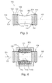
- Fig. 3 illustrates a noise reduction unit 100, wherein the middle section 103 comprises a flexible hose 163.
- the flexible hose comprises a constriction, such that the second diameter 113 is reduced compared to the first diameter 102 of the inlet section.
- the flexible hose 163 first constantly narrows towards the central axis 151 until reaching the maximum constriction depicted by the second diameter 113 and subsequently broadens such that the flexible hose is adaptable to the outlet section 104.
- the flexible hose is adapted to be expandable such that the second diameter 113 enlarges and the second diameter adapts to the first diameter 112 when being flown through by solid phase material.
- the flexible hose reduces the cross-section of the middle section such that the flow velocity of the transportation air or fluid in general may be reduced. This may reduce the amount of air used for the transportation process, which results in a noise reduction.
- the noise reduction unit may comprise a casing or a jacket in the area of the flexible hose, wherein the casing or jacket is adapted to protect the surrounding of the noise reduction unit from leak out liquid in case of a leak in the flexible hose.
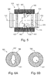
- Fig. 4 illustrates the noise reduction unit of Fig. 3 , wherein a pressurization element 170 surrounds the noise reduction unit in a circumferential manner.
- the pressurization element 170 comprises a gas volume 171 which is adapted to apply or exert pressure to the flexible hose in the direction indicate by arrows 172, that is towards the central axis 151 of the noise reduction unit.
- the pressurization element 170 and the noise reduction unit may for this purpose be connected substantially gas-tight or sealed.
- the pressurized gas volume and the material properties of the flexible hose are adapted to reduce the second diameter 113, wherein a solid phase material may still pass the noise reduction unit as the flexible hose and the gas volume allow an extension or enlargement of the second diameter.
- a solid phase material may still pass the noise reduction unit as the flexible hose and the gas volume allow an extension or enlargement of the second diameter.
- the gas volume and the flexible hose work as an attenuator or a damper with respect to the movement or fluctuation of the walls of the flexible hose in a direction orthogonal to the flow direction (that is: to and from the central axis) when being passed by solid phase material such that the second diameter needs to extend.
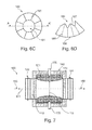
- Fig. 5 shows a noise reduction unit with a membrane 180 arranged in the middle section.
- the middle section is surrounded by a noise insulation element 140.
- the noise insulation element may alternatively surround the complete noise reduction unit.
- the membrane 180 is arranged such that it extends in a plane orthogonal to the flow direction 150, i.e. that the flow direction 150 is perpendicular to the membrane.
- the membrane comprises an opening 181 with a membrane opening diameter 182 which is less than the diameter of the noise reduction unit, in this case less than the second diameter of the middle section.
- the membrane may also be arranged in the inlet section or the outlet section as well as a multitude of membranes may be arranged in each of the inlet, middle and outlet sections.
- the membrane is adapted to turn down in direction of the flow direction 150 as indicated by the arrows 183. This will lead to an enlargement of the membrane opening diameter 182.
- the membrane may comprise elastically reversible material such that the membrane is in its original shape in an unloaded state of the noise reduction unit (that is: no material conveyance in progress) and the membrane will turn down according to the arrows 183 in case a vacuum suction is in progress and material flows in direction of the arrows 150.
- the pressure resistance of the membrane may vary such that the membrane turns down only in case solid phase material passes the opening 181. Otherwise (that is: air and liquid phase material pass the membrane opening) the membrane keeps its original shape as shown in Fig. 5 .
- Fig. 5 further depicts that turbulences 155 may occur in direction of the material flow behind the membrane, i.e. at the position at which an enlargement of the diameter from the membrane opening diameter 182 to the second diameter 113 occurs. These turbulences may further reduce the flow velocity of the material to be conveyed.
- the membrane 180 shown in Fig. 5 may also be used in connection with all of the embodiments shown above and hereinafter.
- Figs. 6A, 6B , 6C and 6D show exemplary embodiments of the membrane 180.
- the membrane comprises an outer edge 186, an inner edge 187 and the opening 181, wherein the form of the outer edge is adapted to the form of the noise reduction unit and the inner edge represents the contour or the membrane opening.
- the shown membrane shows a circular shape of the outer edge, several more forms of the membrane are possible.
- the outer edge 186 of the membrane 180 is adaptable to all possible profiles of the noise reduction system and a pipe or duct in general.
- the shape and the size of the opening may be adapted to the composition of the material to be conveyed, i.e. the opening may be smaller in case only liquid phase material is expected to pass the membrane.
- the membrane may comprise latex and/or silicone, for example.
- Fig. 6A shows a membrane with an elliptical opening.
- Fig. 6B shows a membrane with a circular opening.
- Figs. 6A and 6B are adapted to expand the opening due to elasticity or flexibility of the membrane.
- Fig. 6C shows a membrane comprising a multitude of stiffening elements 185 which are adapted to keep the membrane in its unloaded position, i.e. perpendicular to the flow direction of the material to be conveyed.
- the stiffening elements extend in a radial direction of the membrane and may avoid oscillating and fluttering of the membrane when being flown through by the material to be conveyed. Such an oscillation of the membrane may also generate noise, which is to be avoided.
- the stiffness of the stiffening elements may be variable and/or controllable, i.e. stiffening elements with differing stiffness may be used or stiffening elements whose stiffness is adaptable may be used.
- Fig. 6D shows a sectional view along the cutting line A-A' in Fig. 6C .
- the stiffening elements 185 extend from the outer edge 186 to the inner edge 187, wherein the inner edge is designed wavy such that the length of the inner edge is greater than the extend of the membrane opening. This enables the membrane to turn down without or with less material stretching, as the membrane comprises a material excess which forms the wavy course of the inner edge.
- Fig. 7 shows a noise reduction unit comparable to the embodiment shown in Fig. 4 but further comprises a gas duct 175 for letting the gas flow into and out of the gas volume 171.
- the pressurization element further comprises an elastically reversible element 173 which is arranged in the gas volume in order to apply or exert a pressure to the wall of the flexible hose toward the central axis 151.
- the gas duct 175 applies a pressure from the surroundings or ambience of the noise reduction unit to the gas volume 171.
- the cabin pressure may be applied to the gas volume, as the cabin pressure is in general higher than the pressure in the vacuum suction drain.
- the gas duct 175 is adapted to let out the gas of the gas volume 171 in case solid phase material passes the flexible hose and an extension of the flexible hose is necessary to let the solid phase material pass through. Thus, clogging of the flexible hose is avoided.
- fluid phase material such as liquid or gas
- the flexible hose constricts or contracts and gas will be let into the gas volume 171 through the gas duct 175.
- the gas duct 175 may comprise a pipe with a variable cross-section or profile, wherein the size of the cross-sectional area may vary, that is: the cross-sectional areas of the ducts differ from each other.
- the cross-sectional area of the gas duct 175 may be adapted to dampen the compensation flowing of the gas into and out of the gas volume 171 in case the diameter of the flexible hose varies due to being flown through by multiphase material.
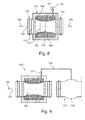
- Fig. 8 shows a noise reduction unit, wherein the pressurization element comprises a gas supply 176 for compressed gas, which gas supply 176 comprises a valve 177 such that the gas pressure in the gas volume may be controlled.
- the gas pressure in the gas volume 171 may be static or dynamic.
- the gas pressure may be brought to a given value prior to starting the conveying process through the vacuum suction drain and the noise reduction unit, wherein during the conveying process no or substantially no gas escapes from the gas volume.
- the static gas pressure may in particular be adapted to a projected flow velocity of the material to be conveyed or to a pressure difference used for the suction process, wherein a high pressure difference requires a higher gas pressure than an low pressure difference, as the high pressure difference leads to a higher flow velocity of the material to be conveyed.
- the static gas pressure may be dependent from the distance of a suction point to the waste collecting container, as a suction point close to the waste collecting container is addressed to a higher pressure difference than a suction point more distant to the waste collecting container.
- the gas pressure in the gas volume 171 of a noise reduction unit related to a suction point close to the waste collecting container may be higher than the gas pressure in the gas volume 171 of a noise reduction unit related to a suction point more distant to the waste collecting container.
- the gas pressure may vary during the conveying process.
- the gas pressure in the gas volume 171 may be high such that the diameter of the flexible hose is tight and an initial noise when starting the suction process is kept low.
- the gas pressure may be reduced in order to allow an expansion or extension of the diameter of the flexible hose such that the material to be conveyed is allowed to pass the noise reduction unit.
- the static and the dynamic case of the gas pressure in the gas volume may be combined, i.e. the gas pressure in the gas volume is static prior to starting the conveying process and varies during the conveying process.
- Fig. 8 illustrates that the flexible hose 163 may extend until the wall of the flexible hose achieves the dotted line 164 representing the extend of the flexible hose which corresponds to the first diameter 112 such that solid phase material does not lead to clogging in the middle section.
- a perforated sheet may be arranged such that the gas may pass through the perforations when the wall of the flexible hose extends towards or away from the central axis.
- the flexible hose may be adapted for folding or skin wrinkling, wherein the edges of the folds extend parallel to the flow direction 150.
- the folds may stabilize the flexible hose and may avoid vibrations or oscillations of the flexible hose, thus avoiding a noise generations due to material vibrations.
- Fig. 9 illustrates a noise reduction unit 100 and an outlet pipe 190 which are both interconnected via a compressed gas supply 176.
- the noise reduction unit 100 can be any embodiment of the noise reduction unit described above and hereinafter.
- the noise reduction unit 100 is adapted for being connected with its outlet section to the outlet pipe 190.
- the outlet pipe 190 comprises a broadened section 191.
- a broadened section 191 In general, in a pipe flown through by a fluid which pipe comprises a broadened section, an increased pressure will arise in the broadened section, wherein the pressure increases corresponding to the increased flow velocity of the conveyed fluid.
- the compressed gas supply 176 connects the broadened section 191 of the outlet pipe 190 with the gas volume of the pressurization element surrounding the noise reduction unit, in particular the flexible hose of the middle section.
- an increased flow velocity of the material to be conveyed leads to an increased pressure in the broadened section 191 which increased pressure is coupled to the gas volume of the pressurization element and for its part leads to a higher extension of the flexible hose which results in a reduced second diameter in the middle section of the noise reduction unit.
- the reduced second diameter will reduce the flow velocity of the material to be conveyed.
- the system depicted in Fig. 9 may be a self-regulating system for the flow velocity of the material to be conveyed.
- the valve 177 in the gas supply 176 may be adapted to close or open the gas supply or to partially close the cross-section of the gas supply such that the transmission of the gas pressure in the broadened section 191 may be delayed or reduced such that a change of the gas pressure in the broadened section is transmitted only partially to the gas volume of the pressurization element.
- the change of the fluid pressure in the broadened section may be transmitted at a given ratio of 2 to 1 (that is: half of the gas pressure in the broadened section is transmitted to the gas volume) to the gas volume.
- ratios are possible such as 4 to 1 or 10 to 1.
- the ratio may be adjusted by means of the valve 177.
- Fig. 10 illustrates the system depicted in Fig. 9 and updated with a control system for adjusting the transmission of the gas pressure from the broadened section 191 to the gas volume of the pressurization element.
- the control system comprises a controller unit 200 which is connected to a pressure detector 202, a noise detector 205 and to the valve 177 in the gas supply 176.
- the controller unit is adapted to receive the sampled gas pressure in the broadened section from the pressure detector 202 and a noise level acquired by the noise detector 205. Depending on the acquired noise and pressure values, the controller unit may initiate a modification of the valve 177 such that the transmitted gas pressure from the broadened section 191 to the gas volume may increase or decrease and the flow velocity of the material to be conveyed is being reduced or increased, respectively.
- the controller unit may be adapted to adjust the valve such that the flow velocity of the material to be conveyed varies dependent on a given nominal value of the noise level.
- Fig. 11 shows an exemplary embodiment of the noise reduction unit similar to that depicted in Fig. 9 except that the gas supply 176 is connected to a gas funnel 178 which is adapted to soak up a pressure in the inlet pipe 210.
- the gas funnel 178 leads the pressure in the inlet pipe 210 via the gas supply 176 to the gas volume 171 such that the pressure in the gas volume either increases or decreases which results in that the constriction of the flexible hose, that is the diameter 113, either decreases or increases, respectively.
- An increases flow velocity which corresponds to an increased pressure level in the inlet pipe 210 leads to an increased pressure in the gas volume 171 which further leads to a decreased diameter 113 of the flexible hose, such that the flow velocity of the material to be conveyed will be reduced.
- Fig. 11 depicts the inlet pipe 210 for connecting to the inlet section of the noise reduction unit.
- the gas funnel 178 may be arranged in an air intake pipe used for taking in air for the conveying process.
- the pipe 210 shown in Fig. 11 corresponds to the air intake pipe and the suction point is arranged between the air intake pipe and the noise reduction unit 100 shown in Fig. 11 .
- the air soaked in through the air intake pipe applies to the gas funnel and is lead through the gas supply 176 to the gas volume 171.
- the gas funnel 178 is not addressed to the multiphase material to be conveyed.
- the diameter of the gas funnel i.e. the diameter at the largest opening of the gas funnel
- the diameter of the air intake pipe may vary such that the ratio of the diameter of the gas funnel and the air intake pipe is adaptable in order to affect the gas pressure in the gas volume 171.
- the air circulation from the air intake pipe through the suction point, the vacuum suction pipe and the noise reduction unit may be a closed circuit, i.e. the transportation air enters the said closed circuit substantially through the air intake pipe.
- Fig. 12 illustrates a vacuum suction system 300 with a first vacuum suction point 310, a second vacuum suction point 320 and a third vacuum suction point 330.
- the suction points are connected via a first drain 311, second drain 321 and third drain 331, respectively to a main drain 340, which main drain is connected to the waste collecting container 350.
- a first opening valve 315, second opening valve 325 and third opening valve 335 is arranged in the first drain, second drain and third drain, respectively.
- a noise reduction unit 100 is arranged in each of the first drain, second drain and third drain.
- the noise reduction unit shown in Fig. 12 may be a noise reduction unit as described above and hereinafter, but it can be used any other means for reducing the flow velocity in the first, second and third drain.
- the waste collecting container is connected to a vacuum via the vacuum inlet drain 370 in order to introduce a vacuum into the drains of the vacuum suction system.
- a vacuum in the waste collecting container 350 enables the conveyance of material through the suction drains from the suction points to the collecting container as the pressure in the surroundings of the vacuum suction points is higher than the pressure in the collecting container.
- the vacuum inlet drain 370 comprises a vacuum pump 371 for generating a vacuum in case the pressure difference to the surroundings (that is: outside of the dashed box, which depicts a closed pressure isolated system) is not sufficient for ensuring the conveying process of the material to be conveyed.
- the vacuum inlet drain 370 comprises a vacuum inlet valve 371 for leading vacuum into the collecting container.
- the collecting container further comprises a waste disposal drain 360 with a waste disposal valve 365 for disposing the waste.
- the noise reduction units 100 arranged in the first, second and third drain are adapted for reducing the flow velocity of the material to be conveyed through the corresponding vacuum suction drains.
- the third vacuum suction point 330 is arranged most distant to the waste collecting container, the pressure difference for conveying the material to be conveyed has to be higher than at the first vacuum suction point due to the pressure reducing effect of the vacuum suction drains itself, i.e. the longer the vacuum suction drain is, the more will a pressure difference be reduced by the volume of the vacuum suction drain.
- the vacuum suction system depicted in Fig. 12 allows an adjustment of flow velocity and thus of the noise level for each individual vacuum suction point.
- the generated noise does not only depend on the pressure difference of each vacuum suction point to the waste collecting container, as the flow velocity of the material to be conveyed may be adapted for each vacuum suction drain connecting a vacuum suction point to the waste collecting container.
- the opening valves 315, 325 and 335 are adapted to start a conveying process of material to be conveyed from the vacuum suction points to the waste collecting container.
- the length of the main drain and of the first, second or third drain corresponds to the distance between a vacuum suction point and the waste collecting container, i.e. the crucial point is the distance which has to be passed by the material to be conveyed.
- the pressure difference between the waste collecting container and that one of the vacuum suction points arranged at the largest distance to the waste collecting container may be adapted such that the noise level generated at this vacuum suction point corresponds to the minimum noise level, i.e. the conveying velocity corresponds to the minimum velocity which ensures a reliable conveyance of the material.
- the pressure difference may be to high for the vacuum suction points arranged at a lower distance to the waste collecting container such that the flow velocity and the noise level in these suction points is higher than necessary for a reliable conveyance of material.
- a noise reduction unit for reducing the flow velocity may be arranged in the respective vacuum suction drains.
- the distance of the vacuum suction points to the waste collecting container may be between 3 m and 40 m.
- the vacuum suction system as described above and hereinafter is an open loop system, as the material to be conveyed through the vacuum suction drains is fed externally.
- One of the noise reduction units may be adapted to reduce the initial noise in the first phase of the conveying process when almost the complete conveyed material is the transport air and another one of the noise reduction units may be adapted to reduce the noise during the conveyance of the multiphase material.
- Fig. 13 shows an aircraft with a vacuum suction system as described above and hereinafter.
- the dashed box shown in Fig. 12 schematically depicts the passenger compartment of the aircraft, as this volume is separated from the surroundings such that there is a pressure difference between the passenger compartment and the surroundings, in particular in a flight phase of the aircraft.
- the pressure difference facilitates the conveying process through the vacuum suction drains.
- the vacuum suction points may be a toilet bowl, an urinal, a wash water basin or a ventilation element.
Landscapes
- Engineering & Computer Science (AREA)
- Aviation & Aerospace Engineering (AREA)
- Health & Medical Sciences (AREA)
- Life Sciences & Earth Sciences (AREA)
- Hydrology & Water Resources (AREA)
- Public Health (AREA)
- Water Supply & Treatment (AREA)
- Mechanical Engineering (AREA)
- Pipe Accessories (AREA)
- Cleaning In General (AREA)
Abstract
Description
- The present invention relates to a noise reduction unit for inserting in a vacuum suction drain, a vacuum system and an aircraft with a vacuum system.
- The term "vacuum system" and "vacuum suction drain" refers to special pneumatic conveyors. Generally speaking, in such conveyors transportation takes place in that a pressure difference is applied to the material to be conveyed, i.e. the material to be conveyed is entrained in the fluid flow generated as a result of the pressure difference, wherein generally speaking air is used as the transport medium.
- Especially in aircraft, vacuum systems are used for the transportation of waste from the cabin, for example from toilets or galleys, to a central waste collecting tank. In this arrangement the material to be conveyed is conveyed to the waste collecting tank by way of a pipeline network, i.e. vacuum suction drains. Negative pressure in the waste collecting tank in relation to the cabin pressure provides the required pressure difference.
- In aircraft with pressurized cabins the pressure difference between the cabin and the environment is used directly to generate the negative pressure for pneumatic conveyance. When this pressure difference is insufficient, e.g. on the tarmac or at low altitudes, the required pressure difference is generated by a compressor.
- In the case of toilets with a pneumatic conveyor system in aircraft systems, often a loud noise level arises. This noise is even noticed by the passengers in the cabin and is perceived by passengers to be uncomfortable.
-
DE 10 2005 013 566 Al andUS 2012/0014757 Al describe an arrangement for adapting the transportation behavior of material to be conveyed through drains of a vacuum system wherein a valve is arranged in a vacuum suction drain. - It may be seen as an object of the present invention to provide an alternative noise reduction unit for vacuum suction drains with improved noise damping characteristics.
- The object of the present invention is solved by the subject-matter of the independent claims, wherein further embodiments are incorporated in the dependent claims.
- According to an aspect of the invention, a noise reduction unit for inserting in a vacuum suction drain is adapted to be flown through by a material to be conveyed through the vacuum suction drain, wherein the noise reduction unit comprises an inlet section with a first diameter, a middle section with a second diameter and an outlet section with a third diameter, wherein the middle section is arranged between the inlet section and the outlet section, wherein the middle section is adapted to affect a flow velocity reduction of the material to be conveyed from the inlet section to the outlet section and wherein the second diameter differs from both the first diameter and the third diameter.
- The vacuum suction drain may be a pipe of a vacuum suction system, which vacuum suction system may be adapted for conveying material from a suction point to a collection point, for example from a first container like a wash basin or toilet bowl, i.e. the suction point, to a second container like a waste collection container, i.e. the second container.
- The material to be conveyed may in particular be a multiphase material, i.e. consisting of liquid phase material and solid phase material.
- The noise reduction unit may be adapted for modular insertion in the vacuum suction drain such that the material to be conveyed flows through the vacuum suction drain and as part of this flowing or suction process flows through the noise reduction system. The noise reduction unit may be inserted additional in an existing system of vacuum suction drains as well as in a mounting process prior to an initial operation of the vacuum suction drain.
- The inlet section and the outlet section of the vacuum suction unit connect the noise reduction unit to the vacuum suction drain, wherein the material to be conveyed flows through the noise reduction unit in a direction from the inlet section via the middle section to the outlet section.
- The middle section is adapted to affect a flow velocity reduction of the material to be conveyed. The middle section may also reduce the flow velocity of the air which serves as the transportation medium for the material to be conveyed.
- In general, the suction of the material to be conveyed in vacuum systems occurs because of a pressure difference between the suction point and the waste collection container. During the conveying process, i.e. the movement and motion of the material to be conveyed through the vacuum suction drain, this pressure difference decreases gradually as air is soaked into the waste collection container. Thus, the initial pressure difference has to be high enough such that the material to be conveyed passes the whole length of the vacuum suction drain. In particular the high pressure difference when starting the conveying process causes an unpleasant and inconvenient noise comparable to a burst noise or a bang. Reducing the initial pressure difference is not an alternative, as then there is a danger that the material to be conveyed does not pass the whole length of the vacuum suction drain. Instead, the noise reduction unit as described above and hereinafter reduces the velocity of the material to be conveyed directly when starting the suction process. Thus, the suction pressure will be sustained for a longer time, as the passed air volume and material to be conveyed volume per unit of time will be decreased.
- In other words, the initial conveying velocity will be reduced (which also reduces the generated noise during the suction process), such that the pressure difference will be sustained for a longer time instead of having a high initial conveying velocity which results in a high initial noise as usual by now.
- The noise reduction unit as described above and hereinafter may be used in particular in vacuum suction systems like vacuum toilets.
- According to a further embodiment of the invention, the second diameter differs from the first diameter such that the flow of the material to be conveyed through the vacuum suction drain causes turbulences in the noise reduction unit and/or in the vacuum suction drain, wherein the turbulences reduce the effective flow cross-section of the vacuum suction drain such that the flow velocity of the material to be conveyed is reduced.
- In particular, the second diameter may be greater than the first diameter such that the turbulences occur at the transition section from the first diameter of the inlet section to the second diameter of the middle section. These turbulences will increasingly arise with increased velocity of the conveyed material through the vacuum suction drain and the noise reduction unit. Thus, the velocity of the material to be conveyed and of the air used for conveying the material will be reduced in the initial phase of the suction process and the noise which arises in conjunction with the conveying velocity will be reduced.
- According to a further embodiment of the invention, the second diameter is greater than the first diameter and the enlargement of the second diameter with respect to the first diameter is adapted to cause the turbulences in the flow of the material to be conveyed.
- The transition from the inlet section with the first diameter to the middle section with the second diameter may be graded, stepped or rounded as described below in more detail. The transition may be designed depending on the material to be conveyed and in particular the proportion of transporting air, liquid or fluid phase material and solid material.
- As the second diameter of the middle section is greater than the first diameter of the first section, which first diameter corresponds to the diameter of the vacuum suction drain connected to the inlet section, there is no danger that material passing the vacuum suction drain may cause blockage or clogging in the noise reduction unit.
- According to a further embodiment of the invention, the second diameter is less than the first diameter and the reduction of the second diameter with respect to the first diameter is adapted to reduce the flow velocity of the material to be conveyed.
- As the second diameter of the middle section is less than the first diameter, the cross-section of the noise reduction unit is reduced such that in particular a flow velocity of the transportation air in the initial phase of the conveying process is reduced which may also reduce the noise when starting the suction process and the noise of the suction process itself.
- According to a further embodiment of the invention, the middle section comprises a flexible hose, wherein the flexible hose is arranged between the inlet section and the outlet section, wherein the flexible hose comprises a constriction, which corresponds to the second diameter.
- The flexible hose is flown through by the material to be conveyed during the suction process. The flexible hose comprises a wall which is adapted to stretch or expand in a direction orthogonal to the flow direction, i.e. in a radial direction of the hose. In other words, two opposite points of the wall of the flexible hose are moving towards each other and away from each other when the flexible hose expands or contracts, respectively.
- In an unloaded state of the vacuum suction drain and the noise reduction unit, i.e. when no material or just transportation air flows through the noise reduction unit, the flexible hose is in the contracted state such that the cross-section of the middle section, that is the flexible hose, is reduced and the flow velocity of the transportation air is reduced. When the material to be conveyed passes the flexible hose it will expand or stretch such that solid phase material may pass the flexible hose without blocking or clogging it.
- Once again, this structure or design of the noise reduction unit will reduce the velocity of the transport air used for transporting the material to be conveyed without reducing the initial pressure difference between the suction point and the collecting container such that the pressure difference ensures that the material to be conveyed will pass the whole length of the vacuum suction drain and yet the initial suction noise will be reduced.
- In order to avoid adhesion of parts of the material to be conveyed the flexible hose and/or the middle section as described above and hereinafter may comprise an anti-adhesive layer on a part of an inner surface or the entire inner surface, that is the surface of the inlet section, middle section and/or the outlet section towards a central axis of the noise reduction unit. The anti-adhesive layer may comprise Teflon or a material comprising Sol-gel, for example.
- According to a further embodiment of the invention, the flexible hose comprises a material tension, which material tension results in a constriction of the flexible hose, i.e. the constriction of the flexible hose is a result of a material tension of the flexible hose.
- Hence, the flexible hose may comprise an elastically reversible material which is adapted to keep the flexible hose in the contracted state in its original position. In case that solid phase material passes the flexible hose, it will expand from its original position such that the second diameter enlarges and the solid phase material is able to pass the flexible hose.
- According to a further embodiment of the invention, the noise reduction unit as described above and hereinafter comprises a pressurization element, which is adapted to cause the constriction of the flexible hose.
- The pressurization element may be arranged to support or replace the material tension of the flexible hose of the middle section. The pressurization element may be a circumferential element arranged at the middle section of the noise reduction unit and adapted to press the wall of the flexible hose towards the central axis of the noise reduction unit.
- According to a further embodiment of the invention, the pressurization element comprises a gas volume which is adapted to press the wall of the flexible hose towards the central axis of the noise reduction unit.
- Thus, the pressurization element is adapted to apply a pressure by means of the gas to the flexible hose, such that the flexible hose is pressed towards the central axis of the noise reduction unit in order to reduce the cross-section of the middle section. Further on, the pressurization element may comprise an elastic cushion, a liquid or a foam which is adapted to keep the flexible hose in an unloaded state of the vacuum suction drain in its original shape, i.e. to keep the flexible hose constricted, but allows an enlargement of the flexible hose when being passed by solid phase material.
- According to a further embodiment of the invention, the gas pressure of the gas volume is controllable, wherein the controlled gas pressure is adapted to vary the second diameter, i.e. the extent of the flexible hose, wherein an increased gas pressure causes a greater constriction of the flexible hose such that the second diameter is reduced.
- The gas pressure may be controlled in order to increase or decrease such that the gas volume increases or decreases, respectively. Corresponding to the varied gas pressure and the according gas volume the flexible hose will become stretched or released, wherein the second diameter gets smaller or larger when the gas volume increases and decreases, respectively.
- A reduced second diameter reduces the cross-section of the flexible hose such that a flow velocity of the transportation air and the material to be conveyed is reduced. As to not result in blockage or clogging, the flexible hose and the gas volume allow an expansion of the second diameter, in particular when being passed by solid phase material.
- The gas pressure may be controlled by a control loop or control system, wherein the noise originated in conveying material through the vacuum suction drain may be the control variable. The noise may be detected by a microphone or any other sensor suitable for detecting noise or a noise level. In general, the control loop may increase the gas pressure (that is: reduce the second diameter, which results in a reduction of the flow velocity of the material to be conveyed) when the noise level exceeds a given threshold value.
- Of course there may be used other control variables than the produced noise like the weight of the material to be conveyed or the composition of the multiphase material. The gas pressure may be increased in case there are no solid phase elements in the material to be conveyed such that the cross-section of the flexible hose or the middle section in general may be smaller and the flow velocity is reduced.
- The gas pressure may vary during the transportation of the material to be conveyed or may be constant for the time period of a single transportation process, i.e. the gas pressure may be determined prior to each single transportation process, wherein the detected control variable during the previous transportation process determines the gas pressure of the following transportation process.
- According to a further embodiment of the invention, the pressurization element comprises an elastically reversible element which is adapted to press the wall of the flexible hose towards the central axis of the noise reduction unit.
- The elastically reversible element may be a foam like foamed plastic or foamed material in general. The foam may be adapted to bring the flexible hose in its constricted position such that the second diameter is being reduced. As the foam is elastically reversible, the second diameter is able to vary in case solid phase material passes the middle section and a blockage or clogging is avoided.
- The elastically reversible element may be used as an alternative or additional to the pressurized gas volume. In the latter case, the gas volume may intrude the hollow spaces or cavities of the foam.
- According to a further embodiment of the invention, the noise reduction unit as described above and hereinafter comprises an elastic membrane which extends in a plane orthogonal to the flow direction and comprises an opening for being flown through by the material to be conveyed, wherein the elastic membrane is adapted to extend when being flown through by the material to be conveyed, wherein the opening of the membrane is adapted to reduce the effective cross-section of the noise reduction unit such that a flow velocity of the material to be conveyed is reduced.
- In an unloaded state of the noise reduction unit the membrane extends towards the central axis of the noise reduction unit. The opening of the membrane represents the minimum cross-section of the noise reduction unit. Thus, when starting the suction process and during the suction process, the amount of transportation air flowing through the noise reduction unit is being reduced such that the suction noise and in particular the initial noise when starting the suction process is being reduced. After starting the suction process the transportation air and the conveyed material will result in extending the opening of the membrane.
- As the diameter of the opening will not directly adapt to the diameter of the noise reduction unit there will occur a transition from a narrow cross-section to a wider cross-section such that turbulences will occur at this point. The effect of these turbulences may further reduce the flow velocity of the transportation air and of the material to be conveyed as described above in more detail.
- The membrane may be arranged in the inlet section, in the middle section or in the outlet section and may be combined with any of the means for reducing the flow velocity of the material to be conveyed described above and hereinafter.
- According to another aspect of the invention, a vacuum suction system is provided which comprises a first vacuum suction point, a second vacuum suction point, a waste collecting container, a first drain for connecting the first vacuum suction point to the waste collecting container, a second drain for connecting the second vacuum suction point to the waste collecting container and a first noise reduction unit, wherein the first vacuum suction point is arranged at a first distance to the waste collecting container and the second vacuum suction point is arranged at a second distance to the waste collecting container and wherein the first noise reduction unit is arranged in the first drain to adapt a first flow velocity in the first drain to a second flow velocity in the second drain.
- In general the flow velocity of material to be conveyed in a vacuum suction drain depends on the pressure difference between a suction point and a collection point. In vacuum suction systems with a multitude of suction points and a corresponding number of drains the pressure difference further depends on the length of the drains as the air capacity or the air volume of the drains have an influence to the pressure difference between the collection point and every single suction point. The pressure difference has to be adapted in order to ensure that the material to be conveyed passed the longest drain. This may lead to the effect that the pressure difference is too high for shorter drains which results in a higher noise level in the vicinity of suction points arranged close to the collection point.
- The vacuum suction system as described above and hereinafter may avoid the different noise level generated by suction points connected to the waste collecting container by means of drains with different lengths as a noise reduction unit in a first drain is adapted to adapt the flow velocity of the material to be conveyed through the first drain. In particular, the noise reduction unit may be arranged in the shorter one of the first drain and the second drain, such that the flow velocity of the material to be conveyed through the shorter drain is reduced.
- Thus, a demand oriented providing of pressure difference and flow velocity for a vacuum suction process depending on the distance of the suction point to the waste collecting container is provided. The vacuum suction system as described above and hereinafter may in particular reduce the noise level produced by vacuum suction points close to the waste collecting container.
- The vacuum suction system is adapted to reduce the flow velocity in short drains, wherein the pressure difference provided by the system is specified to ensure a transportation process or vacuum suction process with respect to the drains having the maximum length.
- According to a further embodiment of the invention, the vacuum suction system comprises a second noise reduction unit which is arranged in the second drain to adapt a second flow velocity in the second drain.
- Thus, the flow velocity in the first drain and the flow velocity in the second drain may be adapted independent from each other and independent from the initial pressure difference between each of the suction points and the waste collecting container.
- According to a further embodiment of the invention, are the first noise reduction unit and the second noise reduction unit a noise reduction unit as described above and hereinafter.
- Hence, the vacuum suction system may comprise any noise reduction unit for reducing the flow velocity of the transportation air and the material to be conveyed in one drain or a multitude of drains or a noise reduction unit as described in more detail above and hereinafter.
- According to another aspect of the invention, an aircraft with a vacuum suction system as described above and hereinafter is provided, wherein the first vacuum suction point and the second vacuum suction point are one element of the group consisting of a vacuum toilet system, a waste water basin and a vacuum ventilation system.
- The vacuum suction system may of course be used in other means of transport as land vehicles and water vehicles, for example in buses, trains and ships.
- These and other aspects of the present invention will become apparent from and elucidated with reference to the embodiments described hereinafter.
- Exemplary embodiments of the invention will be described in the following with reference to the following drawings.
-
Fig. 1 illustrates a noise reduction unit according to an exemplary embodiment of the invention. -
Fig. 2 illustrates a noise reduction unit according to a further exemplary embodiment of the invention. -
Fig. 3 illustrates a noise reduction unit according to a further exemplary embodiment of the invention. -
Fig. 4 illustrates a noise reduction unit according to a further exemplary embodiment of the invention. -
Fig. 5 illustrates a noise reduction unit according to a further exemplary embodiment of the invention. -
Fig. 6A illustrates a membrane for a noise reduction system according to a further exemplary embodiment of the invention. -
Fig. 6B illustrates a membrane for a noise reduction system according to a further exemplary embodiment of the invention. -
Fig. 6C illustrates a membrane for a noise reduction system according to a further exemplary embodiment of the invention. -
Fig. 6D illustrates a sectional view of a membrane for a noise reduction system according to a further exemplary embodiment of the invention. -
Fig. 7 illustrates a noise reduction system according to a further exemplary embodiment of the invention. -
Fig. 8 illustrates a noise reduction system according to a further exemplary embodiment of the invention. -
Fig. 9 illustrates a noise reduction system according to a further exemplary embodiment of the invention. -
Fig. 10 illustrates a noise reduction system according to a further exemplary embodiment of the invention. -
Fig. 11 illustrates a noise reduction system according to a further exemplary embodiment of the invention. -
Fig. 12 illustrates a vacuum suction system according to an exemplary embodiment of the invention. -
Fig. 13 illustrates an aircraft with a vacuum suction system according to an exemplary embodiment of the invention. - It should be noted that the same reference signs may be used for similar or identical elements.
- The illustrations in the figures are diagrammatic and not to scale.
-
Fig. 1 illustrates anoise reduction unit 100 with aninlet section 102, amiddle section 103 and anoutlet section 104. The inlet section comprises afirst connector 122 and the outlet section comprises asecond connector 124, each for connecting the noise reduction unit into a vacuum suction drain (not shown). Anoise insulation element 140 surrounds or encloses the noise reduction unit circumferential. The inlet section comprises afirst damper 132 and the outlet section comprises asecond damper 134. - The
inlet section 102 has afirst diameter 112, themiddle section 103 has asecond diameter 113 and theoutlet section 104 has athird diameter 114. - The
noise reduction unit 100 is adapted to be flown through by material to be conveyed in the direction of thearrow 150, i.e. from the inlet section via the middle section to the outlet section. - The
second diameter 113 of themiddle section 103 is larger than thefirst diameter 112 of theinlet section 102. Thus, the extension of the diameter of the noise reduction unit from the inlet section to the middle section will causeturbulences 155 which may lower or reduce the kinetic energy of the transportation air and the material to be conveyed. This may in particular be used in connection with short vacuum suction drains (i.e. drains connecting a suction point to the waste collecting container, wherein the suction point is close to the waste collecting container) in which a reduction of the kinetic energy will not lead to an insufficient flow velocity. - The transition from the first diameter to the second diameter may be constructed in form of a stage or a terrace, as shown by the dashed
line 105A. Furthermore, this transition may be shaped as a rounded transition, in particular concave shaped as shown by thereference sign 105B or convex shaped. - The
turbulences 155 may result in vibrations of the noise reduction unit with an oscillation direction parallel and antiparallel to theflow direction 150. In order to avoid an increased noise level due to these vibrations thefirst damper 132 and thesecond damper 134 are adapted to absorb and damp the vibrations. - The first damper and the second damper may be adapted as part of the inlet section and the outlet section, respectively or for interconnecting the inlet section and the outlet section with the vacuum suction drain. In particular, the first damper and the second damper may be an elastic seal or gasket which is adapted to absorb vibrations.
- The third diameter may be identical to the first diameter or larger than the first diameter such that solid phase material may pass the outlet section without clogging the noise reduction unit.
-
Fig. 2 schematically shows a sectional view of a noise damper, wherein the effect of theturbulences 155 is pointed out. - The
arrows 150 indicate the flow direction of the material to be conveyed. At the transition point from theinlet section 102 to themiddle section 103, i.e. from the first diameter to the second diameter, which second diameter is larger than the first diameter and thus causesturbulences 155. - The
turbulences 155 rising at the transition point from the inlet section to the middle section may reduce the effective cross-section of the noise reduction unit, which is indicated by theeffective diameter 115 between the turbulences 155. Thus, theeffective diameter 115 will reduce the kinetic energy of the material flow even thought thesecond diameter 113 of themiddle section 104 is larger than thefirst diameter 112. - The embodiment of the
noise reduction unit 100 illustrated inFigs. 1 and 2 lowers the flow velocity of the material to be conveyed due to the turbulences rising at the broadening section at the transition from the inlet section to the middle section. Even though creating a resistance against the material flow, solid phase material may pass the noise reduction unit without clogging it, as the turbulences do not lead to a blockage. -
Fig. 3 illustrates anoise reduction unit 100, wherein themiddle section 103 comprises aflexible hose 163. The flexible hose comprises a constriction, such that thesecond diameter 113 is reduced compared to thefirst diameter 102 of the inlet section. - The specification of the
inlet section 102 and theoutlet section 104 ofFigs. 1 and 2 also apply to the embodiment shown inFig. 3 . - Viewing in
flow direction 150, theflexible hose 163 first constantly narrows towards thecentral axis 151 until reaching the maximum constriction depicted by thesecond diameter 113 and subsequently broadens such that the flexible hose is adaptable to theoutlet section 104. - In order not to be vulnerable to clogging by solid phase material the flexible hose is adapted to be expandable such that the
second diameter 113 enlarges and the second diameter adapts to thefirst diameter 112 when being flown through by solid phase material. In contrary to that, the flexible hose reduces the cross-section of the middle section such that the flow velocity of the transportation air or fluid in general may be reduced. This may reduce the amount of air used for the transportation process, which results in a noise reduction. - The noise reduction unit may comprise a casing or a jacket in the area of the flexible hose, wherein the casing or jacket is adapted to protect the surrounding of the noise reduction unit from leak out liquid in case of a leak in the flexible hose.
-
Fig. 4 illustrates the noise reduction unit ofFig. 3 , wherein apressurization element 170 surrounds the noise reduction unit in a circumferential manner. Thepressurization element 170 comprises agas volume 171 which is adapted to apply or exert pressure to the flexible hose in the direction indicate byarrows 172, that is towards thecentral axis 151 of the noise reduction unit. Thepressurization element 170 and the noise reduction unit may for this purpose be connected substantially gas-tight or sealed. - The pressurized gas volume and the material properties of the flexible hose are adapted to reduce the
second diameter 113, wherein a solid phase material may still pass the noise reduction unit as the flexible hose and the gas volume allow an extension or enlargement of the second diameter. Thus, the flow velocity of air and liquid phase material and the according transport noise may be reduced due to the reduced second diameter without being vulnerable to clogging due to the extensible second diameter. - The gas volume and the flexible hose work as an attenuator or a damper with respect to the movement or fluctuation of the walls of the flexible hose in a direction orthogonal to the flow direction (that is: to and from the central axis) when being passed by solid phase material such that the second diameter needs to extend.
-
Fig. 5 shows a noise reduction unit with amembrane 180 arranged in the middle section. The middle section is surrounded by anoise insulation element 140. The noise insulation element may alternatively surround the complete noise reduction unit. - The
membrane 180 is arranged such that it extends in a plane orthogonal to theflow direction 150, i.e. that theflow direction 150 is perpendicular to the membrane. The membrane comprises anopening 181 with amembrane opening diameter 182 which is less than the diameter of the noise reduction unit, in this case less than the second diameter of the middle section. - It should be noted that the membrane may also be arranged in the inlet section or the outlet section as well as a multitude of membranes may be arranged in each of the inlet, middle and outlet sections.
- The membrane is adapted to turn down in direction of the
flow direction 150 as indicated by thearrows 183. This will lead to an enlargement of themembrane opening diameter 182. - The membrane may comprise elastically reversible material such that the membrane is in its original shape in an unloaded state of the noise reduction unit (that is: no material conveyance in progress) and the membrane will turn down according to the
arrows 183 in case a vacuum suction is in progress and material flows in direction of thearrows 150. - The pressure resistance of the membrane may vary such that the membrane turns down only in case solid phase material passes the
opening 181. Otherwise (that is: air and liquid phase material pass the membrane opening) the membrane keeps its original shape as shown inFig. 5 . -
Fig. 5 further depicts thatturbulences 155 may occur in direction of the material flow behind the membrane, i.e. at the position at which an enlargement of the diameter from themembrane opening diameter 182 to thesecond diameter 113 occurs. These turbulences may further reduce the flow velocity of the material to be conveyed. - The
membrane 180 shown inFig. 5 may also be used in connection with all of the embodiments shown above and hereinafter. -
Figs. 6A, 6B ,6C and 6D show exemplary embodiments of themembrane 180. The membrane comprises anouter edge 186, aninner edge 187 and theopening 181, wherein the form of the outer edge is adapted to the form of the noise reduction unit and the inner edge represents the contour or the membrane opening. - Even though the shown membrane shows a circular shape of the outer edge, several more forms of the membrane are possible. In particular, the
outer edge 186 of themembrane 180 is adaptable to all possible profiles of the noise reduction system and a pipe or duct in general. Furthermore, the shape and the size of the opening may be adapted to the composition of the material to be conveyed, i.e. the opening may be smaller in case only liquid phase material is expected to pass the membrane. - The membrane may comprise latex and/or silicone, for example.
-
Fig. 6A shows a membrane with an elliptical opening. -
Fig. 6B shows a membrane with a circular opening. - The embodiments shown in both
Figs. 6A and 6B are adapted to expand the opening due to elasticity or flexibility of the membrane. -
Fig. 6C shows a membrane comprising a multitude of stiffeningelements 185 which are adapted to keep the membrane in its unloaded position, i.e. perpendicular to the flow direction of the material to be conveyed. The stiffening elements extend in a radial direction of the membrane and may avoid oscillating and fluttering of the membrane when being flown through by the material to be conveyed. Such an oscillation of the membrane may also generate noise, which is to be avoided. The stiffness of the stiffening elements may be variable and/or controllable, i.e. stiffening elements with differing stiffness may be used or stiffening elements whose stiffness is adaptable may be used. -
Fig. 6D shows a sectional view along the cutting line A-A' inFig. 6C . The stiffeningelements 185 extend from theouter edge 186 to theinner edge 187, wherein the inner edge is designed wavy such that the length of the inner edge is greater than the extend of the membrane opening. This enables the membrane to turn down without or with less material stretching, as the membrane comprises a material excess which forms the wavy course of the inner edge. -
Fig. 7 shows a noise reduction unit comparable to the embodiment shown inFig. 4 but further comprises agas duct 175 for letting the gas flow into and out of thegas volume 171. - The pressurization element further comprises an elastically
reversible element 173 which is arranged in the gas volume in order to apply or exert a pressure to the wall of the flexible hose toward thecentral axis 151. - The
gas duct 175 applies a pressure from the surroundings or ambience of the noise reduction unit to thegas volume 171. For example in an aircraft the cabin pressure may be applied to the gas volume, as the cabin pressure is in general higher than the pressure in the vacuum suction drain. Thegas duct 175 is adapted to let out the gas of thegas volume 171 in case solid phase material passes the flexible hose and an extension of the flexible hose is necessary to let the solid phase material pass through. Thus, clogging of the flexible hose is avoided. When being passed by fluid phase material such as liquid or gas, the flexible hose constricts or contracts and gas will be let into thegas volume 171 through thegas duct 175. - The
gas duct 175 may comprise a pipe with a variable cross-section or profile, wherein the size of the cross-sectional area may vary, that is: the cross-sectional areas of the ducts differ from each other. - The cross-sectional area of the
gas duct 175 may be adapted to dampen the compensation flowing of the gas into and out of thegas volume 171 in case the diameter of the flexible hose varies due to being flown through by multiphase material. - In a similar manner,
Fig. 8 shows a noise reduction unit, wherein the pressurization element comprises agas supply 176 for compressed gas, whichgas supply 176 comprises avalve 177 such that the gas pressure in the gas volume may be controlled. - The gas pressure in the
gas volume 171 may be static or dynamic. - In the first case, that is: static, the gas pressure may be brought to a given value prior to starting the conveying process through the vacuum suction drain and the noise reduction unit, wherein during the conveying process no or substantially no gas escapes from the gas volume. The static gas pressure may in particular be adapted to a projected flow velocity of the material to be conveyed or to a pressure difference used for the suction process, wherein a high pressure difference requires a higher gas pressure than an low pressure difference, as the high pressure difference leads to a higher flow velocity of the material to be conveyed.
- In particular, the static gas pressure may be dependent from the distance of a suction point to the waste collecting container, as a suction point close to the waste collecting container is addressed to a higher pressure difference than a suction point more distant to the waste collecting container. Thus, the gas pressure in the
gas volume 171 of a noise reduction unit related to a suction point close to the waste collecting container may be higher than the gas pressure in thegas volume 171 of a noise reduction unit related to a suction point more distant to the waste collecting container. - In the second case, that is: dynamic, the gas pressure may vary during the conveying process. In a first phase of the conveying process, when in particular air passes through the noise reduction unit, the gas pressure in the
gas volume 171 may be high such that the diameter of the flexible hose is tight and an initial noise when starting the suction process is kept low. In a subsequent phase of the conveying process, the gas pressure may be reduced in order to allow an expansion or extension of the diameter of the flexible hose such that the material to be conveyed is allowed to pass the noise reduction unit. - Of course, the static and the dynamic case of the gas pressure in the gas volume may be combined, i.e. the gas pressure in the gas volume is static prior to starting the conveying process and varies during the conveying process.
- Furthermore,
Fig. 8 illustrates that theflexible hose 163 may extend until the wall of the flexible hose achieves the dottedline 164 representing the extend of the flexible hose which corresponds to thefirst diameter 112 such that solid phase material does not lead to clogging in the middle section. - Corresponding to the dotted
line 164, a perforated sheet may be arranged such that the gas may pass through the perforations when the wall of the flexible hose extends towards or away from the central axis. - The flexible hose may be adapted for folding or skin wrinkling, wherein the edges of the folds extend parallel to the
flow direction 150. The folds may stabilize the flexible hose and may avoid vibrations or oscillations of the flexible hose, thus avoiding a noise generations due to material vibrations. -
Fig. 9 illustrates anoise reduction unit 100 and anoutlet pipe 190 which are both interconnected via acompressed gas supply 176. Thenoise reduction unit 100 can be any embodiment of the noise reduction unit described above and hereinafter. Thenoise reduction unit 100 is adapted for being connected with its outlet section to theoutlet pipe 190. - The
outlet pipe 190 comprises a broadenedsection 191. In general, in a pipe flown through by a fluid which pipe comprises a broadened section, an increased pressure will arise in the broadened section, wherein the pressure increases corresponding to the increased flow velocity of the conveyed fluid. - As can be seen in
Fig. 9 , thecompressed gas supply 176 connects the broadenedsection 191 of theoutlet pipe 190 with the gas volume of the pressurization element surrounding the noise reduction unit, in particular the flexible hose of the middle section. - Thus, an increased flow velocity of the material to be conveyed leads to an increased pressure in the broadened
section 191 which increased pressure is coupled to the gas volume of the pressurization element and for its part leads to a higher extension of the flexible hose which results in a reduced second diameter in the middle section of the noise reduction unit. The reduced second diameter will reduce the flow velocity of the material to be conveyed. Hence, the system depicted inFig. 9 may be a self-regulating system for the flow velocity of the material to be conveyed. - The
valve 177 in thegas supply 176 may be adapted to close or open the gas supply or to partially close the cross-section of the gas supply such that the transmission of the gas pressure in the broadenedsection 191 may be delayed or reduced such that a change of the gas pressure in the broadened section is transmitted only partially to the gas volume of the pressurization element. For example, the change of the fluid pressure in the broadened section may be transmitted at a given ratio of 2 to 1 (that is: half of the gas pressure in the broadened section is transmitted to the gas volume) to the gas volume. Of course, other ratios are possible such as 4 to 1 or 10 to 1. In particular, the ratio may be adjusted by means of thevalve 177. -
Fig. 10 illustrates the system depicted inFig. 9 and updated with a control system for adjusting the transmission of the gas pressure from the broadenedsection 191 to the gas volume of the pressurization element. - The control system comprises a
controller unit 200 which is connected to apressure detector 202, anoise detector 205 and to thevalve 177 in thegas supply 176. - The controller unit is adapted to receive the sampled gas pressure in the broadened section from the
pressure detector 202 and a noise level acquired by thenoise detector 205. Depending on the acquired noise and pressure values, the controller unit may initiate a modification of thevalve 177 such that the transmitted gas pressure from the broadenedsection 191 to the gas volume may increase or decrease and the flow velocity of the material to be conveyed is being reduced or increased, respectively. - The controller unit may be adapted to adjust the valve such that the flow velocity of the material to be conveyed varies dependent on a given nominal value of the noise level.
-
Fig. 11 shows an exemplary embodiment of the noise reduction unit similar to that depicted inFig. 9 except that thegas supply 176 is connected to agas funnel 178 which is adapted to soak up a pressure in theinlet pipe 210. Thegas funnel 178 leads the pressure in theinlet pipe 210 via thegas supply 176 to thegas volume 171 such that the pressure in the gas volume either increases or decreases which results in that the constriction of the flexible hose, that is thediameter 113, either decreases or increases, respectively. An increases flow velocity, which corresponds to an increased pressure level in theinlet pipe 210 leads to an increased pressure in thegas volume 171 which further leads to adecreased diameter 113 of the flexible hose, such that the flow velocity of the material to be conveyed will be reduced. This interrelation between the flow velocity and the pressure in the inlet pipe on the one hand and the pressure in the gas volume and the diameter of the flexible hose on the other hand applies as well vice versa: on the one hand a high flow velocity and pressure in the inlet pipe results in a higher pressure in thegas volume 171 and a smaller diameter of the flexible hose such that the flow velocity is being reduced, on the other hand, a low flow velocity and pressure in the inlet pipe results in a lower pressure in thegas volume 171 and a greater diameter of the flexible hose such that the flow velocity may increase. Thevalve 177 is adapted to adjust the ratio of the transmitted pressure from the inlet pipe to the gas volume of the pressurization element. - Furthermore,
Fig. 11 depicts theinlet pipe 210 for connecting to the inlet section of the noise reduction unit. - In an alternative exemplary embodiment, the
gas funnel 178 may be arranged in an air intake pipe used for taking in air for the conveying process. In this embodiment, thepipe 210 shown inFig. 11 corresponds to the air intake pipe and the suction point is arranged between the air intake pipe and thenoise reduction unit 100 shown inFig. 11 . Thus, the air soaked in through the air intake pipe applies to the gas funnel and is lead through thegas supply 176 to thegas volume 171. Thegas funnel 178 is not addressed to the multiphase material to be conveyed. - In this alternative exemplary embodiment, the diameter of the gas funnel, i.e. the diameter at the largest opening of the gas funnel, and the diameter of the air intake pipe may vary such that the ratio of the diameter of the gas funnel and the air intake pipe is adaptable in order to affect the gas pressure in the
gas volume 171. The greater the diameter of the gas funnel is and the lower the diameter of the air intake pipe is, the higher gets the gas pressure applied to the gas volume through thegas supply 176. The air circulation from the air intake pipe through the suction point, the vacuum suction pipe and the noise reduction unit may be a closed circuit, i.e. the transportation air enters the said closed circuit substantially through the air intake pipe. -
Fig. 12 illustrates avacuum suction system 300 with a firstvacuum suction point 310, a secondvacuum suction point 320 and a thirdvacuum suction point 330. The suction points are connected via afirst drain 311,second drain 321 andthird drain 331, respectively to amain drain 340, which main drain is connected to thewaste collecting container 350. Afirst opening valve 315,second opening valve 325 andthird opening valve 335 is arranged in the first drain, second drain and third drain, respectively. Anoise reduction unit 100 is arranged in each of the first drain, second drain and third drain. - It should be noted that the noise reduction unit shown in
Fig. 12 may be a noise reduction unit as described above and hereinafter, but it can be used any other means for reducing the flow velocity in the first, second and third drain. - The waste collecting container is connected to a vacuum via the
vacuum inlet drain 370 in order to introduce a vacuum into the drains of the vacuum suction system. A vacuum in thewaste collecting container 350 enables the conveyance of material through the suction drains from the suction points to the collecting container as the pressure in the surroundings of the vacuum suction points is higher than the pressure in the collecting container. - The
vacuum inlet drain 370 comprises avacuum pump 371 for generating a vacuum in case the pressure difference to the surroundings (that is: outside of the dashed box, which depicts a closed pressure isolated system) is not sufficient for ensuring the conveying process of the material to be conveyed. - Furthermore, the
vacuum inlet drain 370 comprises avacuum inlet valve 371 for leading vacuum into the collecting container. - The collecting container further comprises a
waste disposal drain 360 with awaste disposal valve 365 for disposing the waste. - The
noise reduction units 100 arranged in the first, second and third drain are adapted for reducing the flow velocity of the material to be conveyed through the corresponding vacuum suction drains. As the thirdvacuum suction point 330 is arranged most distant to the waste collecting container, the pressure difference for conveying the material to be conveyed has to be higher than at the first vacuum suction point due to the pressure reducing effect of the vacuum suction drains itself, i.e. the longer the vacuum suction drain is, the more will a pressure difference be reduced by the volume of the vacuum suction drain. - The vacuum suction system depicted in
Fig. 12 allows an adjustment of flow velocity and thus of the noise level for each individual vacuum suction point. Thus, the generated noise does not only depend on the pressure difference of each vacuum suction point to the waste collecting container, as the flow velocity of the material to be conveyed may be adapted for each vacuum suction drain connecting a vacuum suction point to the waste collecting container. - The opening
valves - The length of the main drain and of the first, second or third drain corresponds to the distance between a vacuum suction point and the waste collecting container, i.e. the crucial point is the distance which has to be passed by the material to be conveyed. Derogating from the representation in
Fig. 12 , the pressure difference between the waste collecting container and that one of the vacuum suction points arranged at the largest distance to the waste collecting container may be adapted such that the noise level generated at this vacuum suction point corresponds to the minimum noise level, i.e. the conveying velocity corresponds to the minimum velocity which ensures a reliable conveyance of the material. In this case, the pressure difference may be to high for the vacuum suction points arranged at a lower distance to the waste collecting container such that the flow velocity and the noise level in these suction points is higher than necessary for a reliable conveyance of material. Thus, a noise reduction unit for reducing the flow velocity may be arranged in the respective vacuum suction drains. - For example, the distance of the vacuum suction points to the waste collecting container may be between 3 m and 40 m.
- In contrary to a closed loop system, the vacuum suction system as described above and hereinafter is an open loop system, as the material to be conveyed through the vacuum suction drains is fed externally.
- Even though the depicted vacuum suction system comprises three vacuum suction points, the inventive idea applies to vacuum suction systems with any number of vacuum suction points.
- Of course there may be arranged two or more noise reduction units in one vacuum suction drain. One of the noise reduction units may be adapted to reduce the initial noise in the first phase of the conveying process when almost the complete conveyed material is the transport air and another one of the noise reduction units may be adapted to reduce the noise during the conveyance of the multiphase material.
-
Fig. 13 shows an aircraft with a vacuum suction system as described above and hereinafter. - The dashed box shown in
Fig. 12 schematically depicts the passenger compartment of the aircraft, as this volume is separated from the surroundings such that there is a pressure difference between the passenger compartment and the surroundings, in particular in a flight phase of the aircraft. The pressure difference facilitates the conveying process through the vacuum suction drains. - The vacuum suction points may be a toilet bowl, an urinal, a wash water basin or a ventilation element.
- In the claims, the word "comprising" does not exclude other elements or steps and the indefinite article "a" or "an" does not exclude a plurality.
-
- 100
- noise reduction unit
- 102
- inlet section
- 103
- middle section
- 104
- outlet section
- 105A
- transition region
- 105B
- transition region
- 112
- first diameter
- 113
- second diameter
- 114
- third diameter
- 115
- effective cross-section
- 122
- first connector
- 124
- second connector
- 132
- first damper
- 134
- second damper
- 140
- noise insulation element
- 150
- flow direction
- 151
- central axis
- 155
- flow turbulences
- 163
- flexible hose
- 164
- expanded position of the flexible hose
- 170
- pressurization element
- 171
- gas volume
- 172
- pressure direction
- 173
- elastically reversible element
- 175
- gas duct
- 176
- compressed gas supply
- 177
- valve
- 178
- gas funnel
- 180
- membrane
- 181
- membrane opening
- 182
- diameter of the membrane opening in an unloaded state
- 183
- moving direction of the membrane in a loaded state
- 185
- stiffening element
- 186
- outer edge of the membrane
- 187
- inner edge of the membrane
- 190
- outlet pipe
- 191
- broadened section of the outlet pipe
- 200
- controller unit
- 202
- pressure detector
- 205
- noise detector
- 210
- inlet pipe
- 300
- vacuum suction system
- 310
- first vacuum suction point
- 311
- first drain
- 315
- first opening valve
- 320
- second vacuum suction point
- 321
- second drain
- 325
- second opening valve
- 330
- third vacuum suction point
- 331
- third drain
- 335
- third opening valve
- 340
- main drain
- 350
- waste collecting container
- 360
- waste disposal drain
- 365
- waste disposal valve
- 370
- vacuum inlet drain
- 371
- vacuum pump
- 375
- vacuum inlet valve
- 400
- aircraft
Claims (15)
- Noise reduction unit (100) for inserting in a vacuum suction drain (190, 210), wherein the noise reduction unit is adapted to be flown through by a material to be conveyed through the vacuum suction drain, the noise reduction unit comprising:an inlet section (102) with a first diameter (112);a middle section (103) with a second diameter (113);an outlet section (104) with a third diameter (114);wherein the middle section is arranged between the inlet section and the outlet section;wherein the middle section is adapted to affect a flow velocity reduction of the material to be conveyed from the inlet section to the outlet section;wherein the second diameter differs from both the first diameter and the third diameter.
- Noise reduction unit (100) according to claim 1,
wherein the second diameter differs from the first diameter such that the flow (150) of the material to be conveyed through the noise reduction unit causes turbulences (155) in the vacuum suction drain;
wherein the turbulences reduce the effective cross-section (115) of the vacuum suction drain such that the flow velocity of the material to be conveyed is reduced. - Noise reduction unit (100) according to claim 2,
wherein the second diameter is greater than the first diameter and the enlargement of the second diameter with respect to the first diameter is adapted to cause the turbulences in the flow of the material to be conveyed. - Noise reduction unit (100) according to claim 1,
wherein the second diameter is less than the first diameter and the reduction of the second diameter with respect to the first diameter is adapted to reduce the flow velocity of the material to be conveyed. - Noise reduction unit (100) according to claim 4,
wherein the middle section comprises a flexible hose (163);
wherein the flexible hose is arranged between the inlet section (102) and the outlet section (104);
wherein the flexible hose comprises a constriction, which constriction corresponds to the second diameter (113). - Noise reduction unit (100) according to claim 5,
wherein the flexible hose comprises a material tension, which material tension results in a constriction of the flexible hose. - Noise reduction unit (100) according to one of claims 5 and 6,
further comprising a pressurization element (170), which is adapted to cause the constriction of the flexible hose. - Noise reduction unit (100) according to claim 7,
wherein the pressurization element comprises a gas volume (171);
which gas volume is adapted to press the wall of the flexible hose towards a central axis (151) of the noise reduction unit. - Noise reduction unit (100) according to claim 8,
wherein a gas pressure of the gas volume is controllable;
wherein the controlled gas pressure is adapted to vary the second diameter;
wherein an increased gas pressure causes a greater constriction of the flexible hose such that the second diameter is reduced. - Noise reduction unit (100) according to one of claims 7 to 9,
wherein the pressurization element comprises an elastically reversible element (173); which elastically reversible element is adapted to exert a pressure to the wall of the flexible hose in a direction towards the central axis of the noise reduction unit. - Noise reduction unit (100) according to one of the preceding claims,
further comprising an elastic membrane (180);
which elastic membrane extends in a plane orthogonal to the flow direction and comprises an opening (181) for being flown through by the material to be conveyed; wherein the elastic membrane is adapted to extend when being flown through by the material to be conveyed;
wherein the opening of the membrane is adapted to reduce the effective cross-section (115) of the noise reduction unit such that a flow velocity of the material to be conveyed is reduced. - Vacuum suction system (300), comprising:a first vacuum suction point (310);a second vacuum suction point (320);a waste collecting container (350);a first drain (311) for connecting the first vacuum suction point to the waste collecting container;a second drain (321) for connecting the second vacuum suction point to the waste collecting container; anda first noise reduction unit (100);wherein the first vacuum suction point is arranged at a first distance to the waste collecting container and the second vacuum suction point is arranged at a second distance to the waste collecting container;wherein the first noise reduction unit is arranged in the first drain to adapt a first flow velocity in the first drain to a second flow velocity in the second drain.
- Vacuum suction system (300) according to claim 12, comprising:a second noise reduction unit (100);wherein the second noise reduction unit is arranged in the second drain to adapt a second flow velocity in the second drain.
- Vacuum suction system (300) according to one of claims 12 and 13, wherein the first noise reduction unit and/or the second noise reduction unit is a noise reduction unit according to one of claims 1 to 11.
- Aircraft (400) with a vacuum suction system according to one of claims 12 to 14,
wherein the first vacuum suction point and the second vacuum suction point are one element of the group consisting of a vacuum toilet system, a waste water basin and a vacuum ventilation system.
Priority Applications (2)
| Application Number | Priority Date | Filing Date | Title |
|---|---|---|---|
| EP12165713.4A EP2657418B1 (en) | 2012-04-26 | 2012-04-26 | Noise reduction unit for vacuum suction drains |
| US13/866,136 US9365368B2 (en) | 2012-04-26 | 2013-04-19 | Noise reduction unit for vacuum suction drains |
Applications Claiming Priority (1)
| Application Number | Priority Date | Filing Date | Title |
|---|---|---|---|
| EP12165713.4A EP2657418B1 (en) | 2012-04-26 | 2012-04-26 | Noise reduction unit for vacuum suction drains |
Publications (2)
| Publication Number | Publication Date |
|---|---|
| EP2657418A1 true EP2657418A1 (en) | 2013-10-30 |
| EP2657418B1 EP2657418B1 (en) | 2015-01-14 |
Family
ID=46087460
Family Applications (1)
| Application Number | Title | Priority Date | Filing Date |
|---|---|---|---|
| EP12165713.4A Not-in-force EP2657418B1 (en) | 2012-04-26 | 2012-04-26 | Noise reduction unit for vacuum suction drains |
Country Status (2)
| Country | Link |
|---|---|
| US (1) | US9365368B2 (en) |
| EP (1) | EP2657418B1 (en) |
Cited By (2)
| Publication number | Priority date | Publication date | Assignee | Title |
|---|---|---|---|---|
| CN107117667A (en) * | 2017-05-16 | 2017-09-01 | 亚太水处理(天长)有限公司 | A kind of sewage disposal equipment |
| CN107337294A (en) * | 2017-05-16 | 2017-11-10 | 亚太水处理(天长)有限公司 | A kind of equipment for sewage disposal |
Families Citing this family (11)
| Publication number | Priority date | Publication date | Assignee | Title |
|---|---|---|---|---|
| US9643723B2 (en) | 2014-10-10 | 2017-05-09 | Goodrich Corporation | Slide bushing supported aircraft cargo loading systems and methods |
| US9764840B2 (en) | 2014-10-10 | 2017-09-19 | Goodrich Corporation | Air cushion aircraft cargo loading systems and wireless charging unit |
| US10196146B2 (en) | 2014-10-10 | 2019-02-05 | Goodrich Corporation | Self propelled air cushion supported aircraft cargo loading systems and methods |
| US9511860B2 (en) | 2014-10-10 | 2016-12-06 | Goodrich Corporation | Air cushion aircraft cargo loading systems and wireless communication unit |
| US9567166B2 (en) * | 2014-10-10 | 2017-02-14 | Goodrich Corporation | Compact centrifugal air blowers for air cushion supported cargo loading platform |
| US9555888B2 (en) | 2014-10-10 | 2017-01-31 | Goodrich Corporation | Pressure compensating air curtain for air cushion supported cargo loading platform |
| US9511861B2 (en) | 2014-10-10 | 2016-12-06 | Goodrich Corporation | Noise reduction barrier for air cushion supported aircraft cargo loading robot |
| US10393225B2 (en) | 2015-01-05 | 2019-08-27 | Goodrich Corporation | Integrated multi-function propulsion belt for air cushion supported aircraft cargo loading robot |
| US9580250B2 (en) | 2015-01-30 | 2017-02-28 | Goodrich Corporation | Bushing cleaner systems and methods |
| WO2016177511A1 (en) * | 2015-05-06 | 2016-11-10 | Asml Netherlands B.V. | Lithographic apparatus |
| US10669917B1 (en) * | 2019-01-08 | 2020-06-02 | Camco Manufacturing, Inc. | RV generator auxiliary exhaust system and method |
Citations (3)
| Publication number | Priority date | Publication date | Assignee | Title |
|---|---|---|---|---|
| EP1544363A1 (en) * | 2002-08-21 | 2005-06-22 | Inax Corporation | Silencer and water supply device |
| DE102005013566A1 (en) * | 2005-03-23 | 2006-10-05 | Airbus Deutschland Gmbh | Conveyor arrangement for use in aircraft, has compressor to generate negative pressure in one container, if difference between pressure levels of two containers is not sufficient for transporting material |
| EP1832689A1 (en) * | 2006-03-06 | 2007-09-12 | ROEDIGER VAKUUM- und HAUSTECHNIK GmbH | Low pressure wastewater device |
Family Cites Families (23)
| Publication number | Priority date | Publication date | Assignee | Title |
|---|---|---|---|---|
| US3742582A (en) * | 1971-09-27 | 1973-07-03 | Amp Inc | Method and apparatus for joining conduit |
| US3807635A (en) * | 1973-02-16 | 1974-04-30 | G Platt | Lawn sprinkling device |
| US3961754A (en) * | 1975-09-12 | 1976-06-08 | Economics Laboratory, Inc. | Spray and foam producing nozzle apparatus |
| US4094467A (en) * | 1977-04-01 | 1978-06-13 | Nelson Irrigation Corporation | Sprinkler head selectively operable in a part-circle mode or a full circle mode |
| US4479460A (en) * | 1981-09-23 | 1984-10-30 | Webber Robert C | Pressure-vacuum cooling system for internal combustion engine utilizing reservoir |
| US4637640A (en) * | 1985-02-27 | 1987-01-20 | Aeroquip Corporation | Push-in connect fitting |
| US5326468A (en) * | 1992-03-02 | 1994-07-05 | Cox Dale W | Water remediation and purification method and apparatus |
| US5351752A (en) * | 1992-06-30 | 1994-10-04 | Exoko, Incorporated (Wood) | Artificial lifting system |
| US5316261A (en) * | 1992-10-26 | 1994-05-31 | Northern Research & Engineering Corp. | Fluid conduit having a variable inner diameter |
| US5839473A (en) * | 1996-06-20 | 1998-11-24 | Camco Manufacturing Inc. | RV generator auxiliary exhaust system and method |
| US5931184A (en) * | 1997-06-10 | 1999-08-03 | Armenia; John G. | Safety hose for delivering water to an appliance |
| US7175634B2 (en) * | 2001-02-20 | 2007-02-13 | Marcus Vincent Van Heerden | Uterine manipulator device |
| US6609873B2 (en) * | 2001-10-26 | 2003-08-26 | Carbis Incorporated | Bulk material unloading facility |
| US6862918B2 (en) * | 2002-06-18 | 2005-03-08 | Wesley Saxton | Device for testing domestic water piping systems and methodology |
| US7029312B2 (en) * | 2003-04-18 | 2006-04-18 | Oops-Oops, Inc. | Double male two-prong electrical connector apparatus |
| US7363940B2 (en) * | 2004-03-18 | 2008-04-29 | Parker-Hannifin Corporation | Flow-rate restrictor insert for orifice expansion device |
| GB0710237D0 (en) * | 2007-05-30 | 2007-07-11 | Thermomax Ltd | Solar collector assembley |
| US9581486B2 (en) * | 2008-05-29 | 2017-02-28 | Wfms, Inc. | Method and apparatus for a bidirectional meter proving system |
| US8753505B2 (en) * | 2008-06-27 | 2014-06-17 | Fluid-Quip, Inc. | Liquid treatment apparatus and method for using same |
| US8100182B2 (en) * | 2008-09-11 | 2012-01-24 | Deep Down, Inc. | Loose tube flying lead assembly |
| EP2236736B8 (en) * | 2009-03-30 | 2018-02-14 | Vallourec Drilling Products France | Wired drill pipe |
| CN103987420B (en) * | 2011-10-14 | 2018-10-16 | 费雪派克医疗保健有限公司 | Medical tube and method of manufacture |
| US8701715B1 (en) * | 2013-02-01 | 2014-04-22 | Quick Fitting, Inc. | Flow check valve assembly and method |
-
2012
- 2012-04-26 EP EP12165713.4A patent/EP2657418B1/en not_active Not-in-force
-
2013
- 2013-04-19 US US13/866,136 patent/US9365368B2/en active Active
Patent Citations (3)
| Publication number | Priority date | Publication date | Assignee | Title |
|---|---|---|---|---|
| EP1544363A1 (en) * | 2002-08-21 | 2005-06-22 | Inax Corporation | Silencer and water supply device |
| DE102005013566A1 (en) * | 2005-03-23 | 2006-10-05 | Airbus Deutschland Gmbh | Conveyor arrangement for use in aircraft, has compressor to generate negative pressure in one container, if difference between pressure levels of two containers is not sufficient for transporting material |
| EP1832689A1 (en) * | 2006-03-06 | 2007-09-12 | ROEDIGER VAKUUM- und HAUSTECHNIK GmbH | Low pressure wastewater device |
Cited By (2)
| Publication number | Priority date | Publication date | Assignee | Title |
|---|---|---|---|---|
| CN107117667A (en) * | 2017-05-16 | 2017-09-01 | 亚太水处理(天长)有限公司 | A kind of sewage disposal equipment |
| CN107337294A (en) * | 2017-05-16 | 2017-11-10 | 亚太水处理(天长)有限公司 | A kind of equipment for sewage disposal |
Also Published As
| Publication number | Publication date |
|---|---|
| US20130287505A1 (en) | 2013-10-31 |
| US9365368B2 (en) | 2016-06-14 |
| EP2657418B1 (en) | 2015-01-14 |
Similar Documents
| Publication | Publication Date | Title |
|---|---|---|
| US9365368B2 (en) | Noise reduction unit for vacuum suction drains | |
| US8556544B2 (en) | Arrangement for noise reduction in vacuum systems | |
| US9809312B2 (en) | Ventilation system for a vehicle, which ventilation system is controllable in a demand-oriented manner | |
| JP3357060B2 (en) | Airship air sac device | |
| JP6759753B2 (en) | Vehicle seat device and intake / exhaust valve device | |
| EP2620361B1 (en) | Drainage mast of the compartment of the auxiliary power unit of an aircraft | |
| CN107091159B (en) | The design method of the adjustable Supersonic Inlet of axial symmetry based on flexible central body | |
| WO1997018419A1 (en) | Fluid control device with reduced sound generation | |
| CN119132267A (en) | A noise reduction structure of an airbag and a pneumatic system | |
| US8162102B2 (en) | Vacuum waste-water system sound-absorber | |
| US11384688B2 (en) | Air intake structure for an aircraft nacelle comprising an impact absorber element | |
| US8307855B2 (en) | Fluid pressure spike suppression device | |
| US20180298826A1 (en) | Aircraft auxiliary power unit exhaust pipe seals and methods | |
| JP3060297U (en) | Fluid control device that generates less noise | |
| US20080035208A1 (en) | Diaphragm For Throttling A Volume Flow In An Air Distribution Ducting System Of An Air-Conditioning Unit Of A Commercial Aircraft | |
| WO2017093765A1 (en) | Improvements in fluid control devices | |
| JP4487792B2 (en) | Aircraft ventilation system | |
| EP4080127A3 (en) | System for creating a microenvironment within an ambient environment | |
| EP3681794A1 (en) | Aircraft comprising an improved fuselage | |
| EP0974515A3 (en) | Aircraft airconditioning energy recovery device | |
| EP3894694A1 (en) | Quick adaptation of wind turbine blade flow regulation | |
| US10641151B2 (en) | Liquid container, especially a urea solution container, for a motor vehicle | |
| Layukallo et al. | Flow stabilization in a transonic wind tunnel with a second throat | |
| CN219249654U (en) | Air supply and static pressure cabin for seat | |
| HK1015866B (en) | Fluid control device with reduced sound generation |
Legal Events
| Date | Code | Title | Description |
|---|---|---|---|
| PUAI | Public reference made under article 153(3) epc to a published international application that has entered the european phase |
Free format text: ORIGINAL CODE: 0009012 |
|
| 17P | Request for examination filed |
Effective date: 20120426 |
|
| AK | Designated contracting states |
Kind code of ref document: A1 Designated state(s): AL AT BE BG CH CY CZ DE DK EE ES FI FR GB GR HR HU IE IS IT LI LT LU LV MC MK MT NL NO PL PT RO RS SE SI SK SM TR |
|
| AX | Request for extension of the european patent |
Extension state: BA ME |
|
| 17Q | First examination report despatched |
Effective date: 20140507 |
|
| GRAP | Despatch of communication of intention to grant a patent |
Free format text: ORIGINAL CODE: EPIDOSNIGR1 |
|
| INTG | Intention to grant announced |
Effective date: 20140909 |
|
| GRAS | Grant fee paid |
Free format text: ORIGINAL CODE: EPIDOSNIGR3 |
|
| GRAA | (expected) grant |
Free format text: ORIGINAL CODE: 0009210 |
|
| AK | Designated contracting states |
Kind code of ref document: B1 Designated state(s): AL AT BE BG CH CY CZ DE DK EE ES FI FR GB GR HR HU IE IS IT LI LT LU LV MC MK MT NL NO PL PT RO RS SE SI SK SM TR |
|
| REG | Reference to a national code |
Ref country code: GB Ref legal event code: FG4D |
|
| REG | Reference to a national code |
Ref country code: CH Ref legal event code: EP |
|
| REG | Reference to a national code |
Ref country code: IE Ref legal event code: FG4D |
|
| REG | Reference to a national code |
Ref country code: AT Ref legal event code: REF Ref document number: 707155 Country of ref document: AT Kind code of ref document: T Effective date: 20150215 |
|
| REG | Reference to a national code |
Ref country code: DE Ref legal event code: R096 Ref document number: 602012004868 Country of ref document: DE Effective date: 20150305 |
|
| REG | Reference to a national code |
Ref country code: FR Ref legal event code: PLFP Year of fee payment: 4 |
|
| REG | Reference to a national code |
Ref country code: NL Ref legal event code: VDEP Effective date: 20150114 |
|
| REG | Reference to a national code |
Ref country code: AT Ref legal event code: MK05 Ref document number: 707155 Country of ref document: AT Kind code of ref document: T Effective date: 20150114 |
|
| REG | Reference to a national code |
Ref country code: LT Ref legal event code: MG4D |
|
| PG25 | Lapsed in a contracting state [announced via postgrant information from national office to epo] |
Ref country code: BG Free format text: LAPSE BECAUSE OF FAILURE TO SUBMIT A TRANSLATION OF THE DESCRIPTION OR TO PAY THE FEE WITHIN THE PRESCRIBED TIME-LIMIT Effective date: 20150414 Ref country code: HR Free format text: LAPSE BECAUSE OF FAILURE TO SUBMIT A TRANSLATION OF THE DESCRIPTION OR TO PAY THE FEE WITHIN THE PRESCRIBED TIME-LIMIT Effective date: 20150114 Ref country code: SE Free format text: LAPSE BECAUSE OF FAILURE TO SUBMIT A TRANSLATION OF THE DESCRIPTION OR TO PAY THE FEE WITHIN THE PRESCRIBED TIME-LIMIT Effective date: 20150114 Ref country code: LT Free format text: LAPSE BECAUSE OF FAILURE TO SUBMIT A TRANSLATION OF THE DESCRIPTION OR TO PAY THE FEE WITHIN THE PRESCRIBED TIME-LIMIT Effective date: 20150114 Ref country code: ES Free format text: LAPSE BECAUSE OF FAILURE TO SUBMIT A TRANSLATION OF THE DESCRIPTION OR TO PAY THE FEE WITHIN THE PRESCRIBED TIME-LIMIT Effective date: 20150114 Ref country code: FI Free format text: LAPSE BECAUSE OF FAILURE TO SUBMIT A TRANSLATION OF THE DESCRIPTION OR TO PAY THE FEE WITHIN THE PRESCRIBED TIME-LIMIT Effective date: 20150114 Ref country code: NO Free format text: LAPSE BECAUSE OF FAILURE TO SUBMIT A TRANSLATION OF THE DESCRIPTION OR TO PAY THE FEE WITHIN THE PRESCRIBED TIME-LIMIT Effective date: 20150414 |
|
| PG25 | Lapsed in a contracting state [announced via postgrant information from national office to epo] |
Ref country code: AT Free format text: LAPSE BECAUSE OF FAILURE TO SUBMIT A TRANSLATION OF THE DESCRIPTION OR TO PAY THE FEE WITHIN THE PRESCRIBED TIME-LIMIT Effective date: 20150114 Ref country code: IS Free format text: LAPSE BECAUSE OF FAILURE TO SUBMIT A TRANSLATION OF THE DESCRIPTION OR TO PAY THE FEE WITHIN THE PRESCRIBED TIME-LIMIT Effective date: 20150514 Ref country code: PL Free format text: LAPSE BECAUSE OF FAILURE TO SUBMIT A TRANSLATION OF THE DESCRIPTION OR TO PAY THE FEE WITHIN THE PRESCRIBED TIME-LIMIT Effective date: 20150114 Ref country code: NL Free format text: LAPSE BECAUSE OF FAILURE TO SUBMIT A TRANSLATION OF THE DESCRIPTION OR TO PAY THE FEE WITHIN THE PRESCRIBED TIME-LIMIT Effective date: 20150114 Ref country code: RS Free format text: LAPSE BECAUSE OF FAILURE TO SUBMIT A TRANSLATION OF THE DESCRIPTION OR TO PAY THE FEE WITHIN THE PRESCRIBED TIME-LIMIT Effective date: 20150114 Ref country code: LV Free format text: LAPSE BECAUSE OF FAILURE TO SUBMIT A TRANSLATION OF THE DESCRIPTION OR TO PAY THE FEE WITHIN THE PRESCRIBED TIME-LIMIT Effective date: 20150114 Ref country code: GR Free format text: LAPSE BECAUSE OF FAILURE TO SUBMIT A TRANSLATION OF THE DESCRIPTION OR TO PAY THE FEE WITHIN THE PRESCRIBED TIME-LIMIT Effective date: 20150415 |
|
| REG | Reference to a national code |
Ref country code: DE Ref legal event code: R097 Ref document number: 602012004868 Country of ref document: DE |
|
| PG25 | Lapsed in a contracting state [announced via postgrant information from national office to epo] |
Ref country code: DK Free format text: LAPSE BECAUSE OF FAILURE TO SUBMIT A TRANSLATION OF THE DESCRIPTION OR TO PAY THE FEE WITHIN THE PRESCRIBED TIME-LIMIT Effective date: 20150114 Ref country code: SK Free format text: LAPSE BECAUSE OF FAILURE TO SUBMIT A TRANSLATION OF THE DESCRIPTION OR TO PAY THE FEE WITHIN THE PRESCRIBED TIME-LIMIT Effective date: 20150114 Ref country code: CZ Free format text: LAPSE BECAUSE OF FAILURE TO SUBMIT A TRANSLATION OF THE DESCRIPTION OR TO PAY THE FEE WITHIN THE PRESCRIBED TIME-LIMIT Effective date: 20150114 Ref country code: RO Free format text: LAPSE BECAUSE OF FAILURE TO SUBMIT A TRANSLATION OF THE DESCRIPTION OR TO PAY THE FEE WITHIN THE PRESCRIBED TIME-LIMIT Effective date: 20150114 Ref country code: EE Free format text: LAPSE BECAUSE OF FAILURE TO SUBMIT A TRANSLATION OF THE DESCRIPTION OR TO PAY THE FEE WITHIN THE PRESCRIBED TIME-LIMIT Effective date: 20150114 |
|
| PLBE | No opposition filed within time limit |
Free format text: ORIGINAL CODE: 0009261 |
|
| STAA | Information on the status of an ep patent application or granted ep patent |
Free format text: STATUS: NO OPPOSITION FILED WITHIN TIME LIMIT |
|
| PG25 | Lapsed in a contracting state [announced via postgrant information from national office to epo] |
Ref country code: MC Free format text: LAPSE BECAUSE OF FAILURE TO SUBMIT A TRANSLATION OF THE DESCRIPTION OR TO PAY THE FEE WITHIN THE PRESCRIBED TIME-LIMIT Effective date: 20150114 Ref country code: LU Free format text: LAPSE BECAUSE OF FAILURE TO SUBMIT A TRANSLATION OF THE DESCRIPTION OR TO PAY THE FEE WITHIN THE PRESCRIBED TIME-LIMIT Effective date: 20150426 |
|
| REG | Reference to a national code |
Ref country code: CH Ref legal event code: PL |
|
| 26N | No opposition filed |
Effective date: 20151015 |
|
| PG25 | Lapsed in a contracting state [announced via postgrant information from national office to epo] |
Ref country code: IT Free format text: LAPSE BECAUSE OF FAILURE TO SUBMIT A TRANSLATION OF THE DESCRIPTION OR TO PAY THE FEE WITHIN THE PRESCRIBED TIME-LIMIT Effective date: 20150114 |
|
| REG | Reference to a national code |
Ref country code: IE Ref legal event code: MM4A |
|
| PG25 | Lapsed in a contracting state [announced via postgrant information from national office to epo] |
Ref country code: LI Free format text: LAPSE BECAUSE OF NON-PAYMENT OF DUE FEES Effective date: 20150430 Ref country code: CH Free format text: LAPSE BECAUSE OF NON-PAYMENT OF DUE FEES Effective date: 20150430 |
|
| PG25 | Lapsed in a contracting state [announced via postgrant information from national office to epo] |
Ref country code: SI Free format text: LAPSE BECAUSE OF FAILURE TO SUBMIT A TRANSLATION OF THE DESCRIPTION OR TO PAY THE FEE WITHIN THE PRESCRIBED TIME-LIMIT Effective date: 20150114 |
|
| REG | Reference to a national code |
Ref country code: DE Ref legal event code: R082 Ref document number: 602012004868 Country of ref document: DE Representative=s name: LKGLOBAL | LORENZ & KOPF PARTG MBB PATENTANWAE, DE Ref country code: DE Ref legal event code: R082 Ref document number: 602012004868 Country of ref document: DE Representative=s name: KOPF WESTENBERGER WACHENHAUSEN PATENTANWAELTE , DE Ref country code: FR Ref legal event code: PLFP Year of fee payment: 5 Ref country code: DE Ref legal event code: R082 Ref document number: 602012004868 Country of ref document: DE Representative=s name: LKGLOBAL LORENZ UND KOPF PATENTANWALT, ATTORNE, DE |
|
| PG25 | Lapsed in a contracting state [announced via postgrant information from national office to epo] |
Ref country code: IE Free format text: LAPSE BECAUSE OF NON-PAYMENT OF DUE FEES Effective date: 20150426 |
|
| PG25 | Lapsed in a contracting state [announced via postgrant information from national office to epo] |
Ref country code: BE Free format text: LAPSE BECAUSE OF FAILURE TO SUBMIT A TRANSLATION OF THE DESCRIPTION OR TO PAY THE FEE WITHIN THE PRESCRIBED TIME-LIMIT Effective date: 20150114 |
|
| PGFP | Annual fee paid to national office [announced via postgrant information from national office to epo] |
Ref country code: GB Payment date: 20160421 Year of fee payment: 5 |
|
| PGFP | Annual fee paid to national office [announced via postgrant information from national office to epo] |
Ref country code: FR Payment date: 20160421 Year of fee payment: 5 |
|
| PG25 | Lapsed in a contracting state [announced via postgrant information from national office to epo] |
Ref country code: MT Free format text: LAPSE BECAUSE OF FAILURE TO SUBMIT A TRANSLATION OF THE DESCRIPTION OR TO PAY THE FEE WITHIN THE PRESCRIBED TIME-LIMIT Effective date: 20150114 |
|
| PG25 | Lapsed in a contracting state [announced via postgrant information from national office to epo] |
Ref country code: HU Free format text: LAPSE BECAUSE OF FAILURE TO SUBMIT A TRANSLATION OF THE DESCRIPTION OR TO PAY THE FEE WITHIN THE PRESCRIBED TIME-LIMIT; INVALID AB INITIO Effective date: 20120426 Ref country code: SM Free format text: LAPSE BECAUSE OF FAILURE TO SUBMIT A TRANSLATION OF THE DESCRIPTION OR TO PAY THE FEE WITHIN THE PRESCRIBED TIME-LIMIT Effective date: 20150114 |
|
| PG25 | Lapsed in a contracting state [announced via postgrant information from national office to epo] |
Ref country code: CY Free format text: LAPSE BECAUSE OF FAILURE TO SUBMIT A TRANSLATION OF THE DESCRIPTION OR TO PAY THE FEE WITHIN THE PRESCRIBED TIME-LIMIT Effective date: 20150114 |
|
| PG25 | Lapsed in a contracting state [announced via postgrant information from national office to epo] |
Ref country code: PT Free format text: LAPSE BECAUSE OF FAILURE TO SUBMIT A TRANSLATION OF THE DESCRIPTION OR TO PAY THE FEE WITHIN THE PRESCRIBED TIME-LIMIT Effective date: 20150514 |
|
| PG25 | Lapsed in a contracting state [announced via postgrant information from national office to epo] |
Ref country code: TR Free format text: LAPSE BECAUSE OF FAILURE TO SUBMIT A TRANSLATION OF THE DESCRIPTION OR TO PAY THE FEE WITHIN THE PRESCRIBED TIME-LIMIT Effective date: 20150114 |
|
| GBPC | Gb: european patent ceased through non-payment of renewal fee |
Effective date: 20170426 |
|
| REG | Reference to a national code |
Ref country code: FR Ref legal event code: ST Effective date: 20171229 |
|
| PG25 | Lapsed in a contracting state [announced via postgrant information from national office to epo] |
Ref country code: FR Free format text: LAPSE BECAUSE OF NON-PAYMENT OF DUE FEES Effective date: 20170502 |
|
| PG25 | Lapsed in a contracting state [announced via postgrant information from national office to epo] |
Ref country code: GB Free format text: LAPSE BECAUSE OF NON-PAYMENT OF DUE FEES Effective date: 20170426 |
|
| PG25 | Lapsed in a contracting state [announced via postgrant information from national office to epo] |
Ref country code: MK Free format text: LAPSE BECAUSE OF FAILURE TO SUBMIT A TRANSLATION OF THE DESCRIPTION OR TO PAY THE FEE WITHIN THE PRESCRIBED TIME-LIMIT Effective date: 20150114 |
|
| PG25 | Lapsed in a contracting state [announced via postgrant information from national office to epo] |
Ref country code: AL Free format text: LAPSE BECAUSE OF FAILURE TO SUBMIT A TRANSLATION OF THE DESCRIPTION OR TO PAY THE FEE WITHIN THE PRESCRIBED TIME-LIMIT Effective date: 20150114 |
|
| PGFP | Annual fee paid to national office [announced via postgrant information from national office to epo] |
Ref country code: DE Payment date: 20240418 Year of fee payment: 13 |
|
| REG | Reference to a national code |
Ref country code: DE Ref legal event code: R119 Ref document number: 602012004868 Country of ref document: DE |
|
| PG25 | Lapsed in a contracting state [announced via postgrant information from national office to epo] |
Ref country code: DE Free format text: LAPSE BECAUSE OF NON-PAYMENT OF DUE FEES Effective date: 20251104 |