EP2657123A1 - Reduced moment connection foundation - Google Patents
Reduced moment connection foundation Download PDFInfo
- Publication number
- EP2657123A1 EP2657123A1 EP20120165958 EP12165958A EP2657123A1 EP 2657123 A1 EP2657123 A1 EP 2657123A1 EP 20120165958 EP20120165958 EP 20120165958 EP 12165958 A EP12165958 A EP 12165958A EP 2657123 A1 EP2657123 A1 EP 2657123A1
- Authority
- EP
- European Patent Office
- Prior art keywords
- turret
- mooring
- buoy
- vessel
- turret mooring
- Prior art date
- Legal status (The legal status is an assumption and is not a legal conclusion. Google has not performed a legal analysis and makes no representation as to the accuracy of the status listed.)
- Withdrawn
Links
- 239000012530 fluid Substances 0.000 claims description 15
- 238000000034 method Methods 0.000 claims description 5
- 238000004873 anchoring Methods 0.000 description 5
- 238000003860 storage Methods 0.000 description 4
- 238000004519 manufacturing process Methods 0.000 description 2
- XLYOFNOQVPJJNP-UHFFFAOYSA-N water Substances O XLYOFNOQVPJJNP-UHFFFAOYSA-N 0.000 description 2
- PEDCQBHIVMGVHV-UHFFFAOYSA-N Glycerine Chemical compound OCC(O)CO PEDCQBHIVMGVHV-UHFFFAOYSA-N 0.000 description 1
- 230000008878 coupling Effects 0.000 description 1
- 238000010168 coupling process Methods 0.000 description 1
- 238000005859 coupling reaction Methods 0.000 description 1
- 230000001419 dependent effect Effects 0.000 description 1
- 238000009826 distribution Methods 0.000 description 1
- 230000005489 elastic deformation Effects 0.000 description 1
- 230000002706 hydrostatic effect Effects 0.000 description 1
- 238000009434 installation Methods 0.000 description 1
- 238000012986 modification Methods 0.000 description 1
- 230000004048 modification Effects 0.000 description 1
- 239000013535 sea water Substances 0.000 description 1
Images


Classifications
-
- B—PERFORMING OPERATIONS; TRANSPORTING
- B63—SHIPS OR OTHER WATERBORNE VESSELS; RELATED EQUIPMENT
- B63B—SHIPS OR OTHER WATERBORNE VESSELS; EQUIPMENT FOR SHIPPING
- B63B22/00—Buoys
- B63B22/02—Buoys specially adapted for mooring a vessel
-
- B—PERFORMING OPERATIONS; TRANSPORTING
- B63—SHIPS OR OTHER WATERBORNE VESSELS; RELATED EQUIPMENT
- B63B—SHIPS OR OTHER WATERBORNE VESSELS; EQUIPMENT FOR SHIPPING
- B63B21/00—Tying-up; Shifting, towing, or pushing equipment; Anchoring
- B63B21/50—Anchoring arrangements or methods for special vessels, e.g. for floating drilling platforms or dredgers
- B63B21/507—Anchoring arrangements or methods for special vessels, e.g. for floating drilling platforms or dredgers with mooring turrets
- B63B21/508—Anchoring arrangements or methods for special vessels, e.g. for floating drilling platforms or dredgers with mooring turrets connected to submerged buoy
-
- B—PERFORMING OPERATIONS; TRANSPORTING
- B63—SHIPS OR OTHER WATERBORNE VESSELS; RELATED EQUIPMENT
- B63B—SHIPS OR OTHER WATERBORNE VESSELS; EQUIPMENT FOR SHIPPING
- B63B22/00—Buoys
- B63B22/02—Buoys specially adapted for mooring a vessel
- B63B22/021—Buoys specially adapted for mooring a vessel and for transferring fluids, e.g. liquids
- B63B22/023—Buoys specially adapted for mooring a vessel and for transferring fluids, e.g. liquids submerged when not in use
-
- B—PERFORMING OPERATIONS; TRANSPORTING
- B63—SHIPS OR OTHER WATERBORNE VESSELS; RELATED EQUIPMENT
- B63B—SHIPS OR OTHER WATERBORNE VESSELS; EQUIPMENT FOR SHIPPING
- B63B22/00—Buoys
- B63B22/02—Buoys specially adapted for mooring a vessel
- B63B22/021—Buoys specially adapted for mooring a vessel and for transferring fluids, e.g. liquids
- B63B22/026—Buoys specially adapted for mooring a vessel and for transferring fluids, e.g. liquids and with means to rotate the vessel around the anchored buoy
-
- B—PERFORMING OPERATIONS; TRANSPORTING
- B63—SHIPS OR OTHER WATERBORNE VESSELS; RELATED EQUIPMENT
- B63B—SHIPS OR OTHER WATERBORNE VESSELS; EQUIPMENT FOR SHIPPING
- B63B22/00—Buoys
- B63B22/02—Buoys specially adapted for mooring a vessel
- B63B2022/028—Buoys specially adapted for mooring a vessel submerged, e.g. fitting into ship-borne counterpart with or without rotatable turret, or being releasably connected to moored vessel
-
- Y—GENERAL TAGGING OF NEW TECHNOLOGICAL DEVELOPMENTS; GENERAL TAGGING OF CROSS-SECTIONAL TECHNOLOGIES SPANNING OVER SEVERAL SECTIONS OF THE IPC; TECHNICAL SUBJECTS COVERED BY FORMER USPC CROSS-REFERENCE ART COLLECTIONS [XRACs] AND DIGESTS
- Y10—TECHNICAL SUBJECTS COVERED BY FORMER USPC
- Y10T—TECHNICAL SUBJECTS COVERED BY FORMER US CLASSIFICATION
- Y10T29/00—Metal working
- Y10T29/49—Method of mechanical manufacture
- Y10T29/49826—Assembling or joining
Definitions
- the present invention relates to a turret mooring system, a vessel comprising the turret mooring system and a method of mooring the vessel using the turret mooring system.
- Turret mooring systems are known from the prior art, for instance from W02007/077126 .
- Turret mooring systems comprise a mooring buoy and a turret mooring structure.
- the mooring buoy is anchored to the seabed with anchoring legs.
- the turret mooring structure provided on a vessel, has a receptacle for receiving the buoy member and one or more buoy locking devices for locking the buoy member in the receptacle.
- the turret mooring structure may be an internal turret mooring structure or an external turret mooring structure.
- An internal turret mooring structure is provided inside the hull of the vessel, in a so-called moonpool of the vessel.
- the receptacle is formed as an opening at or near the bottom of the vessel, facing downwards.
- An external turret mooring structure is provided outside the hull of the vessel. The external turret is fixed with suitable connection members to the bow or stem of the vessel.
- the mooring buoy may be moved up and down, i.e. from a storage position at a safe distance below the water surface (e.g. 30 - 200 metres) to a mooring position close to or at the surface of the water where it can be received by the receptacle.
- the turret mooring structure itself is connected to the vessel, but is rotatable with respect to the vessel, allowing the vessel to weathervane under influence of wind, waves, currents and drifting ice.
- the turret mooring system may be disconnected and reconnected when needed, thereby providing a disconnectable turret mooring system.
- the turret mooring system comprises a fluid transfer system to allow transportation of fluids, for instance by establishing a flow path between the vessel and a subsea well via the turret mooring system and the mooring buoy.
- the turret mooring structure may comprise a first part of the fluid transfer system and the mooring buoy may comprise a second part of the fluid transfer system.
- the turret mooring structure may comprise a turret manifold and the mooring buoy may comprise a buoy manifold, both manifolds each comprising at least one conduit.
- the turret and buoy manifold are matching such that conduits of the turret manifold can be connected to corresponding conduits of the buoy manifold of the fluid transfer system to establish a flow path.
- US 5,515,804 discloses a turret has a lower end anchored by a mooring line which applies a largely downward force to the lower end of the turret.
- the lower mount assembly includes a lower bearing that limits radial movement of the turret with respect to the axis
- the upper mount assembly includes an upper bearing that limits both radial and downward movement of the turret with respect to the axis
- the upper mount assembly also includes a rigid mount fixed to the vessel hull and a resiliently deflectable support structure which supports the upper bearing on the upper mount.
- the resiliently deflectable support structure includes a number of spaced elastomeric shear pads that each includes a number of elastomeric sheets that are oriented so imaginary orthogonal lines extending through middles of the sheets of the number of shear pads intersect at a common point lying on the axis.
- This support structure is of relatively low cost with relatively easy access for installation and replacement.
- an improved detachable mooring system comprises a winch disposed on a deck of the vessel, a passage extending through the hydraulic connector assembly and a buoyant mooring element including a chain locker.
- the chain locker includes a restricted passage at its top end.
- the chain locker includes a plug dimensioned to move within the chain clocker from its bottom to its top.
- a chain is connected to a centre point of the plug and extends through the passage of the hydraulic connector assembly to the winch.
- WO 2010106132 filed by the applicant discloses a mooring system having a turret connected to the hull of a vessel and which has a conical cavity near its bottom as a receptacle for a buoy.
- the cavity has a side wall and a top wall.
- the buoy carries a number of anchor lines and risers connected to a subsea well.
- the buoy is provided with a contact surface for contacting an abutment inside of the cavity.
- the buoy is connected in a releasable manner to the cavity through a lock.
- a fluid transfer portion is provided in the cavity top and side walls to transfer fluid when the buoy is pulled into the cavity.
- US 5,380,229 discloses a mooring system including a vessel having a hull with an annular mooring recess in the bottom of the hull and a mooring element having an upper part that is engageable with the mooring recess in the bottom of the hull.
- a number of lines connect the mooring element to the ocean floor, the mooring element being normally maintained at a stored depth below the bottom of the hull.
- the mooring element can be raised from the stored depth to engagement with the mooring recess in the bottom of the hull.
- the system further comprises a member for rapidly drawing seawater into the hull through an intake opening located within the mooring recess so as to reduce the downward hydrostatic pressure acting on the upper part of the mooring element as it comes into engagement with the mooring recess.
- the collet connectors and arrayed clamping connectors transmit axial force in vertical direction but have no equalization capability.
- any external moments applied as axial couples are transmitted through the connectors as axial loads.
- Shear loads are transmitted to the outer structure as close as possible to the shear load input in order to limit the development of additional moments in the internal structure above the shear support.
- the known turret mooring systems primarily transfer lateral force to the turret skirt or moonpool, thereby limiting this force from developing as further moments in the interior structure above the lateral support. Load transfer in these systems are sensitive to clearances and relative stiffnesses of the internal and external structures and may induce large loads in the connectors.
- a turret mooring system which is arranged on a vessel for receiving a mooring buoy, the turret mooring system comprising a turret mooring structure with a receptacle for the reception of the buoy, and at least one structural connector which secures the turret to the mooring buoy which is provided with at least one buoy locking system for locking the mooring buoy, the buoy locking system being arranged with a base mount that connects the structural connector to the vessel, the base mount being an adjustable element for adjustment of the connection between the at least one structural connector and the vessel.
- Such embodiment turret mooring system ensures safe multiple disconnection/reconnection of the buoy and turret mooring system and also minimizes the loading on the structural (flexible) connector by reducing the moment in the buoy locking system.
- the turret mooring system allows an accurate setting of the concentricity of the turret and the buoy.
- the buoy locking system allows proper centering of the mooring buoy with respect to the turret, during the positioning of the top ring of the buoy into the structural connectors and connector support structure.
- a method of mooring a vessel comprising a turret mooring system to a mooring buoy, the turret mooring system being arranged to receive the mooring buoy and the turret mooring system comprising a turret mooring structure being rotatably suspended from the vessel; the method comprising:
- FIGS 1 , 2 and 3 show schematic drawings of a turret mooring system 1 provided on a vessel 2 (partially shown), which for example could be a floating production unit (FPU) or floating production storage and offloading (FPSO) unit or floating storage and offloading (FSO) unit.
- the vessel 2 comprises a hull 16 having a moonpool 18 extending through the hull and terminating at bottom 17 of the hull.
- a lifting device 26 is placed on the turret mooring structure 3 comprising a cable 19 that extends through the center of the turret mooring system and is connected to buoy 6 for reconnection of the buoy to the turret.
- the mooring buoy 6 comprises a central shaft for leading the cable 19 through the buoy.
- the turret mooring system 1 is rotatably suspended from the hull 16 of the vessel 2.
- the turret mooring system 1 comprises a turret mooring structure 3 within the moonpool 18.
- a turret bearing system 21 connects and aligns the turret mooring structure 3 with respect to the vessel 2.
- the turret mooring system 1 is as a whole rotationally suspended from the vessel 2.
- the turret mooring system 1 can rotate with respect to the vessel 2 to allow the vessel 2 to weathervane after connection to the mooring buoy 6 or to orientate the turret mooring system 1 with respect to the mooring buoy 6, without the need to reposition the vessel 2.
- the turret mooring system 1 may comprise an intermediate connection member 4.
- Such an intermediate connection member 4 is arranged to be rotated together with the mooring buoy 6 with respect to the turret mooring structure 3, i.e. after locking the mooring buoy 6 inside a receptacle 5, so that the fluid piping of the turret manifold piping and the buoy manifold piping can be aligned.
- the intermediate connection member 4 is positioned in between the turret mooring structure 3 and the mooring buoy 6, if present. After disconnecting the mooring buoy 6, the intermediate connection member 4 remains attached to the turret mooring structure 3.
- the turret mooring structure 3 comprises the receptacle 5 for receiving a mooring buoy 6.
- the receptacle 5 could be attached directly to the intermediate connection member 4, if present.
- the mooring buoy 6 carries an anchoring system 27 which may comprise at least one anchoring leg 22 that are connected to a seabed and carries risers 23.
- the mooring buoy 6 is receivable in the receptacle 5 for coupling with the turret mooring structure 3.
- the turret mooring structure 3 comprises a buoy locking system 7, comprising a number of structural connectors (buoy locking devices) 10 for locking the mooring buoy 6 inside the receptacle 5.
- the structural connectors 10 are mounted on the connector support structure 31 at a connection level 30 in the turret mooring structure.
- the structural connectors 10 each are arranged on the connector support structure 31 with a respective base mount 34 for downward loads and a base mount 32 for upward loads which are arranged between the connector support structure 31 and the turret mooring structure 3.
- Each base mount 32 and 34 comprises an adjustable (i.e., flexible or deformable or self-aligning or resilient) element that allows some adjustment of the orientation and/or position of the connection between the connector support structure and the outer structure (of the turret or vessel) during relative motion of the buoy 6 with respect to the vessel/turret. Additionally, the base mounts render the link between the turret and the buoy moveable for alignment. Due to these features, any movement of the buoy relative to the turret produces comparatively very little moment in the buoy locking system 7 and little load in the structural connector 10. In this manner a reduced moment connection can be established between the buoy 6 and the turret mooring system 1, thus reducing structural connector loads.
- an adjustable i.e., flexible or deformable or self-aligning or resilient
- the base mounts 32 and 34 comprise elastomeric pads that provide elastic deformation to reduce moment when applied shear forces are present.
- the base mounts 32 and 34 comprise spring elements that can reduce moment. In yet another embodiment, the base mounts 32 or 34 comprise one or more hydraulic actuators that can reduce or eliminate moment.
- the base mounts 32 and 34 are mounted on a connector support structure 31 that connects to the outer structure of the turret mooring system 1.
- the connector support structure 31 is a spherical bearing.
- the bearing structure can provide some angular rotation to the structural connectors to reduce the magnitude of the moment acting on the connector assembly and on the turret when movement of the buoy occurs within the turret.
- Fig 2 a detailed view of one structural connector 10 according to an embodiment is provided where the structural connector that has a base mounts 32 and 34 comprising elastomeric pads mounted on the connector support structure 31.
- the elastomeric pads 32 and 34 each have a surface sloped inwardly with respect to the vertical central axis 33 so that the axes normal to each pad 32 and 34 intersect at an imaginary center 36 of the created spherical support.
- the angle of the axis normal to the pads from the horizontal may be 40 to 70 degrees. The angle is selected to optimize the loading within the system.
- radial supports 37 are provided at one or two levels within the receptacle 5 or turret 3 for contacting the outer surface of the buoy 6. Such radial supports 37 may provide improved stability of the buoy-turret connection.
- deflecting pads 32 and 34 are thus to reduce the loading on the connector support structure 31 and the connectors 10 and unless they are sloped as described above, it will not be effective in reducing the loading on the connector.
- the radial supports 37 at turret bottom of the turret are utilized to reduce the shear and moment loading on the connector by providing primary load transfer directly into the turret.
- the radial supports may be discrete bearing pads or may be a continuous surfaces.
- the buoy 6 is also provided with resilient pads 37 where the buoy contacts the lower end of the turret
- the pads could be either in contact or could have a small gap ( ⁇ about 10mem).
- structural connector 10 with base mounts 32 and 34 could be utilized with a turret mooring structure comprising as the turret bearing structure 21 either a standard main roller bearing or a bogie wheel arrangement.
- the turret mooring structure 3 is provided with radial supports 37 at one or two levels below the connection level.
- radial supports 37 at one or two levels below the connection level.
- the turret mooring structure 3 comprises a turret manifold that can be connected to a corresponding buoy manifold to establish a fluid flow path between the turret mooring structure 3 and the mooring buoy 6.
- the mooring buoy 6 When the mooring buoy 6 enters the receptacle 5, the mooring buoy 6 is pre-centered into the receptacle 5, due to the conical shape and fenders 11 on the inside of the receptacle 5 or on the buoy 6, and due to the pulling tension in the reconnection winch cable of the lifting device 26.
- the top ring of the buoy When approaching the locking devices, the top ring of the buoy, lifted-up by a lifting device 26, comes into contact vertically with the locking devices that can achieve a final centering of the buoy. When the centering is completed, the locking devices are closed and clamp the top ring of the buoy in the turret mooring structure 3.
- Figure 4 shows a schematic drawing of a turret mooring system according to an embodiment of the invention.
- the connector support structure 31 has a base mount 32 comprising an hydraulic structure 35 mounted on the turret structure 3.
- the hydraulic structure 35 is fluid filled, and distributed around the central connection axis. The distribution is arranged circular round the vertical central axis 33 of the turret.
- the hydraulic structure 36 can be embodied as a bladder (e.g. toroidal), a series of bladders or pads or a series of hydraulic cylinders.
- the series options are arranged with free-flowing hydraulic interconnections 38 for hydraulic fluid between the bladders or cylinders to maintain equal pressure in each of the bladders (pads) or cylinders to react the vertical load from the buoy 6.
- load reacting mechanism comprises two radial supports 37 to the outer structure (e.g. turret cylinder or moonpool) arranged along the circumference of the outer structure 4, to provide contact areas between the outer structure 4 and the buoy 6.
- the second radial support 37 is located near the upper end of the buoy.
- Such radial supports 37 are capable of transmitting moments as force couples to the outer structure.
Landscapes
- Chemical & Material Sciences (AREA)
- Engineering & Computer Science (AREA)
- Combustion & Propulsion (AREA)
- Mechanical Engineering (AREA)
- Ocean & Marine Engineering (AREA)
- Other Liquid Machine Or Engine Such As Wave Power Use (AREA)
- Bridges Or Land Bridges (AREA)
- Load-Engaging Elements For Cranes (AREA)
- Wind Motors (AREA)
Abstract
A turret mooring system (1) is arranged on a vessel for receiving a mooring buoy (6). The turret mooring system includes a turret mooring structure (3) with a receptacle for the reception of the buoy, and at least one structural connector (10). The at least one structural connector secures the turret to the mooring buoy which is provided with at least one buoy locking system (7) for locking the mooring buoy (6). The buoy locking system is arranged with a base mount that connects the structural connector to the vessel. The base mount is arranged as an adjustable element for adjustment of the connection between the at least one structural connector and the vessel.
Description
- The present invention relates to a turret mooring system, a vessel comprising the turret mooring system and a method of mooring the vessel using the turret mooring system.
- Turret mooring systems are known from the prior art, for instance from
W02007/077126 . - Turret mooring systems comprise a mooring buoy and a turret mooring structure. The mooring buoy is anchored to the seabed with anchoring legs. The turret mooring structure, provided on a vessel, has a receptacle for receiving the buoy member and one or more buoy locking devices for locking the buoy member in the receptacle.
- The turret mooring structure may be an internal turret mooring structure or an external turret mooring structure. An internal turret mooring structure is provided inside the hull of the vessel, in a so-called moonpool of the vessel. The receptacle is formed as an opening at or near the bottom of the vessel, facing downwards. An external turret mooring structure is provided outside the hull of the vessel. The external turret is fixed with suitable connection members to the bow or stem of the vessel.
- The mooring buoy may be moved up and down, i.e. from a storage position at a safe distance below the water surface (e.g. 30 - 200 metres) to a mooring position close to or at the surface of the water where it can be received by the receptacle.
- The turret mooring structure itself is connected to the vessel, but is rotatable with respect to the vessel, allowing the vessel to weathervane under influence of wind, waves, currents and drifting ice. The turret mooring system may be disconnected and reconnected when needed, thereby providing a disconnectable turret mooring system.
- The turret mooring system comprises a fluid transfer system to allow transportation of fluids, for instance by establishing a flow path between the vessel and a subsea well via the turret mooring system and the mooring buoy.
- The turret mooring structure may comprise a first part of the fluid transfer system and the mooring buoy may comprise a second part of the fluid transfer system. The turret mooring structure may comprise a turret manifold and the mooring buoy may comprise a buoy manifold, both manifolds each comprising at least one conduit. The turret and buoy manifold are matching such that conduits of the turret manifold can be connected to corresponding conduits of the buoy manifold of the fluid transfer system to establish a flow path.
- During the connection of the mooring buoy to the turret mooring structure, usually mooring loads between the vessel and the buoy/turret are transmitted via a three-race roller bearing or a multiple wheel bearing system. Loads on the buoy from the mooring system, risers and inertia are transferred from the buoy to the turret. This load transfer results in loads at contact points and in the connector.
-
US 5,515,804 discloses a turret has a lower end anchored by a mooring line which applies a largely downward force to the lower end of the turret. The lower mount assembly includes a lower bearing that limits radial movement of the turret with respect to the axis, and the upper mount assembly includes an upper bearing that limits both radial and downward movement of the turret with respect to the axis, The upper mount assembly also includes a rigid mount fixed to the vessel hull and a resiliently deflectable support structure which supports the upper bearing on the upper mount. The resiliently deflectable support structure includes a number of spaced elastomeric shear pads that each includes a number of elastomeric sheets that are oriented so imaginary orthogonal lines extending through middles of the sheets of the number of shear pads intersect at a common point lying on the axis. This support structure is of relatively low cost with relatively easy access for installation and replacement. - In
US 5,240,446 an improved detachable mooring system comprises a winch disposed on a deck of the vessel, a passage extending through the hydraulic connector assembly and a buoyant mooring element including a chain locker. The chain locker includes a restricted passage at its top end. The chain locker includes a plug dimensioned to move within the chain clocker from its bottom to its top. A chain is connected to a centre point of the plug and extends through the passage of the hydraulic connector assembly to the winch. When the mooring element is being winched in via chain, the plug is pulled to a top end of the chain locker with the chain being pulled from the centre of the plug at the centre of the mooring element. When the chain is released from the winch the plug is free to fall to the bottom of the chain locker with the chain for storage of the chain. -
WO 2010106132 filed by the applicant discloses a mooring system having a turret connected to the hull of a vessel and which has a conical cavity near its bottom as a receptacle for a buoy. The cavity has a side wall and a top wall. The buoy carries a number of anchor lines and risers connected to a subsea well. The buoy is provided with a contact surface for contacting an abutment inside of the cavity. The buoy is connected in a releasable manner to the cavity through a lock. A fluid transfer portion is provided in the cavity top and side walls to transfer fluid when the buoy is pulled into the cavity. -
US 5,380,229 discloses a mooring system including a vessel having a hull with an annular mooring recess in the bottom of the hull and a mooring element having an upper part that is engageable with the mooring recess in the bottom of the hull. A number of lines connect the mooring element to the ocean floor, the mooring element being normally maintained at a stored depth below the bottom of the hull. The mooring element can be raised from the stored depth to engagement with the mooring recess in the bottom of the hull. The system further comprises a member for rapidly drawing seawater into the hull through an intake opening located within the mooring recess so as to reduce the downward hydrostatic pressure acting on the upper part of the mooring element as it comes into engagement with the mooring recess. - In most known turret mooring systems, the collet connectors and arrayed clamping connectors transmit axial force in vertical direction but have no equalization capability. Thus any external moments applied as axial couples are transmitted through the connectors as axial loads. Shear loads are transmitted to the outer structure as close as possible to the shear load input in order to limit the development of additional moments in the internal structure above the shear support. The known turret mooring systems primarily transfer lateral force to the turret skirt or moonpool, thereby limiting this force from developing as further moments in the interior structure above the lateral support. Load transfer in these systems are sensitive to clearances and relative stiffnesses of the internal and external structures and may induce large loads in the connectors.
- It is therefore an object of the present invention to provide a turret mooring system that reduces the required moment capacity of the buoy locking system.
- Hereto, a turret mooring system is provided which is arranged on a vessel for receiving a mooring buoy, the turret mooring system comprising a turret mooring structure with a receptacle for the reception of the buoy, and at least one structural connector which secures the turret to the mooring buoy which is provided with at least one buoy locking system for locking the mooring buoy, the buoy locking system being arranged with a base mount that connects the structural connector to the vessel, the base mount being an adjustable element for adjustment of the connection between the at least one structural connector and the vessel.
- Such embodiment turret mooring system ensures safe multiple disconnection/reconnection of the buoy and turret mooring system and also minimizes the loading on the structural (flexible) connector by reducing the moment in the buoy locking system.
- Also, the turret mooring system allows an accurate setting of the concentricity of the turret and the buoy. The buoy locking system allows proper centering of the mooring buoy with respect to the turret, during the positioning of the top ring of the buoy into the structural connectors and connector support structure.
- Additionally, there is provided a method of mooring a vessel comprising a turret mooring system to a mooring buoy, the turret mooring system being arranged to receive the mooring buoy and the turret mooring system comprising a turret mooring structure being rotatably suspended from the vessel; the method comprising:
- receiving the mooring buoy into the turret mooring system; - locking the mooring buoy so as to secure the turret to the mooring buoy by at least one structural connector which is provided with at least one buoy locking system for locking the mooring buoy;
- arranging the at least one buoy locking system with a base mount that connects the structural connector to the vessel, the base mount being an adjustable element for adjustment of the connection between the at least one structural connector and the vessel.
- Advantageous embodiments are further defined by the dependent claims.
- Embodiments will now be described, by way of example only, with reference to the accompanying schematic drawings in which corresponding reference symbols indicate corresponding parts, and in which:
-
Figure 1 shows a schematic drawing of a turret mooring system according to an embodiment of the present invention, provided on a vessel; -
Figure 2 shows a detailed view of a portion of the turret mooring system ofFigure 1 ; -
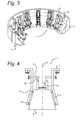
Figure 3 shows a detailed cross-sectional view of the buoy locking system of the turret mooring system according to an embodiment; -
Figure 4 shows a schematic drawing of a turret mooring system with a structural connector according to an embodiment of the invention. - In the following figures, the same reference numerals refer to similar or identical components in each of the figures.
-
Figures 1 ,2 and3 show schematic drawings of aturret mooring system 1 provided on a vessel 2 (partially shown), which for example could be a floating production unit (FPU) or floating production storage and offloading (FPSO) unit or floating storage and offloading (FSO) unit. Thevessel 2 comprises ahull 16 having amoonpool 18 extending through the hull and terminating at bottom 17 of the hull. A liftingdevice 26 is placed on theturret mooring structure 3 comprising acable 19 that extends through the center of the turret mooring system and is connected to buoy 6 for reconnection of the buoy to the turret. In an embodiment, themooring buoy 6 comprises a central shaft for leading thecable 19 through the buoy. - In addition, the
turret mooring system 1 is rotatably suspended from thehull 16 of thevessel 2. Theturret mooring system 1 comprises aturret mooring structure 3 within themoonpool 18. - A
turret bearing system 21 connects and aligns theturret mooring structure 3 with respect to thevessel 2. Theturret mooring system 1 is as a whole rotationally suspended from thevessel 2. Theturret mooring system 1 can rotate with respect to thevessel 2 to allow thevessel 2 to weathervane after connection to themooring buoy 6 or to orientate theturret mooring system 1 with respect to themooring buoy 6, without the need to reposition thevessel 2. - In addition, the
turret mooring system 1 may comprise anintermediate connection member 4. Such anintermediate connection member 4 is arranged to be rotated together with themooring buoy 6 with respect to theturret mooring structure 3, i.e. after locking themooring buoy 6 inside areceptacle 5, so that the fluid piping of the turret manifold piping and the buoy manifold piping can be aligned. Theintermediate connection member 4 is positioned in between theturret mooring structure 3 and themooring buoy 6, if present. After disconnecting themooring buoy 6, theintermediate connection member 4 remains attached to theturret mooring structure 3. - The
turret mooring structure 3 comprises thereceptacle 5 for receiving amooring buoy 6. In an alternative embodiment (not shown), thereceptacle 5 could be attached directly to theintermediate connection member 4, if present. Themooring buoy 6 carries an anchoring system 27 which may comprise at least one anchoring leg 22 that are connected to a seabed and carriesrisers 23. Themooring buoy 6 is receivable in thereceptacle 5 for coupling with theturret mooring structure 3. - The
turret mooring structure 3 comprises abuoy locking system 7, comprising a number of structural connectors (buoy locking devices) 10 for locking themooring buoy 6 inside thereceptacle 5. Thestructural connectors 10 are mounted on theconnector support structure 31 at aconnection level 30 in the turret mooring structure. - Additionally, the
structural connectors 10 each are arranged on theconnector support structure 31 with a respective base mount 34 for downward loads and abase mount 32 for upward loads which are arranged between theconnector support structure 31 and theturret mooring structure 3. - Each
base mount buoy 6 with respect to the vessel/turret. Additionally, the base mounts render the link between the turret and the buoy moveable for alignment. Due to these features, any movement of the buoy relative to the turret produces comparatively very little moment in thebuoy locking system 7 and little load in thestructural connector 10. In this manner a reduced moment connection can be established between thebuoy 6 and theturret mooring system 1, thus reducing structural connector loads. - In an embodiment, the base mounts 32 and 34 comprise elastomeric pads that provide elastic deformation to reduce moment when applied shear forces are present.
- When there is no upward loading in the system, only base mounts 34 are required.
- In an alternative embodiment, the base mounts 32 and 34 comprise spring elements that can reduce moment. In yet another embodiment, the base mounts 32 or 34 comprise one or more hydraulic actuators that can reduce or eliminate moment.
- According to the present invention the base mounts 32 and 34 are mounted on a
connector support structure 31 that connects to the outer structure of theturret mooring system 1. - In an embodiment the
connector support structure 31 is a spherical bearing. - The bearing structure can provide some angular rotation to the structural connectors to reduce the magnitude of the moment acting on the connector assembly and on the turret when movement of the buoy occurs within the turret.
- In
Fig 2 , a detailed view of onestructural connector 10 according to an embodiment is provided where the structural connector that has a base mounts 32 and 34 comprising elastomeric pads mounted on theconnector support structure 31. - The
elastomeric pads central axis 33 so that the axes normal to eachpad imaginary center 36 of the created spherical support. The angle of the axis normal to the pads from the horizontal may be 40 to 70 degrees. The angle is selected to optimize the loading within the system. - In an embodiment, radial supports 37 (radial contactors) are provided at one or two levels within the
receptacle 5 orturret 3 for contacting the outer surface of thebuoy 6. Such radial supports 37 may provide improved stability of the buoy-turret connection. - The concept of deflecting
pads connector support structure 31 and theconnectors 10 and unless they are sloped as described above, it will not be effective in reducing the loading on the connector. - According to the invention, the radial supports 37 at turret bottom of the turret are utilized to reduce the shear and moment loading on the connector by providing primary load transfer directly into the turret. The radial supports may be discrete bearing pads or may be a continuous surfaces.
- In an embodiment, the
buoy 6 is also provided withresilient pads 37 where the buoy contacts the lower end of the turret The pads could be either in contact or could have a small gap (< about 10mem). - It is noted that the
structural connector 10 with base mounts 32 and 34 according to the present invention could be utilized with a turret mooring structure comprising as theturret bearing structure 21 either a standard main roller bearing or a bogie wheel arrangement. - In a further embodiment, the
turret mooring structure 3 is provided withradial supports 37 at one or two levels below the connection level. Such an arrangement with one or two levels of radial supports where forces can be transmitted from the buoy to the outer structure through the supports may provide an enhanced load transfer mechanism. - The
turret mooring structure 3 comprises a turret manifold that can be connected to a corresponding buoy manifold to establish a fluid flow path between theturret mooring structure 3 and themooring buoy 6. - When the
mooring buoy 6 enters thereceptacle 5, themooring buoy 6 is pre-centered into thereceptacle 5, due to the conical shape andfenders 11 on the inside of thereceptacle 5 or on thebuoy 6, and due to the pulling tension in the reconnection winch cable of thelifting device 26. - When approaching the locking devices, the top ring of the buoy, lifted-up by a
lifting device 26, comes into contact vertically with the locking devices that can achieve a final centering of the buoy. When the centering is completed, the locking devices are closed and clamp the top ring of the buoy in theturret mooring structure 3. - After alignment of the fluid piping manifolds and the locking of the turret with regard to the
connected buoy 6, a fluid transfer path can be established between the turret and buoy manifold. -
Figure 4 shows a schematic drawing of a turret mooring system according to an embodiment of the invention. In this embodiment, theconnector support structure 31 has abase mount 32 comprising anhydraulic structure 35 mounted on theturret structure 3. - The
hydraulic structure 35 is fluid filled, and distributed around the central connection axis. The distribution is arranged circular round the verticalcentral axis 33 of the turret. Thehydraulic structure 36 can be embodied as a bladder (e.g. toroidal), a series of bladders or pads or a series of hydraulic cylinders. - In an embodiment, the series options are arranged with free-flowing hydraulic interconnections 38 for hydraulic fluid between the bladders or cylinders to maintain equal pressure in each of the bladders (pads) or cylinders to react the vertical load from the
buoy 6. - Below the structural connectors, load reacting mechanism comprises two
radial supports 37 to the outer structure (e.g. turret cylinder or moonpool) arranged along the circumference of theouter structure 4, to provide contact areas between theouter structure 4 and thebuoy 6. For this embodiment, the secondradial support 37 is located near the upper end of the buoy. Such radial supports 37 are capable of transmitting moments as force couples to the outer structure. - The descriptions above are intended to be illustrative, not limiting. Thus, it will be apparent to one skilled in the art that modifications may be made to the invention as described without departing from the scope of the claims set out below.
-
- 1. Turret mooring system
- 2. Vessel
- 3. Turret mooring structure
- 4. Lower turret structure
- 5. Receptacle
- 6. Mooring buoy
- 7. Buoy locking system
- 10. Structural connector (Locking device)
- 11. Fenders
- 12. Radial bearing
- 13. Upper axial bearing
- 16. Hull
- 17. Bottom of hull
- 18. Moon pool
- 19. Cable
- 21. Turret bearing system
- 22. Anchoring legs
- 23. Riser
- 26. Lifting device
- 27. Anchoring system
- 31. Connector support structure
- 32. upper base mount
- 33. vertical central axis
- 34. lower base mount
- 35. hydraulic structure
- 36. imaginary center of spherical support
- 37. radial support
- 38. hydraulic interconnection
Claims (10)
- Turret mooring system (1) arranged on a vessel for receiving a mooring buoy (6), the turret mooring system comprising a turret mooring structure (3) with a receptacle for the reception of the buoy, and at least one structural connector (10) which secures the turret to the mooring buoy which is provided with at least one buoy locking system (7) for locking the mooring buoy (6),
the buoy locking system being arranged with a base mount that connects the structural connector to the vessel, the base mount being an adjustable element for adjustment of the connection between the at least one structural connector and the vessel. - Turret mooring system according to claim 1, wherein the base mount is a ring on which the at least one structural connectors are mounted.
- Turret mooring system according to claim 1 or 2, wherein the base mount is a spherical bearing.
- Turret mooring system according to claim 1 or 2, wherein the base mount comprises pads which are arranged to form a spherical support.
- Turret mooring system according to claim 1, wherein the base mount is selected from a group connection elements comprising springs, elastomeric pad, and hydraulics.
- Turret mooring system according to claim 1 or 5, wherein the base mount comprises an hydraulic connection element, wherein the hydraulic connection element is selected from a group comprising a toroidal bladder, a series of either bladders or pads and a series of hydraulic cylinders.
- Turret mooring system according to claim 6, wherein either the bladders or the cylinders are arranged in series by hydraulic interconnections for hydraulic fluid.
- Turret mooring system according to claim 7, wherein the hydraulic interconnections for hydraulic fluid are arranged in a free-flowing mode to maintain a substantially equal pressure in each of either the bladders or the cylinders.
- Vessel comprising a hull (16) and a turret mooring system (1), wherein the turret mooring system (1) is rotatably suspended from the hull (16) of the vessel (2), the turret mooring system being in accordance with any one of the preceding claims.
- Method of mooring a vessel comprising a turret mooring system (1) to a mooring buoy (6), the turret mooring system (1) being arranged to receive the mooring buoy (6) and the turret mooring system (1) comprising a turret mooring structure (3) being rotatably suspended from the vessel (2); the method comprising:- receiving the mooring buoy (6) into the turret mooring system (1),- locking the mooring buoy (6) so as to secure the turret to the mooring buoy by at least one structural connector (10) which is provided with at least one buoy locking system (7) for locking the mooring buoy (6),- arranging the at least one buoy locking system with a base mount that connects the structural connector to the vessel, the base mount being an adjustable element for adjustment of the connection between the at least one structural connector and the vessel.
Priority Applications (6)
| Application Number | Priority Date | Filing Date | Title |
|---|---|---|---|
| EP20120165958 EP2657123A1 (en) | 2012-04-27 | 2012-04-27 | Reduced moment connection foundation |
| PCT/EP2013/058888 WO2013160483A1 (en) | 2012-04-27 | 2013-04-29 | Reduced moment connection foundation |
| US14/397,134 US20150122167A1 (en) | 2012-04-27 | 2013-04-29 | Reduced Moment Connection Foundation |
| RU2014147732A RU2014147732A (en) | 2012-04-27 | 2013-04-29 | CONNECTING BASE WITH REDUCED MOMENT |
| AU2013254639A AU2013254639A1 (en) | 2012-04-27 | 2013-04-29 | Reduced moment connection foundation |
| CA 2871548 CA2871548A1 (en) | 2012-04-27 | 2013-04-29 | Reduced moment connection foundation |
Applications Claiming Priority (1)
| Application Number | Priority Date | Filing Date | Title |
|---|---|---|---|
| EP20120165958 EP2657123A1 (en) | 2012-04-27 | 2012-04-27 | Reduced moment connection foundation |
Publications (1)
| Publication Number | Publication Date |
|---|---|
| EP2657123A1 true EP2657123A1 (en) | 2013-10-30 |
Family
ID=48289136
Family Applications (1)
| Application Number | Title | Priority Date | Filing Date |
|---|---|---|---|
| EP20120165958 Withdrawn EP2657123A1 (en) | 2012-04-27 | 2012-04-27 | Reduced moment connection foundation |
Country Status (6)
| Country | Link |
|---|---|
| US (1) | US20150122167A1 (en) |
| EP (1) | EP2657123A1 (en) |
| AU (1) | AU2013254639A1 (en) |
| CA (1) | CA2871548A1 (en) |
| RU (1) | RU2014147732A (en) |
| WO (1) | WO2013160483A1 (en) |
Families Citing this family (2)
| Publication number | Priority date | Publication date | Assignee | Title |
|---|---|---|---|---|
| CA3019693A1 (en) * | 2016-04-06 | 2017-10-12 | Single Buoy Moorings Inc. | Turret mooring system arrangement |
| CN111907646B (en) * | 2020-08-06 | 2021-05-11 | 友联船厂(蛇口)有限公司 | Turret of FPSO floating production storage and offloading oil tanker based on guide rail design |
Citations (7)
| Publication number | Priority date | Publication date | Assignee | Title |
|---|---|---|---|---|
| US5240446A (en) | 1991-09-27 | 1993-08-31 | Sofec, Inc. | Disconnectable mooring system |
| US5380229A (en) | 1992-12-31 | 1995-01-10 | Korsgaard; Jens | Vessel mooring system and vessel equipped for the system |
| US5515804A (en) | 1995-08-21 | 1996-05-14 | Imodco, Inc. | Bearing support for single point terminal |
| US5957076A (en) * | 1997-08-15 | 1999-09-28 | Imodco, Inc. | Offshore turret upper bearing |
| WO2007077126A1 (en) | 2006-01-03 | 2007-07-12 | Bluewater Energy Services B.V. | Disconnectable mooring system for a vessel |
| WO2010106132A2 (en) | 2009-03-18 | 2010-09-23 | Single Buoy Moorings Inc. | Disconnectable mooring buoy with enhanced hydraulic coupling and latch |
| WO2012035154A1 (en) * | 2010-09-16 | 2012-03-22 | Single Buoy Moorings Inc. | Disconnectable turret mooring system |
Family Cites Families (2)
| Publication number | Priority date | Publication date | Assignee | Title |
|---|---|---|---|---|
| US5356321A (en) * | 1991-09-27 | 1994-10-18 | Sofec, Inc. | Disconnectable mooring system |
| WO2008086225A2 (en) * | 2007-01-05 | 2008-07-17 | Sofec, Inc. | Detachable mooring and fluid transfer system |
-
2012
- 2012-04-27 EP EP20120165958 patent/EP2657123A1/en not_active Withdrawn
-
2013
- 2013-04-29 RU RU2014147732A patent/RU2014147732A/en not_active Application Discontinuation
- 2013-04-29 CA CA 2871548 patent/CA2871548A1/en not_active Abandoned
- 2013-04-29 AU AU2013254639A patent/AU2013254639A1/en not_active Abandoned
- 2013-04-29 WO PCT/EP2013/058888 patent/WO2013160483A1/en not_active Ceased
- 2013-04-29 US US14/397,134 patent/US20150122167A1/en not_active Abandoned
Patent Citations (7)
| Publication number | Priority date | Publication date | Assignee | Title |
|---|---|---|---|---|
| US5240446A (en) | 1991-09-27 | 1993-08-31 | Sofec, Inc. | Disconnectable mooring system |
| US5380229A (en) | 1992-12-31 | 1995-01-10 | Korsgaard; Jens | Vessel mooring system and vessel equipped for the system |
| US5515804A (en) | 1995-08-21 | 1996-05-14 | Imodco, Inc. | Bearing support for single point terminal |
| US5957076A (en) * | 1997-08-15 | 1999-09-28 | Imodco, Inc. | Offshore turret upper bearing |
| WO2007077126A1 (en) | 2006-01-03 | 2007-07-12 | Bluewater Energy Services B.V. | Disconnectable mooring system for a vessel |
| WO2010106132A2 (en) | 2009-03-18 | 2010-09-23 | Single Buoy Moorings Inc. | Disconnectable mooring buoy with enhanced hydraulic coupling and latch |
| WO2012035154A1 (en) * | 2010-09-16 | 2012-03-22 | Single Buoy Moorings Inc. | Disconnectable turret mooring system |
Also Published As
| Publication number | Publication date |
|---|---|
| AU2013254639A1 (en) | 2014-11-27 |
| CA2871548A1 (en) | 2013-10-31 |
| WO2013160483A1 (en) | 2013-10-31 |
| US20150122167A1 (en) | 2015-05-07 |
| RU2014147732A (en) | 2016-06-20 |
Similar Documents
| Publication | Publication Date | Title |
|---|---|---|
| EP2303680B1 (en) | Disconnectable turret mooring system with optional rotation between turret and manifold | |
| EP2408661B1 (en) | Mooring system with decoupled mooring lines and/or riser system | |
| CN108473182B (en) | Detachable fork arm assembly for tower and using method thereof | |
| US8418639B2 (en) | Mooring system for a vessel | |
| US9221523B2 (en) | Disconnectable turret mooring system | |
| US20150122167A1 (en) | Reduced Moment Connection Foundation | |
| EP2807077B1 (en) | Disconnectable turret mooring system | |
| US9963205B2 (en) | Disconnectable submerged buoy mooring device comprising clamping dogs | |
| AU2012200596B2 (en) | A mooring system for a vessel and a method of mooring a vessel | |
| AU2015200739A1 (en) | Mooring system with decoupled mooring lines and/or riser system | |
| GB2484031A (en) | A mooring system for a vessel and a method of mooring a vessel |
Legal Events
| Date | Code | Title | Description |
|---|---|---|---|
| PUAI | Public reference made under article 153(3) epc to a published international application that has entered the european phase |
Free format text: ORIGINAL CODE: 0009012 |
|
| AK | Designated contracting states |
Kind code of ref document: A1 Designated state(s): AL AT BE BG CH CY CZ DE DK EE ES FI FR GB GR HR HU IE IS IT LI LT LU LV MC MK MT NL NO PL PT RO RS SE SI SK SM TR |
|
| AX | Request for extension of the european patent |
Extension state: BA ME |
|
| STAA | Information on the status of an ep patent application or granted ep patent |
Free format text: STATUS: THE APPLICATION IS DEEMED TO BE WITHDRAWN |
|
| 18D | Application deemed to be withdrawn |
Effective date: 20140501 |