EP2657039A1 - Printer and platen roller for printer - Google Patents
Printer and platen roller for printer Download PDFInfo
- Publication number
- EP2657039A1 EP2657039A1 EP11851240.9A EP11851240A EP2657039A1 EP 2657039 A1 EP2657039 A1 EP 2657039A1 EP 11851240 A EP11851240 A EP 11851240A EP 2657039 A1 EP2657039 A1 EP 2657039A1
- Authority
- EP
- European Patent Office
- Prior art keywords
- roller
- sheet
- platen roller
- print paper
- gap
- Prior art date
- Legal status (The legal status is an assumption and is not a legal conclusion. Google has not performed a legal analysis and makes no representation as to the accuracy of the status listed.)
- Granted
Links
Images



Classifications
-
- B—PERFORMING OPERATIONS; TRANSPORTING
- B41—PRINTING; LINING MACHINES; TYPEWRITERS; STAMPS
- B41J—TYPEWRITERS; SELECTIVE PRINTING MECHANISMS, i.e. MECHANISMS PRINTING OTHERWISE THAN FROM A FORME; CORRECTION OF TYPOGRAPHICAL ERRORS
- B41J13/00—Devices or arrangements of selective printing mechanisms, e.g. ink-jet printers or thermal printers, specially adapted for supporting or handling copy material in short lengths, e.g. sheets
- B41J13/02—Rollers
- B41J13/025—Special roller holding or lifting means, e.g. for temporarily raising one roller of a pair of nipping rollers for inserting printing material
-
- B—PERFORMING OPERATIONS; TRANSPORTING
- B41—PRINTING; LINING MACHINES; TYPEWRITERS; STAMPS
- B41J—TYPEWRITERS; SELECTIVE PRINTING MECHANISMS, i.e. MECHANISMS PRINTING OTHERWISE THAN FROM A FORME; CORRECTION OF TYPOGRAPHICAL ERRORS
- B41J11/00—Devices or arrangements of selective printing mechanisms, e.g. ink-jet printers or thermal printers, for supporting or handling copy material in sheet or web form
- B41J11/02—Platens
- B41J11/04—Roller platens
-
- B—PERFORMING OPERATIONS; TRANSPORTING
- B41—PRINTING; LINING MACHINES; TYPEWRITERS; STAMPS
- B41J—TYPEWRITERS; SELECTIVE PRINTING MECHANISMS, i.e. MECHANISMS PRINTING OTHERWISE THAN FROM A FORME; CORRECTION OF TYPOGRAPHICAL ERRORS
- B41J11/00—Devices or arrangements of selective printing mechanisms, e.g. ink-jet printers or thermal printers, for supporting or handling copy material in sheet or web form
- B41J11/02—Platens
- B41J11/04—Roller platens
- B41J11/057—Structure of the surface
-
- B—PERFORMING OPERATIONS; TRANSPORTING
- B41—PRINTING; LINING MACHINES; TYPEWRITERS; STAMPS
- B41J—TYPEWRITERS; SELECTIVE PRINTING MECHANISMS, i.e. MECHANISMS PRINTING OTHERWISE THAN FROM A FORME; CORRECTION OF TYPOGRAPHICAL ERRORS
- B41J2/00—Typewriters or selective printing mechanisms characterised by the printing or marking process for which they are designed
- B41J2/315—Typewriters or selective printing mechanisms characterised by the printing or marking process for which they are designed characterised by selective application of heat to a heat sensitive printing or impression-transfer material
- B41J2/32—Typewriters or selective printing mechanisms characterised by the printing or marking process for which they are designed characterised by selective application of heat to a heat sensitive printing or impression-transfer material using thermal heads
-
- B—PERFORMING OPERATIONS; TRANSPORTING
- B41—PRINTING; LINING MACHINES; TYPEWRITERS; STAMPS
- B41J—TYPEWRITERS; SELECTIVE PRINTING MECHANISMS, i.e. MECHANISMS PRINTING OTHERWISE THAN FROM A FORME; CORRECTION OF TYPOGRAPHICAL ERRORS
- B41J3/00—Typewriters or selective printing or marking mechanisms characterised by the purpose for which they are constructed
- B41J3/60—Typewriters or selective printing or marking mechanisms characterised by the purpose for which they are constructed for printing on both faces of the printing material
Definitions
- the present invention relates to a printer a printer and a platen roller, and more particularly to a printer and a platen roller for applying appropriate printing pressure to a print paper.
- a double-sided label continuum with no backing sheet which is made by laminating a first sheet and a second sheet.
- an adhesive and a remover are formed alternately at positions, where the adhesive of a sheet attaches temporarily to the remover of another sheet.
- Figure 7 is a cross-sectional view of a double-sided label continuum in a direction perpendicular to a feeding direction, where the double-sided label continuum L having adhesives 52 being arranged with a predetermined gap 58 is clamped with pressure between a platen roller 59 and a thermal head 60, and is printed and fed.
- the double-sided label continuum L is composed of a first sheet 50, a second sheet 51, an adhesive 52, and a remover 53.
- the first sheet 50 is composed of a first coloring layer 54 and a first base material 55, and a back side surface of the first coloring layer 54 and a front surface of the first base material 55 are bonded.
- the second sheet 51 is composed of a second coloring layer 56 and a second base material 57, and a back side surface of the second coloring layer 56 and a front surface of the second base material 57 are bonded as well the first sheet 50.
- an adhesive 52 and a remover 53 are applied alternately, linearly parallel to the feeding direction, such that the adhesive 52 of a sheet adheres temporarily to the remover 53 of another sheet.
- a width G of the adhesive 52 which is perpendicular to the coating direction thereof is set smaller than a width of the remover 53.
- the adhesive 52 and the remover 53 are attached temporarily, they are arrayed through a gap 58 having a width H perpendicular to the coating direction of the adhesive 52. Because a coating thickness of the adhesive 52 is thicker than a coating thickness of the remover 53, the adhesive 52 does not bond to the neighboring adhesives 52, even if the adhesive 52 spreads by the pressure applied between the platen roller 59 and the thermal head 60.
- An object of the present invention is to provide a printer and a printer platen roller which are arranged to grant an appropriate pressure suitable for printing to a printing paper being made by laminating a first sheet and a second sheet through a gap, by filling the gap.
- the present invention relates to having a platen roller provided with a projecting portion protruding outward in a radial direction of a body roller.
- a point of a first invention relates to a printer, comprising a feed section capable of feeding a print paper having a first sheet and a second sheet laminated to the first sheet through a gap, and a print section for printing the print paper, wherein the print section comprises a thermal head and a platen roller being opposed to the thermal head, wherein the platen roller comprises an shaft being rotatably supported in a direction perpendicular to a feeding direction of the print paper, a cylindrical body roller disposed to the shaft, and a projecting portion protruding outward in a radial direction of the body roller for filling the gap by pressing the print paper.
- the print section comprises a first thermal head being located upstream in a feeding direction of the print paper for printing a first surface of the print paper, a first platen roller being opposed to the first thermal head, a second thermal head being located at downstream in the feeding direction of the print paper for printing a second surface of the print paper, and a second platen roller being opposed to the second thermal head.
- the platen roller comprises the shaft being rotatably supported in the direction perpendicular to the feeding direction of the print paper, a plurality of cylindrical body rollers disposed to the shaft, and a projecting roller being located between the body rollers and protruding outward in a radial direction of the body rollers for filling the gap by pressing the print paper.
- a point of a second invention relates to a printer platen roller for clamping and feeding a print paper having a first sheet and a second sheet laminated to the first sheet through a gap by pressing the print paper to a thermal head, comprising an shaft rotatably supported in a direction to a feeding direction of the print paper;, a cylindrical body roller disposed to the shaft;, and a projecting portion protruding outward in a radial direction of the body roller for filling the gap substantially by pressing the print paper.
- the printer and the printer platen roller of the present invention when printing is made on a print paper having a first sheet and a second sheet laminated to the first sheet through a gap, it becomes possible to give appropriate pressure necessary for printing uniformly to the print paper with a simple configuration of only a structure of the platen roller, without using any expensive and complicated equipment such as a controller, etc.
- the printer of the first invention in particular, it is possible to keep a print quality at a predetermined level.
- the printer platen roller of the second invention in particular, it is possible to deal with a print paper having a different gap dimension, etc., by a simple operation.
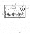
- Figure 1 is a side view of a double-sided label printer 1 according to the example 1 of the present invention.
- the double-sided label printer 1 is composed of a label supply section 2, a label feed section 3, a label detection section 4, a label print section 5, a label cut section 6, and a control section 7.
- the label supply section 2 is configured so as to mount a rolled double-sided label continuum L to a label supply reel 8, and to supply the double-sided label continuum L to the label feed section 3.
- the label feed section 3 is composed of a guide roller 9, a label width regulating guide 10, a driven roller 11, and a drive roller 12.
- the guide roller 9 is disposed rotatably at an upstream position of the label print section 5, and guides the label continuum without a backing paper so as to be fed to the label print section 5.
- the label width regulating guide 10 is located between the guide roller 9, and the driven roller 11 and the drive roller 12.
- the drive roller 12 and the driven roller 11 are opposed to each other on an upstream side of the label print section 5, and on a downstream side of the label width regulating guide 10, so as to clamp and feed the label continuum L without a backing paper to the label print section 5 while preventing generation of serpentine and slack.
- One end of the shaft of the drive roller 12 is connected to a motor (not shown) through a belt, and is configured to pivot to either the feeding direction or the opposite direction by a force transmitted from a drive source.
- the label width regulating guide 10, the driven roller 11 and the drive roller 12 may be located between a label detection section 4 and a first print section 15, or between a first print section 15 and a second print section 16, so that each of the plurality of projecting portions 32 of a first platen roller 17 and a second platen roller 19 mate with a corresponding gap 58 without a shift.
- a label detection section 4 is composed of a light emitter 13 and a light receiver 14.
- the light emitter 13 and the light receiver 14 are located on the upstream side of the label print section 5, and on the downstream side of the label feed section 3, and in a back surface side of the double-sided label continuum L.
- marks On the back surface of the double-sided label continuum L, marks (not shown) that reflects a light emitted from the light emitter 13 are printed at equal intervals.
- the label detection section 4 detects a position and a feeding amount of the double-sided label continuum L, by emitting a light from the light emitter 13 to the back surface of the and double-sided label continuum L and receiving the light reflected from the marks at the light receiver 14.
- a label print section 5 is composed of a first print section 15, and a second print section 16.
- the first print section 15 is composed of a first platen roller 17 and a first thermal head 18.
- the first platen roller 17 being opposed to the back surface side of the double-sided label continuum L and the first thermal head 18 being opposed to the front surface side of the double-sided label continuum L clamp the double-sided label continuum L by a predetermined pressing force and conducts printing on the surface of the double-sided label continuum L and feed the printed one.
- the second print section 16 is composed of a second platen roller 19 and a second thermal head 20.
- the second platen roller 19 being opposed to the front surface side of the double-sided label continuum L and the second thermal head 20 being opposed to the back surface side of the double-sided label continuum L clamp the double-sided label continuum L by a predetermined pressing force and conducts printing on the surface of the double-sided label continuum L and feed the printed one to a label cut section 6.
- the label cut section 6 comprises an upper cutter 21 and a lower cutter 22.
- the upper cutter 21 and the lower cutter 22 are opposed on a downstream side of the label print section 5, so that a blade of the upper cutter 21 mates with a blade of the lower cutter 22.
- the double-sided label continuum L is clamped between the upper cutter 21 and the lower cutter 22, and is cut by driving the lower cutter 22.
- a control section 7 comprises CPU, ROM, RAM, etc. (not shown), and is connected to the above mentioned sections 2, 3, 4 through a data bus (not shown), and controls the operation of each section.
- Figure 2 is a front view of the first platen roller 17 according to the example 1 of the present invention.
- the second platen roller 19 has a configuration similar to that of the first platen roller 17, and so descriptions thereof shall be omitted.
- An shaft 30 has a cylindrical rod shape and is made of a metal such as a stainless steel.
- the shape is not limited to the cylindrical rod shape.
- a cylindrical tube shape or the like is possible.
- a resin can be used, not limited to a metal.
- Both ends of the shaft are pivotally supported by the bearing (not shown) of the double-sided label printer 1 so as to be opposed to the thermal head 18.
- One end of the shaft is connected to a motor (not shown) through a belt, and is configured to pivot to either the feeding direction or the opposite direction by a force transmitted from a drive source,
- a body roller 31 has an empty central axis and is made of an elastic body such as an urethane rubber, a silicone rubber, etc..
- the shaft 30 is inserted into the empty central axis and fixed. When the shaft 30 is rotationally driven, the body roller 31 is also rotationally driven together.
- a plurality of projecting portions 32 are provided at a predetermined interval along the periphery of the body roller as shown.
- a rectangular shape cross section in the axis direction protrudes outward in a radial direction.
- the axis direction cross-sectional shape of the projecting portions 32 is not limited to the rectangular shape.
- a circular shape, an elliptical shape or the like can be used, for example.
- a predetermined interval length 'A' in the shaft 30 direction between the plurality of the projecting portions 32 corresponds to a width 'G' of an adhesive 52.
- the adhesive 52 it is desirable for the adhesive 52 to have a length enough for rolling up the remover 53, in addition to 'G'.
- a length 'B' of the projecting portion 32 in the shaft 30 direction corresponds to a width 'H' of a gap of the double-sided label continuum L.
- the length 'B' it is desirable for the length 'B' to have a length shorter than 'H', and have a length enough for applying an appropriate pressure to a first coloring layer 54.
- a length 'C' protruding outward in a radial direction as shown in Figure 3 corresponds to a thickness 'c' of the adhesive 52.
- the double-sided label printer 1 has the above described configuration.
- the double-sided label continuum L is supplied by the label supply section 2, the width of the supplied double-sided label continuum L is regulated by the width regulating guide 12 of the label feed section 3, and further the double-sided label continuum L is fed to the label print section 5 while being prevented from serpentine and skewing by being pressure clamped between the driven roller 11 and the drive roller 12.
- the double-sided label continuum L fed to the label print section 5 is pressure clamped between the first platen roller 17 and the first thermal head 18 being pressed by the press spring 33, at the first print sectionl5, as shown in Figure 4 .
- the projecting portion 32 presses the second sheet 51 to the gap 58 direction so that the second sheet 51 protrudes toward the gap 58, and the gap 58 of the double-sided label continuum L is filled.
- the first coloring layer 54 is pressed with an appropriate pressure for printing, receives heat at a contact point of a heating element of the thermal head 18 and the coloring layer 54, and a set information is printed at a predetermined set position.
- the double-sided label continuum L is fed to the second print section 16 and is pressure clamped between the second platen roller 19 and the second thermal head 20, and then a printing is made to the second coloring layer 56 in the same manner as that at the above-described first print section 15.
- the upper cutter 21 and the lower cutter 22 are driven at the label cut section 6, and the double-sided label continuum L is cut at a set position.
- the gap 58 is filled, and an appropriate pressure for printing can be applied, by pressing the projecting portion 32 provided along the periphery of the platen roller 17 to another sheet (the second sheet 51).
- the shaft 30 direction length 'A' of the interval between each of the plurality of the projecting portions 32 is set to be longer than the shaft 30 direction length 'G' of the adhesive 52, and the shaft 30 direction width 'B' of the projecting portions 32 is set to a length to the extent so that an appropriate printing pressure is applied, and to be shorter than the shaft 30 direction width 'H' of the gap 58.
- the protruding length 'C' of another sheet substantially coincides with the thickness 'I' of the adhesive 52, and a uniform pressure can be applied to the coloring layer to be printed. Further, only by providing the platen roller 17 with the projecting portion 32, an appropriate pressure for printing can be applied and a printing accuracy can be maintained at a predetermined level, without using an expensive controller or the like which needs a space.
- the length 'C' protruding in a radial direction of the projecting portion 32 is set to be substantially the same as the thickness 'I' of the adhesive 52, the length 'C' can be changed appropriately, depending on an elastic modulus, etc., of the adhesive, since it is enough to apply substantially the same pressure as that at the pressed portion by the body roller 42, when the double-sided label continuum L is pressure clamped between the platen roller 40 and the thermal head 18 and is printed.
- first platen roller 40 according to the example 2 shall be described with reference to Figures 5 and 6 .
- Description of the second platen roller (not shown) having the same configuration as that of the first platen roller 40 shall be omitted.
- the similar portions as those in the example 1 only the same reference sign shall be assigned, and duplicated description shall be omitted.
- Figure 5 is a front view of the first platen roller 40 according to the example 2.
- the first platen roller 40 is composed of a shaft 41, a body roller 42 and a projecting roller 43.
- the shaft 41 has the same configuration as that of the shaft 30, and so description is omitted.
- the body roller 42 has an empty central axis and is made of an elastic body such as an urethane rubber, a silicone rubber, etc..
- the shaft 41 is inserted into the empty central axis at a predetermined interval and is fixed.
- the body roller 42 is also rotationally driven together.
- a length 'D' of the body roller 42 in the shaft 42 direction corresponds to a width 'G' of the adhesive 52. Because a remover 53 is rolled up in an adhesive 52 direction in a process when a projecting roller 32 presses a second sheet 51 and a gap 58 is filled, it is desirable for the length 'D' to have a length enough for winding up the remover 53 in addition to the width 'G'.
- the projecting roller 43 has an empty central axis and is made of an elastic body.
- the shaft 41 is inserted into the empty central axis through the body roller 42 and is fixed.
- the projecting roller 43 is also rotationally driven together.
- a length 'E' of the projecting roller 43 in the shaft 41 direction corresponds to a width 'H' of a gap of the double-sided label continuum L.
- the length 'E' it is desirable for the length 'E' to have a length shorter than 'H', and have a length enough for applying an appropriate pressure to a first coloring layer 54.
- a length 'F' of the projecting roller 43 protruding outward in the radial direction corresponds to a thickness 'I' of the adhesive 52 when the double-sided label continuum L is pressure clamped between the first platen roller 40 and the first thermal head 18 at printing. It is desirable for the length 'F' to have substantially the same length as 'I', in order to apply a uniform pressure to a coloring layer 54.
- the first platen roller 40 according to the example 2 has the above described configuration. As shown in Figure 6 , by the process in which the platen roller 40 presses the double-sided label continuum L, the projecting roller 43 protrudes so that the second sheet 51 enters into the gap 58, and the gap 58 is filled, and an appropriate pressure for printing is applied to the coloring layer 54 almost uniformly, and printing is performed with high precision.
- the gap 58 is filled, and an appropriate pressure for printing can be applied, by pressing the first platen roller 40 to the non-printing sheet (the second sheet 51) so that the second sheet 51 protrudes toward the gap 58.
- the length 'F' protruding outward in a radial direction of the projecting roller 43 is substantially the same as the thickness 'I' of the adhesive 52 being pressure clamped at printing, about the same pressure as the pressure applied to the portion which is pressed through the adhesive 52 can be granted to the portion of the first coloring layer 54 which is pressed through the gap 58. Further, even if the projecting roller 43 is damaged by abrasion or the like, only the damaged projecting roller 43 should be replaced, and so the cost can be reduced and the work efficiency can be increased.
- double-sided label continuums L having different dimension or the like of the gap, the adhesive, and the remover of the double-sided label continuum L
- the length 'F' protruding outward in a radial direction of the projecting roller 43 is set to be substantially the same as the thickness of the adhesive 52, it is not particularly applicable in a case where the body roller 42 and the projecting roller 43 have different elastic modulus, since it is enough to apply substantially the same pressure as that at the pressed portion by the body roller 42, when the double-sided label continuum L is pressure clamped between the platen roller 40 and the thermal head 18 and is printed.
- a number, a position, a shape or the like of each composing member is not limited to the embodiment described above.
- the number, the position, the shape or the like can be set to be suitable for carrying out the present invention. It is apparent the present invention is not limited to each of the above described embodiments, and the embodiment can be modified appropriately within the scope of the technical concept of the present invention.
Landscapes
- Handling Of Sheets (AREA)
- Electronic Switches (AREA)
Abstract
Description
- The present invention relates to a printer a printer and a platen roller, and more particularly to a printer and a platen roller for applying appropriate printing pressure to a print paper.
- Conventionally, a double-sided label continuum with no backing sheet is known, which is made by laminating a first sheet and a second sheet. On each back side surface of the first sheet and the second sheet, an adhesive and a remover are formed alternately at positions, where the adhesive of a sheet attaches temporarily to the remover of another sheet.
- When the double-sided label continuum without the backing sheet as described above is clamped with pressure between a platen roller and a thermal head and is printed, the adhesive spreads by the pressure. As a result, there generates a problem such that the adhesive attaches to the neighboring adhesives or another sheet, or the adhesive protrudes from the outer edge of the label. In order to prevent such problems, a double-sided label continuum is used in which a gap is provided respectively between neighboring adhesives.
-
Figure 7 is a cross-sectional view of a double-sided label continuum in a direction perpendicular to a feeding direction, where the double-sided label continuumL having adhesives 52 being arranged with apredetermined gap 58 is clamped with pressure between aplaten roller 59 and athermal head 60, and is printed and fed. The double-sided label continuum L is composed of afirst sheet 50, asecond sheet 51, an adhesive 52, and aremover 53. Thefirst sheet 50 is composed of afirst coloring layer 54 and afirst base material 55, and a back side surface of thefirst coloring layer 54 and a front surface of thefirst base material 55 are bonded. Thesecond sheet 51 is composed of asecond coloring layer 56 and asecond base material 57, and a back side surface of thesecond coloring layer 56 and a front surface of thesecond base material 57 are bonded as well thefirst sheet 50. On the back side surfaces of thesecond base material 57 and thefirst base material 55, an adhesive 52 and aremover 53 are applied alternately, linearly parallel to the feeding direction, such that theadhesive 52 of a sheet adheres temporarily to theremover 53 of another sheet. A width G of theadhesive 52 which is perpendicular to the coating direction thereof is set smaller than a width of theremover 53. When theadhesive 52 and theremover 53 are attached temporarily, they are arrayed through agap 58 having a width H perpendicular to the coating direction of theadhesive 52. Because a coating thickness of theadhesive 52 is thicker than a coating thickness of theremover 53, theadhesive 52 does not bond to the neighboringadhesives 52, even if theadhesive 52 spreads by the pressure applied between theplaten roller 59 and thethermal head 60. - However, when printing is made on the double-sided label continuum having the above described
gap 58, there generates a problem that a printing precision decreases, because appropriate pressure necessary for printing is not applied to a portion of the coloring layer which is pressed to theplaten roller 59 through thegap 58 and performs printing, the heat generation of thethermal head 60 is not transmitted to the coloring layer, and so printing is not made in the part. -
- Patent literature 1: Japanese Laid-Open Patent Application Publication No.
2005-272623 - The present invention has been made in view of the above described problem. An object of the present invention is to provide a printer and a printer platen roller which are arranged to grant an appropriate pressure suitable for printing to a printing paper being made by laminating a first sheet and a second sheet through a gap, by filling the gap.
- The present invention relates to having a platen roller provided with a projecting portion protruding outward in a radial direction of a body roller. A point of a first invention relates to a printer, comprising a feed section capable of feeding a print paper having a first sheet and a second sheet laminated to the first sheet through a gap, and a print section for printing the print paper, wherein the print section comprises a thermal head and a platen roller being opposed to the thermal head, wherein the platen roller comprises an shaft being rotatably supported in a direction perpendicular to a feeding direction of the print paper, a cylindrical body roller disposed to the shaft, and a projecting portion protruding outward in a radial direction of the body roller for filling the gap by pressing the print paper. Further, such a configuration may be taken where the print section comprises a first thermal head being located upstream in a feeding direction of the print paper for printing a first surface of the print paper, a first platen roller being opposed to the first thermal head, a second thermal head being located at downstream in the feeding direction of the print paper for printing a second surface of the print paper, and a second platen roller being opposed to the second thermal head. Further, a configuration may be taken where the platen roller comprises the shaft being rotatably supported in the direction perpendicular to the feeding direction of the print paper, a plurality of cylindrical body rollers disposed to the shaft, and a projecting roller being located between the body rollers and protruding outward in a radial direction of the body rollers for filling the gap by pressing the print paper. A point of a second invention relates to a printer platen roller for clamping and feeding a print paper having a first sheet and a second sheet laminated to the first sheet through a gap by pressing the print paper to a thermal head, comprising an shaft rotatably supported in a direction to a feeding direction of the print paper;, a cylindrical body roller disposed to the shaft;, and a projecting portion protruding outward in a radial direction of the body roller for filling the gap substantially by pressing the print paper.
- According to the printer and the printer platen roller of the present invention, when printing is made on a print paper having a first sheet and a second sheet laminated to the first sheet through a gap, it becomes possible to give appropriate pressure necessary for printing uniformly to the print paper with a simple configuration of only a structure of the platen roller, without using any expensive and complicated equipment such as a controller, etc. According to the printer of the first invention in particular, it is possible to keep a print quality at a predetermined level. According to the printer platen roller of the second invention in particular, it is possible to deal with a print paper having a different gap dimension, etc., by a simple operation.
-
- [
Fig. 1] Fig. 1 is a side view of a double-sided label printer 1, where a printer according to an example 1 of the present invention is applied. - [
Fig. 2] Fig. 2 is a front view of a first platen roller17 inFigure 1 where the printer according to the example 1 of the present invention is applied. - [
Fig. 3] Fig. 3 is a cross-sectional view taken along a line II-II inFigure 1 , where the printer according to the example 1 of the present invention is applied. - [
Fig. 4] Fig. 4 is a cross-sectional view taken along a line I-I inFigure 1 when afirst platen roller 17 ofFigure 1 is pressed to athermal head 20, where the printer according to the example 1 of the present invention is applied. - [
Fig. 5] Fig. 5 is a front view of afirst platen roller 40 of an example 2 of the present invention. - [
Fig. 6] Fig. 6 is a front view of thefirst platen roller 40 of the example 2 of the present invention when thefirst platen roller 40 is pressed to a firstthermal head 18. - [
Fig. 7] Fig. 7 is a cross-sectional view of a conventional double-sided label continuum L having agap 58 when aplaten roller 59 is pressed to athermal head 60. - The example 1 shall be described with reference to
Figures 1 to 4 . In addition, in the followings, with regard to the same portions as those in the conventional art, only the same signs are assigned and duplicated descriptions are omitted. -
Figure 1 is a side view of a double-sided label printer 1 according to the example 1 of the present invention. As shown in the Figure, the double-sided label printer 1 is composed of alabel supply section 2, alabel feed section 3, alabel detection section 4, alabel print section 5, alabel cut section 6, and acontrol section 7. - The
label supply section 2 is configured so as to mount a rolled double-sided label continuum L to alabel supply reel 8, and to supply the double-sided label continuum L to thelabel feed section 3. - The
label feed section 3 is composed of aguide roller 9, a labelwidth regulating guide 10, a drivenroller 11, and adrive roller 12. Theguide roller 9 is disposed rotatably at an upstream position of thelabel print section 5, and guides the label continuum without a backing paper so as to be fed to thelabel print section 5. The labelwidth regulating guide 10 is located between theguide roller 9, and the drivenroller 11 and thedrive roller 12. By regulating the width of the double-sided label continuum L, each of a plurality of projectingportions 32 of afirst platen roller 17 to be described later, feed the double-sided label L to thelabel print section 5 so as to mate with acorresponding gap 58 without causing serpentine. Thedrive roller 12 and the drivenroller 11 are opposed to each other on an upstream side of thelabel print section 5, and on a downstream side of the labelwidth regulating guide 10, so as to clamp and feed the label continuum L without a backing paper to thelabel print section 5 while preventing generation of serpentine and slack. One end of the shaft of thedrive roller 12 is connected to a motor (not shown) through a belt, and is configured to pivot to either the feeding direction or the opposite direction by a force transmitted from a drive source. In addition, the labelwidth regulating guide 10, the drivenroller 11 and thedrive roller 12 may be located between alabel detection section 4 and afirst print section 15, or between afirst print section 15 and asecond print section 16, so that each of the plurality of projectingportions 32 of afirst platen roller 17 and asecond platen roller 19 mate with acorresponding gap 58 without a shift. - A
label detection section 4 is composed of alight emitter 13 and alight receiver 14. Thelight emitter 13 and thelight receiver 14 are located on the upstream side of thelabel print section 5, and on the downstream side of thelabel feed section 3, and in a back surface side of the double-sided label continuum L. On the back surface of the double-sided label continuum L, marks (not shown) that reflects a light emitted from thelight emitter 13 are printed at equal intervals. Thelabel detection section 4 detects a position and a feeding amount of the double-sided label continuum L, by emitting a light from thelight emitter 13 to the back surface of the and double-sided label continuum L and receiving the light reflected from the marks at thelight receiver 14. - A
label print section 5 is composed of afirst print section 15, and asecond print section 16. Thefirst print section 15 is composed of afirst platen roller 17 and a firstthermal head 18. Thefirst platen roller 17 being opposed to the back surface side of the double-sided label continuum L and the firstthermal head 18 being opposed to the front surface side of the double-sided label continuum L clamp the double-sided label continuum L by a predetermined pressing force and conducts printing on the surface of the double-sided label continuum L and feed the printed one. Thesecond print section 16 is composed of asecond platen roller 19 and a secondthermal head 20. Thesecond platen roller 19 being opposed to the front surface side of the double-sided label continuum L and the secondthermal head 20 being opposed to the back surface side of the double-sided label continuum L clamp the double-sided label continuum L by a predetermined pressing force and conducts printing on the surface of the double-sided label continuum L and feed the printed one to alabel cut section 6. - The label cut
section 6 comprises anupper cutter 21 and alower cutter 22. Theupper cutter 21 and thelower cutter 22 are opposed on a downstream side of thelabel print section 5, so that a blade of theupper cutter 21 mates with a blade of thelower cutter 22. The double-sided label continuum L is clamped between theupper cutter 21 and thelower cutter 22, and is cut by driving thelower cutter 22. - A
control section 7 comprises CPU, ROM, RAM, etc. (not shown), and is connected to the above mentionedsections - Next, the
first platen roller 17 and thesecond platen roller 19 are described in detail.Figure 2 is a front view of thefirst platen roller 17 according to the example 1 of the present invention. Thesecond platen roller 19 has a configuration similar to that of thefirst platen roller 17, and so descriptions thereof shall be omitted. - An
shaft 30 has a cylindrical rod shape and is made of a metal such as a stainless steel. The shape is not limited to the cylindrical rod shape. A cylindrical tube shape or the like is possible. With regard to the material, a resin can be used, not limited to a metal. Both ends of the shaft are pivotally supported by the bearing (not shown) of the double-sided label printer 1 so as to be opposed to thethermal head 18. One end of the shaft is connected to a motor (not shown) through a belt, and is configured to pivot to either the feeding direction or the opposite direction by a force transmitted from a drive source, - A
body roller 31 has an empty central axis and is made of an elastic body such as an urethane rubber, a silicone rubber, etc.. Theshaft 30 is inserted into the empty central axis and fixed. When theshaft 30 is rotationally driven, thebody roller 31 is also rotationally driven together. - A plurality of projecting
portions 32 are provided at a predetermined interval along the periphery of the body roller as shown. A rectangular shape cross section in the axis direction protrudes outward in a radial direction. The axis direction cross-sectional shape of the projectingportions 32 is not limited to the rectangular shape. As far as an appropriate pressure is applied to printing on afirst coloring layer 54, a circular shape, an elliptical shape or the like can be used, for example. A predetermined interval length 'A' in theshaft 30 direction between the plurality of the projectingportions 32 corresponds to a width 'G' of an adhesive 52. When the projectingportion 32 press thesecond sheet 51, aremover 53 is rolled up in an adhesive 52 direction. Therefore, it is desirable for the adhesive 52 to have a length enough for rolling up theremover 53, in addition to 'G'. A length 'B' of the projectingportion 32 in theshaft 30 direction corresponds to a width 'H' of a gap of the double-sided label continuum L. In order to prevent that the adhesive 52 coated on thesecond sheet 53 attaches to a protrudingsecond base material 57, it is desirable for the length 'B' to have a length shorter than 'H', and have a length enough for applying an appropriate pressure to afirst coloring layer 54. A length 'C' protruding outward in a radial direction as shown inFigure 3 corresponds to a thickness 'c' of the adhesive 52. In order to apply a uniform printing pressure to thefirst coloring layer 54, it is desirable for 'C' to have substantially the same length as 'I'. - The double-sided label printer 1 according to the example 1 has the above described configuration. The double-sided label continuum L is supplied by the
label supply section 2, the width of the supplied double-sided label continuum L is regulated by thewidth regulating guide 12 of thelabel feed section 3, and further the double-sided label continuum L is fed to thelabel print section 5 while being prevented from serpentine and skewing by being pressure clamped between the drivenroller 11 and thedrive roller 12. The double-sided label continuum L fed to thelabel print section 5 is pressure clamped between thefirst platen roller 17 and the firstthermal head 18 being pressed by thepress spring 33, at the first print sectionl5, as shown inFigure 4 . The projectingportion 32 presses thesecond sheet 51 to thegap 58 direction so that thesecond sheet 51 protrudes toward thegap 58, and thegap 58 of the double-sided label continuum L is filled. As a result, thefirst coloring layer 54 is pressed with an appropriate pressure for printing, receives heat at a contact point of a heating element of thethermal head 18 and thecoloring layer 54, and a set information is printed at a predetermined set position. After the print was made to thefirst coloring layer 54, the double-sided label continuum L is fed to thesecond print section 16 and is pressure clamped between thesecond platen roller 19 and the secondthermal head 20, and then a printing is made to thesecond coloring layer 56 in the same manner as that at the above-describedfirst print section 15. After the print was made on both sides, theupper cutter 21 and thelower cutter 22 are driven at the label cutsection 6, and the double-sided label continuum L is cut at a set position. - According to the example 1 described as above, even when an appropriate pressure necessary for printing is not applied to the
first coloring layer 54 to be printed thereon, due to the existence of thegap 58 between thefirst sheet 50 and thesecond sheet 51 of the double-sided label continuum L, thegap 58 is filled, and an appropriate pressure for printing can be applied, by pressing the projectingportion 32 provided along the periphery of theplaten roller 17 to another sheet (the second sheet 51). Further, theshaft 30 direction length 'A' of the interval between each of the plurality of the projectingportions 32 is set to be longer than theshaft 30 direction length 'G' of the adhesive 52, and theshaft 30 direction width 'B' of the projectingportions 32 is set to a length to the extent so that an appropriate printing pressure is applied, and to be shorter than theshaft 30 direction width 'H' of thegap 58. As a result, it becomes possible to prevent attaching of the protruding another sheet to the adhesive 52, and to prevent that the smoothness of another sheet surface is inhibited thereby, and to operate printing smoothly. Further, by setting the length 'C' protruding in a radial direction of the projectingportion 32 to be substantially the same as the thickness 'I' of the adhesive 52, the protruding length 'C' of another sheet substantially coincides with the thickness 'I' of the adhesive 52, and a uniform pressure can be applied to the coloring layer to be printed. Further, only by providing theplaten roller 17 with the projectingportion 32, an appropriate pressure for printing can be applied and a printing accuracy can be maintained at a predetermined level, without using an expensive controller or the like which needs a space. Further, even when a double-sided label continuum L having a different dimension in any of the adhesive 52, thegap 58, and theremover 53 is used, it is possible to accommodate to the difference, only by replacing theplaten roller 17 to one having dimensions of the projectingportion 32 being made to correspond to each dimension of the double-sided label continuum L. - In addition, though the length 'C' protruding in a radial direction of the projecting
portion 32 is set to be substantially the same as the thickness 'I' of the adhesive 52, the length 'C' can be changed appropriately, depending on an elastic modulus, etc., of the adhesive, since it is enough to apply substantially the same pressure as that at the pressed portion by thebody roller 42, when the double-sided label continuum L is pressure clamped between theplaten roller 40 and thethermal head 18 and is printed. - Next, the
first platen roller 40 according to the example 2 shall be described with reference toFigures 5 and6 . Description of the second platen roller (not shown) having the same configuration as that of thefirst platen roller 40 shall be omitted. With regard to the similar portions as those in the example 1, only the same reference sign shall be assigned, and duplicated description shall be omitted. -
Figure 5 is a front view of thefirst platen roller 40 according to the example 2. As shown, thefirst platen roller 40 is composed of ashaft 41, abody roller 42 and a projectingroller 43. Theshaft 41 has the same configuration as that of theshaft 30, and so description is omitted. - The
body roller 42 has an empty central axis and is made of an elastic body such as an urethane rubber, a silicone rubber, etc.. Theshaft 41 is inserted into the empty central axis at a predetermined interval and is fixed. When theshaft 41 is rotationally driven, thebody roller 42 is also rotationally driven together. A length 'D' of thebody roller 42 in theshaft 42 direction corresponds to a width 'G' of the adhesive 52. Because aremover 53 is rolled up in an adhesive 52 direction in a process when a projectingroller 32 presses asecond sheet 51 and agap 58 is filled, it is desirable for the length 'D' to have a length enough for winding up theremover 53 in addition to the width 'G'. - Like the
body roller 42, the projectingroller 43 has an empty central axis and is made of an elastic body. Theshaft 41 is inserted into the empty central axis through thebody roller 42 and is fixed. When theshaft 41 is rotationally driven, the projectingroller 43 is also rotationally driven together. A length 'E' of the projectingroller 43 in theshaft 41 direction corresponds to a width 'H' of a gap of the double-sided label continuum L. In order to prevent that the adhesive 52 coated on thesecond sheet 53 attaches to a protrudingsecond base material 57, it is desirable for the length 'E' to have a length shorter than 'H', and have a length enough for applying an appropriate pressure to afirst coloring layer 54. A length 'F' of the projectingroller 43 protruding outward in the radial direction corresponds to a thickness 'I' of the adhesive 52 when the double-sided label continuum L is pressure clamped between thefirst platen roller 40 and the firstthermal head 18 at printing. It is desirable for the length 'F' to have substantially the same length as 'I', in order to apply a uniform pressure to acoloring layer 54. - The
first platen roller 40 according to the example 2 has the above described configuration. As shown inFigure 6 , by the process in which theplaten roller 40 presses the double-sided label continuum L, the projectingroller 43 protrudes so that thesecond sheet 51 enters into thegap 58, and thegap 58 is filled, and an appropriate pressure for printing is applied to thecoloring layer 54 almost uniformly, and printing is performed with high precision. - According to the example 2 as described above, even when an appropriate pressure necessary for printing is not applied to the
first coloring layer 54 to be printed thereon, due to the existence of thegap 58 between thefirst sheet 50 and thesecond sheet 51 of the double-sided label continuum L, thegap 58 is filled, and an appropriate pressure for printing can be applied, by pressing thefirst platen roller 40 to the non-printing sheet (the second sheet 51) so that thesecond sheet 51 protrudes toward thegap 58. Further, by granting a length of an extent to which theremover 53 can be rolled up, in addition to the width 'G' of the correspondingadhesive 52, to the length 'D' of thebody roller 42 in theshaft 41 direction, rolling up of theremover 53 of thesecond sheet 51 caused by the pressing can be carried out smoothly without load. By setting the length 'E' of the projectingroller 43 to be shorter than the width 'H' of thegap 58, and to a length to the extent so that an appropriate printing pressure is applied, it can be prevented that the adhesive 52 extends to theshaft 41 direction by the pressing and attaches to thesecond base material 57. By setting the length 'F' protruding outward in a radial direction of the projectingroller 43 to be substantially the same as the thickness 'I' of the adhesive 52 being pressure clamped at printing, about the same pressure as the pressure applied to the portion which is pressed through the adhesive 52 can be granted to the portion of thefirst coloring layer 54 which is pressed through thegap 58. Further, even if the projectingroller 43 is damaged by abrasion or the like, only the damaged projectingroller 43 should be replaced, and so the cost can be reduced and the work efficiency can be increased. Further, with regard to double-sided label continuums L having different dimension or the like of the gap, the adhesive, and the remover of the double-sided label continuum L, it is possible to accommodate to various double-sided label continuums L, by combining abody roller 42 and a projectingroller 43 corresponding to each dimension or the like. - In addition, though the length 'F' protruding outward in a radial direction of the projecting
roller 43 is set to be substantially the same as the thickness of the adhesive 52, it is not particularly applicable in a case where thebody roller 42 and the projectingroller 43 have different elastic modulus, since it is enough to apply substantially the same pressure as that at the pressed portion by thebody roller 42, when the double-sided label continuum L is pressure clamped between theplaten roller 40 and thethermal head 18 and is printed. - In this embodiment, a number, a position, a shape or the like of each composing member is not limited to the embodiment described above. The number, the position, the shape or the like can be set to be suitable for carrying out the present invention. It is apparent the present invention is not limited to each of the above described embodiments, and the embodiment can be modified appropriately within the scope of the technical concept of the present invention.
-
- 1
- : double-sided label printer (Example 1,
Fig. 1 ) - 2
- : label supply section
- 3
- : label feed section
- 4
- : label detection section
- 5
- : label print section
- 6
- : label cut section
- 7
- : control section
- 8
- : label supply reel
- 9
- : guide roller
- 10
- : label width regulating guide
- 11
- : driven roller
- 12
- : drive roller
- 13
- : light emitter
- 14
- : light receiver
- 15
- : first print section
- 16
- : second print section
- 17
- : first platen roller
- 18
- : first thermal head
- 19
- : second platen roller
- 20
- : second thermal head
- 21
- : upper cutter
- 22
- : lower cutter
- 30
- : shaft
- 31
- : body roller
- 32
- : projecting portion
- 33
- : press spring
- 40
- : first platen roller (Example 2,
Fig. 5 ) - 41
- : shaft
- 42
- : body roller
- 43
- : projecting roller
- 50
- : first sheet
- 51
- : second sheet
- 52
- : adhesive
- 53
- : remover
- 54
- : first coloring layer
- 55
- : first base material
- 56
- : second coloring layer
- 57
- : second base material
- 58
- : gap
Claims (4)
- A printer, comprising:a feed section capable of feeding a print paper having a first sheet anda second sheet laminated to the first sheet through a gap; anda print section for printing the print paper,wherein the print section comprises a thermal head and a platen roller being opposed to the thermal head,wherein the platen roller comprises an shaft being rotatably supported in a direction perpendicular to a feeding direction of the print paper, a cylindrical body roller disposed to the shaft, and a projecting portion protruding outward in a radial direction of the body roller for filling the gap by pressing the print paper.
- The printer according to claim 1, wherein the print section comprises a first thermal head being located upstream in a feeding direction of the print paper for printing a first surface of the print paper, a first platen roller being opposed to the first thermal head, a second thermal head being located at downstream in the feeding direction of the print paper for printing a second surface of the print paper, and a second platen roller being opposed to the second thermal head.
- The printer according to claim 1 or 2,
wherein the platen roller comprises the shaft being rotatably supported in the direction perpendicular to the feeding direction of the print paper, a plurality of cylindrical body rollers disposed to the shaft, and a projecting roller being located between the body rollers and protruding outward in a radial direction of the body rollers for filling the gap by pressing the print paper. - A printer platen roller for clamping and feeding a print paper having a first sheet and a second sheet laminated to the first sheet through a gap by pressing the print paper to a thermal head, comprising:an shaft rotatably supported in a direction to a feeding direction of the print paper;a cylindrical body roller disposed to the shaft; anda projecting portion protruding outward in a radial direction of the body roller for filling the gap substantially by pressing the print paper.
Applications Claiming Priority (3)
| Application Number | Priority Date | Filing Date | Title |
|---|---|---|---|
| JP2010284051A JP5797400B2 (en) | 2010-12-21 | 2010-12-21 | Printer |
| JP2011021316A JP5797415B2 (en) | 2011-02-03 | 2011-02-03 | Platen roller for printer |
| PCT/JP2011/007126 WO2012086190A1 (en) | 2010-12-21 | 2011-12-20 | Printer and platen roller for printer |
Publications (3)
| Publication Number | Publication Date |
|---|---|
| EP2657039A1 true EP2657039A1 (en) | 2013-10-30 |
| EP2657039A4 EP2657039A4 (en) | 2016-08-17 |
| EP2657039B1 EP2657039B1 (en) | 2019-05-01 |
Family
ID=46313481
Family Applications (1)
| Application Number | Title | Priority Date | Filing Date |
|---|---|---|---|
| EP11851240.9A Not-in-force EP2657039B1 (en) | 2010-12-21 | 2011-12-20 | Printer and platen roller for printer |
Country Status (3)
| Country | Link |
|---|---|
| US (1) | US8866864B2 (en) |
| EP (1) | EP2657039B1 (en) |
| WO (1) | WO2012086190A1 (en) |
Families Citing this family (1)
| Publication number | Priority date | Publication date | Assignee | Title |
|---|---|---|---|---|
| JP6330653B2 (en) * | 2014-12-22 | 2018-05-30 | ブラザー工業株式会社 | Printing device |
Family Cites Families (10)
| Publication number | Priority date | Publication date | Assignee | Title |
|---|---|---|---|---|
| JPS609031Y2 (en) * | 1978-06-26 | 1985-04-01 | 株式会社サト−研究所 | Printing device for hand labeler |
| JPH01139550A (en) | 1987-11-27 | 1989-06-01 | Fujirebio Inc | Polyfused ring compound |
| JPH01139550U (en) * | 1988-03-09 | 1989-09-25 | ||
| US5329302A (en) * | 1992-11-06 | 1994-07-12 | Pitney Bowes Inc. | Tapered platen roller for thermal printer |
| EP0640486B1 (en) * | 1993-08-31 | 1999-03-10 | Shinko Electric Co. Ltd. | Thermal-transfer-type color printer |
| JP4198581B2 (en) * | 2003-11-28 | 2008-12-17 | 株式会社サトー | Thermal printer, tint block printing method and tint block printing paper |
| JP2005231218A (en) * | 2004-02-20 | 2005-09-02 | Sony Corp | Platen roller and printer |
| JP2005272623A (en) | 2004-03-24 | 2005-10-06 | We'll Corporation:Kk | Paper |
| US8067335B2 (en) * | 2006-03-07 | 2011-11-29 | Ncr Corporation | Multisided thermal media combinations |
| US8207824B2 (en) * | 2007-10-24 | 2012-06-26 | Ncr Corporation | Two sided thermal RFID |
-
2011
- 2011-12-20 EP EP11851240.9A patent/EP2657039B1/en not_active Not-in-force
- 2011-12-20 WO PCT/JP2011/007126 patent/WO2012086190A1/en not_active Ceased
- 2011-12-20 US US13/996,674 patent/US8866864B2/en not_active Expired - Fee Related
Also Published As
| Publication number | Publication date |
|---|---|
| EP2657039B1 (en) | 2019-05-01 |
| EP2657039A4 (en) | 2016-08-17 |
| US20130271550A1 (en) | 2013-10-17 |
| US8866864B2 (en) | 2014-10-21 |
| WO2012086190A1 (en) | 2012-06-28 |
Similar Documents
| Publication | Publication Date | Title |
|---|---|---|
| US7819597B2 (en) | Printing method and printer having a printing head and thermal activation head | |
| CN104703900B (en) | Elastomer roller | |
| US20120318459A1 (en) | Label manufacturing device and label printer | |
| US9994051B2 (en) | Roll-up prevention device and label tip setting method for linerless label in thermal printer | |
| CN108136758A (en) | Hot embossing machine | |
| US7922408B2 (en) | Printer with belt tensioning unit | |
| EP2657039B1 (en) | Printer and platen roller for printer | |
| US10399357B2 (en) | Thermal transfer printer and cable tie therefor | |
| JP5797400B2 (en) | Printer | |
| US6536339B2 (en) | Stencil printer system | |
| CN1931673B (en) | Thermal activation device, printing device and printer | |
| JP5797415B2 (en) | Platen roller for printer | |
| US8058587B2 (en) | Thermal activation printer | |
| US8524027B2 (en) | Label dispensing device and method | |
| JP4977552B2 (en) | Printer head printing pressure adjustment device | |
| US9604475B2 (en) | Media processing device with enhanced media and ribbon loading and unloading features | |
| US7248273B2 (en) | Thermal activation device | |
| US11772398B2 (en) | Systems and apparatuses for avoiding ribbon wrinkle | |
| JP2006231529A (en) | Shrink label manufacturing equipment | |
| EP2650134B1 (en) | Thermal head and thermal transfer printer using thermal head | |
| JP2012171293A (en) | Thermal transfer printer | |
| JP2008307727A (en) | Thermal printer platen roller | |
| JP2008030881A (en) | Printer | |
| JP2018034934A (en) | Image formation apparatus | |
| JP2008032817A (en) | Fixing device |
Legal Events
| Date | Code | Title | Description |
|---|---|---|---|
| PUAI | Public reference made under article 153(3) epc to a published international application that has entered the european phase |
Free format text: ORIGINAL CODE: 0009012 |
|
| 17P | Request for examination filed |
Effective date: 20130613 |
|
| AK | Designated contracting states |
Kind code of ref document: A1 Designated state(s): AL AT BE BG CH CY CZ DE DK EE ES FI FR GB GR HR HU IE IS IT LI LT LU LV MC MK MT NL NO PL PT RO RS SE SI SK SM TR |
|
| DAX | Request for extension of the european patent (deleted) | ||
| RA4 | Supplementary search report drawn up and despatched (corrected) |
Effective date: 20160715 |
|
| RIC1 | Information provided on ipc code assigned before grant |
Ipc: B41J 2/32 20060101ALI20160712BHEP Ipc: B41J 3/62 20060101ALI20160712BHEP Ipc: B41J 11/04 20060101AFI20160712BHEP |
|
| STAA | Information on the status of an ep patent application or granted ep patent |
Free format text: STATUS: EXAMINATION IS IN PROGRESS |
|
| 17Q | First examination report despatched |
Effective date: 20180528 |
|
| GRAP | Despatch of communication of intention to grant a patent |
Free format text: ORIGINAL CODE: EPIDOSNIGR1 |
|
| STAA | Information on the status of an ep patent application or granted ep patent |
Free format text: STATUS: GRANT OF PATENT IS INTENDED |
|
| INTG | Intention to grant announced |
Effective date: 20190129 |
|
| GRAS | Grant fee paid |
Free format text: ORIGINAL CODE: EPIDOSNIGR3 |
|
| GRAA | (expected) grant |
Free format text: ORIGINAL CODE: 0009210 |
|
| STAA | Information on the status of an ep patent application or granted ep patent |
Free format text: STATUS: THE PATENT HAS BEEN GRANTED |
|
| AK | Designated contracting states |
Kind code of ref document: B1 Designated state(s): AL AT BE BG CH CY CZ DE DK EE ES FI FR GB GR HR HU IE IS IT LI LT LU LV MC MK MT NL NO PL PT RO RS SE SI SK SM TR |
|
| REG | Reference to a national code |
Ref country code: GB Ref legal event code: FG4D |
|
| REG | Reference to a national code |
Ref country code: CH Ref legal event code: EP Ref country code: AT Ref legal event code: REF Ref document number: 1126396 Country of ref document: AT Kind code of ref document: T Effective date: 20190515 |
|
| REG | Reference to a national code |
Ref country code: DE Ref legal event code: R096 Ref document number: 602011058606 Country of ref document: DE |
|
| REG | Reference to a national code |
Ref country code: IE Ref legal event code: FG4D |
|
| REG | Reference to a national code |
Ref country code: NL Ref legal event code: MP Effective date: 20190501 |
|
| REG | Reference to a national code |
Ref country code: LT Ref legal event code: MG4D |
|
| PG25 | Lapsed in a contracting state [announced via postgrant information from national office to epo] |
Ref country code: SE Free format text: LAPSE BECAUSE OF FAILURE TO SUBMIT A TRANSLATION OF THE DESCRIPTION OR TO PAY THE FEE WITHIN THE PRESCRIBED TIME-LIMIT Effective date: 20190501 Ref country code: NL Free format text: LAPSE BECAUSE OF FAILURE TO SUBMIT A TRANSLATION OF THE DESCRIPTION OR TO PAY THE FEE WITHIN THE PRESCRIBED TIME-LIMIT Effective date: 20190501 Ref country code: PT Free format text: LAPSE BECAUSE OF FAILURE TO SUBMIT A TRANSLATION OF THE DESCRIPTION OR TO PAY THE FEE WITHIN THE PRESCRIBED TIME-LIMIT Effective date: 20190901 Ref country code: LT Free format text: LAPSE BECAUSE OF FAILURE TO SUBMIT A TRANSLATION OF THE DESCRIPTION OR TO PAY THE FEE WITHIN THE PRESCRIBED TIME-LIMIT Effective date: 20190501 Ref country code: HR Free format text: LAPSE BECAUSE OF FAILURE TO SUBMIT A TRANSLATION OF THE DESCRIPTION OR TO PAY THE FEE WITHIN THE PRESCRIBED TIME-LIMIT Effective date: 20190501 Ref country code: ES Free format text: LAPSE BECAUSE OF FAILURE TO SUBMIT A TRANSLATION OF THE DESCRIPTION OR TO PAY THE FEE WITHIN THE PRESCRIBED TIME-LIMIT Effective date: 20190501 Ref country code: NO Free format text: LAPSE BECAUSE OF FAILURE TO SUBMIT A TRANSLATION OF THE DESCRIPTION OR TO PAY THE FEE WITHIN THE PRESCRIBED TIME-LIMIT Effective date: 20190801 Ref country code: AL Free format text: LAPSE BECAUSE OF FAILURE TO SUBMIT A TRANSLATION OF THE DESCRIPTION OR TO PAY THE FEE WITHIN THE PRESCRIBED TIME-LIMIT Effective date: 20190501 Ref country code: FI Free format text: LAPSE BECAUSE OF FAILURE TO SUBMIT A TRANSLATION OF THE DESCRIPTION OR TO PAY THE FEE WITHIN THE PRESCRIBED TIME-LIMIT Effective date: 20190501 |
|
| PG25 | Lapsed in a contracting state [announced via postgrant information from national office to epo] |
Ref country code: GR Free format text: LAPSE BECAUSE OF FAILURE TO SUBMIT A TRANSLATION OF THE DESCRIPTION OR TO PAY THE FEE WITHIN THE PRESCRIBED TIME-LIMIT Effective date: 20190802 Ref country code: BG Free format text: LAPSE BECAUSE OF FAILURE TO SUBMIT A TRANSLATION OF THE DESCRIPTION OR TO PAY THE FEE WITHIN THE PRESCRIBED TIME-LIMIT Effective date: 20190801 Ref country code: RS Free format text: LAPSE BECAUSE OF FAILURE TO SUBMIT A TRANSLATION OF THE DESCRIPTION OR TO PAY THE FEE WITHIN THE PRESCRIBED TIME-LIMIT Effective date: 20190501 Ref country code: LV Free format text: LAPSE BECAUSE OF FAILURE TO SUBMIT A TRANSLATION OF THE DESCRIPTION OR TO PAY THE FEE WITHIN THE PRESCRIBED TIME-LIMIT Effective date: 20190501 |
|
| REG | Reference to a national code |
Ref country code: AT Ref legal event code: MK05 Ref document number: 1126396 Country of ref document: AT Kind code of ref document: T Effective date: 20190501 |
|
| PG25 | Lapsed in a contracting state [announced via postgrant information from national office to epo] |
Ref country code: IS Free format text: LAPSE BECAUSE OF FAILURE TO SUBMIT A TRANSLATION OF THE DESCRIPTION OR TO PAY THE FEE WITHIN THE PRESCRIBED TIME-LIMIT Effective date: 20190901 |
|
| PG25 | Lapsed in a contracting state [announced via postgrant information from national office to epo] |
Ref country code: DK Free format text: LAPSE BECAUSE OF FAILURE TO SUBMIT A TRANSLATION OF THE DESCRIPTION OR TO PAY THE FEE WITHIN THE PRESCRIBED TIME-LIMIT Effective date: 20190501 Ref country code: AT Free format text: LAPSE BECAUSE OF FAILURE TO SUBMIT A TRANSLATION OF THE DESCRIPTION OR TO PAY THE FEE WITHIN THE PRESCRIBED TIME-LIMIT Effective date: 20190501 Ref country code: SK Free format text: LAPSE BECAUSE OF FAILURE TO SUBMIT A TRANSLATION OF THE DESCRIPTION OR TO PAY THE FEE WITHIN THE PRESCRIBED TIME-LIMIT Effective date: 20190501 Ref country code: CZ Free format text: LAPSE BECAUSE OF FAILURE TO SUBMIT A TRANSLATION OF THE DESCRIPTION OR TO PAY THE FEE WITHIN THE PRESCRIBED TIME-LIMIT Effective date: 20190501 Ref country code: RO Free format text: LAPSE BECAUSE OF FAILURE TO SUBMIT A TRANSLATION OF THE DESCRIPTION OR TO PAY THE FEE WITHIN THE PRESCRIBED TIME-LIMIT Effective date: 20190501 Ref country code: EE Free format text: LAPSE BECAUSE OF FAILURE TO SUBMIT A TRANSLATION OF THE DESCRIPTION OR TO PAY THE FEE WITHIN THE PRESCRIBED TIME-LIMIT Effective date: 20190501 |
|
| PGFP | Annual fee paid to national office [announced via postgrant information from national office to epo] |
Ref country code: DE Payment date: 20191114 Year of fee payment: 9 |
|
| REG | Reference to a national code |
Ref country code: DE Ref legal event code: R097 Ref document number: 602011058606 Country of ref document: DE |
|
| PG25 | Lapsed in a contracting state [announced via postgrant information from national office to epo] |
Ref country code: IT Free format text: LAPSE BECAUSE OF FAILURE TO SUBMIT A TRANSLATION OF THE DESCRIPTION OR TO PAY THE FEE WITHIN THE PRESCRIBED TIME-LIMIT Effective date: 20190501 Ref country code: SM Free format text: LAPSE BECAUSE OF FAILURE TO SUBMIT A TRANSLATION OF THE DESCRIPTION OR TO PAY THE FEE WITHIN THE PRESCRIBED TIME-LIMIT Effective date: 20190501 |
|
| PGFP | Annual fee paid to national office [announced via postgrant information from national office to epo] |
Ref country code: FR Payment date: 20191122 Year of fee payment: 9 |
|
| PLBE | No opposition filed within time limit |
Free format text: ORIGINAL CODE: 0009261 |
|
| STAA | Information on the status of an ep patent application or granted ep patent |
Free format text: STATUS: NO OPPOSITION FILED WITHIN TIME LIMIT |
|
| PG25 | Lapsed in a contracting state [announced via postgrant information from national office to epo] |
Ref country code: TR Free format text: LAPSE BECAUSE OF FAILURE TO SUBMIT A TRANSLATION OF THE DESCRIPTION OR TO PAY THE FEE WITHIN THE PRESCRIBED TIME-LIMIT Effective date: 20190501 |
|
| 26N | No opposition filed |
Effective date: 20200204 |
|
| PG25 | Lapsed in a contracting state [announced via postgrant information from national office to epo] |
Ref country code: PL Free format text: LAPSE BECAUSE OF FAILURE TO SUBMIT A TRANSLATION OF THE DESCRIPTION OR TO PAY THE FEE WITHIN THE PRESCRIBED TIME-LIMIT Effective date: 20190501 |
|
| PGFP | Annual fee paid to national office [announced via postgrant information from national office to epo] |
Ref country code: GB Payment date: 20191126 Year of fee payment: 9 |
|
| PG25 | Lapsed in a contracting state [announced via postgrant information from national office to epo] |
Ref country code: SI Free format text: LAPSE BECAUSE OF FAILURE TO SUBMIT A TRANSLATION OF THE DESCRIPTION OR TO PAY THE FEE WITHIN THE PRESCRIBED TIME-LIMIT Effective date: 20190501 |
|
| REG | Reference to a national code |
Ref country code: CH Ref legal event code: PL |
|
| REG | Reference to a national code |
Ref country code: BE Ref legal event code: MM Effective date: 20191231 |
|
| PG25 | Lapsed in a contracting state [announced via postgrant information from national office to epo] |
Ref country code: MC Free format text: LAPSE BECAUSE OF FAILURE TO SUBMIT A TRANSLATION OF THE DESCRIPTION OR TO PAY THE FEE WITHIN THE PRESCRIBED TIME-LIMIT Effective date: 20190501 |
|
| PG25 | Lapsed in a contracting state [announced via postgrant information from national office to epo] |
Ref country code: LU Free format text: LAPSE BECAUSE OF NON-PAYMENT OF DUE FEES Effective date: 20191220 Ref country code: IE Free format text: LAPSE BECAUSE OF NON-PAYMENT OF DUE FEES Effective date: 20191220 |
|
| PG25 | Lapsed in a contracting state [announced via postgrant information from national office to epo] |
Ref country code: BE Free format text: LAPSE BECAUSE OF NON-PAYMENT OF DUE FEES Effective date: 20191231 Ref country code: CH Free format text: LAPSE BECAUSE OF NON-PAYMENT OF DUE FEES Effective date: 20191231 Ref country code: LI Free format text: LAPSE BECAUSE OF NON-PAYMENT OF DUE FEES Effective date: 20191231 |
|
| PG25 | Lapsed in a contracting state [announced via postgrant information from national office to epo] |
Ref country code: CY Free format text: LAPSE BECAUSE OF FAILURE TO SUBMIT A TRANSLATION OF THE DESCRIPTION OR TO PAY THE FEE WITHIN THE PRESCRIBED TIME-LIMIT Effective date: 20190501 |
|
| REG | Reference to a national code |
Ref country code: DE Ref legal event code: R119 Ref document number: 602011058606 Country of ref document: DE |
|
| PG25 | Lapsed in a contracting state [announced via postgrant information from national office to epo] |
Ref country code: MT Free format text: LAPSE BECAUSE OF FAILURE TO SUBMIT A TRANSLATION OF THE DESCRIPTION OR TO PAY THE FEE WITHIN THE PRESCRIBED TIME-LIMIT Effective date: 20190501 Ref country code: HU Free format text: LAPSE BECAUSE OF FAILURE TO SUBMIT A TRANSLATION OF THE DESCRIPTION OR TO PAY THE FEE WITHIN THE PRESCRIBED TIME-LIMIT; INVALID AB INITIO Effective date: 20111220 |
|
| GBPC | Gb: european patent ceased through non-payment of renewal fee |
Effective date: 20201220 |
|
| PG25 | Lapsed in a contracting state [announced via postgrant information from national office to epo] |
Ref country code: FR Free format text: LAPSE BECAUSE OF NON-PAYMENT OF DUE FEES Effective date: 20201231 |
|
| PG25 | Lapsed in a contracting state [announced via postgrant information from national office to epo] |
Ref country code: DE Free format text: LAPSE BECAUSE OF NON-PAYMENT OF DUE FEES Effective date: 20210701 Ref country code: GB Free format text: LAPSE BECAUSE OF NON-PAYMENT OF DUE FEES Effective date: 20201220 |
|
| PG25 | Lapsed in a contracting state [announced via postgrant information from national office to epo] |
Ref country code: MK Free format text: LAPSE BECAUSE OF FAILURE TO SUBMIT A TRANSLATION OF THE DESCRIPTION OR TO PAY THE FEE WITHIN THE PRESCRIBED TIME-LIMIT Effective date: 20190501 |