EP2656989B1 - Multi-purpose tool and tension mechanism - Google Patents
Multi-purpose tool and tension mechanism Download PDFInfo
- Publication number
- EP2656989B1 EP2656989B1 EP13165177.0A EP13165177A EP2656989B1 EP 2656989 B1 EP2656989 B1 EP 2656989B1 EP 13165177 A EP13165177 A EP 13165177A EP 2656989 B1 EP2656989 B1 EP 2656989B1
- Authority
- EP
- European Patent Office
- Prior art keywords
- blade
- hole
- frame
- compensating
- clip
- Prior art date
- Legal status (The legal status is an assumption and is not a legal conclusion. Google has not performed a legal analysis and makes no representation as to the accuracy of the status listed.)
- Not-in-force
Links
- 230000007246 mechanism Effects 0.000 title description 8
- 230000014759 maintenance of location Effects 0.000 claims description 6
- 238000000034 method Methods 0.000 claims description 3
- 238000004519 manufacturing process Methods 0.000 description 6
- 239000002184 metal Substances 0.000 description 3
- 230000006835 compression Effects 0.000 description 2
- 238000007906 compression Methods 0.000 description 2
- 238000003780 insertion Methods 0.000 description 2
- 230000037431 insertion Effects 0.000 description 2
- 239000002023 wood Substances 0.000 description 2
- 238000005520 cutting process Methods 0.000 description 1
- 238000003306 harvesting Methods 0.000 description 1
- 230000003993 interaction Effects 0.000 description 1
- 239000000463 material Substances 0.000 description 1
- 238000003860 storage Methods 0.000 description 1
Images


Classifications
-
- B—PERFORMING OPERATIONS; TRANSPORTING
- B23—MACHINE TOOLS; METAL-WORKING NOT OTHERWISE PROVIDED FOR
- B23D—PLANING; SLOTTING; SHEARING; BROACHING; SAWING; FILING; SCRAPING; LIKE OPERATIONS FOR WORKING METAL BY REMOVING MATERIAL, NOT OTHERWISE PROVIDED FOR
- B23D51/00—Sawing machines or sawing devices working with straight blades, characterised only by constructional features of particular parts; Carrying or attaching means for tools, covered by this subclass, which are connected to a carrier at both ends
- B23D51/08—Sawing machines or sawing devices working with straight blades, characterised only by constructional features of particular parts; Carrying or attaching means for tools, covered by this subclass, which are connected to a carrier at both ends of devices for mounting straight saw blades or other tools
- B23D51/12—Sawing machines or sawing devices working with straight blades, characterised only by constructional features of particular parts; Carrying or attaching means for tools, covered by this subclass, which are connected to a carrier at both ends of devices for mounting straight saw blades or other tools for use with tools, dealt with in this subclass, which are connected to a carrier at both ends, e.g. bows adjustable in length or height
- B23D51/125—Blade tensioning means
-
- B—PERFORMING OPERATIONS; TRANSPORTING
- B25—HAND TOOLS; PORTABLE POWER-DRIVEN TOOLS; MANIPULATORS
- B25F—COMBINATION OR MULTI-PURPOSE TOOLS NOT OTHERWISE PROVIDED FOR; DETAILS OR COMPONENTS OF PORTABLE POWER-DRIVEN TOOLS NOT PARTICULARLY RELATED TO THE OPERATIONS PERFORMED AND NOT OTHERWISE PROVIDED FOR
- B25F1/00—Combination or multi-purpose hand tools
- B25F1/02—Combination or multi-purpose hand tools with interchangeable or adjustable tool elements
-
- B—PERFORMING OPERATIONS; TRANSPORTING
- B27—WORKING OR PRESERVING WOOD OR SIMILAR MATERIAL; NAILING OR STAPLING MACHINES IN GENERAL
- B27B—SAWS FOR WOOD OR SIMILAR MATERIAL; COMPONENTS OR ACCESSORIES THEREFOR
- B27B21/00—Hand saws without power drive; Equipment for hand sawing, e.g. saw horses
- B27B21/02—Buck or hack saws
-
- B—PERFORMING OPERATIONS; TRANSPORTING
- B27—WORKING OR PRESERVING WOOD OR SIMILAR MATERIAL; NAILING OR STAPLING MACHINES IN GENERAL
- B27B—SAWS FOR WOOD OR SIMILAR MATERIAL; COMPONENTS OR ACCESSORIES THEREFOR
- B27B21/00—Hand saws without power drive; Equipment for hand sawing, e.g. saw horses
- B27B21/06—Arrangements for stretching the saw blade
Definitions
- the invention relates to a too according to the preamble of claim 1 and to method of tensioning a blade on a saw according to the preamble of claim 11.
- Outdoor tools can be used for a variety of tasks, such as cutting, sawing, chopping, woodworking, building, etc.
- One common outdoor tool is a bow saw used for sawing a workpiece such as a tree branch.
- Bow saws generally have a metal frame in the shape of a bow and a coarse wide blade attached to a handle.
- Another common tool is an axe, which is generally used to shape, split and cut wood or to harvest timber, for example.
- An axe may have many forms and uses, but generally includes an axe head with a handle, or helve.
- Another common tool is a mallet, which may be considered as a kind of hammer. Mallet heads are relatively large and are usually made of rubber, but can sometimes be made of wood, for example.
- a stake puller is an outdoor tool that can be used to pull wooden or metal stakes from the ground.
- US 2004/0074099 discloses the preambles of claims 1 and 11, in particular a hand-saw which includes two holding sections, a front and a rear holding section, a sawing blade, a front-mounted ratchet teeth fine tuning block having one end with four teeth ratchet, the other end there of being a semicircular and having a protruded cylindrical bar for the insertion of the sawing blade, a ratchet teeth adjusting sleeve being cylindrical shape having one end with inner edge being ratchet teeth shape, and the other end thereof being a larger internal radius, a rear-mounted ratchet wheel fine tuning block having an external edge with four ratchet teeth for engagement with the ratchet-teeth adjusting sleeve for the insertion of the other end of the sawing blade, a hexagonal pull-push engaging connector module having a circular shape center and a cavity adaptable to a hexagonal shape screw nut, and a loosening button located at the root section of the rear holding section
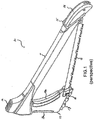
- FIG. 1 illustrates a perspective view of the multi-purpose tool 10, according to one embodiment.
- the multi-purpose tool 10 includes a handle 12 connected to a frame 11.
- the handle 12 can include cushions 19a and 19b on either side thereof.
- a bale 14 and stake puller 15 may be attached to one end of the frame 11.
- a removable saw blade 13 is connected to the handle and frame 11, as discussed in more detail below.
- a mallet 16 may be provided on one end of the frame 11.
- the multi-purpose tool 10 may also include a hinge 17 and pin 18 that will be discussed in more detail below.
- the frame 11 may include a cavity or channel that provides space to store one or more saw blades, such as removable saw blade 13, when they are not in use.
- Fig. 2 illustrates a side view of the multi-purpose tool 10, including handle 12, mallet 16, frame 11, bale 14, and stake puller 15, according to one embodiment.
- the multi-purpose tool 10 includes a compensating clip 20 configured to attach the removable saw blade 13 to the frame 11 of the multi-purpose tool 10.
- the components and function of the compensating clip 20 will be discussed in more detail below.
- handle 12 may include a hinge 17 and pin 18.
- the pin 18 is configured to attach the removable saw blade 13 to the handle 12 of the multi-purpose tool 10.
- the pin 18 may be any means or mechanism for securing saw blade 13 onto axe blade 50 by being fastened into lower portion 12b.
- Fig. 3 illustrates an example of the multi-purpose tool 10 with the handle 12 and bale 14 in open positions.
- the handle 12 may include an upper portion 12a and a lower portion 12b.
- the multi-purpose tool 10 may also include an axe blade 50 situated between the upper portion 12a and lower portion 12b.
- the handle 12 may act as a cover or sheath for the axe blade 50.
- the upper portion 12a and lower portion 12b of the handle may be completely removed to expose the axe blade 50, and the frame 11 may be used as handle for gripping and swinging the axe.
- the upper portion 12a and lower portion 12b of handle 12 may be attached to each other via hinge 17 such that the upper portion 12a may swing open away from lower portion 12b and away from axe blade 50, as shown in Fig. 3 .
- the removable saw blade 13 includes one or more holes 24 on one thereof and one or more holes 23 on another end thereof.
- one end of the removable saw blade 13 can be placed onto axe blade 50 and secured by the pin 18 inserted in the upper portion 12a and the upper portion 12a may be rotated via hinge 17 into a closed position, as illustrated above in Figs. 1 and 2 .
- the removable saw blade 13 may be secured within the handle 12 by the pin 18 that can be passed through a hole 25 in the upper portion 12a, through the at least one hole 24 in the removable saw blade 13, through axe blade 50, and fastened into lower portion 12b, thereby securing the removable saw blade 13 to the handle 12.
- the pin 18 may be any means or mechanism for securing saw blade 13 onto axe blade 50 by being fastened into lower portion 12b.
- the bale 14 may be swingably attached to the frame 11 such that the bale 14 may rotate in the longitudinal direction of the frame to an open position shown in Fig. 3 .
- the stake puller 15 may be attached to the bale 14 and may rotate with bale 14 while in its closed position. The closed position of the bale 14 is shown in Figs. 1 and 2 discussed above.
- the multi-purpose tool 10 includes a compensating clip 20 attached to the bale 14, which is located on an end of the frame 11 opposite from the handle 12.
- the compensating clip includes a center section 29 including plate that is integral with a clip hook 28.
- the center section 29 also includes an opening or window 26 in which a compensator spring 27 is located.
- the compensating clip may also include a retention structure 30 covering the center section 29.
- the retention structure 30 is a bracket.
- the bracket may be a U-shaped bracket.
- the clip hook 28 may engage onto the at least one hole 23 on one end of the removable saw blade 13 in order to attach the removable saw blade to the frame 11 and bale 14.
- the bale 14 when the removable saw blade 13 is to be attached to the bale 14, the bale 14 is moved to the open position illustrated in Fig. 3 in order to release the compensating clip from the storage position inside the bale 14.
- One of the holes 23 on one end of the removable saw blade 13 may then be placed over the clip hook 28 of the compensating clip 20.
- the bale 14 may then be moved to the locked position integral with the frame 11, as illustrated in Figs. 1 and 2 , such that the compensating clip 20 via the compensator spring 27 provides the tension to lock the saw blade 13 into place for proper use.
- the compensating clip 20 including the compensator spring 27 is configured as a tension mechanism to provide the appropriate tension onto the removable saw blade 13.
- Fig. 3 depicts the compensator spring 27 as a coiled compression spring, embodiments are not limited to such a spring.
- Spring 27 may be made up of any structure(s), component(s), or materials that can provide resiliency from compression and elongation.
- spring 27 may be a thin piece of metal capable of flexing, or an elastomeric element that compresses and rebounds
- the removable saw blade 13 is attached onto the handle 12 first, and then is attached to the bale 14 by means of the compensating clip 20.
- the bale 14 is then closed to apply the tension onto the removable saw blade 13, and the compensator spring 27 compensates for any tolerances.
- the compensator spring 27 is able to overcome manufacturing tolerances in the saw blades resulting from production lot variations, different blade manufacturers, and tolerances in the manufacture of the multi-purpose tool 10.
- the frame 11 can be made rigid since the multi-purpose tool 10 does not rely on the frame 11 to flex in order to provide appropriate tension for the saw blade 13. It should be noted that, typically, many saws do rely on their frames to flex in order to provide the tension and may include screw adjustment mechanisms or other adjustment means that require manual interaction.
- Fig. 4 illustrates a partial exploded view of the multi-purpose tool 10 including the components of the compensating clip 20, frame 11, bale 14, stake puller 15, and removable saw blade 13 with the at least one hole 23, prior to assembly.
- the compensating clip 20 includes the center section 29 which includes the clip hook 28, spring 27 within opening 26, and a hole 33.
- the retention structure 30 includes an opening 34 and hole 32.
- the opening 34 coincides with the opening 26 of the center section 29, and the hole 32 coincides with the hole 33 of the center section 29, when the retention structure 30 is placed over the center section 29.
- the stake puller 15 may include two ends 42, 43 that may respectively be inserted into each side of hole 41 of the bale 14 and inserted into each side of hole 37 in frame 11. As a result, the ends 42, 43 of the stake puller 15 may act as an axis of rotation for the bale 14.
- the multi-purpose tool 10 may also include a cylindrical shaped pin 31 configured to attach the compensating clip 20 to the multi-purpose tool 10.
- the pin 31 is configured to be inserted through the hole 40 of the bale 14, the hole 32 of the retention structure 30, and the hole 33 of the center section 29. The pin 31 may then be locked into place by a washer 35.
- Figs. 5 and 6 illustrate the elements of the compensating clip 20 in their assembled form, according to one embodiment.
- the compensating clip 20 may include additional features and components which may enhance the assembly and integrity of the assembly.
- embodiments of the invention provide a multi-purpose tool 10 which is used as a saw and that overcomes manufacturing tolerances in the saw blades resulting from production lot variations, different blade manufacturers, and tolerances in the manufacture of the multi-purpose tool 10. Therefore, in some embodiments, compensating clip 20 may be considered a tolerance compensator mechanism. Additionally, in some embodiments, the multi-purpose tool can be used as an axe, mallet, and/or stake puller.
- the compensating clip 20 of the claimed tool is a tolerance compensator mechanism that could be used in other tools and products not according to the invention that require a "self-adjusting" feature or mechanism to overcome tolerances and other variations for proper assembly and function.
Landscapes
- Life Sciences & Earth Sciences (AREA)
- Engineering & Computer Science (AREA)
- Mechanical Engineering (AREA)
- Wood Science & Technology (AREA)
- Forests & Forestry (AREA)
- Sawing (AREA)
- Processing Of Stones Or Stones Resemblance Materials (AREA)
- Shovels (AREA)
- Portable Power Tools In General (AREA)
- Road Repair (AREA)
Description
- The invention relates to a too according to the preamble of claim 1 and to method of tensioning a blade on a saw according to the preamble of
claim 11. - Outdoor tools can be used for a variety of tasks, such as cutting, sawing, chopping, woodworking, building, etc. One common outdoor tool is a bow saw used for sawing a workpiece such as a tree branch. Bow saws generally have a metal frame in the shape of a bow and a coarse wide blade attached to a handle. Another common tool is an axe, which is generally used to shape, split and cut wood or to harvest timber, for example. An axe may have many forms and uses, but generally includes an axe head with a handle, or helve. Another common tool is a mallet, which may be considered as a kind of hammer. Mallet heads are relatively large and are usually made of rubber, but can sometimes be made of wood, for example. A stake puller, as suggested by its name, is an outdoor tool that can be used to pull wooden or metal stakes from the ground.
-
US 2004/0074099 discloses the preambles ofclaims 1 and 11, in particular a hand-saw which includes two holding sections, a front and a rear holding section, a sawing blade, a front-mounted ratchet teeth fine tuning block having one end with four teeth ratchet, the other end there of being a semicircular and having a protruded cylindrical bar for the insertion of the sawing blade, a ratchet teeth adjusting sleeve being cylindrical shape having one end with inner edge being ratchet teeth shape, and the other end thereof being a larger internal radius, a rear-mounted ratchet wheel fine tuning block having an external edge with four ratchet teeth for engagement with the ratchet-teeth adjusting sleeve for the insertion of the other end of the sawing blade, a hexagonal pull-push engaging connector module having a circular shape center and a cavity adaptable to a hexagonal shape screw nut, and a loosening button located at the root section of the rear holding section used to adjust the fine tune angle of the hexagonal screw nut. - The invention is defined by the claims.
- The invention will now be further described by way of example with reference to the accompanying drawings, in which:
-
Fig. 1 illustrates a perspective view of the multi-purpose tool, according to one embodiment; -
Fig. 2 illustrates a side view of the multi-purpose tool, according to one embodiment; -
Fig. 3 illustrates another side view of the multi-purpose tool with portions in an open position, according to an embodiment; -
Fig. 4 illustrates a partial exploded view of the multi-purpose tool, according to an embodiment; -
Fig. 5 illustrates an example of the compensating clip assembly of the multi-purpose tool, according to an embodiment; and -
Fig. 6 illustrates another example of the compensating clip assembly of the multi-purpose tool, according to another embodiment. - One embodiment is directed to a multi-purpose tool that can include a saw, axe, mallet, and/or stake puller.
Fig. 1 illustrates a perspective view of themulti-purpose tool 10, according to one embodiment. As illustrated inFig. 1 , in this example, themulti-purpose tool 10 includes ahandle 12 connected to aframe 11. Thehandle 12 can include cushions 19a and 19b on either side thereof. In certain embodiments, abale 14 andstake puller 15 may be attached to one end of theframe 11. Additionally, when themulti-purpose tool 10 is used as a saw, aremovable saw blade 13 is connected to the handle andframe 11, as discussed in more detail below. Amallet 16 may be provided on one end of theframe 11. Themulti-purpose tool 10 may also include ahinge 17 andpin 18 that will be discussed in more detail below. - In one embodiment, the
frame 11 may include a cavity or channel that provides space to store one or more saw blades, such asremovable saw blade 13, when they are not in use. -
Fig. 2 illustrates a side view of themulti-purpose tool 10, includinghandle 12,mallet 16,frame 11,bale 14, andstake puller 15, according to one embodiment. As illustrated inFig. 2 , themulti-purpose tool 10 includes a compensatingclip 20 configured to attach theremovable saw blade 13 to theframe 11 of themulti-purpose tool 10. The components and function of the compensatingclip 20 will be discussed in more detail below. As also illustrated inFig. 2 ,handle 12 may include ahinge 17 andpin 18. In some embodiments, thepin 18 is configured to attach theremovable saw blade 13 to thehandle 12 of themulti-purpose tool 10. According to an embodiment, thepin 18 may be any means or mechanism for securingsaw blade 13 onto axe blade 50 by being fastened into lower portion 12b. -
Fig. 3 illustrates an example of themulti-purpose tool 10 with thehandle 12 and bale 14 in open positions. As illustrated inFig. 3 , thehandle 12 may include an upper portion 12a and a lower portion 12b. Themulti-purpose tool 10 may also include an axe blade 50 situated between the upper portion 12a and lower portion 12b. As a result, thehandle 12 may act as a cover or sheath for the axe blade 50. In an embodiment, when the multi-purpose tool is used as an axe, the upper portion 12a and lower portion 12b of the handle may be completely removed to expose the axe blade 50, and theframe 11 may be used as handle for gripping and swinging the axe. The upper portion 12a and lower portion 12b ofhandle 12 may be attached to each other viahinge 17 such that the upper portion 12a may swing open away from lower portion 12b and away from axe blade 50, as shown inFig. 3 . - Further, as illustrated in
Fig. 3 , theremovable saw blade 13 includes one or more holes 24 on one thereof and one ormore holes 23 on another end thereof. When in the open position, one end of theremovable saw blade 13 can be placed onto axe blade 50 and secured by thepin 18 inserted in the upper portion 12a and the upper portion 12a may be rotated viahinge 17 into a closed position, as illustrated above inFigs. 1 and2 . More specifically, in an embodiment, theremovable saw blade 13 may be secured within thehandle 12 by thepin 18 that can be passed through a hole 25 in the upper portion 12a, through the at least one hole 24 in theremovable saw blade 13, through axe blade 50, and fastened into lower portion 12b, thereby securing theremovable saw blade 13 to thehandle 12. - According to an embodiment, the
pin 18 may be any means or mechanism for securingsaw blade 13 onto axe blade 50 by being fastened into lower portion 12b. - In addition, the
bale 14 may be swingably attached to theframe 11 such that thebale 14 may rotate in the longitudinal direction of the frame to an open position shown inFig. 3 . In an embodiment, thestake puller 15 may be attached to thebale 14 and may rotate withbale 14 while in its closed position. The closed position of thebale 14 is shown inFigs. 1 and2 discussed above. - As also illustrated in
Fig. 3 , themulti-purpose tool 10 includes a compensatingclip 20 attached to thebale 14, which is located on an end of theframe 11 opposite from thehandle 12. The compensating clip includes acenter section 29 including plate that is integral with aclip hook 28. Thecenter section 29 also includes an opening orwindow 26 in which a compensator spring 27 is located. The compensating clip may also include aretention structure 30 covering thecenter section 29. In one embodiment, theretention structure 30 is a bracket. In some embodiments, the bracket may be a U-shaped bracket. - In one embodiment, the
clip hook 28 may engage onto the at least onehole 23 on one end of theremovable saw blade 13 in order to attach the removable saw blade to theframe 11 and bale 14. For example, according to one embodiment, when theremovable saw blade 13 is to be attached to thebale 14, thebale 14 is moved to the open position illustrated inFig. 3 in order to release the compensating clip from the storage position inside thebale 14. One of theholes 23 on one end of theremovable saw blade 13 may then be placed over theclip hook 28 of the compensatingclip 20. Thebale 14 may then be moved to the locked position integral with theframe 11, as illustrated inFigs. 1 and2 , such that the compensatingclip 20 via the compensator spring 27 provides the tension to lock thesaw blade 13 into place for proper use. As a result, in one embodiment, the compensatingclip 20 including the compensator spring 27 is configured as a tension mechanism to provide the appropriate tension onto theremovable saw blade 13. - It should be noted that, while
Fig. 3 depicts the compensator spring 27 as a coiled compression spring, embodiments are not limited to such a spring. Spring 27 may be made up of any structure(s), component(s), or materials that can provide resiliency from compression and elongation. For example, spring 27 may be a thin piece of metal capable of flexing, or an elastomeric element that compresses and rebounds - In one embodiment, the
removable saw blade 13 is attached onto thehandle 12 first, and then is attached to thebale 14 by means of the compensatingclip 20. Thebale 14 is then closed to apply the tension onto theremovable saw blade 13, and the compensator spring 27 compensates for any tolerances. - According to certain embodiments, the compensator spring 27 is able to overcome manufacturing tolerances in the saw blades resulting from production lot variations, different blade manufacturers, and tolerances in the manufacture of the
multi-purpose tool 10. As a result, in some embodiments, theframe 11 can be made rigid since themulti-purpose tool 10 does not rely on theframe 11 to flex in order to provide appropriate tension for thesaw blade 13. It should be noted that, typically, many saws do rely on their frames to flex in order to provide the tension and may include screw adjustment mechanisms or other adjustment means that require manual interaction. -
Fig. 4 illustrates a partial exploded view of themulti-purpose tool 10 including the components of the compensatingclip 20,frame 11,bale 14,stake puller 15, andremovable saw blade 13 with the at least onehole 23, prior to assembly. As illustrated inFig. 4 , the compensatingclip 20 includes thecenter section 29 which includes theclip hook 28, spring 27 withinopening 26, and a hole 33. Theretention structure 30 includes an opening 34 andhole 32. The opening 34 coincides with theopening 26 of thecenter section 29, and thehole 32 coincides with the hole 33 of thecenter section 29, when theretention structure 30 is placed over thecenter section 29. Thestake puller 15 may include two ends 42, 43 that may respectively be inserted into each side ofhole 41 of thebale 14 and inserted into each side ofhole 37 inframe 11. As a result, the ends 42, 43 of thestake puller 15 may act as an axis of rotation for thebale 14. - As further illustrated in
Fig. 4 , themulti-purpose tool 10 may also include a cylindrical shapedpin 31 configured to attach the compensatingclip 20 to themulti-purpose tool 10. In one embodiment, thepin 31 is configured to be inserted through the hole 40 of thebale 14, thehole 32 of theretention structure 30, and the hole 33 of thecenter section 29. Thepin 31 may then be locked into place by awasher 35.Figs. 5 and6 illustrate the elements of the compensatingclip 20 in their assembled form, according to one embodiment. - In some embodiments, the compensating
clip 20 may include additional features and components which may enhance the assembly and integrity of the assembly. - Thus, embodiments of the invention provide a
multi-purpose tool 10 which is used as a saw and that overcomes manufacturing tolerances in the saw blades resulting from production lot variations, different blade manufacturers, and tolerances in the manufacture of themulti-purpose tool 10. Therefore, in some embodiments, compensatingclip 20 may be considered a tolerance compensator mechanism. Additionally, in some embodiments, the multi-purpose tool can be used as an axe, mallet, and/or stake puller. - It should be noted that the compensating
clip 20 of the claimed tool is a tolerance compensator mechanism that could be used in other tools and products not according to the invention that require a "self-adjusting" feature or mechanism to overcome tolerances and other variations for proper assembly and function.
Claims (11)
- A tool, comprising a handle (12) for gripping a multi-purpose tool, a removable saw blade (13) comprising at least one hole (24) on one end thereof and at least one hole (23) on another end thereof, a frame (11) for supporting the blade (13), compensating means (20) for attaching the blade (13) to the frame (11) and for providing tension for the blade (13) means, wherein the compensating means (20) includes an attachment means for attaching the blade (13) and a compensator spring (27), wherein the attachment means is configured to attach into the at least one hole (23) of the blade (13), characterized in that the compensating means comprises a plate including the attachment means; in that the plate further comprises an opening (26) and the compensator spring (27) is provided in the opening (26) of the plate; in that the compensating means comprises a compensating clip (20) configured to attach the blade (13) to the frame (11), and in that the attachment means comprises a clip hook (28).
- The tool according to claim 1, wherein the handle comprises an upper section (12a) and a lower section (12b), and the upper section and lower section are swingably attached to each other by a hinge (17).
- The tool according to claim 2, wherein the upper section (12a) of the handle comprises a hole, and a pin (18) is configured to be inserted through the hole of the handle and the at least one hole (24) on the one end of the blade (13) to attach the removable saw blade (13) to the handle (12).
- The tool according to any preceding claim, wherein the compensating clip (20) further comprises a retention structure (30) configured to fit over the plate.
- The tool according to any preceding claim, further comprising a bale (14) configured to rotate in the longitudinal direction of the frame to an open position to relieve tension in order to allow the clip hook (28) to attach into the at least one hole (23) of the removable saw blade.
- The tool according to any preceding claim, further comprising a pin (31) and a locking washer (35) configured to attach the compensating clip (20) to the bale (14).
- The tool according to any preceding claim, further comprising a stake puller (15).
- The tool according to any preceding claim, further comprising a mallet (16).
- The tool according to any preceding claim, wherein the frame comprises a channel that provides space to store at least one saw blade.
- The tool according to any preceding claim, further comprising an axe blade (50).
- A method of tensioning a blade on a saw, the method comprising: providing a frame (11); providing a removable saw blade (13) comprising at least one hole (24) on one end thereof and at least one hole (23) on another end thereof; and providing tension for the removable saw blade (13), characterized in that the tension is provided by a compensating clip (20) configured to attach the removable saw blade (13) to the frame (11), the compensating clip (20) comprising a plate including a clip hook (28), wherein the plate further comprises an opening (26) and a compensator spring (27) is provided in the opening (26) of the plate, and wherein the clip hook (28) is configured to attach into the at least one hole (23) of the removable saw blade (11).
Priority Applications (1)
| Application Number | Priority Date | Filing Date | Title |
|---|---|---|---|
| DE13165177.0T DE13165177T1 (en) | 2012-04-27 | 2013-04-24 | Multipurpose tool and clamping mechanism |
Applications Claiming Priority (2)
| Application Number | Priority Date | Filing Date | Title |
|---|---|---|---|
| US201261639298P | 2012-04-27 | 2012-04-27 | |
| US13/476,148 US9333572B2 (en) | 2012-04-27 | 2012-05-21 | Multi-purpose tool and tension mechanism |
Publications (3)
| Publication Number | Publication Date |
|---|---|
| EP2656989A1 EP2656989A1 (en) | 2013-10-30 |
| EP2656989A8 EP2656989A8 (en) | 2013-12-04 |
| EP2656989B1 true EP2656989B1 (en) | 2016-07-20 |
Family
ID=48193115
Family Applications (1)
| Application Number | Title | Priority Date | Filing Date |
|---|---|---|---|
| EP13165177.0A Not-in-force EP2656989B1 (en) | 2012-04-27 | 2013-04-24 | Multi-purpose tool and tension mechanism |
Country Status (8)
| Country | Link |
|---|---|
| US (1) | US9333572B2 (en) |
| EP (1) | EP2656989B1 (en) |
| CN (1) | CN103372853B (en) |
| AU (1) | AU2013205421B2 (en) |
| BR (1) | BR102013010402A2 (en) |
| CA (1) | CA2813876C (en) |
| DE (1) | DE13165177T1 (en) |
| TW (1) | TWI507259B (en) |
Families Citing this family (12)
| Publication number | Priority date | Publication date | Assignee | Title |
|---|---|---|---|---|
| US8881411B2 (en) | 2008-11-28 | 2014-11-11 | Irwin Industrial Tool Company | Hacksaw with blade tensioning mechanism |
| USD724925S1 (en) | 2012-05-21 | 2015-03-24 | Zippo Manufacturing Company | Multi-purpose tool |
| US9463516B2 (en) * | 2013-03-14 | 2016-10-11 | Irwin Industrial Tool Company | Retained aligning rotating hack saw blade tensioning mechanism and related method |
| CN105081461A (en) * | 2014-05-12 | 2015-11-25 | 苏州天脉导热科技有限公司 | Tightness mechanism of sawing machine |
| USD755034S1 (en) | 2015-04-02 | 2016-05-03 | Milwaukee Electric Tool Corporation | Saw |
| US11846187B2 (en) * | 2017-08-30 | 2023-12-19 | Itr America, Llc | Mining pin retention system |
| CN108142136A (en) * | 2017-12-26 | 2018-06-12 | 姜敏敏 | A kind of convenient handsaw in the gardens of Multifunction |
| US11559878B2 (en) * | 2018-07-20 | 2023-01-24 | Miw Associates Llc | Multi-use tool |
| CN109014746A (en) * | 2018-10-23 | 2018-12-18 | 东风(武汉)汽车零部件有限公司 | A kind of tool structure suitable for the welding of automobile top cover back veneer top nut plate |
| US11148274B2 (en) * | 2019-05-15 | 2021-10-19 | Usa Products Group | Multi-task tool assembly with detachable load tension body |
| CN111590521A (en) * | 2020-05-25 | 2020-08-28 | 贵州电网有限责任公司 | Saw bow hammer |
| US20250091238A1 (en) * | 2023-09-19 | 2025-03-20 | Joseph Magiera | cutting tool |
Family Cites Families (37)
| Publication number | Priority date | Publication date | Assignee | Title |
|---|---|---|---|---|
| US1882328A (en) * | 1930-09-09 | 1932-10-11 | Kinkel Heinrich | Blade for hack saws |
| US2102782A (en) * | 1934-02-02 | 1937-12-21 | Armstrong Blum Mfg Co | Hacksaw |
| US2101362A (en) * | 1936-03-30 | 1937-12-07 | Armstrong Blum Mfg Co | Hacksaw |
| US2213841A (en) * | 1938-07-14 | 1940-09-03 | Hubeck Charles | Hacksaw blade mounting |
| US2253440A (en) * | 1938-11-28 | 1941-08-19 | Paul E Martin | Hacksaw |
| US2519904A (en) | 1946-11-18 | 1950-08-22 | Allan A Hendricksen | Saw blade tension mechanism for frame saws |
| US2576869A (en) | 1949-12-03 | 1951-11-27 | Edgar C Woltemath | Combination hand ax and saw |
| US3589418A (en) * | 1969-05-15 | 1971-06-29 | Arthur E Clark | Handsaw with blade tension setter and absorber |
| US4367779A (en) * | 1981-03-23 | 1983-01-11 | Parker Manufacturing Company | Hacksaw with improved blade tensioning mechanism |
| US4466471A (en) * | 1983-07-07 | 1984-08-21 | Parker Manufacturing Company | Hacksaw with improved blade-tensioning mechanism |
| US5025905A (en) * | 1989-09-06 | 1991-06-25 | Contact Technologies Inc. | Hand control |
| US5271158A (en) | 1993-02-11 | 1993-12-21 | Chen Chun Chiung | Saw blade adjusting device |
| US5388333A (en) * | 1994-04-28 | 1995-02-14 | Chen; Chun-Chiung | Saw blade adjusting mechanism |
| US5542139A (en) * | 1994-12-20 | 1996-08-06 | Boivin; Gregory E. | Multi-purpose tool for cutting, prying and punching in the event of an emergency situation |
| US5706583A (en) * | 1996-06-25 | 1998-01-13 | Gengenbach; Robert J. | Twin utility hacksaw blade |
| US5826344A (en) * | 1996-11-13 | 1998-10-27 | R.E. Phelon Company, Inc. | Hacksaw having cam-actuated blade tensioning mechanism |
| US5722173A (en) * | 1996-12-16 | 1998-03-03 | Huang; Yin Han | Saw blade adjusting mechanism |
| GB2330555A (en) * | 1997-10-24 | 1999-04-28 | Yin Han Huang | Blade tensioning in hacksaws |
| US6266887B1 (en) * | 1999-08-10 | 2001-07-31 | The Stanley Works | Hacksaw and method for making the same |
| US6457244B1 (en) * | 2001-06-28 | 2002-10-01 | Yin-Hae Huang | Structure of a hacksaw |
| US20030056377A1 (en) * | 2001-09-21 | 2003-03-27 | Huang Yin Han | Hacksaw having a lock device for a quick release lever |
| US6662681B2 (en) * | 2002-01-14 | 2003-12-16 | Kent Demolition, Inc. | Connector assembly for mounting an implement to a prime mover |
| DE20204158U1 (en) | 2002-03-14 | 2002-05-29 | Hazet-Werk Hermann Zerver GmbH & Co. KG, 42857 Remscheid | hacksaw |
| US6729030B2 (en) * | 2002-06-13 | 2004-05-04 | Yin Han Huang | Hacksaw having easily operated blade tension device |
| US20040020062A1 (en) * | 2002-07-30 | 2004-02-05 | Seatek Co., Inc. | Foldable handsaw |
| US6742268B2 (en) * | 2002-10-21 | 2004-06-01 | Chun-Chiung Chen | Structure of a hand-saw |
| US6772522B1 (en) * | 2003-08-07 | 2004-08-10 | Yin-Hae Huang | Quick disassembly hacksaw |
| US6925720B2 (en) * | 2003-08-26 | 2005-08-09 | The Stanley Works | Hacksaw with blade tension adjustment mechanism |
| US6916106B2 (en) * | 2003-10-10 | 2005-07-12 | Acumen, Inc. | Bicycle repair tool assembly |
| US7174644B2 (en) * | 2004-05-13 | 2007-02-13 | Cooper Brands, Inc. | Handsaw with blade storage and auxiliary blade |
| US7254893B1 (en) * | 2006-03-20 | 2007-08-14 | Yin-Hai Huang | Blade quick removal device for a handsaw |
| CN201002144Y (en) * | 2006-12-28 | 2008-01-09 | 邬明君 | Hand saw embedding combination tool |
| DE202007015510U1 (en) | 2007-11-07 | 2008-04-03 | Chen, Teng-Lung, Wu-Jih | hacksaw |
| US20090113729A1 (en) * | 2007-11-07 | 2009-05-07 | Teng-Lung Chen | Hacksaw |
| AU2010210498B2 (en) * | 2009-02-05 | 2014-08-07 | Milwaukee Electric Tool Corporation | Hand saw |
| CN201500822U (en) * | 2009-09-04 | 2010-06-09 | 上海昆杰五金工具有限公司 | Safe Storage of Saw Blades for Hand Saws |
| US8033199B1 (en) * | 2010-06-09 | 2011-10-11 | Noble Martin G | Nail set hammer |
-
2012
- 2012-05-21 US US13/476,148 patent/US9333572B2/en not_active Expired - Fee Related
-
2013
- 2013-04-22 CA CA2813876A patent/CA2813876C/en active Active
- 2013-04-24 AU AU2013205421A patent/AU2013205421B2/en not_active Ceased
- 2013-04-24 EP EP13165177.0A patent/EP2656989B1/en not_active Not-in-force
- 2013-04-24 DE DE13165177.0T patent/DE13165177T1/en active Pending
- 2013-04-25 CN CN201310240187.8A patent/CN103372853B/en active Active
- 2013-04-26 TW TW102114945A patent/TWI507259B/en not_active IP Right Cessation
- 2013-04-29 BR BRBR102013010402-7A patent/BR102013010402A2/en not_active IP Right Cessation
Also Published As
| Publication number | Publication date |
|---|---|
| TW201402254A (en) | 2014-01-16 |
| US20130283540A1 (en) | 2013-10-31 |
| EP2656989A8 (en) | 2013-12-04 |
| HK1186436A1 (en) | 2014-03-14 |
| EP2656989A1 (en) | 2013-10-30 |
| US9333572B2 (en) | 2016-05-10 |
| TWI507259B (en) | 2015-11-11 |
| CA2813876A1 (en) | 2013-10-27 |
| CN103372853A (en) | 2013-10-30 |
| BR102013010402A2 (en) | 2015-06-23 |
| CA2813876C (en) | 2015-10-13 |
| DE13165177T1 (en) | 2014-08-21 |
| CN103372853B (en) | 2015-11-25 |
| AU2013205421A1 (en) | 2013-11-14 |
| AU2013205421B2 (en) | 2016-12-22 |
Similar Documents
| Publication | Publication Date | Title |
|---|---|---|
| CA2813876C (en) | Multi-purpose tool and tension mechanism | |
| US8763260B2 (en) | Modular saw | |
| AU2016239724B2 (en) | Device for holding a pivoting cutting blade | |
| US7895757B1 (en) | Gardening shears having energy-saving function | |
| US20110061249A1 (en) | Cutting Implement with Interchangeable/Replaceable Blades | |
| US6772522B1 (en) | Quick disassembly hacksaw | |
| US6694623B1 (en) | Lever chain adjuster for a chain saw | |
| US9101095B2 (en) | Foldable-storable pole saw | |
| US9180535B2 (en) | Multi tool saw | |
| JP3513020B2 (en) | Cutting tool | |
| US20150122090A1 (en) | On-board hand tool accessory | |
| CA2471138C (en) | Hacksaw with blade tension adjustment mechanism | |
| EP2492070A1 (en) | Chainsaw, particularly for trimming trees and bushes | |
| EP2110016A1 (en) | Adjustment device for manual cutting tools | |
| US11559878B2 (en) | Multi-use tool | |
| HK1186436B (en) | Multi-purpose tool and tension mechanism | |
| US20150020392A1 (en) | Hand saw | |
| CN113618662B (en) | Clamp for detaching blade of mower | |
| US5577325A (en) | Wood cutting blade attachment device | |
| DE102011006931A1 (en) | Handle for cable wrapping | |
| CN107617784B (en) | A kind of handsaw being conveniently replaceable saw blade | |
| EP4406711A1 (en) | Spring assisted adjustable log rest and clamp assembly | |
| EP1792534B1 (en) | Coupling, and angular adjustment assembly, particularly for agricultural tools | |
| AU764004B1 (en) | Coupling device of free-cutting saw | |
| KR200224561Y1 (en) | Saw of wood |
Legal Events
| Date | Code | Title | Description |
|---|---|---|---|
| PUAI | Public reference made under article 153(3) epc to a published international application that has entered the european phase |
Free format text: ORIGINAL CODE: 0009012 |
|
| AK | Designated contracting states |
Kind code of ref document: A1 Designated state(s): AL AT BE BG CH CY CZ DE DK EE ES FI FR GB GR HR HU IE IS IT LI LT LU LV MC MK MT NL NO PL PT RO RS SE SI SK SM TR |
|
| AX | Request for extension of the european patent |
Extension state: BA ME |
|
| 17P | Request for examination filed |
Effective date: 20140428 |
|
| RBV | Designated contracting states (corrected) |
Designated state(s): AL AT BE BG CH CY CZ DE DK EE ES FI FR GB GR HR HU IE IS IT LI LT LU LV MC MK MT NL NO PL PT RO RS SE SI SK SM TR |
|
| REG | Reference to a national code |
Ref country code: SE Ref legal event code: TRCL |
|
| REG | Reference to a national code |
Ref country code: DE Ref legal event code: R210 Ref document number: 602013009502 Country of ref document: DE Effective date: 20140821 Ref country code: DE Ref legal event code: R210 Effective date: 20140821 |
|
| REG | Reference to a national code |
Ref country code: FR Ref legal event code: EL |
|
| GRAP | Despatch of communication of intention to grant a patent |
Free format text: ORIGINAL CODE: EPIDOSNIGR1 |
|
| INTG | Intention to grant announced |
Effective date: 20160223 |
|
| GRAR | Information related to intention to grant a patent recorded |
Free format text: ORIGINAL CODE: EPIDOSNIGR71 |
|
| GRAS | Grant fee paid |
Free format text: ORIGINAL CODE: EPIDOSNIGR3 |
|
| GRAA | (expected) grant |
Free format text: ORIGINAL CODE: 0009210 |
|
| INTG | Intention to grant announced |
Effective date: 20160607 |
|
| AK | Designated contracting states |
Kind code of ref document: B1 Designated state(s): AL AT BE BG CH CY CZ DE DK EE ES FI FR GB GR HR HU IE IS IT LI LT LU LV MC MK MT NL NO PL PT RO RS SE SI SK SM TR |
|
| REG | Reference to a national code |
Ref country code: GB Ref legal event code: FG4D |
|
| REG | Reference to a national code |
Ref country code: CH Ref legal event code: EP |
|
| REG | Reference to a national code |
Ref country code: IE Ref legal event code: FG4D |
|
| REG | Reference to a national code |
Ref country code: AT Ref legal event code: REF Ref document number: 813660 Country of ref document: AT Kind code of ref document: T Effective date: 20160815 |
|
| REG | Reference to a national code |
Ref country code: DE Ref legal event code: R096 Ref document number: 602013009502 Country of ref document: DE |
|
| REG | Reference to a national code |
Ref country code: NL Ref legal event code: FP |
|
| REG | Reference to a national code |
Ref country code: LT Ref legal event code: MG4D |
|
| REG | Reference to a national code |
Ref country code: AT Ref legal event code: MK05 Ref document number: 813660 Country of ref document: AT Kind code of ref document: T Effective date: 20160720 |
|
| PG25 | Lapsed in a contracting state [announced via postgrant information from national office to epo] |
Ref country code: HR Free format text: LAPSE BECAUSE OF FAILURE TO SUBMIT A TRANSLATION OF THE DESCRIPTION OR TO PAY THE FEE WITHIN THE PRESCRIBED TIME-LIMIT Effective date: 20160720 Ref country code: RS Free format text: LAPSE BECAUSE OF FAILURE TO SUBMIT A TRANSLATION OF THE DESCRIPTION OR TO PAY THE FEE WITHIN THE PRESCRIBED TIME-LIMIT Effective date: 20160720 Ref country code: IS Free format text: LAPSE BECAUSE OF FAILURE TO SUBMIT A TRANSLATION OF THE DESCRIPTION OR TO PAY THE FEE WITHIN THE PRESCRIBED TIME-LIMIT Effective date: 20161120 Ref country code: FI Free format text: LAPSE BECAUSE OF FAILURE TO SUBMIT A TRANSLATION OF THE DESCRIPTION OR TO PAY THE FEE WITHIN THE PRESCRIBED TIME-LIMIT Effective date: 20160720 Ref country code: LT Free format text: LAPSE BECAUSE OF FAILURE TO SUBMIT A TRANSLATION OF THE DESCRIPTION OR TO PAY THE FEE WITHIN THE PRESCRIBED TIME-LIMIT Effective date: 20160720 Ref country code: NO Free format text: LAPSE BECAUSE OF FAILURE TO SUBMIT A TRANSLATION OF THE DESCRIPTION OR TO PAY THE FEE WITHIN THE PRESCRIBED TIME-LIMIT Effective date: 20161020 Ref country code: IT Free format text: LAPSE BECAUSE OF FAILURE TO SUBMIT A TRANSLATION OF THE DESCRIPTION OR TO PAY THE FEE WITHIN THE PRESCRIBED TIME-LIMIT Effective date: 20160720 |
|
| PG25 | Lapsed in a contracting state [announced via postgrant information from national office to epo] |
Ref country code: ES Free format text: LAPSE BECAUSE OF FAILURE TO SUBMIT A TRANSLATION OF THE DESCRIPTION OR TO PAY THE FEE WITHIN THE PRESCRIBED TIME-LIMIT Effective date: 20160720 Ref country code: PT Free format text: LAPSE BECAUSE OF FAILURE TO SUBMIT A TRANSLATION OF THE DESCRIPTION OR TO PAY THE FEE WITHIN THE PRESCRIBED TIME-LIMIT Effective date: 20161121 Ref country code: PL Free format text: LAPSE BECAUSE OF FAILURE TO SUBMIT A TRANSLATION OF THE DESCRIPTION OR TO PAY THE FEE WITHIN THE PRESCRIBED TIME-LIMIT Effective date: 20160720 Ref country code: BE Free format text: LAPSE BECAUSE OF FAILURE TO SUBMIT A TRANSLATION OF THE DESCRIPTION OR TO PAY THE FEE WITHIN THE PRESCRIBED TIME-LIMIT Effective date: 20160720 Ref country code: AT Free format text: LAPSE BECAUSE OF FAILURE TO SUBMIT A TRANSLATION OF THE DESCRIPTION OR TO PAY THE FEE WITHIN THE PRESCRIBED TIME-LIMIT Effective date: 20160720 Ref country code: GR Free format text: LAPSE BECAUSE OF FAILURE TO SUBMIT A TRANSLATION OF THE DESCRIPTION OR TO PAY THE FEE WITHIN THE PRESCRIBED TIME-LIMIT Effective date: 20161021 Ref country code: SE Free format text: LAPSE BECAUSE OF FAILURE TO SUBMIT A TRANSLATION OF THE DESCRIPTION OR TO PAY THE FEE WITHIN THE PRESCRIBED TIME-LIMIT Effective date: 20160720 Ref country code: LV Free format text: LAPSE BECAUSE OF FAILURE TO SUBMIT A TRANSLATION OF THE DESCRIPTION OR TO PAY THE FEE WITHIN THE PRESCRIBED TIME-LIMIT Effective date: 20160720 |
|
| REG | Reference to a national code |
Ref country code: FR Ref legal event code: PLFP Year of fee payment: 5 |
|
| REG | Reference to a national code |
Ref country code: DE Ref legal event code: R097 Ref document number: 602013009502 Country of ref document: DE |
|
| PG25 | Lapsed in a contracting state [announced via postgrant information from national office to epo] |
Ref country code: EE Free format text: LAPSE BECAUSE OF FAILURE TO SUBMIT A TRANSLATION OF THE DESCRIPTION OR TO PAY THE FEE WITHIN THE PRESCRIBED TIME-LIMIT Effective date: 20160720 Ref country code: RO Free format text: LAPSE BECAUSE OF FAILURE TO SUBMIT A TRANSLATION OF THE DESCRIPTION OR TO PAY THE FEE WITHIN THE PRESCRIBED TIME-LIMIT Effective date: 20160720 |
|
| PLBE | No opposition filed within time limit |
Free format text: ORIGINAL CODE: 0009261 |
|
| STAA | Information on the status of an ep patent application or granted ep patent |
Free format text: STATUS: NO OPPOSITION FILED WITHIN TIME LIMIT |
|
| PG25 | Lapsed in a contracting state [announced via postgrant information from national office to epo] |
Ref country code: CZ Free format text: LAPSE BECAUSE OF FAILURE TO SUBMIT A TRANSLATION OF THE DESCRIPTION OR TO PAY THE FEE WITHIN THE PRESCRIBED TIME-LIMIT Effective date: 20160720 Ref country code: SM Free format text: LAPSE BECAUSE OF FAILURE TO SUBMIT A TRANSLATION OF THE DESCRIPTION OR TO PAY THE FEE WITHIN THE PRESCRIBED TIME-LIMIT Effective date: 20160720 Ref country code: BG Free format text: LAPSE BECAUSE OF FAILURE TO SUBMIT A TRANSLATION OF THE DESCRIPTION OR TO PAY THE FEE WITHIN THE PRESCRIBED TIME-LIMIT Effective date: 20161020 Ref country code: SK Free format text: LAPSE BECAUSE OF FAILURE TO SUBMIT A TRANSLATION OF THE DESCRIPTION OR TO PAY THE FEE WITHIN THE PRESCRIBED TIME-LIMIT Effective date: 20160720 Ref country code: DK Free format text: LAPSE BECAUSE OF FAILURE TO SUBMIT A TRANSLATION OF THE DESCRIPTION OR TO PAY THE FEE WITHIN THE PRESCRIBED TIME-LIMIT Effective date: 20160720 |
|
| PGFP | Annual fee paid to national office [announced via postgrant information from national office to epo] |
Ref country code: GB Payment date: 20170202 Year of fee payment: 5 |
|
| 26N | No opposition filed |
Effective date: 20170421 |
|
| PGFP | Annual fee paid to national office [announced via postgrant information from national office to epo] |
Ref country code: NL Payment date: 20170413 Year of fee payment: 5 Ref country code: TR Payment date: 20170331 Year of fee payment: 5 |
|
| PGFP | Annual fee paid to national office [announced via postgrant information from national office to epo] |
Ref country code: FR Payment date: 20170417 Year of fee payment: 5 Ref country code: DE Payment date: 20170427 Year of fee payment: 5 |
|
| PG25 | Lapsed in a contracting state [announced via postgrant information from national office to epo] |
Ref country code: SI Free format text: LAPSE BECAUSE OF FAILURE TO SUBMIT A TRANSLATION OF THE DESCRIPTION OR TO PAY THE FEE WITHIN THE PRESCRIBED TIME-LIMIT Effective date: 20160720 |
|
| REG | Reference to a national code |
Ref country code: CH Ref legal event code: PL |
|
| REG | Reference to a national code |
Ref country code: IE Ref legal event code: MM4A |
|
| PG25 | Lapsed in a contracting state [announced via postgrant information from national office to epo] |
Ref country code: MC Free format text: LAPSE BECAUSE OF FAILURE TO SUBMIT A TRANSLATION OF THE DESCRIPTION OR TO PAY THE FEE WITHIN THE PRESCRIBED TIME-LIMIT Effective date: 20160720 |
|
| PG25 | Lapsed in a contracting state [announced via postgrant information from national office to epo] |
Ref country code: CH Free format text: LAPSE BECAUSE OF NON-PAYMENT OF DUE FEES Effective date: 20170430 Ref country code: LU Free format text: LAPSE BECAUSE OF NON-PAYMENT OF DUE FEES Effective date: 20170424 Ref country code: LI Free format text: LAPSE BECAUSE OF NON-PAYMENT OF DUE FEES Effective date: 20170430 |
|
| PG25 | Lapsed in a contracting state [announced via postgrant information from national office to epo] |
Ref country code: IE Free format text: LAPSE BECAUSE OF NON-PAYMENT OF DUE FEES Effective date: 20170424 |
|
| PG25 | Lapsed in a contracting state [announced via postgrant information from national office to epo] |
Ref country code: MT Free format text: LAPSE BECAUSE OF NON-PAYMENT OF DUE FEES Effective date: 20170424 |
|
| PG25 | Lapsed in a contracting state [announced via postgrant information from national office to epo] |
Ref country code: AL Free format text: LAPSE BECAUSE OF FAILURE TO SUBMIT A TRANSLATION OF THE DESCRIPTION OR TO PAY THE FEE WITHIN THE PRESCRIBED TIME-LIMIT Effective date: 20160720 |
|
| REG | Reference to a national code |
Ref country code: DE Ref legal event code: R119 Ref document number: 602013009502 Country of ref document: DE |
|
| REG | Reference to a national code |
Ref country code: NL Ref legal event code: MM Effective date: 20180501 |
|
| GBPC | Gb: european patent ceased through non-payment of renewal fee |
Effective date: 20180424 |
|
| PG25 | Lapsed in a contracting state [announced via postgrant information from national office to epo] |
Ref country code: NL Free format text: LAPSE BECAUSE OF NON-PAYMENT OF DUE FEES Effective date: 20180501 Ref country code: DE Free format text: LAPSE BECAUSE OF NON-PAYMENT OF DUE FEES Effective date: 20181101 |
|
| PG25 | Lapsed in a contracting state [announced via postgrant information from national office to epo] |
Ref country code: GB Free format text: LAPSE BECAUSE OF NON-PAYMENT OF DUE FEES Effective date: 20180424 |
|
| PG25 | Lapsed in a contracting state [announced via postgrant information from national office to epo] |
Ref country code: FR Free format text: LAPSE BECAUSE OF NON-PAYMENT OF DUE FEES Effective date: 20180430 |
|
| PG25 | Lapsed in a contracting state [announced via postgrant information from national office to epo] |
Ref country code: HU Free format text: LAPSE BECAUSE OF FAILURE TO SUBMIT A TRANSLATION OF THE DESCRIPTION OR TO PAY THE FEE WITHIN THE PRESCRIBED TIME-LIMIT; INVALID AB INITIO Effective date: 20130424 |
|
| PG25 | Lapsed in a contracting state [announced via postgrant information from national office to epo] |
Ref country code: CY Free format text: LAPSE BECAUSE OF NON-PAYMENT OF DUE FEES Effective date: 20160720 |
|
| PG25 | Lapsed in a contracting state [announced via postgrant information from national office to epo] |
Ref country code: MK Free format text: LAPSE BECAUSE OF FAILURE TO SUBMIT A TRANSLATION OF THE DESCRIPTION OR TO PAY THE FEE WITHIN THE PRESCRIBED TIME-LIMIT Effective date: 20160720 |
|
| PG25 | Lapsed in a contracting state [announced via postgrant information from national office to epo] |
Ref country code: TR Free format text: LAPSE BECAUSE OF NON-PAYMENT OF DUE FEES Effective date: 20180424 |