EP2656951A2 - Power tool with automatic chuck - Google Patents
Power tool with automatic chuck Download PDFInfo
- Publication number
- EP2656951A2 EP2656951A2 EP13164820.6A EP13164820A EP2656951A2 EP 2656951 A2 EP2656951 A2 EP 2656951A2 EP 13164820 A EP13164820 A EP 13164820A EP 2656951 A2 EP2656951 A2 EP 2656951A2
- Authority
- EP
- European Patent Office
- Prior art keywords
- motor
- power tool
- lock structure
- chuck
- locking
- Prior art date
- Legal status (The legal status is an assumption and is not a legal conclusion. Google has not performed a legal analysis and makes no representation as to the accuracy of the status listed.)
- Withdrawn
Links
Images




Classifications
-
- B—PERFORMING OPERATIONS; TRANSPORTING
- B23—MACHINE TOOLS; METAL-WORKING NOT OTHERWISE PROVIDED FOR
- B23B—TURNING; BORING
- B23B31/00—Chucks; Expansion mandrels; Adaptations thereof for remote control
- B23B31/02—Chucks
- B23B31/24—Chucks characterised by features relating primarily to remote control of the gripping means
- B23B31/26—Chucks characterised by features relating primarily to remote control of the gripping means using mechanical transmission through the working-spindle
-
- B—PERFORMING OPERATIONS; TRANSPORTING
- B23—MACHINE TOOLS; METAL-WORKING NOT OTHERWISE PROVIDED FOR
- B23B—TURNING; BORING
- B23B31/00—Chucks; Expansion mandrels; Adaptations thereof for remote control
- B23B31/02—Chucks
- B23B31/10—Chucks characterised by the retaining or gripping devices or their immediate operating means
- B23B31/12—Chucks with simultaneously-acting jaws, whether or not also individually adjustable
- B23B31/1207—Chucks with simultaneously-acting jaws, whether or not also individually adjustable moving obliquely to the axis of the chuck in a plane containing this axis
- B23B31/123—Chucks with simultaneously-acting jaws, whether or not also individually adjustable moving obliquely to the axis of the chuck in a plane containing this axis with locking arrangements
-
- B—PERFORMING OPERATIONS; TRANSPORTING
- B23—MACHINE TOOLS; METAL-WORKING NOT OTHERWISE PROVIDED FOR
- B23B—TURNING; BORING
- B23B31/00—Chucks; Expansion mandrels; Adaptations thereof for remote control
- B23B31/02—Chucks
- B23B31/10—Chucks characterised by the retaining or gripping devices or their immediate operating means
- B23B31/12—Chucks with simultaneously-acting jaws, whether or not also individually adjustable
- B23B31/1207—Chucks with simultaneously-acting jaws, whether or not also individually adjustable moving obliquely to the axis of the chuck in a plane containing this axis
-
- B—PERFORMING OPERATIONS; TRANSPORTING
- B23—MACHINE TOOLS; METAL-WORKING NOT OTHERWISE PROVIDED FOR
- B23B—TURNING; BORING
- B23B2231/00—Details of chucks, toolholder shanks or tool shanks
- B23B2231/06—Chucks for handtools having means for opening and closing the jaws using the driving motor of the handtool
-
- B—PERFORMING OPERATIONS; TRANSPORTING
- B23—MACHINE TOOLS; METAL-WORKING NOT OTHERWISE PROVIDED FOR
- B23B—TURNING; BORING
- B23B2231/00—Details of chucks, toolholder shanks or tool shanks
- B23B2231/38—Keyless chucks for hand tools
-
- B—PERFORMING OPERATIONS; TRANSPORTING
- B23—MACHINE TOOLS; METAL-WORKING NOT OTHERWISE PROVIDED FOR
- B23B—TURNING; BORING
- B23B2260/00—Details of constructional elements
- B23B2260/128—Sensors
-
- Y—GENERAL TAGGING OF NEW TECHNOLOGICAL DEVELOPMENTS; GENERAL TAGGING OF CROSS-SECTIONAL TECHNOLOGIES SPANNING OVER SEVERAL SECTIONS OF THE IPC; TECHNICAL SUBJECTS COVERED BY FORMER USPC CROSS-REFERENCE ART COLLECTIONS [XRACs] AND DIGESTS
- Y10—TECHNICAL SUBJECTS COVERED BY FORMER USPC
- Y10S—TECHNICAL SUBJECTS COVERED BY FORMER USPC CROSS-REFERENCE ART COLLECTIONS [XRACs] AND DIGESTS
- Y10S279/00—Chucks or sockets
- Y10S279/901—Chuck or chuck jaw changing means
-
- Y—GENERAL TAGGING OF NEW TECHNOLOGICAL DEVELOPMENTS; GENERAL TAGGING OF CROSS-SECTIONAL TECHNOLOGIES SPANNING OVER SEVERAL SECTIONS OF THE IPC; TECHNICAL SUBJECTS COVERED BY FORMER USPC CROSS-REFERENCE ART COLLECTIONS [XRACs] AND DIGESTS
- Y10—TECHNICAL SUBJECTS COVERED BY FORMER USPC
- Y10T—TECHNICAL SUBJECTS COVERED BY FORMER US CLASSIFICATION
- Y10T279/00—Chucks or sockets
- Y10T279/21—Chucks or sockets with measuring, indicating or control means
-
- Y—GENERAL TAGGING OF NEW TECHNOLOGICAL DEVELOPMENTS; GENERAL TAGGING OF CROSS-SECTIONAL TECHNOLOGIES SPANNING OVER SEVERAL SECTIONS OF THE IPC; TECHNICAL SUBJECTS COVERED BY FORMER USPC CROSS-REFERENCE ART COLLECTIONS [XRACs] AND DIGESTS
- Y10—TECHNICAL SUBJECTS COVERED BY FORMER USPC
- Y10T—TECHNICAL SUBJECTS COVERED BY FORMER US CLASSIFICATION
- Y10T279/00—Chucks or sockets
- Y10T279/32—Means to prevent jaw loosening
-
- Y—GENERAL TAGGING OF NEW TECHNOLOGICAL DEVELOPMENTS; GENERAL TAGGING OF CROSS-SECTIONAL TECHNOLOGIES SPANNING OVER SEVERAL SECTIONS OF THE IPC; TECHNICAL SUBJECTS COVERED BY FORMER USPC CROSS-REFERENCE ART COLLECTIONS [XRACs] AND DIGESTS
- Y10—TECHNICAL SUBJECTS COVERED BY FORMER USPC
- Y10T—TECHNICAL SUBJECTS COVERED BY FORMER US CLASSIFICATION
- Y10T279/00—Chucks or sockets
- Y10T279/34—Accessory or component
- Y10T279/3431—Chuck key
-
- Y—GENERAL TAGGING OF NEW TECHNOLOGICAL DEVELOPMENTS; GENERAL TAGGING OF CROSS-SECTIONAL TECHNOLOGIES SPANNING OVER SEVERAL SECTIONS OF THE IPC; TECHNICAL SUBJECTS COVERED BY FORMER USPC CROSS-REFERENCE ART COLLECTIONS [XRACs] AND DIGESTS
- Y10—TECHNICAL SUBJECTS COVERED BY FORMER USPC
- Y10T—TECHNICAL SUBJECTS COVERED BY FORMER US CLASSIFICATION
- Y10T279/00—Chucks or sockets
- Y10T279/34—Accessory or component
- Y10T279/3431—Chuck key
- Y10T279/3451—Nonseparable or built-in
Definitions
- the present invention relates to a power tool with an automatic chuck.
- Chucks for holding a drill bit or a screwdriver bit have been known for many years. Chucks often times comprise an inner cylindrical hollow core to which a plurality of jaws are held at an angle. The jaws may move into and out of the hollow core thereby clamping a bit there within. In order to advance or retract the jaws, the jaws have a threaded portion that cooperates with a threaded collet member that is generally held circumferentially around the jaws in a rotatable, but axially immovable manner. Thus, on rotation of the collet member, the threads cooperate to advance or retract the jaws.
- a first aspect of the present invention provides a power tool according to claim 1. Preferred features of the invention are found in the dependent claims.
- a second aspect of the invention provides a power tool comprising: a tool portion having a housing, a motor disposed in the housing, and an output spindle driven by the motor; a chuck having a chuck body, which is coupled to the output spindle for rotation therewith, and a sleeve that is disposed about and rotatable relative to the chuck body; and a locking mechanism having a first lock structure and a second lock structure, the first lock structure being pivotally coupled to the housing about a pivot axis for movement between a first pivot position, a second pivot position and a neutral position between the first and second pivot positions, the first lock structure having a set of first locking features, the first locking features being spaced apart along a tilt axis, the second lock structure having a set of second locking features and being coupled to the sleeve for rotation therewith, wherein positioning the first lock structure into the first pivot position positions a first one of the first locking features in a rotational path of the set of second locking features and spaces a second one of
- any feature, including any preferred feature, of any aspect of the invention may be a feature, including a preferred feature, of any other aspect of the invention.
- the power tool preferably further comprises a control system having a controller that operates the motor when the first lock structure is positioned in the first pivot position and when the first lock structure is positioned in the second pivot position.
- the control system preferably comprises at least one sensor for generating at least one sensor signal that is indicative of a position of the first lock structure.
- the controller may operate the motor according to a first control scheme when the first lock structure is in the first pivot position and wherein the controller operates the motor according to a second control scheme that is different from the first control scheme when the first lock structure is in the second pivot position.
- the present invention provides a power tool that includes a tool portion, a chuck and a locking mechanism.
- the tool portion has a housing, a motor disposed in the housing, and an output spindle driven by the motor.
- the chuck has a chuck body, which is coupled to the output spindle for rotation therewith, and a sleeve that is disposed about and rotatable relative to the chuck body.
- the locking mechanism preferably has a first lock structure and a second lock structure.
- the first lock structure preferably is pivotally coupled to the housing about a pivot axis and has a first locking feature.
- the second lock structure preferably has a second locking feature and is coupled to the sleeve for rotation therewith.
- the first lock structure preferably can be pivoted into a first pivot position in which the first locking feature is disposed in a rotational path of the second locking feature. Engagement of the first and second locking features preferably inhibits rotation of the sleeve so that rotation of the output spindle will cause corresponding rotation of the chuck body relative to the sleeve.
- the present invention provides a power tool that includes a tool portion, a chuck and a locking mechanism.
- the tool portion has a housing, a motor disposed in the housing, and an output spindle driven by the motor.
- the chuck has a chuck body, which is coupled to the output spindle for rotation therewith, and a sleeve that is disposed about and rotatable relative to the chuck body.
- the locking mechanism preferably has a first lock structure and a second lock structure.
- the first lock structure preferably is pivotally coupled to the housing about a pivot axis for movement between a first pivot position, a second pivot position and a neutral position between the first and second pivot positions.
- the first lock structure preferably has a set of first locking features.
- the first locking features preferably are spaced apart along a tilt axis.
- the second lock structure preferably has a set of second locking features and preferably is coupled to the sleeve for rotation therewith. Positioning the first lock structure into the first pivot position preferably positions a first one of the first locking features in a rotational path of the set of second locking features and preferably spaces a second one of the first locking features away from the chuck so as to be out of the rotational path of the set of second locking features. Positioning of the first lock structure into the second pivot position preferably positions the second one of the first locking features in the rotational path of the set of second locking features and preferably spaces the first one of the first locking features away from the chuck so as to be out of the rotational path of the set of second locking features. Positioning of the first lock structure into the neutral position preferably maintains the set of first locking features out of the rotational path of the second locking features.
- a power tool constructed in accordance with the present invention is generally indicated by reference numeral 10.
- the power tool 10 can comprise a tool portion 12, a chuck 14 and a locking mechanism 16.
- the tool portion 12 can be any type of tool having a rotary output that is suited to drive the chuck 14, such as a hammer/drill driver, a rotary impact/driver or a hammer/rotary impact/driver.
- the tool portion 12 is a drill/driver.
- Exemplary drill/drivers are disclosed in U.S. Patent No. 6,431,289 and U.S. Patent Application Publication No. 2010/0163261 .
- the tool portion 12 can comprise a housing 20, a motor 22, a trigger assembly 24, a transmission 26, a clutch assembly 28, and an output spindle 30.
- the housing 20 can be formed of two or more components that can cooperate to define an internal cavity into which the motor 22, the trigger assembly 24, the transmission 26 and the clutch assembly 28 can be housed.
- the housing 20 comprises a pair of mating handle shells 34 and a gear case 36 that is mounted to the front of the handle shells 34.
- the motor 22 can comprise an output member 40 that can input rotary power to the transmission 26.
- the motor 22 can be any type of electric or fluid-powered motor, but in the example provided, is a brushed DC electric motor.
- the trigger assembly 24 can couple the motor 22 to a source of electrical power, such as a battery pack (not shown).
- the trigger assembly 24 can comprise a trigger controller 50, a trigger switch 52 and a trigger direction switch 54.
- the trigger controller 50 can conventionally direct power from the source of electrical power to the motor 22 in response to signals received from the trigger switch 52 and the trigger direction switch 54.
- the transmission 26 can be any type of transmission that can be employed to provide a speed reduction and torque multiplication function.
- the transmission 26 is a three-stage, three-speed transmission. It will be appreciated, however, that the transmission 26 may include more or fewer stages, and may be configured to provide more or fewer speed ratios.
- the clutch assembly 28 can be configured to limit rotary power that is transmitted between the transmission 26 and the output spindle 30.
- the output spindle 30 is coupled to an output member of the transmission 26 (i.e., a planet carrier in the final or output stage) for rotation therewith and the clutch assembly 28 is configured to limit rotary power transmitted through the transmission 26 to the output member.
- the clutch assembly 28 could be disposed between the output member of the transmission 26 and the output spindle 30 in the alternative.
- the chuck 14 can be any type of keyed or key-less chuck that is suited for use with the tool portion 12.
- the chuck 14 is a keyless chuck and except as described herein can be somewhat similar to the chuck that is disclosed in U.S. Patent No. 5,253,879 .
- the chuck 14 can comprise a chuck body 60, a plurality of jaws 62, an outer sleeve 64, a split-nut 66, a thrust ring 68, a plurality of bearing elements 70, a spring 72, a retaining ring 74 and a back plate 76.
- the chuck body 60 can be a generally cylindrical structure having a central cavity 80 and a plurality of jaw apertures 82 that are configured to receive the jaws 62.
- the central cavity 80 can include a first cavity portion 86 and a second cavity portion 88.
- the first cavity portion 86 can include a female threaded portion 90 that can be sized to threadably engage mating threads 92 formed on the output spindle 30 of the tool portion 12 such that the chuck body 60 and the output spindle 30 are coupled to one another for common rotation.
- the second cavity portion 88 can be configured to receive a bit (not shown) between the jaws 62.
- the outer sleeve 64 is rotatably received over the chuck body 60.
- the split-nut 66 has a plurality of threads 94 that are threadably engaged to threaded surfaces 96 on the jaws 62.
- the split-nut 66 can be coupled to the outer sleeve 64 for common rotation and in the particular example provided, the split-nut 66 is press-fit into the outer sleeve 64.
- the thrust ring 68 is axially slidably received into the outer sleeve 64.
- the bearing elements 70 can be disposed between the thrust ring 68 and the split-nut 66. In the particular example provided, the bearing elements 70 comprise bearing balls.
- the retaining ring 74 can be received in a ring groove 100 formed in the outer sleeve 64.
- the spring 72 can be employed to bias the thrust ring 68 toward the split-nut 66.
- the spring 72 comprises a Belleville spring washer that is abutted against the retaining ring 74 and the thrust ring 68.
- the back plate 76 can be configured to close a portion of the outer sleeve 64 that is disposed radially between the outer sleeve 64 and the chuck body 60. In the particular example provided, the back plate 76 is fixedly coupled to the chuck body 60 for rotation therewith.
- the locking mechanism 16 can be received between the housing 20 of the tool portion 12 and the chuck 14.
- the locking mechanism 16 can comprise a lock base 120, a first lock structure 122, a second lock structure 124, one or more biasing springs 126, an actuating lever 128, a mechanism control system 130 and a lock housing 132.
- the lock base 120 can be fixedly coupled to the gear case 36 and can be disposed about the output spindle 30. Alternatively, the lock base 120 can be unitarily formed with the gear case 36.
- the first lock structure 122 can comprise a collar 140 and a set of first locking features 142.
- the collar 140 can be received over the output spindle 30 and can be pivotally coupled to the lock base 120 such that at least one side of the collar 140 can be selectively pivoted about a pivot axis 146 toward the chuck 14.
- the first lock structure 122 may be pivoted between a first pivot position (in which a first side of the collar 140 is pivoted toward the chuck 14), a second pivot position (in which a second, opposite side of the collar 140 is pivoted toward the chuck 14), and a neutral position (in which neither side of the collar 140 is pivoted toward the chuck 14).
- the set of first locking features 142 can comprise a pair of first locking teeth 148 that are disposed on opposite sides of the collar 140 along a tilt axis 150.
- the second lock structure 124 can comprise a set of second locking features 152 and can be fixedly coupled to the outer sleeve 64 of the chuck 14.
- the set of second locking features 152 comprises a second locking tooth 158 that are formed in a lock plate 160 that is fixedly coupled (e.g., welded) to the rear axial end 162 of the outer sleeve 64.
- the second locking tooth 158 can be configured to contact one of the first locking teeth 148 when one of the sides of the collar 140 is pivoted toward the chuck 14.
- the second locking features 152 could be integrally and unitarily formed with the outer sleeve 64, and/or that the second locking features 152 could comprise one or more tooth recesses (not shown) that are configured to receive the first locking teeth 148 when one of the sides of the collar 140 is pivoted toward the chuck 14.
- the one or more biasing springs 126 can be configured to bias the first lock structure 122 into the neutral position where the collar 140 is disposed concentrically about the output spindle 30 and the tilt axis 150 is perpendicular to the rotational axis 166 of the output spindle 30.
- the one or more biasing springs 126 comprises a pair of compression springs that are received between the lock base 120 and the collar 140 and each of the compression springs is configured to apply a force to the collar 140 at a point along the tilt axis 150.
- the actuating lever 128 can be pivotally mounted to the lock base 120 and can be employed to pivot the first lock structure 122 about the pivot axis 146.
- the actuating lever 128 is movable between a first actuating position, an intermediate position, and a second actuating position.
- the first lock structure 122 is pivoted about the pivot axis 146 such that the first locking tooth 148 on the first side of the collar 140 is positioned in the rotational path of the second locking features 152. Because pivoting the first lock structure 122 about the pivot axis 146 into the first actuating position rotates the tilt axis 150 about the pivot axis 146 such that the tilt axis 150 is not perpendicular to the rotational axis 166 of the output spindle 30 ( Fig.
- the locking mechanism 16 is configured such that only one of the first locking teeth 148 will contact the second locking tooth 158 when the actuating lever 128 is positioned in the first actuating position.
- the first lock structure 122 is pivoted about the pivot axis 146 such that the first locking tooth 148 on the second side of the collar 140 is positioned in the rotational path of the second locking features 152. Because pivoting the first lock structure 122 about the pivot axis 146 into the first actuating position rotates the tilt axis 150 about the pivot axis 146 such that the tilt axis 150 is not perpendicular to the rotational axis 166 of the output spindle 30 ( Fig.
- the locking mechanism 16 is configured such that only one of the first locking teeth 148 will contact the second locking tooth 158 when the actuating lever 128 is positioned in the second actuating position.
- the mechanism control system 130 can comprise one or more sensors, such as a first sensor 200 and a second sensor 202, and a lock controller 204.
- the one or more sensors can be employed to generate a signal that is indicative of whether the chuck 14 is to be loosened or tightened.
- the first and second sensors 200 and 202 are switches (e.g., limit switches) that can be actuated manually (e.g., directly by the user of the power tool 10) or via contact with another element of the locking mechanism 16, such as the first lock structure 122 or the actuating lever 128.
- the first sensor 200 generates a first sensor signal in response to contact between the actuating lever 128 and the first sensor 200 when the actuating lever 128 is in the first actuating position; and the second sensor 202 generates a second sensor signal in response to contact between the actuating lever 128 and the second sensor 202 when the actuating lever 128 is in the second actuating position.
- the actuating lever 128 need not contact the second sensor 202 when the actuating lever 128 is in the first actuating position or the intermediate position, and the actuating lever 128 need not contact the first sensor 200 when the actuating lever 128 is in the second actuating position or the intermediate position.
- the lock controller 204 can be configured to receive the first and second sensor signals and to responsively control the operation of the motor 22 (either directly, or through the trigger controller 50).
- the lock controller 204 could be configured to transmit a control signal to the trigger controller 50 to cause the trigger controller 50 to control the operation of the motor 22 according to one or more predetermined control schemes.
- a control scheme may include, for example, a rotational direction of the motor 22, a rotational speed of the motor 22, and/or additional control parameters, such as a maximum time of operation of the motor 22. It will be appreciated that the control scheme for controlling the motor 22 when loosening the chuck 14 may be different from the control scheme for controlling the motor 22 when tightening the chuck 14.
- control scheme for operating the motor 22 to loosen the chuck 14 may be configured to cause the motor 22 to develop a relatively higher amount of torque than the control scheme for operating the motor 22 to tighten the chuck 14 due to differences between static and dynamic friction. It will also be appreciated that input from the trigger switch 52 and the trigger direction switch 54 may be ignored (by the trigger controller 50 and/or the lock controller 204) when controlling the motor 22 according to a control scheme for loosening or tightening the chuck 14.
- More sophisticated algorithms for tightening the chuck 14 may include for example an additional control parameter that detects a sharp rise in the current level provided to the motor 22 as the motor 22 is rotated clockwise (the sharp rise may be indicative of contact between the jaws 62 of the chuck 14 and a tool bit (not shown) received between the jaws 62).
- the additional control parameters may further include the provision of a short pulse of higher voltage power (e.g., through the use of a higher duty cycle in a pulse-width modulated power supply in the trigger controller 50) after the detection of the sharp rise in the current level provided to the motor 22 to cause the motor 22 to provide an increased amount of torque (to tighten the chuck 14 to a desired extent), after which power to the motor 22 can be interrupted.
- More sophisticated algorithms for loosening the chuck 14 may include for example the detection of a sharp rise in the current level provided to the motor 22 as the motor 22 is rotated counterclockwise (the sharp rise in current may be indicative of the engagement of the first and second locking features 142 and 152), and thereafter providing a short pulse of higher voltage power (e.g., through the use of a higher duty cycle in a pulse-width modulated power supply in the trigger controller 50) to cause the motor 22 to provide an increased amount of torque (to release the jaws 62 from the bit (not shown) in the chuck 14).
- Another set of additional parameters may be employed to detect a second sharp rise in the current provided to the motor 22 as the motor 22 is rotated counterclockwise (which could be indicative of the movement of the jaws 62 into a fully opened position) and to thereafter interrupt the supply of power to the motor 22.
- Control can progress to decision block 500, where control can determine whether the first sensor signal (from the first sensor 200) or the second sensor signal (from the second sensor 202) is being generated. If the first sensor signal or the second sensor signal is being generated, control can proceed to block 502 to execute a tighten/loosen subroutine (discussed in more detail below). If neither of the first and second sensor signals is present in decision block 500, control can proceed to block 504 to enable an interrupt subroutine so that the interrupt subroutine can operate concurrently with the control of Figure 8 .
- Control can proceed to decision block 506 where a value of a trigger signal generated by the trigger switch 52 is compared with a predetermined threshold. If the value of the trigger signal is greater than the predetermined threshold, control can proceed to block 508 where a duty cycle for the supply of electrical power via a pulse-width modulation in accordance with the trigger signal is employed to provide electrical power to the motor 22 (to operate the motor 22) and a motor running flag is set. Control can loop back to decision block 506. Returning to decision block 506, if the value of the trigger signal is not greater than the predetermined threshold, control can proceed to block 510 where control halts operation of the motor 22 (e.g., by interrupting the supply of electrical power to the motor 22).
- Control can proceed to decision block 512 where control determines if a trigger direction signal generated by the trigger direction switch 54 is indicative of a forward switch setting. If the trigger direction signal is indicative of the forward switch setting, control can proceed to block 514 where control sets a forward mode. Control can then proceed to decision block 516. Returning to decision block 512, if the trigger direction signal is not indicative of the forward switch setting, control can proceed to decision block 516, where control determines if the trigger direction signal generated by the trigger direction switch 54 is indicative of a reverse switch setting. If the trigger direction signal is indicative of the reverse switch setting, control can proceed to block 518 where control sets a reverse mode. Control can them loop back to decision block 506. Returning to decision block 516, if the trigger direction signal is not indicative of the reverse switch setting, control can loop back to decision block 506.
- control can proceed to block 520 where control determines if the motor flag has been set (i.e., if the motor 22 is operating). If the motor flag has not been set, control proceeds to block 522 to execute the tighten/loosen subroutine (discussed in more detail below). If the motor flag has been set in decision block 520, control proceeds to block 524, where control halts the operation of the motor 22 and clears the motor running flag. Control proceeds to decision block 526, where control compares the value of a trigger signal generated by the trigger switch 52 with a predetermined threshold. If the value of the trigger signal is greater than the predetermined threshold, control can loop back to decision block 526.
- control can proceed to decision block 528 where control determines if the first sensor signal or the second sensor signal is present. If the first sensor signal or the second sensor signal is present, control can loop back to decision block 528. If neither the first sensor signal nor the second sensor signal is present in decision block 528, control can proceed to block 530 where the interrupt subroutine can terminate.
- control can proceed to decision block 600 where control determines an operational mode for operating the power tool 10 ( Fig. 1 ) based on the first and second sensor signals. If the first sensor signal is present and the second sensor signal is not present, the operational mode of the power tool 10 ( Fig. 1 ) can be a tightening mode and control can proceed to block 602 where a first duty cycle (e.g., 40%) for the supply of electrical power via a pulse-width modulation is employed to provide electrical power to the motor 22 (to operate the motor 22) for a first time interval (e.g., 100 ms).
- a first duty cycle e.g. 40%
- control can proceed to block 604, where a second duty cycle (e.g., 20%) can be employed to provide electrical power to the motor 22 (to operate the motor 22).
- the second duty cycle can be selected to operate the motor 22 at a relatively lower speed.
- Control can proceed to decision block 606, where control determines if the first sensor signal is present. If the first sensor signal is not present, control can proceed to block 608 where the motor 22 is halted (e.g., by interrupting electric power to the motor 22). Control can proceed to block 610, where the tighten/loosen subroutine is terminated.
- decision block 606 if control determines that the first sensor signal is present, control can proceed to decision block 612 where control can determine if the chuck 14 is tight.
- control can determine if the current (i) associated with the electric power that is supplied to the motor 22 exceeds a predetermined current threshold (Ti) or if a change in the current over time (di/dt) exceeds a predetermined rate (Ri). If the chuck 14 is not tight, control can loop back to decision block 606. If control determines that the chuck 14 is tight in decision block 612, control can proceed to decision block 614 where control determines if the first sensor signal is present. If the first sensor signal is not present, control can proceed to block 608.
- control can proceed to decision block 616, where control can determine if a second time interval has elapsed.
- the second time interval can start to run when tighten/loosen subroutine initiates operation of the motor in the vibration mode in block 620 (discussed in more detail below). If the second time interval has elapsed, control can proceed to block 618, where operation of the motor is halted. Control can loop back to decision block 614. Returning to decision block 616, if the second time interval has not elapsed, control can proceed to block 620, where the motor 22 can be operated in a vibration mode.
- the vibration mode comprises alternating power input to the motor 22 between a forward direction at a third duty cycle (e.g., 20%) for a third time interval (e.g., 15 ms) and a reverse direction at a fourth duty cycle (e.g., 20%) for a fourth time interval (e.g., 15 ms).
- Control can loop back to decision block 614.
- the vibration mode is intended to provide feedback to the operator of the power tool 10 that indicates that the chuck 14 is tight. It will be appreciated that other forms of alerts or alarms, including lights and/or sounds, could be used in addition to or in lieu of the vibration mode.
- the operational mode of the power tool 10 can be a loosening mode and control can proceed to block 622 where a fifth duty cycle (e.g., 55%) for the supply of electrical power via a pulse-width modulation is employed to provide electrical power to the motor 22 (to operate the motor 22) for a fifth time interval (e.g., 100 ms).
- a fifth duty cycle e.g., 55%) for the supply of electrical power via a pulse-width modulation is employed to provide electrical power to the motor 22 (to operate the motor 22) for a fifth time interval (e.g., 100 ms).
- a sixth duty cycle e.g. 20%
- the sixth duty cycle can be selected to operate the motor 22 at a relatively lower speed.
- Control can proceed to decision block 626, where control determines if the second sensor signal is present. If the second sensor signal is not present, control can proceed to block 608 where operation of the motor 22 is halted. Returning to decision block 626, if control determines that the second sensor signal is present, control can proceed to decision block 628 where control can determine if the chuck 14 is loose. Various techniques can be employed to determine if the chuck 14 is loose. For example, control can determine if the current (i) associated with the electric power that is supplied to the motor 22 exceeds a predetermined current threshold (T2i) or if a change in the current over time (di/dt) exceeds a predetermined rate (R2i).
- T2i predetermined current threshold
- R2i predetermined rate
- control can loop back to decision block 626. If control determines that the chuck 14 is loose in decision block 628, control can proceed to decision block 630, where control determines if the second sensor signal is present. If the second sensor signal is not present, control can proceed to block 608 where operation of the motor 22 is halted. Returning to decision block 630, if control determines that the second sensor signal is present, control can proceed to decision block 632 where control can determine if a sixth time interval has elapsed. The sixth time interval can start to run when tighten/loosen subroutine initiates operation of the motor in the vibration mode in block 636 (discussed in more detail below).
- control can proceed to block 634, where operation of the motor is halted. Control can loop back to decision block 630.
- decision block 632 if the sixth time interval has not elapsed, control can proceed to block 636 where the motor 22 can be operated in the vibration mode.
- the vibration mode comprises alternating power input to the motor 22 between the forward direction at the third duty cycle (e.g., 20%) for the third time interval (e.g., 15 ms) and the reverse direction at the fourth duty cycle (e.g., 20%) for the fourth time interval (e.g., 15 ms). Control can loop back to decision block 630.
- the vibration mode is intended to provide feedback to the operator of the power tool 10 that indicates that the chuck 14 is loose. It will be appreciated that other forms of alerts or alarms, including lights and/or sounds, could be used in addition to or in lieu of the vibration mode
- lock controller 204 has been described as being separate and discrete from the trigger controller 50 for purposes of this discussion, those of skill in the art will appreciate that the lock controller 204 and the trigger controller 50 could be a single controller.
- the lock housing 132 can be configured to shroud the lock base 120, the first lock structure 122, the second lock structure 124, the one or more biasing springs 126 and some or all of the mechanism control system 130.
- the lock housing 132 can be an annular structure that can be fixedly coupled to the gear case 36.
- the locking mechanism 16 has been illustrated and described as being permanently mounted to the tool portion 12, it will be appreciated that the locking mechanism 16 may be utilized in a system of tools having removable heads. Such removable tool head systems are disclosed in U.S. Patent Nos. 7,021399 ; 6,634,439 ; and 6,675,911 . Additionally, the removable tool head may comprise electrical contacts that permit the removable tool head to communicate with the trigger controller to control the motor in an appropriate manner.
- the locking mechanism 16 has been illustrated and described as having a pivoting actuating lever 128 that is directly actuatable by the user of the power tool 10, the actuating lever 128 could be manipulated in the alternative via a collar (not shown) that is pivotally mounted to the tool portion 12. Pivoting or partially rotating the collar in a first rotational direction can cause pivoting of the actuating lever 128 in a first direction, while pivoting or partially rotating the collar in a second, opposite rotational direction can cause pivoting of the actuating lever 128 is a second opposite direction.
- One or more springs associated with the collar or the actuating lever 128 could be employed to return the collar to a neutral position.
Landscapes
- Engineering & Computer Science (AREA)
- Mechanical Engineering (AREA)
- Gripping On Spindles (AREA)
Abstract
Description
- The present invention relates to a power tool with an automatic chuck.
- This section provides background information related to the present disclosure which is not necessarily prior art.
- Chucks for holding a drill bit or a screwdriver bit have been known for many years. Chucks often times comprise an inner cylindrical hollow core to which a plurality of jaws are held at an angle. The jaws may move into and out of the hollow core thereby clamping a bit there within. In order to advance or retract the jaws, the jaws have a threaded portion that cooperates with a threaded collet member that is generally held circumferentially around the jaws in a rotatable, but axially immovable manner. Thus, on rotation of the collet member, the threads cooperate to advance or retract the jaws.
- Whilst the above mode of advancing or retracting the jaws is generally acceptable, it does suffer from some short-coming. In order for the chuck to accommodate bits of significantly different diameters, the amount by which the collet member must be rotated to advance or retract the jaws can be considerable. In situations where a user must frequently change between larger and smaller diameter bits, the operation of a chuck in the usual manner can be very inconvenient. Moreover, because conventional chucks are hand-tightened, the amount of force that secures a bit within a chuck is dependent upon the strength of the person using the tool.
- A first aspect of the present invention provides a power tool according to claim 1. Preferred features of the invention are found in the dependent claims.
- A second aspect of the invention provides a power tool comprising: a tool portion having a housing, a motor disposed in the housing, and an output spindle driven by the motor; a chuck having a chuck body, which is coupled to the output spindle for rotation therewith, and a sleeve that is disposed about and rotatable relative to the chuck body; and a locking mechanism having a first lock structure and a second lock structure, the first lock structure being pivotally coupled to the housing about a pivot axis for movement between a first pivot position, a second pivot position and a neutral position between the first and second pivot positions, the first lock structure having a set of first locking features, the first locking features being spaced apart along a tilt axis, the second lock structure having a set of second locking features and being coupled to the sleeve for rotation therewith, wherein positioning the first lock structure into the first pivot position positions a first one of the first locking features in a rotational path of the set of second locking features and spaces a second one of the first locking features away from the chuck so as to be out of the rotational path of the set of second locking features, wherein positioning of the first lock structure into the second pivot position positions the second one of the first locking features in the rotational path of the set of second locking features and spaces the first one of the first locking features away from the chuck so as to be out of the rotational path of the set of second locking features, and wherein positioning of the first lock structure into the neutral position maintains the set of first locking features out of the rotational path of the second locking features.
- It is to be understood that any feature, including any preferred feature, of any aspect of the invention may be a feature, including a preferred feature, of any other aspect of the invention.
- The power tool preferably further comprises a control system having a controller that operates the motor when the first lock structure is positioned in the first pivot position and when the first lock structure is positioned in the second pivot position. The control system preferably comprises at least one sensor for generating at least one sensor signal that is indicative of a position of the first lock structure. Advantageously, the controller may operate the motor according to a first control scheme when the first lock structure is in the first pivot position and wherein the controller operates the motor according to a second control scheme that is different from the first control scheme when the first lock structure is in the second pivot position.
- In another aspect, the present invention provides a power tool that includes a tool portion, a chuck and a locking mechanism. The tool portion has a housing, a motor disposed in the housing, and an output spindle driven by the motor. The chuck has a chuck body, which is coupled to the output spindle for rotation therewith, and a sleeve that is disposed about and rotatable relative to the chuck body. The locking mechanism preferably has a first lock structure and a second lock structure. The first lock structure preferably is pivotally coupled to the housing about a pivot axis and has a first locking feature. The second lock structure preferably has a second locking feature and is coupled to the sleeve for rotation therewith. The first lock structure preferably can be pivoted into a first pivot position in which the first locking feature is disposed in a rotational path of the second locking feature. Engagement of the first and second locking features preferably inhibits rotation of the sleeve so that rotation of the output spindle will cause corresponding rotation of the chuck body relative to the sleeve.
- In another aspect, the present invention provides a power tool that includes a tool portion, a chuck and a locking mechanism. The tool portion has a housing, a motor disposed in the housing, and an output spindle driven by the motor. The chuck has a chuck body, which is coupled to the output spindle for rotation therewith, and a sleeve that is disposed about and rotatable relative to the chuck body. The locking mechanism preferably has a first lock structure and a second lock structure. The first lock structure preferably is pivotally coupled to the housing about a pivot axis for movement between a first pivot position, a second pivot position and a neutral position between the first and second pivot positions. The first lock structure preferably has a set of first locking features. The first locking features preferably are spaced apart along a tilt axis. The second lock structure preferably has a set of second locking features and preferably is coupled to the sleeve for rotation therewith. Positioning the first lock structure into the first pivot position preferably positions a first one of the first locking features in a rotational path of the set of second locking features and preferably spaces a second one of the first locking features away from the chuck so as to be out of the rotational path of the set of second locking features. Positioning of the first lock structure into the second pivot position preferably positions the second one of the first locking features in the rotational path of the set of second locking features and preferably spaces the first one of the first locking features away from the chuck so as to be out of the rotational path of the set of second locking features. Positioning of the first lock structure into the neutral position preferably maintains the set of first locking features out of the rotational path of the second locking features.
- Further areas of applicability will become apparent from the description provided herein. The description and specific examples in this summary are intended for purposes of illustration only.
- The drawings described herein are for illustrative purposes only of selected embodiments of the invention and not all possible implementations.
-
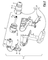
Figure 1 is a side elevation view of an exemplary power tool constructed in accordance with the present invention; -
Figure 2 is an exploded perspective view of the power tool ofFigure 1 ; -
Figure 3 is a longitudinal section view of a portion of the power tool ofFigure 1 illustrating the chuck in more detail; -
Figure 4 is an exploded perspective view of a portion of the power tool ofFigure 1 illustrating a locking mechanism in more detail; -
Figures 5, 6 and 7 are top plan views of a portion of the power tool ofFigure 1 illustrating a first lock structure of the locking mechanism in a first pivot position, a second pivot position and a neutral position, respectively; and -
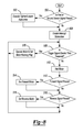
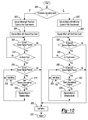
Figures 8 ,9 and10 are schematic illustrations in flow-chart form of a method in accordance with the present invention for controlling operation of the power tool ofFigure 1 . - Corresponding reference numerals indicate corresponding parts throughout the several views of the drawings.
- With reference to
Figures 1 and2 , a power tool constructed in accordance with the present invention is generally indicated byreference numeral 10. Thepower tool 10 can comprise atool portion 12, achuck 14 and alocking mechanism 16. - The
tool portion 12 can be any type of tool having a rotary output that is suited to drive thechuck 14, such as a hammer/drill driver, a rotary impact/driver or a hammer/rotary impact/driver. In the particular example provided, thetool portion 12 is a drill/driver. Exemplary drill/drivers are disclosed inU.S. Patent No. 6,431,289 andU.S. Patent Application Publication No. 2010/0163261 . Briefly, thetool portion 12 can comprise ahousing 20, amotor 22, atrigger assembly 24, a transmission 26, a clutch assembly 28, and anoutput spindle 30. - The
housing 20 can be formed of two or more components that can cooperate to define an internal cavity into which themotor 22, thetrigger assembly 24, the transmission 26 and the clutch assembly 28 can be housed. In the example provided, thehousing 20 comprises a pair ofmating handle shells 34 and agear case 36 that is mounted to the front of thehandle shells 34. - The
motor 22 can comprise anoutput member 40 that can input rotary power to the transmission 26. Themotor 22 can be any type of electric or fluid-powered motor, but in the example provided, is a brushed DC electric motor. Thetrigger assembly 24 can couple themotor 22 to a source of electrical power, such as a battery pack (not shown). Thetrigger assembly 24 can comprise atrigger controller 50, atrigger switch 52 and atrigger direction switch 54. Thetrigger controller 50 can conventionally direct power from the source of electrical power to themotor 22 in response to signals received from thetrigger switch 52 and thetrigger direction switch 54. - The transmission 26 can be any type of transmission that can be employed to provide a speed reduction and torque multiplication function. In the particular example provided, the transmission 26 is a three-stage, three-speed transmission. It will be appreciated, however, that the transmission 26 may include more or fewer stages, and may be configured to provide more or fewer speed ratios. The clutch assembly 28 can be configured to limit rotary power that is transmitted between the transmission 26 and the
output spindle 30. In the particular example provided, theoutput spindle 30 is coupled to an output member of the transmission 26 (i.e., a planet carrier in the final or output stage) for rotation therewith and the clutch assembly 28 is configured to limit rotary power transmitted through the transmission 26 to the output member. It will be appreciated that the clutch assembly 28 could be disposed between the output member of the transmission 26 and theoutput spindle 30 in the alternative. - With reference to
Figures 2 and3 , thechuck 14 can be any type of keyed or key-less chuck that is suited for use with thetool portion 12. In the particular example provided, thechuck 14 is a keyless chuck and except as described herein can be somewhat similar to the chuck that is disclosed inU.S. Patent No. 5,253,879 . Briefly, thechuck 14 can comprise achuck body 60, a plurality ofjaws 62, anouter sleeve 64, a split-nut 66, athrust ring 68, a plurality of bearingelements 70, aspring 72, a retainingring 74 and aback plate 76. - The
chuck body 60 can be a generally cylindrical structure having acentral cavity 80 and a plurality ofjaw apertures 82 that are configured to receive thejaws 62. Thecentral cavity 80 can include afirst cavity portion 86 and a second cavity portion 88. Thefirst cavity portion 86 can include a female threadedportion 90 that can be sized to threadably engagemating threads 92 formed on theoutput spindle 30 of thetool portion 12 such that thechuck body 60 and theoutput spindle 30 are coupled to one another for common rotation. The second cavity portion 88 can be configured to receive a bit (not shown) between thejaws 62. Theouter sleeve 64 is rotatably received over thechuck body 60. The split-nut 66 has a plurality ofthreads 94 that are threadably engaged to threadedsurfaces 96 on thejaws 62. The split-nut 66 can be coupled to theouter sleeve 64 for common rotation and in the particular example provided, the split-nut 66 is press-fit into theouter sleeve 64. Thethrust ring 68 is axially slidably received into theouter sleeve 64. The bearingelements 70 can be disposed between thethrust ring 68 and the split-nut 66. In the particular example provided, the bearingelements 70 comprise bearing balls. The retainingring 74 can be received in aring groove 100 formed in theouter sleeve 64. Thespring 72 can be employed to bias thethrust ring 68 toward the split-nut 66. In the example provided, thespring 72 comprises a Belleville spring washer that is abutted against the retainingring 74 and thethrust ring 68. Theback plate 76 can be configured to close a portion of theouter sleeve 64 that is disposed radially between theouter sleeve 64 and thechuck body 60. In the particular example provided, theback plate 76 is fixedly coupled to thechuck body 60 for rotation therewith. - With reference to
Figures 2 and4 , thelocking mechanism 16 can be received between thehousing 20 of thetool portion 12 and thechuck 14. Thelocking mechanism 16 can comprise alock base 120, afirst lock structure 122, asecond lock structure 124, one or more biasing springs 126, anactuating lever 128, amechanism control system 130 and alock housing 132. - The
lock base 120 can be fixedly coupled to thegear case 36 and can be disposed about theoutput spindle 30. Alternatively, thelock base 120 can be unitarily formed with thegear case 36. - The
first lock structure 122 can comprise acollar 140 and a set of first locking features 142. Thecollar 140 can be received over theoutput spindle 30 and can be pivotally coupled to thelock base 120 such that at least one side of thecollar 140 can be selectively pivoted about apivot axis 146 toward thechuck 14. In the particular example provided, thefirst lock structure 122 may be pivoted between a first pivot position (in which a first side of thecollar 140 is pivoted toward the chuck 14), a second pivot position (in which a second, opposite side of thecollar 140 is pivoted toward the chuck 14), and a neutral position (in which neither side of thecollar 140 is pivoted toward the chuck 14). The set of first locking features 142 can comprise a pair of first lockingteeth 148 that are disposed on opposite sides of thecollar 140 along atilt axis 150. - With reference to
Figures 3 and4 , thesecond lock structure 124 can comprise a set of second locking features 152 and can be fixedly coupled to theouter sleeve 64 of thechuck 14. In the particular example provided, the set of second locking features 152 comprises a second locking tooth 158 that are formed in alock plate 160 that is fixedly coupled (e.g., welded) to the rearaxial end 162 of theouter sleeve 64. The second locking tooth 158 can be configured to contact one of thefirst locking teeth 148 when one of the sides of thecollar 140 is pivoted toward thechuck 14. It will be appreciated, however, that the second locking features 152 could be integrally and unitarily formed with theouter sleeve 64, and/or that the second locking features 152 could comprise one or more tooth recesses (not shown) that are configured to receive thefirst locking teeth 148 when one of the sides of thecollar 140 is pivoted toward thechuck 14. - The one or more biasing springs 126 can be configured to bias the
first lock structure 122 into the neutral position where thecollar 140 is disposed concentrically about theoutput spindle 30 and thetilt axis 150 is perpendicular to therotational axis 166 of theoutput spindle 30. In the particular example provided, the one or more biasing springs 126 comprises a pair of compression springs that are received between thelock base 120 and thecollar 140 and each of the compression springs is configured to apply a force to thecollar 140 at a point along thetilt axis 150. - The
actuating lever 128 can be pivotally mounted to thelock base 120 and can be employed to pivot thefirst lock structure 122 about thepivot axis 146. In the particular example provided, theactuating lever 128 is movable between a first actuating position, an intermediate position, and a second actuating position. - With reference to
Figure 5 , when theactuating lever 128 is in the first actuating position, thefirst lock structure 122 is pivoted about thepivot axis 146 such that thefirst locking tooth 148 on the first side of thecollar 140 is positioned in the rotational path of the second locking features 152. Because pivoting thefirst lock structure 122 about thepivot axis 146 into the first actuating position rotates thetilt axis 150 about thepivot axis 146 such that thetilt axis 150 is not perpendicular to therotational axis 166 of the output spindle 30 (Fig. 2 ), and because thefirst locking teeth 148 are disposed along thetilt axis 150, it will be appreciated that thefirst locking tooth 148 on the second side of thecollar 140 will move away from thechuck 14 as thefirst locking tooth 148 on the first side of thecollar 140 moves toward thechuck 14. Accordingly, thelocking mechanism 16 is configured such that only one of thefirst locking teeth 148 will contact the second locking tooth 158 when theactuating lever 128 is positioned in the first actuating position. - With reference to
Figure 6 , when theactuating lever 128 is in the second actuating position, thefirst lock structure 122 is pivoted about thepivot axis 146 such that thefirst locking tooth 148 on the second side of thecollar 140 is positioned in the rotational path of the second locking features 152. Because pivoting thefirst lock structure 122 about thepivot axis 146 into the first actuating position rotates thetilt axis 150 about thepivot axis 146 such that thetilt axis 150 is not perpendicular to therotational axis 166 of the output spindle 30 (Fig. 2 ), and because thefirst locking teeth 148 are disposed along thetilt axis 150, it will be appreciated that thefirst locking tooth 148 on the first side of thecollar 140 will move away from thechuck 14 as thefirst locking tooth 148 on the second side of thecollar 140 moves toward thechuck 14. Accordingly, thelocking mechanism 16 is configured such that only one of thefirst locking teeth 148 will contact the second locking tooth 158 when theactuating lever 128 is positioned in the second actuating position. - With reference to
Figure 7 , when theactuating lever 128 is positioned in the intermediate position, thefirst lock structure 122 is positioned such that none of thefirst locking teeth 148 are positioned in the rotational path of the second locking tooth 158. - Returning to
Figure 4 , themechanism control system 130 can comprise one or more sensors, such as afirst sensor 200 and asecond sensor 202, and alock controller 204. The one or more sensors can be employed to generate a signal that is indicative of whether thechuck 14 is to be loosened or tightened. For example, the first andsecond sensors locking mechanism 16, such as thefirst lock structure 122 or theactuating lever 128. In the example provided: thefirst sensor 200 generates a first sensor signal in response to contact between the actuatinglever 128 and thefirst sensor 200 when theactuating lever 128 is in the first actuating position; and thesecond sensor 202 generates a second sensor signal in response to contact between the actuatinglever 128 and thesecond sensor 202 when theactuating lever 128 is in the second actuating position. Theactuating lever 128 need not contact thesecond sensor 202 when theactuating lever 128 is in the first actuating position or the intermediate position, and theactuating lever 128 need not contact thefirst sensor 200 when theactuating lever 128 is in the second actuating position or the intermediate position. - The
lock controller 204 can be configured to receive the first and second sensor signals and to responsively control the operation of the motor 22 (either directly, or through the trigger controller 50). For example, thelock controller 204 could be configured to transmit a control signal to thetrigger controller 50 to cause thetrigger controller 50 to control the operation of themotor 22 according to one or more predetermined control schemes. A control scheme may include, for example, a rotational direction of themotor 22, a rotational speed of themotor 22, and/or additional control parameters, such as a maximum time of operation of themotor 22. It will be appreciated that the control scheme for controlling themotor 22 when loosening thechuck 14 may be different from the control scheme for controlling themotor 22 when tightening thechuck 14. For example, the control scheme for operating themotor 22 to loosen thechuck 14 may be configured to cause themotor 22 to develop a relatively higher amount of torque than the control scheme for operating themotor 22 to tighten thechuck 14 due to differences between static and dynamic friction. It will also be appreciated that input from thetrigger switch 52 and the trigger direction switch 54 may be ignored (by thetrigger controller 50 and/or the lock controller 204) when controlling themotor 22 according to a control scheme for loosening or tightening thechuck 14. - More sophisticated algorithms for tightening the
chuck 14 may include for example an additional control parameter that detects a sharp rise in the current level provided to themotor 22 as themotor 22 is rotated clockwise (the sharp rise may be indicative of contact between thejaws 62 of thechuck 14 and a tool bit (not shown) received between the jaws 62). If desired, the additional control parameters may further include the provision of a short pulse of higher voltage power (e.g., through the use of a higher duty cycle in a pulse-width modulated power supply in the trigger controller 50) after the detection of the sharp rise in the current level provided to themotor 22 to cause themotor 22 to provide an increased amount of torque (to tighten thechuck 14 to a desired extent), after which power to themotor 22 can be interrupted. - More sophisticated algorithms for loosening the
chuck 14 may include for example the detection of a sharp rise in the current level provided to themotor 22 as themotor 22 is rotated counterclockwise (the sharp rise in current may be indicative of the engagement of the first and second locking features 142 and 152), and thereafter providing a short pulse of higher voltage power (e.g., through the use of a higher duty cycle in a pulse-width modulated power supply in the trigger controller 50) to cause themotor 22 to provide an increased amount of torque (to release thejaws 62 from the bit (not shown) in the chuck 14). Another set of additional parameters may be employed to detect a second sharp rise in the current provided to themotor 22 as themotor 22 is rotated counterclockwise (which could be indicative of the movement of thejaws 62 into a fully opened position) and to thereafter interrupt the supply of power to themotor 22. - With reference to
Figures 4 and8 , a method for controlling themotor 22 that coordinates control of themotor 22 responsive to thetrigger switch 52, thetrigger direction switch 54 and the first andsecond sensors decision block 500, control can proceed to block 504 to enable an interrupt subroutine so that the interrupt subroutine can operate concurrently with the control ofFigure 8 . Control can proceed to decision block 506 where a value of a trigger signal generated by thetrigger switch 52 is compared with a predetermined threshold. If the value of the trigger signal is greater than the predetermined threshold, control can proceed to block 508 where a duty cycle for the supply of electrical power via a pulse-width modulation in accordance with the trigger signal is employed to provide electrical power to the motor 22 (to operate the motor 22) and a motor running flag is set. Control can loop back todecision block 506. Returning to decision block 506, if the value of the trigger signal is not greater than the predetermined threshold, control can proceed to block 510 where control halts operation of the motor 22 (e.g., by interrupting the supply of electrical power to the motor 22). Control can proceed to decision block 512 where control determines if a trigger direction signal generated by the trigger direction switch 54 is indicative of a forward switch setting. If the trigger direction signal is indicative of the forward switch setting, control can proceed to block 514 where control sets a forward mode. Control can then proceed todecision block 516. Returning to decision block 512, if the trigger direction signal is not indicative of the forward switch setting, control can proceed to decision block 516, where control determines if the trigger direction signal generated by the trigger direction switch 54 is indicative of a reverse switch setting. If the trigger direction signal is indicative of the reverse switch setting, control can proceed to block 518 where control sets a reverse mode. Control can them loop back todecision block 506. Returning to decision block 516, if the trigger direction signal is not indicative of the reverse switch setting, control can loop back todecision block 506. - In
Figure 9 , the interrupt subroutine is illustrated. With reference toFigures 4 and9 , control can proceed to block 520 where control determines if the motor flag has been set (i.e., if themotor 22 is operating). If the motor flag has not been set, control proceeds to block 522 to execute the tighten/loosen subroutine (discussed in more detail below). If the motor flag has been set indecision block 520, control proceeds to block 524, where control halts the operation of themotor 22 and clears the motor running flag. Control proceeds to decision block 526, where control compares the value of a trigger signal generated by thetrigger switch 52 with a predetermined threshold. If the value of the trigger signal is greater than the predetermined threshold, control can loop back todecision block 526. If the value of the trigger signal is not greater than the predetermined threshold, control can proceed to decision block 528 where control determines if the first sensor signal or the second sensor signal is present. If the first sensor signal or the second sensor signal is present, control can loop back todecision block 528. If neither the first sensor signal nor the second sensor signal is present indecision block 528, control can proceed to block 530 where the interrupt subroutine can terminate. - In
Figure 10 , the tighten/loosen subroutine is illustrated. With reference toFigures 4 and10 , control can proceed to decision block 600 where control determines an operational mode for operating the power tool 10 (Fig. 1 ) based on the first and second sensor signals. If the first sensor signal is present and the second sensor signal is not present, the operational mode of the power tool 10 (Fig. 1 ) can be a tightening mode and control can proceed to block 602 where a first duty cycle (e.g., 40%) for the supply of electrical power via a pulse-width modulation is employed to provide electrical power to the motor 22 (to operate the motor 22) for a first time interval (e.g., 100 ms). When the first time interval elapses, control can proceed to block 604, where a second duty cycle (e.g., 20%) can be employed to provide electrical power to the motor 22 (to operate the motor 22). The second duty cycle can be selected to operate themotor 22 at a relatively lower speed. Control can proceed to decision block 606, where control determines if the first sensor signal is present. If the first sensor signal is not present, control can proceed to block 608 where themotor 22 is halted (e.g., by interrupting electric power to the motor 22). Control can proceed to block 610, where the tighten/loosen subroutine is terminated. Returning to decision block 606, if control determines that the first sensor signal is present, control can proceed to decision block 612 where control can determine if thechuck 14 is tight. Various techniques can be employed to determine if thechuck 14 is tight. For example, control can determine if the current (i) associated with the electric power that is supplied to themotor 22 exceeds a predetermined current threshold (Ti) or if a change in the current over time (di/dt) exceeds a predetermined rate (Ri). If thechuck 14 is not tight, control can loop back todecision block 606. If control determines that thechuck 14 is tight indecision block 612, control can proceed to decision block 614 where control determines if the first sensor signal is present. If the first sensor signal is not present, control can proceed to block 608. If the first sensor signal is present indecision block 614, control can proceed to decision block 616, where control can determine if a second time interval has elapsed. The second time interval can start to run when tighten/loosen subroutine initiates operation of the motor in the vibration mode in block 620 (discussed in more detail below). If the second time interval has elapsed, control can proceed to block 618, where operation of the motor is halted. Control can loop back todecision block 614. Returning to decision block 616, if the second time interval has not elapsed, control can proceed to block 620, where themotor 22 can be operated in a vibration mode. In the particular example provided, the vibration mode comprises alternating power input to themotor 22 between a forward direction at a third duty cycle (e.g., 20%) for a third time interval (e.g., 15 ms) and a reverse direction at a fourth duty cycle (e.g., 20%) for a fourth time interval (e.g., 15 ms). Control can loop back todecision block 614. It will be appreciated that the vibration mode is intended to provide feedback to the operator of thepower tool 10 that indicates that thechuck 14 is tight. It will be appreciated that other forms of alerts or alarms, including lights and/or sounds, could be used in addition to or in lieu of the vibration mode. - Returning to decision block 600, If the first sensor signal is not present and the second sensor signal is present, the operational mode of the power tool 10 (
Fig. 1 ) can be a loosening mode and control can proceed to block 622 where a fifth duty cycle (e.g., 55%) for the supply of electrical power via a pulse-width modulation is employed to provide electrical power to the motor 22 (to operate the motor 22) for a fifth time interval (e.g., 100 ms). When the fifth time interval elapses, control can proceed to block 624, where a sixth duty cycle (e.g., 20%) can be employed to provide electrical power to the motor 22 (to operate the motor 22). The sixth duty cycle can be selected to operate themotor 22 at a relatively lower speed. Control can proceed to decision block 626, where control determines if the second sensor signal is present. If the second sensor signal is not present, control can proceed to block 608 where operation of themotor 22 is halted. Returning to decision block 626, if control determines that the second sensor signal is present, control can proceed to decision block 628 where control can determine if thechuck 14 is loose. Various techniques can be employed to determine if thechuck 14 is loose. For example, control can determine if the current (i) associated with the electric power that is supplied to themotor 22 exceeds a predetermined current threshold (T2i) or if a change in the current over time (di/dt) exceeds a predetermined rate (R2i). If thechuck 14 is not loose, control can loop back todecision block 626. If control determines that thechuck 14 is loose indecision block 628, control can proceed to decision block 630, where control determines if the second sensor signal is present. If the second sensor signal is not present, control can proceed to block 608 where operation of themotor 22 is halted. Returning to decision block 630, if control determines that the second sensor signal is present, control can proceed to decision block 632 where control can determine if a sixth time interval has elapsed. The sixth time interval can start to run when tighten/loosen subroutine initiates operation of the motor in the vibration mode in block 636 (discussed in more detail below). If the sixth time interval has elapsed, control can proceed to block 634, where operation of the motor is halted. Control can loop back todecision block 630. Returning to decision block 632, if the sixth time interval has not elapsed, control can proceed to block 636 where themotor 22 can be operated in the vibration mode. In the particular example provided, the vibration mode comprises alternating power input to themotor 22 between the forward direction at the third duty cycle (e.g., 20%) for the third time interval (e.g., 15 ms) and the reverse direction at the fourth duty cycle (e.g., 20%) for the fourth time interval (e.g., 15 ms). Control can loop back todecision block 630. It will be appreciated that the vibration mode is intended to provide feedback to the operator of thepower tool 10 that indicates that thechuck 14 is loose. It will be appreciated that other forms of alerts or alarms, including lights and/or sounds, could be used in addition to or in lieu of the vibration mode - While the
lock controller 204 has been described as being separate and discrete from thetrigger controller 50 for purposes of this discussion, those of skill in the art will appreciate that thelock controller 204 and thetrigger controller 50 could be a single controller. - With reference to
Figures 2 and4 , thelock housing 132 can be configured to shroud thelock base 120, thefirst lock structure 122, thesecond lock structure 124, the one or more biasing springs 126 and some or all of themechanism control system 130. Thelock housing 132 can be an annular structure that can be fixedly coupled to thegear case 36. - While the
locking mechanism 16 has been illustrated and described as being permanently mounted to thetool portion 12, it will be appreciated that thelocking mechanism 16 may be utilized in a system of tools having removable heads. Such removable tool head systems are disclosed inU.S. Patent Nos. 7,021399 ;6,634,439 ; and6,675,911 . Additionally, the removable tool head may comprise electrical contacts that permit the removable tool head to communicate with the trigger controller to control the motor in an appropriate manner. - It will also be appreciated that while the
locking mechanism 16 has been illustrated and described as having a pivotingactuating lever 128 that is directly actuatable by the user of thepower tool 10, theactuating lever 128 could be manipulated in the alternative via a collar (not shown) that is pivotally mounted to thetool portion 12. Pivoting or partially rotating the collar in a first rotational direction can cause pivoting of theactuating lever 128 in a first direction, while pivoting or partially rotating the collar in a second, opposite rotational direction can cause pivoting of theactuating lever 128 is a second opposite direction. One or more springs associated with the collar or theactuating lever 128 could be employed to return the collar to a neutral position. - The foregoing description of the embodiments has been provided for purposes of illustration and description. It is not intended to be exhaustive. Individual elements or features of a particular embodiment are generally not limited to that particular embodiment, but, where applicable, are interchangeable and can be used in a selected embodiment, even if not specifically shown or described.
Claims (16)
- A power tool comprising:a tool portion having a housing, a motor disposed in the housing, and an output spindle driven by the motor;a chuck having a chuck body, which is coupled to the output spindle for rotation therewith, and a sleeve that is disposed about and rotatable relative to the chuck body; anda locking mechanism having a first lock structure and a second lock structure, the first lock structure being pivotally coupled to the housing about a pivot axis and having a first locking feature, the second lock structure having a second locking feature and being coupled to the sleeve for rotation therewith, wherein the first lock structure can be pivoted into a first pivot position in which the first locking feature is disposed in a rotational path of the second locking feature, and wherein engagement of the first and second locking features inhibits rotation of the sleeve so that rotation of the output spindle will cause corresponding rotation of the chuck body relative to the sleeve.
- The power tool of Claim 1, wherein the chuck further comprises a plurality of jaws that are received in corresponding holes formed in the chuck body.
- The power tool of Claim 1 or Claim 2, wherein the first locking feature comprises a locking tooth.
- The power tool of any preceding claim, wherein the second locking feature comprises a locking tooth.
- The power tool of any preceding claim, wherein the locking mechanism further comprises an actuator for pivoting the first lock structure.
- The power tool of Claim 5, wherein the actuator is a lever.
- The power tool of Claim 5 or Claim 6, further comprising at least one sensor for sensing a position of the actuator or the first lock structure when the first lock structure is positioned in the first pivot position.
- The power tool of Claim 7, wherein the at least one sensor comprises a limit switch.
- The power tool of any preceding claim, further comprising a controller for controlling operation of the motor when the first lock structure is positioned in the first pivot position.
- The power tool of Claim 9, further comprising at least one sensor for generating a first sensor signal in response to positioning of the first lock structure in the first pivot position, the controller receiving the first sensor signal and responsively controlling the motor according to a first control scheme.
- The power tool of Claim 10, wherein the first control scheme includes a motor rotational direction and a parameter that is indicative of a maximum motor torque.
- The power tool of Claim 11, wherein the parameter is a duty cycle for a pulse-width modulated power supply.
- The power tool of Claim 11 or Claim 12, wherein the first control scheme is configured to change operation of the motor in response to a predetermined rise in current to the motor.
- The power tool of Claim 13, wherein the controller halts operation of the motor in response to the predetermined rise in current to the motor.
- The power tool of Claim 13, wherein the controller operates the motor to provide a higher output torque in response to the predetermined rise in current to the motor.
- The power tool of any preceding claim, wherein the locking mechanism further comprises at least one biasing spring for biasing the first lock structure into a neutral position in which the first locking feature cannot be engaged to the second locking feature.
Applications Claiming Priority (1)
| Application Number | Priority Date | Filing Date | Title |
|---|---|---|---|
| US13/453,251 US9259790B2 (en) | 2012-04-23 | 2012-04-23 | Power tool with automatic chuck |
Publications (2)
| Publication Number | Publication Date |
|---|---|
| EP2656951A2 true EP2656951A2 (en) | 2013-10-30 |
| EP2656951A3 EP2656951A3 (en) | 2016-04-06 |
Family
ID=48143528
Family Applications (1)
| Application Number | Title | Priority Date | Filing Date |
|---|---|---|---|
| EP13164820.6A Withdrawn EP2656951A3 (en) | 2012-04-23 | 2013-04-23 | Power tool with automatic chuck |
Country Status (2)
| Country | Link |
|---|---|
| US (2) | US9259790B2 (en) |
| EP (1) | EP2656951A3 (en) |
Families Citing this family (8)
| Publication number | Priority date | Publication date | Assignee | Title |
|---|---|---|---|---|
| US9259790B2 (en) * | 2012-04-23 | 2016-02-16 | Black & Decker Inc. | Power tool with automatic chuck |
| DE202013101255U1 (en) * | 2013-03-25 | 2013-04-10 | Röhm Gmbh | chuck |
| US10512971B2 (en) * | 2013-08-28 | 2019-12-24 | Positec Power Tools (Suzhou) Co., Ltd. | Power tool and operation method for quick locking and releasing working attachment thereof |
| CN106393007B (en) * | 2015-07-31 | 2019-06-14 | 南京德朔实业有限公司 | Torque output tool and its accessories |
| WO2018068284A1 (en) | 2016-10-14 | 2018-04-19 | Jacobs Chuck Manufacturing (Suzhou) Company, Ltd. | Chuck with slip protection |
| WO2019019165A1 (en) * | 2017-07-28 | 2019-01-31 | Jacobs Chuck Manufacturing (Suzhou) Company, Ltd. | Locking chuck with anti-vibration feature |
| JP7618683B2 (en) * | 2020-02-17 | 2025-01-21 | ミルウォーキー エレクトリック ツール コーポレイション | Electronic Spindle Lock for Power Tools |
| EP4204173A4 (en) * | 2020-10-09 | 2024-09-11 | Apex Brands, Inc. | POWER TOOL WITH LIFT-OFF PROTECTION |
Citations (6)
| Publication number | Priority date | Publication date | Assignee | Title |
|---|---|---|---|---|
| US5253879A (en) | 1989-12-11 | 1993-10-19 | Jacobs Chuck Technology Corporation | Non-impact keyless chuck |
| US6431289B1 (en) | 2001-01-23 | 2002-08-13 | Black & Decker Inc. | Multi-speed power tool transmission |
| US6634439B2 (en) | 2000-03-10 | 2003-10-21 | Black & Decker Inc. | Interlock mechanism |
| US6675911B2 (en) | 2000-03-10 | 2004-01-13 | Black & Decker Inc. | Coupling mechanism |
| US7021399B2 (en) | 2000-03-10 | 2006-04-04 | Black & Decker Inc. | Power tool |
| US20100163261A1 (en) | 2008-11-08 | 2010-07-01 | Tomayko David C | Multi-speed power tool transmission with alternative ring gear configuration |
Family Cites Families (47)
| Publication number | Priority date | Publication date | Assignee | Title |
|---|---|---|---|---|
| US2716555A (en) * | 1953-08-19 | 1955-08-30 | Walker E Rowe | Power operated chuck device |
| US3237955A (en) * | 1964-01-03 | 1966-03-01 | Jacobs Mfg Co | Keyless chuck |
| DE2933355A1 (en) * | 1979-08-17 | 1981-03-26 | Scintilla Ag, Solothurn | ELECTRIC HAND TOOL |
| US4317578A (en) * | 1979-11-07 | 1982-03-02 | Welch Thomas R | Keyless chucking system |
| US4307325A (en) * | 1980-01-28 | 1981-12-22 | Black & Decker Inc. | Digital control system for electric motors in power tools and the like |
| US4412158A (en) * | 1980-02-21 | 1983-10-25 | Black & Decker Inc. | Speed control circuit for an electric power tool |
| US4317176A (en) * | 1980-03-24 | 1982-02-23 | Black & Decker Inc. | Microcomputer controlled power tool |
| US4358230A (en) * | 1980-04-04 | 1982-11-09 | Rohlin Robert W | Chuck operating device for hand drill |
| US4526497A (en) | 1982-03-15 | 1985-07-02 | Hatfield Jim J | Automatic jaw control for reversible power tool |
| US4540318A (en) * | 1982-07-29 | 1985-09-10 | Robert Bosch, Gmbh | Rotary electrical tool with speed control, especially drill |
| IT1212535B (en) * | 1982-10-26 | 1989-11-30 | Star Utensili Elett | ELECTRONIC CLUTCH WITH MULTIPLE LEVEL OF INTERVENTION FOR ELECTRIC TOOLS WITH SPEED SELECTABLE. |
| US4915555A (en) * | 1989-06-07 | 1990-04-10 | Smothers Clarence W | Power drill having drill chuck tightener |
| EP0426899A1 (en) * | 1989-11-10 | 1991-05-15 | Shilban Ltd. | Improvements in drills |
| IT1272025B (en) * | 1993-03-15 | 1997-06-10 | Riccardo Pedrotti | EQUIPMENT FOR TIGHTENING AND / OR DE-LOCKING OF TOOLS IN A SPINDLE. |
| US6424799B1 (en) * | 1993-07-06 | 2002-07-23 | Black & Decker Inc. | Electrical power tool having a motor control circuit for providing control over the torque output of the power tool |
| GB9320181D0 (en) * | 1993-09-30 | 1993-11-17 | Black & Decker Inc | Improvements in and relating to power tools |
| US6479958B1 (en) * | 1995-01-06 | 2002-11-12 | Black & Decker Inc. | Anti-kickback and breakthrough torque control for power tool |
| DE19508925A1 (en) * | 1995-03-13 | 1996-09-19 | Marquardt Gmbh | Electrical switch, in particular for electrical hand tools |
| DE19609986A1 (en) * | 1995-03-24 | 1996-09-26 | Marquardt Gmbh | Method of operating an electric motor, esp. for electric hand tool, e.g. drill, |
| JP3677416B2 (en) * | 1998-10-23 | 2005-08-03 | 株式会社森精機ハイテック | Electric chuck control method and apparatus |
| US5988957A (en) | 1998-12-21 | 1999-11-23 | Black & Decker Inc. | Quick clamp |
| US6536536B1 (en) * | 1999-04-29 | 2003-03-25 | Stephen F. Gass | Power tools |
| US6241260B1 (en) | 1999-08-17 | 2001-06-05 | Black & Decker Inc. | Spring-loaded quick clamp chuck |
| EP1867438A3 (en) * | 2000-11-17 | 2009-01-14 | Makita Corporation | Impact power tools |
| AUPR272101A0 (en) | 2001-01-24 | 2001-02-22 | Bayly Design Associates Pty Ltd | Power tool |
| ITMI20030666A1 (en) * | 2003-04-04 | 2004-10-05 | Univer Spa | ELECTRIC LOCKING EQUIPMENT WITH MANUAL CONTROL |
| US7360770B2 (en) | 2004-08-17 | 2008-04-22 | Black & Decker Inc. | Keyless chuck with automatic and manual locking |
| US7331584B2 (en) | 2004-09-17 | 2008-02-19 | Black & Decker Inc. | Chuck with nutating gear reduction |
| CN101934386A (en) | 2004-09-27 | 2011-01-05 | 布莱克和戴克公司 | Tool chuck with sleeve and clutch mechanism to remove operator variability |
| US7243923B2 (en) | 2005-02-09 | 2007-07-17 | Black & Decker Inc. | Centering drill chuck |
| US7520512B2 (en) | 2005-02-18 | 2009-04-21 | Black & Decker Inc. | Drill chuck |
| US7503734B2 (en) | 2005-02-18 | 2009-03-17 | Black & Decker Inc. | Drill chuck actuator |
| US20060185870A1 (en) | 2005-02-18 | 2006-08-24 | Black & Decker Inc. | Drill chuck |
| US7491020B2 (en) | 2005-02-18 | 2009-02-17 | Black & Decker Inc. | Three position selector for automated chuck |
| US7328904B2 (en) | 2005-04-19 | 2008-02-12 | Black & Decker Inc. | Power tool with power-take-off driven pusher-type chuck having device for reducing tension in pusher screw |
| US7677844B2 (en) * | 2005-04-19 | 2010-03-16 | Black & Decker Inc. | Electronic clutch for tool chuck with power take off and dead spindle features |
| DE102005021629A1 (en) * | 2005-05-06 | 2006-11-09 | Röhm Gmbh | drilling |
| US20080134846A1 (en) * | 2005-05-25 | 2008-06-12 | Potempa Brian S | Tool assembly comprising handle including driver tool |
| CN101253015A (en) * | 2005-08-29 | 2008-08-27 | 迪美科技控股有限公司 | power tool |
| ATE476272T1 (en) | 2005-08-29 | 2010-08-15 | Demain Technology Pty Ltd | POWER OPERATED TOOL |
| US7537421B2 (en) | 2005-09-16 | 2009-05-26 | Black & Decker Inc. | Dead spindle PTO with compliant grounding mechanism |
| DE602006013863D1 (en) * | 2005-11-04 | 2010-06-02 | Bosch Gmbh Robert | METHOD AND DEVICE FOR A JOINT DRILL |
| US20120175142A1 (en) * | 2009-07-17 | 2012-07-12 | Demain Technology Pty Ltd. | Power tool |
| EP2305430A1 (en) * | 2009-09-30 | 2011-04-06 | Hitachi Koki CO., LTD. | Rotary striking tool |
| US9722334B2 (en) * | 2010-04-07 | 2017-08-01 | Black & Decker Inc. | Power tool with light unit |
| US8714566B2 (en) | 2010-09-27 | 2014-05-06 | Black & Decker Inc. | Tool chuck with indicator mechanism |
| US9259790B2 (en) * | 2012-04-23 | 2016-02-16 | Black & Decker Inc. | Power tool with automatic chuck |
-
2012
- 2012-04-23 US US13/453,251 patent/US9259790B2/en active Active
-
2013
- 2013-04-23 EP EP13164820.6A patent/EP2656951A3/en not_active Withdrawn
-
2016
- 2016-01-07 US US14/989,837 patent/US20160114408A1/en not_active Abandoned
Patent Citations (6)
| Publication number | Priority date | Publication date | Assignee | Title |
|---|---|---|---|---|
| US5253879A (en) | 1989-12-11 | 1993-10-19 | Jacobs Chuck Technology Corporation | Non-impact keyless chuck |
| US6634439B2 (en) | 2000-03-10 | 2003-10-21 | Black & Decker Inc. | Interlock mechanism |
| US6675911B2 (en) | 2000-03-10 | 2004-01-13 | Black & Decker Inc. | Coupling mechanism |
| US7021399B2 (en) | 2000-03-10 | 2006-04-04 | Black & Decker Inc. | Power tool |
| US6431289B1 (en) | 2001-01-23 | 2002-08-13 | Black & Decker Inc. | Multi-speed power tool transmission |
| US20100163261A1 (en) | 2008-11-08 | 2010-07-01 | Tomayko David C | Multi-speed power tool transmission with alternative ring gear configuration |
Also Published As
| Publication number | Publication date |
|---|---|
| US20130277923A1 (en) | 2013-10-24 |
| US20160114408A1 (en) | 2016-04-28 |
| EP2656951A3 (en) | 2016-04-06 |
| US9259790B2 (en) | 2016-02-16 |
Similar Documents
| Publication | Publication Date | Title |
|---|---|---|
| EP2656951A2 (en) | Power tool with automatic chuck | |
| EP2407274B1 (en) | Rotary impact tool | |
| EP1423223B1 (en) | Hammerlock chuck | |
| EP2246156B1 (en) | Power tool impact mechanism | |
| EP2722131B1 (en) | Hybrid impact tool | |
| US5601387A (en) | Depth adjusting system for a power tool | |
| US20070221022A1 (en) | Power tool | |
| EP3067156B1 (en) | Rotary impact tool | |
| US20230321796A1 (en) | Power tool with sheet metal fastener mode | |
| JP2008183643A (en) | Constant torque electric screwdriver | |
| US7249770B2 (en) | Locking drill chuck | |
| WO2014095472A2 (en) | Impulse wrench with push start feature | |
| US7503734B2 (en) | Drill chuck actuator | |
| JP5493272B2 (en) | Rotary impact tool | |
| WO2019054257A1 (en) | Fastening tool | |
| JP2011073087A (en) | Fastening machine tool | |
| US7520512B2 (en) | Drill chuck | |
| JP5674027B2 (en) | Tightening tool | |
| EP1559491B1 (en) | A power drill chuck | |
| WO2013078381A1 (en) | Chuck with jam release | |
| JP2014024166A (en) | Power tool and tip tool | |
| CN101166598A (en) | Drill fixture | |
| JP2015074075A (en) | Impact tool | |
| JP2005046922A (en) | Impact function limiting device |
Legal Events
| Date | Code | Title | Description |
|---|---|---|---|
| PUAI | Public reference made under article 153(3) epc to a published international application that has entered the european phase |
Free format text: ORIGINAL CODE: 0009012 |
|
| AK | Designated contracting states |
Kind code of ref document: A2 Designated state(s): AL AT BE BG CH CY CZ DE DK EE ES FI FR GB GR HR HU IE IS IT LI LT LU LV MC MK MT NL NO PL PT RO RS SE SI SK SM TR |
|
| AX | Request for extension of the european patent |
Extension state: BA ME |
|
| PUAL | Search report despatched |
Free format text: ORIGINAL CODE: 0009013 |
|
| AK | Designated contracting states |
Kind code of ref document: A3 Designated state(s): AL AT BE BG CH CY CZ DE DK EE ES FI FR GB GR HR HU IE IS IT LI LT LU LV MC MK MT NL NO PL PT RO RS SE SI SK SM TR |
|
| AX | Request for extension of the european patent |
Extension state: BA ME |
|
| RIC1 | Information provided on ipc code assigned before grant |
Ipc: B23B 31/12 20060101AFI20160226BHEP |
|
| STAA | Information on the status of an ep patent application or granted ep patent |
Free format text: STATUS: THE APPLICATION HAS BEEN PUBLISHED |
|
| STAA | Information on the status of an ep patent application or granted ep patent |
Free format text: STATUS: THE APPLICATION IS DEEMED TO BE WITHDRAWN |
|
| 18D | Application deemed to be withdrawn |
Effective date: 20161007 |