EP2656938A2 - Spinning method, spinning machine, and shaped component - Google Patents
Spinning method, spinning machine, and shaped component Download PDFInfo
- Publication number
- EP2656938A2 EP2656938A2 EP20130165096 EP13165096A EP2656938A2 EP 2656938 A2 EP2656938 A2 EP 2656938A2 EP 20130165096 EP20130165096 EP 20130165096 EP 13165096 A EP13165096 A EP 13165096A EP 2656938 A2 EP2656938 A2 EP 2656938A2
- Authority
- EP
- European Patent Office
- Prior art keywords
- tube material
- roller
- shape
- chucks
- tube
- Prior art date
- Legal status (The legal status is an assumption and is not a legal conclusion. Google has not performed a legal analysis and makes no representation as to the accuracy of the status listed.)
- Withdrawn
Links
- 238000000034 method Methods 0.000 title claims abstract description 73
- 238000009987 spinning Methods 0.000 title claims abstract description 60
- 239000000463 material Substances 0.000 claims abstract description 187
- 238000003825 pressing Methods 0.000 claims abstract description 19
- 238000012545 processing Methods 0.000 claims description 53
- 238000007493 shaping process Methods 0.000 claims description 47
- 238000004519 manufacturing process Methods 0.000 description 12
- 238000012986 modification Methods 0.000 description 11
- 230000004048 modification Effects 0.000 description 11
- 230000003247 decreasing effect Effects 0.000 description 8
- 238000010586 diagram Methods 0.000 description 8
- 238000007796 conventional method Methods 0.000 description 6
- 239000000047 product Substances 0.000 description 5
- 238000005520 cutting process Methods 0.000 description 3
- 230000000694 effects Effects 0.000 description 3
- 238000012546 transfer Methods 0.000 description 3
- 230000015572 biosynthetic process Effects 0.000 description 2
- 238000013461 design Methods 0.000 description 2
- 239000002184 metal Substances 0.000 description 2
- 230000002093 peripheral effect Effects 0.000 description 2
- 239000013589 supplement Substances 0.000 description 2
- 230000004075 alteration Effects 0.000 description 1
- 238000013459 approach Methods 0.000 description 1
- 238000009499 grossing Methods 0.000 description 1
- 239000007788 liquid Substances 0.000 description 1
- 239000007769 metal material Substances 0.000 description 1
- 230000003252 repetitive effect Effects 0.000 description 1
- 238000013000 roll bending Methods 0.000 description 1
- 230000009469 supplementation Effects 0.000 description 1
- 238000003466 welding Methods 0.000 description 1
Images








Classifications
-
- B—PERFORMING OPERATIONS; TRANSPORTING
- B21—MECHANICAL METAL-WORKING WITHOUT ESSENTIALLY REMOVING MATERIAL; PUNCHING METAL
- B21B—ROLLING OF METAL
- B21B17/00—Tube-rolling by rollers of which the axes are arranged essentially perpendicular to the axis of the work, e.g. "axial" tube-rolling
-
- B—PERFORMING OPERATIONS; TRANSPORTING
- B21—MECHANICAL METAL-WORKING WITHOUT ESSENTIALLY REMOVING MATERIAL; PUNCHING METAL
- B21D—WORKING OR PROCESSING OF SHEET METAL OR METAL TUBES, RODS OR PROFILES WITHOUT ESSENTIALLY REMOVING MATERIAL; PUNCHING METAL
- B21D22/00—Shaping without cutting, by stamping, spinning, or deep-drawing
- B21D22/14—Spinning
-
- B—PERFORMING OPERATIONS; TRANSPORTING
- B21—MECHANICAL METAL-WORKING WITHOUT ESSENTIALLY REMOVING MATERIAL; PUNCHING METAL
- B21D—WORKING OR PROCESSING OF SHEET METAL OR METAL TUBES, RODS OR PROFILES WITHOUT ESSENTIALLY REMOVING MATERIAL; PUNCHING METAL
- B21D22/00—Shaping without cutting, by stamping, spinning, or deep-drawing
- B21D22/14—Spinning
- B21D22/18—Spinning using tools guided to produce the required profile
-
- F—MECHANICAL ENGINEERING; LIGHTING; HEATING; WEAPONS; BLASTING
- F16—ENGINEERING ELEMENTS AND UNITS; GENERAL MEASURES FOR PRODUCING AND MAINTAINING EFFECTIVE FUNCTIONING OF MACHINES OR INSTALLATIONS; THERMAL INSULATION IN GENERAL
- F16L—PIPES; JOINTS OR FITTINGS FOR PIPES; SUPPORTS FOR PIPES, CABLES OR PROTECTIVE TUBING; MEANS FOR THERMAL INSULATION IN GENERAL
- F16L9/00—Rigid pipes
- F16L9/02—Rigid pipes of metal
-
- B—PERFORMING OPERATIONS; TRANSPORTING
- B21—MECHANICAL METAL-WORKING WITHOUT ESSENTIALLY REMOVING MATERIAL; PUNCHING METAL
- B21D—WORKING OR PROCESSING OF SHEET METAL OR METAL TUBES, RODS OR PROFILES WITHOUT ESSENTIALLY REMOVING MATERIAL; PUNCHING METAL
- B21D53/00—Making other particular articles
- B21D53/26—Making other particular articles wheels or the like
- B21D53/30—Making other particular articles wheels or the like wheel rims
Definitions
- the present invention relates to a spinning technique and others.
- Patent Document 1 Japanese Patent Application Laid-Open Publication No. S62-227520
- Patent Document 2 Japanese Patent No. 3455892
- the Patent Document 1 (“Method of Manufacturing Twist Deformed Tube”) describes "to provide a method, without using a core bar, of manufacturing a twist tapered tube or straight tube having different cross-sectional surfaces, which is formed so as to have an appearance of a twisted tube body by spirally forming a waved or polyhedral pattern on a tube outer peripheral surface in a tube longitudinal direction”, and describes "a method of manufacturing a twist deformed tube, in which a hollow cylindrical tube material is rolled while holding it at both ends and applying tensile force or compressing force thereto in an axial direction of the tube material, and besides, a shaping roll is moved in the axial direction of the tube material while pressing the shaping roll against the tube material, so that the tube material is shaped into a desired shape, with using a roll whose peripheral surface is formed into a waved shape or polyhedral shape as the shaping roll”.
- the Patent Document 2 (“Method of Manufacturing Step Rotating Body”) describes to manufacture a step rotating body with a light weight, without distortion, with excellent concentricity, with a uniform thickness, and with good rotational balance. Also, it describes a method of manufacturing a step rotating body formed of a boss portion and a cylindrical portion which is integrally formed with the boss portion and which has a larger diameter than that of the boss portion, the method in which both ends of a thin tubular material are fitted in a cylindrical-portion die, are engaged therewith in a diameter-increasing direction, and are pressed in an axial direction to be held, a diameter of an axial-direction intermediate portion of this tubular material is decreased by a shaping roll so that the portion follows a boss-portion die provided between the above-described tubular-portion dies opposite to each other, and then, this diameter-decreased portion is cut in the middle thereof in the axial direction so as to use a part fitted in the cylindrical-portion die as the cylindrical portion and use a part fitted in the boss
- Patent Document 1 describes the method of shaping the tube material into the predetermined shape by, in spinning of the tube material which is a cylindrical raw tube, rotating the tube material supported at both ends thereof (supported by tensile force or compressing force) and moving the shaping roll (also referred to as a roller) thereon in the axial direction or longitudinal direction of the tube material while pressing the shaping roll against the tube material.
- the spinning is performed only with the roller without using a mandrel which is a die arranged inside the tube material or in a core in order to transfer the predetermined shape onto an outer surface of the tube material.
- the mandrel (4) described in Patent Document 1 is described as an object for supporting the both ends of the tube material (1), and is not intended as the die which is arranged inside the above-described tube material or in the core in order to transfer the predetermined shape to the outer surface of the tube material.
- Patent Document 1 has a problem of reduction in working efficiency due to long processing time because the moving direction of the roller is the axial direction or longitudinal direction of the tube material.
- Patent Document 2 describes the shaping method in the spinning of the tube material which is the cylindrical raw tube, by moving the roller in a radial direction of the tube material while pressing the roller against the axial-direction intermediate portion of the tube material.
- the processing or diameter-decreasing shaping is performed with taking the feeding direction of the roller as the radial direction of the tube material.
- the mandrel is introduced.
- the method as described in Patent Document 2 has a problem of reduction in production efficiency because a step and working of detaching the tube material from the mandrel is required subsequent to the shaping.
- the shape of the tube material subsequent to the shaping is largely limited.
- the processing cannot be performed for such a shape that the diameter of the portion against which the roller is pressed to be the center portion of the tube material in the rotation-axis direction is larger than the diameter of the other portion such as the vicinity of the both ends of the tube material. This is because the tube material subsequent to the shaping cannot be detached from the mandrel or because cutting of the tube material subsequent to the shaping or others is required (see FIG. 12 described later or others).
- a main preferred aim of the present invention for a method of spinning a tube (pipe) material is to provide a technique capable of improving working efficiency with short processing time, achieving a flexible processed shape, and improving production efficiency. More particularly, it is to provide a technique capable of achieving the above-described effects by employing a method of moving a roller in a radial direction of the tube material without using the mandrel which is a die arranged inside the tube material in order to transfer a shape.
- a typical embodiment of the present invention is a method of spinning a tube material, a machine thereof, and others, and has a feature of a configuration described below.
- the spinning method according to the present embodiment uses components including: a tube material; a pair of chucks which hold and rotate both ends of the tube material; and a roller which is a rotating symmetrical body having a predetermined curved shape on a side surface thereof in order to shape the tube material.
- a mandrel or others is not arranged inside the tube material.
- the present method provides a state that circumferential portions at the both ends of the tube material are fitted in and held by circumferential grooves provided on respective side surfaces of a pair of chucks facing each other.
- the chucks holding the tube material are rotated around a first axis
- the roller is rotated around a second axis.
- the rotating axial directions of the first axis and the second axis are the same as each other as a first direction, and the radial direction thereof is a second direction.
- the present method includes a step of moving the rotating roller in the second direction and pressing a side surface of the roller against a side surface of the rotating tube material between the rotating chucks from outside, so that a curved shape of the side surface of the roller is transferred to the side surface of the tube material.
- a shape of the side surface of the roller is a concave curved shape which is concave in the second direction at a center thereof in the first direction, and a shape of the tube material or a tubular shaped component obtained subsequent to the shaping is formed into a portion having a convex curved shape which is convex in the second direction.
- each width of the grooves provided on the side surfaces of the chucks is designed to have a length obtained by addition of a thickness of an end portion of the tube material and a processing tolerance, and the processing tolerance is designed in consideration of margin upon fitting the end portion of the tube material into the grooves of the chucks and consideration of holding force upon the rotation.
- the working efficiency can be improved with short processing time, the flexible processed shape can be achieved, and the production efficiency can be improved.
- the working and processing time is shortened by taking the moving direction of the roller as the radial direction of the raw tube, so that the working efficiency can be improved.
- the spinning without using the mandrel can be achieved, and the detachment from the mandrel or others is unnecessary, so that the production efficiency can be improved.
- the present invention can achieve the processing or the shaping of the flexible shape including, for example, a shape of a tube material having a larger diameter at a center portion in a rotation-axis direction than those at both sides thereof in accordance with the shape of the roller, and besides, a thickness of the material obtained subsequent to the processing or the shaping is prevented from being decreased or is increased.
- FIG. 1 illustrates a configuration of a tube material 102, chucks 101 which are a tube-end holding tool, and a roller 103 in a spinning method and machine according to the present embodiment.
- “Z” is a rotation-axis direction
- "X” and “Y” are radial directions as illustrated in the drawing.
- the tube material 102 is a raw tube in other words, such as a hollow cylindrical metal material as also illustrated in FIG. 5 and others.
- the circumferences at both ends of the tube material 102 is held or restricted by grooves 104 ( FIG. 4 ) of chucks 101.
- the pair of tube-end holding tools 101 are chucks for holding or restricting the circumferences at the both ends of the tube material 102, and are made of, for example, columnar or disk-shaped metal.
- the tube-end holding tools 101 include a portion 101a on one side and a portion 101b on the other side which have similar configurations to each other, which are provided with the respective grooves 104 for entirely holding or restricting the circumferences at the ends of the tube material 102 as described later ( FIG. 4 ).
- the raw tube 102 is arranged between the pair of chucks 101 (101a and 101b), and the ends thereof are fitted in the grooves 104.
- the roller 103 is a shaping roller in other words, and is roughly a columnar rotating symmetrical body, and more specifically has a concave shape as a curved surface of a side surface thereof as illustrated in FIGs. 3 , 7 , and others.
- the tube material 102 and the chucks 101 are rotated around an axis J1.
- the roller 103 is rotated around an axis J2. Also, the roller 103 is moved in the radial direction (X) of the tube material 102 as illustrated by an arrow 401.
- FIG. 2 illustrates an overall configuration of the spinning machine 10 which is a system of the present embodiment in accordance with the spinning method of the present embodiment.
- the present spinning machine 10 performs spinning of the tube material 102, drive control of the spinning, and others.
- the present spinning machine 10 is configured to include: a controlling unit 11; a roller driving unit 12; a rotation driving unit 13; an axial-movement driving unit 14; rotating chucks 201a and 201b; a roller rotating chuck 202; and others, in which the chucks 101 and the raw tube 102 of FIG. 1 are set between the rotating chucks 201a and 201b, and the roller 103 is set at the roller rotating chuck 202.
- a shaft 202c of the roller rotating chuck 202 is detachable, and the roller 103 whose type depends on a desired shape in the shaping is attachable and detachable.
- the rotating chuck 201b is configured to be movable in the axial (Z) direction. In this manner, the chucks 101 and the tube material 102 are attachable and detachable between the rotating chucks 201a and 201b.
- One chuck 101a is fixed to one rotating chuck 201a, and the other chuck 101b is fixed to the other rotating chuck 201b.
- the rotating chuck 201a and the rotation driving unit 13 the rotation of the chucks 101 (101a and 101b) and the tube material 102 around the axis J1 is driven.
- roller driving unit 12 and the roller rotating chuck 202 rotation of the roller 103 around the axis J2 and movement thereof are driven.
- the movement of the roller 103 includes at least movement in the X direction, and is further configured that it is freely movable in the X, Y, and Z directions, so that more complex processing can be performed.
- the roller 103 Upon the processing, the roller 103 is moved in the radial (X) direction of the raw tube 102 as illustrated by the arrow 401 together with the rotation of the roller 103, and is caused to approach to and is pressed against an outer surface of the side surface of the raw tube 102 provided between the chucks 101a and 101b. In this manner, as illustrated in FIG. 3B , a desired shape is formed by transferring the concave shape which is the shape of the side surface of the roller 103 onto the outer surface of the side surface of the raw tube 102.
- the controlling unit 11 provides a control command to the roller driving unit 12, the rotation driving unit 13, the axial-movement driving unit 14, or others so as to control their driving.
- the controlling unit 11 can be configured by a publicly-known technique such as an IC chip or a calculator, and each of the driving units (12, 13, and 14) can be configured by a publicly-known technique such as a motor or others.
- Each of the rotating chucks (201a, 201b, and 202) can be also configured by a publicly-known technique.
- FIGs. 3A and 3B illustrate outlines of the spinning method of the present embodiment in cross-sectional views.
- FIG. 3A illustrates the chucks 101, the tube material 102, and the roller 103 in a state prior to the processing, and particularly illustrates a state in which the roller 103 is in contact with the tube material 102.
- FIG. 3B illustrates a shape/a state of a tube material 102' obtained subsequent to the processing in which the roller 103 has been moved in the radial (X) direction of the tube material 102 and been pushed in.
- the raw tube 102 is arranged between the tube-end holding tools 101 (101a and 101b) which are the pair of chucks arranged so as to face each other, and the circumferences at the both ends of the raw tube 102 are entirely fitted in the grooves 104 ( FIG. 4 ) of the respective chucks 101 and are held or restricted by them.
- the tube-end holding tools 101 101a and 101b
- the circumferences at the both ends of the raw tube 102 are entirely fitted in the grooves 104 ( FIG. 4 ) of the respective chucks 101 and are held or restricted by them.
- the roller 103 is arranged at a position outside the raw tube 102 on a line a-a between the chucks 101a and 101b.
- the line a-a represents an intermediate position of the tube material 102 and the roller 103 in Z direction.
- a symbol “P1” represents a width or a length of the roller 103 in the axial (Z) direction.
- a symbol “Q1” represents a distance between surfaces of the chucks 101a and 101b facing each other in the axial (Z) direction, in other words, a width of a portion against which the roller 103 can be pressed.
- spinning which shapes the tube material 102 into a desired shape can be performed so as to change from FIG. 3A to FIG. 3B by moving or feeding the roller 103 in the radial (X) direction of the tube material 102 as illustrated by the arrow 401 together with the rotation drive of the chucks 101, the tube material 102, and the roller 103 and pressing it.
- the roller 103 is moved to a predetermined position in the X direction and is pressed against the side surface of the tube material 102', so that the concave shape which is the shape of the side surface of the roller 103 is transferred onto the side surface of the tube material 102'.
- the shape of the tube material 102' subsequent to the shaping is a rotating symmetrical body around the axis J1. Note that a symbol "k1" represents an inner diameter of the convex portion of the tube material 102' and a symbol “k2" represents an inner diameter of the concave portion thereof obtained subsequent to the processing.
- the spinning of the tube material 102 that is, the transferring of the desired shape thereto can be performed without the usage of the mandrel which is the die arranged inside the tube material 102 and without the movement of the roller 103 in the axial (Z) direction of the tube material 102.
- the processing can be performed so as to form an outward-convex shape in the vicinity of the line a-a which is the center of the tube material 102' in the axial (Z) direction.
- FIG. 4A illustrates a cross-sectional surface of the chuck 101a in a Z-X plane (note that the chuck 101b is also similar), and FIG. 4B illustrates the enlarged grooves 104.
- FIG. 4C illustrates a state in which an end 406 of the tube material 102 is fitted in and held by the grooves 104.
- the circumferential groove 104 is provided on one side surface of the chuck 101a.
- the groove 104 can be provided by, for example, grooving a surface of a metal disk by cutting or others.
- the groove 104 is designed so as to have dimensions, positions, and shapes, which are equal to those of the outer diameter (S1) and the inner diameter (S2) of the raw tube 102 ( FIGs. 5 and 6 ). Note that this designing includes the design of the processing tolerance.
- a diameter of an outer circumference surface 404 of the groove 104 is equal to S1
- a diameter of an inner circumference surface 405 thereof is equal to S2
- a width "h2" of the groove 104 and a thickness "g1" of the tube material 102 are equal to each other (h2 ⁇ g1).
- a depth "h1" of the groove 104 is designed so as to match with a length "h1" ( FIG. 6 A) of the end 406 of the tube material 102 to be held or fitted therein.
- a rounded or tapered portion or others is provided to ends 402 and 403 which are corner portions of the groove 104 on the side surface of the chuck 101 so that the corner portions are smoothed (beveled).
- a rounded or tapered portion or others is similarly provided to the both ends 406 which are the circumferences of the tube material 102 ( FIG. 5 ) so that they are smoothed (beveled).
- the end of the tube material 102 is fitted in and held or restricted by the grooves 104 of the chucks 101.
- the width h2 of the groove 104 and the depth h1 thereof matching with the thickness g1 of the tube material 102 are designed so as to include the processing tolerances.
- the tolerance is 10% or less (0.1 mm or less) with respect to a plate thickness 1 mm.
- a method of sandwiching or interposing a predetermined protecting member or liquid agent between the groove 104 and the end 406 of the tube material 102 may be employed.
- the width h2 of the groove 104 or others is designed in consideration of a sandwiched amount.
- the protection of the end 406 of the tube material 102 is not required, it is not required to provide the above-described protecting means.
- the present method has a configuration that the both ends of the tube material 102 are held by the circumferential grooves 104 in order to hold the tube material 102 by the chucks 101 without using the mandrel, and this configuration does not require the tensile force, the compressing force, or others in the axial direction for holding the both ends of the tube material as different from Patent Document 1 which is a conventional technique example.
- FIGs. 5A , 5B , 6A, and 6B illustrate configurations of the tube material 102 which is the raw tube.
- FIGs. 5A and 5B illustrate perspective configurations of the raw tube 102 obtained prior to the processing
- FIG. 6A illustrates a Z-X plane obtained prior to the processing
- FIG. 6B illustrates a Z-X plane of the tube material 102' and the roller 103 obtained subsequent to the processing.
- the cylindrical raw tube 102 is manufactured or prepared by, for example, a publicly-known method such as roll bending, pushing-in, or roll shaping.
- FIGs. 3 and 4 and others illustrate a state that the ends 406 of the raw tube 102 are fitted in the grooves 104 and are left as they are. Therefore, the tubular raw tube 102 illustrated in FIG. 5A whose circumference is continued by welding or others and the tubular raw tube 102 illustrated in FIG. 5B whose circumference is not continued can be used.
- the raw tube 102 illustrated in FIG. 5B has a region 409 whose circumference is not continued at a part of the circumference and which extends lengthwise in the width (Z) direction. In this region 409, an upper portion 407 and a lower portion 408 in the circumferential (X) direction are separated from each other.
- the symbol S1 of FIG. 5A is the outer diameter which is the diameter in the radial (X) direction, and the symbol S2 is the inner diameter.
- the portions illustrated as the widths h1 of FIG. 6A are fitted in the above-described grooves 104, and a length Q1 obtained by subtracting the width portions h1 at the both ends from a total length Q2 in the axial (Z) direction is a distance between the above-described chucks 101 ( FIG. 3 ).
- One of characteristics of the present method is to perform the spinning without using the mandrel. Therefore, as described above, the grooves 104 which are designed in accordance with the dimensions equal to the outer diameter S1 of the raw tube 102 and the inner diameter S2 thereof are provided on the chucks 101, and the both ends 406 of the raw tube 102 are fitted in the grooves 104 without a space therebetween. In this manner, this is a method in which the ends of the raw tube 102 are held or fixed by the grooves 104 with a sufficient force so that the raw tube 102 is rotated together with the rotation of the chuck 101, and therefore, the detachment of the raw tube 102 or the spinning around of only the chucks 101 because of the rotation does not occur.
- a symbol “K1” represents an outer diameter which is a diameter of the tube material 102 at a most convex portion which is at an intermediate position "M1" in the axial (Z) direction corresponding to the line a-a.
- a symbol “K2” is an outer diameter which is a diameter of the tube material 102 at most concave portions which are positions "M2" on both sides of the position M1 with the outer diameter K1 in the vicinities of both ends in the axial (Z) direction.
- the symbols M1 and K1 correspond to a position "L1" of a most concave portion in the shape of the roller 103 in FIG. 7
- the symbols M2 and K2 correspond to positions "L2" of most convex portions thereof.
- the symbols k1 and k2 in FIG. 3B described above represent the inner diameters corresponding to the symbols K1 and K2.
- a limitation of a formed shape is large in a case of a spinning method in a conventional method in which the mandrel is arranged inside the raw tube so that the shape of the mandrel and the shape of the roller are transferred to the raw tube between the mandrel and the roller (supplementation in FIGs. 12 and 13 described later) .
- the method of the present embodiment has such a developed configuration that the spinning without using the mandrel inside the raw tube 102 can be performed, and therefore, it is possible to form such a convex shape that the diameter K1 in the vicinity of the center of the raw tube 102 in the axial (Z) direction is larger than the diameter K2 on the both sides thereof in accordance with the concave shape of the roller 103.
- the roller 103 has a convex shape ( FIG. 10A described later)
- a thickness g1' of the tube material 102' obtained subsequent to the shaping at the position M1 on the line a-a is slightly larger than the original thickness g1 in accordance with the shape of the roller 103 is obtained.
- the thickness obtained subsequent to the shaping is decreased in the conventional pressing method ( FIG. 11 ) and the method with using the mandrel inside the tube material, the thickness in the present method is not decreased.
- FIG. 7 illustrates the shape of the roller 103 and the cross-sectional surface thereof on a Z-X plane.
- a symbol “P1” represents a width or a length of the roller 103 in the axial (Z) direction
- a symbol “R1” represents a diameter or a length thereof in the radial (X) direction which is the diameter at the position L1 of the most concave portion at the center in the axial (Z) direction corresponding to the line a-a
- a symbol “R2” represents a diameter at the positions L2 of the most convex portions in the vicinities of the both ends in the axial (Z) direction.
- a symbol “R3” represents a height or a depth of the concave/convex.
- the concave shape at the position L1 is transferred to the position M1 of the above-described tube material 102 ( FIG. 6 ) to be the convex shape at the position M1, and the convex shape at the position L2 is transferred to the position M2 of the tube material 102 to be the concave shape at the position M2.
- the concave, convex, and others based on the diameters (R1 and R2) at the respective positions (L1 and L2) are designed. More particularly, a more complex shape can be also formed by using a roller 103 designed to have a shape having different curvature factors (c1 and c2) from each other at the respective positions (L1 and L2).
- FIG. 8 illustrates a configuration of the rotation of the tube material 102 and the roller 103 on the cross-sectional surface taken along the line a-a of FIG. 3 .
- the chucks 101 and the tube material 102 are rotated around the axis J1, and the roller 103 is rotated around the axis J2.
- the roller 103 positioned outside the rotating raw tube 102 is moved in the radial (X) direction of the raw tube 102 as illustrated by the arrow of 401 while rotating, and the concave/convex shape of the above-described roller 103 ( FIG. 7 ) is transferred to the side-surface portion of the raw tube 102, so that the shaping can be performed.
- the chucks 101 are not limited to have the column or disk shape, but can have a hollow cylindrical or ring shape or others.
- roller 103 having a predetermined shape is described in the present embodiment.
- the number of rollers is not limited to this, and a plurality of rollers 103 may be used in combination.
- a plurality of rollers 103 having the same shape may be prepared, and these rollers 103 may be pressed at the same time from respective directions in periphery of the tube material 102.
- a plurality of types of rollers 103 designed to have different shapes from each other may be prepared and be used separately in accordance with a shape of the tube material 102' or a product to be targeted. A modification example of the shape of the roller 103 will be described later ( FIG. 10 ).
- FIG. 9 illustrates results of influence on corrugation occurrence and shaping availability due to a ratio (P1/Q1) of a width P1 of the roller 103 and a distance Q1 between the chucks 101 described above (in FIG. 3 ) in the present spinning method and machine, the results being studied by finite element analysis.
- P1/Q1 which is the ratio of the width P1 of the roller 103 with respect to the length Q1 between the chucks 101 (101a and 101b)
- presence/absence of the occurrence of the corrugation such as undesired concave/convex is affected.
- FIG. 2 An example of a working procedure upon the processing in the present spinning method and machine ( FIG. 2 ) will be described as follows.
- FIGs. 10A and 10B illustrate modification examples of the roller 103.
- a roller 103a of FIG. 10A is a case having a convex shape.
- the tube material 102' can be shaped into a concave shape by the roller 103a of FIG. 10A .
- the roller 103b of FIG. 10B is a case having two concave shapes parallely provided in the axial (Z) direction which are a wave shape having a convex shape at a center.
- the tube material 102' can be shaped into two parallely convex shapes by the roller 103b of FIG. 10B .
- FIG. 10C illustrate a shape of another modification example of the roller 103.
- FIG. 10D illustrates a shape example of the raw tube 102 which is a processed product by the roller 103 of FIG. 10C .
- FIG. 10E illustrate a shape of still another modification example of the roller 103.
- FIG. 10F illustrates a shape example of the raw tube 102 which is a processed product by the roller 103 of FIG. 10E .
- the roller 103 usable in the present embodiment is not limited to have the symmetrical shape whose right and left shapes are the same as each other with respect to the line a-a serving as the center position in the axial (Z) direction as illustrated in above-described FIG. 3 , but can be an asymmetrical shape whose right and left shapes are different from each other with respect to the line a-a.
- the roller 103 illustrated in FIG. 10C has the asymmetrical shape whose right and left shapes are different from each other with respect to the line a-a.
- a diameter thereof at a position "D5" in the axial (Z) direction corresponding to the line a-a is denoted by a symbol "B4".
- a diameter at a position "D1" in the axial (Z) direction is denoted by a symbol "B3”.
- a diameter at a position "D2" in the axial (Z) direction which is a right-side end is denoted by a symbol "B2".
- a diameter at a position "D3" in the axial (Z) direction is denoted by a symbol "B1".
- a diameter at a position "D4" in the axial (Z) direction which is a left-side end is also denoted by a symbol "B1".
- the diameter B2 is smaller than the diameter B1 and the diameter B3.
- the diameter B4 is smaller than the diameter B1.
- Each of symbols "C1", “C2” , and “C3” represents a width from/to or a distance between the above-described portions in the Z direction.
- the symbol C1 represents the width or distance from the position D4 which is one end to the position D2 which is the other end.
- the symbol C2 represents the width or distance from the position D4 to the position D3.
- the symbol C3 represents the width or distance from the position D1 to the position D2.
- the positions D1, D2, D3, and D4 in the roller 103 of FIG. 10C are transferred correspondingly to positions "D11", “D21”, “D31”, and “D41" in side-surface portions of the raw tube 102 of FIG. 10D .
- the raw tube 102 of FIG. 10D can be shaped into a shape whose right and left shapes are asymmetric with respect to a position "C21".
- symbols "C1'", “C2'", and “C3'” of FIG. 10D represent widths or distances obtained subsequent to the shaping, corresponding to the symbols C1, C2, and C3 of FIG. 10C .
- the roller 103 having the shape illustrated in FIG. 10E can form a linear portion illustrated by a symbol C2' in the axial (Z) direction of the raw tube 102 of FIG. 10F .
- the roller 103 of FIG. 10E has a tapered portion having a tapered shape in which the width B1 is decreased to the width B5 from the position D3' to the position D4' in the portion C2 in the axial (Z) direction.
- the roller 103 of FIG. 10E has a tapered portion having a tapered shape in which a diameter of the width B5 serving as a narrow portion corresponding to the position D4' is smaller than a diameter of the width B1 serving as a wide portion corresponding to the position D3'.
- a difference between the width B1 and the width B5 is a width "B6".
- the raw tube 102 is swelled when the raw tube 102 is processed by the roller 103, so that the straight portion denoted by C2' in FIG. 10F is formed.
- the straight portion denoted by C2' the diameters in the X direction are equal to each other.
- the tapered shape of the tapered portion of the above-described roller 103 which is particularly preferred to the above-described successful formation of the linear portion is a shape having a ratio "B1/B5" which is a ratio of the widths in the X direction, that is, a ratio of the wide portion and the narrow portion is larger than 1 but smaller than 1.03.
- the spinning method of the present embodiment is a transferring method by moving the roller 103 having the predetermined shape in the radial (X) direction of the tube material 102 while pressing against the tube material 102 without the mandrel by holding the both ends of the tube material 102 by the grooves 104 of the pair of chucks 101.
- the spinning can be performed without using the mandrel, and therefore, a step and a working of mounting the mandrel or others to be performed prior/subsequent to the processing are eliminated, so that workability and working efficiency are improved.
- the processing time can be shortened, and the production efficiency can be improved.
- such a flexible formed shape as the concave shape or the convex shape in the vicinity of the center of the tube material 102 in the axial (Z) direction can be achieved, so that a degree of freedom is high.
- FIG. 11A is a cross-sectional surface obtained prior to the pressing
- FIG. 11B is a cross-sectional surface obtained subsequent to the pressing.
- a symbol 301 represents a press die which is a base having a concave portion
- a symbol 302 represents a plate material which is a processing target and a material prior to the processing
- a symbol 303 represents a press punch having a convex shape.
- FIG. 11C is a cross-sectional surface of a plate material 302' obtained subsequent to the pressing of FIG. 11B . More particularly, in FIGs.
- the thickness of the plate material 302' obtained subsequent to the processing is largely decreased in a portion having such a large deformation amount as a plate thickness obtained subsequent to the press shaping which is a thickness portion denoted by a symbol 411 on a line b-b.
- the method of the present embodiment is a method in which the deformation is performed in the radial direction of the raw tube 102 without using the mandrel, and besides, in which the both ends 406 of the tube material are restricted, and therefore, the tube material is deformed so as not to stretch in the Z direction of FIG. 6 which is the longitudinal direction but to shrink in the radial direction, and the deformed portion is shifted in the plate thickness direction, so that the above-described thickness g1 is prevented from being decreased or is increased.
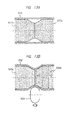
- FIGs. 12A and 12B illustrate a case as a spinning method of a conventional example in which a convex shape is formed in the radial direction of a tube material 902 by arranging a mandrel 900 having a convex shape inside the cylindrical tube material 902 and performing spinning (or one called “hera shibori” in Japanese) while pressing a roller 903 (or one called “hera” in Japanese) from outside of the tube material 902.
- a diameter "v1" of the convex portion is larger than a diameter "v2" of the other portion.
- the tube material 902' obtained subsequent to the shaping is formed into a shape transferred from the mandrel 900, and therefore, cannot be detached from the mandrel 900, or cutting of the tube material 902' obtained subsequent to the shaping or others is required.
- FIGs. 13A and 13B illustrate a case as another conventional example in which a concave shape is formed in the tube material 902 by arranging a mandrel having a concave shape formed inside the tube material 902 as an integrated object therewith and performing the spinning while pressing the roller 903 from outside of the tube material 902.
- a diameter "w1" of the concave portion is smaller than a diameter "w2" of the other portion. Therefore, also in such a method, as similar to the case of FIGs.
- the tube material 902' obtained subsequent to the shaping cannot be detached from the mandrel, and therefore, it is generally required to arrange divided mandrels 900a and 900b inside the tube material 902 as illustrated in FIGs. 13A and 13B , perform the shaping, and then, detach each of the mandrels 900a and 900b.
- a line between the mandrels 900a and 900b in FIGs. 13A and 13B represents a dividing surface between the mandrels.
- the present invention can be utilized for a technique of manufacturing a tubular component and others.
Landscapes
- Engineering & Computer Science (AREA)
- Mechanical Engineering (AREA)
- General Engineering & Computer Science (AREA)
- Shaping Metal By Deep-Drawing, Or The Like (AREA)
Abstract
Description
- The present invention relates to a spinning technique and others.
- As prior art examples, there are Japanese Patent Application Laid-Open Publication No.
S62-227520 3455892 - The Patent Document 1 ("Method of Manufacturing Twist Deformed Tube") describes "to provide a method, without using a core bar, of manufacturing a twist tapered tube or straight tube having different cross-sectional surfaces, which is formed so as to have an appearance of a twisted tube body by spirally forming a waved or polyhedral pattern on a tube outer peripheral surface in a tube longitudinal direction", and describes "a method of manufacturing a twist deformed tube, in which a hollow cylindrical tube material is rolled while holding it at both ends and applying tensile force or compressing force thereto in an axial direction of the tube material, and besides, a shaping roll is moved in the axial direction of the tube material while pressing the shaping roll against the tube material, so that the tube material is shaped into a desired shape, with using a roll whose peripheral surface is formed into a waved shape or polyhedral shape as the shaping roll".
- The Patent Document 2 ("Method of Manufacturing Step Rotating Body") describes to manufacture a step rotating body with a light weight, without distortion, with excellent concentricity, with a uniform thickness, and with good rotational balance. Also, it describes a method of manufacturing a step rotating body formed of a boss portion and a cylindrical portion which is integrally formed with the boss portion and which has a larger diameter than that of the boss portion, the method in which both ends of a thin tubular material are fitted in a cylindrical-portion die, are engaged therewith in a diameter-increasing direction, and are pressed in an axial direction to be held, a diameter of an axial-direction intermediate portion of this tubular material is decreased by a shaping roll so that the portion follows a boss-portion die provided between the above-described tubular-portion dies opposite to each other, and then, this diameter-decreased portion is cut in the middle thereof in the axial direction so as to use a part fitted in the cylindrical-portion die as the cylindrical portion and use a part fitted in the boss-portion die as the boss portion.
- The above-described
Patent Document 1 describes the method of shaping the tube material into the predetermined shape by, in spinning of the tube material which is a cylindrical raw tube, rotating the tube material supported at both ends thereof (supported by tensile force or compressing force) and moving the shaping roll (also referred to as a roller) thereon in the axial direction or longitudinal direction of the tube material while pressing the shaping roll against the tube material. In this method, the spinning is performed only with the roller without using a mandrel which is a die arranged inside the tube material or in a core in order to transfer the predetermined shape onto an outer surface of the tube material. Note that the mandrel (4) described inPatent Document 1 is described as an object for supporting the both ends of the tube material (1), and is not intended as the die which is arranged inside the above-described tube material or in the core in order to transfer the predetermined shape to the outer surface of the tube material. - However, the method as described in
Patent Document 1 has a problem of reduction in working efficiency due to long processing time because the moving direction of the roller is the axial direction or longitudinal direction of the tube material. - The above-described
Patent Document 2 describes the shaping method in the spinning of the tube material which is the cylindrical raw tube, by moving the roller in a radial direction of the tube material while pressing the roller against the axial-direction intermediate portion of the tube material. In this method, the processing or diameter-decreasing shaping is performed with taking the feeding direction of the roller as the radial direction of the tube material. However, the mandrel is introduced. - Therefore, the method as described in
Patent Document 2 has a problem of reduction in production efficiency because a step and working of detaching the tube material from the mandrel is required subsequent to the shaping. Moreover, in the case of the method using the mandrel as described above, the shape of the tube material subsequent to the shaping is largely limited. For example, the processing cannot be performed for such a shape that the diameter of the portion against which the roller is pressed to be the center portion of the tube material in the rotation-axis direction is larger than the diameter of the other portion such as the vicinity of the both ends of the tube material. This is because the tube material subsequent to the shaping cannot be detached from the mandrel or because cutting of the tube material subsequent to the shaping or others is required (seeFIG. 12 described later or others). - In consideration of the description above, a main preferred aim of the present invention for a method of spinning a tube (pipe) material is to provide a technique capable of improving working efficiency with short processing time, achieving a flexible processed shape, and improving production efficiency. More particularly, it is to provide a technique capable of achieving the above-described effects by employing a method of moving a roller in a radial direction of the tube material without using the mandrel which is a die arranged inside the tube material in order to transfer a shape.
- A typical embodiment of the present invention is a method of spinning a tube material, a machine thereof, and others, and has a feature of a configuration described below.
- The spinning method according to the present embodiment uses components including: a tube material; a pair of chucks which hold and rotate both ends of the tube material; and a roller which is a rotating symmetrical body having a predetermined curved shape on a side surface thereof in order to shape the tube material. A mandrel or others is not arranged inside the tube material. The present method provides a state that circumferential portions at the both ends of the tube material are fitted in and held by circumferential grooves provided on respective side surfaces of a pair of chucks facing each other. In the present method, the chucks holding the tube material are rotated around a first axis, and the roller is rotated around a second axis. The rotating axial directions of the first axis and the second axis are the same as each other as a first direction, and the radial direction thereof is a second direction. The present method includes a step of moving the rotating roller in the second direction and pressing a side surface of the roller against a side surface of the rotating tube material between the rotating chucks from outside, so that a curved shape of the side surface of the roller is transferred to the side surface of the tube material.
- Moreover, in the present method, for example, in the first direction, when a width of the side surface of the roller is assumed as "P1" and a distance between the side surfaces of the pair of chucks facing each other where the side surface of the tube material exists is assumed as "Q1", a value of "P1/Q1" that is a ratio between them is larger than 0.9 but smaller than 1.0.
- Moreover, in the present method, for example, a shape of the side surface of the roller is a concave curved shape which is concave in the second direction at a center thereof in the first direction, and a shape of the tube material or a tubular shaped component obtained subsequent to the shaping is formed into a portion having a convex curved shape which is convex in the second direction.
- Moreover, in the present method, for example, each width of the grooves provided on the side surfaces of the chucks is designed to have a length obtained by addition of a thickness of an end portion of the tube material and a processing tolerance, and the processing tolerance is designed in consideration of margin upon fitting the end portion of the tube material into the grooves of the chucks and consideration of holding force upon the rotation.
- According to the typical embodiment of the present invention, for the method of spinning the tube material, the working efficiency can be improved with short processing time, the flexible processed shape can be achieved, and the production efficiency can be improved.
- More particularly, the working and processing time is shortened by taking the moving direction of the roller as the radial direction of the raw tube, so that the working efficiency can be improved. Moreover, the spinning without using the mandrel can be achieved, and the detachment from the mandrel or others is unnecessary, so that the production efficiency can be improved. Further, the present invention can achieve the processing or the shaping of the flexible shape including, for example, a shape of a tube material having a larger diameter at a center portion in a rotation-axis direction than those at both sides thereof in accordance with the shape of the roller, and besides, a thickness of the material obtained subsequent to the processing or the shaping is prevented from being decreased or is increased.
- In the drawings:
-
FIG. 1 is a perspective view illustrating a configuration of a tube material, chucks, and a roller in a spinning method and machine according to an embodiment of the present invention; -
FIG. 2 is a diagram illustrating an entire configuration of the spinning machine according to the embodiment of the present invention; -
FIG. 3A is a cross-sectional view illustrating an outline of a processing state in the spinning method and machine according to the embodiment of the present invention, the processing state being prior to the processing; -
FIG. 3B is a cross-sectional view illustrating an outline of a processing state in the spinning method and machine according to the embodiment of the present invention, the processing state being subsequent to the processing; -
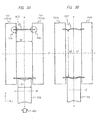
FIG. 4A is a cross-sectional view illustrating a configuration of chucks which are a tube-end holding tool, which illustrates a Z-X cross-sectional surface of the chuck; -
FIG. 4B is a cross-sectional view illustrating the configuration of the chuck which is the tube-end holding tool, which illustrates an enlarged state of a groove; -
FIG. 4C is a cross-sectional view illustrating the configuration of the chuck which is the tube-end holding tool, which illustrates a state that an end of the tube material is held by the groove; -
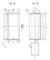
FIG. 5A is a perspective view illustrating a configuration of a tube material, which is a view illustrating the tube material whose circumference is continued; -
FIG. 5B is a perspective view illustrating a configuration of a tube material, which is a view illustrating the tube material whose circumference is not continued; -
FIG. 6A is a plan view illustrating a shape of the tube material, which illustrates a Z-X plane surface prior to shaping; -
FIG. 6B is a plan view illustrating the shape of the tube material, which illustrates the Z-X plane surface subsequent to the shaping and a roller; -
FIG. 7 is a plan view illustrating a shape of the roller; -
FIG. 8 is a cross-sectional view illustrating a rotational configuration of the tube material and the roller at a line a-a ofFIG. 3 ; -
FIG. 9 is a diagram of summarized results of a relation of influence on corrugation occurrence and shaping availability due to a ratio (P1/Q1) of a roller width and a distance between chucks in the present spinning method; -
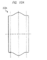
FIG. 10A is a diagram illustrating a shape of a roller of a modification example in the present embodiment; -
FIG. 10B is a diagram illustrating a shape of a roller of a modification example in the present embodiment; -
FIG. 10C is a diagram illustrating a shape of a roller of a modification example in the present embodiment; -
FIG. 10D is a diagram illustrating a shape example of a processed product in the present embodiment; -
FIG. 10E is a diagram illustrating a shape of a roller of a modification example in the present embodiment; -
FIG. 10F is a diagram illustrating a shape example of a processed product in the present embodiment; -
FIG. 11A is a cross-sectional view illustrating a processing state in a pressing method of a conventional technique example, the processing state being prior to processing, -
FIG. 11B is a cross-sectional view illustrating a processing state in the pressing method of the conventional technique example, the processing state being subsequent to the processing, -
FIG. 11C is a cross-sectional view illustrating a processing state in a pressing method of a conventional technique example, which illustrates a plate material subsequent to the processing; -
FIG. 12A is a cross-sectional view illustrating an outline of a first example of a spinning method with using a mandrel; -
FIG. 12B is another cross-sectional view illustrating the outline of the first example of the spinning method with using the mandrel; -
FIG. 13A is a cross-sectional view illustrating an outline of a second example of a spinning method with using a mandrel; and -
FIG. 13B is another cross-sectional view illustrating the outline of the second example of the spinning method with using the mandrel. - Hereinafter, a spinning method, a spinning machine, and others according to an embodiment of the present invention will be described in detail based on the drawings. Note that the same components are denoted by the same reference symbol in principle throughout all the drawings for describing the embodiment, and the repetitive description thereof will be omitted.
-
FIG. 1 illustrates a configuration of atube material 102, chucks 101 which are a tube-end holding tool, and aroller 103 in a spinning method and machine according to the present embodiment. As direction in explanation, "Z" is a rotation-axis direction, and "X" and "Y" are radial directions as illustrated in the drawing. - The
tube material 102 is a raw tube in other words, such as a hollow cylindrical metal material as also illustrated inFIG. 5 and others. The circumferences at both ends of thetube material 102 is held or restricted by grooves 104 (FIG. 4 ) ofchucks 101. - The pair of tube-
end holding tools 101 are chucks for holding or restricting the circumferences at the both ends of thetube material 102, and are made of, for example, columnar or disk-shaped metal. The tube-end holding tools 101 include aportion 101a on one side and aportion 101b on the other side which have similar configurations to each other, which are provided with therespective grooves 104 for entirely holding or restricting the circumferences at the ends of thetube material 102 as described later (FIG. 4 ). Theraw tube 102 is arranged between the pair of chucks 101 (101a and 101b), and the ends thereof are fitted in thegrooves 104. - The
roller 103 is a shaping roller in other words, and is roughly a columnar rotating symmetrical body, and more specifically has a concave shape as a curved surface of a side surface thereof as illustrated inFIGs. 3 ,7 , and others. - The
tube material 102 and thechucks 101 are rotated around an axis J1. Theroller 103 is rotated around an axis J2. Also, theroller 103 is moved in the radial direction (X) of thetube material 102 as illustrated by anarrow 401. -
FIG. 2 illustrates an overall configuration of the spinningmachine 10 which is a system of the present embodiment in accordance with the spinning method of the present embodiment. As described in detail later, thepresent spinning machine 10 performs spinning of thetube material 102, drive control of the spinning, and others. Thepresent spinning machine 10 is configured to include: a controllingunit 11; aroller driving unit 12; arotation driving unit 13; an axial-movement driving unit 14; rotatingchucks roller rotating chuck 202; and others, in which thechucks 101 and theraw tube 102 ofFIG. 1 are set between therotating chucks roller 103 is set at theroller rotating chuck 202. For example, ashaft 202c of theroller rotating chuck 202 is detachable, and theroller 103 whose type depends on a desired shape in the shaping is attachable and detachable. - In the configuration example of
FIG. 2 , therotating chuck 201b is configured to be movable in the axial (Z) direction. In this manner, thechucks 101 and thetube material 102 are attachable and detachable between therotating chucks chuck 101a is fixed to onerotating chuck 201a, and theother chuck 101b is fixed to the otherrotating chuck 201b. By therotating chuck 201a and therotation driving unit 13, the rotation of the chucks 101 (101a and 101b) and thetube material 102 around the axis J1 is driven. - Also, by the
roller driving unit 12 and theroller rotating chuck 202, rotation of theroller 103 around the axis J2 and movement thereof are driven. The movement of theroller 103 includes at least movement in the X direction, and is further configured that it is freely movable in the X, Y, and Z directions, so that more complex processing can be performed. - Upon the processing, the
roller 103 is moved in the radial (X) direction of theraw tube 102 as illustrated by thearrow 401 together with the rotation of theroller 103, and is caused to approach to and is pressed against an outer surface of the side surface of theraw tube 102 provided between thechucks FIG. 3B , a desired shape is formed by transferring the concave shape which is the shape of the side surface of theroller 103 onto the outer surface of the side surface of theraw tube 102. - The controlling
unit 11 provides a control command to theroller driving unit 12, therotation driving unit 13, the axial-movement driving unit 14, or others so as to control their driving. Note that the controllingunit 11 can be configured by a publicly-known technique such as an IC chip or a calculator, and each of the driving units (12, 13, and 14) can be configured by a publicly-known technique such as a motor or others. Each of the rotating chucks (201a, 201b, and 202) can be also configured by a publicly-known technique. -
FIGs. 3A and 3B illustrate outlines of the spinning method of the present embodiment in cross-sectional views.FIG. 3A illustrates thechucks 101, thetube material 102, and theroller 103 in a state prior to the processing, and particularly illustrates a state in which theroller 103 is in contact with thetube material 102.FIG. 3B illustrates a shape/a state of a tube material 102' obtained subsequent to the processing in which theroller 103 has been moved in the radial (X) direction of thetube material 102 and been pushed in. - In
FIG. 3A , theraw tube 102 is arranged between the tube-end holding tools 101 (101a and 101b) which are the pair of chucks arranged so as to face each other, and the circumferences at the both ends of theraw tube 102 are entirely fitted in the grooves 104 (FIG. 4 ) of therespective chucks 101 and are held or restricted by them. - The
roller 103 is arranged at a position outside theraw tube 102 on a line a-a between thechucks tube material 102 and theroller 103 in Z direction. A symbol "P1" represents a width or a length of theroller 103 in the axial (Z) direction. A symbol "Q1" represents a distance between surfaces of thechucks roller 103 can be pressed. - In the present method, spinning which shapes the
tube material 102 into a desired shape can be performed so as to change fromFIG. 3A to FIG. 3B by moving or feeding theroller 103 in the radial (X) direction of thetube material 102 as illustrated by thearrow 401 together with the rotation drive of thechucks 101, thetube material 102, and theroller 103 and pressing it. - In
FIG. 3B , theroller 103 is moved to a predetermined position in the X direction and is pressed against the side surface of the tube material 102', so that the concave shape which is the shape of the side surface of theroller 103 is transferred onto the side surface of the tube material 102'. The shape of the tube material 102' subsequent to the shaping is a rotating symmetrical body around the axis J1. Note that a symbol "k1" represents an inner diameter of the convex portion of the tube material 102' and a symbol "k2" represents an inner diameter of the concave portion thereof obtained subsequent to the processing. In this manner, in the present method, the spinning of thetube material 102, that is, the transferring of the desired shape thereto can be performed without the usage of the mandrel which is the die arranged inside thetube material 102 and without the movement of theroller 103 in the axial (Z) direction of thetube material 102. Moreover, as illustrated in the drawings, the processing can be performed so as to form an outward-convex shape in the vicinity of the line a-a which is the center of the tube material 102' in the axial (Z) direction. -
FIG. 4A illustrates a cross-sectional surface of thechuck 101a in a Z-X plane (note that thechuck 101b is also similar), andFIG. 4B illustrates theenlarged grooves 104.FIG. 4C illustrates a state in which anend 406 of thetube material 102 is fitted in and held by thegrooves 104. Thecircumferential groove 104 is provided on one side surface of thechuck 101a. Thegroove 104 can be provided by, for example, grooving a surface of a metal disk by cutting or others. - The
groove 104 is designed so as to have dimensions, positions, and shapes, which are equal to those of the outer diameter (S1) and the inner diameter (S2) of the raw tube 102 (FIGs. 5 and6 ). Note that this designing includes the design of the processing tolerance. A diameter of anouter circumference surface 404 of thegroove 104 is equal to S1, a diameter of aninner circumference surface 405 thereof is equal to S2, and a width "h2" of thegroove 104 and a thickness "g1" of thetube material 102 are equal to each other (h2 ≅ g1). Note that such designing that the width h2 and the thickness g1 are equal to each other (h2 ≅ g1) includes the processing tolerance. Also, a depth "h1" of thegroove 104 is designed so as to match with a length "h1" (FIG. 6 A) of theend 406 of thetube material 102 to be held or fitted therein. - Further, a rounded or tapered portion or others is provided to
ends groove 104 on the side surface of thechuck 101 so that the corner portions are smoothed (beveled). Correspondingly, a rounded or tapered portion or others is similarly provided to the both ends 406 which are the circumferences of the tube material 102 (FIG. 5 ) so that they are smoothed (beveled). In this manner, damage of contact surfaces at these portions (402, 403, and 406) can be protected upon the fitting and holding of the end of thetube material 102 by thegrooves 104 of thechuck 101, upon the detachment of thetube material 102 from thechuck 101 subsequent to the shaping, and upon the processing in the holding state. Moreover, by smoothing the corner portions as described above, the working of the fitting and the detachment can be easily performed, and besides, the shaping availability is enhanced. - Also, as the working prior to the processing, the end of the
tube material 102 is fitted in and held or restricted by thegrooves 104 of thechucks 101. In order to easily perform this working and sufficiently continuously hold thetube material 102 by thechucks 101 upon the processing together with the rotation, the width h2 of thegroove 104 and the depth h1 thereof matching with the thickness g1 of thetube material 102 are designed so as to include the processing tolerances. That is, while the relation "h2 ≅ g1" is roughly employed, the tolerance is designed so as to have a relation "h2 = g1 + x" in, for example, consideration of a margin "x" in order to easily perform the fitting of theend 406 into thegroove 104, and consideration of the holding or restricting force that prevents thetube material 102 from sliding with respect to thechucks 101 upon the rotation of thechucks 101 and thetube material 102 due to the rotation of therotating chuck 201a. For example, the tolerance is 10% or less (0.1 mm or less) with respect to aplate thickness 1 mm. - Note that, as another means or modification example for protecting or holding the contact surface of the
groove 104 with the end of thetube material 102, a method of sandwiching or interposing a predetermined protecting member or liquid agent between thegroove 104 and theend 406 of thetube material 102 may be employed. In this case, the width h2 of thegroove 104 or others is designed in consideration of a sandwiched amount. Also, in a case that the protection of theend 406 of thetube material 102 is not required, it is not required to provide the above-described protecting means. - The present method has a configuration that the both ends of the
tube material 102 are held by thecircumferential grooves 104 in order to hold thetube material 102 by thechucks 101 without using the mandrel, and this configuration does not require the tensile force, the compressing force, or others in the axial direction for holding the both ends of the tube material as different fromPatent Document 1 which is a conventional technique example. -
FIGs. 5A ,5B ,6A, and 6B illustrate configurations of thetube material 102 which is the raw tube.FIGs. 5A and5B illustrate perspective configurations of theraw tube 102 obtained prior to the processing,FIG. 6A illustrates a Z-X plane obtained prior to the processing, andFIG. 6B illustrates a Z-X plane of the tube material 102' and theroller 103 obtained subsequent to the processing. - In
FIGs. 5A ,5B , and6A , the cylindricalraw tube 102 is manufactured or prepared by, for example, a publicly-known method such as roll bending, pushing-in, or roll shaping.FIGs. 3 and4 and others illustrate a state that the ends 406 of theraw tube 102 are fitted in thegrooves 104 and are left as they are. Therefore, the tubularraw tube 102 illustrated inFIG. 5A whose circumference is continued by welding or others and the tubularraw tube 102 illustrated inFIG. 5B whose circumference is not continued can be used. - The
raw tube 102 illustrated inFIG. 5B has aregion 409 whose circumference is not continued at a part of the circumference and which extends lengthwise in the width (Z) direction. In thisregion 409, anupper portion 407 and alower portion 408 in the circumferential (X) direction are separated from each other. - The symbol S1 of
FIG. 5A is the outer diameter which is the diameter in the radial (X) direction, and the symbol S2 is the inner diameter. At the both ends 406 on the circumferential of theraw tube 102, the portions illustrated as the widths h1 ofFIG. 6A are fitted in the above-describedgrooves 104, and a length Q1 obtained by subtracting the width portions h1 at the both ends from a total length Q2 in the axial (Z) direction is a distance between the above-described chucks 101 (FIG. 3 ). - One of characteristics of the present method is to perform the spinning without using the mandrel. Therefore, as described above, the
grooves 104 which are designed in accordance with the dimensions equal to the outer diameter S1 of theraw tube 102 and the inner diameter S2 thereof are provided on thechucks 101, and the both ends 406 of theraw tube 102 are fitted in thegrooves 104 without a space therebetween. In this manner, this is a method in which the ends of theraw tube 102 are held or fixed by thegrooves 104 with a sufficient force so that theraw tube 102 is rotated together with the rotation of thechuck 101, and therefore, the detachment of theraw tube 102 or the spinning around of only thechucks 101 because of the rotation does not occur. - In
FIG. 6B , as a shape of the tube material 102' obtained subsequent to the shaping by theroller 103 as described above inFIG. 3B , a symbol "K1" represents an outer diameter which is a diameter of thetube material 102 at a most convex portion which is at an intermediate position "M1" in the axial (Z) direction corresponding to the line a-a. A symbol "K2" is an outer diameter which is a diameter of thetube material 102 at most concave portions which are positions "M2" on both sides of the position M1 with the outer diameter K1 in the vicinities of both ends in the axial (Z) direction. The symbols M1 and K1 correspond to a position "L1" of a most concave portion in the shape of theroller 103 inFIG. 7 , and the symbols M2 and K2 correspond to positions "L2" of most convex portions thereof. The symbols k1 and k2 inFIG. 3B described above represent the inner diameters corresponding to the symbols K1 and K2. - A limitation of a formed shape is large in a case of a spinning method in a conventional method in which the mandrel is arranged inside the raw tube so that the shape of the mandrel and the shape of the roller are transferred to the raw tube between the mandrel and the roller (supplementation in
FIGs. 12 and13 described later) . On the other hand, the method of the present embodiment has such a developed configuration that the spinning without using the mandrel inside theraw tube 102 can be performed, and therefore, it is possible to form such a convex shape that the diameter K1 in the vicinity of the center of theraw tube 102 in the axial (Z) direction is larger than the diameter K2 on the both sides thereof in accordance with the concave shape of theroller 103. Similarly, for example, in a case that theroller 103 has a convex shape (FIG. 10A described later), it is also possible to form such a concave shape that the diameter K1 in the vicinity of the center of theraw tube 102 in the axial (Z) direction is smaller than the diameter K2 on the both ends thereof. - Moreover, in the case of the present method, an effect that a thickness g1' of the tube material 102' obtained subsequent to the shaping at the position M1 on the line a-a is slightly larger than the original thickness g1 in accordance with the shape of the
roller 103 is obtained. Although the thickness obtained subsequent to the shaping is decreased in the conventional pressing method (FIG. 11 ) and the method with using the mandrel inside the tube material, the thickness in the present method is not decreased. -
FIG. 7 illustrates the shape of theroller 103 and the cross-sectional surface thereof on a Z-X plane. A symbol "P1" represents a width or a length of theroller 103 in the axial (Z) direction, a symbol "R1" represents a diameter or a length thereof in the radial (X) direction which is the diameter at the position L1 of the most concave portion at the center in the axial (Z) direction corresponding to the line a-a, and a symbol "R2" represents a diameter at the positions L2 of the most convex portions in the vicinities of the both ends in the axial (Z) direction. A symbol "R3" represents a height or a depth of the concave/convex. The concave shape at the position L1 is transferred to the position M1 of the above-described tube material 102 (FIG. 6 ) to be the convex shape at the position M1, and the convex shape at the position L2 is transferred to the position M2 of thetube material 102 to be the concave shape at the position M2. - As the shape of the
roller 103, the concave, convex, and others based on the diameters (R1 and R2) at the respective positions (L1 and L2) are designed. More particularly, a more complex shape can be also formed by using aroller 103 designed to have a shape having different curvature factors (c1 and c2) from each other at the respective positions (L1 and L2). -
FIG. 8 illustrates a configuration of the rotation of thetube material 102 and theroller 103 on the cross-sectional surface taken along the line a-a ofFIG. 3 . Thechucks 101 and thetube material 102 are rotated around the axis J1, and theroller 103 is rotated around the axis J2. Theroller 103 positioned outside the rotatingraw tube 102 is moved in the radial (X) direction of theraw tube 102 as illustrated by the arrow of 401 while rotating, and the concave/convex shape of the above-described roller 103 (FIG. 7 ) is transferred to the side-surface portion of theraw tube 102, so that the shaping can be performed. - Note that the
chucks 101 are not limited to have the column or disk shape, but can have a hollow cylindrical or ring shape or others. - Note that one
roller 103 having a predetermined shape is described in the present embodiment. However, the number of rollers is not limited to this, and a plurality ofrollers 103 may be used in combination. For example, a plurality ofrollers 103 having the same shape may be prepared, and theserollers 103 may be pressed at the same time from respective directions in periphery of thetube material 102. Also, a plurality of types ofrollers 103 designed to have different shapes from each other may be prepared and be used separately in accordance with a shape of the tube material 102' or a product to be targeted. A modification example of the shape of theroller 103 will be described later (FIG. 10 ). -
FIG. 9 illustrates results of influence on corrugation occurrence and shaping availability due to a ratio (P1/Q1) of a width P1 of theroller 103 and a distance Q1 between thechucks 101 described above (inFIG. 3 ) in the present spinning method and machine, the results being studied by finite element analysis. Depending on the value of P1/Q1 which is the ratio of the width P1 of theroller 103 with respect to the length Q1 between the chucks 101 (101a and 101b), for example, presence/absence of the occurrence of the corrugation such as undesired concave/convex is affected. - As a result of the study, when the value of P1/Q1 is smaller than 0.9 such as 0.6 or 0.8, the corrugation occurs on the processed surface of the
tube material 102, and the shape of theroller 103 cannot be correctly or accurately transferred to theraw tube 102, and therefore, effective shaping cannot be performed. When the value of P1/Q1 is in a range larger than 0.9 but smaller than 1.0 such as 0.9 or 0.95, the corrugation does not occur on the processed surface, and the shape of theroller 103 can be correctly or accurately transferred to theraw tube 102, and therefore, the effective shaping can be achieved. In consideration of the above-described results, a design mode of a dimension, a shape, and others of each portion is preferably made so that the value of P1/Q1 is in the range larger than 0.9 but smaller than 1.0. - An example of a working procedure upon the processing in the present spinning method and machine (
FIG. 2 ) will be described as follows. - (1) As illustrated in
FIG. 2 , thechucks 101 and thetube material 102 are attached to the rotatingchucks chuck 101a is attached to therotating chuck 201a, and theend 406 of thetube material 102 is attached to thegroove 104 of thechuck 101a as illustrated inFIG. 1 . Also, theother chuck 101b is attached to the otherrotating chuck 201b. Therotating chuck 201b is driven by the axial-movement driving unit 14 so as to move in the axial (Z) direction, so that thegroove 104 of thechuck 101b and theother end 406 of thetube material 102 are connected to each other. In this manner, as illustrated inFIG. 3A , thetube material 102 is set or fitted in thegrooves 104 of thechucks 101, and thetube material 102 is held or restricted. - (2) The
roller 103 whose type corresponds to a desired shape is attached to theroller rotating chuck 202. They are arranged so that the centers of theraw tube 102 and theroller 103 in the axial (Z) direction are on the line a-a. - (3) By processing start by an operation of an operator, a NC program input, or others, a control command is issued from the controlling
unit 11 to each of the units (12, 13, and 14). Theroller rotating chuck 202 is driven by theroller driving unit 12 so as to rotate theroller 103. Therotating chuck 201a is driven by therotation driving unit 13 so as to rotate thechucks 101 and thetube material 102. - (4) The
roller rotating chuck 202 is driven by theroller driving unit 12 so as to move or feed theroller 103 in the X direction, press theroller 103 against the outer side surface of theraw tube 102 as illustrated inFIG. 3A , and push the roller to a predetermined position as illustrated inFIG. 3B , so that theraw tube 102 is shaped into a desired shape. - (5) Subsequent to the shaping of the above-described desired shape, the
roller 103 is returned to an original position, the rotation of each unit is stopped, and the tube material 102' obtained subsequent to the processing is detached from the present machine. -
FIGs. 10A and10B illustrate modification examples of theroller 103. Aroller 103a ofFIG. 10A is a case having a convex shape. The tube material 102' can be shaped into a concave shape by theroller 103a ofFIG. 10A . Theroller 103b ofFIG. 10B is a case having two concave shapes parallely provided in the axial (Z) direction which are a wave shape having a convex shape at a center. The tube material 102' can be shaped into two parallely convex shapes by theroller 103b ofFIG. 10B . -
FIG. 10C illustrate a shape of another modification example of theroller 103.FIG. 10D illustrates a shape example of theraw tube 102 which is a processed product by theroller 103 ofFIG. 10C .FIG. 10E illustrate a shape of still another modification example of theroller 103.FIG. 10F illustrates a shape example of theraw tube 102 which is a processed product by theroller 103 ofFIG. 10E . - The
roller 103 usable in the present embodiment is not limited to have the symmetrical shape whose right and left shapes are the same as each other with respect to the line a-a serving as the center position in the axial (Z) direction as illustrated in above-describedFIG. 3 , but can be an asymmetrical shape whose right and left shapes are different from each other with respect to the line a-a. - For example, the
roller 103 illustrated inFIG. 10C has the asymmetrical shape whose right and left shapes are different from each other with respect to the line a-a. A diameter thereof at a position "D5" in the axial (Z) direction corresponding to the line a-a is denoted by a symbol "B4". In the right-side shape thereof with respect to the line a-a, a diameter at a position "D1" in the axial (Z) direction is denoted by a symbol "B3". Also, a diameter at a position "D2" in the axial (Z) direction which is a right-side end is denoted by a symbol "B2". In the left-side shape thereof with respect to the line a-a, a diameter at a position "D3" in the axial (Z) direction is denoted by a symbol "B1". Also, a diameter at a position "D4" in the axial (Z) direction which is a left-side end is also denoted by a symbol "B1". The diameter B2 is smaller than the diameter B1 and the diameter B3. The diameter B4 is smaller than the diameter B1. - Each of symbols "C1", "C2" , and "C3" represents a width from/to or a distance between the above-described portions in the Z direction. The symbol C1 represents the width or distance from the position D4 which is one end to the position D2 which is the other end. The symbol C2 represents the width or distance from the position D4 to the position D3. The symbol C3 represents the width or distance from the position D1 to the position D2.
- The positions D1, D2, D3, and D4 in the
roller 103 ofFIG. 10C are transferred correspondingly to positions "D11", "D21", "D31", and "D41" in side-surface portions of theraw tube 102 ofFIG. 10D . In this manner, theraw tube 102 ofFIG. 10D can be shaped into a shape whose right and left shapes are asymmetric with respect to a position "C21". Note that symbols "C1'", "C2'", and "C3'" ofFIG. 10D represent widths or distances obtained subsequent to the shaping, corresponding to the symbols C1, C2, and C3 ofFIG. 10C . - Also, the
roller 103 having the shape illustrated inFIG. 10E can form a linear portion illustrated by a symbol C2' in the axial (Z) direction of theraw tube 102 ofFIG. 10F . Theroller 103 ofFIG. 10E has a tapered portion having a tapered shape in which the width B1 is decreased to the width B5 from the position D3' to the position D4' in the portion C2 in the axial (Z) direction. In the portion C2, theroller 103 ofFIG. 10E has a tapered portion having a tapered shape in which a diameter of the width B5 serving as a narrow portion corresponding to the position D4' is smaller than a diameter of the width B1 serving as a wide portion corresponding to the position D3'. A difference between the width B1 and the width B5 is a width "B6". - By providing the above-described tapered portion in the
roller 103, theraw tube 102 is swelled when theraw tube 102 is processed by theroller 103, so that the straight portion denoted by C2' inFIG. 10F is formed. In the linear portion denoted by C2', the diameters in the X direction are equal to each other. - When the linear portion denoted by C2' is formed in the
raw tube 102 ofFIG. 10F , in the width of the portion C2 of theroller 103 ofFIG. 10E in the axial (Z) direction with respect to C1 which is the total length of theroller 103 in the axial (Z) direction, it is desired that a ratio "C2/C1" of C1 occupied by C2 is larger than 0.04 but smaller than 0.2. In this manner, the linear portion denoted by C2' ofFIG. 10F is successfully formed. - Also, the tapered shape of the tapered portion of the above-described
roller 103 which is particularly preferred to the above-described successful formation of the linear portion is a shape having a ratio "B1/B5" which is a ratio of the widths in the X direction, that is, a ratio of the wide portion and the narrow portion is larger than 1 but smaller than 1.03. - As explained above, the spinning method of the present embodiment is a transferring method by moving the
roller 103 having the predetermined shape in the radial (X) direction of thetube material 102 while pressing against thetube material 102 without the mandrel by holding the both ends of thetube material 102 by thegrooves 104 of the pair ofchucks 101. The spinning can be performed without using the mandrel, and therefore, a step and a working of mounting the mandrel or others to be performed prior/subsequent to the processing are eliminated, so that workability and working efficiency are improved. Also, by taking the moving direction of theroller 103 as the radial (X) direction of theraw tube 102, the processing time can be shortened, and the production efficiency can be improved. Further, in accordance with the shape of theroller 103, such a flexible formed shape as the concave shape or the convex shape in the vicinity of the center of thetube material 102 in the axial (Z) direction can be achieved, so that a degree of freedom is high. - In comparison with a conventional method, for example, when a complex shape is processed by a pressing method as illustrated in
FIGs. 11A to 11C , a thickness thereof obtained subsequent to the processing is decreased.FIG. 11A is a cross-sectional surface obtained prior to the pressing, andFIG. 11B is a cross-sectional surface obtained subsequent to the pressing. Asymbol 301 represents a press die which is a base having a concave portion, asymbol 302 represents a plate material which is a processing target and a material prior to the processing, and asymbol 303 represents a press punch having a convex shape.FIG. 11C is a cross-sectional surface of a plate material 302' obtained subsequent to the pressing ofFIG. 11B . More particularly, inFIGs. 11B and 11C , the thickness of the plate material 302' obtained subsequent to the processing is largely decreased in a portion having such a large deformation amount as a plate thickness obtained subsequent to the press shaping which is a thickness portion denoted by asymbol 411 on a line b-b. On the other hand, the method of the present embodiment is a method in which the deformation is performed in the radial direction of theraw tube 102 without using the mandrel, and besides, in which the both ends 406 of the tube material are restricted, and therefore, the tube material is deformed so as not to stretch in the Z direction ofFIG. 6 which is the longitudinal direction but to shrink in the radial direction, and the deformed portion is shifted in the plate thickness direction, so that the above-described thickness g1 is prevented from being decreased or is increased. - As a supplement,
FIGs. 12A and 12B illustrate a case as a spinning method of a conventional example in which a convex shape is formed in the radial direction of atube material 902 by arranging amandrel 900 having a convex shape inside thecylindrical tube material 902 and performing spinning (or one called "hera shibori" in Japanese) while pressing a roller 903 (or one called "hera" in Japanese) from outside of thetube material 902. A diameter "v1" of the convex portion is larger than a diameter "v2" of the other portion. In consideration of such a method, the tube material 902' obtained subsequent to the shaping is formed into a shape transferred from themandrel 900, and therefore, cannot be detached from themandrel 900, or cutting of the tube material 902' obtained subsequent to the shaping or others is required. - Similarly,
FIGs. 13A and 13B illustrate a case as another conventional example in which a concave shape is formed in thetube material 902 by arranging a mandrel having a concave shape formed inside thetube material 902 as an integrated object therewith and performing the spinning while pressing theroller 903 from outside of thetube material 902. In this case, a diameter "w1" of the concave portion is smaller than a diameter "w2" of the other portion. Therefore, also in such a method, as similar to the case ofFIGs. 12A and 12B , the tube material 902' obtained subsequent to the shaping cannot be detached from the mandrel, and therefore, it is generally required to arrange dividedmandrels tube material 902 as illustrated inFIGs. 13A and 13B , perform the shaping, and then, detach each of themandrels mandrels FIGs. 13A and 13B represents a dividing surface between the mandrels. - In consideration of the methods as the above-described examples in order to form a tubular component having a convex shape or a concave shape in a radial direction or continuously forming convex shapes and concave shapes, it is difficult to detach the mandrel inside the tube material, or it is required to perform the processing partially and separately. In other words, the efficiency is bad because the formation cannot be collectively performed at once or because of others, and the limitation of the formed shape is large.
- In the foregoing, the invention made by the inventors has been concretely described based on the embodiments. However, it is needless to say that the present invention is not limited to the foregoing embodiments and various modifications and alterations can be made within the scope of the present invention.
- The present invention can be utilized for a technique of manufacturing a tubular component and others.
Claims (14)
- A spinning method using elements including: a tube material; a pair of chucks which hold and rotate both ends of the tube material; and a roller which is a rotating symmetrical body having a predetermined curved shape on a side surface thereof in order to shape the tube material,
in a state that circumferential portions at the both ends of the tube material are fitted in and held by circumferential grooves provided on side surfaces of the pair of chucks facing each other, respectively,
when the chucks holding the tube material are rotated around a first axis, the roller is rotated around a second axis, axial directions of the rotation around the first axis and the rotation around the second axis are the same as each other in a first direction, and a radial direction the rotation is a second direction,
the method comprising a step of transferring a curved shape of a side surface of the roller to a side surface of the tube material by moving the rotating roller in the second direction and pressing, from outside, the side surface of the roller against the side surface of the rotating tube material between the rotating chucks. - The spinning method according to claim 1,
wherein, in the first direction, when a width of the side surface of the roller is denoted by P1 and a distance between the side surfaces of the pair of chucks facing each other where the side surface of the tube material exists is denoted by Q1, a value of P1/Q1 which is a ratio between them is larger than 0.9 but smaller than 1.0. - The spinning method according to claim 1,
wherein a shape of the side surface of the roller is a curved shape which is concaved in the second direction at a center in the first direction, and,
as a shape of the tube material obtained subsequent to the shaping, a portion having a curved shape which is convex in the second direction is shaped. - The spinning method according to claim 1,
wherein a shape of the side surface of the roller is a curved shape which is convex in the second direction at a center in the first direction, and,
as a shape of the tube material obtained subsequent to the shaping, a portion having a curved shape which is concaved in the second direction is shaped. - The spinning method according to claim 1,
wherein each width of the grooves provided on the side surfaces of the chucks is designed so as to have a length obtained by addition of a thickness of the end of the tube material and a processing tolerance, and
the processing tolerance is designed in consideration of a margin upon fitting of the end of the tube material into the grooves of the chucks and consideration of a holding force upon the rotation. - A spinning machine comprising:a tube material;a pair of chucks which hold and rotate both ends of the tube material;a roller which is a rotating symmetrical body having a predetermined curved shape on a side surface thereof in order to shape the tube material;a first driving unit which rotates the pair of chucks;a second driving unit which rotates and moves the roller; anda controlling unit which controls the first driving unit and the second driving unit,the machine being configured to fit and hold circumferential portions at the both ends of the tube material into and by circumferential grooves provided on side surfaces of the pair of chucks facing each other, respectively, and,when the chucks holding the tube material are rotated around a first axis, the roller is rotated around a second axis, axial directions of the rotation around the first axis and the rotation around the second axis are the same as each other in a first direction, and a radial direction of the rotation is a second direction,a curved shape of a side surface of the roller being transferred to a side surface of the tube material by moving the rotating roller in the second direction and pressing, from outside, the side surface of the roller against the side surface of the rotating tube material between the rotating chucks.
- The spinning machine according to claim 6,
wherein, in the first direction, when a width of the side surface of the roller is denoted by P1 and a distance between the side surfaces of the pair of chucks facing each other where the side surface of the tube material exists is denoted by Q1, a value of P1/Q1 which is a ratio between them is larger than 0.9 but smaller than 1.0. - The spinning machine according to claim 6,
wherein a shape of the side surface of the roller is a curved shape which is concaved in the second direction at a center in the first direction, and,
as a shape of the tube material obtained subsequent to the shaping, a portion having a curved shape which is convex in the second direction is shaped. - The spinning machine according to claim 6,
wherein a shape of the side surface of the roller is a curved shape which is convex in the second direction at a center in the first direction, and,
as a shape of the tube material obtained subsequent to the shaping, a portion having a curved shape which is concaved in the second direction is shaped. - The spinning machine according to claim 6,
wherein a shape of the side surface of the roller is asymmetric with respect to a center in the first direction or a first position so that a shape and a diameter of the roller on a left side and a shape and a diameter of the roller on a right side are different from each other, and,
as a shape of the tube material obtained subsequent to the shaping, with respect to the center in the first direction or the first position, the shape of the roller on the left side is transferred to a left side of the tube material, and the shape of the roller on the right side is transferred to a right side of the tube material, so that the shape of the tube material on the left side and the shape thereof on the right side are different from each other. - The spinning machine according to claim 6,
wherein the roller has a tapered portion having a tapered shape,
the tapered shape of the tapered portion is a shape having a ratio of a wide portion and a narrow portion in the second direction which is larger than 1.00 but smaller than 1.03, and is a shape having a ratio of the tapered portion occupying a total length of the roller in the first direction which is larger than 0.04 but smaller than 0.2, and,
as the shape of the tube material obtained subsequent to the shaping, a linear portion in the first direction is shaped in the tube material by the tapered portion of the roller. - The spinning machine according to claim 6,
wherein the tube material is a tube material whose circumference is continued or a tube material whose circumference is not continued and is divided in the second direction into an upper portion and a lower portion in a region extending in the first direction in which the circumference is not continued. - The spinning machine according to claim 6,
wherein each width of the grooves provided on the side surfaces of the chucks is designed so as to have a length obtained by addition of a thickness of the end of the tube material and a processing tolerance, and
the processing tolerance is designed in consideration of a margin upon fitting of the end of the tube material into the grooves of the chucks and consideration of a holding force upon the rotation. - A shaped component which is shaped by the spinning machine according to claim 8 and is a rotating symmetrical body obtained subsequent to the shaping of the tube material,
a thickness of a convex portion on a side surface of the shaped component to which a concave portion of the roller is transferred is equal to or larger than a thickness thereof obtained prior to the shaping.
Applications Claiming Priority (2)
| Application Number | Priority Date | Filing Date | Title |
|---|---|---|---|
| JP2012103210 | 2012-04-27 | ||
| JP2013061235A JP2013240828A (en) | 2012-04-27 | 2013-03-25 | Spinning method, spinning device, and shaped component |
Publications (2)
| Publication Number | Publication Date |
|---|---|
| EP2656938A2 true EP2656938A2 (en) | 2013-10-30 |
| EP2656938A3 EP2656938A3 (en) | 2015-05-27 |
Family
ID=48182781
Family Applications (1)
| Application Number | Title | Priority Date | Filing Date |
|---|---|---|---|
| EP13165096.2A Withdrawn EP2656938A3 (en) | 2012-04-27 | 2013-04-24 | Spinning method, spinning machine, and shaped component |
Country Status (3)
| Country | Link |
|---|---|
| US (1) | US20130284304A1 (en) |
| EP (1) | EP2656938A3 (en) |
| JP (1) | JP2013240828A (en) |
Cited By (1)
| Publication number | Priority date | Publication date | Assignee | Title |
|---|---|---|---|---|
| CN120023228A (en) * | 2025-03-17 | 2025-05-23 | 上海真兰仪表科技股份有限公司 | A processing method for ultra-flexible tube |
Families Citing this family (1)
| Publication number | Priority date | Publication date | Assignee | Title |
|---|---|---|---|---|
| CN116603913B (en) * | 2023-06-16 | 2026-02-06 | 大连麦克斯汽车部件制造有限公司 | Machining device and machining method for thin-wall ring workpieces |
Citations (2)
| Publication number | Priority date | Publication date | Assignee | Title |
|---|---|---|---|---|
| JPS62227520A (en) | 1986-03-28 | 1987-10-06 | Sumitomo Light Metal Ind Ltd | Manufacture of twisted deformed pipe |
| JP3455892B2 (en) | 1996-04-19 | 2003-10-14 | 株式会社久保田鉄工所 | Method of manufacturing stepped rotating body |
Family Cites Families (4)
| Publication number | Priority date | Publication date | Assignee | Title |
|---|---|---|---|---|
| JPS59185532A (en) * | 1983-04-06 | 1984-10-22 | Nippon Spindle Mfg Co Ltd | Production of wheel rim |
| DE10149086C5 (en) * | 2001-10-05 | 2006-05-04 | Ise Innomotive Systems Europe Gmbh | Method for producing a run-flat support body for run-flat vehicle wheels |
| WO2004112985A1 (en) * | 2003-06-17 | 2004-12-29 | Honda Motor Co., Ltd. | Wheel rim, wheel, and methods of producing them |
| JP5221894B2 (en) * | 2007-05-08 | 2013-06-26 | 中央精機株式会社 | Wheel rim forming device for vehicles |
-
2013
- 2013-03-25 JP JP2013061235A patent/JP2013240828A/en active Pending
- 2013-04-24 EP EP13165096.2A patent/EP2656938A3/en not_active Withdrawn
- 2013-04-25 US US13/870,458 patent/US20130284304A1/en not_active Abandoned
Patent Citations (2)
| Publication number | Priority date | Publication date | Assignee | Title |
|---|---|---|---|---|
| JPS62227520A (en) | 1986-03-28 | 1987-10-06 | Sumitomo Light Metal Ind Ltd | Manufacture of twisted deformed pipe |
| JP3455892B2 (en) | 1996-04-19 | 2003-10-14 | 株式会社久保田鉄工所 | Method of manufacturing stepped rotating body |
Cited By (1)
| Publication number | Priority date | Publication date | Assignee | Title |
|---|---|---|---|---|
| CN120023228A (en) * | 2025-03-17 | 2025-05-23 | 上海真兰仪表科技股份有限公司 | A processing method for ultra-flexible tube |
Also Published As
| Publication number | Publication date |
|---|---|
| US20130284304A1 (en) | 2013-10-31 |
| EP2656938A3 (en) | 2015-05-27 |
| JP2013240828A (en) | 2013-12-05 |
Similar Documents
| Publication | Publication Date | Title |
|---|---|---|
| EP3194093B1 (en) | Method of manufacturing a hollow rack bar | |
| JP5838214B2 (en) | Spin molding process and apparatus for manufacturing articles by spin molding | |
| KR101972391B1 (en) | Pipe-bending mold unit and pipe-bending machining device comprising said unit | |
| CN113226589A (en) | Winding machine, method for manufacturing coil spring, and coil spring | |
| WO2016103964A1 (en) | Pipe-bending mould unit, and pipe-bending device provided with said unit | |
| CN108202087A (en) | The manufacturing method of Varying-thickness metallic plate, the manufacturing method of pressed part and processing machine | |
| KR100908981B1 (en) | Pipe Forming Machine with Banding Function | |
| JP2017026083A (en) | Retainer for radial needle bearing, and method of manufacturing the same | |
| EP2769781B1 (en) | A cold rolling method for forming bearing rings | |
| CN107626781B (en) | An adjustable four-roller plate rolling machine | |
| JP6641903B2 (en) | Method for manufacturing ring-shaped member | |
| US20130284304A1 (en) | Spinning method, spinning machine, and shaped component | |
| CN102581551A (en) | Method for forming workpieces with deep-hole spiral special-shaped curved surfaces | |
| JP6684177B2 (en) | Forging roll device | |
| JP2015024471A (en) | Processing tool and processing method for nut for ball screw | |
| KR102918663B1 (en) | Device for cutting and straightening the orbits of tubes | |
| JP6407659B2 (en) | Seal strip processing method and seal strip processing apparatus | |
| JP6998251B2 (en) | Roller for rotary plastic working and rotary plastic working equipment equipped with it | |
| GB2522288A (en) | Article, method of forming an article and apparatus for forming an article | |
| JP2008025780A (en) | Manufacturing method of cage for cross groove type constant velocity universal joint | |
| JP4888760B2 (en) | Screw shaft forming method and screw shaft of ball screw mechanism | |
| JP4826227B2 (en) | Rotary die | |
| JP6071186B2 (en) | Shaft enlargement processing method using shaft enlargement processing equipment | |
| KR20150103187A (en) | Forging device and forging method | |
| JP6446968B2 (en) | Method and apparatus for forming cylindrical member |
Legal Events
| Date | Code | Title | Description |
|---|---|---|---|
| PUAI | Public reference made under article 153(3) epc to a published international application that has entered the european phase |
Free format text: ORIGINAL CODE: 0009012 |
|
| 17P | Request for examination filed |
Effective date: 20130507 |
|
| AK | Designated contracting states |
Kind code of ref document: A2 Designated state(s): AL AT BE BG CH CY CZ DE DK EE ES FI FR GB GR HR HU IE IS IT LI LT LU LV MC MK MT NL NO PL PT RO RS SE SI SK SM TR |
|
| AX | Request for extension of the european patent |
Extension state: BA ME |
|
| PUAL | Search report despatched |
Free format text: ORIGINAL CODE: 0009013 |
|
| AK | Designated contracting states |
Kind code of ref document: A3 Designated state(s): AL AT BE BG CH CY CZ DE DK EE ES FI FR GB GR HR HU IE IS IT LI LT LU LV MC MK MT NL NO PL PT RO RS SE SI SK SM TR |
|
| AX | Request for extension of the european patent |
Extension state: BA ME |
|
| RIC1 | Information provided on ipc code assigned before grant |
Ipc: B21D 53/30 20060101ALN20150423BHEP Ipc: B21D 22/18 20060101ALI20150423BHEP Ipc: B21D 22/14 20060101AFI20150423BHEP |
|
| STAA | Information on the status of an ep patent application or granted ep patent |
Free format text: STATUS: THE APPLICATION HAS BEEN WITHDRAWN |
|
| RAP1 | Party data changed (applicant data changed or rights of an application transferred) |
Owner name: MITSUBISHI HITACHI POWER SYSTEMS, LTD. |
|
| 18W | Application withdrawn |
Effective date: 20150622 |