EP2656922A2 - Sprayer nozzle apparatus - Google Patents
Sprayer nozzle apparatus Download PDFInfo
- Publication number
- EP2656922A2 EP2656922A2 EP13165583.9A EP13165583A EP2656922A2 EP 2656922 A2 EP2656922 A2 EP 2656922A2 EP 13165583 A EP13165583 A EP 13165583A EP 2656922 A2 EP2656922 A2 EP 2656922A2
- Authority
- EP
- European Patent Office
- Prior art keywords
- nozzle
- sprayer
- supply path
- cartridge
- coupled
- Prior art date
- Legal status (The legal status is an assumption and is not a legal conclusion. Google has not performed a legal analysis and makes no representation as to the accuracy of the status listed.)
- Granted
Links
Images









Classifications
-
- B—PERFORMING OPERATIONS; TRANSPORTING
- B05—SPRAYING OR ATOMISING IN GENERAL; APPLYING FLUENT MATERIALS TO SURFACES, IN GENERAL
- B05B—SPRAYING APPARATUS; ATOMISING APPARATUS; NOZZLES
- B05B1/00—Nozzles, spray heads or other outlets, with or without auxiliary devices such as valves, heating means
- B05B1/14—Nozzles, spray heads or other outlets, with or without auxiliary devices such as valves, heating means with multiple outlet openings; with strainers in or outside the outlet opening
-
- B—PERFORMING OPERATIONS; TRANSPORTING
- B05—SPRAYING OR ATOMISING IN GENERAL; APPLYING FLUENT MATERIALS TO SURFACES, IN GENERAL
- B05B—SPRAYING APPARATUS; ATOMISING APPARATUS; NOZZLES
- B05B1/00—Nozzles, spray heads or other outlets, with or without auxiliary devices such as valves, heating means
- B05B1/14—Nozzles, spray heads or other outlets, with or without auxiliary devices such as valves, heating means with multiple outlet openings; with strainers in or outside the outlet opening
- B05B1/16—Nozzles, spray heads or other outlets, with or without auxiliary devices such as valves, heating means with multiple outlet openings; with strainers in or outside the outlet opening having selectively- effective outlets
- B05B1/1609—Nozzles, spray heads or other outlets, with or without auxiliary devices such as valves, heating means with multiple outlet openings; with strainers in or outside the outlet opening having selectively- effective outlets with a selecting mechanism comprising a lift valve
-
- B—PERFORMING OPERATIONS; TRANSPORTING
- B05—SPRAYING OR ATOMISING IN GENERAL; APPLYING FLUENT MATERIALS TO SURFACES, IN GENERAL
- B05B—SPRAYING APPARATUS; ATOMISING APPARATUS; NOZZLES
- B05B1/00—Nozzles, spray heads or other outlets, with or without auxiliary devices such as valves, heating means
- B05B1/14—Nozzles, spray heads or other outlets, with or without auxiliary devices such as valves, heating means with multiple outlet openings; with strainers in or outside the outlet opening
- B05B1/16—Nozzles, spray heads or other outlets, with or without auxiliary devices such as valves, heating means with multiple outlet openings; with strainers in or outside the outlet opening having selectively- effective outlets
- B05B1/1627—Nozzles, spray heads or other outlets, with or without auxiliary devices such as valves, heating means with multiple outlet openings; with strainers in or outside the outlet opening having selectively- effective outlets with a selecting mechanism comprising a gate valve, a sliding valve or a cock
- B05B1/1636—Nozzles, spray heads or other outlets, with or without auxiliary devices such as valves, heating means with multiple outlet openings; with strainers in or outside the outlet opening having selectively- effective outlets with a selecting mechanism comprising a gate valve, a sliding valve or a cock by relative rotative movement of the valve elements
-
- B—PERFORMING OPERATIONS; TRANSPORTING
- B05—SPRAYING OR ATOMISING IN GENERAL; APPLYING FLUENT MATERIALS TO SURFACES, IN GENERAL
- B05B—SPRAYING APPARATUS; ATOMISING APPARATUS; NOZZLES
- B05B1/00—Nozzles, spray heads or other outlets, with or without auxiliary devices such as valves, heating means
- B05B1/14—Nozzles, spray heads or other outlets, with or without auxiliary devices such as valves, heating means with multiple outlet openings; with strainers in or outside the outlet opening
- B05B1/16—Nozzles, spray heads or other outlets, with or without auxiliary devices such as valves, heating means with multiple outlet openings; with strainers in or outside the outlet opening having selectively- effective outlets
- B05B1/1627—Nozzles, spray heads or other outlets, with or without auxiliary devices such as valves, heating means with multiple outlet openings; with strainers in or outside the outlet opening having selectively- effective outlets with a selecting mechanism comprising a gate valve, a sliding valve or a cock
- B05B1/1636—Nozzles, spray heads or other outlets, with or without auxiliary devices such as valves, heating means with multiple outlet openings; with strainers in or outside the outlet opening having selectively- effective outlets with a selecting mechanism comprising a gate valve, a sliding valve or a cock by relative rotative movement of the valve elements
- B05B1/1645—Nozzles, spray heads or other outlets, with or without auxiliary devices such as valves, heating means with multiple outlet openings; with strainers in or outside the outlet opening having selectively- effective outlets with a selecting mechanism comprising a gate valve, a sliding valve or a cock by relative rotative movement of the valve elements the outlets being rotated during selection
-
- B—PERFORMING OPERATIONS; TRANSPORTING
- B05—SPRAYING OR ATOMISING IN GENERAL; APPLYING FLUENT MATERIALS TO SURFACES, IN GENERAL
- B05B—SPRAYING APPARATUS; ATOMISING APPARATUS; NOZZLES
- B05B1/00—Nozzles, spray heads or other outlets, with or without auxiliary devices such as valves, heating means
- B05B1/14—Nozzles, spray heads or other outlets, with or without auxiliary devices such as valves, heating means with multiple outlet openings; with strainers in or outside the outlet opening
- B05B1/16—Nozzles, spray heads or other outlets, with or without auxiliary devices such as valves, heating means with multiple outlet openings; with strainers in or outside the outlet opening having selectively- effective outlets
- B05B1/169—Nozzles, spray heads or other outlets, with or without auxiliary devices such as valves, heating means with multiple outlet openings; with strainers in or outside the outlet opening having selectively- effective outlets having three or more selectively effective outlets
-
- B—PERFORMING OPERATIONS; TRANSPORTING
- B05—SPRAYING OR ATOMISING IN GENERAL; APPLYING FLUENT MATERIALS TO SURFACES, IN GENERAL
- B05B—SPRAYING APPARATUS; ATOMISING APPARATUS; NOZZLES
- B05B15/00—Details of spraying plant or spraying apparatus not otherwise provided for; Accessories
- B05B15/60—Arrangements for mounting, supporting or holding spraying apparatus
- B05B15/65—Mounting arrangements for fluid connection of the spraying apparatus or its outlets to flow conduits
- B05B15/658—Mounting arrangements for fluid connection of the spraying apparatus or its outlets to flow conduits the spraying apparatus or its outlet axis being perpendicular to the flow conduit
Definitions
- the present disclosure generally relates to agricultural sprayers, and more particularly to a sprayer nozzle apparatus adapted for receiving a fluid from a spray line of an agricultural sprayer, the sprayer nozzle apparatus comprising: an apparatus housing; a control element rotatably coupled to the apparatus housing; and a plurality of nozzle connectors comprising a plurality of supply paths, the plurality of nozzle connectors coupled to the apparatus housing.
- agricultural sprayers In order to spray a fluid (e.g., fertilizer, pesticide, fungicide, insecticide) onto agricultural crops, agricultural sprayers commonly include a sprayer nozzle apparatus.
- the sprayer nozzle apparatus commonly includes a nozzle connector for supporting a nozzle having an orifice.
- the geometry of the orifice influences the flow rate, droplet size, and spray pattern.
- the flow rate through the orifice is mainly a function of the orifice geometry and the fluid pressure at the orifice (i.e., pressure just prior to the orifice). Since the orifice geometry is typically fixed, the most common way to influence the flow rate through the nozzle is by changing fluid pressure. Changing the fluid pressure at the nozzle to influence flow rate changes has become common place on sprayers in order to allow for variable vehicle speed. The flow rate is changed in proportion to the vehicle speed in order to keep the application rate the same.
- a fluid e.g., fertilizer, pesticide, fungicide, insecticide
- a sprayer nozzle apparatus of above mentioned type comprises a control element which is configured to receive fluid from the spray line and selectively communicate fluid to at least one of the plurality of supply paths of one of the plurality of nozzle connectors in a first position and to at least one of the plurality of supply paths of another of the plurality of nozzle connectors in a second position.
- a sprayer nozzle apparatus is disclosed.
- the sprayer nozzle apparatus is adapted for receiving a fluid from a spray line of an agricultural sprayer.
- the sprayer nozzle apparatus includes an apparatus housing.
- a control element is rotatably coupled to the apparatus housing.
- a first nozzle connector having a first supply path and a second supply path is coupled to the apparatus housing.
- a second nozzle connector having a third supply path and a fourth supply path is coupled to the apparatus housing.
- the control element is configured to receive fluid from the spray line and selectively communicate fluid to at least one of the first supply path and the second supply path in a first position and to at least one of the third supply path and the fourth supply path in a second position.
- a sprayer nozzle apparatus is disclosed.
- the sprayer nozzle apparatus is adapted for receiving a fluid from a spray line of an agricultural sprayer.
- the sprayer nozzle apparatus includes an apparatus housing.
- a control element is rotatably coupled to the apparatus housing.
- a plurality of nozzle connectors having a plurality of supply paths are coupled to the apparatus housing.
- the control element is configured to receive fluid from the spray line and selectively communicate fluid to at least one of the plurality of supply paths of one of the plurality of nozzle connectors in a first position and to at least one of the plurality of supply paths of another of the plurality of nozzle connectors in a second position.
- a sprayer nozzle apparatus is disclosed.
- the sprayer nozzle apparatus is adapted for receiving a fluid from a spray line of an agricultural sprayer.
- the sprayer nozzle apparatus includes an apparatus housing.
- a control element is rotatably coupled to the apparatus housing.
- a first nozzle connector having a first supply path and a second supply path is coupled to the apparatus housing.
- a second nozzle connector having a third supply path and a fourth supply path is coupled to the apparatus housing.
- one embodiment relates to a sprayer nozzle apparatus adapted for receiving a fluid from a spray line of an agricultural sprayer, the sprayer nozzle apparatus comprising: an apparatus housing; a control element rotatably coupled to the apparatus housing; a first nozzle connector comprising a first supply path and a second supply path, the first nozzle connector coupled to the apparatus housing; and a second nozzle connector comprising a third supply path and a fourth supply path, the second nozzle connector coupled to the apparatus housing.
- the control element is configured to receive fluid from the spray line and selectively communicate fluid to at least one of the first supply path and the second supply path in a first position and to at least one of the third supply path and the fourth supply path in a second position.
- control element In the first position, the control element may selectively communicate fluid to the first supply path. In the first position, the control element may selectively communicate fluid to the second supply path. In the first position, the control element further may selectively communicate fluid to both the first supply path and the second supply path. In the second position, the control element may selectively communicate fluid to the third supply path. In the second position, the control element may selectively communicates fluid to the fourth supply path. Further, in the second position, the control element may selectively communicate fluid to both the third supply path and the fourth supply path.
- the sprayer nozzle apparatus may further comprise a first sprayer nozzle cartridge coupled to the first nozzle connector, the first sprayer nozzle cartridge comprising a first cartridge housing, a first nozzle tip comprising a first flow path in fluid communication with the first supply path, the first nozzle tip coupled to the first cartridge housing, and a second nozzle tip comprising a second flow path in fluid communication with the second supply path, the second nozzle tip coupled to the first cartridge housing.
- the sprayer nozzle apparatus may further comprise a second sprayer nozzle cartridge coupled to the second nozzle connector, the second sprayer nozzle cartridge comprising a second cartridge housing, a third nozzle tip comprising a third flow path in fluid communication with the third supply path, the third nozzle tip coupled to the second cartridge housing, and a fourth nozzle tip comprising a fourth flow path in fluid communication with the fourth supply path, the fourth nozzle tip coupled to the second cartridge housing.
- a sprayer nozzle apparatus adapted for receiving a fluid from a spray line of an agricultural sprayer
- the sprayer nozzle apparatus comprising: an apparatus housing; a control element rotatably coupled to the apparatus housing; and a plurality of nozzle connectors comprising a plurality of supply paths, the plurality of nozzle connectors coupled to the apparatus housing; wherein the control element is configured to receive fluid from the spray line and selectively communicate fluid to at least one of the plurality of supply paths of one of the plurality of nozzle connectors in a first position and to at least one of the plurality of supply paths of another of the plurality of nozzle connectors in a second position.
- the control element may selectively communicate fluid to more than one of the plurality of supply paths.
- the control element may selectively communicate fluid to more than one of the plurality of supply paths.
- the spray nozzle apparatus may further comprise a plurality of sprayer nozzle cartridges coupled to the plurality of nozzle connectors, the plurality of sprayer nozzle cartridges comprising a cartridge housing, a plurality of nozzle tips comprising a plurality of flow paths in fluid communication with the plurality of supply paths, the plurality of nozzle tips coupled to the cartridge housing.
- yet another embodiment relates to a sprayer nozzle apparatus adapted for receiving a fluid from a spray line of an agricultural sprayer, the sprayer nozzle apparatus comprising: an apparatus housing; a control element rotatably coupled to the apparatus housing; a first nozzle connector comprising a first supply path and a second supply path, the first nozzle connector coupled to the apparatus housing; a second nozzle connector comprising a third supply path and a fourth supply path, the second nozzle connector coupled to the apparatus housing; a first sprayer nozzle cartridge coupled to the first nozzle connector, the first sprayer nozzle cartridge comprising a first cartridge housing, a first nozzle tip comprising a first flow path in fluid communication with the first supply path, the first nozzle tip coupled to the first cartridge housing, and a second nozzle tip comprising a second flow path in fluid communication with the second supply path, the second nozzle tip coupled to the first cartridge housing; and a second sprayer nozzle cartridge coupled to the second nozzle connector, the second sprayer nozzle cartridge comprising a second cartridge housing,
- control element In the first position, the control element may selectively communicate fluid to the first supply path. In the first position, the control element may selectively communicate fluid to the second supply path. In the first position, the control element may selectively communicate fluid to both the first supply path and the second supply path. In the second position, the control element may selectively communicate fluid to the third supply path. In the second position, the control element may selectively communicate fluid to the fourth supply path. In the second position, the control element may selectively communicate fluid to both the third supply path and the fourth supply path.
- a first sprayer nozzle cartridge is coupled to the first nozzle connector.
- the first sprayer nozzle cartridge has a first cartridge housing and a first nozzle tip with a first flow path in fluid communication with the first supply path.
- the first nozzle tip is coupled to the first cartridge housing.
- the first sprayer nozzle cartridge has a second nozzle tip with a second flow path in fluid communication with the second supply path.
- the second nozzle tip is coupled to the first cartridge housing.
- a second sprayer nozzle cartridge is coupled to the second nozzle connector.
- the second sprayer nozzle cartridge has a second cartridge housing and a third nozzle tip with a third flow path in fluid communication with the third supply path.
- the third nozzle tip is coupled to the second cartridge housing.
- the second sprayer nozzle cartridge has a fourth nozzle tip with a fourth flow path in fluid communication with the fourth supply path.
- the fourth nozzle tip is coupled to the second cartridge housing.
- the control element is configured to receive fluid from the spray line and selectively communicate fluid to at least one of the first supply path and the second supply path in a first position and to at least one of the third supply path and the fourth supply path in a second position.
- FIG. 1 illustrates a sprayer nozzle apparatus 10 of an agricultural sprayer (not shown) according to one embodiment.
- the illustrated sprayer nozzle apparatus 10 includes an adjustable apparatus housing 15.
- a control element 20 is rotatably coupled to the adjustable apparatus housing 15 enabling the adjustable apparatus housing 15 to rotate relative to the control element 20.
- the control element 20 has three fluid inlets 25.
- the three fluid inlets 25 are in fluid communication with a spray line containing a valve or valves (not shown) of an agricultural sprayer.
- Other types of control elements 20 are contemplated by this disclosure (e.g., ball valve).
- nozzle connectors 30, 30', 30", 30"' are coupled to the adjustable apparatus housing 15.
- the nozzle connectors 30, 30', 30", 30"' have a first supply path 35, 35" (not shown for the nozzle connectors 30' and 30"'), a second supply path 40, 40" (not shown for the nozzle connectors 30' and 30"'), and a third supply path 45, 45" (not shown for the nozzle connectors 30' and 30"'), respectively.
- the nozzle connectors 30, 30', 30", 30"' have opposed slots 32, 32', 32" (not shown for nozzle connector 30"') for receiving a sprayer nozzle cartridge 50, 50', 50", 50"', respectively.
- the sprayer nozzle cartridges 50, 50', 50", 50"' include protrusions 52, 52', 52" (not shown for the nozzle cartridge 50"') for releaseably engaging the slots 32, 32', 32".
- the sprayer nozzle cartridges 50, 50', 50", 50"' include a cartridge housing 55, 55" (not shown for the nozzle cartridges 50' and 50"'), respectively.
- a first nozzle tip 60, 60" (not shown for the nozzle cartridges 50' and 50"') having a first flow path 65, 65" (not shown for the nozzle cartridges 50' and 50"') and a first orifice 70, 70" (not shown for the nozzle cartridges 50' and 50"') is coupled to the cartridge housings 55, 55".
- the first flow path 65, 65" is in fluid communication with the first supply path 35, 35".
- a second nozzle tip 75, 75" (not shown for the nozzle cartridges 50' and 50"') having a second flow path 80, 80" (not shown for the nozzle cartridges 50' and 50"') and a second orifice 85, 85" (not shown for the nozzle cartridges 50' and 50"') is coupled to the cartridge housing 55, 55', 55", 55"'.
- the second flow path 80, 80" is in fluid communication with the second supply path 40, 40".
- a third nozzle tip 90, 90" (not shown for the nozzle cartridges 50' and 50"') having a third flow path 95, 95" (not shown for the nozzle cartridges 50' and 50"') and a third orifice 100, 100" (not shown for the nozzle cartridges 50' and 50"') is coupled to the cartridge housing 55, 55".
- the third flow path 95, 95" is in fluid communication with the third supply path 45, 45".
- control element 20 receives fluid from the spray line and, in a first position, selectively communicates fluid to the first supply path 35, the second supply path 40, and the third supply path 45, thereby communicating fluid to the first flow path 65, the second flow path 80, and the third flow path 95, respectively.
- the control element 20 may selectively communicate fluid to more than one supply path 35, 40, 45 or to none of the supply paths 35, 40, 45 depending on the orientation of the valve, or valves, in the spray line. It is contemplated by this disclosure that the control element 20 may change supply paths 35, 40, 45 while the agricultural sprayer is stationary or moving.
- nozzle tips 60, 75, 90 may have orifices 70, 85, 100 with varying geometries in order to allow for varying vehicle speed and/or desired spray qualities. It is further contemplated that the adjustable apparatus housing 15 may rotate while the agricultural sprayer is stationary or moving.
- the adjustable apparatus housing 15 rotates manually, remotely, or automatically to a second position where the control element 20 selectively communicates fluid to the supply paths 35', 40', 45', thereby communicating fluid to the flow paths 65', 80', 95'.
- the control element 20 may selectively communicate fluid to more than one supply path 35', 40', 45' or to none of the supply paths 35', 40', 45' depending on the orientation of the valve, or valves, in the spray line. It is contemplated by this disclosure that the control element 20 may change supply paths 35', 40', 45' while the agricultural sprayer is stationary or moving. It is also contemplated that the nozzle tips 60', 75', 90' may have orifices 70', 85', 100' with varying geometries in order to allow for varying vehicle speed and/or desired spray qualities.
- the adjustable apparatus housing 15 rotates manually, remotely, or automatically to a third position where the control element 20 selectively communicates fluid to the supply paths 35", 40", 45", thereby communicating fluid to the flow paths 65", 80", 95".
- the control element 20 may selectively communicate fluid to more than one supply path 35", 40", 45" or to none of the supply paths 35", 40", 45" depending on the orientation of the valve, or valves, in the spray line. It is contemplated by this disclosure that the control element 20 may change supply paths 35", 40", 45" while the agricultural sprayer is stationary or moving. It is also contemplated that the nozzle tips 60", 75", 90” may have orifices 70", 85", 100" with varying geometries in order to allow for varying vehicle speed and/or desired spray qualities.
- the adjustable apparatus housing 15 rotates manually, remotely, or automatically to a fourth position where the control element 20 selectively communicates fluid to the supply paths of the nozzle cartridge 50"', thereby communicating fluid to the respective flow paths of the nozzle cartridge 50"'.
- the control element 20 may selectively communicate fluid to more than one supply path of the nozzle cartridges 50"' or to none of the supply paths of the nozzle cartridge 50"' depending on the orientation of the valve, or valves, in the spray line. It is contemplated by this disclosure that the control element 20 may change supply paths of the nozzle cartridge 50"' while the agricultural sprayer is stationary or moving. It is also contemplated that the nozzle tips of the nozzle cartridge 50"' may have orifices (not shown) with varying geometries in order to allow for varying vehicle speed and/or desired spray qualities.
- FIGS. 3-6 illustrate a sprayer nozzle apparatus 110 of an agricultural sprayer (not shown) according to another embodiment.
- the sprayer nozzle apparatus 110 includes features similar to the sprayer nozzle apparatus 10 of FIGS. 1 and 2 , and therefore, like components have been given like reference numerals plus 100 and only the differences between the sprayer nozzle apparatuses 10 and 110 will be discussed in detail below.
- a control element 120 has one fluid inlet 125.
- the fluid inlet 125 is in fluid communication with a spray line (not shown) of an agricultural sprayer.
- the spray line may have a valve (not shown).
- sprayer nozzle cartridges 150, 150', 150", 150"' include a ball valve 134, 134" (not shown for the sprayer cartridges 150' and 150"'), respectively, having an adjustment portion 136, 136"' (not shown for the sprayer cartridges 150' and 150"), that receives fluid from the fluid inlet 125.
- the sprayer nozzle cartridges 150, 150', 150", 150"' include a first supply path 135, 135" (not shown for the sprayer cartridges 150' and 150"'), a second supply path 140, 140" (not shown for the sprayer cartridges 150' and 150”') and a third supply path 145, 145" (not shown for the sprayer cartridges 150' and 150"').
- the ball valves 134, 134" may be other types of valves (e.g., cylindrical-shaped control valve, poppet, piezo control element).
- the adjustment portion 136 In operation, in a first position, the adjustment portion 136 is oriented by a positioning device (not shown) so the ball valve 134 selectively communicates fluid to at least one of the first supply path 135, the second supply path 140, and the third supply path 145, thereby communicating fluid to at least one of a first flow path 165, a second flow path 180, and a third flow path 195, respectively.
- the adjustment portion within the cartridge 150' is oriented by a positioning device (not shown) so the ball valve within the cartridge 150' selectively communicates fluid to at least one of the supply paths within the cartridge 150', thereby communicating fluid to at least one of a first flow path (not shown) within the cartridge 150', a second flow path (not shown) within the cartridge 150', and a third flow path (not shown) within the cartridge 150', respectively.
- the adjustment portion within the cartridge 150" is oriented by a positioning device (not shown) so the ball valve 134" selectively communicates fluid to at least one of the supply paths 135", 140", 145", thereby communicating fluid to at least one of a first flow path 165", a second flow path 180", and a third flow path 195", respectively.
- the adjustment portion 136"' is oriented by a positioning device (not shown) so the ball valve within the cartridge 150"' selectively communicates fluid to at least one of the supply paths within the cartridge 150', thereby communicating fluid to at least one of a first flow path within the cartridge 150', a second flow path within the cartridge 150', and a third flow path within the cartridge 150', respectively.
- FIGS. 7-9 illustrate a sprayer nozzle apparatus 210 of an agricultural sprayer (not shown) according to another embodiment.
- the sprayer nozzle apparatus 210 includes features similar to the sprayer nozzle apparatus 10 of FIGS. 1 and 2 , and therefore, like components have been given like reference numerals plus 200 and only the differences between the sprayer nozzle apparatuses 10 and 210 will be discussed in detail below.
- the sprayer nozzle apparatus 210 includes an apparatus housing 215 having a fluid inlet 225 and an air inlet 227.
- the sprayer nozzle apparatus 210 includes an adjustable control element 220 configured to control fluid flow.
- the adjustable control element 220 has three air-actuated poppets 221 each with a first o-ring 222 and a second o-ring 223.
- a spring 224 biases the poppet 221 to prevent fluid flow.
- a cap 226 is threadably engaged with the apparatus housing 215 to secure the spring 224 within the apparatus housing 215.
- a nozzle connector 230 having opposed slots 232 for receiving a sprayer nozzle cartridge 250 is coupled to the apparatus housing 215.
- the sprayer nozzle cartridge 250 includes protrusions 252 for releaseably engaging the slots 232.
- air is selectively passed through the air inlet 227 in order to activate one or more of the poppets 221 by counteracting the biasing force of the spring 224.
- Fluid is passed through the fluid inlet 225 and the adjustable control element 220 selectively communicates fluid to at least one of the first flow path 265, the second flow path 280, and the third flow path 295.
- the adjustable control element 220 may selectively communicate fluid to more than one flow path 265, 280, 295 or to none of the flow paths 265, 280, 295.
- FIG. 10 illustrates a sprayer nozzle apparatus 310 of an agricultural sprayer (not shown) according to another embodiment.
- the sprayer nozzle apparatus 310 includes features similar to the sprayer nozzle apparatus 10 of FIGS. 1 and 2 , and therefore, like components have been given like reference numerals plus 300 and only the differences between the sprayer nozzle apparatuses 10 and 310 will be discussed in detail below.
- the sprayer nozzle apparatus 310 includes a control element 320 configured to control fluid flow.
- the control element 320 has a rotor 321 with a plurality of slots 323.
- the slots 323 of the control element 320 selectively communicate fluid to none or at least one of a first flow path 365, 365', a second flow path 380, 380', and a third flow path 395, 395'.
- the slots 323 of the control element 320 may selectively communicate fluid to more than one flow path 365, 380, 395 or to none of the flow paths 365, 380, 395.
- the slots 323 of the control element 320 may selectively communicate fluid to more than one flow path 365', 380', 395' or to none of the flow paths 365', 380', 395'.
- FIGS. 11-13 illustrate a sprayer nozzle cartridge 450 of an agricultural sprayer (not shown) according to another embodiment.
- the sprayer nozzle cartridge 450 includes features similar to the sprayer nozzle cartridge 50 of FIGS. 1 and 2 , and therefore, like components have been given like reference numerals plus 400 and only the differences between the sprayer nozzle cartridges 50 and 450 will be discussed in detail below.
- the sprayer nozzle cartridge 450 includes a cartridge housing 455 having a housing extension 457 that couples to a sprayer nozzle apparatus (not shown).
- FIGS 14 and 15 illustrate a sprayer nozzle apparatus 510 of an agricultural sprayer (not shown) according to another embodiment.
- the sprayer nozzle apparatus 510 includes features similar to the sprayer nozzle apparatus 10 of FIGS. 1 and 2 , and therefore, like components have been given like reference numerals plus 500 and only the differences between the sprayer nozzle apparatuses 10 and 510 will be discussed in detail below.
- the sprayer nozzle apparatus 510 includes an adjustable apparatus housing 515 for supporting four nozzle connectors 530, 530', 530", 530"'. More or less nozzle connectors 530, 530', 530", 530"' may be used.
- the nozzle connectors 530, 530', 530", 530"' support a plurality of sprayer nozzle cartridges 550, 550', 550", 550"', respectively.
- the sprayer nozzle cartridges 550, 550', 550", 550"' include a cylindrically-shaped cartridge housing 555, 555', 555", 555"', respectively.
- a first nozzle tip 560, 560', 560", 560"', a second nozzle tip 575, 575', 575", 575"', and a third nozzle tip 590, 590', 590", 590"' are coupled to the cylindrically-shaped cartridge housing 555, 555', 555", 555"' in a non-linear pattern.
- nozzle tips 560, 575, 590), (560', 575', 590'), (560", 575", 590"), (560"', 575"', 590"') may be coupled to the cylindrically-shaped cartridge housing 555, 555', 555", 555"' in any pattern (e.g., linear, circular, square).
- the nozzle connectors 530, 530', 530", 530"' and the cylindrically-shaped cartridge housings 555, 555', 555", 555”' may be any shape (e.g., square, rectangular, oblong).
- FIG. 16 illustrates a sprayer nozzle apparatus 610 of an agricultural sprayer (not shown) according to another embodiment.
- the sprayer nozzle apparatus 610 includes features similar to the sprayer nozzle apparatus 10 of FIGS. 1 and 2 , and therefore, like components have been given like reference numerals plus 600 and only the differences between the sprayer nozzle apparatuses 10 and 610 will be discussed in detail below.
- the sprayer nozzle apparatus 610 includes an adjustable apparatus housing 615 for supporting four nozzle connectors 630, 630', 630", 630"'. More or less nozzle connectors 630, 630', 630", 630"' may be used.
- the nozzle connectors 630, 630', 630", 630"' support a plurality of sprayer nozzle cartridges 650, 650', 650", 650"', respectively.
- the sprayer nozzle cartridges 650, 650', 650", 650"' include a cylindrically-shaped cartridge housing 655, 655', 655", 655"', respectively.
- a first nozzle tip 660, 660', 660", 660"', a second nozzle tip 675, 675', 675", 675"', and a third nozzle tip 690, 690', 690", 690"' are coupled to the cylindrically-shaped cartridge housing 655, 655', 655", 655"' in a linear pattern.
- This disclosure contemplates that the nozzle tips (660, 675, 690), (660', 675', 690'), (660", 675", 690"), (660"', 675"', 690”') may be coupled to the cylindrically-shaped cartridge housing 655, 655', 655", 655"' in any pattern (e.g., non-linear, circular, square).
- nozzle connector 630, 630', 630", 630"' and the cylindrically-shaped cartridge housing 655, 655', 655", 655"' may be any shape (e.g., square, rectangular, oblong).
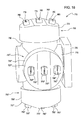
- FIGS. 17 and 18 illustrate a sprayer nozzle apparatus 710 of an agricultural sprayer (not shown) according to another embodiment.
- the sprayer nozzle apparatus 710 includes features similar to the sprayer nozzle apparatus 10 of FIGS. 1 and 2 , and therefore, like components have been given like reference numerals plus 700 and only the differences between the sprayer nozzle apparatuses 10 and 710 will be discussed in detail below.
- the sprayer nozzle apparatus 710 includes an adjustable apparatus housing 715 having a fluid inlet 725 and supporting four nozzle connectors 730, 730', 730", 730"'. More or less nozzle connectors 730, 730', 730", 730"' may be used.
- the nozzle connectors 730, 730', 730", 730"' support a plurality of sprayer nozzle cartridges 750, 750', 750", 750"'.
- the sprayer nozzle cartridges 750, 750', 750", 750"' include a cylindrically-shaped cartridge housing 755, 755', 755", 755"' having an overall convex surface 757, 757', 757", 757"'.
- a first nozzle tip 760, 760', 760", 760"', a second nozzle tip 775, 775', 775", 775"', and a third nozzle tip 790, 790', 790", 790"' are coupled to the cylindrically-shaped cartridge housing 755, 755', 755", 755"' in a linear pattern.
- This disclosure contemplates that the nozzle tips (760, 775, 790), (760', 775', 790'), (760", 775", 790"), (760"', 775"', 790"') may be coupled to the cylindrically-shaped cartridge housing 755, 755', 755", 755"' in any pattern (e.g., non-linear, circular, square).
- nozzle connectors 730, 730', 730", 730"' and the cylindrically-shaped cartridge housing 755, 755', 755", 755"' may be any shape (e.g., square, rectangular, oblong).
- FIGS. 19-21 illustrate a sprayer nozzle apparatus 810 of an agricultural sprayer (not shown) according to another embodiment.
- the sprayer nozzle apparatus 810 includes features similar to the sprayer nozzle apparatus 10 of FIGS. 1 and 2 , and therefore, like components have been given like reference numerals plus 800 and only the differences between the sprayer nozzle apparatuses 10 and 810 will be discussed in detail below.
- the sprayer nozzle apparatus 810 includes an adjustable apparatus housing 815 having a fluid inlet 825 and supporting four nozzle connectors 830, 830', 830", 830"'. More or less nozzle connectors 830, 830', 830", 830"' may be used.
- the nozzle connectors 830, 830', 830", 830"' have protrusions 832, 832', 832", 832"' that are received by a sprayer nozzle cartridge 850 ( FIG. 20 ).
- the sprayer nozzle cartridge 850 includes slots 852 for releaseably engaging the protrusions 832.
- the sprayer nozzle cartridges 850 include a cylindrically-shaped cartridge housing 855 having an overall convex surface 857.
- a first nozzle tip 860 having a first flow path 865, a second nozzle tip 875 having a second flow path 880, and a third nozzle tip 890 having a third flow path 895 are coupled to the cylindrically-shaped cartridge housing 855 in a linear pattern.
- the nozzle tips 860, 875, 890 may be coupled to the cylindrically-shaped cartridge housing 855 in any pattern (e.g., non-linear, circular, square).
- the nozzle connectors 830, 830', 830", 830"' FIG. 19
- the cylindrically-shaped cartridge housing 855 may be any shape (e.g., square, rectangular, oblong).
Landscapes
- Catching Or Destruction (AREA)
- Special Spraying Apparatus (AREA)
- Nozzles (AREA)
- Spray Control Apparatus (AREA)
Abstract
Description
- The present disclosure generally relates to agricultural sprayers, and more particularly to a sprayer nozzle apparatus adapted for receiving a fluid from a spray line of an agricultural sprayer, the sprayer nozzle apparatus comprising: an apparatus housing; a control element rotatably coupled to the apparatus housing; and a plurality of nozzle connectors comprising a plurality of supply paths, the plurality of nozzle connectors coupled to the apparatus housing.
- In order to spray a fluid (e.g., fertilizer, pesticide, fungicide, insecticide) onto agricultural crops, agricultural sprayers commonly include a sprayer nozzle apparatus. The sprayer nozzle apparatus commonly includes a nozzle connector for supporting a nozzle having an orifice. The geometry of the orifice influences the flow rate, droplet size, and spray pattern. The flow rate through the orifice is mainly a function of the orifice geometry and the fluid pressure at the orifice (i.e., pressure just prior to the orifice). Since the orifice geometry is typically fixed, the most common way to influence the flow rate through the nozzle is by changing fluid pressure. Changing the fluid pressure at the nozzle to influence flow rate changes has become common place on sprayers in order to allow for variable vehicle speed. The flow rate is changed in proportion to the vehicle speed in order to keep the application rate the same.
- However, using the traditional fixed orifice nozzle has some limitations. The pressure versus flow relationship is a squared function. To double the flow requires increasing the pressure by a factor of four times. Unfortunately, changing pressure also changes atomization dynamics resulting in an impact on spray quality. Spray quality characteristics, namely, droplet size and spray angle, both become smaller as pressure increases. These changes can negatively impact spray deposit and spray drift. So, the need for the ability to change nozzles on the go has emerged.
- It is therefore one object of the invention to provide a sprayer nozzle apparatus of above mentioned type which overcomes one or more of the above mentioned problems.
- The problem will be solved by the teaching of independent claim 1. Further advantageous embodiments will be described in the accompanying claims.
- Accordingly, a sprayer nozzle apparatus of above mentioned type comprises a control element which is configured to receive fluid from the spray line and selectively communicate fluid to at least one of the plurality of supply paths of one of the plurality of nozzle connectors in a first position and to at least one of the plurality of supply paths of another of the plurality of nozzle connectors in a second position.
- In one embodiment, a sprayer nozzle apparatus is disclosed. The sprayer nozzle apparatus is adapted for receiving a fluid from a spray line of an agricultural sprayer. The sprayer nozzle apparatus includes an apparatus housing. A control element is rotatably coupled to the apparatus housing. A first nozzle connector having a first supply path and a second supply path is coupled to the apparatus housing. A second nozzle connector having a third supply path and a fourth supply path is coupled to the apparatus housing. The control element is configured to receive fluid from the spray line and selectively communicate fluid to at least one of the first supply path and the second supply path in a first position and to at least one of the third supply path and the fourth supply path in a second position.
- In another embodiment, a sprayer nozzle apparatus is disclosed. The sprayer nozzle apparatus is adapted for receiving a fluid from a spray line of an agricultural sprayer. The sprayer nozzle apparatus includes an apparatus housing. A control element is rotatably coupled to the apparatus housing. A plurality of nozzle connectors having a plurality of supply paths are coupled to the apparatus housing. The control element is configured to receive fluid from the spray line and selectively communicate fluid to at least one of the plurality of supply paths of one of the plurality of nozzle connectors in a first position and to at least one of the plurality of supply paths of another of the plurality of nozzle connectors in a second position.
- In yet another embodiment, a sprayer nozzle apparatus is disclosed. The sprayer nozzle apparatus is adapted for receiving a fluid from a spray line of an agricultural sprayer. The sprayer nozzle apparatus includes an apparatus housing. A control element is rotatably coupled to the apparatus housing. A first nozzle connector having a first supply path and a second supply path is coupled to the apparatus housing. A second nozzle connector having a third supply path and a fourth supply path is coupled to the apparatus housing.
- Accordingly, one embodiment relates to a sprayer nozzle apparatus adapted for receiving a fluid from a spray line of an agricultural sprayer, the sprayer nozzle apparatus comprising: an apparatus housing; a control element rotatably coupled to the apparatus housing; a first nozzle connector comprising a first supply path and a second supply path, the first nozzle connector coupled to the apparatus housing; and a second nozzle connector comprising a third supply path and a fourth supply path, the second nozzle connector coupled to the apparatus housing. The control element is configured to receive fluid from the spray line and selectively communicate fluid to at least one of the first supply path and the second supply path in a first position and to at least one of the third supply path and the fourth supply path in a second position. In the first position, the control element may selectively communicate fluid to the first supply path. In the first position, the control element may selectively communicate fluid to the second supply path. In the first position, the control element further may selectively communicate fluid to both the first supply path and the second supply path. In the second position, the control element may selectively communicate fluid to the third supply path. In the second position, the control element may selectively communicates fluid to the fourth supply path. Further, in the second position, the control element may selectively communicate fluid to both the third supply path and the fourth supply path. The sprayer nozzle apparatus may further comprise a first sprayer nozzle cartridge coupled to the first nozzle connector, the first sprayer nozzle cartridge comprising a first cartridge housing, a first nozzle tip comprising a first flow path in fluid communication with the first supply path, the first nozzle tip coupled to the first cartridge housing, and a second nozzle tip comprising a second flow path in fluid communication with the second supply path, the second nozzle tip coupled to the first cartridge housing. The sprayer nozzle apparatus may further comprise a second sprayer nozzle cartridge coupled to the second nozzle connector, the second sprayer nozzle cartridge comprising a second cartridge housing, a third nozzle tip comprising a third flow path in fluid communication with the third supply path, the third nozzle tip coupled to the second cartridge housing, and a fourth nozzle tip comprising a fourth flow path in fluid communication with the fourth supply path, the fourth nozzle tip coupled to the second cartridge housing.
- Accordingly another embodiment relates to a sprayer nozzle apparatus adapted for receiving a fluid from a spray line of an agricultural sprayer, the sprayer nozzle apparatus comprising: an apparatus housing; a control element rotatably coupled to the apparatus housing; and a plurality of nozzle connectors comprising a plurality of supply paths, the plurality of nozzle connectors coupled to the apparatus housing; wherein the control element is configured to receive fluid from the spray line and selectively communicate fluid to at least one of the plurality of supply paths of one of the plurality of nozzle connectors in a first position and to at least one of the plurality of supply paths of another of the plurality of nozzle connectors in a second position. In the first position, the control element may selectively communicate fluid to more than one of the plurality of supply paths. In the second position, the control element may selectively communicate fluid to more than one of the plurality of supply paths. The spray nozzle apparatus may further comprise a plurality of sprayer nozzle cartridges coupled to the plurality of nozzle connectors, the plurality of sprayer nozzle cartridges comprising a cartridge housing, a plurality of nozzle tips comprising a plurality of flow paths in fluid communication with the plurality of supply paths, the plurality of nozzle tips coupled to the cartridge housing.
- Accordingly, yet another embodiment relates to a sprayer nozzle apparatus adapted for receiving a fluid from a spray line of an agricultural sprayer, the sprayer nozzle apparatus comprising: an apparatus housing; a control element rotatably coupled to the apparatus housing; a first nozzle connector comprising a first supply path and a second supply path, the first nozzle connector coupled to the apparatus housing; a second nozzle connector comprising a third supply path and a fourth supply path, the second nozzle connector coupled to the apparatus housing; a first sprayer nozzle cartridge coupled to the first nozzle connector, the first sprayer nozzle cartridge comprising a first cartridge housing, a first nozzle tip comprising a first flow path in fluid communication with the first supply path, the first nozzle tip coupled to the first cartridge housing, and a second nozzle tip comprising a second flow path in fluid communication with the second supply path, the second nozzle tip coupled to the first cartridge housing; and a second sprayer nozzle cartridge coupled to the second nozzle connector, the second sprayer nozzle cartridge comprising a second cartridge housing, a third nozzle tip comprising a third flow path in fluid communication with the third supply path, the third nozzle tip coupled to the second cartridge housing, and a fourth nozzle tip comprising a fourth flow path in fluid communication with the fourth supply path, the fourth nozzle tip coupled to the second cartridge housing; wherein the control element is configured to receive fluid from the spray line and selectively communicate fluid to at least one of the first supply path and the second supply path in a first position and to at least one of the third supply path and the fourth supply path in a second position. In the first position, the control element may selectively communicate fluid to the first supply path. In the first position, the control element may selectively communicate fluid to the second supply path. In the first position, the control element may selectively communicate fluid to both the first supply path and the second supply path. In the second position, the control element may selectively communicate fluid to the third supply path. In the second position, the control element may selectively communicate fluid to the fourth supply path. In the second position, the control element may selectively communicate fluid to both the third supply path and the fourth supply path.
- A first sprayer nozzle cartridge is coupled to the first nozzle connector. The first sprayer nozzle cartridge has a first cartridge housing and a first nozzle tip with a first flow path in fluid communication with the first supply path. The first nozzle tip is coupled to the first cartridge housing. The first sprayer nozzle cartridge has a second nozzle tip with a second flow path in fluid communication with the second supply path. The second nozzle tip is coupled to the first cartridge housing.
- A second sprayer nozzle cartridge is coupled to the second nozzle connector. The second sprayer nozzle cartridge has a second cartridge housing and a third nozzle tip with a third flow path in fluid communication with the third supply path. The third nozzle tip is coupled to the second cartridge housing. The second sprayer nozzle cartridge has a fourth nozzle tip with a fourth flow path in fluid communication with the fourth supply path. The fourth nozzle tip is coupled to the second cartridge housing. The control element is configured to receive fluid from the spray line and selectively communicate fluid to at least one of the first supply path and the second supply path in a first position and to at least one of the third supply path and the fourth supply path in a second position.
-
FIG. 1 is a perspective view of a sprayer nozzle apparatus including a plurality of sprayer nozzle cartridges according to one embodiment. -
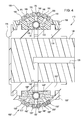
FIG. 2 is a sectional view taken along lines 2-2 ofFIG. 1 . -
FIG. 3 is a perspective view of a sprayer nozzle apparatus including a plurality of sprayer nozzle cartridges according to another embodiment. -
FIG. 4 is a sectional view taken along lines 4-4 ofFIG. 3 . -
FIG. 5 is an enlarged perspective view of the sprayer nozzle cartridge ofFIG. 3 . -
FIG. 6 is an enlarged sectional view taken along lines 6-6 ofFIG. 5 . -
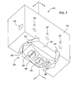
FIG. 7 is a perspective view of a sprayer nozzle apparatus including a sprayer nozzle cartridge according to yet another embodiment. -
FIG. 8 is an enlarged sectional view taken along lines 8-8 ofFIG. 7 . -
FIG. 9 is an enlarged sectional view taken along lines 9-9 ofFIG. 7 . -
FIG. 10 is a sectional view of a sprayer nozzle apparatus including a sprayer nozzle cartridge according to another embodiment. -
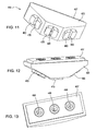
FIG. 11 is a perspective view of a sprayer nozzle cartridge according to yet another embodiment. -
FIG. 12 is a perspective view of the sprayer nozzle cartridge ofFIG. 11 . -
FIG. 13 is a bottom view of the sprayer nozzle cartridge ofFIG. 11 . -
FIG. 14 is a perspective view of a sprayer nozzle apparatus including a plurality of sprayer nozzle cartridges according to another embodiment. -
FIG. 15 is an enlarged bottom view of the sprayer nozzle cartridge ofFIG. 14 . -
FIG. 16 is a perspective view of a sprayer nozzle apparatus including a plurality of sprayer nozzle cartridges according to yet another embodiment. -
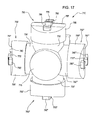
FIG. 17 is a perspective view of a sprayer nozzle apparatus including a plurality of sprayer nozzle cartridges according to another embodiment. -
FIG. 18 is an enlarged right side view of the sprayer nozzle apparatus ofFIG. 17 . -
FIG. 19 is a perspective view of a portion of a sprayer nozzle apparatus according to yet another embodiment. -
FIG. 20 is a perspective view of a sprayer nozzle cartridge according to another embodiment. -
FIG. 21 is a perspective view of the sprayer nozzle cartridge ofFIG. 20 . - Before any embodiments are explained in detail, it is to be understood that the disclosure is not limited in its application to the details of construction and the arrangement of components set forth in the following description or illustrated in the following drawings. The disclosure is capable of other embodiments and of being practiced or of being carried out in various ways.
-
FIG. 1 illustrates asprayer nozzle apparatus 10 of an agricultural sprayer (not shown) according to one embodiment. The illustratedsprayer nozzle apparatus 10 includes anadjustable apparatus housing 15. - A
control element 20 is rotatably coupled to theadjustable apparatus housing 15 enabling theadjustable apparatus housing 15 to rotate relative to thecontrol element 20. Exemplarily, thecontrol element 20 has threefluid inlets 25. The threefluid inlets 25 are in fluid communication with a spray line containing a valve or valves (not shown) of an agricultural sprayer. Other types ofcontrol elements 20 are contemplated by this disclosure (e.g., ball valve). - Exemplarily, four
nozzle connectors adjustable apparatus housing 15. With reference toFIG. 2 , thenozzle connectors first supply path nozzle connectors 30' and 30"'), asecond supply path nozzle connectors 30' and 30"'), and athird supply path nozzle connectors 30' and 30"'), respectively. Referring toFIG. 1 , thenozzle connectors slots nozzle connector 30"') for receiving asprayer nozzle cartridge - The
sprayer nozzle cartridges protrusions nozzle cartridge 50"') for releaseably engaging theslots FIG. 2 , thesprayer nozzle cartridges cartridge housing nozzle cartridges 50' and 50"'), respectively. Afirst nozzle tip nozzle cartridges 50' and 50"') having afirst flow path nozzle cartridges 50' and 50"') and afirst orifice nozzle cartridges 50' and 50"') is coupled to thecartridge housings first flow path first supply path second nozzle tip nozzle cartridges 50' and 50"') having asecond flow path nozzle cartridges 50' and 50"') and asecond orifice nozzle cartridges 50' and 50"') is coupled to thecartridge housing second flow path second supply path third nozzle tip nozzle cartridges 50' and 50"') having athird flow path nozzle cartridges 50' and 50"') and athird orifice nozzle cartridges 50' and 50"') is coupled to thecartridge housing third flow path third supply path - In operation, the
control element 20 receives fluid from the spray line and, in a first position, selectively communicates fluid to thefirst supply path 35, thesecond supply path 40, and thethird supply path 45, thereby communicating fluid to thefirst flow path 65, thesecond flow path 80, and thethird flow path 95, respectively. Thecontrol element 20 may selectively communicate fluid to more than onesupply path supply paths control element 20 may changesupply paths nozzle tips orifices adjustable apparatus housing 15 may rotate while the agricultural sprayer is stationary or moving. - The
adjustable apparatus housing 15 rotates manually, remotely, or automatically to a second position where thecontrol element 20 selectively communicates fluid to the supply paths 35', 40', 45', thereby communicating fluid to the flow paths 65', 80', 95'. Thecontrol element 20 may selectively communicate fluid to more than one supply path 35', 40', 45' or to none of the supply paths 35', 40', 45' depending on the orientation of the valve, or valves, in the spray line. It is contemplated by this disclosure that thecontrol element 20 may change supply paths 35', 40', 45' while the agricultural sprayer is stationary or moving. It is also contemplated that the nozzle tips 60', 75', 90' may have orifices 70', 85', 100' with varying geometries in order to allow for varying vehicle speed and/or desired spray qualities. - The
adjustable apparatus housing 15 rotates manually, remotely, or automatically to a third position where thecontrol element 20 selectively communicates fluid to thesupply paths 35", 40", 45", thereby communicating fluid to theflow paths 65", 80", 95". Thecontrol element 20 may selectively communicate fluid to more than onesupply path 35", 40", 45" or to none of thesupply paths 35", 40", 45" depending on the orientation of the valve, or valves, in the spray line. It is contemplated by this disclosure that thecontrol element 20 may changesupply paths 35", 40", 45" while the agricultural sprayer is stationary or moving. It is also contemplated that thenozzle tips 60", 75", 90" may haveorifices 70", 85", 100" with varying geometries in order to allow for varying vehicle speed and/or desired spray qualities. - The
adjustable apparatus housing 15 rotates manually, remotely, or automatically to a fourth position where thecontrol element 20 selectively communicates fluid to the supply paths of thenozzle cartridge 50"', thereby communicating fluid to the respective flow paths of thenozzle cartridge 50"'. Thecontrol element 20 may selectively communicate fluid to more than one supply path of thenozzle cartridges 50"' or to none of the supply paths of thenozzle cartridge 50"' depending on the orientation of the valve, or valves, in the spray line. It is contemplated by this disclosure that thecontrol element 20 may change supply paths of thenozzle cartridge 50"' while the agricultural sprayer is stationary or moving. It is also contemplated that the nozzle tips of thenozzle cartridge 50"' may have orifices (not shown) with varying geometries in order to allow for varying vehicle speed and/or desired spray qualities. -
FIGS. 3-6 illustrate asprayer nozzle apparatus 110 of an agricultural sprayer (not shown) according to another embodiment. Thesprayer nozzle apparatus 110 includes features similar to thesprayer nozzle apparatus 10 ofFIGS. 1 and2 , and therefore, like components have been given like reference numerals plus 100 and only the differences between thesprayer nozzle apparatuses - With reference to
FIGS. 3 and4 , exemplarily, acontrol element 120 has onefluid inlet 125. Thefluid inlet 125 is in fluid communication with a spray line (not shown) of an agricultural sprayer. The spray line may have a valve (not shown). - Referring to
FIG. 4 ,sprayer nozzle cartridges ball valve sprayer cartridges 150' and 150"'), respectively, having anadjustment portion sprayer cartridges 150' and 150"), that receives fluid from thefluid inlet 125. Thesprayer nozzle cartridges first supply path sprayer cartridges 150' and 150"'), asecond supply path sprayer cartridges 150' and 150"') and athird supply path sprayer cartridges 150' and 150"'). Alternatively, theball valves - In operation, in a first position, the
adjustment portion 136 is oriented by a positioning device (not shown) so theball valve 134 selectively communicates fluid to at least one of thefirst supply path 135, thesecond supply path 140, and thethird supply path 145, thereby communicating fluid to at least one of afirst flow path 165, asecond flow path 180, and athird flow path 195, respectively. - In a second position, the adjustment portion within the cartridge 150' is oriented by a positioning device (not shown) so the ball valve within the cartridge 150' selectively communicates fluid to at least one of the supply paths within the cartridge 150', thereby communicating fluid to at least one of a first flow path (not shown) within the cartridge 150', a second flow path (not shown) within the cartridge 150', and a third flow path (not shown) within the cartridge 150', respectively.
- In a third position, the adjustment portion within the
cartridge 150" is oriented by a positioning device (not shown) so theball valve 134" selectively communicates fluid to at least one of thesupply paths 135", 140", 145", thereby communicating fluid to at least one of afirst flow path 165", asecond flow path 180", and athird flow path 195", respectively. - In a fourth position, the
adjustment portion 136"' is oriented by a positioning device (not shown) so the ball valve within thecartridge 150"' selectively communicates fluid to at least one of the supply paths within the cartridge 150', thereby communicating fluid to at least one of a first flow path within the cartridge 150', a second flow path within the cartridge 150', and a third flow path within the cartridge 150', respectively. -
FIGS. 7-9 illustrate asprayer nozzle apparatus 210 of an agricultural sprayer (not shown) according to another embodiment. Thesprayer nozzle apparatus 210 includes features similar to thesprayer nozzle apparatus 10 ofFIGS. 1 and2 , and therefore, like components have been given like reference numerals plus 200 and only the differences between thesprayer nozzle apparatuses - Referring to
FIG. 7 , thesprayer nozzle apparatus 210 includes anapparatus housing 215 having afluid inlet 225 and anair inlet 227. With reference toFIGS. 8 and9 , thesprayer nozzle apparatus 210 includes anadjustable control element 220 configured to control fluid flow. Exemplarily, theadjustable control element 220 has three air-actuatedpoppets 221 each with a first o-ring 222 and a second o-ring 223. Aspring 224 biases thepoppet 221 to prevent fluid flow. Acap 226 is threadably engaged with theapparatus housing 215 to secure thespring 224 within theapparatus housing 215. - With further reference to
FIG. 7 , anozzle connector 230 having opposedslots 232 for receiving asprayer nozzle cartridge 250 is coupled to theapparatus housing 215. Thesprayer nozzle cartridge 250 includesprotrusions 252 for releaseably engaging theslots 232. - In operation, air is selectively passed through the
air inlet 227 in order to activate one or more of thepoppets 221 by counteracting the biasing force of thespring 224. Fluid is passed through thefluid inlet 225 and theadjustable control element 220 selectively communicates fluid to at least one of thefirst flow path 265, thesecond flow path 280, and thethird flow path 295. Theadjustable control element 220 may selectively communicate fluid to more than oneflow path flow paths -
FIG. 10 illustrates asprayer nozzle apparatus 310 of an agricultural sprayer (not shown) according to another embodiment. Thesprayer nozzle apparatus 310 includes features similar to thesprayer nozzle apparatus 10 ofFIGS. 1 and2 , and therefore, like components have been given like reference numerals plus 300 and only the differences between thesprayer nozzle apparatuses - The
sprayer nozzle apparatus 310 includes acontrol element 320 configured to control fluid flow. Exemplarily, thecontrol element 320 has arotor 321 with a plurality ofslots 323. - In operation, the
slots 323 of thecontrol element 320 selectively communicate fluid to none or at least one of afirst flow path 365, 365', asecond flow path 380, 380', and athird flow path 395, 395'. In a first position, theslots 323 of thecontrol element 320 may selectively communicate fluid to more than oneflow path flow paths slots 323 of thecontrol element 320 may selectively communicate fluid to more than one flow path 365', 380', 395' or to none of the flow paths 365', 380', 395'. -
FIGS. 11-13 illustrate asprayer nozzle cartridge 450 of an agricultural sprayer (not shown) according to another embodiment. Thesprayer nozzle cartridge 450 includes features similar to thesprayer nozzle cartridge 50 ofFIGS. 1 and2 , and therefore, like components have been given like reference numerals plus 400 and only the differences between thesprayer nozzle cartridges - The
sprayer nozzle cartridge 450 includes acartridge housing 455 having ahousing extension 457 that couples to a sprayer nozzle apparatus (not shown). -
FIGS 14 and 15 illustrate asprayer nozzle apparatus 510 of an agricultural sprayer (not shown) according to another embodiment. Thesprayer nozzle apparatus 510 includes features similar to thesprayer nozzle apparatus 10 ofFIGS. 1 and2 , and therefore, like components have been given like reference numerals plus 500 and only the differences between thesprayer nozzle apparatuses - The
sprayer nozzle apparatus 510 includes anadjustable apparatus housing 515 for supporting fournozzle connectors less nozzle connectors nozzle connectors sprayer nozzle cartridges sprayer nozzle cartridges cartridge housing first nozzle tip second nozzle tip third nozzle tip cartridge housing cartridge housing nozzle connectors cartridge housings -
FIG. 16 illustrates asprayer nozzle apparatus 610 of an agricultural sprayer (not shown) according to another embodiment. Thesprayer nozzle apparatus 610 includes features similar to thesprayer nozzle apparatus 10 ofFIGS. 1 and2 , and therefore, like components have been given like reference numerals plus 600 and only the differences between thesprayer nozzle apparatuses - The
sprayer nozzle apparatus 610 includes anadjustable apparatus housing 615 for supporting fournozzle connectors less nozzle connectors nozzle connectors sprayer nozzle cartridges sprayer nozzle cartridges cartridge housing first nozzle tip second nozzle tip third nozzle tip cartridge housing cartridge housing nozzle connector cartridge housing -
FIGS. 17 and18 illustrate asprayer nozzle apparatus 710 of an agricultural sprayer (not shown) according to another embodiment. Thesprayer nozzle apparatus 710 includes features similar to thesprayer nozzle apparatus 10 ofFIGS. 1 and2 , and therefore, like components have been given like reference numerals plus 700 and only the differences between thesprayer nozzle apparatuses - Referring to
FIG. 18 , thesprayer nozzle apparatus 710 includes anadjustable apparatus housing 715 having afluid inlet 725 and supporting fournozzle connectors less nozzle connectors nozzle connectors sprayer nozzle cartridges sprayer nozzle cartridges cartridge housing convex surface first nozzle tip second nozzle tip third nozzle tip cartridge housing cartridge housing nozzle connectors cartridge housing -
FIGS. 19-21 illustrate asprayer nozzle apparatus 810 of an agricultural sprayer (not shown) according to another embodiment. Thesprayer nozzle apparatus 810 includes features similar to thesprayer nozzle apparatus 10 ofFIGS. 1 and2 , and therefore, like components have been given like reference numerals plus 800 and only the differences between thesprayer nozzle apparatuses - With reference to
FIG. 19 , thesprayer nozzle apparatus 810 includes anadjustable apparatus housing 815 having afluid inlet 825 and supporting fournozzle connectors less nozzle connectors nozzle connectors protrusions FIG. 20 ). Referring toFIG. 21 , thesprayer nozzle cartridge 850 includesslots 852 for releaseably engaging theprotrusions 832. - With further reference to
FIG. 20 , exemplarily, thesprayer nozzle cartridges 850 include a cylindrically-shapedcartridge housing 855 having an overallconvex surface 857. Afirst nozzle tip 860 having afirst flow path 865, asecond nozzle tip 875 having asecond flow path 880, and athird nozzle tip 890 having athird flow path 895 are coupled to the cylindrically-shapedcartridge housing 855 in a linear pattern. This disclosure contemplates that thenozzle tips cartridge housing 855 in any pattern (e.g., non-linear, circular, square). This disclosure also contemplates that thenozzle connectors FIG. 19 ) and the cylindrically-shapedcartridge housing 855 may be any shape (e.g., square, rectangular, oblong). - While the disclosure has been illustrated and described in detail in the drawings and foregoing description, such illustration and description is to be considered as exemplary and not restrictive in character, it being understood that illustrative embodiments have been shown and described and that all changes and modifications that come within the spirit of the disclosure are desired to be protected. It will be noted that alternative embodiments of the present disclosure may not include all of the features described yet still benefit from at least some of the advantages of such features. Those of ordinary skill in the art may readily devise their own implementations that incorporate one or more of the features of the present disclosure and fall within the spirit and scope of the present invention as defined by the appended claims.
Claims (12)
- A sprayer nozzle apparatus (10) adapted for receiving a fluid from a spray line of an agricultural sprayer, the sprayer nozzle apparatus (10) comprising: an apparatus housing (15); a control element (20) rotatably coupled to the apparatus housing (15); and a plurality of nozzle connectors (30, 30") comprising a plurality of supply paths (35, 35", 40, 40", 45, 45"), the plurality of nozzle connectors (30, 30") coupled to the apparatus housing (15); wherein the control element (20) is configured to receive fluid from the spray line and selectively communicate fluid to at least one of the plurality of supply paths (35, 40, 45) of one of the plurality of nozzle connectors (30) in a first position and to at least one of the plurality of supply paths (35", 40", 45") of another of the plurality of nozzle connectors (30") in a second position.
- The sprayer nozzle apparatus (10) of claim 1, wherein, in the first position, the control element (20) selectively communicates fluid to more than one of the plurality of supply paths (35, 40, 45).
- The sprayer nozzle apparatus (10) of claim 1 or 2, wherein, in the second position, the control element (20) selectively communicates fluid to more than one of the plurality of supply paths (35", 40", 45").
- The sprayer nozzle apparatus (10) of one of the claims 1 to 3, further comprising a plurality of sprayer nozzle cartridges (50, 50") coupled to the plurality of nozzle connectors (30, 30"), the plurality of sprayer nozzle cartridges (50, 50") comprising a cartridge housing (55, 55"), a plurality of nozzle tips (60, 60", 75, 75", 90, 90") comprising a plurality of flow paths (65, 65", 80, 80", 95, 95") in fluid communication with the plurality of supply paths (35, 35", 40, 40", 45, 45"), the plurality of nozzle tips (60, 60", 75, 75", 90, 90") coupled to the cartridge housing (55, 55").
- A sprayer nozzle apparatus (10) of one of the foregoing claims, wherein the plurality of nozzle connectors (30, 30") comprising a first nozzle connector (30) comprising a first supply path (35) and a second supply path (40), the first nozzle connector (30) coupled to the apparatus housing (15); and a second nozzle connector (30") comprising a third supply path (35") and a fourth supply path (40"), the second nozzle connector (30") coupled to the apparatus housing (15); wherein the control element (20) is configured to receive fluid from the spray line and selectively communicate fluid to at least one of the first supply path (35) and the second supply path (40) in a first position and to at least one of the third supply path (35") and the fourth supply path (40") in a second position.
- The sprayer nozzle apparatus (10) of claim 6, wherein, in the first position, the control element (20) selectively communicates fluid to both the first supply path (35) and the second supply path (40).
- The sprayer nozzle apparatus (10) of claim 6 or 7, wherein, in the second position, the control element (20) selectively communicates fluid to both the third supply path (35") and the fourth supply path (40").
- The sprayer nozzle apparatus (10) of one of the claims 5 to 7, further comprising a first sprayer nozzle cartridge (50) coupled to the first nozzle connector (30), the first sprayer nozzle cartridge (50) comprising a first cartridge housing (55), a first nozzle tip (60) comprising a first flow path (65) in fluid communication with the first supply path (35), the first nozzle tip (60) coupled to the first cartridge housing (55), and a second nozzle tip (75) comprising a second flow path (80) in fluid communication with the second supply path (40), the second nozzle tip (75) coupled to the first cartridge housing (55).
- The sprayer nozzle apparatus (10) of one of the claims 5 to 8, further comprising a second sprayer nozzle cartridge (50") coupled to the second nozzle connector (30"), the second sprayer nozzle cartridge (50") comprising a second cartridge housing (55"), a third nozzle tip (60") comprising a third flow path (65") in fluid communication with the third supply path (35"), the third nozzle tip (60") coupled to the second cartridge housing (55"), and a fourth nozzle tip (75") comprising a fourth flow path (80") in fluid communication with the fourth supply path (40"), the fourth nozzle tip (75") coupled to the second cartridge housing (55").
- A sprayer nozzle apparatus (10) of claim 1, wherein the plurality of nozzle connectors (30, 30") comprising: a first nozzle connector (30) comprising a first supply path (35) and a second supply path (40), the first nozzle connector (30) coupled to the apparatus housing (15); a second nozzle connector (30") comprising a third supply path (35") and a fourth supply path (40"), the second nozzle connector (30") coupled to the apparatus housing (15); a first sprayer nozzle cartridge (50) coupled to the first nozzle connector (30), the first sprayer nozzle cartridge (50) comprising a first cartridge housing (55), a first nozzle tip (60) comprising a first flow path (65) in fluid communication with the first supply path (35), the first nozzle tip (60) coupled to the first cartridge housing (55), and a second nozzle tip (75) comprising a second flow path (80) in fluid communication with the second supply path (40), the second nozzle tip (75) coupled to the first cartridge housing (55); and a second sprayer nozzle cartridge (50") coupled to the second nozzle connector (30"), the second sprayer nozzle cartridge (50") comprising a second cartridge housing (55"), a third nozzle tip (60") comprising a third flow path (65") in fluid communication with the third supply path (35"), the third nozzle tip (60") coupled to the second cartridge housing (55"), and a fourth nozzle tip (75") comprising a fourth flow path (80") in fluid communication with the fourth supply path (40"), the fourth nozzle tip (75") coupled to the second cartridge housing (55"); wherein the control element (20) is configured to receive fluid from the spray line and selectively communicate fluid to at least one of the first supply path (35) and the second supply path (40) in a first position and to at least one of the third supply path (35") and the fourth supply path (40") in a second position.
- The sprayer nozzle apparatus (10) of claim 10, wherein in the first position, the control element (20) selectively communicates fluid to the first supply path (35) and/or to the second supply path (40).
- The sprayer nozzle apparatus (10) of claim 10 or 11, wherein, in the second position, the control element (20) selectively communicates fluid to the third supply path (35") and/or to the fourth supply path (40").
Applications Claiming Priority (1)
| Application Number | Priority Date | Filing Date | Title |
|---|---|---|---|
| US13/457,598 US9073070B2 (en) | 2012-04-27 | 2012-04-27 | Sprayer nozzle apparatus |
Publications (3)
| Publication Number | Publication Date |
|---|---|
| EP2656922A2 true EP2656922A2 (en) | 2013-10-30 |
| EP2656922A3 EP2656922A3 (en) | 2016-12-14 |
| EP2656922B1 EP2656922B1 (en) | 2020-09-16 |
Family
ID=48190778
Family Applications (1)
| Application Number | Title | Priority Date | Filing Date |
|---|---|---|---|
| EP13165583.9A Active EP2656922B1 (en) | 2012-04-27 | 2013-04-26 | Sprayer nozzle apparatus |
Country Status (8)
| Country | Link |
|---|---|
| US (1) | US9073070B2 (en) |
| EP (1) | EP2656922B1 (en) |
| CN (1) | CN103372507A (en) |
| AR (1) | AR090796A1 (en) |
| AU (1) | AU2013205390B2 (en) |
| BR (1) | BR102013010109B1 (en) |
| CA (1) | CA2813356C (en) |
| RU (1) | RU2013115909A (en) |
Cited By (1)
| Publication number | Priority date | Publication date | Assignee | Title |
|---|---|---|---|---|
| WO2020201363A1 (en) * | 2019-04-02 | 2020-10-08 | Ecoclean Gmbh | Switching device for high-pressure tools and cleaning device having such a switching device |
Families Citing this family (24)
| Publication number | Priority date | Publication date | Assignee | Title |
|---|---|---|---|---|
| US9113591B2 (en) | 2012-06-18 | 2015-08-25 | Raven Industries, Inc. | Implement for adjustably metering an agricultural field input according to different frame sections |
| US11160204B2 (en) | 2013-03-15 | 2021-11-02 | Raven Industries, Inc. | Localized product injection system for an agricultural sprayer |
| AU2014278310A1 (en) | 2013-06-10 | 2015-12-10 | Raven Industries, Inc. | Localized product injection system for an agricultural sprayer |
| US9781916B2 (en) | 2013-10-17 | 2017-10-10 | Raven Industries, Inc. | Nozzle control system and method |
| US10173236B2 (en) | 2013-10-17 | 2019-01-08 | Raven Industries, Inc. | Nozzle control system and method |
| US9675000B2 (en) | 2014-05-09 | 2017-06-13 | Raven Industries, Inc. | Optical flow sensing application in agricultural vehicles |
| US10189031B2 (en) | 2014-06-20 | 2019-01-29 | Deere & Company | Hybrid flow nozzle and control system |
| AU2015203208B2 (en) | 2014-06-20 | 2017-04-13 | Deere & Company | Hybrid flow nozzle and control system |
| US9884330B2 (en) | 2014-06-20 | 2018-02-06 | Deere & Company | Broadband spray nozzle systems and methods |
| US10773271B2 (en) | 2014-06-20 | 2020-09-15 | Deere & Company | Time varying control of the operation of spray systems |
| USD766399S1 (en) | 2014-10-03 | 2016-09-13 | Deere & Company | Hybrid spray nozzle turret |
| US10518284B2 (en) | 2015-08-04 | 2019-12-31 | Intelligent Agricultural Solutions Llc | Interactive liquid spraying system and method |
| WO2018129323A1 (en) | 2017-01-05 | 2018-07-12 | Raven Industries, Inc. | Localized product injection system and methods for same |
| CA3049421C (en) | 2017-01-05 | 2023-03-14 | Raven Industries, Inc. | Configurable nozzle assembly and methods for same |
| CN108655054A (en) * | 2017-03-28 | 2018-10-16 | 苏州宝时得电动工具有限公司 | Pressure washer liquid outlet switching device and pressure cleaning equipment |
| US11051505B2 (en) | 2018-10-12 | 2021-07-06 | Deere & Company | Multi-fluid spray system and method for agricultural product application |
| US10842143B2 (en) * | 2018-10-12 | 2020-11-24 | Deere & Company | Multi-fluid spray system and method for agricultural product application |
| US11612160B2 (en) | 2019-10-04 | 2023-03-28 | Raven Industries, Inc. | Valve control system and method |
| CN112474084B (en) * | 2020-11-11 | 2022-03-01 | 山东省科学院自动化研究所 | A cavitation jet intelligent nozzle and underwater cleaning robot |
| AU2022382950A1 (en) | 2021-11-05 | 2024-05-16 | Raven Industries, Inc. | Valve priming and depriming |
| CN114146852B (en) * | 2021-11-22 | 2022-11-08 | 江苏迎凯涂装设备有限公司 | Spraying pressure structure with automatic circulating rotary spraying function |
| CN114632737B (en) * | 2022-05-17 | 2022-07-29 | 潍坊工程职业学院 | Multimedia screen with cleaning function |
| CN115046354B (en) * | 2022-06-28 | 2024-08-23 | 珠海格力电器股份有限公司 | Refrigerator and control method thereof |
| CN117619579B (en) * | 2024-01-25 | 2024-04-12 | 山东宙雨消防科技股份有限公司 | Adjustable shower nozzle |
Family Cites Families (18)
| Publication number | Priority date | Publication date | Assignee | Title |
|---|---|---|---|---|
| US2680652A (en) * | 1946-02-15 | 1954-06-08 | Babcock & Wilcox Co | Atomizer |
| FR2184247A5 (en) * | 1972-05-08 | 1973-12-21 | Berthoud Sa | |
| US3779533A (en) * | 1972-06-15 | 1973-12-18 | B Etter | Machine mounted cutting torch |
| US3826431A (en) * | 1973-04-16 | 1974-07-30 | Velsicol Chemical Corp | Multiple spray head |
| FR2290254A1 (en) * | 1974-11-07 | 1976-06-04 | Lestradet M C J | SPRAYING DEVICE FOR SPREADING RAMP INTENDED IN PARTICULAR FOR AGRICULTURAL VEHICLES |
| US4666085A (en) * | 1986-01-09 | 1987-05-19 | Liaw Maw Shinn | Multiple purpose water spray gun |
| US5134961A (en) | 1990-09-10 | 1992-08-04 | The Regents Of The University Of California | Electrically actuated variable flow control system |
| US5183322A (en) * | 1991-04-19 | 1993-02-02 | Spraying Systems Co. | Spray gun with selective hydraulic and air assisted operating modes |
| US5253807A (en) * | 1992-03-17 | 1993-10-19 | Wade Manufacturing Co. | Multi-outlet emitter and method |
| US5884847A (en) * | 1998-05-01 | 1999-03-23 | Christopher; Gilman O. | Multiple nozzle spray head apparatus |
| US6126088A (en) * | 1998-08-04 | 2000-10-03 | Wilger; Wilfred H. | Extended rate range sprayer nozzle system |
| US6123272A (en) * | 1998-10-16 | 2000-09-26 | Coltec Industrial Products Inc. | Nozzle assembly |
| US6749134B2 (en) * | 2001-06-18 | 2004-06-15 | Spraying Systems Co. | Spray nozzle assembly with auxiliary high volume spray nozzle |
| US7124964B2 (en) | 2002-09-13 | 2006-10-24 | Quy Duc Bui | Nozzle with flow rate and droplet size control capability |
| KR100585936B1 (en) * | 2004-07-16 | 2006-06-08 | 탱크테크 (주) | Fire extinguishing apparatus |
| DE102004056867A1 (en) * | 2004-11-25 | 2006-06-01 | John Deere Fabriek Horst B.V. | nozzle device |
| BRPI0612215A2 (en) * | 2005-03-31 | 2016-09-06 | William Henry Richards | portable dispersion and aeration device and lancet for compressed air foam systems and nutrient release systems to a plant |
| US7980490B2 (en) * | 2006-09-27 | 2011-07-19 | Sta-Rite Industries, Llc | Nozzle body apparatus |
-
2012
- 2012-04-27 US US13/457,598 patent/US9073070B2/en active Active
-
2013
- 2013-04-09 RU RU2013115909/13A patent/RU2013115909A/en not_active Application Discontinuation
- 2013-04-18 CA CA2813356A patent/CA2813356C/en active Active
- 2013-04-22 AR ARP130101338A patent/AR090796A1/en unknown
- 2013-04-23 AU AU2013205390A patent/AU2013205390B2/en active Active
- 2013-04-25 BR BR102013010109-5A patent/BR102013010109B1/en active IP Right Grant
- 2013-04-26 CN CN2013101494112A patent/CN103372507A/en active Pending
- 2013-04-26 EP EP13165583.9A patent/EP2656922B1/en active Active
Non-Patent Citations (1)
| Title |
|---|
| None |
Cited By (2)
| Publication number | Priority date | Publication date | Assignee | Title |
|---|---|---|---|---|
| WO2020201363A1 (en) * | 2019-04-02 | 2020-10-08 | Ecoclean Gmbh | Switching device for high-pressure tools and cleaning device having such a switching device |
| US12011727B2 (en) | 2019-04-02 | 2024-06-18 | Ecoclean Gmbh | Switching apparatus for high pressure tools and cleaning apparatus having such a switching apparatus |
Also Published As
| Publication number | Publication date |
|---|---|
| AU2013205390A1 (en) | 2013-11-14 |
| CN103372507A (en) | 2013-10-30 |
| RU2013115909A (en) | 2014-10-20 |
| AR090796A1 (en) | 2014-12-10 |
| BR102013010109A2 (en) | 2016-03-01 |
| EP2656922A3 (en) | 2016-12-14 |
| AU2013205390B2 (en) | 2017-04-20 |
| US9073070B2 (en) | 2015-07-07 |
| BR102013010109B1 (en) | 2021-03-30 |
| CA2813356C (en) | 2020-11-17 |
| EP2656922B1 (en) | 2020-09-16 |
| CA2813356A1 (en) | 2013-10-27 |
| US20130284826A1 (en) | 2013-10-31 |
Similar Documents
| Publication | Publication Date | Title |
|---|---|---|
| EP2659986B1 (en) | Sprayer nozzle cartridge | |
| CA2813356C (en) | Sprayer nozzle apparatus | |
| US10518284B2 (en) | Interactive liquid spraying system and method | |
| US20150115058A1 (en) | Sprayer nozzle system for variable application rates | |
| AU2012265594B2 (en) | Spray pulsing nozzle flow control using rotational step positions | |
| CA2317005C (en) | Extended rate range sprayer nozzle system | |
| EP2606722A1 (en) | Spray head arrangement | |
| CN107969151B (en) | Pressure Control Devices for Liquids | |
| US20190166775A1 (en) | Multi-position sprayer component for spraying implements | |
| WO1999025482A1 (en) | Variable flow control device for precision application | |
| Mercaldi et al. | Flow and pressure regulation for agricultural sprayers using solenoid valves | |
| US9433144B2 (en) | Orifice selector module for liquid fertilizer distribution systems | |
| Bui | VariTarget–A new nozzle with variable flow rate and droplet optimization | |
| US11453016B2 (en) | Stacked pre-orifices for sprayer nozzles | |
| CA3073033C (en) | Stacked pre-orifices for sprayer nozzles | |
| US20240408630A1 (en) | Spray nozzle for an agricultural device, spraying system with said nozzle, an agricultural device with said nozzle and a method for dispensing a liquid | |
| US20160303586A1 (en) | Sprinkler | |
| Sumner | Soybean sprayer application and calibration |
Legal Events
| Date | Code | Title | Description |
|---|---|---|---|
| PUAI | Public reference made under article 153(3) epc to a published international application that has entered the european phase |
Free format text: ORIGINAL CODE: 0009012 |
|
| AK | Designated contracting states |
Kind code of ref document: A2 Designated state(s): AL AT BE BG CH CY CZ DE DK EE ES FI FR GB GR HR HU IE IS IT LI LT LU LV MC MK MT NL NO PL PT RO RS SE SI SK SM TR |
|
| AX | Request for extension of the european patent |
Extension state: BA ME |
|
| PUAL | Search report despatched |
Free format text: ORIGINAL CODE: 0009013 |
|
| AK | Designated contracting states |
Kind code of ref document: A3 Designated state(s): AL AT BE BG CH CY CZ DE DK EE ES FI FR GB GR HR HU IE IS IT LI LT LU LV MC MK MT NL NO PL PT RO RS SE SI SK SM TR |
|
| AX | Request for extension of the european patent |
Extension state: BA ME |
|
| RIC1 | Information provided on ipc code assigned before grant |
Ipc: B05B 1/08 20060101AFI20161104BHEP |
|
| STAA | Information on the status of an ep patent application or granted ep patent |
Free format text: STATUS: REQUEST FOR EXAMINATION WAS MADE |
|
| 17P | Request for examination filed |
Effective date: 20170614 |
|
| RBV | Designated contracting states (corrected) |
Designated state(s): AL AT BE BG CH CY CZ DE DK EE ES FI FR GB GR HR HU IE IS IT LI LT LU LV MC MK MT NL NO PL PT RO RS SE SI SK SM TR |
|
| STAA | Information on the status of an ep patent application or granted ep patent |
Free format text: STATUS: EXAMINATION IS IN PROGRESS |
|
| 17Q | First examination report despatched |
Effective date: 20171026 |
|
| GRAP | Despatch of communication of intention to grant a patent |
Free format text: ORIGINAL CODE: EPIDOSNIGR1 |
|
| STAA | Information on the status of an ep patent application or granted ep patent |
Free format text: STATUS: GRANT OF PATENT IS INTENDED |
|
| INTG | Intention to grant announced |
Effective date: 20200414 |
|
| GRAS | Grant fee paid |
Free format text: ORIGINAL CODE: EPIDOSNIGR3 |
|
| GRAA | (expected) grant |
Free format text: ORIGINAL CODE: 0009210 |
|
| STAA | Information on the status of an ep patent application or granted ep patent |
Free format text: STATUS: THE PATENT HAS BEEN GRANTED |
|
| AK | Designated contracting states |
Kind code of ref document: B1 Designated state(s): AL AT BE BG CH CY CZ DE DK EE ES FI FR GB GR HR HU IE IS IT LI LT LU LV MC MK MT NL NO PL PT RO RS SE SI SK SM TR |
|
| REG | Reference to a national code |
Ref country code: GB Ref legal event code: FG4D |
|
| REG | Reference to a national code |
Ref country code: CH Ref legal event code: EP |
|
| REG | Reference to a national code |
Ref country code: DE Ref legal event code: R096 Ref document number: 602013072533 Country of ref document: DE |
|
| REG | Reference to a national code |
Ref country code: IE Ref legal event code: FG4D |
|
| REG | Reference to a national code |
Ref country code: AT Ref legal event code: REF Ref document number: 1313668 Country of ref document: AT Kind code of ref document: T Effective date: 20201015 |
|
| REG | Reference to a national code |
Ref country code: NL Ref legal event code: FP |
|
| PG25 | Lapsed in a contracting state [announced via postgrant information from national office to epo] |
Ref country code: NO Free format text: LAPSE BECAUSE OF FAILURE TO SUBMIT A TRANSLATION OF THE DESCRIPTION OR TO PAY THE FEE WITHIN THE PRESCRIBED TIME-LIMIT Effective date: 20201216 Ref country code: BG Free format text: LAPSE BECAUSE OF FAILURE TO SUBMIT A TRANSLATION OF THE DESCRIPTION OR TO PAY THE FEE WITHIN THE PRESCRIBED TIME-LIMIT Effective date: 20201216 Ref country code: HR Free format text: LAPSE BECAUSE OF FAILURE TO SUBMIT A TRANSLATION OF THE DESCRIPTION OR TO PAY THE FEE WITHIN THE PRESCRIBED TIME-LIMIT Effective date: 20200916 Ref country code: GR Free format text: LAPSE BECAUSE OF FAILURE TO SUBMIT A TRANSLATION OF THE DESCRIPTION OR TO PAY THE FEE WITHIN THE PRESCRIBED TIME-LIMIT Effective date: 20201217 Ref country code: FI Free format text: LAPSE BECAUSE OF FAILURE TO SUBMIT A TRANSLATION OF THE DESCRIPTION OR TO PAY THE FEE WITHIN THE PRESCRIBED TIME-LIMIT Effective date: 20200916 Ref country code: SE Free format text: LAPSE BECAUSE OF FAILURE TO SUBMIT A TRANSLATION OF THE DESCRIPTION OR TO PAY THE FEE WITHIN THE PRESCRIBED TIME-LIMIT Effective date: 20200916 |
|
| REG | Reference to a national code |
Ref country code: AT Ref legal event code: MK05 Ref document number: 1313668 Country of ref document: AT Kind code of ref document: T Effective date: 20200916 |
|
| PG25 | Lapsed in a contracting state [announced via postgrant information from national office to epo] |
Ref country code: LV Free format text: LAPSE BECAUSE OF FAILURE TO SUBMIT A TRANSLATION OF THE DESCRIPTION OR TO PAY THE FEE WITHIN THE PRESCRIBED TIME-LIMIT Effective date: 20200916 Ref country code: RS Free format text: LAPSE BECAUSE OF FAILURE TO SUBMIT A TRANSLATION OF THE DESCRIPTION OR TO PAY THE FEE WITHIN THE PRESCRIBED TIME-LIMIT Effective date: 20200916 |
|
| REG | Reference to a national code |
Ref country code: LT Ref legal event code: MG4D |
|
| PG25 | Lapsed in a contracting state [announced via postgrant information from national office to epo] |
Ref country code: EE Free format text: LAPSE BECAUSE OF FAILURE TO SUBMIT A TRANSLATION OF THE DESCRIPTION OR TO PAY THE FEE WITHIN THE PRESCRIBED TIME-LIMIT Effective date: 20200916 Ref country code: CZ Free format text: LAPSE BECAUSE OF FAILURE TO SUBMIT A TRANSLATION OF THE DESCRIPTION OR TO PAY THE FEE WITHIN THE PRESCRIBED TIME-LIMIT Effective date: 20200916 Ref country code: PT Free format text: LAPSE BECAUSE OF FAILURE TO SUBMIT A TRANSLATION OF THE DESCRIPTION OR TO PAY THE FEE WITHIN THE PRESCRIBED TIME-LIMIT Effective date: 20210118 Ref country code: LT Free format text: LAPSE BECAUSE OF FAILURE TO SUBMIT A TRANSLATION OF THE DESCRIPTION OR TO PAY THE FEE WITHIN THE PRESCRIBED TIME-LIMIT Effective date: 20200916 Ref country code: RO Free format text: LAPSE BECAUSE OF FAILURE TO SUBMIT A TRANSLATION OF THE DESCRIPTION OR TO PAY THE FEE WITHIN THE PRESCRIBED TIME-LIMIT Effective date: 20200916 Ref country code: SM Free format text: LAPSE BECAUSE OF FAILURE TO SUBMIT A TRANSLATION OF THE DESCRIPTION OR TO PAY THE FEE WITHIN THE PRESCRIBED TIME-LIMIT Effective date: 20200916 |
|
| PG25 | Lapsed in a contracting state [announced via postgrant information from national office to epo] |
Ref country code: IS Free format text: LAPSE BECAUSE OF FAILURE TO SUBMIT A TRANSLATION OF THE DESCRIPTION OR TO PAY THE FEE WITHIN THE PRESCRIBED TIME-LIMIT Effective date: 20210116 Ref country code: PL Free format text: LAPSE BECAUSE OF FAILURE TO SUBMIT A TRANSLATION OF THE DESCRIPTION OR TO PAY THE FEE WITHIN THE PRESCRIBED TIME-LIMIT Effective date: 20200916 Ref country code: AT Free format text: LAPSE BECAUSE OF FAILURE TO SUBMIT A TRANSLATION OF THE DESCRIPTION OR TO PAY THE FEE WITHIN THE PRESCRIBED TIME-LIMIT Effective date: 20200916 Ref country code: AL Free format text: LAPSE BECAUSE OF FAILURE TO SUBMIT A TRANSLATION OF THE DESCRIPTION OR TO PAY THE FEE WITHIN THE PRESCRIBED TIME-LIMIT Effective date: 20200916 Ref country code: ES Free format text: LAPSE BECAUSE OF FAILURE TO SUBMIT A TRANSLATION OF THE DESCRIPTION OR TO PAY THE FEE WITHIN THE PRESCRIBED TIME-LIMIT Effective date: 20200916 |
|
| REG | Reference to a national code |
Ref country code: DE Ref legal event code: R097 Ref document number: 602013072533 Country of ref document: DE |
|
| PG25 | Lapsed in a contracting state [announced via postgrant information from national office to epo] |
Ref country code: SK Free format text: LAPSE BECAUSE OF FAILURE TO SUBMIT A TRANSLATION OF THE DESCRIPTION OR TO PAY THE FEE WITHIN THE PRESCRIBED TIME-LIMIT Effective date: 20200916 |
|
| PLBE | No opposition filed within time limit |
Free format text: ORIGINAL CODE: 0009261 |
|
| STAA | Information on the status of an ep patent application or granted ep patent |
Free format text: STATUS: NO OPPOSITION FILED WITHIN TIME LIMIT |
|
| 26N | No opposition filed |
Effective date: 20210617 |
|
| PG25 | Lapsed in a contracting state [announced via postgrant information from national office to epo] |
Ref country code: DK Free format text: LAPSE BECAUSE OF FAILURE TO SUBMIT A TRANSLATION OF THE DESCRIPTION OR TO PAY THE FEE WITHIN THE PRESCRIBED TIME-LIMIT Effective date: 20200916 Ref country code: SI Free format text: LAPSE BECAUSE OF FAILURE TO SUBMIT A TRANSLATION OF THE DESCRIPTION OR TO PAY THE FEE WITHIN THE PRESCRIBED TIME-LIMIT Effective date: 20200916 |
|
| PG25 | Lapsed in a contracting state [announced via postgrant information from national office to epo] |
Ref country code: IT Free format text: LAPSE BECAUSE OF FAILURE TO SUBMIT A TRANSLATION OF THE DESCRIPTION OR TO PAY THE FEE WITHIN THE PRESCRIBED TIME-LIMIT Effective date: 20200916 |
|
| PG25 | Lapsed in a contracting state [announced via postgrant information from national office to epo] |
Ref country code: MC Free format text: LAPSE BECAUSE OF FAILURE TO SUBMIT A TRANSLATION OF THE DESCRIPTION OR TO PAY THE FEE WITHIN THE PRESCRIBED TIME-LIMIT Effective date: 20200916 |
|
| GBPC | Gb: european patent ceased through non-payment of renewal fee |
Effective date: 20210426 |
|
| PG25 | Lapsed in a contracting state [announced via postgrant information from national office to epo] |
Ref country code: LU Free format text: LAPSE BECAUSE OF NON-PAYMENT OF DUE FEES Effective date: 20210426 |
|
| REG | Reference to a national code |
Ref country code: BE Ref legal event code: MM Effective date: 20210430 |
|
| PG25 | Lapsed in a contracting state [announced via postgrant information from national office to epo] |
Ref country code: CH Free format text: LAPSE BECAUSE OF NON-PAYMENT OF DUE FEES Effective date: 20210430 Ref country code: LI Free format text: LAPSE BECAUSE OF NON-PAYMENT OF DUE FEES Effective date: 20210430 Ref country code: GB Free format text: LAPSE BECAUSE OF NON-PAYMENT OF DUE FEES Effective date: 20210426 |
|
| PG25 | Lapsed in a contracting state [announced via postgrant information from national office to epo] |
Ref country code: IE Free format text: LAPSE BECAUSE OF NON-PAYMENT OF DUE FEES Effective date: 20210426 |
|
| PG25 | Lapsed in a contracting state [announced via postgrant information from national office to epo] |
Ref country code: IS Free format text: LAPSE BECAUSE OF FAILURE TO SUBMIT A TRANSLATION OF THE DESCRIPTION OR TO PAY THE FEE WITHIN THE PRESCRIBED TIME-LIMIT Effective date: 20210116 |
|
| PG25 | Lapsed in a contracting state [announced via postgrant information from national office to epo] |
Ref country code: BE Free format text: LAPSE BECAUSE OF NON-PAYMENT OF DUE FEES Effective date: 20210430 |
|
| PG25 | Lapsed in a contracting state [announced via postgrant information from national office to epo] |
Ref country code: HU Free format text: LAPSE BECAUSE OF FAILURE TO SUBMIT A TRANSLATION OF THE DESCRIPTION OR TO PAY THE FEE WITHIN THE PRESCRIBED TIME-LIMIT; INVALID AB INITIO Effective date: 20130426 |
|
| PG25 | Lapsed in a contracting state [announced via postgrant information from national office to epo] |
Ref country code: CY Free format text: LAPSE BECAUSE OF FAILURE TO SUBMIT A TRANSLATION OF THE DESCRIPTION OR TO PAY THE FEE WITHIN THE PRESCRIBED TIME-LIMIT Effective date: 20200916 |
|
| PG25 | Lapsed in a contracting state [announced via postgrant information from national office to epo] |
Ref country code: MK Free format text: LAPSE BECAUSE OF FAILURE TO SUBMIT A TRANSLATION OF THE DESCRIPTION OR TO PAY THE FEE WITHIN THE PRESCRIBED TIME-LIMIT Effective date: 20200916 |
|
| PG25 | Lapsed in a contracting state [announced via postgrant information from national office to epo] |
Ref country code: MT Free format text: LAPSE BECAUSE OF FAILURE TO SUBMIT A TRANSLATION OF THE DESCRIPTION OR TO PAY THE FEE WITHIN THE PRESCRIBED TIME-LIMIT Effective date: 20200916 |
|
| PGFP | Annual fee paid to national office [announced via postgrant information from national office to epo] |
Ref country code: NL Payment date: 20250427 Year of fee payment: 13 |
|
| PGFP | Annual fee paid to national office [announced via postgrant information from national office to epo] |
Ref country code: DE Payment date: 20250319 Year of fee payment: 13 |
|
| PGFP | Annual fee paid to national office [announced via postgrant information from national office to epo] |
Ref country code: FR Payment date: 20250425 Year of fee payment: 13 |
|
| PG25 | Lapsed in a contracting state [announced via postgrant information from national office to epo] |
Ref country code: TR Free format text: LAPSE BECAUSE OF FAILURE TO SUBMIT A TRANSLATION OF THE DESCRIPTION OR TO PAY THE FEE WITHIN THE PRESCRIBED TIME-LIMIT Effective date: 20200916 |