EP2656818A1 - Absorbable blood vessel stent - Google Patents
Absorbable blood vessel stent Download PDFInfo
- Publication number
- EP2656818A1 EP2656818A1 EP11850312.7A EP11850312A EP2656818A1 EP 2656818 A1 EP2656818 A1 EP 2656818A1 EP 11850312 A EP11850312 A EP 11850312A EP 2656818 A1 EP2656818 A1 EP 2656818A1
- Authority
- EP
- European Patent Office
- Prior art keywords
- blood vessel
- vessel stent
- support strut
- strut
- support
- Prior art date
- Legal status (The legal status is an assumption and is not a legal conclusion. Google has not performed a legal analysis and makes no representation as to the accuracy of the status listed.)
- Granted
Links
Images
Classifications
-
- A—HUMAN NECESSITIES
- A61—MEDICAL OR VETERINARY SCIENCE; HYGIENE
- A61F—FILTERS IMPLANTABLE INTO BLOOD VESSELS; PROSTHESES; DEVICES PROVIDING PATENCY TO, OR PREVENTING COLLAPSING OF, TUBULAR STRUCTURES OF THE BODY, e.g. STENTS; ORTHOPAEDIC, NURSING OR CONTRACEPTIVE DEVICES; FOMENTATION; TREATMENT OR PROTECTION OF EYES OR EARS; BANDAGES, DRESSINGS OR ABSORBENT PADS; FIRST-AID KITS
- A61F2/00—Filters implantable into blood vessels; Prostheses, i.e. artificial substitutes or replacements for parts of the body; Appliances for connecting them with the body; Devices providing patency to, or preventing collapsing of, tubular structures of the body, e.g. stents
- A61F2/82—Devices providing patency to, or preventing collapsing of, tubular structures of the body, e.g. stents
- A61F2/86—Stents in a form characterised by the wire-like elements; Stents in the form characterised by a net-like or mesh-like structure
- A61F2/89—Stents in a form characterised by the wire-like elements; Stents in the form characterised by a net-like or mesh-like structure the wire-like elements comprising two or more adjacent rings flexibly connected by separate members
-
- A—HUMAN NECESSITIES
- A61—MEDICAL OR VETERINARY SCIENCE; HYGIENE
- A61F—FILTERS IMPLANTABLE INTO BLOOD VESSELS; PROSTHESES; DEVICES PROVIDING PATENCY TO, OR PREVENTING COLLAPSING OF, TUBULAR STRUCTURES OF THE BODY, e.g. STENTS; ORTHOPAEDIC, NURSING OR CONTRACEPTIVE DEVICES; FOMENTATION; TREATMENT OR PROTECTION OF EYES OR EARS; BANDAGES, DRESSINGS OR ABSORBENT PADS; FIRST-AID KITS
- A61F2/00—Filters implantable into blood vessels; Prostheses, i.e. artificial substitutes or replacements for parts of the body; Appliances for connecting them with the body; Devices providing patency to, or preventing collapsing of, tubular structures of the body, e.g. stents
- A61F2/82—Devices providing patency to, or preventing collapsing of, tubular structures of the body, e.g. stents
- A61F2/86—Stents in a form characterised by the wire-like elements; Stents in the form characterised by a net-like or mesh-like structure
- A61F2/90—Stents in a form characterised by the wire-like elements; Stents in the form characterised by a net-like or mesh-like structure characterised by a net-like or mesh-like structure
- A61F2/91—Stents in a form characterised by the wire-like elements; Stents in the form characterised by a net-like or mesh-like structure characterised by a net-like or mesh-like structure made from perforated sheets or tubes, e.g. perforated by laser cuts or etched holes
-
- A—HUMAN NECESSITIES
- A61—MEDICAL OR VETERINARY SCIENCE; HYGIENE
- A61F—FILTERS IMPLANTABLE INTO BLOOD VESSELS; PROSTHESES; DEVICES PROVIDING PATENCY TO, OR PREVENTING COLLAPSING OF, TUBULAR STRUCTURES OF THE BODY, e.g. STENTS; ORTHOPAEDIC, NURSING OR CONTRACEPTIVE DEVICES; FOMENTATION; TREATMENT OR PROTECTION OF EYES OR EARS; BANDAGES, DRESSINGS OR ABSORBENT PADS; FIRST-AID KITS
- A61F2/00—Filters implantable into blood vessels; Prostheses, i.e. artificial substitutes or replacements for parts of the body; Appliances for connecting them with the body; Devices providing patency to, or preventing collapsing of, tubular structures of the body, e.g. stents
- A61F2/82—Devices providing patency to, or preventing collapsing of, tubular structures of the body, e.g. stents
- A61F2/86—Stents in a form characterised by the wire-like elements; Stents in the form characterised by a net-like or mesh-like structure
- A61F2/90—Stents in a form characterised by the wire-like elements; Stents in the form characterised by a net-like or mesh-like structure characterised by a net-like or mesh-like structure
- A61F2/91—Stents in a form characterised by the wire-like elements; Stents in the form characterised by a net-like or mesh-like structure characterised by a net-like or mesh-like structure made from perforated sheets or tubes, e.g. perforated by laser cuts or etched holes
- A61F2/915—Stents in a form characterised by the wire-like elements; Stents in the form characterised by a net-like or mesh-like structure characterised by a net-like or mesh-like structure made from perforated sheets or tubes, e.g. perforated by laser cuts or etched holes with bands having a meander structure, adjacent bands being connected to each other
-
- A—HUMAN NECESSITIES
- A61—MEDICAL OR VETERINARY SCIENCE; HYGIENE
- A61L—METHODS OR APPARATUS FOR STERILISING MATERIALS OR OBJECTS IN GENERAL; DISINFECTION, STERILISATION OR DEODORISATION OF AIR; CHEMICAL ASPECTS OF BANDAGES, DRESSINGS, ABSORBENT PADS OR SURGICAL ARTICLES; MATERIALS FOR BANDAGES, DRESSINGS, ABSORBENT PADS OR SURGICAL ARTICLES
- A61L31/00—Materials for other surgical articles, e.g. stents, stent-grafts, shunts, surgical drapes, guide wires, materials for adhesion prevention, occluding devices, surgical gloves, tissue fixation devices
- A61L31/02—Inorganic materials
- A61L31/022—Metals or alloys
-
- A—HUMAN NECESSITIES
- A61—MEDICAL OR VETERINARY SCIENCE; HYGIENE
- A61L—METHODS OR APPARATUS FOR STERILISING MATERIALS OR OBJECTS IN GENERAL; DISINFECTION, STERILISATION OR DEODORISATION OF AIR; CHEMICAL ASPECTS OF BANDAGES, DRESSINGS, ABSORBENT PADS OR SURGICAL ARTICLES; MATERIALS FOR BANDAGES, DRESSINGS, ABSORBENT PADS OR SURGICAL ARTICLES
- A61L31/00—Materials for other surgical articles, e.g. stents, stent-grafts, shunts, surgical drapes, guide wires, materials for adhesion prevention, occluding devices, surgical gloves, tissue fixation devices
- A61L31/14—Materials characterised by their function or physical properties, e.g. injectable or lubricating compositions, shape-memory materials, surface modified materials
-
- A—HUMAN NECESSITIES
- A61—MEDICAL OR VETERINARY SCIENCE; HYGIENE
- A61L—METHODS OR APPARATUS FOR STERILISING MATERIALS OR OBJECTS IN GENERAL; DISINFECTION, STERILISATION OR DEODORISATION OF AIR; CHEMICAL ASPECTS OF BANDAGES, DRESSINGS, ABSORBENT PADS OR SURGICAL ARTICLES; MATERIALS FOR BANDAGES, DRESSINGS, ABSORBENT PADS OR SURGICAL ARTICLES
- A61L31/00—Materials for other surgical articles, e.g. stents, stent-grafts, shunts, surgical drapes, guide wires, materials for adhesion prevention, occluding devices, surgical gloves, tissue fixation devices
- A61L31/14—Materials characterised by their function or physical properties, e.g. injectable or lubricating compositions, shape-memory materials, surface modified materials
- A61L31/148—Materials at least partially resorbable by the body
-
- A—HUMAN NECESSITIES
- A61—MEDICAL OR VETERINARY SCIENCE; HYGIENE
- A61F—FILTERS IMPLANTABLE INTO BLOOD VESSELS; PROSTHESES; DEVICES PROVIDING PATENCY TO, OR PREVENTING COLLAPSING OF, TUBULAR STRUCTURES OF THE BODY, e.g. STENTS; ORTHOPAEDIC, NURSING OR CONTRACEPTIVE DEVICES; FOMENTATION; TREATMENT OR PROTECTION OF EYES OR EARS; BANDAGES, DRESSINGS OR ABSORBENT PADS; FIRST-AID KITS
- A61F2/00—Filters implantable into blood vessels; Prostheses, i.e. artificial substitutes or replacements for parts of the body; Appliances for connecting them with the body; Devices providing patency to, or preventing collapsing of, tubular structures of the body, e.g. stents
- A61F2/82—Devices providing patency to, or preventing collapsing of, tubular structures of the body, e.g. stents
- A61F2002/825—Devices providing patency to, or preventing collapsing of, tubular structures of the body, e.g. stents having longitudinal struts
-
- A—HUMAN NECESSITIES
- A61—MEDICAL OR VETERINARY SCIENCE; HYGIENE
- A61F—FILTERS IMPLANTABLE INTO BLOOD VESSELS; PROSTHESES; DEVICES PROVIDING PATENCY TO, OR PREVENTING COLLAPSING OF, TUBULAR STRUCTURES OF THE BODY, e.g. STENTS; ORTHOPAEDIC, NURSING OR CONTRACEPTIVE DEVICES; FOMENTATION; TREATMENT OR PROTECTION OF EYES OR EARS; BANDAGES, DRESSINGS OR ABSORBENT PADS; FIRST-AID KITS
- A61F2/00—Filters implantable into blood vessels; Prostheses, i.e. artificial substitutes or replacements for parts of the body; Appliances for connecting them with the body; Devices providing patency to, or preventing collapsing of, tubular structures of the body, e.g. stents
- A61F2/82—Devices providing patency to, or preventing collapsing of, tubular structures of the body, e.g. stents
- A61F2/86—Stents in a form characterised by the wire-like elements; Stents in the form characterised by a net-like or mesh-like structure
- A61F2/90—Stents in a form characterised by the wire-like elements; Stents in the form characterised by a net-like or mesh-like structure characterised by a net-like or mesh-like structure
- A61F2/91—Stents in a form characterised by the wire-like elements; Stents in the form characterised by a net-like or mesh-like structure characterised by a net-like or mesh-like structure made from perforated sheets or tubes, e.g. perforated by laser cuts or etched holes
- A61F2/915—Stents in a form characterised by the wire-like elements; Stents in the form characterised by a net-like or mesh-like structure characterised by a net-like or mesh-like structure made from perforated sheets or tubes, e.g. perforated by laser cuts or etched holes with bands having a meander structure, adjacent bands being connected to each other
- A61F2002/9155—Adjacent bands being connected to each other
- A61F2002/91575—Adjacent bands being connected to each other connected peak to trough
-
- A—HUMAN NECESSITIES
- A61—MEDICAL OR VETERINARY SCIENCE; HYGIENE
- A61F—FILTERS IMPLANTABLE INTO BLOOD VESSELS; PROSTHESES; DEVICES PROVIDING PATENCY TO, OR PREVENTING COLLAPSING OF, TUBULAR STRUCTURES OF THE BODY, e.g. STENTS; ORTHOPAEDIC, NURSING OR CONTRACEPTIVE DEVICES; FOMENTATION; TREATMENT OR PROTECTION OF EYES OR EARS; BANDAGES, DRESSINGS OR ABSORBENT PADS; FIRST-AID KITS
- A61F2210/00—Particular material properties of prostheses classified in groups A61F2/00 - A61F2/26 or A61F2/82 or A61F9/00 or A61F11/00 or subgroups thereof
- A61F2210/0004—Particular material properties of prostheses classified in groups A61F2/00 - A61F2/26 or A61F2/82 or A61F9/00 or A61F11/00 or subgroups thereof bioabsorbable
-
- A—HUMAN NECESSITIES
- A61—MEDICAL OR VETERINARY SCIENCE; HYGIENE
- A61F—FILTERS IMPLANTABLE INTO BLOOD VESSELS; PROSTHESES; DEVICES PROVIDING PATENCY TO, OR PREVENTING COLLAPSING OF, TUBULAR STRUCTURES OF THE BODY, e.g. STENTS; ORTHOPAEDIC, NURSING OR CONTRACEPTIVE DEVICES; FOMENTATION; TREATMENT OR PROTECTION OF EYES OR EARS; BANDAGES, DRESSINGS OR ABSORBENT PADS; FIRST-AID KITS
- A61F2250/00—Special features of prostheses classified in groups A61F2/00 - A61F2/26 or A61F2/82 or A61F9/00 or A61F11/00 or subgroups thereof
- A61F2250/0014—Special features of prostheses classified in groups A61F2/00 - A61F2/26 or A61F2/82 or A61F9/00 or A61F11/00 or subgroups thereof having different values of a given property or geometrical feature, e.g. mechanical property or material property, at different locations within the same prosthesis
- A61F2250/0039—Special features of prostheses classified in groups A61F2/00 - A61F2/26 or A61F2/82 or A61F9/00 or A61F11/00 or subgroups thereof having different values of a given property or geometrical feature, e.g. mechanical property or material property, at different locations within the same prosthesis differing in diameter
-
- A—HUMAN NECESSITIES
- A61—MEDICAL OR VETERINARY SCIENCE; HYGIENE
- A61F—FILTERS IMPLANTABLE INTO BLOOD VESSELS; PROSTHESES; DEVICES PROVIDING PATENCY TO, OR PREVENTING COLLAPSING OF, TUBULAR STRUCTURES OF THE BODY, e.g. STENTS; ORTHOPAEDIC, NURSING OR CONTRACEPTIVE DEVICES; FOMENTATION; TREATMENT OR PROTECTION OF EYES OR EARS; BANDAGES, DRESSINGS OR ABSORBENT PADS; FIRST-AID KITS
- A61F2250/00—Special features of prostheses classified in groups A61F2/00 - A61F2/26 or A61F2/82 or A61F9/00 or A61F11/00 or subgroups thereof
- A61F2250/0058—Additional features; Implant or prostheses properties not otherwise provided for
- A61F2250/0067—Means for introducing or releasing pharmaceutical products into the body
- A61F2250/0068—Means for introducing or releasing pharmaceutical products into the body the pharmaceutical product being in a reservoir
Definitions
- the invention relates to a medical instrument, and in particular, to an absorbable blood vessel stent for treatment of blood vessel lumen stenosis.
- the stents After implanted into the human body, the stents may provide durable mechanical support for the blood vessel, thereby preventing the blood vessel from elastically recoiling and reducing the re-stenosis rate of the diseased blood vessel.
- the stents since the stents were permanently implanted into the human body, the stents as foreign substances may cause intimal hyperplasia and quite high re-stenosis rate of the blood vessel.
- the application of stents treated with drugs has reduced the blood vessel re-stenosis rate to about 10%.
- the drug stents still existed inside the human body permanently.
- the stents have great differences with vascular tissues in terms of mechanical properties, which may cause chronic injury of the blood vessel or cause blood vessel medial atrophy and intimal hyperplasia at the late stage. This may also finally cause blood vessel re-stenosis, thereby limiting the further reduction of the blood vessel re-stenosis rate.
- the implantation of blood vessel stents with fixed sizes may hinder the gradual increase of the blood vessel, being unable to meet the requirement on the growth of children.
- both of the above intervention treatment technologies for blood vessel stenosis have drawbacks.
- the metal stent-including a bare stent or drug stent - may dilate the narrow blood vessel and provide a durable mechanical support, however, the blood vessel intima may be injured during expansion of the metal stents, which may induce blood vessel intimal hyperplasia and lead to re-stenosis.
- the metal stents further have the drawbacks of thrombosis, coagulation complication, flexibility mismatching, and increase of the re-stenosis occurrence rate at late stage if they permanently remain inside the human body.
- the ideal situation should be that, at the initial stage, the blood vessel stent provides a sufficient support to the blood vessel, and meanwhile releases drugs to treat the diseased blood vessel. And after the treating function is accomplished, the blood vessel stent is gradually absorbed so as to prevent the re-stenosis.
- the blood vessel stent made of macromolecular polymer materials, such as polylactic acid; and the other kind is the blood vessel stent made of metal materials, such as magnesium alloy and iron.
- the degradable macromolecular materials have obvious defects in terms of mechanical properties, and so the application thereof is limited.
- the macromolecular polymer materials have low mechanical properties and insufficient strength.
- the wall thickness of the stent must be increased.
- the stent with a thick wall may hinder the flowing of the blood.
- the retraction rate of the macromolecular polymer material stents is quite high when expanded by the balloons, and so the expansion ratio of the diameter of the stent after expanded with respect to the diameter of the blood vessel is larger than that of the metal material stents, which may cause greater injury to the blood vessel during the dilation.
- the X-ray visibility of the macromolecular polymer material stents inside the human body is poor, and so it is difficult to locate and observe the stents during the implantation.
- magnesium alloy material is poor in mechanical properties and fast in corrosion rate.
- the magnesium alloy material has good bio-compatibility.
- the maximum elongation rate of the magnesium alloy stents is low, which brings great challenge to the structural design of the magnesium alloy stents, and so it is difficult to ensure the good mechanical properties of the stents.
- the corrosion rate of the magnesium alloy stents is too fast, so a complex material manufacture process must be adopted to control the rate by which the magnesium alloy stents are absorbed by the human body.
- Iron is an essential element for the human body, and pure iron has good bio-compatibility and mechanical properties simultaneously. Compared with the polymer stents or magnesium alloy stents having a same wall thickness, the iron stents may provide a sufficient radial support for the diseased blood vessel at the diseased position. However, the corrosion rate of the pure iron is relatively slow. Thus the iron stents of common structure design may be absorbed by the human body after a long time, during which process the diameter of the blood vessel may be restrained. As a result it cannot meet the requirement on the gradual increase of the blood vessel for children.
- an urgent problem to be solved at present is how to design a blood vessel stent that can accelerate the absorption process of the human body and simultaneously ensure the mechanical properties thereof.
- the technical problem to be solved in the invention is to provide a blood vessel stent which is used for treating blood vessel stenosis and is absorbable by the human body, so as to solve the problem in the prior art that two properties of the stents are hard to balance. That is to balance the mechanical properties of the absorbable blood vessel stents and to have the blood vessel stent be absorbed as fast as possible.
- an absorbable blood vessel stent having a proximal end and a distal end, a pattern structure that is tubular and expandable is formed between the proximal end and the distal end, where the pattern structure comprises a plurality of support struts and connection bridges.
- the connection bridge or support strut comprises a linear, a U-shaped , or an S-shaped segment, and at least one through slot or through hole is provided on at least one support strut.
- the strut has at least one neck portion located near the slot or hole, where the neck portion has the minimum width along the strut.
- one or more through slots are provided parallel to the linear segment of the strut. Any one of the through slots and the linear segment form two branches, and the branches have a minimum width along the strut.
- the plurality of slots are arrayed along the support strut with a bridge arranged between the adjacent through slots, and the bridge has the minimum width on the support strut.
- a neck portion is formed at an end of the branch, the neck portion has the minimum width along the support strut; and a broad portion is formed at the other end of the branch, where the broad portion has the maximum width on the branch.
- the support strut or the joint of two support struts has a curved segment thereon, and at least one through hole is provided on the curved segment.
- the support strut comprises at least one truss structure, where the truss structure comprises a plurality of through slots or through holes, and a bridge is arranged between the adjacent slots or holes.
- the truss structure further has a plurality of side bridges on both sides thereof, and the bridge and the side bridge have the minimum width along the support strut.
- the pattern structure further comprises several annular wavy bands where two adjacent bands are coupled together.
- the annular wavy bands are interconnected by the connection bridges of the pattern structure.
- Each annular band comprises a plurality of arched support pieces connected head to tail and a plurality of wave valley segments. Two adjacent arched support pieces are connected by such a wave valley segment.
- the arched support piece comprises a wave peak segment, a first support strut, and a second support strut.
- the first support strut and the second support strut are connected by the peak segment.
- At least one through slot or through hole is provided at the first support strut, the second support strut, the peak segment or valley segment.
- the first strut and the second strut are symmetric with each other.
- the minimum width on the support strut is 0.05 to 0.1 mm.
- the blood vessel stent is made of iron or iron alloy material.
- the absorbable blood vessel stent of the invention with a special structure can become corroded and decompose only within a short time, which reduces the re-stenosis probability of the diseased blood vessel, contributes to continuous growth and expansion after the repair of the diseased blood vessel, and meets requirements of clinical use; 2.
- the structure of the absorbable blood vessel stent of the invention does not sacrifice the mechanical properties of the blood vessel stent. While promoting the corrosion and disintegration of the blood vessel stent, the blood vessel stent maintains the sufficient radial support force for the diseased blood vessel before disintegration; and 3.
- the absorbable blood vessel stent of the invention may be made of an iron tube, the wall thickness of the blood vessel stent is not increased compared with a common permanent blood vessel stent, and the stent may be delivered by adopting a balloon catheter which is commonly used for clinical application.
- the cost of application of absorbable blood vessel stent is reduced, and the clinically applicable scope of the absorbable blood vessel stent is extended.
- the absorbable blood vessel stent in the first embodiment of the invention is a thin iron tube with a diameter of 2mm and a wall thickness of 0.1 mm before laser engraving.
- Fig. 2 shows a blood vessel stent 100 that is formed after the iron tube is engraved by laser and that is not expanded yet.
- the blood vessel stent 100 has a proximal end and a distal end, and a expandable pattern structure exists between the proximal end and the distal end.
- the stent consists of four annular wavy bands in total, where each annular band is formed by eight arched support pieces which are connected head to tail to form a circle. Each annular wavy band is connected to another by linear connection bridges 1.
- the blood vessel stent 100 may also consist of two, three, five or more annular bands. Also, there may be more than or less than eight arched support pieces included in each annular band.
- the connection bridge 1 may also be in another shape, such as a U shape or S shape.
- the blood vessel stent 100 may be made of iron alloy or other materials.
- the pattern structure in a known absorbable blood vessel stent or other blood vessel stents can be used in the absorbable blood vessel stent, as long as it consists of support struts and connection bridges and the support struts are formed and structured in the way described herein and in accordance with the principles of the invention.
- Fig. 3 is a plane diagram of an annular band after the blood vessel stent 100 is slightly expanded radially and Fig. 4 is a first embodiment of an arched support piece of the annular band.
- the arched support piece comprises a first support strut 2 and a second support strut 3 with an angle to each other, and the first support bar 2 and the second support strut 3 essentially are single linear sections and are connected by the wave peak segment 4 at the top of the arch.
- the first support strut 2 and the second support strut 3 may be symmetric, or may be asymmetric.
- the support strut may not only be in the shape of single straight line segment shown in Fig. 4 , but also be in a curved shape containing several straight segments, for example, a U shape, a S shape, or a combination of these shapes and other shapes. Only the straight segments therein need to be configured in a similar manner.
- Adjacent arched support pieces are connected by the wave valley segments at the bottom.
- the valley segments of one annular wavy band may be connected with a peak segment of the adjacent annular wavy band by the connection bridge 1.
- the peak segment of a single annular band is closer to the distal end of the stent than the valley segment.
- the peak segments 4 and valley segments may be in different shapes, and may also be symmetrical structures.
- a first through slot 5 is provided in the central portion of the first strut 2
- a second through slot 6 is provided in the central portion of the second strut 3. Both ends of the first slot 5 and the second slot 6 are respectively close to positions of the peak segment 4 and the valley segment which are connected with corresponding struts.
- the first slot 5 divides the middle portion of the first strut 2 into a first branch 7 and a second branch 8.
- a neck portion 9 is provided at the position where the first branch 7 is close to the peak segment 4.
- the neck portion 9 is the position with the minimum width on the first branch 7, wherein the minimum width may be in the range from 0.05 to 0.1 mm.
- a broad portion 10 is arranged at the other end of the first branch 7, and is the position with the maximum width on the first branch 7, wherein the width of the broad portion 10 may be in the range from 0.1 to 0.2 mm. On the first branch 7, the width from the neck portion 9 to the broad portion 10 may change gradually.
- Another broad portion 11 is provided at the position opposite to the neck portion 9 on the second branch 8, and the width may be in the range from 0.1 to 0.2 mm, and the broad portion 11 is the position with the maximum width on the second branch 8.
- Another neck portion 12 with a width between 0.05 and 0.1 mm is provided at the position opposite to the broad portion 10 on the second branch 8, and is the position with the minimum width on the second branch 8. On the second branch 8, the width may change gradually from the neck portion 12 to the broad portion 11.
- the broad portion 11 may protect the neck portion 9 from large deformation
- the broad portion 10 may protect the neck portion 12 from large deformation.
- the neck portion 9 and the neck portion 12 may break first because of corrosion. This would cause the first support strut 2 to completely break, and the blood vessel stent 100 may come apart at this place in a shorter time.
- the second support strut 3 has the structure and technical effect similar to the first support strut 2, and breaks from corrosion in the human body after approximately the same time.
- the first branch 7 and the second branch 8 located at both sides of the slot 5 may be deformed simultaneously.
- the broad portion 11 is close to and aligned with the neck portion 9.
- the width of the broad portion 11 is larger, and so it is hard to be deformed during the expansion process. Therefore, the stress for deforming the first strut 2 is mainly distributed at the broad portion 11, while the neck portion 9 at the opposite side receives a smaller force. That is to say, the neck portion 9 may avoid large deformation because of the protection of the broad portion 11.
- the first strut 2 still keeps a good mechanical strength. Therefore, the slot 5 does not do harm to the overall mechanical properties of the blood vessel stent.
- Fig. 5 is a schematic diagram of a second embodiment of an arched support piece on the absorbable blood vessel stent of the invention, which is roughly the same with the first embodiment. The differences lie in that: two longitudinally arranged slots 13 and 14 are arranged on the first strut 202, and divide the first strut 202 into two branches. Two longitudinally arranged slots similar to the slots 13 and 14 are also arranged on the second strut 302 which is connected with the first strut 202, and also divide the second strut 302 into two branches. Likewise, a neck portion 15 is arranged at the end where a branch is close to the peak segment, while another neck portion 17 is arranged at the opposite end of the other branch.
- a bridge 16 exists between the slot 13 and the slot 14 to separate the slots 13 and 14.
- the width of the bridge 16 in the peripheral direction of the blood vessel stent 100 is the same as the widths of the neck portion 15 and the neck portion 17, and corresponds to the minimum width along the first support strut 202.
- Neck portions which are as wide as the neck portions 15 and 17 are also respectively arranged at the corresponding positions of the both branches on the second strut 302.
- the two slots are also separated by another bridge as wide as the bridge 16.
- Using a bridge to connect two branches of the struts may increase the structural strength and stability of the support struts.
- the blood vessel stent 100 starts corrosion when implanted into the human body.
- the first strut 202, the neck portions 15 and 17 and the bridge 16 with the minimum width may break first, which causes the first strut 202 to completely break.
- the second strut 302 has a structure and size similar to the first strut 202, the two struts may simultaneously and completely break, so that the blood vessel stent 100 may break apart at this place in a shorter time.
- Fig. 6 is a schematic diagram of a third embodiment of an arched support piece on the absorbable blood vessel stent of the invention
- the first strut 203 of the support piece is the same as the first strut 2 in the first embodiment of the support piece in shape and structure
- the support piece also has a second strut 303, but the difference lies in that, no through slot is provided on the second strut 303.
- the third embodiment may improve the overall strength of the blood vessel stent, while the time from corrosion to disassembly of the blood vessel stent inside the human body is almost the same.
- Fig. 7 is a schematic diagram of a fourth embodiment of an arched support piece on the absorbable blood vessel stent of the invention.
- the fouth embodiment of the support piece is similar to the first embodiment, and the differences lie in that the linear or straight line segment of the first strut 204 has a through slot 18 which is shorter than the above slot 13 and which is provided at a central position in the linear segment. It is preferred to set the length of the slot 18 to be one to three times of the width of the first strut 204. Another through slot similar to the slot 18 is also provided at the central position of the second strut 304.
- the slot 18 divides the linear segment of the first strut 204 into two branches, that is, a first branch 19 and a second branch 20, and the two branches are the parts having the minimum width on the strut 204, that is, the neck portions.
- the first branch 19 and the second branch 20 will break first when the blood vessel stent is corroded, which will cause the first strut 204 to break completely.
- the second strut 304 has effects similar to the first strut 204, and also has a similar slots and branches. The two struts may simultaneously fully break, so that the blood vessel stent may disassemble at this place in a shorter time.
- the widths of the first branch 19 and the second branch 20 may be substantially uniform, the widths thereof may be equal, and are chosen from the range of 0.05 to 0.1 mm.
- Fig. 8 is a schematic diagram of a fifth embodiment of an arched support piece on the absorbable blood vessel stent of the invention.
- the fifth embodiment of the support piece is similar to the fourth embodiment, and the differences lie in that the first strut 205 of the support piece has a slightly S-shaped curved segment at the central position thereof. A round or approximately round through hole 212 is arranged at this location.
- the second strut 305 is also slightly S-shaped, and also has such a through hole in the central position thereof. Thus the strength of the first strut 205 and the strut 305 is better than that of fourth embodiment.
- Neck portions 21 and 22 are respectively arranged at both sides of the through hole 212.
- the widths of the neck portions 21 and 22 represent the minimum widths on the first support strut 205, such as 0.05 mm. The positions of the neck portions 21 and 22 will be first corroded and break, which causes the first strut 205 to break completely.
- similar neck portions with the minimum widths are arranged at both sides of the through hole of the second strut 305, so that the blood vessel stent can break and disassemble in a shorter time.
- Fig. 9 is a schematic diagram of a sixth embodiment of an arched support piece on the absorbable blood vessel stent of the invention.
- the sixth embodiment of the support piece is similar to the third embodiment, and the differences lie in that no through slots are provided on the first strut 206 and the second strut 306.
- An approximate fan-shaped through hole 23 is provided at the peak segment connecting the first strut 206 and the second strut 306.
- the through hole 23 divides the peak segment into two arched portions with small widths, that is, a first arched portion 24 at the outer side and a second arched portion 25 at the inner side.
- the radial widths of the first arched portion 24 and the second arched portion 25 are basically equal, and the first arched portion 24 and the second arched portion 25 are the positions with the minimum widths of the whole support piece. These are neck portions, and the widths thereof are approximately 0.05 to 0.1 mm. Therefore, when the blood vessel stent is corroded inside the human body, the two arched portions 24 and 25 will break first, which causes the support piece to break completely at the wave peak, so that the blood vessel stent can disassemble at this place in a shorter time.
- Adjacent arched support pieces are connected at a valley segment, so that similar structures with the through hole 23, the first arched portion 24, and the second arched portion 25 can be arranged at the valley segment. Since the blood vessel stent is corroded, the adjacent arched support pieces are disconnected at the valley segment in a shorter time.
- the blood vessel stent adopts a pattern structure of another form, then similar through slot, outer arched portion, and inner arched portion configurations may also be arranged at the curved segment of the support strut.
- the stress at the inner side is larger than the stress at the outer side of the peak or valley segment. Therefore, the second arched portion 25 at the inner side may be wider than the first arched portion 24 at the outer side, so as to enable the whole arched support piece to keep a good mechanical stability.
- Fig. 10 is a schematic diagram of a seventh embodiment of an arched support piece on the absorbable blood vessel stent of the invention.
- the seventh embodiment of the support piece is similar to the second embodiment, and the differences lie in that a truss structure composed of a plurality of bridge arms is arranged at the central portion of the first strut 207.
- the truss structure forms four through holes 26, 27, 28, and 29, while bridges 30, 31, and 32 are formed between the holes 26, 27, 28, and 29.
- the second strut 307 also has a similar truss structure at the central portion thereof.
- Several side bridges are provided along the outer sides of the central portion of the first strut 207 and the second strut 307.
- Each side bridge and bridge 30, 31, and 32 has a minimum width on the support strut, for example, the width may be chosen from 0.05 to 0.1 mm.
- the truss structures at the middle positions of the first strut 207 and the second strut 307 enable the blood vessel stent to use minimum amounts of material. Since the truss structure makes the metal amount reduced, it is easier for the blood vessel stent to be absorbed completely by the human body in a shorter time. The existence of each through hole increases the surface area of the blood vessel stent, the corrosion area is increased, and thus the disintegration of the blood vessel stent is accelerated.
- the special structure thereof not only improve the properties of the iron blood vessel stent, but also can accelerate the corrosion and decomposition, compared to stents made of other absorbable materials.
- the special structure thereof After blood vessel intimal cells wholly wrap the blood vessel stent, particular positions of this blood vessel stent can be corroded in a shorter time, so as to make the whole blood vessel stent break into several parts in the peripheral direction. In this way, the radial restraint of the stent for the blood vessel is removed, and thus normal increase of the blood vessel at this place will not be hindered.
- the blood vessel stent since the blood vessel stent is divided into several parts after disassembly, and is wrapped by intimal cells, the remnant structures are smaller, which helps the vascular tissues absorb the remnant parts of the blood vessel stent.
- the blood vessel stent of this structure may not weaken the overall mechanical property of the blood vessel stent, and the radial support force before disassembly can still meet the requirement of the diseased blood vessel.
- the blood vessel stent of the invention the time that the human body absorbs the stent is reduced, and meanwhile, the blood vessel stent is ensured to have a sufficient mechanical stability.
- the invention has the following advantages:
Landscapes
- Health & Medical Sciences (AREA)
- Heart & Thoracic Surgery (AREA)
- Vascular Medicine (AREA)
- Life Sciences & Earth Sciences (AREA)
- Animal Behavior & Ethology (AREA)
- General Health & Medical Sciences (AREA)
- Public Health (AREA)
- Veterinary Medicine (AREA)
- Engineering & Computer Science (AREA)
- Biomedical Technology (AREA)
- Surgery (AREA)
- Epidemiology (AREA)
- Oral & Maxillofacial Surgery (AREA)
- Cardiology (AREA)
- Transplantation (AREA)
- Optics & Photonics (AREA)
- Physics & Mathematics (AREA)
- Chemical & Material Sciences (AREA)
- Inorganic Chemistry (AREA)
- Media Introduction/Drainage Providing Device (AREA)
- Prostheses (AREA)
Abstract
Description
- The invention relates to a medical instrument, and in particular, to an absorbable blood vessel stent for treatment of blood vessel lumen stenosis.
- In 1977, the first case of Percutaneous Coronary Intervention (PCI) surgery in the world was accomplished in Switzerland. In this surgery, a balloon was employed to dilate the position of the left anterior descending branch stenosis of the patient, sucessfully. However, the re-stenosis rate of the blood vessel after balloon dilation was very high, over 50%. The main reason was that, after the blood vessel was dilated and the external force was removed, the blood vessel may elastically recoil. In the 1980s, blood vessel stents widely used for coronary artery were invented. There were blood vessel metal stents mainly made of stainless steel, cobalt-chromium alloy or nickel-titanium alloy. After implanted into the human body, the stents may provide durable mechanical support for the blood vessel, thereby preventing the blood vessel from elastically recoiling and reducing the re-stenosis rate of the diseased blood vessel. However, since the stents were permanently implanted into the human body, the stents as foreign substances may cause intimal hyperplasia and quite high re-stenosis rate of the blood vessel.
- Since 2003, the application of stents treated with drugs has reduced the blood vessel re-stenosis rate to about 10%. However, the drug stents still existed inside the human body permanently. As foreign objects the stents have great differences with vascular tissues in terms of mechanical properties, which may cause chronic injury of the blood vessel or cause blood vessel medial atrophy and intimal hyperplasia at the late stage. This may also finally cause blood vessel re-stenosis, thereby limiting the further reduction of the blood vessel re-stenosis rate. As for children, the implantation of blood vessel stents with fixed sizes may hinder the gradual increase of the blood vessel, being unable to meet the requirement on the growth of children.
- Both of the above intervention treatment technologies for blood vessel stenosis have drawbacks. When dilating the blood vessel by using balloons, although the short-term effect is good, the re-stenosis rate at the late stage is very high because of elastic recoiling of the blood vessel. When implanting metal stents into the blood vessel, the metal stent-including a bare stent or drug stent - may dilate the narrow blood vessel and provide a durable mechanical support, however, the blood vessel intima may be injured during expansion of the metal stents, which may induce blood vessel intimal hyperplasia and lead to re-stenosis. The metal stents further have the drawbacks of thrombosis, coagulation complication, flexibility mismatching, and increase of the re-stenosis occurrence rate at late stage if they permanently remain inside the human body.
- In order to solve the above problems, many people begin to pay close attention to the blood vessel stent absorbable by the human body in recent years. After a blood vessel stent is implanted into the human body, the ideal situation should be that, at the initial stage, the blood vessel stent provides a sufficient support to the blood vessel, and meanwhile releases drugs to treat the diseased blood vessel. And after the treating function is accomplished, the blood vessel stent is gradually absorbed so as to prevent the re-stenosis. Using different materials, there are two main kinds of absorbable blood vessel stents. One kind is the blood vessel stent made of macromolecular polymer materials, such as polylactic acid; and the other kind is the blood vessel stent made of metal materials, such as magnesium alloy and iron.
- Recently, scientists have been doing research on making blood vessel stents, for example, a polylactic acid stent, by degradable macromolecular materials, and some research results have started clinical tests. However, compared with the metal materials, the degradable macromolecular materials have obvious defects in terms of mechanical properties, and so the application thereof is limited. When compared with the metal materials, the macromolecular polymer materials have low mechanical properties and insufficient strength. In order to achieve certain radial support, the wall thickness of the stent must be increased. However, after implanted inside the human body, the stent with a thick wall may hinder the flowing of the blood. In addition, the retraction rate of the macromolecular polymer material stents is quite high when expanded by the balloons, and so the expansion ratio of the diameter of the stent after expanded with respect to the diameter of the blood vessel is larger than that of the metal material stents, which may cause greater injury to the blood vessel during the dilation. The X-ray visibility of the macromolecular polymer material stents inside the human body is poor, and so it is difficult to locate and observe the stents during the implantation.
- At present, there are mainly two types of metal materials applied to absorbable blood vessel stents: magnesium alloy material and pure iron material. The magnesium alloy material is poor in mechanical properties and fast in corrosion rate. The magnesium alloy material has good bio-compatibility. However, the maximum elongation rate of the magnesium alloy stents is low, which brings great challenge to the structural design of the magnesium alloy stents, and so it is difficult to ensure the good mechanical properties of the stents. Furthermore, the corrosion rate of the magnesium alloy stents is too fast, so a complex material manufacture process must be adopted to control the rate by which the magnesium alloy stents are absorbed by the human body.
- Iron is an essential element for the human body, and pure iron has good bio-compatibility and mechanical properties simultaneously. Compared with the polymer stents or magnesium alloy stents having a same wall thickness, the iron stents may provide a sufficient radial support for the diseased blood vessel at the diseased position. However, the corrosion rate of the pure iron is relatively slow. Thus the iron stents of common structure design may be absorbed by the human body after a long time, during which process the diameter of the blood vessel may be restrained. As a result it cannot meet the requirement on the gradual increase of the blood vessel for children.
- Therefore, an urgent problem to be solved at present is how to design a blood vessel stent that can accelerate the absorption process of the human body and simultaneously ensure the mechanical properties thereof.
- The technical problem to be solved in the invention is to provide a blood vessel stent which is used for treating blood vessel stenosis and is absorbable by the human body, so as to solve the problem in the prior art that two properties of the stents are hard to balance. That is to balance the mechanical properties of the absorbable blood vessel stents and to have the blood vessel stent be absorbed as fast as possible.
- The technical solutions for solving the technical problem of the invention are as follows: an absorbable blood vessel stent is provided, having a proximal end and a distal end, a pattern structure that is tubular and expandable is formed between the proximal end and the distal end, where the pattern structure comprises a plurality of support struts and connection bridges. The connection bridge or support strut comprises a linear, a U-shaped , or an S-shaped segment, and at least one through slot or through hole is provided on at least one support strut.
- As a further embodiment of the absorbable blood vessel stent of the invention, the strut has at least one neck portion located near the slot or hole, where the neck portion has the minimum width along the strut.
- As a further embodiment of the absorbable blood vessel stent of the invention, one or more through slots are provided parallel to the linear segment of the strut. Any one of the through slots and the linear segment form two branches, and the branches have a minimum width along the strut. The plurality of slots are arrayed along the support strut with a bridge arranged between the adjacent through slots, and the bridge has the minimum width on the support strut.
- As a further embodiment of the absorbable blood vessel stent of the invention, a neck portion is formed at an end of the branch, the neck portion has the minimum width along the support strut; and a broad portion is formed at the other end of the branch, where the broad portion has the maximum width on the branch.
- As a further embodiment of the absorbable blood vessel stent of the invention, the support strut or the joint of two support struts has a curved segment thereon, and at least one through hole is provided on the curved segment.
- As a further embodiment of the absorbable blood vessel stent of the invention, the support strut comprises at least one truss structure, where the truss structure comprises a plurality of through slots or through holes, and a bridge is arranged between the adjacent slots or holes. The truss structure further has a plurality of side bridges on both sides thereof, and the bridge and the side bridge have the minimum width along the support strut.
- As a further embodiment of the absorbable blood vessel stent of the invention, the pattern structure further comprises several annular wavy bands where two adjacent bands are coupled together. The annular wavy bands are interconnected by the connection bridges of the pattern structure. Each annular band comprises a plurality of arched support pieces connected head to tail and a plurality of wave valley segments. Two adjacent arched support pieces are connected by such a wave valley segment. The arched support piece comprises a wave peak segment, a first support strut, and a second support strut. The first support strut and the second support strut are connected by the peak segment. At least one through slot or through hole is provided at the first support strut, the second support strut, the peak segment or valley segment.
- As a further embodiment of the absorbable blood vessel stent of the invention, the first strut and the second strut are symmetric with each other.
- As a further embodiment of the absorbable blood vessel stent of the invention, the minimum width on the support strut is 0.05 to 0.1 mm.
- As a further embodiment of the absorbable blood vessel stent of the invention, the blood vessel stent is made of iron or iron alloy material.
- Compared with the prior art, the invention has the following advantages: 1. The absorbable blood vessel stent of the invention with a special structure can become corroded and decompose only within a short time, which reduces the re-stenosis probability of the diseased blood vessel, contributes to continuous growth and expansion after the repair of the diseased blood vessel, and meets requirements of clinical use; 2. The structure of the absorbable blood vessel stent of the invention does not sacrifice the mechanical properties of the blood vessel stent. While promoting the corrosion and disintegration of the blood vessel stent, the blood vessel stent maintains the sufficient radial support force for the diseased blood vessel before disintegration; and 3. The absorbable blood vessel stent of the invention may be made of an iron tube, the wall thickness of the blood vessel stent is not increased compared with a common permanent blood vessel stent, and the stent may be delivered by adopting a balloon catheter which is commonly used for clinical application. Thus the cost of application of absorbable blood vessel stent is reduced, and the clinically applicable scope of the absorbable blood vessel stent is extended.
-
-
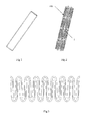
Fig. 1 is a schematic diagram of an absorbable blood vessel stent prior to laser engraving molding according to an embodiment of the present invention; -
Fig. 2 is a schematic diagram of an absorbable blood vessel stent after laser engraving that is not yet expanded according to an embodiment of the present invention; -
Fig. 3 is a plane diagram of an annular wavy band of the blood vessel stent inFig. 2 ; -
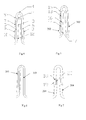
Fig. 4 is a schematic diagram of a first embodiment of an arched support piece of an annular wavy band inFig. 3 ; -
Fig. 5 is a schematic diagram of a second embodiment of an arched support piece of an annular wavy band inFig. 3 ; -
Fig. 6 is a schematic diagram of a third embodiment of an arched support piece of an annular wavy band inFig. 3 ; -
Fig. 7 is a schematic diagram of a fourth embodiment of an arched support piece of an annular wavy band inFig. 3 ; -
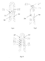
Fig. 8 is a schematic diagram of a fifth embodiment of an arched support piece of an annular wavy band inFig. 3 ; -
Fig. 9 is a schematic diagram of a sixth embodiment of an arched support piece of an annular wavy band inFig. 3 ; and -
Fig. 10 is a schematic diagram of a seventh embodiment of an arched support piece of an annular wavy band inFig. 3 . - To make the purposes, technical solutions and advantages of the invention more clear, the invention will be further described in details as below by embodiments with reference to the drawings. It should be understood that the specific embodiments described herein are only used for explaining the invention, but not for limiting the invention.
- As shown in
Fig. 1 , the absorbable blood vessel stent in the first embodiment of the invention is a thin iron tube with a diameter of 2mm and a wall thickness of 0.1 mm before laser engraving.Fig. 2 shows ablood vessel stent 100 that is formed after the iron tube is engraved by laser and that is not expanded yet. Theblood vessel stent 100 has a proximal end and a distal end, and a expandable pattern structure exists between the proximal end and the distal end. The stent consists of four annular wavy bands in total, where each annular band is formed by eight arched support pieces which are connected head to tail to form a circle. Each annular wavy band is connected to another by linear connection bridges 1. It may be understood that, theblood vessel stent 100 may also consist of two, three, five or more annular bands. Also, there may be more than or less than eight arched support pieces included in each annular band. Theconnection bridge 1 may also be in another shape, such as a U shape or S shape. - The
blood vessel stent 100 may be made of iron alloy or other materials. The pattern structure in a known absorbable blood vessel stent or other blood vessel stents can be used in the absorbable blood vessel stent, as long as it consists of support struts and connection bridges and the support struts are formed and structured in the way described herein and in accordance with the principles of the invention. -
Fig. 3 is a plane diagram of an annular band after theblood vessel stent 100 is slightly expanded radially andFig. 4 is a first embodiment of an arched support piece of the annular band. The arched support piece comprises afirst support strut 2 and asecond support strut 3 with an angle to each other, and thefirst support bar 2 and thesecond support strut 3 essentially are single linear sections and are connected by thewave peak segment 4 at the top of the arch. In order to make the blood vessel stent have different properties, thefirst support strut 2 and thesecond support strut 3 may be symmetric, or may be asymmetric. The support strut may not only be in the shape of single straight line segment shown inFig. 4 , but also be in a curved shape containing several straight segments, for example, a U shape, a S shape, or a combination of these shapes and other shapes. Only the straight segments therein need to be configured in a similar manner. - Adjacent arched support pieces are connected by the wave valley segments at the bottom. The valley segments of one annular wavy band may be connected with a peak segment of the adjacent annular wavy band by the
connection bridge 1. The peak segment of a single annular band is closer to the distal end of the stent than the valley segment. Thepeak segments 4 and valley segments may be in different shapes, and may also be symmetrical structures. - A first through
slot 5 is provided in the central portion of thefirst strut 2, a second through slot 6 is provided in the central portion of thesecond strut 3. Both ends of thefirst slot 5 and the second slot 6 are respectively close to positions of thepeak segment 4 and the valley segment which are connected with corresponding struts. Thefirst slot 5 divides the middle portion of thefirst strut 2 into afirst branch 7 and a second branch 8. A neck portion 9 is provided at the position where thefirst branch 7 is close to thepeak segment 4. The neck portion 9 is the position with the minimum width on thefirst branch 7, wherein the minimum width may be in the range from 0.05 to 0.1 mm. Abroad portion 10 is arranged at the other end of thefirst branch 7, and is the position with the maximum width on thefirst branch 7, wherein the width of thebroad portion 10 may be in the range from 0.1 to 0.2 mm. On thefirst branch 7, the width from the neck portion 9 to thebroad portion 10 may change gradually. - Another
broad portion 11 is provided at the position opposite to the neck portion 9 on the second branch 8, and the width may be in the range from 0.1 to 0.2 mm, and thebroad portion 11 is the position with the maximum width on the second branch 8. Anotherneck portion 12 with a width between 0.05 and 0.1 mm is provided at the position opposite to thebroad portion 10 on the second branch 8, and is the position with the minimum width on the second branch 8. On the second branch 8, the width may change gradually from theneck portion 12 to thebroad portion 11. - When the
blood vessel stent 100 is expanded and deformed, since the strength of thebroad portions neck portions 9 and 12, thebroad portion 11 may protect the neck portion 9 from large deformation, and thebroad portion 10 may protect theneck portion 12 from large deformation. After theblood vessel stent 100 is implanted into the body, since theneck portions 9 and 12 are respectively the parts with the minimum widths on thefirst branch 7 and the second branch 8, the neck portion 9 and theneck portion 12 may break first because of corrosion. This would cause thefirst support strut 2 to completely break, and theblood vessel stent 100 may come apart at this place in a shorter time. Thesecond support strut 3 has the structure and technical effect similar to thefirst support strut 2, and breaks from corrosion in the human body after approximately the same time. - During expansion of the stent, the
first branch 7 and the second branch 8 located at both sides of theslot 5 may be deformed simultaneously. Thebroad portion 11 is close to and aligned with the neck portion 9. The width of thebroad portion 11 is larger, and so it is hard to be deformed during the expansion process. Therefore, the stress for deforming thefirst strut 2 is mainly distributed at thebroad portion 11, while the neck portion 9 at the opposite side receives a smaller force. That is to say, the neck portion 9 may avoid large deformation because of the protection of thebroad portion 11. Under the cooperation of thefirst branch 7 and the second branch 8, thefirst strut 2 still keeps a good mechanical strength. Therefore, theslot 5 does not do harm to the overall mechanical properties of the blood vessel stent. -
Fig. 5 is a schematic diagram of a second embodiment of an arched support piece on the absorbable blood vessel stent of the invention, which is roughly the same with the first embodiment. The differences lie in that: two longitudinally arrangedslots first strut 202, and divide thefirst strut 202 into two branches. Two longitudinally arranged slots similar to theslots second strut 302 which is connected with thefirst strut 202, and also divide thesecond strut 302 into two branches. Likewise, aneck portion 15 is arranged at the end where a branch is close to the peak segment, while anotherneck portion 17 is arranged at the opposite end of the other branch. - A
bridge 16 exists between theslot 13 and theslot 14 to separate theslots bridge 16 in the peripheral direction of theblood vessel stent 100 is the same as the widths of theneck portion 15 and theneck portion 17, and corresponds to the minimum width along thefirst support strut 202. Neck portions which are as wide as theneck portions second strut 302. The two slots are also separated by another bridge as wide as thebridge 16. - Using a bridge to connect two branches of the struts may increase the structural strength and stability of the support struts. The
blood vessel stent 100 starts corrosion when implanted into the human body. Thefirst strut 202, theneck portions bridge 16 with the minimum width may break first, which causes thefirst strut 202 to completely break. Since thesecond strut 302 has a structure and size similar to thefirst strut 202, the two struts may simultaneously and completely break, so that theblood vessel stent 100 may break apart at this place in a shorter time. -
Fig. 6 is a schematic diagram of a third embodiment of an arched support piece on the absorbable blood vessel stent of the invention, thefirst strut 203 of the support piece is the same as thefirst strut 2 in the first embodiment of the support piece in shape and structure, The support piece also has asecond strut 303, but the difference lies in that, no through slot is provided on thesecond strut 303. Compared with the first embodiment, the third embodiment may improve the overall strength of the blood vessel stent, while the time from corrosion to disassembly of the blood vessel stent inside the human body is almost the same. -
Fig. 7 is a schematic diagram of a fourth embodiment of an arched support piece on the absorbable blood vessel stent of the invention. The fouth embodiment of the support piece is similar to the first embodiment, and the differences lie in that the linear or straight line segment of thefirst strut 204 has a throughslot 18 which is shorter than theabove slot 13 and which is provided at a central position in the linear segment. It is preferred to set the length of theslot 18 to be one to three times of the width of thefirst strut 204. Another through slot similar to theslot 18 is also provided at the central position of thesecond strut 304. - The
slot 18 divides the linear segment of thefirst strut 204 into two branches, that is, afirst branch 19 and asecond branch 20, and the two branches are the parts having the minimum width on thestrut 204, that is, the neck portions. Thefirst branch 19 and thesecond branch 20 will break first when the blood vessel stent is corroded, which will cause thefirst strut 204 to break completely. Thesecond strut 304 has effects similar to thefirst strut 204, and also has a similar slots and branches. The two struts may simultaneously fully break, so that the blood vessel stent may disassemble at this place in a shorter time. Since theslot 18 herein is quite short and has a small effect on the structural strength of the strut, the broad portions in the first embodiment are unnecessary. In addition, the widths of thefirst branch 19 and thesecond branch 20 may be substantially uniform, the widths thereof may be equal, and are chosen from the range of 0.05 to 0.1 mm. -
Fig. 8 is a schematic diagram of a fifth embodiment of an arched support piece on the absorbable blood vessel stent of the invention. The fifth embodiment of the support piece is similar to the fourth embodiment, and the differences lie in that thefirst strut 205 of the support piece has a slightly S-shaped curved segment at the central position thereof. A round or approximately round throughhole 212 is arranged at this location. Thesecond strut 305 is also slightly S-shaped, and also has such a through hole in the central position thereof. Thus the strength of thefirst strut 205 and thestrut 305 is better than that of fourth embodiment. -
Neck portions hole 212. The widths of theneck portions first support strut 205, such as 0.05 mm. The positions of theneck portions first strut 205 to break completely. Like thefirst strut 205, similar neck portions with the minimum widths are arranged at both sides of the through hole of thesecond strut 305, so that the blood vessel stent can break and disassemble in a shorter time. -
Fig. 9 is a schematic diagram of a sixth embodiment of an arched support piece on the absorbable blood vessel stent of the invention. The sixth embodiment of the support piece is similar to the third embodiment, and the differences lie in that no through slots are provided on thefirst strut 206 and thesecond strut 306. An approximate fan-shaped throughhole 23 is provided at the peak segment connecting thefirst strut 206 and thesecond strut 306. The throughhole 23 divides the peak segment into two arched portions with small widths, that is, a firstarched portion 24 at the outer side and a secondarched portion 25 at the inner side. - The radial widths of the first
arched portion 24 and the secondarched portion 25 are basically equal, and the firstarched portion 24 and the secondarched portion 25 are the positions with the minimum widths of the whole support piece. These are neck portions, and the widths thereof are approximately 0.05 to 0.1 mm. Therefore, when the blood vessel stent is corroded inside the human body, the twoarched portions - Adjacent arched support pieces are connected at a valley segment, so that similar structures with the through
hole 23, the firstarched portion 24, and the secondarched portion 25 can be arranged at the valley segment. Since the blood vessel stent is corroded, the adjacent arched support pieces are disconnected at the valley segment in a shorter time. - If the blood vessel stent adopts a pattern structure of another form, then similar through slot, outer arched portion, and inner arched portion configurations may also be arranged at the curved segment of the support strut. When the blood vessel stent is expanded, the stress at the inner side is larger than the stress at the outer side of the peak or valley segment. Therefore, the second
arched portion 25 at the inner side may be wider than the firstarched portion 24 at the outer side, so as to enable the whole arched support piece to keep a good mechanical stability. -
Fig. 10 is a schematic diagram of a seventh embodiment of an arched support piece on the absorbable blood vessel stent of the invention. The seventh embodiment of the support piece is similar to the second embodiment, and the differences lie in that a truss structure composed of a plurality of bridge arms is arranged at the central portion of thefirst strut 207. The truss structure forms four throughholes bridges holes second strut 307 also has a similar truss structure at the central portion thereof. Several side bridges are provided along the outer sides of the central portion of thefirst strut 207 and thesecond strut 307. Each side bridge andbridge - On the premise that the arched support piece has a higher structural strength and mechanical stability, the truss structures at the middle positions of the
first strut 207 and thesecond strut 307 enable the blood vessel stent to use minimum amounts of material. Since the truss structure makes the metal amount reduced, it is easier for the blood vessel stent to be absorbed completely by the human body in a shorter time. The existence of each through hole increases the surface area of the blood vessel stent, the corrosion area is increased, and thus the disintegration of the blood vessel stent is accelerated. - In the absorbable blood vessel stent for treating blood vessel stenosis provided in the invention, the special structure thereof not only improve the properties of the iron blood vessel stent, but also can accelerate the corrosion and decomposition, compared to stents made of other absorbable materials. After blood vessel intimal cells wholly wrap the blood vessel stent, particular positions of this blood vessel stent can be corroded in a shorter time, so as to make the whole blood vessel stent break into several parts in the peripheral direction. In this way, the radial restraint of the stent for the blood vessel is removed, and thus normal increase of the blood vessel at this place will not be hindered.
- Further, since the blood vessel stent is divided into several parts after disassembly, and is wrapped by intimal cells, the remnant structures are smaller, which helps the vascular tissues absorb the remnant parts of the blood vessel stent. The blood vessel stent of this structure may not weaken the overall mechanical property of the blood vessel stent, and the radial support force before disassembly can still meet the requirement of the diseased blood vessel. With the blood vessel stent of the invention, the time that the human body absorbs the stent is reduced, and meanwhile, the blood vessel stent is ensured to have a sufficient mechanical stability.
- Compared with the prior art, the invention has the following advantages:
- 1. The absorbable blood vessel stent of the invention with a special structure can become corroded and decompose within a short time, which reduces the re-stenosis probability of the diseased blood vessel, contributes to continuous growth and expansion after the repair of the diseased blood vessel, and meets requirements of clinical use.
- 2. The structure of the absorbable blood vessel stent of the invention does not sacrifice the mechanical properties of the blood vessel stent. While promoting the corrosion and disintegration of the blood vessel stent, the blood vessel stent maintains the sufficient radial support force for the diseased blood vessel before disintegration.
- 3. The absorbable blood vessel stent of the invention may be made of an iron tubing, the wall thickness of the blood vessel stent is not increased compared with a common permanent blood vessel stent, and the stent may be delivered by adopting a balloon catheter which is commonly used for clinical application. Thus the cost of implementation of absorbable blood vessel stent is reduced, and the clinically applicable scope of the absorbable blood vessel stent is extended.
- The above contents are provided to describe the preferred embodiments of the invention and not for limiting the present invention. Any modifications, equivalent replacements and improvements made within the spirit and principle of the invention should fall into the protection scope of the invention.
Claims (10)
- An absorbable blood vessel stent comprising a proximal end, a distal end and a tubular pattern structure that is expandable and is formed between the proximal end and the distal end, wherein the pattern structure comprises a plurality of support struts and connection bridges, each connection bridge or support strut having a straight line segment, a U-shaped segment or a S-shaped segment, wherein at least one through slot or through hole is provided on at least one support strut.
- The absorbable blood vessel stent according to claim 1, wherein the support strut has at least one neck portion located near the slot or hole and the neck portion has the minimum width on the support strut.
- The absorbable blood vessel stent according to claim 1 or 2, wherein one or more slots are provided on the straight line segment of the support strut which run parallel to the straight line segment, wherein one of the slots and the straight line segment together form two branches, the branches containing the minimum width along the support strut and wherein the plurality of slots are arrayed along the support strut with a bridge arranged between adjacent slots, the bridge having the minimum width on the support strut.
- The absorbable blood vessel stent according to claim 3, wherein a neck portion is formed at one end of the branch and has the minimum width along the support strut; and a broad portion is formed at the other end of the branch, the broad portion having the maximum width along the branch.
- The absorbable blood vessel stent according to claim 1, wherein the support strut or the joint between two support struts has a curved section thereon, and at least one through hole is provided on the curved section.
- The absorbable blood vessel stent according to claim 1, wherein the support strut comprises at least one truss structure, which has a plurality of through slots or through holes and a bridge is arranged between adjacent slots or holes, and wherein the truss structure further comprises a plurality of side bridges along both sides thereof, and the bridge and the side bridge have the minimum width on the support strut.
- The absorbable blood vessel stent according to any one of claims 1 to 6, wherein the pattern structure further comprises a plurality of annular wavy bands disposed adjacent two by two, the annular bands being connected into the pattern structure by the connection bridges, wherein each annular wavy band comprises a plurality of arched support pieces connected head to tail and a plurality of wave valleys segments, two adjacent arched support pieces being connected by a wave valley segment, wherein the arched support piece comprises a wave peak segment, a first support strut, and a second support strut, and the first support strut and the second support strut are connected by the wave peak segment; and wherein the at least one slot or hole is provided at the first support strut, the second support strut, the peak segment or the valley segment.
- The absorbable blood vessel stent according to claim 7, wherein the first support strut and the second support strut are symmetric with one another.
- The absorbable blood vessel stent according to any one of claims 2, 3, 4 and 6, wherein the minimum width along the support bar is 0.05 to 0.1 mm.
- The absorbable blood vessel stent according to claim 1, wherein the blood vessel stent is made of iron or iron alloy material.
Applications Claiming Priority (2)
| Application Number | Priority Date | Filing Date | Title |
|---|---|---|---|
| CN201010598542.5A CN102525701B (en) | 2010-12-21 | 2010-12-21 | Absorbable blood vessel stent |
| PCT/CN2011/083683 WO2012083796A1 (en) | 2010-12-21 | 2011-12-08 | Absorbable blood vessel stent |
Publications (3)
| Publication Number | Publication Date |
|---|---|
| EP2656818A1 true EP2656818A1 (en) | 2013-10-30 |
| EP2656818A4 EP2656818A4 (en) | 2017-03-29 |
| EP2656818B1 EP2656818B1 (en) | 2023-01-25 |
Family
ID=46313144
Family Applications (1)
| Application Number | Title | Priority Date | Filing Date |
|---|---|---|---|
| EP11850312.7A Active EP2656818B1 (en) | 2010-12-21 | 2011-12-08 | Absorbable blood vessel stent |
Country Status (4)
| Country | Link |
|---|---|
| US (1) | US9226838B2 (en) |
| EP (1) | EP2656818B1 (en) |
| CN (1) | CN102525701B (en) |
| WO (1) | WO2012083796A1 (en) |
Cited By (2)
| Publication number | Priority date | Publication date | Assignee | Title |
|---|---|---|---|---|
| EP2914309B1 (en) * | 2012-10-30 | 2019-07-17 | Nißl, Thomas | Bioresorbable stent consisting of a composite material |
| EP4684766A1 (en) * | 2024-07-24 | 2026-01-28 | Renata Medical, Inc. | Growth stent and valve for congenital narrowings |
Families Citing this family (14)
| Publication number | Priority date | Publication date | Assignee | Title |
|---|---|---|---|---|
| US12402885B2 (en) | 2017-09-23 | 2025-09-02 | Universität Zürich | Medical occlusion device |
| EP3459469A1 (en) | 2017-09-23 | 2019-03-27 | Universität Zürich | Medical occluder device |
| CN111329632B (en) * | 2018-12-19 | 2021-10-22 | 元心科技(深圳)有限公司 | absorbable metal stent |
| CN112107391A (en) * | 2019-06-21 | 2020-12-22 | 乐普(北京)医疗器械股份有限公司 | Loading sheath and conveying system |
| EP4033999B1 (en) | 2019-09-26 | 2024-11-27 | Universität Zürich | Left atrial appendage occlusion devices |
| CN113116615B (en) * | 2019-12-31 | 2022-11-18 | 元心科技(深圳)有限公司 | Absorbable metal instrument |
| CN113116616B (en) * | 2019-12-31 | 2022-07-22 | 元心科技(深圳)有限公司 | Absorbable instrument |
| US12564408B2 (en) | 2020-03-25 | 2026-03-03 | Universitat Zurich | Medical occluder delivery systems |
| CN114469470B (en) * | 2020-10-26 | 2023-06-02 | 元心科技(深圳)有限公司 | Support frame |
| CN112353535B (en) * | 2020-11-09 | 2024-07-19 | 首都医科大学附属北京天坛医院 | A self-expanding stent suitable for intracranial venous sinus and its delivery system |
| CN115501020A (en) * | 2021-06-22 | 2022-12-23 | 微创神通医疗科技(上海)有限公司 | A stent and a drug-loaded stent |
| CN115501021B (en) * | 2021-06-22 | 2023-08-11 | 微创神通医疗科技(上海)有限公司 | Support and medicine carrying support |
| CN114470344A (en) * | 2022-03-23 | 2022-05-13 | 苏州卓欣雅科技有限公司 | 3D printing degradable intravascular stent loaded with salvianolic acid B |
| LU103154B1 (en) | 2023-06-15 | 2024-12-16 | Univ Berlin Charite | STENT FOR THE IMPLANTATION OF HEART VALVES |
Family Cites Families (14)
| Publication number | Priority date | Publication date | Assignee | Title |
|---|---|---|---|---|
| EP0966979B1 (en) * | 1998-06-25 | 2006-03-08 | Biotronik AG | Implantable bioresorbable support for the vascular walls, in particular coronary stent |
| WO2002026109A2 (en) * | 2000-09-29 | 2002-04-04 | Endovasc Ltd., Inc. | Resorbable prosthesis for medical treatment |
| US20040249443A1 (en) * | 2001-08-20 | 2004-12-09 | Shanley John F. | Expandable medical device for treating cardiac arrhythmias |
| CN2787169Y (en) * | 2004-09-08 | 2006-06-14 | 陈明志 | Vascular stent with compensating mechanism |
| US7867272B2 (en) * | 2004-10-26 | 2011-01-11 | Cordis Corporation | Stent having twist cancellation geometry |
| US9114033B2 (en) * | 2005-01-10 | 2015-08-25 | Trireme Medical, Inc. | Stent with self-deployable portion |
| US20080065196A1 (en) * | 2006-09-12 | 2008-03-13 | Michael Wayne Davis | Intra-Columnar Cell Features to Improve Drug Distribution and Scaffolding of a Stent |
| EP2349122A1 (en) * | 2008-09-12 | 2011-08-03 | Boston Scientific Scimed, Inc. | Layer by layer manufacturing of a stent |
| RU2567831C2 (en) * | 2009-02-02 | 2015-11-10 | Кордис Корпорейшн | Construction of flexible stent |
| CA2753853C (en) * | 2009-03-06 | 2017-04-25 | Daniel S. Levi | Thin film vascular stent and biocompatible surface treatment |
| US20100292777A1 (en) * | 2009-05-13 | 2010-11-18 | Boston Scientific Scimed, Inc. | Stent |
| CN201572353U (en) * | 2009-05-15 | 2010-09-08 | 先健科技(深圳)有限公司 | A human body absorbable vascular stent |
| US8920489B2 (en) * | 2010-08-02 | 2014-12-30 | Cordis Corporation | Flexible stent having protruding hinges |
| CN201968866U (en) * | 2010-12-21 | 2011-09-14 | 先健科技(深圳)有限公司 | Absorbable blood vessel support |
-
2010
- 2010-12-21 CN CN201010598542.5A patent/CN102525701B/en active Active
-
2011
- 2011-12-08 EP EP11850312.7A patent/EP2656818B1/en active Active
- 2011-12-08 WO PCT/CN2011/083683 patent/WO2012083796A1/en not_active Ceased
- 2011-12-08 US US13/995,101 patent/US9226838B2/en active Active
Cited By (2)
| Publication number | Priority date | Publication date | Assignee | Title |
|---|---|---|---|---|
| EP2914309B1 (en) * | 2012-10-30 | 2019-07-17 | Nißl, Thomas | Bioresorbable stent consisting of a composite material |
| EP4684766A1 (en) * | 2024-07-24 | 2026-01-28 | Renata Medical, Inc. | Growth stent and valve for congenital narrowings |
Also Published As
| Publication number | Publication date |
|---|---|
| US9226838B2 (en) | 2016-01-05 |
| WO2012083796A1 (en) | 2012-06-28 |
| EP2656818A4 (en) | 2017-03-29 |
| CN102525701A (en) | 2012-07-04 |
| CN102525701B (en) | 2015-06-17 |
| US20130325102A1 (en) | 2013-12-05 |
| EP2656818B1 (en) | 2023-01-25 |
Similar Documents
| Publication | Publication Date | Title |
|---|---|---|
| EP2656818B1 (en) | Absorbable blood vessel stent | |
| EP2353551B1 (en) | Coronary artery vascular stent with medicine carrying slots | |
| CN103391757B (en) | Low strain dynamic high strength support | |
| CN106456347B (en) | Reduce the support Design of granulation and inflammation | |
| US6709451B1 (en) | Channeled vascular stent apparatus and method | |
| ES2524336T3 (en) | Helical fracture resistant stent incorporating bistable cells | |
| US8277501B2 (en) | Bi-stable bifurcated stent petal geometry | |
| US8211163B2 (en) | Hybrid symmetrical stent designs | |
| US20070288084A1 (en) | Implantable Stent with Degradable Portions | |
| US20090171439A1 (en) | Temporary Stent | |
| JP2005118572A (en) | Stent design having independent stent segment which uncouple upon deployment | |
| JP2005118571A (en) | Stent design having stent segment which uncouple upon deployment | |
| JP2003093518A5 (en) | ||
| CN107847330A (en) | Multi-component bioabsorbable intravascular stent | |
| CN101991477A (en) | Vascular reconstructive support frame | |
| CN103550017B (en) | A kind of intravascular stent being applicable to conical blood vessel | |
| CN111374809A (en) | A vertebral artery stent | |
| CN201968866U (en) | Absorbable blood vessel support | |
| CN206508076U (en) | It is a kind of can further expansion support | |
| US20230039005A1 (en) | Absorbable intravascular devices for the treatment of venous occlusive disease | |
| US7951191B2 (en) | Bifurcated stent with entire circumferential petal | |
| CN113693800A (en) | Blood vessel support | |
| CN208481537U (en) | A kind of children's variable diameter self-expandable stent | |
| Satpathy et al. | Coronary Balloons of 2024 and Future | |
| CN219271910U (en) | Balloon is scribbled to peripheral vascular medicine |
Legal Events
| Date | Code | Title | Description |
|---|---|---|---|
| PUAI | Public reference made under article 153(3) epc to a published international application that has entered the european phase |
Free format text: ORIGINAL CODE: 0009012 |
|
| 17P | Request for examination filed |
Effective date: 20130705 |
|
| AK | Designated contracting states |
Kind code of ref document: A1 Designated state(s): AL AT BE BG CH CY CZ DE DK EE ES FI FR GB GR HR HU IE IS IT LI LT LU LV MC MK MT NL NO PL PT RO RS SE SI SK SM TR |
|
| DAX | Request for extension of the european patent (deleted) | ||
| RA4 | Supplementary search report drawn up and despatched (corrected) |
Effective date: 20170223 |
|
| RIC1 | Information provided on ipc code assigned before grant |
Ipc: A61L 31/02 20060101ALI20170218BHEP Ipc: A61F 2/89 20130101ALI20170218BHEP Ipc: A61F 2/82 20130101ALI20170218BHEP Ipc: A61L 27/04 20060101ALI20170218BHEP Ipc: A61F 2/91 20130101ALI20170218BHEP Ipc: A61F 2/915 20130101ALI20170218BHEP Ipc: A61L 31/14 20060101ALI20170218BHEP Ipc: A61F 2/90 20130101AFI20170218BHEP |
|
| STAA | Information on the status of an ep patent application or granted ep patent |
Free format text: STATUS: EXAMINATION IS IN PROGRESS |
|
| 17Q | First examination report despatched |
Effective date: 20190531 |
|
| RAP1 | Party data changed (applicant data changed or rights of an application transferred) |
Owner name: BIOTYX MEDICAL (SHENZHEN) CO., LTD. |
|
| GRAP | Despatch of communication of intention to grant a patent |
Free format text: ORIGINAL CODE: EPIDOSNIGR1 |
|
| STAA | Information on the status of an ep patent application or granted ep patent |
Free format text: STATUS: GRANT OF PATENT IS INTENDED |
|
| INTG | Intention to grant announced |
Effective date: 20220801 |
|
| GRAS | Grant fee paid |
Free format text: ORIGINAL CODE: EPIDOSNIGR3 |
|
| GRAA | (expected) grant |
Free format text: ORIGINAL CODE: 0009210 |
|
| STAA | Information on the status of an ep patent application or granted ep patent |
Free format text: STATUS: THE PATENT HAS BEEN GRANTED |
|
| AK | Designated contracting states |
Kind code of ref document: B1 Designated state(s): AL AT BE BG CH CY CZ DE DK EE ES FI FR GB GR HR HU IE IS IT LI LT LU LV MC MK MT NL NO PL PT RO RS SE SI SK SM TR |
|
| REG | Reference to a national code |
Ref country code: GB Ref legal event code: FG4D |
|
| REG | Reference to a national code |
Ref country code: CH Ref legal event code: EP |
|
| REG | Reference to a national code |
Ref country code: AT Ref legal event code: REF Ref document number: 1545480 Country of ref document: AT Kind code of ref document: T Effective date: 20230215 Ref country code: IE Ref legal event code: FG4D |
|
| REG | Reference to a national code |
Ref country code: DE Ref legal event code: R096 Ref document number: 602011073634 Country of ref document: DE |
|
| REG | Reference to a national code |
Ref country code: LT Ref legal event code: MG9D |
|
| REG | Reference to a national code |
Ref country code: NL Ref legal event code: MP Effective date: 20230125 |
|
| REG | Reference to a national code |
Ref country code: AT Ref legal event code: MK05 Ref document number: 1545480 Country of ref document: AT Kind code of ref document: T Effective date: 20230125 |
|
| P01 | Opt-out of the competence of the unified patent court (upc) registered |
Effective date: 20230515 |
|
| PG25 | Lapsed in a contracting state [announced via postgrant information from national office to epo] |
Ref country code: NL Free format text: LAPSE BECAUSE OF FAILURE TO SUBMIT A TRANSLATION OF THE DESCRIPTION OR TO PAY THE FEE WITHIN THE PRESCRIBED TIME-LIMIT Effective date: 20230125 |
|
| PG25 | Lapsed in a contracting state [announced via postgrant information from national office to epo] |
Ref country code: RS Free format text: LAPSE BECAUSE OF FAILURE TO SUBMIT A TRANSLATION OF THE DESCRIPTION OR TO PAY THE FEE WITHIN THE PRESCRIBED TIME-LIMIT Effective date: 20230125 Ref country code: PT Free format text: LAPSE BECAUSE OF FAILURE TO SUBMIT A TRANSLATION OF THE DESCRIPTION OR TO PAY THE FEE WITHIN THE PRESCRIBED TIME-LIMIT Effective date: 20230525 Ref country code: NO Free format text: LAPSE BECAUSE OF FAILURE TO SUBMIT A TRANSLATION OF THE DESCRIPTION OR TO PAY THE FEE WITHIN THE PRESCRIBED TIME-LIMIT Effective date: 20230425 Ref country code: LV Free format text: LAPSE BECAUSE OF FAILURE TO SUBMIT A TRANSLATION OF THE DESCRIPTION OR TO PAY THE FEE WITHIN THE PRESCRIBED TIME-LIMIT Effective date: 20230125 Ref country code: LT Free format text: LAPSE BECAUSE OF FAILURE TO SUBMIT A TRANSLATION OF THE DESCRIPTION OR TO PAY THE FEE WITHIN THE PRESCRIBED TIME-LIMIT Effective date: 20230125 Ref country code: HR Free format text: LAPSE BECAUSE OF FAILURE TO SUBMIT A TRANSLATION OF THE DESCRIPTION OR TO PAY THE FEE WITHIN THE PRESCRIBED TIME-LIMIT Effective date: 20230125 Ref country code: ES Free format text: LAPSE BECAUSE OF FAILURE TO SUBMIT A TRANSLATION OF THE DESCRIPTION OR TO PAY THE FEE WITHIN THE PRESCRIBED TIME-LIMIT Effective date: 20230125 Ref country code: AT Free format text: LAPSE BECAUSE OF FAILURE TO SUBMIT A TRANSLATION OF THE DESCRIPTION OR TO PAY THE FEE WITHIN THE PRESCRIBED TIME-LIMIT Effective date: 20230125 |
|
| PG25 | Lapsed in a contracting state [announced via postgrant information from national office to epo] |
Ref country code: SE Free format text: LAPSE BECAUSE OF FAILURE TO SUBMIT A TRANSLATION OF THE DESCRIPTION OR TO PAY THE FEE WITHIN THE PRESCRIBED TIME-LIMIT Effective date: 20230125 Ref country code: PL Free format text: LAPSE BECAUSE OF FAILURE TO SUBMIT A TRANSLATION OF THE DESCRIPTION OR TO PAY THE FEE WITHIN THE PRESCRIBED TIME-LIMIT Effective date: 20230125 Ref country code: IS Free format text: LAPSE BECAUSE OF FAILURE TO SUBMIT A TRANSLATION OF THE DESCRIPTION OR TO PAY THE FEE WITHIN THE PRESCRIBED TIME-LIMIT Effective date: 20230525 Ref country code: GR Free format text: LAPSE BECAUSE OF FAILURE TO SUBMIT A TRANSLATION OF THE DESCRIPTION OR TO PAY THE FEE WITHIN THE PRESCRIBED TIME-LIMIT Effective date: 20230426 Ref country code: FI Free format text: LAPSE BECAUSE OF FAILURE TO SUBMIT A TRANSLATION OF THE DESCRIPTION OR TO PAY THE FEE WITHIN THE PRESCRIBED TIME-LIMIT Effective date: 20230125 |
|
| REG | Reference to a national code |
Ref country code: DE Ref legal event code: R097 Ref document number: 602011073634 Country of ref document: DE |
|
| PG25 | Lapsed in a contracting state [announced via postgrant information from national office to epo] |
Ref country code: SM Free format text: LAPSE BECAUSE OF FAILURE TO SUBMIT A TRANSLATION OF THE DESCRIPTION OR TO PAY THE FEE WITHIN THE PRESCRIBED TIME-LIMIT Effective date: 20230125 Ref country code: RO Free format text: LAPSE BECAUSE OF FAILURE TO SUBMIT A TRANSLATION OF THE DESCRIPTION OR TO PAY THE FEE WITHIN THE PRESCRIBED TIME-LIMIT Effective date: 20230125 Ref country code: EE Free format text: LAPSE BECAUSE OF FAILURE TO SUBMIT A TRANSLATION OF THE DESCRIPTION OR TO PAY THE FEE WITHIN THE PRESCRIBED TIME-LIMIT Effective date: 20230125 Ref country code: DK Free format text: LAPSE BECAUSE OF FAILURE TO SUBMIT A TRANSLATION OF THE DESCRIPTION OR TO PAY THE FEE WITHIN THE PRESCRIBED TIME-LIMIT Effective date: 20230125 Ref country code: CZ Free format text: LAPSE BECAUSE OF FAILURE TO SUBMIT A TRANSLATION OF THE DESCRIPTION OR TO PAY THE FEE WITHIN THE PRESCRIBED TIME-LIMIT Effective date: 20230125 |
|
| PG25 | Lapsed in a contracting state [announced via postgrant information from national office to epo] |
Ref country code: SK Free format text: LAPSE BECAUSE OF FAILURE TO SUBMIT A TRANSLATION OF THE DESCRIPTION OR TO PAY THE FEE WITHIN THE PRESCRIBED TIME-LIMIT Effective date: 20230125 |
|
| PLBE | No opposition filed within time limit |
Free format text: ORIGINAL CODE: 0009261 |
|
| STAA | Information on the status of an ep patent application or granted ep patent |
Free format text: STATUS: NO OPPOSITION FILED WITHIN TIME LIMIT |
|
| 26N | No opposition filed |
Effective date: 20231026 |
|
| PG25 | Lapsed in a contracting state [announced via postgrant information from national office to epo] |
Ref country code: SI Free format text: LAPSE BECAUSE OF FAILURE TO SUBMIT A TRANSLATION OF THE DESCRIPTION OR TO PAY THE FEE WITHIN THE PRESCRIBED TIME-LIMIT Effective date: 20230125 |
|
| PG25 | Lapsed in a contracting state [announced via postgrant information from national office to epo] |
Ref country code: IT Free format text: LAPSE BECAUSE OF FAILURE TO SUBMIT A TRANSLATION OF THE DESCRIPTION OR TO PAY THE FEE WITHIN THE PRESCRIBED TIME-LIMIT Effective date: 20230125 |
|
| REG | Reference to a national code |
Ref country code: CH Ref legal event code: PL |
|
| PG25 | Lapsed in a contracting state [announced via postgrant information from national office to epo] |
Ref country code: LU Free format text: LAPSE BECAUSE OF NON-PAYMENT OF DUE FEES Effective date: 20231208 |
|
| PG25 | Lapsed in a contracting state [announced via postgrant information from national office to epo] |
Ref country code: MC Free format text: LAPSE BECAUSE OF FAILURE TO SUBMIT A TRANSLATION OF THE DESCRIPTION OR TO PAY THE FEE WITHIN THE PRESCRIBED TIME-LIMIT Effective date: 20230125 |
|
| REG | Reference to a national code |
Ref country code: BE Ref legal event code: MM Effective date: 20231231 |
|
| PG25 | Lapsed in a contracting state [announced via postgrant information from national office to epo] |
Ref country code: MC Free format text: LAPSE BECAUSE OF FAILURE TO SUBMIT A TRANSLATION OF THE DESCRIPTION OR TO PAY THE FEE WITHIN THE PRESCRIBED TIME-LIMIT Effective date: 20230125 Ref country code: LU Free format text: LAPSE BECAUSE OF NON-PAYMENT OF DUE FEES Effective date: 20231208 |
|
| REG | Reference to a national code |
Ref country code: IE Ref legal event code: MM4A |
|
| PG25 | Lapsed in a contracting state [announced via postgrant information from national office to epo] |
Ref country code: IE Free format text: LAPSE BECAUSE OF NON-PAYMENT OF DUE FEES Effective date: 20231208 |
|
| PG25 | Lapsed in a contracting state [announced via postgrant information from national office to epo] |
Ref country code: BE Free format text: LAPSE BECAUSE OF NON-PAYMENT OF DUE FEES Effective date: 20231231 |
|
| PG25 | Lapsed in a contracting state [announced via postgrant information from national office to epo] |
Ref country code: CH Free format text: LAPSE BECAUSE OF NON-PAYMENT OF DUE FEES Effective date: 20231231 |
|
| PG25 | Lapsed in a contracting state [announced via postgrant information from national office to epo] |
Ref country code: IE Free format text: LAPSE BECAUSE OF NON-PAYMENT OF DUE FEES Effective date: 20231208 Ref country code: CH Free format text: LAPSE BECAUSE OF NON-PAYMENT OF DUE FEES Effective date: 20231231 Ref country code: BE Free format text: LAPSE BECAUSE OF NON-PAYMENT OF DUE FEES Effective date: 20231231 |
|
| PG25 | Lapsed in a contracting state [announced via postgrant information from national office to epo] |
Ref country code: BG Free format text: LAPSE BECAUSE OF FAILURE TO SUBMIT A TRANSLATION OF THE DESCRIPTION OR TO PAY THE FEE WITHIN THE PRESCRIBED TIME-LIMIT Effective date: 20230125 |
|
| PG25 | Lapsed in a contracting state [announced via postgrant information from national office to epo] |
Ref country code: BG Free format text: LAPSE BECAUSE OF FAILURE TO SUBMIT A TRANSLATION OF THE DESCRIPTION OR TO PAY THE FEE WITHIN THE PRESCRIBED TIME-LIMIT Effective date: 20230125 |
|
| PG25 | Lapsed in a contracting state [announced via postgrant information from national office to epo] |
Ref country code: CY Free format text: LAPSE BECAUSE OF FAILURE TO SUBMIT A TRANSLATION OF THE DESCRIPTION OR TO PAY THE FEE WITHIN THE PRESCRIBED TIME-LIMIT; INVALID AB INITIO Effective date: 20111208 |
|
| PG25 | Lapsed in a contracting state [announced via postgrant information from national office to epo] |
Ref country code: HU Free format text: LAPSE BECAUSE OF FAILURE TO SUBMIT A TRANSLATION OF THE DESCRIPTION OR TO PAY THE FEE WITHIN THE PRESCRIBED TIME-LIMIT; INVALID AB INITIO Effective date: 20111208 |
|
| PG25 | Lapsed in a contracting state [announced via postgrant information from national office to epo] |
Ref country code: TR Free format text: LAPSE BECAUSE OF FAILURE TO SUBMIT A TRANSLATION OF THE DESCRIPTION OR TO PAY THE FEE WITHIN THE PRESCRIBED TIME-LIMIT Effective date: 20230125 |
|
| PGFP | Annual fee paid to national office [announced via postgrant information from national office to epo] |
Ref country code: GB Payment date: 20251229 Year of fee payment: 15 |
|
| PGFP | Annual fee paid to national office [announced via postgrant information from national office to epo] |
Ref country code: FR Payment date: 20251222 Year of fee payment: 15 |
|
| PGFP | Annual fee paid to national office [announced via postgrant information from national office to epo] |
Ref country code: DE Payment date: 20251222 Year of fee payment: 15 |