EP2656814A2 - A droplet jet teeth cleaning system - Google Patents
A droplet jet teeth cleaning system Download PDFInfo
- Publication number
- EP2656814A2 EP2656814A2 EP13177611.4A EP13177611A EP2656814A2 EP 2656814 A2 EP2656814 A2 EP 2656814A2 EP 13177611 A EP13177611 A EP 13177611A EP 2656814 A2 EP2656814 A2 EP 2656814A2
- Authority
- EP
- European Patent Office
- Prior art keywords
- handle
- head
- head portion
- handle portion
- gas
- Prior art date
- Legal status (The legal status is an assumption and is not a legal conclusion. Google has not performed a legal analysis and makes no representation as to the accuracy of the status listed.)
- Withdrawn
Links
- 238000004140 cleaning Methods 0.000 title claims abstract description 10
- 239000007788 liquid Substances 0.000 claims abstract description 58
- 239000012530 fluid Substances 0.000 claims abstract description 17
- 238000007789 sealing Methods 0.000 claims abstract description 7
- 230000013011 mating Effects 0.000 claims description 19
- 210000005069 ears Anatomy 0.000 claims description 6
- 230000000903 blocking effect Effects 0.000 claims description 2
- 238000010586 diagram Methods 0.000 description 5
- 239000007921 spray Substances 0.000 description 3
- 230000001133 acceleration Effects 0.000 description 1
- 235000012489 doughnuts Nutrition 0.000 description 1
- 239000012535 impurity Substances 0.000 description 1
- 230000007246 mechanism Effects 0.000 description 1
- 230000004048 modification Effects 0.000 description 1
- 238000012986 modification Methods 0.000 description 1
- 238000006467 substitution reaction Methods 0.000 description 1
Images




Classifications
-
- A—HUMAN NECESSITIES
- A61—MEDICAL OR VETERINARY SCIENCE; HYGIENE
- A61C—DENTISTRY; APPARATUS OR METHODS FOR ORAL OR DENTAL HYGIENE
- A61C17/00—Devices for cleaning, polishing, rinsing or drying teeth, teeth cavities or prostheses; Saliva removers; Dental appliances for receiving spittle
- A61C17/02—Rinsing or air-blowing devices, e.g. using fluid jets or comprising liquid medication
- A61C17/0202—Hand-pieces
-
- A—HUMAN NECESSITIES
- A61—MEDICAL OR VETERINARY SCIENCE; HYGIENE
- A61C—DENTISTRY; APPARATUS OR METHODS FOR ORAL OR DENTAL HYGIENE
- A61C17/00—Devices for cleaning, polishing, rinsing or drying teeth, teeth cavities or prostheses; Saliva removers; Dental appliances for receiving spittle
- A61C17/02—Rinsing or air-blowing devices, e.g. using fluid jets or comprising liquid medication
- A61C17/0217—Rinsing or air-blowing devices, e.g. using fluid jets or comprising liquid medication having means for manually controlling the supply of two or more fluids, e.g. water and air
Definitions
- This invention relates generally to gas-assisted droplet jet systems for cleaning teeth, which include separate supply lines for the gas and the droplet liquid, and more specifically concerns an interface structure for removably connecting the head assembly of the system to the handle assembly.
- a droplet jet system for cleaning teeth is described in International Publication No. WO2005070324 . That system produces a spray of small liquid droplets which are accelerated by a gas flow in a head portion of the system, for cleaning the frontal and interproximal areas of a user's teeth.
- the system includes a replaceable head portion relative to a permanent handle portion for supply and control of separate gas and liquid lines.
- a droplet jet system for cleaning teeth is also disclosed in US 4,531,913 and comprising a nozzle portion detachably mounted to a syringe body and including a connecting portion which comprises a tube joint to secure the nozzle portion to the syringe body.
- the interface must include a reliable, effective seal between the gas and liquid lines, respectively, in the head and handle portions.
- the interface must be structured so that by a single action, both gas and liquid lines are connected/disconnected.
- the invention includes a droplet jet teeth cleaning system comprising a handle portion, a head portion and an interface structure for connecting the handle portion to the head portion, the handle portion containing a source of fluid from which droplets may be produced in the head portion and a source of gas for accelerating the resulting droplets to a desired velocity, including separate supply lines for liquid and gas in the handle portion; the head portion having separate supply lines for liquid and gas and an assembly for accelerating the liquid droplets out of the head portion using gas from the gas supply line therein, wherein the handle portion liquid and gas supply lines, respectively, are arranged to align only with the head portion liquid and gas supply lines when the head portion is operatively positioned on the handle portion; a sealing interface arrangement for sealing the head portion gas line to the handle portion gas line and the head portion liquid line to the handle portion liquid line when the head portion is operatively positioned on the handle portion, wherein the system includes control means for preventing fluid from escaping from the supply lines in the handle portion when the head portion is removed from the handle portion.
- the control means may be provided in the handle portion.
- the control means may include valves within the supply lines.
- the control means may comprise a valve which is closed when the head is detached from the handle, but which is actuated to open when the head is secured to the handle.
- the control means may include an electrical switch and mechanical shutoff valves for the supply lines.
- the control means may include a pin/ball assembly for blocking the supply lines in the handle portion when the head portion is removed from the handle portion.
- the interface structure may comprise a T-shaped slot in either the head portion or the handle portion, and a correspondingly shaped a mating portion on the other of the head portion and the handle portion for locking and unlocking the head portion to the handle portion.
- the upper surface of the handle portion may include a T shaped slot and the lower surface of the head portion may include a mating portion for locking and unlocking the head portion to the handle portion.
- the handle portion may include a connector block at the rear of the T shaped slot, having openings therein which connect to the gas and fluid lines in the handle portion, and the head portion may include mating connector elements which fit into the openings in the connector block in a fluid-tight relationship when the head is operatively positioned onto the handle, the mating connector elements being in fluid connection with the gas and liquid lines in the head portion.
- the system may include a spring-loaded retractable pin member for holding the head portion onto the handle portion, and for preventing the head portion from being removed when the pin is in its nonretracted position.
- the interface structure between the head and the handle may comprise resilient locking means configured to releaseably lock the head to the handle.
- the handle portion may include spring-loaded, retractable connectors which extend upwardly into the T shaped slot and mate with corresponding connections in the head portion in a fluid-tight relationship when the head is operatively positioned on the handle, and the system may further include a control member which when operated moves the retractable connectors downwardly away from engagement with the corresponding connectors on the head portion, permitting the head portion to be removed from or inserted on the handle portion.
- the head portion may have elastic ears extending upwardly from a lower portion thereof, wherein in an inward position of the elastic ears, the head portion may be moved onto and away from the handle portion, and wherein in a spread position of the elastic ears, projections on an exterior surface of the elastic member may engage corresponding slots in an upper portion of the handle to lock the head portion to the handle portion.
- the system may include a plurality of elastic legs positioned in the upper surface of the handle portion and extending upwardly thereof and a ring assembly which is threadably mounted on the handle portion, such that when the ring assembly is turned in the direction, upper portions of the elastic legs are forced against a lower part of a head portion which is positioned on the handle portion, thereby locking the head portion to the handle portion, and such that when the ring assembly is turned in an opposing direction, the upper portions of the elastic member are released from contact with the head portion, permitting the head portion to be removed from the handle portion.
- the gas and liquid lines may be physically separate from and independent of each other in both the handle and the head portions.
- a physical head/handle interface structure is necessary to enable the head portion to be conveniently and reliably removable from the handle portion and for a new head to be inserted. It is important that the interface structure be arranged so that the head can be positioned on the handle portion in only one orientation, so that the gas line in the handle is always connected to the gas line in the head and the liquid line in the handle is always connected to the liquid line in the head. Further, the arrangement must provide an adequate seal between the respective lines in the head and the handle, and must be simple and safe to use, as well as cost-effective. A single action must produce a reliable connect/disconnect for both lines.
- the droplet jet system shown generally at 10, includes an internal portion of a handle 12 which at the top end includes two separate supply lines, one line 14 for gas and the other line 16 for liquid.
- the gas typically air
- the desired speed which is in the range of 30 70 meters per second in the embodiment described, although the interface structure described herein is not limited to such a droplet velocity.
- the droplet jet system 10 also includes a head portion 18 which contains a droplet-generating assembly and droplet acceleration assembly (not specifically shown).
- the accelerated droplets are directed into the mouth of the user for cleaning of his/her teeth.
- the upper surface 15 of the handle portion 12 and the lower surface 17 of the head portion 18 are configured so that they fit snugly together.
- the lower surface of the head portion has a donut-like protrusion 20 which fits into a mating cavity 21 in the upper surface 15 of the handle portion.
- O ring seals 22 are positioned between protrusion 20 and a wall defining cavity 21, providing a fluid-tight connection between the two.
- the gas and liquid supply lines 14 and 16 in the handle 12 are configured to be in registry with mating gas and liquid supply lines 28 and 30 in the head portion 18.
- the respective free ends of the supply lines are configured such that the gas supply line from the handle can only be in registry with and connect with the gas supply line in the head, with the same being true for the liquid supply lines in the handle and head.
- the liquid supply line in the head may include a filter 34 to trap impurities in the liquid.
- the head 18 is locked to the handle 12 by a tall circular ring 36, which is threaded onto a mating portion 38 of the upper surface 15 of the handle.
- the head portion 18 extends through opening 39 in the ring 36.
- the head/handle interface includes a valve and control switch arrangement, by which the liquid and gas are both shut off in the handle when the head portion is removed, in order to prevent leakage or any spray from the lines in the handle portion during that time.
- Figure 2 shows one embodiment of such a control valve arrangement which may be incorporated into the head/handle interface of the droplet jet system of Figures 1A and 1B .
- switches 57 activate valves 58, which close off the liquid and the gas lines.
- Each switch could be either electrical or mechanical in operation.
- the head/handle interface structure shown in Figure 2 is shown schematically only for simplicity of illustration, and is not exactly the same as that shown in Figure 1 . However, the features of the control valve arrangement shown in Figure 2 are nevertheless implementable with the device shown in Figures 1A and 1B .
- Figure 3 shows an alternative embodiment to the switch/valve shutoff arrangement shown in Figure 2 , and comprises a ball and pin assembly, in which a pin 60, connected to the head, moves a ball 61, present in the handle, to permit flow in a line when the head is positioned onto the handle.
- a ball/pin combination is required for each line.
- the respective balls move by action of the liquid and the gas to cut off the flows thereof.
- Other control mechanisms are possible as well.
- Both the fluid control arrangements of Figures 2 and 3 provide a valve which is closed when the head is detached from the handle, but which is actuated, either mechanically or electrically, to open when the head is secured to the handle.
- Figure 4 is an arrangement which shows a locking structure to prevent the head from being removed from the handle when the system is pressurized.
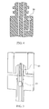
- a cylinder 59 extends into a mating opening in the lower surface of the head when pressure builds up in the gas line. It is intended that this locking structure may be used in combination with either embodiment of control means described above and shown in Figures 2 and 3 .
- Figure 5 shows an alternative interface embodiment of a droplet jet system in which a head portion 62 includes two opposing elastic members 63, 64 extending from the outer surface thereof.
- the lower surface 66 of head 62 is configured to fit with the upper surface 68 of handle portion 70.
- a fluid-tight relationship is created between the head and handle by O ring 72.
- only one supply line 74 is illustrated in the head and handle; however, it should be understood that the head and handle each have both gas and liquid lines.
- the outer surface 69 of elastic members 63, 64 include protrusions 76 which mate with matching cavities 78 in the inner surface of wall 79 of handle 70.
- the user pinches the elastic members inwardly, removing protrusions 76 from mating cavities 78, permitting the head to be lifted easily away from the handle.
- a new head can be simply positioned on the handle by pushing the head down onto the handle, forcing the elastic members inwardly, until the protrusions 76 come into registry with cavities 78, at which point the members 63, 64 spring outwardly, with protrusions 76 mating with cavities 78, locking the head to the handle.
- the fluid control arrangements of either Figure 2 or Figure 3 could equally be implemented in the alternative interface embodiment of Figure 5 .
- Figure 6 shows yet another alternative interface arrangement, involving a head portion 82, a handle portion 84 and an O ring seal 86.
- a plurality of elastic leg members 90 are positioned in a cavity 92, spaced around the periphery of the upper surface of the handle, with a ring member 94 threaded onto an exterior portion 95 of the upper surface of handle 84.
- An inner surface 96 of ring member 94 mates with elastic legs 90, such that as ring 94 is threaded down onto the handle, the upper portions of legs 90 are forced inwardly against a lower extending portion 93 of head portion 84, thus capturing and locking head 82 to the handle 84.
- FIGS 7A and 7B show another alternative interface arrangement.
- the system includes a handle 134 and a head 136.
- a T-shaped slot 138 In the top surface of handle 134 is a T-shaped slot 138, at the end of which is a connector block 140 with two openings 141, 143 therein which connect to the gas and liquid supply lines in the handle.
- a pin member 142 extends upwardly in the T-shaped slot 138, spring-loaded in the raised position, as shown in Figure 11A.
- the lower surface 144 of head 136 is configured to mate with the T-shaped slot 138 and also includes extending connectors 146 and 148 which are configured to mate in a fluid-tight relationship with the openings 141, 143 in the connector block 140.
- Pin member 142 in operation locks the head to the handle, as the head portion is slid into the T shaped slot, mating with connector block 140.
- button 150 is operated downwardly, moving pin 142 downwardly out of engagement with the head, permitting the head to be slid off and away from the handle.
- Figures 8A and 8B show a variation of the embodiment of Figures 7A and 7B .
- This embodiment includes a handle portion 154 and a head portion 156.
- the head portion engages the handle portion by a T-shaped slot 158 in the upper surface of handle 154 and a mating portion in the lower surface of head 156.
- Liquid and gas lines extend upwardly in the handle, terminating at surface 159 of the T-shaped slot with flexible annular seal elements 161.
- Flexible seal elements 161 are designed such that as head 156 is moved onto handle 154, the inner portions of the seal elements lift up, sealing against the edge of liquid and gas lines in the head which are in registry with the liquid and gas lines in the handle.
- Figures 9A and 9B show a further variation of the arrangements of Figures 7A , 7B and 8A and 8B.
- Figures 9A , 9B include a handle 162 and a head 164.
- Handle 162 has a T shaped slot 166 in the upper surface thereof, and two spring-loaded connectors 168 which extend upwardly above the surface 167 of T shaped slot 166 in their unloaded condition.
- the lower edges 168a of the connectors, located within the handle are secured to flexible fluid and gas lines 169 (one is hidden), as shown in Figure 13B.
- a button 170 extends from the connectors 168 to the outer surface of handle 162.
- the head 164 includes liquid and gas lines 165 (only one is shown) which open onto a lower surface 172 of head 164 and receive connectors 168.
- head 164 is slid onto the handle, with the lower surface 172 of the head being configured to force the spring-loaded connectors 168 downwardly against their spring bias until the head is fully onto the handle, where the connectors 168 are in registry with lines 165 in the head, at which point the connectors 168 spring back under the action of spring 171 to a fluid-tight connection with lines 165.
- button 170 is pushed downwardly, releasing the connectors 168 from the corresponding lines 165 in the head 164, and the head is slid away from the handle.
- FIGS 10A and 10B show a further variation involving a handle 174 with a T-shaped slot 178 in the upper surface thereof and a head portion 176 having a matching lower surface for engagement therewith.
- a connector block 180 which has openings 182 therein which connect with the liquid and gas lines in the handle.
- the head 176 includes a spring-loaded tube 184 within which are liquid and gas lines which terminate in fluid and gas connectors 186, which mate with openings 182 in the connector block 180 in a fluid-tight relationship when the head is connected to the handle.
- tube 184 is pulled upwardly, such that a bulbous portion 188 at the bottom of tube 184 is retracted fully into the head.
- the head is then slid fully onto the handle, and the tube 184 released, with bulb portion 188 then mating with a matching cavity 190 in the top surface of the handle, locking the head onto the handle.
- the tube 184 is raised, and the head is then slid away from the handle.
- a head/handle interface structure for a gas-assisted droplet jet system for cleaning teeth having a number of different embodiments has been shown and described.
- a single action by the user in connecting/disconnecting the head from the handle results in disconnecting both the gas and liquid lines between the head and the handle portions of the droplet jet system and a valve control means closes the respective fluid supply lines when the head is disconnected from the handle.
Landscapes
- Health & Medical Sciences (AREA)
- Dentistry (AREA)
- Epidemiology (AREA)
- Life Sciences & Earth Sciences (AREA)
- Animal Behavior & Ethology (AREA)
- General Health & Medical Sciences (AREA)
- Public Health (AREA)
- Veterinary Medicine (AREA)
- Quick-Acting Or Multi-Walled Pipe Joints (AREA)
- Nozzles (AREA)
- Brushes (AREA)
Abstract
A droplet jet teeth cleaning system comprising a handle portion, a head portion and an interface structure for connecting the handle portion to the head portion. The handle portion includes separate supply lines for liquid and gas and the head portion has separate supply lines for liquid and gas. The handle portion liquid and gas supply lines, respectively, are arranged to align only with the head portion liquid and gas supply lines when the head portion is operatively positioned on the handle portion. The system also includes a sealing interface arrangement for sealing the head portion gas line to the handle portion gas line and the head portion liquid line to the handle portion liquid line when the head portion is operatively positioned on the handle portion. The system includes control means for preventing fluid from escaping from the supply lines in the handle portion when the head portion is removed from the handle portion.
Description
- This invention relates generally to gas-assisted droplet jet systems for cleaning teeth, which include separate supply lines for the gas and the droplet liquid, and more specifically concerns an interface structure for removably connecting the head assembly of the system to the handle assembly.
- A droplet jet system for cleaning teeth is described in International Publication No.
WO2005070324 . That system produces a spray of small liquid droplets which are accelerated by a gas flow in a head portion of the system, for cleaning the frontal and interproximal areas of a user's teeth. The system includes a replaceable head portion relative to a permanent handle portion for supply and control of separate gas and liquid lines. - A droplet jet system for cleaning teeth is also disclosed in
US 4,531,913 and comprising a nozzle portion detachably mounted to a syringe body and including a connecting portion which comprises a tube joint to secure the nozzle portion to the syringe body. - However, there are several important considerations involving the interface for a replaceable head. The interface must include a reliable, effective seal between the gas and liquid lines, respectively, in the head and handle portions. The interface must be structured so that by a single action, both gas and liquid lines are connected/disconnected.
- Accordingly, it is desirable to have an interface which meets at least one of the above-desired structural considerations.
- Accordingly, the invention includes a droplet jet teeth cleaning system comprising a handle portion, a head portion and an interface structure for connecting the handle portion to the head portion, the handle portion containing a source of fluid from which droplets may be produced in the head portion and a source of gas for accelerating the resulting droplets to a desired velocity, including separate supply lines for liquid and gas in the handle portion; the head portion having separate supply lines for liquid and gas and an assembly for accelerating the liquid droplets out of the head portion using gas from the gas supply line therein, wherein the handle portion liquid and gas supply lines, respectively, are arranged to align only with the head portion liquid and gas supply lines when the head portion is operatively positioned on the handle portion; a sealing interface arrangement for sealing the head portion gas line to the handle portion gas line and the head portion liquid line to the handle portion liquid line when the head portion is operatively positioned on the handle portion, wherein the system includes control means for preventing fluid from escaping from the supply lines in the handle portion when the head portion is removed from the handle portion.
- The control means may be provided in the handle portion. The control means may include valves within the supply lines. The control means may comprise a valve which is closed when the head is detached from the handle, but which is actuated to open when the head is secured to the handle. The control means may include an electrical switch and mechanical shutoff valves for the supply lines. The control means may include a pin/ball assembly for blocking the supply lines in the handle portion when the head portion is removed from the handle portion.
- The interface structure may comprise a T-shaped slot in either the head portion or the handle portion, and a correspondingly shaped a mating portion on the other of the head portion and the handle portion for locking and unlocking the head portion to the handle portion.
- The upper surface of the handle portion may include a T shaped slot and the lower surface of the head portion may include a mating portion for locking and unlocking the head portion to the handle portion.
- The handle portion may include a connector block at the rear of the T shaped slot, having openings therein which connect to the gas and fluid lines in the handle portion, and the head portion may include mating connector elements which fit into the openings in the connector block in a fluid-tight relationship when the head is operatively positioned onto the handle, the mating connector elements being in fluid connection with the gas and liquid lines in the head portion.
- The system may include a spring-loaded retractable pin member for holding the head portion onto the handle portion, and for preventing the head portion from being removed when the pin is in its nonretracted position.
- The interface structure between the head and the handle may comprise resilient locking means configured to releaseably lock the head to the handle.
- The handle portion may include spring-loaded, retractable connectors which extend upwardly into the T shaped slot and mate with corresponding connections in the head portion in a fluid-tight relationship when the head is operatively positioned on the handle, and the system may further include a control member which when operated moves the retractable connectors downwardly away from engagement with the corresponding connectors on the head portion, permitting the head portion to be removed from or inserted on the handle portion.
- The head portion may have elastic ears extending upwardly from a lower portion thereof, wherein in an inward position of the elastic ears, the head portion may be moved onto and away from the handle portion, and wherein in a spread position of the elastic ears, projections on an exterior surface of the elastic member may engage corresponding slots in an upper portion of the handle to lock the head portion to the handle portion.
- The system may include a plurality of elastic legs positioned in the upper surface of the handle portion and extending upwardly thereof and a ring assembly which is threadably mounted on the handle portion, such that when the ring assembly is turned in the direction, upper portions of the elastic legs are forced against a lower part of a head portion which is positioned on the handle portion, thereby locking the head portion to the handle portion, and such that when the ring assembly is turned in an opposing direction, the upper portions of the elastic member are released from contact with the head portion, permitting the head portion to be removed from the handle portion.
- The gas and liquid lines may be physically separate from and independent of each other in both the handle and the head portions.
-
Figures 1A and1B show an exploded view and a partial cross-sectional view of a handle and a head portion of a droplet jet system and an interface structure for connecting the head portion to the handle portion; -
Figure 2 is a simplified diagram showing a valve and switch arrangement of an interface structure of a first embodiment of the invention for shutting off the gas and liquid supply lines in the handle when the head is removed from the handle; -
Figure 3 is a cross-sectional diagram showing a ball and pin arrangement of an interface structure of a second embodiment of the invention for shutting off the gas and liquid supply lines when the head is removed from the handle; -
Figure 4 is a diagram showing a system for locking the head to the handle when the system is pressurized; -
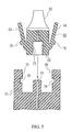
Figure 5 is a cross-sectional diagram showing another embodiment of an interface structure; -
Figure 6 is a cross-sectional diagram showing another embodiment of an interface structure; -
Figures 7A and7B are schematic and cross-sectional views, respectively, of another embodiment of an interface structure;. -
Figures 8A and8B are schematic and cross-sectional views, respectively, of yet another embodiment of an interface structure; -
Figures 9A and9B are schematic and cross-sectional views, respectively, of another embodiment of an interface structure; and -
Figures 10A and10B are schematic and cross-sectional views, respectively, of another embodiment of an interface structure. - As discussed briefly above, and in International Publication No.
WO2005070324 , which is owned by the assignee of the present invention and the contents of which are hereby incorporated by reference, a system for producing a spray of fine liquid droplets by means of a separate supply of pressurized gas, such as air, is known. With such a structure, it is advantageous that a head portion of the article, containing the liquid droplet-generating assembly and the droplet-accelerating assembly, using pressurized gas, accelerate the liquid droplets to advanced speed, and be removable from the handle portion, which contains the liquid and gas sources and the control elements for the system, including the on/off control, as well as any user interface structure. - A physical head/handle interface structure is necessary to enable the head portion to be conveniently and reliably removable from the handle portion and for a new head to be inserted. It is important that the interface structure be arranged so that the head can be positioned on the handle portion in only one orientation, so that the gas line in the handle is always connected to the gas line in the head and the liquid line in the handle is always connected to the liquid line in the head. Further, the arrangement must provide an adequate seal between the respective lines in the head and the handle, and must be simple and safe to use, as well as cost-effective. A single action must produce a reliable connect/disconnect for both lines.
- One embodiment of such a structure is shown in
Figures 1A and1B . The droplet jet system, shown generally at 10, includes an internal portion of ahandle 12 which at the top end includes two separate supply lines, oneline 14 for gas and the other line 16 for liquid. As disclosed in the '324 publication, the gas, typically air, is used to accelerate the liquid droplets to the desired speed, which is in the range of 30 70 meters per second in the embodiment described, although the interface structure described herein is not limited to such a droplet velocity. - The droplet jet system 10 also includes a
head portion 18 which contains a droplet-generating assembly and droplet acceleration assembly (not specifically shown). The accelerated droplets are directed into the mouth of the user for cleaning of his/her teeth. The upper surface 15 of thehandle portion 12 and thelower surface 17 of thehead portion 18 are configured so that they fit snugly together. In the embodiment shown, for each of the gas and liquid connections, respectively, referring toFigure 1B , the lower surface of the head portion has a donut-like protrusion 20 which fits into amating cavity 21 in the upper surface 15 of the handle portion.O ring seals 22 are positioned betweenprotrusion 20 and awall defining cavity 21, providing a fluid-tight connection between the two. - The gas and
liquid supply lines 14 and 16 in thehandle 12 are configured to be in registry with mating gas andliquid supply lines head portion 18. The respective free ends of the supply lines are configured such that the gas supply line from the handle can only be in registry with and connect with the gas supply line in the head, with the same being true for the liquid supply lines in the handle and head. The liquid supply line in the head may include a filter 34 to trap impurities in the liquid. - The
head 18 is locked to thehandle 12 by a tallcircular ring 36, which is threaded onto amating portion 38 of the upper surface 15 of the handle. Thehead portion 18 extends through opening 39 in thering 36. - To remove
head 18 fromhandle 12,ring 36 is unthreaded from the handle, and the head is then simply lifted away from the handle, with the donut protrusion of the head disengaging from the cavity in the upper surface of the handle. Conversely, a new head is first positioned onto the original handle portion and then thering 36 is threaded sufficiently to lock or tighten the head onto the handle. The arrangement ofFigures 1A and1B provides a reliable and convenient single-action connection (one action connects/disconnects both gas and liquid) between the handle and the head, as well as being safe, fluid-tight and cost-effective. - The head/handle interface includes a valve and control switch arrangement, by which the liquid and gas are both shut off in the handle when the head portion is removed, in order to prevent leakage or any spray from the lines in the handle portion during that time.
Figure 2 shows one embodiment of such a control valve arrangement which may be incorporated into the head/handle interface of the droplet jet system ofFigures 1A and1B . When the head has separated from the handle,switches 57 activatevalves 58, which close off the liquid and the gas lines. Each switch could be either electrical or mechanical in operation. It will be appreciated that the head/handle interface structure shown inFigure 2 is shown schematically only for simplicity of illustration, and is not exactly the same as that shown inFigure 1 . However, the features of the control valve arrangement shown inFigure 2 are nevertheless implementable with the device shown inFigures 1A and1B . -
Figure 3 shows an alternative embodiment to the switch/valve shutoff arrangement shown inFigure 2 , and comprises a ball and pin assembly, in which apin 60, connected to the head, moves aball 61, present in the handle, to permit flow in a line when the head is positioned onto the handle. A ball/pin combination is required for each line. When the head is removed, the respective balls move by action of the liquid and the gas to cut off the flows thereof. Other control mechanisms are possible as well. - Both the fluid control arrangements of
Figures 2 and3 provide a valve which is closed when the head is detached from the handle, but which is actuated, either mechanically or electrically, to open when the head is secured to the handle. -
Figure 4 is an arrangement which shows a locking structure to prevent the head from being removed from the handle when the system is pressurized. Acylinder 59 extends into a mating opening in the lower surface of the head when pressure builds up in the gas line. It is intended that this locking structure may be used in combination with either embodiment of control means described above and shown inFigures 2 and3 . -
Figure 5 shows an alternative interface embodiment of a droplet jet system in which ahead portion 62 includes two opposingelastic members lower surface 66 ofhead 62 is configured to fit with theupper surface 68 ofhandle portion 70. A fluid-tight relationship is created between the head and handle byO ring 72. For simplicity, only onesupply line 74 is illustrated in the head and handle; however, it should be understood that the head and handle each have both gas and liquid lines. - The
outer surface 69 ofelastic members protrusions 76 which mate with matchingcavities 78 in the inner surface ofwall 79 ofhandle 70. When the head is to be removed from the handle, the user pinches the elastic members inwardly, removingprotrusions 76 frommating cavities 78, permitting the head to be lifted easily away from the handle. A new head can be simply positioned on the handle by pushing the head down onto the handle, forcing the elastic members inwardly, until theprotrusions 76 come into registry withcavities 78, at which point themembers protrusions 76 mating withcavities 78, locking the head to the handle. It will be appreciated that the fluid control arrangements of eitherFigure 2 orFigure 3 could equally be implemented in the alternative interface embodiment ofFigure 5 . -
Figure 6 shows yet another alternative interface arrangement, involving ahead portion 82, ahandle portion 84 and anO ring seal 86. Again, for simplicity of illustration, only one handle/head fluid line 88 is illustrated. A plurality ofelastic leg members 90 are positioned in acavity 92, spaced around the periphery of the upper surface of the handle, with aring member 94 threaded onto anexterior portion 95 of the upper surface ofhandle 84. Aninner surface 96 ofring member 94 mates withelastic legs 90, such that asring 94 is threaded down onto the handle, the upper portions oflegs 90 are forced inwardly against a lower extendingportion 93 ofhead portion 84, thus capturing and lockinghead 82 to thehandle 84. When the head is to be removed,ring 94 is simply unscrewed, which releaseslegs 90, permittinghead 82 to be simply pulled away from thehandle 84. Again, it is intended within the scope of the invention that the fluid control arrangements of eitherFigure 2 orFigure 3 could equally be implemented in the alternative interface embodiment ofFigure 6 . Also, both embodiments shown inFigures 5 and6 include variations of resilient locking members configured to lock the head to the handle. -
Figures 7A and7B show another alternative interface arrangement. The system includes ahandle 134 and ahead 136. In the top surface ofhandle 134 is a T-shapedslot 138, at the end of which is aconnector block 140 with twoopenings pin member 142 extends upwardly in the T-shapedslot 138, spring-loaded in the raised position, as shown in Figure 11A. Thelower surface 144 ofhead 136 is configured to mate with the T-shapedslot 138 and also includes extendingconnectors openings connector block 140. -
Pin member 142 in operation locks the head to the handle, as the head portion is slid into the T shaped slot, mating withconnector block 140. When the head is to be removed,button 150 is operated downwardly, movingpin 142 downwardly out of engagement with the head, permitting the head to be slid off and away from the handle. -
Figures 8A and8B show a variation of the embodiment ofFigures 7A and7B . This embodiment includes ahandle portion 154 and ahead portion 156. The head portion engages the handle portion by a T-shapedslot 158 in the upper surface ofhandle 154 and a mating portion in the lower surface ofhead 156. Liquid and gas lines extend upwardly in the handle, terminating atsurface 159 of the T-shaped slot with flexibleannular seal elements 161.Flexible seal elements 161 are designed such that ashead 156 is moved ontohandle 154, the inner portions of the seal elements lift up, sealing against the edge of liquid and gas lines in the head which are in registry with the liquid and gas lines in the handle. -
Figures 9A and9B show a further variation of the arrangements ofFigures 7A ,7B and 8A and8B. Figures 9A ,9B include ahandle 162 and ahead 164. Handle 162 has a T shapedslot 166 in the upper surface thereof, and two spring-loadedconnectors 168 which extend upwardly above thesurface 167 of T shapedslot 166 in their unloaded condition. Thelower edges 168a of the connectors, located within the handle, are secured to flexible fluid and gas lines 169 (one is hidden), as shown in Figure 13B. Abutton 170 extends from theconnectors 168 to the outer surface ofhandle 162. Thehead 164 includes liquid and gas lines 165 (only one is shown) which open onto alower surface 172 ofhead 164 and receiveconnectors 168. - In use,
head 164 is slid onto the handle, with thelower surface 172 of the head being configured to force the spring-loadedconnectors 168 downwardly against their spring bias until the head is fully onto the handle, where theconnectors 168 are in registry withlines 165 in the head, at which point theconnectors 168 spring back under the action of spring 171 to a fluid-tight connection withlines 165. To release/remove the head from the handle,button 170 is pushed downwardly, releasing theconnectors 168 from the correspondinglines 165 in thehead 164, and the head is slid away from the handle. -
Figures 10A and10B show a further variation involving ahandle 174 with a T-shapedslot 178 in the upper surface thereof and ahead portion 176 having a matching lower surface for engagement therewith. At the rear of T-shapedslot 178 is aconnector block 180 which hasopenings 182 therein which connect with the liquid and gas lines in the handle. - The
head 176 includes a spring-loadedtube 184 within which are liquid and gas lines which terminate in fluid andgas connectors 186, which mate withopenings 182 in theconnector block 180 in a fluid-tight relationship when the head is connected to the handle. To engage the head to the handle,tube 184 is pulled upwardly, such that abulbous portion 188 at the bottom oftube 184 is retracted fully into the head. The head is then slid fully onto the handle, and thetube 184 released, withbulb portion 188 then mating with amatching cavity 190 in the top surface of the handle, locking the head onto the handle. To release/remove the head, thetube 184 is raised, and the head is then slid away from the handle. It will be appreciated that, and it is intended within the scope of the invention that, the fluid control arrangements of eitherFigure 2 orFigure 3 could equally be implemented in the alternative interface embodiments ofFigures 7A - 10B . - Accordingly, a head/handle interface structure for a gas-assisted droplet jet system for cleaning teeth having a number of different embodiments has been shown and described. In all of the embodiments, a single action by the user in connecting/disconnecting the head from the handle results in disconnecting both the gas and liquid lines between the head and the handle portions of the droplet jet system and a valve control means closes the respective fluid supply lines when the head is disconnected from the handle.
- Although embodiments of the invention have been disclosed for purposes of illustration, it should be understood that various changes, modifications and substitutions may be incorporated in the embodiment without departing from the scope of the invention which is defined by the claims which follow. It will be appreciated that the embodiments described above with an interface structure comprising a T-shaped slot in the handle portion and a corresponding mating component on the head portion may be reversed, such that the T-shaped slot is formed on the head and the corresponding mating portion is formed on the handle.
Claims (12)
- A droplet jet teeth cleaning system comprising a handle portion (12, 70, 84, 134, 154, 162, 174), a head portion (18, 62, 82, 136, 156, 164, 176) and an interface structure for connecting the handle portion to the head portion, the handle portion containing a source of fluid from which droplets may be produced in the head portion and a source of gas for accelerating the resulting droplets to a desired velocity, including separate supply lines (14, 16, 74, 88, 169) for liquid and gas in the handle portion; the head portion having separate supply lines (28, 30, 88, 165) for liquid and gas and an assembly for accelerating the liquid droplets out of the head portion using gas from the gas supply line therein, wherein the handle portion liquid and gas supply lines, respectively, are arranged to align only with the head portion liquid and gas supply lines when the head portion is operatively positioned on the handle portion; a sealing interface arrangement (15,17, 20, 21, 22) for sealing the head portion gas line to the handle portion gas line and the head portion liquid line to the handle portion liquid line when the head portion is operatively positioned on the handle portion, wherein the system includes control means (57, 58, 60, 61) for preventing fluid from escaping from the supply lines in the handle portion when the head portion is removed from the handle portion.
- The system of claim 1 wherein the control means (57, 58, 60, 61) comprises a valve which is closed when the head is detached from the handle, but which is actuated to open when the head is secured to the handle.
- The system of claim 1 or claim 2, wherein the control means includes an electrical switch (57) and mechanical shutoff valves (58) for the supply lines (14, 16, 74, 88, 169).
- The system of claim 1 or claim 2, wherein the control means includes a pin/ball assembly (60, 61) for blocking the supply lines (14, 16, 74, 88, 169) in the handle portion (12, 70, 84, 134, 154, 162, 174) when the head portion (18, 62, 82, 136, 156, 164, 176) is removed from the handle portion.
- The system of any preceding claim, wherein the interface structure comprises a T-shaped slot (138, 158, 166, 178) in either the head portion or the handle portion, and a correspondingly shaped a mating portion on the other of the head portion and the handle portion for locking and unlocking the head portion to the handle portion.
- The system of claim 5, wherein the upper surface of the handle portion (134, 154, 162, 174) includes a T shaped slot (138, 158, 166, 178) and the lower surface (144, 172) of the head portion (136, 156, 164, 176) includes a mating portion for locking and unlocking the head portion to the handle portion.
- The system of claim 6, wherein the handle portion includes a connector block (140, 180), at the rear of the T shaped slot, having openings (141, 143, 182) therein which connect to the gas and fluid lines in the handle portion, and wherein the head portion includes mating connector elements (146, 148, 186) which fit into the openings in the connector block in a fluid-tight relationship when the head is operatively positioned onto the handle, the mating connector elements being in fluid connection with the gas and liquid lines in the head portion.
- The system of claim 7, including a spring-loaded retractable pin member (142) for holding the head portion onto the handle portion, and for preventing the head portion from being removed when the pin is in its nonretracted position.
- The system of claim 6, wherein the handle portion includes spring-loaded, retractable connectors (168) which extend upwardly into the T shaped slot (167) and mate with corresponding connections in the head portion in a fluid-tight relationship when the head is operatively positioned on the handle, the system further including a control member (170) which when operated moves the retractable connectors downwardly away from engagement with the corresponding connectors on the head portion, permitting the head portion to be removed from or inserted on the handle portion.
- The system of any of claim 1 to 4, wherein the head portion (62) has elastic ears (63, 64) extending upwardly from a lower portion thereof, wherein in an inward position of the elastic ears, the head portion may be moved onto and away from the handle portion (70), and wherein in a spread position of the elastic ears, projections (76) on an exterior surface of the elastic member engage corresponding slots (78) in an upper portion of the handle to lock the head portion to the handle portion.
- The system of any of claims 1 to 4, including a plurality of elastic legs (90) positioned in the upper surface of the handle portion (84) and extending upwardly thereof and a ring assembly (94) which is threadably mounted on the handle portion, such that when the ring assembly is turned in the direction, upper portions of the elastic legs are forced against a lower part (93) of a head portion which is positioned on the handle portion, thereby locking the head portion to the handle portion, and such that when the ring assembly is turned in an opposing direction, the upper portions of the elastic member are released from contact with the head portion, permitting the head portion to be removed from the handle portion.
- The system of any preceding claim, wherein the gas and liquid lines are physically separate from and independent of each other in both the handle and the head portions.
Applications Claiming Priority (2)
| Application Number | Priority Date | Filing Date | Title |
|---|---|---|---|
| US81438106P | 2006-06-15 | 2006-06-15 | |
| EP07766712.9A EP2032069B1 (en) | 2006-06-15 | 2007-06-12 | Droplet jet system for cleaning teeth |
Related Parent Applications (2)
| Application Number | Title | Priority Date | Filing Date |
|---|---|---|---|
| EP07766712.9 Division | 2007-06-12 | ||
| EP07766712.9A Division-Into EP2032069B1 (en) | 2006-06-15 | 2007-06-12 | Droplet jet system for cleaning teeth |
Publications (1)
| Publication Number | Publication Date |
|---|---|
| EP2656814A2 true EP2656814A2 (en) | 2013-10-30 |
Family
ID=38617469
Family Applications (2)
| Application Number | Title | Priority Date | Filing Date |
|---|---|---|---|
| EP07766712.9A Not-in-force EP2032069B1 (en) | 2006-06-15 | 2007-06-12 | Droplet jet system for cleaning teeth |
| EP13177611.4A Withdrawn EP2656814A2 (en) | 2006-06-15 | 2007-06-12 | A droplet jet teeth cleaning system |
Family Applications Before (1)
| Application Number | Title | Priority Date | Filing Date |
|---|---|---|---|
| EP07766712.9A Not-in-force EP2032069B1 (en) | 2006-06-15 | 2007-06-12 | Droplet jet system for cleaning teeth |
Country Status (5)
| Country | Link |
|---|---|
| US (1) | US8210846B2 (en) |
| EP (2) | EP2032069B1 (en) |
| JP (1) | JP5543202B2 (en) |
| CN (1) | CN101466328B (en) |
| WO (1) | WO2007144821A2 (en) |
Families Citing this family (24)
| Publication number | Priority date | Publication date | Assignee | Title |
|---|---|---|---|---|
| BRPI0821233A2 (en) * | 2007-12-18 | 2015-06-16 | Koninkl Philips Electronics Nv | Protective system for a compressed gas oral cleaning appliance |
| CN103269654B (en) | 2010-12-20 | 2016-09-21 | 皇家飞利浦电子股份有限公司 | Brush heads with wedge and spring handle interface for electric toothbrushes |
| JP2014513586A (en) * | 2011-02-28 | 2014-06-05 | コーニンクレッカ フィリップス エヌ ヴェ | Interface structure for liquid / air burst |
| JP5784975B2 (en) * | 2011-05-13 | 2015-09-24 | 株式会社ナカニシ | Dental handpiece |
| FR2983398B1 (en) * | 2011-12-05 | 2013-12-06 | Prod Dentaires Pierre Rolland | CANNULA AND ADAPTER FOR MULTIFUNCTION SYRINGE |
| CN103371875B (en) * | 2012-04-16 | 2016-12-14 | 李斌 | A kind of combination type mouth washes instrument of band pre-washing function |
| EP2742897A1 (en) | 2012-12-17 | 2014-06-18 | 3M Innovative Properties Company | Nozzle head, hand piece and powder jet device for applying a dental material |
| WO2014099490A2 (en) * | 2012-12-17 | 2014-06-26 | 3M Innovative Properties Company | Device for dispensing a dental material with locking mechanism |
| EP2742898A1 (en) | 2012-12-17 | 2014-06-18 | 3M Innovative Properties Company | Powder jet device for dispensing a dental material |
| RU2015144022A (en) * | 2013-03-15 | 2017-04-21 | Конинклейке Филипс Н.В. | ORAL CARE DEVICE USING JET TYPE FLOW AND MECHANICAL ACTION |
| KR101646053B1 (en) * | 2015-02-16 | 2016-08-08 | 이승민 | Teeth cleaning device having water flow channel |
| RU2017143646A (en) | 2015-05-15 | 2019-06-17 | Дайсон Текнолоджи Лимитед | CLEANING DEVICE |
| GB2538301B (en) * | 2015-05-15 | 2017-09-20 | Dyson Technology Ltd | Cleaning appliance |
| USD769101S1 (en) * | 2015-08-18 | 2016-10-18 | Blue Rhino Global Sourcing, Inc. | Locking mechanism for a handle |
| CN106667604A (en) * | 2015-11-06 | 2017-05-17 | 郭累 | 3d visualization toothbrush |
| US10524888B1 (en) * | 2016-09-30 | 2020-01-07 | Vincent Losack | Oral hygiene system |
| CN107836810A (en) * | 2017-10-20 | 2018-03-27 | 广东罗曼智能科技股份有限公司 | An electric cleaning brush with various cleaning methods |
| CN109806018B (en) * | 2019-01-10 | 2021-04-20 | 上海携福电器有限公司 | Nozzle for tooth rinsing device and tooth rinsing device thereof |
| CN109528332A (en) * | 2019-01-10 | 2019-03-29 | 上海携福电器有限公司 | Tooth flusher |
| CN211156401U (en) * | 2019-09-19 | 2020-08-04 | 壹潇科技(绍兴)有限公司 | Stably-operating tooth washing device |
| USD968891S1 (en) | 2021-03-18 | 2022-11-08 | Mr. Bar-B-Q Products Llc | Grilling basket |
| GR1010587B (en) * | 2021-09-29 | 2023-12-18 | Implantsci Ltd., | Dental irrigator and method of use |
| USD1016554S1 (en) | 2021-10-08 | 2024-03-05 | Mr. Bar-B-Q Products Llc | Utensil handle |
| USD998405S1 (en) | 2021-12-01 | 2023-09-12 | Mr. Bar-B-Q Products Llc | Tray holder |
Citations (2)
| Publication number | Priority date | Publication date | Assignee | Title |
|---|---|---|---|---|
| US4531913A (en) | 1983-05-26 | 1985-07-30 | Takara Nakajima Co., Ltd. | Dental syringe |
| WO2005070324A2 (en) | 2004-01-20 | 2005-08-04 | Koninklijke Philips Electronics, N.V. | Droplet jet system for cleaning teeth |
Family Cites Families (16)
| Publication number | Priority date | Publication date | Assignee | Title |
|---|---|---|---|---|
| JPS5656987U (en) * | 1979-10-09 | 1981-05-16 | ||
| GB2213732B (en) | 1988-01-14 | 1991-11-13 | Segal Alan J | Dental apparatus |
| JPH0627917Y2 (en) * | 1988-07-28 | 1994-07-27 | 株式会社ハーマン | Pipe fitting and pipe connection device |
| US5192206A (en) | 1988-09-06 | 1993-03-09 | Warren Davis | Dental syringe tip and adaptor |
| US5489205A (en) * | 1988-09-06 | 1996-02-06 | Davis; Warren | Syringe tip locking assembly |
| ATE132728T1 (en) * | 1989-01-16 | 1996-01-15 | Segal Alan J | DENTAL DEVICE |
| US4991249A (en) * | 1989-02-09 | 1991-02-12 | Suroff Leonard W | Ultrasonic toothbrush |
| US5203698A (en) * | 1991-04-25 | 1993-04-20 | Blake Thomas S | Wet foam sandblaster |
| US5716210A (en) * | 1993-12-29 | 1998-02-10 | Dentsply Research & Development Corp. | Disposable filter for dental handpiece |
| JPH07317997A (en) * | 1994-05-23 | 1995-12-08 | Kanto Auto Works Ltd | Gas filling chuck |
| JP3081248B2 (en) * | 1994-10-04 | 2000-08-28 | 耕一 岡野 | Periodontal pocket cleaning device |
| US5772433A (en) | 1995-04-18 | 1998-06-30 | Esrock; Bernard S. | Disposable dental syringe tip |
| US5593304A (en) * | 1995-06-16 | 1997-01-14 | Ram; Zeev | Dental apparatus including multiple-use electrically-oscillated handpiece |
| US5765759C1 (en) * | 1995-11-27 | 2001-11-06 | Danville Engineering | Removable nozzle for a sandblaster handpiece |
| DE19755826C1 (en) * | 1997-12-16 | 1999-05-20 | Raymond A & Cie | Releasable connector for pressure hoses |
| TR200003616T2 (en) | 1998-03-19 | 2001-04-20 | Warren Davis | Illuminated syringe tip and grip assembly. |
-
2007
- 2007-06-12 US US12/303,128 patent/US8210846B2/en not_active Expired - Fee Related
- 2007-06-12 JP JP2009514963A patent/JP5543202B2/en not_active Expired - Fee Related
- 2007-06-12 CN CN2007800220902A patent/CN101466328B/en not_active Expired - Fee Related
- 2007-06-12 EP EP07766712.9A patent/EP2032069B1/en not_active Not-in-force
- 2007-06-12 WO PCT/IB2007/052203 patent/WO2007144821A2/en not_active Ceased
- 2007-06-12 EP EP13177611.4A patent/EP2656814A2/en not_active Withdrawn
Patent Citations (2)
| Publication number | Priority date | Publication date | Assignee | Title |
|---|---|---|---|---|
| US4531913A (en) | 1983-05-26 | 1985-07-30 | Takara Nakajima Co., Ltd. | Dental syringe |
| WO2005070324A2 (en) | 2004-01-20 | 2005-08-04 | Koninklijke Philips Electronics, N.V. | Droplet jet system for cleaning teeth |
Also Published As
| Publication number | Publication date |
|---|---|
| WO2007144821A3 (en) | 2008-04-24 |
| CN101466328A (en) | 2009-06-24 |
| JP2009539542A (en) | 2009-11-19 |
| US8210846B2 (en) | 2012-07-03 |
| EP2032069B1 (en) | 2014-03-05 |
| JP5543202B2 (en) | 2014-07-09 |
| WO2007144821A2 (en) | 2007-12-21 |
| EP2032069A2 (en) | 2009-03-11 |
| US20090317758A1 (en) | 2009-12-24 |
| CN101466328B (en) | 2013-11-06 |
Similar Documents
| Publication | Publication Date | Title |
|---|---|---|
| EP2656814A2 (en) | A droplet jet teeth cleaning system | |
| US11179231B2 (en) | Oral irrigator handle for use with oral agent | |
| CN110062663B (en) | Gun and Nozzle Assembly Attachment | |
| EP1689472B1 (en) | Self-locking safety disposable syringe with needle protection after use | |
| TWI463089B (en) | A female coupling element and a quick coupling including such an element | |
| US5848893A (en) | Dental spray syringe | |
| US6283750B1 (en) | Method of connecting a syringe tip to a dental syringe hand piece | |
| EP1636090A2 (en) | High workload needle-free injection system | |
| JP2005007001A (en) | Liquid feeding apparatus of endoscope | |
| WO2003103752A1 (en) | Needle-free injection system | |
| US5713878A (en) | Hand tightenable high pressure connector | |
| WO2010005508A1 (en) | Quick change nozzle | |
| JPH07308381A (en) | Medical spray syringe | |
| US20100273127A1 (en) | Protective assembly for a compressed gas interproximal cleaner | |
| US10357345B2 (en) | Automatic filling mechanism and method for a hand-held oral cleaning device | |
| US8316897B2 (en) | Water gun assembly | |
| CN103877658A (en) | Detachable inspiratory relief valve | |
| KR20160102241A (en) | Sprayer | |
| JP3893488B2 (en) | Dental sandblast handpiece | |
| EP1043080A1 (en) | Ejection nozzle and handle assembly for a domestic high-pressure cleaner | |
| JP2001343093A (en) | Reverse flow prevention coupling | |
| CN220344878U (en) | Safety syringe assembly and safety syringe | |
| JP3516739B2 (en) | A kit equipped with a multi-cylinder mechanism for opening and injecting a powder drug capsule into a body cavity and a container for a gas for pumping | |
| US20240382991A1 (en) | Liquid dispenser | |
| CN209221209U (en) | Vaporizer |
Legal Events
| Date | Code | Title | Description |
|---|---|---|---|
| PUAI | Public reference made under article 153(3) epc to a published international application that has entered the european phase |
Free format text: ORIGINAL CODE: 0009012 |
|
| AC | Divisional application: reference to earlier application |
Ref document number: 2032069 Country of ref document: EP Kind code of ref document: P |
|
| AK | Designated contracting states |
Kind code of ref document: A2 Designated state(s): AT BE BG CH CY CZ DE DK EE ES FI FR GB GR HU IE IS IT LI LT LU LV MC MT NL PL PT RO SE SI SK TR |
|
| STAA | Information on the status of an ep patent application or granted ep patent |
Free format text: STATUS: THE APPLICATION HAS BEEN WITHDRAWN |
|
| 18W | Application withdrawn |
Effective date: 20141106 |