EP2656711A1 - Linkage component on an agricultural vehicle - Google Patents
Linkage component on an agricultural vehicle Download PDFInfo
- Publication number
- EP2656711A1 EP2656711A1 EP13158265.2A EP13158265A EP2656711A1 EP 2656711 A1 EP2656711 A1 EP 2656711A1 EP 13158265 A EP13158265 A EP 13158265A EP 2656711 A1 EP2656711 A1 EP 2656711A1
- Authority
- EP
- European Patent Office
- Prior art keywords
- mounting component
- fluid
- component
- tractor
- reservoir
- Prior art date
- Legal status (The legal status is an assumption and is not a legal conclusion. Google has not performed a legal analysis and makes no representation as to the accuracy of the status listed.)
- Withdrawn
Links
Images



Classifications
-
- B—PERFORMING OPERATIONS; TRANSPORTING
- B60—VEHICLES IN GENERAL
- B60D—VEHICLE CONNECTIONS
- B60D1/00—Traction couplings; Hitches; Draw-gear; Towing devices
- B60D1/24—Traction couplings; Hitches; Draw-gear; Towing devices characterised by arrangements for particular functions
-
- A—HUMAN NECESSITIES
- A01—AGRICULTURE; FORESTRY; ANIMAL HUSBANDRY; HUNTING; TRAPPING; FISHING
- A01B—SOIL WORKING IN AGRICULTURE OR FORESTRY; PARTS, DETAILS, OR ACCESSORIES OF AGRICULTURAL MACHINES OR IMPLEMENTS, IN GENERAL
- A01B59/00—Devices specially adapted for connection between animals or tractors and agricultural machines or implements
- A01B59/06—Devices specially adapted for connection between animals or tractors and agricultural machines or implements for machines mounted on tractors
-
- A—HUMAN NECESSITIES
- A01—AGRICULTURE; FORESTRY; ANIMAL HUSBANDRY; HUNTING; TRAPPING; FISHING
- A01B—SOIL WORKING IN AGRICULTURE OR FORESTRY; PARTS, DETAILS, OR ACCESSORIES OF AGRICULTURAL MACHINES OR IMPLEMENTS, IN GENERAL
- A01B59/00—Devices specially adapted for connection between animals or tractors and agricultural machines or implements
Definitions
- This invention relates to a mounting component for operating a linkage on an agricultural machine. More specifically, the invention relates to a mounting component for operating a front linkage on an agricultural tractor.
- a front linkage arrangement typically comprises a mounting component pivotably mounted to the tractor and having linkage mounts by means of which an implement may be mounted to the tractor.
- the mounting component can be moved by hydraulic cylinders to raise or lower the implement.
- a tractor requires various fluids in varying quantities to be carried on the tractor in fluid reserves. Hydraulic fluids, fuel, cleaning fluids and exhaust treatment fluids need to be carried. With the ever developing need for efficient tractors, space on a tractor is at a premium. Re-arranging components on a tractor to provide extra space for a further or larger component, such as a fluid reserve, is a time consuming and costly task.
- a canister At the front of a tractor, for example, a canister is used to collect hydraulic oil which leaks from the hydraulic couplings to a front-mounted implement.
- the installation of a canister on a tractor has space and cost implications.
- a mounting component for operating a front linkage on an agricultural vehicle, wherein said mounting component is a unitary (one-piece) body adapted to store fluids.
- the mounting component comprises a central cavity in which a fluid is stored.
- the mounting component is provided with at least one fluid inlet or outlet.
- the mounting component may be adapted to receive tubing. This way fluid can be delivered to, or from a desired component on the vehicle.
- the mounting component is an hydraulic oil reserve. More preferably, the mounting component is a leak oil reserve which collects oil leaking from the hydraulic couplings.
- the tractor does not therefore need a canister to store the leak oil thus saving money and space.
- the mounting component is provided with means for showing the volume of liquid stored in the mounting component. Therefore, if the cavity of the mounting component is full it can be emptied.
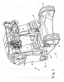
- Figure 1 shows a front linkage mounting component 1 mounted on the front of a tractor, shown generally at 2.
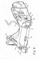
- the mounting component is a generally H-shaped cast metal component having a transverse body portion la linking side arms 1b extending forward and behind the main body.
- a through bore 3 At the rear end of each side arm is a through bore 3 to receive a pivot pin (not shown) which pin passes through corresponding bores in support arms 4 of the tractor frame to allow the mounting component 1 to pivot relative to the tractor 2 about axis X ( Fig. 1 ).
- a respective linkage mount 5 to which front linkage components enabling connection to an implement may be attached.
- a pair of hydraulic cylinders 6 are each pivotably attached at one end to the tractor 2 and at the other to the mounting component 1. When the cylinders are operated, the mounting component (and any implement mounted thereto) may be raised and lowered.
- the main body la of the component has a cavity 7 in which a fluid may be stored.
- the fluid for example may be hydraulic oil, pressurised air, or a cleaning fluid such as a windscreen cleanin fluid.
- the main body 1a is provided with at least one inlet 8 and one outlet 9 through which a fluid can enter, or exit, the cavity 7.
- the inlet 8 may instead be provided on a front, side, top or bottom part.
- a separate fluid reservoir 10 is housed within the cavity 7 to receive the fluid.
- This reservoir component is suitably formed of a pressure moulded plastics material (although other materials may be used) and, as shown by Figure 3 , can be simply extracted from the mounting component for maintenance or replacement. This is of particular benefit where it is desired to change the fluid received (for example from hydraulic oil to windscreen washer fluid) and it is necessary to avoid cross-contamination.
- the reservoir 10 is a generally cylindrical container extending the length of the transverse main body 1a to emerge with end faces coplanar with (or slightly proud of) the surfaces of the two side arms 1b.
- a part of the way along the axial length of the reservoir there is an inlet connection 8a which, when the reservoir is positioned within the cavity, aligns with the inlet opening 8 in the cast body of the mounting component to enable connection of an input line 11.
- the outer surface of the reservoir may be provided with one or more ridges or projections 12 which cooperate with the cast body of the mounting component such that the reservoir is a snap-fit within the component.
- Alternative arrangements having recessed portions on the reservoir surface cooperating with projections from the cast body are also possible.
- the wall thicknesses of the reservoir will need to be greater than shown in Figure 5 .
- a discharge plug 13 On one end face of the reservoir cylinder there is shown a discharge plug 13 by means of which the reservoir may be emptied without the reservoir needing to be removed from the mounting component.
- the discharge plug may be replaced by an outlet connection to a fluid conduit, or the arrangement of input and output may be reversed. Other variations in terms of the number and location of inputs and outputs to the reservoir are also contemplated.
- a set of hydraulic couplings 14 are shown. These are mounted to the front of the tractor and provide a supply of hydraulic oil to a mounted implement. Typically, any leakage from these couplings would be transported away from the couplings in tubing to a separate canister mounted to the tractor. With the present invention, the leakage oil can be transported by an inflow line 11, for example of transparent flexible plastic tubing, through inlet 8 into the reservoir 10 housed within the mounting component 1. By the use of a transparent tube extending generally upwardly from the reservoir, it can be seen by external inspection when the reservoir is full an requires draining.
- the cavity 7 could be divided into two or more fluid compartments, each suitably containing a respective reservoir, for holding two or more fluids.
- Each reservoir would be provided with an associated inlet/outlet.
Landscapes
- Life Sciences & Earth Sciences (AREA)
- Engineering & Computer Science (AREA)
- Mechanical Engineering (AREA)
- Zoology (AREA)
- Soil Sciences (AREA)
- Environmental Sciences (AREA)
- Transportation (AREA)
- Body Structure For Vehicles (AREA)
- Loading And Unloading Of Fuel Tanks Or Ships (AREA)
- Supply Devices, Intensifiers, Converters, And Telemotors (AREA)
Abstract
A mounting component forming an operational part of a front linkage on an agricultural vehicle, wherein said component is a unitary body adapted for storing at least one fluid.
Description
- This invention relates to a mounting component for operating a linkage on an agricultural machine. More specifically, the invention relates to a mounting component for operating a front linkage on an agricultural tractor.
- Agricultural tractors are typically provided with a three point linkage or hitch at the rear of the tractor to which an implement can be attached and, increasingly, such linkages are also being provided at the front of tractors. A front linkage arrangement typically comprises a mounting component pivotably mounted to the tractor and having linkage mounts by means of which an implement may be mounted to the tractor. The mounting component can be moved by hydraulic cylinders to raise or lower the implement.
- A tractor requires various fluids in varying quantities to be carried on the tractor in fluid reserves. Hydraulic fluids, fuel, cleaning fluids and exhaust treatment fluids need to be carried. With the ever developing need for efficient tractors, space on a tractor is at a premium. Re-arranging components on a tractor to provide extra space for a further or larger component, such as a fluid reserve, is a time consuming and costly task.
- At the front of a tractor, for example, a canister is used to collect hydraulic oil which leaks from the hydraulic couplings to a front-mounted implement. The installation of a canister on a tractor has space and cost implications.
- It is an object of the invention to overcome, or at least al leviate the problems associated with the storage of fluids on a tractor.
- According to the invention there is provided a mounting component for operating a front linkage on an agricultural vehicle, wherein said mounting component is a unitary (one-piece) body adapted to store fluids.
- Preferably, the mounting component comprises a central cavity in which a fluid is stored.
- More preferably, the mounting component is provided with at least one fluid inlet or outlet.
- The mounting component may be adapted to receive tubing. This way fluid can be delivered to, or from a desired component on the vehicle.
- Preferably, the mounting component is an hydraulic oil reserve. More preferably, the mounting component is a leak oil reserve which collects oil leaking from the hydraulic couplings.
- The tractor does not therefore need a canister to store the leak oil thus saving money and space.
- Preferably the mounting component is provided with means for showing the volume of liquid stored in the mounting component. Therefore, if the cavity of the mounting component is full it can be emptied.
- The invention will now be described, by way of example only with reference to the following drawings in which:
-
Figure 1 shows a perspective view of a front linkage mounting component in accordance with the invention attached to an agricultural tractor; -
Figure 2 shows the component ofFigure 1 demounted from the tractor; -
Figure 3 shows the demounted component ofFigure 2 with a cavity reservoir partially extracted; -
Figure 4 is a rear perspective view of the component ofFigure 2 ; and -
Figure 5 shows a cross sectional view along line A-A ofFigure 4 . -
Figure 1 shows a frontlinkage mounting component 1 mounted on the front of a tractor, shown generally at 2. As can be seen more clearly inFigure 2 , the mounting component is a generally H-shaped cast metal component having a transverse body portion la linking side arms 1b extending forward and behind the main body. At the rear end of each side arm is athrough bore 3 to receive a pivot pin (not shown) which pin passes through corresponding bores in support arms 4 of the tractor frame to allow themounting component 1 to pivot relative to thetractor 2 about axis X (Fig. 1 ). At the forward end of each side arm 1b there is arespective linkage mount 5 to which front linkage components enabling connection to an implement may be attached. - A pair of hydraulic cylinders 6 are each pivotably attached at one end to the
tractor 2 and at the other to themounting component 1. When the cylinders are operated, the mounting component (and any implement mounted thereto) may be raised and lowered. - The main body la of the component has a
cavity 7 in which a fluid may be stored. The fluid for example may be hydraulic oil, pressurised air, or a cleaning fluid such as a windscreen cleanin fluid. The main body 1a is provided with at least oneinlet 8 and oneoutlet 9 through which a fluid can enter, or exit, thecavity 7. Although shown on a rear part of the component, theinlet 8 may instead be provided on a front, side, top or bottom part. - In a preferred arrangement, a
separate fluid reservoir 10 is housed within thecavity 7 to receive the fluid. This reservoir component is suitably formed of a pressure moulded plastics material (although other materials may be used) and, as shown byFigure 3 , can be simply extracted from the mounting component for maintenance or replacement. This is of particular benefit where it is desired to change the fluid received (for example from hydraulic oil to windscreen washer fluid) and it is necessary to avoid cross-contamination. - As seen in
Figures 3 ,4 and5 , thereservoir 10 is a generally cylindrical container extending the length of the transverse main body 1a to emerge with end faces coplanar with (or slightly proud of) the surfaces of the two side arms 1b. A part of the way along the axial length of the reservoir there is aninlet connection 8a which, when the reservoir is positioned within the cavity, aligns with the inlet opening 8 in the cast body of the mounting component to enable connection of aninput line 11. As shown at the right-hand side ofFigure 5 , the outer surface of the reservoir may be provided with one or more ridges or projections 12 which cooperate with the cast body of the mounting component such that the reservoir is a snap-fit within the component. Alternative arrangements having recessed portions on the reservoir surface cooperating with projections from the cast body are also possible. As will be recognised, if it is desired that the reservoir hold pressurised fluids, the wall thicknesses of the reservoir will need to be greater than shown inFigure 5 . - On one end face of the reservoir cylinder there is shown a
discharge plug 13 by means of which the reservoir may be emptied without the reservoir needing to be removed from the mounting component. As will be readily understood, the discharge plug may be replaced by an outlet connection to a fluid conduit, or the arrangement of input and output may be reversed. Other variations in terms of the number and location of inputs and outputs to the reservoir are also contemplated. - In
Figure 2 , a set ofhydraulic couplings 14 are shown. These are mounted to the front of the tractor and provide a supply of hydraulic oil to a mounted implement. Typically, any leakage from these couplings would be transported away from the couplings in tubing to a separate canister mounted to the tractor. With the present invention, the leakage oil can be transported by aninflow line 11, for example of transparent flexible plastic tubing, throughinlet 8 into thereservoir 10 housed within themounting component 1. By the use of a transparent tube extending generally upwardly from the reservoir, it can be seen by external inspection when the reservoir is full an requires draining. - Althoug not shown in the drawings, the
cavity 7 could be divided into two or more fluid compartments, each suitably containing a respective reservoir, for holding two or more fluids. Each reservoir would be provided with an associated inlet/outlet.
Claims (7)
- A mounting component for operating a front linkage on an agricultural vehicle, wherein said component is a unitary body adapted for storing at least one fluid.
- A mounting component as claimed in claim 1 wherein said mounting component is provided with a central cavity in which at least one fluid is stored.
- A mounting component as claimed in claim 1 or claim 2 wherein said mounting component is provided with at least one fluid inlet.
- A mounting component as claimed in claim 3 wherein the inlet is located on a rear part of the mounting component.
- A mounting component as claimed in claim 4 wherein the inlet is connected to a inflow line carrying fluid into the mounting component.
- A mounting component as claimed in claim 5 wherein the inflow line indicates the amount of fluid stored in the mounting component.
- A mounting component as claimed in any preceding claim wherein the mounting component is a reserve for at least one fluid being hydraulic oil, or windscreen cleaning fluid, or pressurised air.
Applications Claiming Priority (1)
| Application Number | Priority Date | Filing Date | Title |
|---|---|---|---|
| GBGB1207364.9A GB201207364D0 (en) | 2012-04-26 | 2012-04-26 | Linkage component on an agricultural vehicle |
Publications (1)
| Publication Number | Publication Date |
|---|---|
| EP2656711A1 true EP2656711A1 (en) | 2013-10-30 |
Family
ID=46330427
Family Applications (1)
| Application Number | Title | Priority Date | Filing Date |
|---|---|---|---|
| EP13158265.2A Withdrawn EP2656711A1 (en) | 2012-04-26 | 2013-03-07 | Linkage component on an agricultural vehicle |
Country Status (3)
| Country | Link |
|---|---|
| US (1) | US20130285350A1 (en) |
| EP (1) | EP2656711A1 (en) |
| GB (1) | GB201207364D0 (en) |
Families Citing this family (2)
| Publication number | Priority date | Publication date | Assignee | Title |
|---|---|---|---|---|
| GB201020863D0 (en) * | 2010-12-09 | 2011-01-26 | Agco Internat Ltd | Linkage rocker arm on an agricultural vehicle |
| DE102014016163A1 (en) | 2014-11-04 | 2016-05-04 | Trw Automotive Gmbh | Front airbag |
Citations (5)
| Publication number | Priority date | Publication date | Assignee | Title |
|---|---|---|---|---|
| NL8500976A (en) * | 1985-04-02 | 1986-11-03 | Derk Tonko Barlagen | Front mounted harrow for agricultural tractor - has hydraulically movable pivot arm with rotary harrow head with parallelogram hinge allowing height adjustment |
| EP1179701A2 (en) * | 2000-07-31 | 2002-02-13 | FASTER S.r.l. | Quick-connect coupling |
| US20040256124A1 (en) * | 2000-04-19 | 2004-12-23 | White Thomas B. | Innovative hitch system with hydraulic pump |
| EP1982570A1 (en) * | 2007-04-16 | 2008-10-22 | AGCO GmbH | Hydraulic upper link with float position |
| EP2462793A1 (en) * | 2010-12-09 | 2012-06-13 | AGCO International GmbH | Linkage rocker arm on an agricultural vehicle |
-
2012
- 2012-04-26 GB GBGB1207364.9A patent/GB201207364D0/en not_active Ceased
-
2013
- 2013-03-07 EP EP13158265.2A patent/EP2656711A1/en not_active Withdrawn
- 2013-04-26 US US13/871,070 patent/US20130285350A1/en not_active Abandoned
Patent Citations (5)
| Publication number | Priority date | Publication date | Assignee | Title |
|---|---|---|---|---|
| NL8500976A (en) * | 1985-04-02 | 1986-11-03 | Derk Tonko Barlagen | Front mounted harrow for agricultural tractor - has hydraulically movable pivot arm with rotary harrow head with parallelogram hinge allowing height adjustment |
| US20040256124A1 (en) * | 2000-04-19 | 2004-12-23 | White Thomas B. | Innovative hitch system with hydraulic pump |
| EP1179701A2 (en) * | 2000-07-31 | 2002-02-13 | FASTER S.r.l. | Quick-connect coupling |
| EP1982570A1 (en) * | 2007-04-16 | 2008-10-22 | AGCO GmbH | Hydraulic upper link with float position |
| EP2462793A1 (en) * | 2010-12-09 | 2012-06-13 | AGCO International GmbH | Linkage rocker arm on an agricultural vehicle |
Also Published As
| Publication number | Publication date |
|---|---|
| US20130285350A1 (en) | 2013-10-31 |
| GB201207364D0 (en) | 2012-06-13 |
Similar Documents
| Publication | Publication Date | Title |
|---|---|---|
| US11673467B2 (en) | Multiple gas tank assembly with individual pressure monitoring | |
| US20130284747A1 (en) | Fluid tank and mounting configuration | |
| KR20100048958A (en) | Construction machine | |
| US20130285350A1 (en) | Linkage Component on an Agricultural Vehicle | |
| US9427683B2 (en) | Filter device and fuel dispensing system comprised thereof | |
| US20130284752A1 (en) | Fluid tank and mounting configuration | |
| US4063605A (en) | Fluid power transmission system | |
| EP2462793B1 (en) | Linkage rocker arm on an agricultural vehicle | |
| EP2656710A1 (en) | Linkage mechanism on an agricultural vehicle | |
| US4872816A (en) | Evacuation pump assembly | |
| CN207332980U (en) | Membrane pump type movable vehicles engine lubricating oil is taken out and connects oil machine | |
| KR20070042509A (en) | Modular unit | |
| CA2468068A1 (en) | Fluid level gauge comprising synthetic sapphire shielding and/or viewing lense | |
| US20160076666A1 (en) | Fuel tank valve | |
| JP6577290B2 (en) | Viscous material recovery device | |
| JP4017632B2 (en) | Fuel transfer device in an engine | |
| US20080087499A1 (en) | Control box for an apparatus for removing and replacing lubricants | |
| US8287000B2 (en) | Fluid tank deairation | |
| JP2007297113A (en) | Oil changer | |
| JP2024058622A (en) | Cryogenic Unit | |
| JP4849951B2 (en) | Portable oil changer | |
| CN107186542A (en) | It make use of the oily collection device of cutting of vacuum pipe | |
| JP7811490B2 (en) | Hydraulic fluid reservoir device | |
| US5713241A (en) | Hydraulic system | |
| US5289898A (en) | Method and apparatus for maintaining lubricant in an internal combustion engine |
Legal Events
| Date | Code | Title | Description |
|---|---|---|---|
| PUAI | Public reference made under article 153(3) epc to a published international application that has entered the european phase |
Free format text: ORIGINAL CODE: 0009012 |
|
| AK | Designated contracting states |
Kind code of ref document: A1 Designated state(s): AL AT BE BG CH CY CZ DE DK EE ES FI FR GB GR HR HU IE IS IT LI LT LU LV MC MK MT NL NO PL PT RO RS SE SI SK SM TR |
|
| AX | Request for extension of the european patent |
Extension state: BA ME |
|
| STAA | Information on the status of an ep patent application or granted ep patent |
Free format text: STATUS: THE APPLICATION HAS BEEN WITHDRAWN |
|
| 18W | Application withdrawn |
Effective date: 20140107 |