EP2656465B1 - Screen connector for electrical cables and jointing assembly comprising said screen connector - Google Patents
Screen connector for electrical cables and jointing assembly comprising said screen connector Download PDFInfo
- Publication number
- EP2656465B1 EP2656465B1 EP10805206.9A EP10805206A EP2656465B1 EP 2656465 B1 EP2656465 B1 EP 2656465B1 EP 10805206 A EP10805206 A EP 10805206A EP 2656465 B1 EP2656465 B1 EP 2656465B1
- Authority
- EP
- European Patent Office
- Prior art keywords
- screen
- radially
- sleeve
- connector
- shrinkable
- Prior art date
- Legal status (The legal status is an assumption and is not a legal conclusion. Google has not performed a legal analysis and makes no representation as to the accuracy of the status listed.)
- Active
Links
Images



Classifications
-
- H—ELECTRICITY
- H02—GENERATION; CONVERSION OR DISTRIBUTION OF ELECTRIC POWER
- H02G—INSTALLATION OF ELECTRIC CABLES OR LINES, OR OF COMBINED OPTICAL AND ELECTRIC CABLES OR LINES
- H02G15/00—Cable fittings
- H02G15/08—Cable junctions
- H02G15/18—Cable junctions protected by sleeves, e.g. for communication cable
-
- H—ELECTRICITY
- H02—GENERATION; CONVERSION OR DISTRIBUTION OF ELECTRIC POWER
- H02G—INSTALLATION OF ELECTRIC CABLES OR LINES, OR OF COMBINED OPTICAL AND ELECTRIC CABLES OR LINES
- H02G15/00—Cable fittings
- H02G15/08—Cable junctions
- H02G15/18—Cable junctions protected by sleeves, e.g. for communication cable
- H02G15/182—Cable junctions protected by sleeves, e.g. for communication cable held in expanded condition in radial direction prior to installation
- H02G15/1826—Cable junctions protected by sleeves, e.g. for communication cable held in expanded condition in radial direction prior to installation on a removable hollow core, e.g. a tube
-
- H—ELECTRICITY
- H02—GENERATION; CONVERSION OR DISTRIBUTION OF ELECTRIC POWER
- H02G—INSTALLATION OF ELECTRIC CABLES OR LINES, OR OF COMBINED OPTICAL AND ELECTRIC CABLES OR LINES
- H02G15/00—Cable fittings
- H02G15/08—Cable junctions
- H02G15/18—Cable junctions protected by sleeves, e.g. for communication cable
- H02G15/184—Cable junctions protected by sleeves, e.g. for communication cable with devices for relieving electrical stress
- H02G15/188—Cable junctions protected by sleeves, e.g. for communication cable with devices for relieving electrical stress connected to a cable shield only
-
- H—ELECTRICITY
- H02—GENERATION; CONVERSION OR DISTRIBUTION OF ELECTRIC POWER
- H02G—INSTALLATION OF ELECTRIC CABLES OR LINES, OR OF COMBINED OPTICAL AND ELECTRIC CABLES OR LINES
- H02G15/00—Cable fittings
- H02G15/02—Cable terminations
- H02G15/06—Cable terminating boxes, frames or other structures
- H02G15/064—Cable terminating boxes, frames or other structures with devices for relieving electrical stress
- H02G15/068—Cable terminating boxes, frames or other structures with devices for relieving electrical stress connected to the cable shield only
-
- H—ELECTRICITY
- H02—GENERATION; CONVERSION OR DISTRIBUTION OF ELECTRIC POWER
- H02G—INSTALLATION OF ELECTRIC CABLES OR LINES, OR OF COMBINED OPTICAL AND ELECTRIC CABLES OR LINES
- H02G15/00—Cable fittings
- H02G15/08—Cable junctions
- H02G15/18—Cable junctions protected by sleeves, e.g. for communication cable
- H02G15/182—Cable junctions protected by sleeves, e.g. for communication cable held in expanded condition in radial direction prior to installation
- H02G15/1826—Cable junctions protected by sleeves, e.g. for communication cable held in expanded condition in radial direction prior to installation on a removable hollow core, e.g. a tube
- H02G15/1833—Cable junctions protected by sleeves, e.g. for communication cable held in expanded condition in radial direction prior to installation on a removable hollow core, e.g. a tube formed of helically wound strip with adjacent windings, which are removable by applying a pulling force to a strip end
Definitions
- the present invention relates to a jointing assembly for electrical cables, in particular high voltage electrical cables.
- joining assembly is used to indicate either a joint, that is a jointing assembly specifically provided for mechanically and electrically connecting two electrical cables, or a termination, that is a jointing assembly specifically provided for mechanically and electrically connecting an electrical cable to a different device, such as for example an electrical power source, a transformer, a user device etc.
- the term “medium voltage” is used to refer to a tension typically from about 1 kV to about 30 kV, while the term “high voltage” refers to a tension above 30 kV.
- the term “very high voltage” is used to define a voltage greater than about 150 kV or 220 kV, up to 500 kV or more.
- High voltage electrical cables typically comprise one or more conductors covered by an insulating layer.
- a conductive screen is coaxially applied at a radially outer position with respect to the insulating layer.
- a protective sheath is coaxially applied at a radially outer position with respect to the conductive screen.
- WO 2010/091017 discloses a jointing device wherein a metallic shield sock surrounds a splice body hold in a radially expanded state by a support core.
- the shield sock cab be put in electrical contact with a metallic shield of a cable by the use of one or more mechanic clamps, which may be a constant force spring.
- a ground braid extending through the jointing device adjacent to the shield sock is adapted to be connected to a ground wire or cable.
- the metallic shield sock the metallic shield of the cable can be in electrical contact with a metallic shield of another electrical cable.
- the support core is removed from the jointing device thus causing shrinking of the splice body over the cable.
- a previously folded end portion of an outer jacket of the jointing device is unfolded to fully cover the mechanic clamps and the adjacent portions of the jointing device and the cable.
- Document US 2010/276196 A1 discloses an integral unitary cover assembly for covering an electrical connection between first and second electrical cables each having a primary conductor and a neutral conductor.
- the cover assembly comprises an outer sleeve that surrounds a shield mesh layer, both mounted on a holdout device which maintains the assembly in a pre-expanded state.
- Document EP 1 852 949 A1 discloses a tubular terminal for a medium or high voltage cable comprising a first shrinkable sleeve which is held in a radially expanded state by means of support cores. The first shrinkable sleeve is fitted onto a cable connection through the removal of the support cores. Thereafter, a second shrinkable sleeve provided with an outer dielectric layer which surrounds a metallic sleeve is placed onto the first shrinkable sleeve.
- Document EP 1 843 442 A2 describes a cold shrinkable element for connecting a medium voltage cable comprising a plurality of conductive or insulating layers and a support element which maintains the plurality of layers in a radially expanded state.
- Document EP 0 780 949 A1 describes an adapter for cables and a joint making use of such an adapter in joining a paper insulated cable with a plastic insulated cable.
- Document WO 98/40941 A1 describes a covering device for covering electric cables comprising a metal sock over which an elastomeric tube is placed which is held in a radially expanded state by a joint sleeve which is in turn held in a radially expanded condition by an inner hollow removable core.
- a joint for electric cables comprising: a rigid tubular support consisting of two tubular axially separable halves; an elastic tubular sleeve mounted, in an elastically radially expanded condition, on an outer surface of said support and comprising at least one electrical-insulation layer; a lubricating material interposed between said support and sleeve; a circumferentially continuous annular sealing element interposed between said halves to prevent said lubricant from percolating between the halves themselves.
- the sleeve further comprises a first semi-conductive element disposed around the support at a radially internal position relative to said electrical-insulation layer and substantially extending in a central position of said support.
- the Applicant faced the technical problem of reducing the time and complexity of the splicing operation while ensuring a perfect and steady electrical contact between the shield sock of a jointing assembly and the metallic shield of the cable.
- the Applicant found that this problem can be solved by providing a specific radially shrinkable sleeve adapted to tight the shield sock of the jointing assembly onto the metallic shield of the cable.
- an effective and steady electrical contact between the shield sock of the jointing assembly and the metallic shield of the cable can be provided by using a screen connector including a conductive shield sock covered by a shrinkable protective sleeve held in a radially expanded state by a removable support element, wherein removal of the support element causes the shrinkable protective sleeve and the conductive shield sock to shrunk onto the shield sock of the jointing assembly and the metallic shield of the cable, thus tightening the conductive shield sock of the screen connector onto the shield sock of the jointing assembly and the metallic shield of the cable.
- the aforementioned screen connector can be advantageously used not only for connecting the metallic shield of one electrical cable to the metallic shield of another electrical cable through the shield sock of the jointing assembly, but also for connecting the metallic shield of one electrical cable to the ground or to a termination or to the metallic shield of another electrical cable connected to another jointing assembly.
- the present disclosure describes a screen connector for electrical cables, comprising:
- the present invention relates to a jointing assembly according to claim 1.
- Preferred embodiments are defined by the dependent claims 2 to 8.
- said jointing assembly can be in a radially expanded state or radially collapsed onto an end portion of at least one electrical cables.
- radial and axial are used to indicate a perpendicular direction and a parallel direction, respectively, to a reference longitudinal axis of the screen connector or of the jointing assembly.
- the expression “radially inner/outer” is instead used by referring to the position along a radial direction with respect to the abovementioned longitudinal axis, while the expression “axially inner/outer” is used by referring to the position along a parallel direction to the aforementioned longitudinal axis and with respect to a reference plane perpendicular to said longitudinal axis and intersecting the screen connector or the jointing assembly.
- the present invention can comprise at least one of the following preferred features.
- the screen connector comprises, at the axially opposite end portions thereof, at least one first watertight element radially interposed between said at least one removable support element and said shrinkable protective sleeve.
- said at least one first watertight element is radially interposed between said at least one removable support element and said conductive shield sock.
- the screen connector comprises, at the axially opposite end portions thereof, at least one second watertight element, said at least one second watertight element being radially interposed between said conductive shield sock and said shrinkable protective sleeve.
- the screen connector comprises at least one metallic braid coupled to said conductive shield sock and radially interposed between said conductive shield sock and said shrinkable protective sleeve.
- the screen connector comprises a connection element associated with said conductive shield sock, wherein said connection element is a plug-in electrical connector, or a lug or a mechanical connector.
- said at least one removable support element comprises a tubular element defined by a rigid body.
- said at least one removable support element comprises a tubular element defined by a helically wound strip.
- the jointing assembly can be either in a radially expanded state or in a radially collapsed state.
- the jointing assembly When the jointing assembly is in a radially expanded state, it comprises at least one removable support element coaxially arranged with respect to said shrinkable sleeve in a radially inner position thereof and adapted to hold said shrinkable sleeve in said radially expanded state.
- the jointing assembly When the jointing assembly is in a radially collapsed state, it comprises a main connector and at least one electrical cable having an end portion associated with said main connector, said shrinkable sleeve being radially collapsed onto said main connector and said end portion of said at least one electrical cable.
- a screen connector for electrical cables is indicated with numeral reference 10.
- the screen connector 10 is preferably adapted to be used with high voltage electrical cables.
- the screen connector 10 can be used for connecting an electrical cable to the ground, or to a termination, or to another electrical cable through a joint, or to another electrical cable associated with another joint.
- the screen connector 10 comprises a conductive shield sock 11 (not visible in figure 1 ) extending about a longitudinal axis X-X.
- a shrinkable protective sleeve 12 made from an elastomeric material is provided in a radially outer position with respect to the conductive shield sock 11.
- the protective sleeve 12 is shown in rest configuration, that is in radially collapsed state (before application over the conductive shield sock 11).
- the conductive shield sock 11 is adapted to be coaxially arranged onto a conductive screen of an electrical cable to provide electrical contact therewith. Similarly, the conductive shield sock 11 is adapted to be coaxially arranged onto a conductive screen of a cable joint or onto an end portion of a cable termination. If the termination has a conductive screen too, then the conductive shield sock 11 is adapted to be coaxially arranged onto said conductive screen.
- the shrinkable protective sleeve 12 and the conductive shield sock 11 are held in a radially expanded state by a removable support element 13 arranged in a radially inner position with respect to the conductive shield sock 11.
- the support element 13 is a tubular element defining a helically wound strip (either helically wound or cut in a solid tube) .
- Said strip has a free end portion 13a adapted to be pulled in order to remove the support element 13 from the screen connector 10, causing the shrinkable protective sleeve 12 and the conductive shield sock 11 to radially collapse.
- the support element is a rigid tubular element adapted to be moved out from the screen connector by displacement along the longitudinal axis X-X.
- two watertight elements 15a, 15b are provided at the opposite axial end of the support element 13 in a radially inner position with respect to the conductive shield sock 11, that is radially interposed between the support element 13 and the conductive shield sock 11.
- the watertight elements are made by winding about the support element 13 at least one mastic tape.
- One or more metallic braids lie onto the conductive shield sock 11 so as to be radially interposed between said conductive shield sock 11 and the shrinkable protective sleeve 12. These metallic braids act as ground connectors.
- a single metallic braid 16 can be used in place of the two described above. No specific mechanical connection, such as welding, are required to maintain in the desired position the metallic braids 16. Indeed, maintenance of the desired position is achieved through the shrinking action exerted by the shrinkable protective sleeve 12.
- Two additional watertight elements are radially interposed between the conductive shield sock 11 and the shrinkable protective sleeve 12 at the opposite axial ends of the support element 13.
- these additional watertight elements are made by winding mastic tapes 17a, 17b (see figure 3 ) about the conductive shield sock 11 at the same axial position of the watertight elements 15a, 15b ( figure 2 ) .
- connection element 19 is firmly arranged within a seat 18 associated with the metallic braids 16.
- the connection element 19 is in particular a mechanical connector but other types of connection elements, e.g. mechanical punches, can be used in place of the mechanical connector, such as for example plug-in electrical connectors or lugs.
- FIG. 4 A different example of a screen connector 10 in accordance with the present invention is shown in figure 4 .
- two screen connectors 10a, 10b are shown in figure 4 , each one associated with a respective free end portion 50a, 50b of a joint 50 adapted to connect two electrical cables (not shown in this figure but shown in figure 5 ).
- the joint 50 of figure 4 is shown in a radially expanded state.
- each plug-in electrical connector 20 is associated with the metallic braids 16 by at least one elongated metallic arm 21a, 21b.
- the metallic arms 21a, 21b are covered by a sheet of elastomeric material.
- Figure 5 shows a joint 50 with two electrical cables 100a, 100b connected thereto.
- two screen connectors 10a, 10b of the type above-described with reference to figures 1 to 3 are used.
- the joint 50 is provided with an outer shield (described below) not shown in figure 4 .
- the joint 50 of figure 5 is shown in a collapsed configuration over the electrical cables 100a, 100b.
- the joint 50 comprises a connector 51 extending about a longitudinal axis corresponding to the longitudinal axis X-X of the screen connectors 10a, 10b.
- the connector 51 is a socket connector, that is it comprises axially opposite end portions each provided with a seat adapted to house and lock into a desired axial position respective plug-in connectors 101a, 101b ( figure 5 ) associated with a free end portion of a respective electrical cable.
- the joint 50 comprises a radially shrinkable sleeve 60, in a radially outer position with respect to the connector 51.
- the sleeve 60 can be made from heat or cold shrinkable dielectric materials.
- the sleeve 60 is made of a cold shrinkable dielectric material, such as rubber EPDM.
- the sleeve 60 extends coaxially to the longitudinal axis X-X and has a length greater than that of the connector 51.
- the connector 51 is centrally arranged within the sleeve 60 along the longitudinal axis X-X so as to have a symmetrical arrangement of the sleeve 60 about the connector 51 along the longitudinal axis X-X.
- the sleeve 60 comprises, at a radially inner portion thereof, a first cylindrical insert 61 made from a conductive or semi-conductive material. Throughout the following description, the insert 61 will be indicated as "electrode”.
- the electrode 61 is made from a cold shrinkable semi-conductive material. More preferably, such a material is rubber EPDM.
- the electrode 61 extends coaxially to the longitudinal axis X-X and has a length greater than that of the connector 51 and lower than that of the sleeve 60.
- the electrode 61 is symmetrically arranged with respect the connector 51 and the sleeve 60 along the longitudinal axis X-X.
- the sleeve 60 further comprises, at each of the end portions thereof, a respective second cylindrical insert 62a, 62b, made from a conductive or semi-conductive material.
- a respective second cylindrical insert 62a, 62b made from a conductive or semi-conductive material.
- the deflectors 62a, 62b cooperate with the electrode 61 to control the electrical field within the sleeve 60, in particular to avoid the presence of areas with high concentration of electrical field, wherein undesired electrical discharges and breakdowns could occur.
- the deflectors 62a, 62b are made from a cold shrinkable semi-conductive material. More preferably such a material is EPDM o silicone rubber. Alternatively, the deflectors 62a, 62b are made from a high permittivity material.
- Each of the deflectors 62a, 62b extends coaxially to the longitudinal axis X-X and axially projects inside the sleeve 60 toward the electrode 61 so that the radially inner portion of the sleeve 60 is defined, moving from the central portion toward each of the end portions thereof, by the electrode 61, the dielectric material of the sleeve 60 and the deflector 62a, 62b.
- the electrode 61 and the deflectors 62a, 62b are incorporated into the dielectric material of the sleeve 60.
- the electrode and the deflectors are not incorporated into the dielectric material of the sleeve 60, but are arranged in a radially inner position with respect to the radially inner surface of the sleeve 60.
- the sleeve 60 is initially held in a radially expanded state by two support elements 70a, 70b which are arranged in a radially inner position with respect to the sleeve 60, the electrode 61 and the deflectors 62a, 62b.
- the support elements 70a, 70b are associated with each other by a connecting element 71 adapted to hold the support elements 70a, 70b within the sleeve 20. Only the opposite free end portions of the connecting element 71 are visible in figure 4 .
- the support elements 70a, 70b are axially removed from the opposite end portions of the sleeve 60 along opposite directions, thus causing the sleeve 60, together with the electrode 61 and the deflectors 62a, 62b, to shrink onto the electrical cables 100a, 100b, so as to take the configuration shown in figure 5 .
- the aforementioned connecting element 71 is broken.
- each support element 70a, 70b comprises a tubular rigid body made from a plastic material.
- each of the tubular rigid body is made of a charged homopolymer polypropylene.
- each support element is a tubular element defining a helically wound strip (either helically wound or cut in a solid tube).
- the strip is adapted to be removed from the respective end portion of the sleeve by pulling a free end portion of the strip.
- the joint 50 further comprises, in a radially outer position with respect to the sleeve 60, a first shield 80.
- the shield 80 has a length substantially equal to that of the sleeve 60.
- the shield 80 is made of a two-layer sheath including an radially inner layer and a radially outer layer.
- the radially inner layer is preferably made from a dielectric material, more preferably rubber EPDM, while the radially outer layer is preferably made from a semi-conductive material, more preferably rubber EPDM.
- a metallic screen 90 is provided in a radially outer position with respect to the first shield 80.
- the screen 90 has a length greater than that of the sleeve 60 and is preferably made of tinned copper.
- the joint 50 further comprises, in a radially outer position with respect to the screen 90, a second shield 95 having preferably a length substantially equal to that of the screen 90.
- the shield 95 is made of a two-layer sheath, that is it includes a radially inner layer made from a dielectric material and a radially outer layer made from a semi-conductive material. More preferably, the same material of the shield 80 is used.
- each electrical cable 100a, 100b are covered by an insulating layer 102a, 102b.
- a conductive screen 103a, 103b is coaxially applied at a radially outer position to the insulating layer 102a, 102b, 4b.
- the conductive screen 103a, 103b is in turn covered with at least one protective sheath 104a, 104b of electrically insulating plastic or elastomeric material.
- each electrical cable 100a, 100b further comprises at least one semi-conductive layer 105a, 105b radially interposed between the insulating layer 102a, 102b and the conductive screen 103a, 103b.
- the conductive screen 103a, 103b of the electrical cables 100a, 100b are electrically connected to each other through the metallic screen 90 of the joint 50.
- the opposite end portions of the second shield 95 of the joint 50 are folded back toward each other (or, in an alternative embodiment not shown, they are held in a radially expanded state by respective removable rigid bodies) and each of the opposite free end portions of the metallic screen 90 is arranged in a radially outer position with respect to a respective conductive screen 103a, 103b of a respective electrical cable 100a, 100b.
- each screen connector 10a, 10b is in turn arranged in a radially outer position with respect to the aforementioned free end portions of the metallic screen 90 of the joint 50 so that, upon removal of the support element 13 of the screen connector 10a, 10b, the shrinkable protective sleeve 12 and the conductive shield sock 11 of the screen connectors 10a, 10b shrunk onto the metallic screen 90 of the joint 50 and the conductive screen 103a, 103b of the electrical cable 100a, 100b, obtaining the desired electrical contact between conductive screen 103a, 103b, metallic screen 90 and conductive shield sock 11.
- the embodiment of figure 5 allows each of the conductive screen 103a, 103b of the electrical cables 100a, 100b connected to the joint 50 to be connected through the screen connectors 10a, 10b to the ground.
- the embodiment of figure 5 also allows each of the conductive screen 103a, 103b of the electrical cables 100a, 100b connected to the joint 50 to be connected to an electrical cable connected to another joint.
- the screen connectors 10a, 10b are associated with a joint as that of figures 4 and 5 , the metallic screen 90 is provided, but it is interrupted.
- the reciprocal electrical connection between the conductive screen 103a, 103b of the two electrical cables 100a, 100b can be achieve by connecting to each other the plug-in electrical connectors 20a, 20b are associated with each other.
- one of the electrical connectors 20a, 20b could be a male connector and the other one could be a female connector.
- Figure 6 shows a jointing assembly not part of the present invention.
- the screen connector 10 is associated with a termination 200 which is in turn associated with an electrical cable 100.
- the termination 200 comprises a shrinkable body 201 extending about a longitudinal axis X-X.
- the shrinkable body 201 is made from dielectric material.
- the shrinkable body 201 comprises a portion 210 shaped so as to define a plurality of fins (all indicated with 210a) .
- a deflector 262 for controlling the electrical field is incorporated in the material of the shrinkable body 201.
- the electrical cable 100 is inserted in an axial cavity of the shrinkable body 201 and is connected with a plug-in connector 202 housed in a cap 203 associated with a free end portion 201a of the shrinkable body 201.
- the cap 203 is made of an elastomeric material.
- a screen connector 10 of the above-described is provided on the axially opposite free end portion 201b of the shrinkable body 201 .
- an end portion of the screen connector 10 is arranged in a radially inner position with respect to the end portion 201b of the shrinkable body 201 so as to provide an electrical connection between the conductive shield sock 11 of the screen connector 10 and the conductive screen of the electrical cable 100.
- the electrical cable 100 can be connected to the ground.
- the shrinkable body 201 is held in a radially expanded state by a removable support element (not visible) arranged in a radially inner position thereto. When this support element is removed, the shrinkable body 201 collapses onto the electrical cable 100.
- the removable support element can be a tube cut into a helically wound strip or a removable rigid tubular element, similarly to what stated above with respect to the removable support element of the screen connector 10 and of the joint 50.
- the termination may or not be provided with a conductive screen. Should the conductive screen be provided, the conductive shield sock 11 of the screen connector 10 is preferably arranged in a radially outer position with respect to the conductive screen of the termination.
Landscapes
- Details Of Connecting Devices For Male And Female Coupling (AREA)
- Cable Accessories (AREA)
- Connector Housings Or Holding Contact Members (AREA)
- Multi-Conductor Connections (AREA)
Description
- The present invention relates to a jointing assembly for electrical cables, in particular high voltage electrical cables.
- Throughout the present description and the attached claims, the term "jointing assembly" is used to indicate either a joint, that is a jointing assembly specifically provided for mechanically and electrically connecting two electrical cables, or a termination, that is a jointing assembly specifically provided for mechanically and electrically connecting an electrical cable to a different device, such as for example an electrical power source, a transformer, a user device etc.
- In the present description, the term "medium voltage" is used to refer to a tension typically from about 1 kV to about 30 kV, while the term "high voltage" refers to a tension above 30 kV. The term "very high voltage" is used to define a voltage greater than about 150 kV or 220 kV, up to 500 kV or more.
- High voltage electrical cables typically comprise one or more conductors covered by an insulating layer. A conductive screen is coaxially applied at a radially outer position with respect to the insulating layer. A protective sheath is coaxially applied at a radially outer position with respect to the conductive screen.
- In operation, e.g. in an electrical joint, it can be required to electrically connect the conductive screen of the electrical cable to the ground or to a jointing assembly.
-
WO 2010/091017 discloses a jointing device wherein a metallic shield sock surrounds a splice body hold in a radially expanded state by a support core. The shield sock cab be put in electrical contact with a metallic shield of a cable by the use of one or more mechanic clamps, which may be a constant force spring. A ground braid extending through the jointing device adjacent to the shield sock is adapted to be connected to a ground wire or cable. Through the metallic shield sock the metallic shield of the cable can be in electrical contact with a metallic shield of another electrical cable. Afterwards, the support core is removed from the jointing device thus causing shrinking of the splice body over the cable. Finally, a previously folded end portion of an outer jacket of the jointing device is unfolded to fully cover the mechanic clamps and the adjacent portions of the jointing device and the cable. - Document
US 2010/276196 A1 discloses an integral unitary cover assembly for covering an electrical connection between first and second electrical cables each having a primary conductor and a neutral conductor. The cover assembly comprises an outer sleeve that surrounds a shield mesh layer, both mounted on a holdout device which maintains the assembly in a pre-expanded state. -
Document EP 1 852 949 A1 discloses a tubular terminal for a medium or high voltage cable comprising a first shrinkable sleeve which is held in a radially expanded state by means of support cores. The first shrinkable sleeve is fitted onto a cable connection through the removal of the support cores. Thereafter, a second shrinkable sleeve provided with an outer dielectric layer which surrounds a metallic sleeve is placed onto the first shrinkable sleeve. -
Document EP 1 843 442 A2 describes a cold shrinkable element for connecting a medium voltage cable comprising a plurality of conductive or insulating layers and a support element which maintains the plurality of layers in a radially expanded state. - Document
EP 0 780 949 A1 describes an adapter for cables and a joint making use of such an adapter in joining a paper insulated cable with a plastic insulated cable. - Publication Chéenne-Astorino et al.: "Cold Shrinkable Technology for Medium Voltage Cable Accessory" of 1996 describes a pre-fabricated one piece product which is held in a radially expanded state by means of a plastic support. The pre-fabricated one piece product can comprise a metal stocking, an outer protection and sealing mastics. Document
WO 00/01048 A1 - Document
WO 98/40941 A1 - Application
US 2008/257259 A1 describes a joint for electric cables comprising: a rigid tubular support consisting of two tubular axially separable halves; an elastic tubular sleeve mounted, in an elastically radially expanded condition, on an outer surface of said support and comprising at least one electrical-insulation layer; a lubricating material interposed between said support and sleeve; a circumferentially continuous annular sealing element interposed between said halves to prevent said lubricant from percolating between the halves themselves. The sleeve further comprises a first semi-conductive element disposed around the support at a radially internal position relative to said electrical-insulation layer and substantially extending in a central position of said support. - The Applicant observed that using mechanic clamps of the aforementioned type causes an increase of the time and complexity of the splicing operation because of the time required to properly mount the clamps in the desired axial position to achieve the desired electrical contact between the shield sock of the jointing device and the metallic shield of the cable. The time and complexity of the splicing operation is further increased by the necessity to weld the ground braid to the shield sock of the jointing device. In addition thereof, a perfect and reliable electrical contact cannot be achieved because of possible axial displacements of the clamps which could occur in particular when the outer jacket of the splice assembly is unfolded to fully cover the mechanic clamps and the adjacent portions of the jointing device and the cable.
- The Applicant faced the technical problem of reducing the time and complexity of the splicing operation while ensuring a perfect and steady electrical contact between the shield sock of a jointing assembly and the metallic shield of the cable.
- As disclosed in more detail below, the Applicant found that this problem can be solved by providing a specific radially shrinkable sleeve adapted to tight the shield sock of the jointing assembly onto the metallic shield of the cable.
- In particular, the Applicant found that an effective and steady electrical contact between the shield sock of the jointing assembly and the metallic shield of the cable can be provided by using a screen connector including a conductive shield sock covered by a shrinkable protective sleeve held in a radially expanded state by a removable support element, wherein removal of the support element causes the shrinkable protective sleeve and the conductive shield sock to shrunk onto the shield sock of the jointing assembly and the metallic shield of the cable, thus tightening the conductive shield sock of the screen connector onto the shield sock of the jointing assembly and the metallic shield of the cable.
- The Applicant also found that the aforementioned screen connector can be advantageously used not only for connecting the metallic shield of one electrical cable to the metallic shield of another electrical cable through the shield sock of the jointing assembly, but also for connecting the metallic shield of one electrical cable to the ground or to a termination or to the metallic shield of another electrical cable connected to another jointing assembly.
- The present disclosure describes a screen connector for electrical cables, comprising:
- a conductive shield sock extending about a longitudinal axis and adapted to be coupled to a conductive screen of at least one electrical cable or to at least one jointing assembly for electrical cables;
- a shrinkable protective sleeve arranged in a radially outer position with respect to said conductive shield sock;
- at least one removable support element arranged in a radially inner position with respect to said conductive shield sock and adapted to hold said conductive shield sock and said shrinkable protective sleeve in a radially expanded state.
- The present invention relates to a jointing assembly according to
claim 1. Preferred embodiments are defined by the dependent claims 2 to 8. - In accordance with the present invention, said jointing assembly can be in a radially expanded state or radially collapsed onto an end portion of at least one electrical cables.
- Throughout the present description and in the following claims, the terms "radial" and "axial" (or "longitudinal") are used to indicate a perpendicular direction and a parallel direction, respectively, to a reference longitudinal axis of the screen connector or of the jointing assembly. The expression "radially inner/outer" is instead used by referring to the position along a radial direction with respect to the abovementioned longitudinal axis, while the expression "axially inner/outer" is used by referring to the position along a parallel direction to the aforementioned longitudinal axis and with respect to a reference plane perpendicular to said longitudinal axis and intersecting the screen connector or the jointing assembly.
- The present invention can comprise at least one of the following preferred features.
- Preferably, the screen connector comprises, at the axially opposite end portions thereof, at least one first watertight element radially interposed between said at least one removable support element and said shrinkable protective sleeve.
- Preferably, said at least one first watertight element is radially interposed between said at least one removable support element and said conductive shield sock.
- Preferably, the screen connector comprises, at the axially opposite end portions thereof, at least one second watertight element, said at least one second watertight element being radially interposed between said conductive shield sock and said shrinkable protective sleeve.
- In a preferred embodiment thereof, the screen connector comprises at least one metallic braid coupled to said conductive shield sock and radially interposed between said conductive shield sock and said shrinkable protective sleeve.
- Preferably, the screen connector comprises a connection element associated with said conductive shield sock, wherein said connection element is a plug-in electrical connector, or a lug or a mechanical connector.
- In a first embodiment of the present invention, said at least one removable support element comprises a tubular element defined by a rigid body.
- In an alternative embodiment of the present invention, said at least one removable support element comprises a tubular element defined by a helically wound strip.
- As stated above, the jointing assembly can be either in a radially expanded state or in a radially collapsed state.
- When the jointing assembly is in a radially expanded state, it comprises at least one removable support element coaxially arranged with respect to said shrinkable sleeve in a radially inner position thereof and adapted to hold said shrinkable sleeve in said radially expanded state.
- When the jointing assembly is in a radially collapsed state, it comprises a main connector and at least one electrical cable having an end portion associated with said main connector, said shrinkable sleeve being radially collapsed onto said main connector and said end portion of said at least one electrical cable.
- Further features and advantages of a jointing assembly comprising a screen connector in accordance with the present invention will appear more clearly from the following detailed description of some preferred embodiments thereof, such description being provided merely by way of non-limiting examples and being made with reference to the annexed drawings. In such drawings:
-
figure 1 is a schematic perspective view of a screen connector according to the present disclosure; -
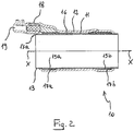
figure 2 is a schematic view of a longitudinal section of the screen connector offigure 1 ; -
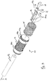
figure 3 is a schematic exploded view of the screen connector offigure 1 ; -
figure 4 is a schematic partially sectioned view of a first embodiment of a jointing assembly according to the present invention, in a specific operative configuration; -
figure 5 is a schematic partially sectioned view of a second embodiment of a jointing assembly according to the present invention, in a specific operative configuration; -
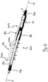
figure 6 is a schematic perspective view of a jointing assembly not part of the present invention, in a specific operative configuration. - With respect to
figures 1 to 3 , a screen connector for electrical cables according to the present disclosure is indicated withnumeral reference 10. Thescreen connector 10 is preferably adapted to be used with high voltage electrical cables. - As better explained in the following of the present description, the
screen connector 10 can be used for connecting an electrical cable to the ground, or to a termination, or to another electrical cable through a joint, or to another electrical cable associated with another joint. - The
screen connector 10 comprises a conductive shield sock 11 (not visible infigure 1 ) extending about a longitudinal axis X-X. - In a radially outer position with respect to the
conductive shield sock 11, a shrinkableprotective sleeve 12 made from an elastomeric material is provided. Infigure 3 theprotective sleeve 12 is shown in rest configuration, that is in radially collapsed state (before application over the conductive shield sock 11). - The
conductive shield sock 11 is adapted to be coaxially arranged onto a conductive screen of an electrical cable to provide electrical contact therewith. Similarly, theconductive shield sock 11 is adapted to be coaxially arranged onto a conductive screen of a cable joint or onto an end portion of a cable termination. If the termination has a conductive screen too, then theconductive shield sock 11 is adapted to be coaxially arranged onto said conductive screen. - For application on a cable joint, termination or the like, the shrinkable
protective sleeve 12 and theconductive shield sock 11 are held in a radially expanded state by aremovable support element 13 arranged in a radially inner position with respect to theconductive shield sock 11. - In the embodiment shown, the
support element 13 is a tubular element defining a helically wound strip (either helically wound or cut in a solid tube) . Said strip has afree end portion 13a adapted to be pulled in order to remove thesupport element 13 from thescreen connector 10, causing the shrinkableprotective sleeve 12 and theconductive shield sock 11 to radially collapse. - In an alternative embodiment not shown, the support element is a rigid tubular element adapted to be moved out from the screen connector by displacement along the longitudinal axis X-X.
- As shown in
figures 2 and3 , twowatertight elements support element 13 in a radially inner position with respect to theconductive shield sock 11, that is radially interposed between thesupport element 13 and theconductive shield sock 11. Preferably, the watertight elements are made by winding about thesupport element 13 at least one mastic tape. - One or more metallic braids (here two metallic braids are shown, both indicated with 16) lie onto the
conductive shield sock 11 so as to be radially interposed between saidconductive shield sock 11 and the shrinkableprotective sleeve 12. These metallic braids act as ground connectors. A singlemetallic braid 16 can be used in place of the two described above. No specific mechanical connection, such as welding, are required to maintain in the desired position the metallic braids 16. Indeed, maintenance of the desired position is achieved through the shrinking action exerted by the shrinkableprotective sleeve 12. - Two additional watertight elements are radially interposed between the
conductive shield sock 11 and the shrinkableprotective sleeve 12 at the opposite axial ends of thesupport element 13. Preferably, these additional watertight elements are made by winding mastic tapes 17a, 17b (seefigure 3 ) about theconductive shield sock 11 at the same axial position of thewatertight elements figure 2 ) . - In the example shown in
figures 1-3 , aconnection element 19 is firmly arranged within aseat 18 associated with the metallic braids 16. Theconnection element 19 is in particular a mechanical connector but other types of connection elements, e.g. mechanical punches, can be used in place of the mechanical connector, such as for example plug-in electrical connectors or lugs. - A different example of a
screen connector 10 in accordance with the present invention is shown infigure 4 . Specifically, twoscreen connectors 10a, 10b are shown infigure 4 , each one associated with a respectivefree end portion figure 5 ). The joint 50 offigure 4 is shown in a radially expanded state. - The
screen connectors 10a, 10b offigure 4 differ from that offigures 1 to 3 in that a plug-in electrical connector 20 is used in place of themechanical connector 19. In this case, each plug-in electrical connector 20 is associated with themetallic braids 16 by at least one elongated metallic arm 21a, 21b. Preferably, the metallic arms 21a, 21b are covered by a sheet of elastomeric material. -
Figure 5 shows a joint 50 with two electrical cables 100a, 100b connected thereto. Here, differently fromfigure 4 , twoscreen connectors 10a, 10b of the type above-described with reference tofigures 1 to 3 are used. Furthermore, the joint 50 is provided with an outer shield (described below) not shown infigure 4 . - The joint 50 of
figure 5 is shown in a collapsed configuration over the electrical cables 100a, 100b. - As shown in
figures 4 and5 , the joint 50 comprises aconnector 51 extending about a longitudinal axis corresponding to the longitudinal axis X-X of thescreen connectors 10a, 10b. - The
connector 51 is a socket connector, that is it comprises axially opposite end portions each provided with a seat adapted to house and lock into a desired axial position respective plug-in connectors 101a, 101b (figure 5 ) associated with a free end portion of a respective electrical cable. - The joint 50 comprises a radially
shrinkable sleeve 60, in a radially outer position with respect to theconnector 51. Thesleeve 60 can be made from heat or cold shrinkable dielectric materials. Preferably, thesleeve 60 is made of a cold shrinkable dielectric material, such as rubber EPDM. - The
sleeve 60 extends coaxially to the longitudinal axis X-X and has a length greater than that of theconnector 51. Theconnector 51 is centrally arranged within thesleeve 60 along the longitudinal axis X-X so as to have a symmetrical arrangement of thesleeve 60 about theconnector 51 along the longitudinal axis X-X. - The
sleeve 60 comprises, at a radially inner portion thereof, a firstcylindrical insert 61 made from a conductive or semi-conductive material. Throughout the following description, theinsert 61 will be indicated as "electrode". - The
electrode 61 is made from a cold shrinkable semi-conductive material. More preferably, such a material is rubber EPDM. - The
electrode 61 extends coaxially to the longitudinal axis X-X and has a length greater than that of theconnector 51 and lower than that of thesleeve 60. Theelectrode 61 is symmetrically arranged with respect theconnector 51 and thesleeve 60 along the longitudinal axis X-X. - The
sleeve 60 further comprises, at each of the end portions thereof, a respective secondcylindrical insert 62a, 62b, made from a conductive or semi-conductive material. Throughout the following description, theinserts 62a, 62b will be indicated as "deflectors". - The
deflectors 62a, 62b cooperate with theelectrode 61 to control the electrical field within thesleeve 60, in particular to avoid the presence of areas with high concentration of electrical field, wherein undesired electrical discharges and breakdowns could occur. - The
deflectors 62a, 62b are made from a cold shrinkable semi-conductive material. More preferably such a material is EPDM o silicone rubber. Alternatively, thedeflectors 62a, 62b are made from a high permittivity material. - Each of the
deflectors 62a, 62b extends coaxially to the longitudinal axis X-X and axially projects inside thesleeve 60 toward theelectrode 61 so that the radially inner portion of thesleeve 60 is defined, moving from the central portion toward each of the end portions thereof, by theelectrode 61, the dielectric material of thesleeve 60 and thedeflector 62a, 62b. - In the joint 50 of
figure 4 theelectrode 61 and thedeflectors 62a, 62b are incorporated into the dielectric material of thesleeve 60. - In an alternative example (not shown and not part of the invention), the electrode and the deflectors are not incorporated into the dielectric material of the
sleeve 60, but are arranged in a radially inner position with respect to the radially inner surface of thesleeve 60. - As shown in
figure 4 , thesleeve 60 is initially held in a radially expanded state by two support elements 70a, 70b which are arranged in a radially inner position with respect to thesleeve 60, theelectrode 61 and thedeflectors 62a, 62b. - In this configuration, the support elements 70a, 70b are associated with each other by a connecting
element 71 adapted to hold the support elements 70a, 70b within the sleeve 20. Only the opposite free end portions of the connectingelement 71 are visible infigure 4 . - After having mechanically and electrically coupled the two electrical cables 100a, 100b to the
connector 51, the support elements 70a, 70b are axially removed from the opposite end portions of thesleeve 60 along opposite directions, thus causing thesleeve 60, together with theelectrode 61 and thedeflectors 62a, 62b, to shrink onto the electrical cables 100a, 100b, so as to take the configuration shown infigure 5 . In order to remove the support elements 70a, 70b, the aforementioned connectingelement 71 is broken. - In the embodiment shown in
figure 4 , each support element 70a, 70b comprises a tubular rigid body made from a plastic material. Preferably, each of the tubular rigid body is made of a charged homopolymer polypropylene. - In an alternative embodiment (not shown) of the jointing assembly, each support element is a tubular element defining a helically wound strip (either helically wound or cut in a solid tube). The strip is adapted to be removed from the respective end portion of the sleeve by pulling a free end portion of the strip.
- As better shown in
figure 5 , the joint 50 further comprises, in a radially outer position with respect to thesleeve 60, afirst shield 80. Theshield 80 has a length substantially equal to that of thesleeve 60. - Preferably, the
shield 80 is made of a two-layer sheath including an radially inner layer and a radially outer layer. - The radially inner layer is preferably made from a dielectric material, more preferably rubber EPDM, while the radially outer layer is preferably made from a semi-conductive material, more preferably rubber EPDM.
- In a radially outer position with respect to the
first shield 80, ametallic screen 90 is provided. Thescreen 90 has a length greater than that of thesleeve 60 and is preferably made of tinned copper. - The joint 50 further comprises, in a radially outer position with respect to the
screen 90, asecond shield 95 having preferably a length substantially equal to that of thescreen 90. - Preferably, the
shield 95 is made of a two-layer sheath, that is it includes a radially inner layer made from a dielectric material and a radially outer layer made from a semi-conductive material. More preferably, the same material of theshield 80 is used. - As far as the electrical cables 100a, 100b are concerned, as shown in
figure 5 , the conductors of each electrical cable 100a, 100b are covered by an insulating layer 102a, 102b. A conductive screen 103a, 103b is coaxially applied at a radially outer position to the insulating layer 102a, 102b, 4b. The conductive screen 103a, 103b is in turn covered with at least one protective sheath 104a, 104b of electrically insulating plastic or elastomeric material. - Preferably each electrical cable 100a, 100b further comprises at least one
semi-conductive layer 105a, 105b radially interposed between the insulating layer 102a, 102b and the conductive screen 103a, 103b. - In the embodiment of
figure 5 , the conductive screen 103a, 103b of the electrical cables 100a, 100b are electrically connected to each other through themetallic screen 90 of the joint 50. - To this end, the opposite end portions of the
second shield 95 of the joint 50 are folded back toward each other (or, in an alternative embodiment not shown, they are held in a radially expanded state by respective removable rigid bodies) and each of the opposite free end portions of themetallic screen 90 is arranged in a radially outer position with respect to a respective conductive screen 103a, 103b of a respective electrical cable 100a, 100b. - Advantageously, each
screen connector 10a, 10b is in turn arranged in a radially outer position with respect to the aforementioned free end portions of themetallic screen 90 of the joint 50 so that, upon removal of thesupport element 13 of thescreen connector 10a, 10b, the shrinkableprotective sleeve 12 and theconductive shield sock 11 of thescreen connectors 10a, 10b shrunk onto themetallic screen 90 of the joint 50 and the conductive screen 103a, 103b of the electrical cable 100a, 100b, obtaining the desired electrical contact between conductive screen 103a, 103b,metallic screen 90 andconductive shield sock 11. - Afterwards, the opposite end portions of the
second shield 95 of the joint 50 are unfolded to fully cover thescreen connectors 10a, 10b, leaving out just theconnection elements 19. - The embodiment of
figure 5 allows each of the conductive screen 103a, 103b of the electrical cables 100a, 100b connected to the joint 50 to be connected through thescreen connectors 10a, 10b to the ground. - The embodiment of
figure 5 also allows each of the conductive screen 103a, 103b of the electrical cables 100a, 100b connected to the joint 50 to be connected to an electrical cable connected to another joint. - In a different embodiment not shown, the
screen connectors 10a, 10b are associated with a joint as that offigures 4 and5 , themetallic screen 90 is provided, but it is interrupted. In this case, the reciprocal electrical connection between the conductive screen 103a, 103b of the two electrical cables 100a, 100b can be achieve by connecting to each other the plug-in electrical connectors 20a, 20b are associated with each other. Of course, in this case one of the electrical connectors 20a, 20b could be a male connector and the other one could be a female connector. -
Figure 6 shows a jointing assembly not part of the present invention. In this assembly thescreen connector 10 is associated with atermination 200 which is in turn associated with anelectrical cable 100. - The
termination 200 comprises ashrinkable body 201 extending about a longitudinal axis X-X. Theshrinkable body 201 is made from dielectric material. - The
shrinkable body 201 comprises aportion 210 shaped so as to define a plurality of fins (all indicated with 210a) . - A
deflector 262 for controlling the electrical field is incorporated in the material of theshrinkable body 201. - The
electrical cable 100 is inserted in an axial cavity of theshrinkable body 201 and is connected with a plug-inconnector 202 housed in acap 203 associated with a free end portion 201a of theshrinkable body 201. Thecap 203 is made of an elastomeric material. - On the axially opposite free end portion 201b of the shrinkable body 201 a
screen connector 10 of the above-described is provided. In particular, an end portion of thescreen connector 10 is arranged in a radially inner position with respect to the end portion 201b of theshrinkable body 201 so as to provide an electrical connection between theconductive shield sock 11 of thescreen connector 10 and the conductive screen of theelectrical cable 100. By this way, theelectrical cable 100 can be connected to the ground. - The
shrinkable body 201 is held in a radially expanded state by a removable support element (not visible) arranged in a radially inner position thereto. When this support element is removed, theshrinkable body 201 collapses onto theelectrical cable 100. The removable support element can be a tube cut into a helically wound strip or a removable rigid tubular element, similarly to what stated above with respect to the removable support element of thescreen connector 10 and of the joint 50. - The termination may or not be provided with a conductive screen. Should the conductive screen be provided, the
conductive shield sock 11 of thescreen connector 10 is preferably arranged in a radially outer position with respect to the conductive screen of the termination. - The skilled person will understand that, starting from the above described different embodiments of the jointing assembly of the present invention, a plurality of further different embodiments can be foreseen by combining in different ways the various features described above. All these embodiments are indeed encompassed by the present invention as defined by the attached claims.
Claims (8)
- Jointing assembly (50) for electrical cables, comprising two electrical cables (100a, 100b) having a respective end portion, the jointing assembly (50) being configured to be in a radially expanded state or in a radially collapsed state onto the end portions of the respective electrical cables (100a, 100b) and comprising a radially shrinkable sleeve (60) made from a dielectric material and extending about a longitudinal axis (X-X),
a main connector (51) configured to be associated with the end portions of the electrical cables (100a, 100b), the jointing assembly (50) further comprising two screen connectors (10a, 10b) at respective axial end portions of said radially shrinkable sleeve (60),
each screen connector (10a, 10b) comprising a conductive shield sock (11) extending about the longitudinal axis (X-X) and adapted to be coupled in the radially collapsed state to a conductive screen (103a, 103b) of the respective electrical cable (100a, 100b) and a shrinkable protective sleeve (12) being arranged in a radially outer position with respect to said conductive shield sock (11), wherein
when the jointing assembly (50) is in the radially expanded state, each screen connector (10a, 10b) comprises at least one removable support element (13) coaxially arranged in a radially inner position with respect to said conductive shield sock (11) and adapted to hold said conductive shield sock (11) and said shrinkable protective sleeve (12) in the radially expanded state, and
when the jointing assembly (50) is in the collapsed state, said radially shrinkable sleeve (60) is radially collapsed onto said main connector (51) and the respective end portion of the electrical cables (100a, 100b),
the jointing assembly (50) further comprising:at a radial inner portion of the shrinkable sleeve (60), an electrode (61) as first cylindrical insert, the electrode (61) extending coaxially along the longitudinal axis (X-X) with a length larger than that of the main connector (51) and smaller than that of the shrinkable sleeve (60), the electrode (61) being symmetrically arranged with respect the main connector (51) and the shrinkable sleeve (60) along the longitudinal axis (X-X);at each of the end portions of the shrinkable sleeve (60), a respective deflector (62a, 62b) as second cylindrical insert, the deflectors (62a, 62b) extending coaxially along the longitudinal axis (X-X) and axially projecting inside the shrinkable sleeve (60) toward the electrode (61) so that the radially inner portion of the sleeve (60) is defined, moving from its central portion toward each of the end portions thereof, by the electrode (61), the dielectric material of the sleeve (60) and the deflector (62a, 62b), wherein the deflectors (62a, 62b) and the electrode (61) are made from a cold shrinkable semi-conductive material;a first shield (80) in a radially outer position with respect to the radially shrinkable sleeve (60) and a metallic screen (90) in a radially outer position with respect to the first shield (80), the first shield (80) having a length substantially equal to that of the radially shrinkable sleeve (60) and the metallic screen (90) having a length greater than that of the radially shrinkable sleeve (60), wherein the metallic screen (90) is configured such that the conductive screens (103a, 103b) of the respective electrical cables (100a, 100b) are electrically connectable to each other through the metallic screen (90),wherein each screen connector (10a, 10b) is arranged in a radially outer position with respect to opposite free end portions of the metallic screen (90) so that, upon removal of the removable support element (13), the shrinkable protective sleeve (12) and the conductive shield sock (11) of the screen connectors (10a, 10b) shrink onto the metallic screen (90) and the conductive screen (103a, 103b) of the electrical cable (100a, 100b), thereby forming an electrical contact between the conductive screen (103a, 103b), the metallic screen (90) and the conductive shield sock (11). - Jointing assembly according to claim 1, wherein each screen connector (10a, 10b) comprises at the axially opposite end portions thereof, at least one first watertight element (15a, 15b) radially interposed between said at least one removable support element (13) and said shrinkable protective sleeve (12).
- Jointing assembly according to claim 2, wherein said at least one first watertight element (15a, 15b) is radially interposed between said at least one removable support element (13) and said conductive shield sock (11).
- Jointing assembly according to claim 2 or 3, wherein each screen connector (10a, 10b) comprises at the axially opposite end portions thereof, at least one second watertight element (17a, 17b), said at least one second watertight element (17a, 17b) being radially interposed between said conductive shield sock (11) and said shrinkable protective sleeve (12).
- Jointing assembly according to any of the previous claims, wherein each screen connector (10a, 10b) further comprises at least one metallic braid (16) coupled to said conductive shield sock (11) and radially interposed between said conductive shield sock (11) and said shrinkable protective sleeve (12).
- Jointing assembly according to any of the previous claims, wherein each screen connector (10a, 10b) further comprises a connection element (19, 20a, 20b), associated with said conductive shield sock (11), wherein said connection element (19, 20a, 20b), is a plug-in electrical connector, or a lug or a mechanical connector.
- Jointing assembly according to any of the previous claims, wherein said at least one removable support element (13) comprises a tubular element defined by a rigid body.
- Jointing assembly according to any of claims 1 to 6, wherein said at least one removable support element (13) comprises a tubular element defined by a helically wound strip.
Applications Claiming Priority (1)
| Application Number | Priority Date | Filing Date | Title |
|---|---|---|---|
| PCT/EP2010/007853 WO2012083986A1 (en) | 2010-12-22 | 2010-12-22 | Screen connector for electrical cables and jointing assembly comprising said screen connector |
Publications (2)
| Publication Number | Publication Date |
|---|---|
| EP2656465A1 EP2656465A1 (en) | 2013-10-30 |
| EP2656465B1 true EP2656465B1 (en) | 2021-07-14 |
Family
ID=44583730
Family Applications (1)
| Application Number | Title | Priority Date | Filing Date |
|---|---|---|---|
| EP10805206.9A Active EP2656465B1 (en) | 2010-12-22 | 2010-12-22 | Screen connector for electrical cables and jointing assembly comprising said screen connector |
Country Status (10)
| Country | Link |
|---|---|
| US (1) | US9590410B2 (en) |
| EP (1) | EP2656465B1 (en) |
| CN (1) | CN103299500B (en) |
| AR (1) | AR084420A1 (en) |
| AU (1) | AU2010366147B2 (en) |
| BR (1) | BR112013015784B1 (en) |
| CA (1) | CA2819926C (en) |
| NZ (1) | NZ611637A (en) |
| RU (1) | RU2558669C2 (en) |
| WO (1) | WO2012083986A1 (en) |
Families Citing this family (2)
| Publication number | Priority date | Publication date | Assignee | Title |
|---|---|---|---|---|
| EP3516749B1 (en) * | 2016-09-19 | 2023-11-01 | Prysmian S.p.A. | Joint for high voltage direct current cables |
| US10923860B2 (en) * | 2019-02-25 | 2021-02-16 | J.S.T. Corporation | Method for shielding and grounding a connector assembly from electromagnetic interference (EMI) using conductive seal and conductive housing |
Citations (2)
| Publication number | Priority date | Publication date | Assignee | Title |
|---|---|---|---|---|
| EP0780949A1 (en) * | 1995-12-23 | 1997-06-25 | Minnesota Mining And Manufacturing Company | Universal cable adapter, cable joint using the adapter and method of making the same |
| US20080257259A1 (en) * | 2004-10-27 | 2008-10-23 | Ubaldo Vallauri | Method and Device for Coating the Junction Area Between at Least Two Elongated Elements, in Particular Between Electric Cables |
Family Cites Families (14)
| Publication number | Priority date | Publication date | Assignee | Title |
|---|---|---|---|---|
| US3163707A (en) * | 1962-12-27 | 1964-12-29 | Ralph E Darling | Non-stretch flexible tube with conductors therein |
| US3728472A (en) * | 1972-03-31 | 1973-04-17 | Gen Cable Corp | Mechanical pressure type electrical connections for terminating and connecting metallic cable shields |
| SU720594A1 (en) * | 1978-03-24 | 1980-03-05 | Предприятие П/Я В-2156 | Electrical connector for shielded cables |
| US4435639A (en) * | 1982-09-15 | 1984-03-06 | Raychem Corporation | Electrical devices with water-blocking insulation |
| US4667064A (en) * | 1985-12-10 | 1987-05-19 | Sheu Chin Chang | Cable connector structure |
| DE3602150A1 (en) * | 1986-01-24 | 1987-07-30 | Minnesota Mining & Mfg | MEDIUM VOLTAGE CABLE CONNECTION, IN PARTICULAR FOR OIL-FILLED PAPER INSULATED CABLES |
| RU2093937C1 (en) * | 1989-05-05 | 1997-10-20 | Научно-производственное объединение им.С.А.Лавочкина | Unit for terminating composite shielded cable into connector |
| US5315063A (en) * | 1992-09-10 | 1994-05-24 | Electric Motion Company, Inc. | Ground connector |
| WO1998040941A1 (en) | 1997-03-13 | 1998-09-17 | Minnesota Mining And Manufacturing Company | Compact covering device |
| US6103975A (en) * | 1998-06-29 | 2000-08-15 | 3M Innovative Properties Company | Pre-assembled electrical splice component |
| FR2899733B1 (en) | 2006-04-05 | 2008-07-04 | Nexans Sa | CABLE ADAPTER, TUBULAR FOR JUNCTION OR TERMINATION OF MEDIUM VOLTAGE CABLE |
| ATE450914T1 (en) * | 2006-05-05 | 2009-12-15 | 3M Innovative Properties Co | TUBULAR CABLE CONNECTION |
| US8445783B2 (en) | 2009-02-05 | 2013-05-21 | 3M Innovative Properties Company | Splice assembly with shield sock |
| US8030570B2 (en) * | 2009-05-01 | 2011-10-04 | Tyco Electronics Corporation | Cover assemblies for cables and electrical connections and methods for making and using the same |
-
2010
- 2010-12-22 NZ NZ611637A patent/NZ611637A/en unknown
- 2010-12-22 US US13/992,957 patent/US9590410B2/en active Active
- 2010-12-22 CN CN201080070824.6A patent/CN103299500B/en active Active
- 2010-12-22 EP EP10805206.9A patent/EP2656465B1/en active Active
- 2010-12-22 WO PCT/EP2010/007853 patent/WO2012083986A1/en not_active Ceased
- 2010-12-22 CA CA2819926A patent/CA2819926C/en active Active
- 2010-12-22 BR BR112013015784-4A patent/BR112013015784B1/en active IP Right Grant
- 2010-12-22 AU AU2010366147A patent/AU2010366147B2/en active Active
- 2010-12-22 RU RU2013133699/07A patent/RU2558669C2/en active
-
2011
- 2011-12-20 AR ARP110104795A patent/AR084420A1/en active IP Right Grant
Patent Citations (2)
| Publication number | Priority date | Publication date | Assignee | Title |
|---|---|---|---|---|
| EP0780949A1 (en) * | 1995-12-23 | 1997-06-25 | Minnesota Mining And Manufacturing Company | Universal cable adapter, cable joint using the adapter and method of making the same |
| US20080257259A1 (en) * | 2004-10-27 | 2008-10-23 | Ubaldo Vallauri | Method and Device for Coating the Junction Area Between at Least Two Elongated Elements, in Particular Between Electric Cables |
Also Published As
| Publication number | Publication date |
|---|---|
| EP2656465A1 (en) | 2013-10-30 |
| CA2819926A1 (en) | 2012-06-28 |
| RU2013133699A (en) | 2015-01-27 |
| US20140000928A1 (en) | 2014-01-02 |
| NZ611637A (en) | 2015-03-27 |
| AU2010366147B2 (en) | 2016-08-04 |
| AU2010366147A1 (en) | 2013-07-04 |
| WO2012083986A1 (en) | 2012-06-28 |
| CA2819926C (en) | 2018-01-23 |
| US9590410B2 (en) | 2017-03-07 |
| RU2558669C2 (en) | 2015-08-10 |
| CN103299500B (en) | 2017-09-22 |
| AR084420A1 (en) | 2013-05-15 |
| CN103299500A (en) | 2013-09-11 |
| BR112013015784B1 (en) | 2020-03-10 |
| BR112013015784A2 (en) | 2018-06-12 |
Similar Documents
| Publication | Publication Date | Title |
|---|---|---|
| TWI429155B (en) | Tubular terminal for a cable | |
| EP1092252B1 (en) | Pre-assembled electrical splice component | |
| CN102308448B (en) | Connector assembly with shield sleeve | |
| EP1966863B1 (en) | Joining method and related junction for electric cables | |
| JP7033212B2 (en) | High voltage cable joint structure | |
| CA2819928C (en) | Process for manufacturing a jointing assembly for medium or high voltage electrical cables and jointing assembly obtainable by said process | |
| EP2656464B1 (en) | Jointing assembly for electrical cables | |
| GB2099638A (en) | Improvements relating to jointing and/or terminating electric cables | |
| EP1852949B1 (en) | Tubular terminal for a cable | |
| CA2819926C (en) | Screen connector for electrical cables and jointing assembly comprising said screen connector | |
| CN206759022U (en) | Cable connector assembly and cable connector system |
Legal Events
| Date | Code | Title | Description |
|---|---|---|---|
| PUAI | Public reference made under article 153(3) epc to a published international application that has entered the european phase |
Free format text: ORIGINAL CODE: 0009012 |
|
| 17P | Request for examination filed |
Effective date: 20130715 |
|
| AK | Designated contracting states |
Kind code of ref document: A1 Designated state(s): AL AT BE BG CH CY CZ DE DK EE ES FI FR GB GR HR HU IE IS IT LI LT LU LV MC MK MT NL NO PL PT RO RS SE SI SK SM TR |
|
| DAX | Request for extension of the european patent (deleted) | ||
| STAA | Information on the status of an ep patent application or granted ep patent |
Free format text: STATUS: EXAMINATION IS IN PROGRESS |
|
| 17Q | First examination report despatched |
Effective date: 20170201 |
|
| RAP1 | Party data changed (applicant data changed or rights of an application transferred) |
Owner name: PRYSMIAN S.P.A. |
|
| GRAP | Despatch of communication of intention to grant a patent |
Free format text: ORIGINAL CODE: EPIDOSNIGR1 |
|
| STAA | Information on the status of an ep patent application or granted ep patent |
Free format text: STATUS: GRANT OF PATENT IS INTENDED |
|
| INTG | Intention to grant announced |
Effective date: 20210406 |
|
| GRAS | Grant fee paid |
Free format text: ORIGINAL CODE: EPIDOSNIGR3 |
|
| GRAA | (expected) grant |
Free format text: ORIGINAL CODE: 0009210 |
|
| STAA | Information on the status of an ep patent application or granted ep patent |
Free format text: STATUS: THE PATENT HAS BEEN GRANTED |
|
| AK | Designated contracting states |
Kind code of ref document: B1 Designated state(s): AL AT BE BG CH CY CZ DE DK EE ES FI FR GB GR HR HU IE IS IT LI LT LU LV MC MK MT NL NO PL PT RO RS SE SI SK SM TR |
|
| REG | Reference to a national code |
Ref country code: GB Ref legal event code: FG4D |
|
| REG | Reference to a national code |
Ref country code: IE Ref legal event code: FG4D |
|
| REG | Reference to a national code |
Ref country code: DE Ref legal event code: R096 Ref document number: 602010067271 Country of ref document: DE |
|
| REG | Reference to a national code |
Ref country code: AT Ref legal event code: REF Ref document number: 1411398 Country of ref document: AT Kind code of ref document: T Effective date: 20210815 |
|
| REG | Reference to a national code |
Ref country code: LT Ref legal event code: MG9D |
|
| REG | Reference to a national code |
Ref country code: NL Ref legal event code: MP Effective date: 20210714 |
|
| REG | Reference to a national code |
Ref country code: AT Ref legal event code: MK05 Ref document number: 1411398 Country of ref document: AT Kind code of ref document: T Effective date: 20210714 |
|
| PG25 | Lapsed in a contracting state [announced via postgrant information from national office to epo] |
Ref country code: NO Free format text: LAPSE BECAUSE OF FAILURE TO SUBMIT A TRANSLATION OF THE DESCRIPTION OR TO PAY THE FEE WITHIN THE PRESCRIBED TIME-LIMIT Effective date: 20211014 Ref country code: RS Free format text: LAPSE BECAUSE OF FAILURE TO SUBMIT A TRANSLATION OF THE DESCRIPTION OR TO PAY THE FEE WITHIN THE PRESCRIBED TIME-LIMIT Effective date: 20210714 Ref country code: NL Free format text: LAPSE BECAUSE OF FAILURE TO SUBMIT A TRANSLATION OF THE DESCRIPTION OR TO PAY THE FEE WITHIN THE PRESCRIBED TIME-LIMIT Effective date: 20210714 Ref country code: PT Free format text: LAPSE BECAUSE OF FAILURE TO SUBMIT A TRANSLATION OF THE DESCRIPTION OR TO PAY THE FEE WITHIN THE PRESCRIBED TIME-LIMIT Effective date: 20211115 Ref country code: ES Free format text: LAPSE BECAUSE OF FAILURE TO SUBMIT A TRANSLATION OF THE DESCRIPTION OR TO PAY THE FEE WITHIN THE PRESCRIBED TIME-LIMIT Effective date: 20210714 Ref country code: FI Free format text: LAPSE BECAUSE OF FAILURE TO SUBMIT A TRANSLATION OF THE DESCRIPTION OR TO PAY THE FEE WITHIN THE PRESCRIBED TIME-LIMIT Effective date: 20210714 Ref country code: BG Free format text: LAPSE BECAUSE OF FAILURE TO SUBMIT A TRANSLATION OF THE DESCRIPTION OR TO PAY THE FEE WITHIN THE PRESCRIBED TIME-LIMIT Effective date: 20211014 Ref country code: AT Free format text: LAPSE BECAUSE OF FAILURE TO SUBMIT A TRANSLATION OF THE DESCRIPTION OR TO PAY THE FEE WITHIN THE PRESCRIBED TIME-LIMIT Effective date: 20210714 Ref country code: LT Free format text: LAPSE BECAUSE OF FAILURE TO SUBMIT A TRANSLATION OF THE DESCRIPTION OR TO PAY THE FEE WITHIN THE PRESCRIBED TIME-LIMIT Effective date: 20210714 Ref country code: HR Free format text: LAPSE BECAUSE OF FAILURE TO SUBMIT A TRANSLATION OF THE DESCRIPTION OR TO PAY THE FEE WITHIN THE PRESCRIBED TIME-LIMIT Effective date: 20210714 Ref country code: SE Free format text: LAPSE BECAUSE OF FAILURE TO SUBMIT A TRANSLATION OF THE DESCRIPTION OR TO PAY THE FEE WITHIN THE PRESCRIBED TIME-LIMIT Effective date: 20210714 |
|
| PG25 | Lapsed in a contracting state [announced via postgrant information from national office to epo] |
Ref country code: PL Free format text: LAPSE BECAUSE OF FAILURE TO SUBMIT A TRANSLATION OF THE DESCRIPTION OR TO PAY THE FEE WITHIN THE PRESCRIBED TIME-LIMIT Effective date: 20210714 Ref country code: LV Free format text: LAPSE BECAUSE OF FAILURE TO SUBMIT A TRANSLATION OF THE DESCRIPTION OR TO PAY THE FEE WITHIN THE PRESCRIBED TIME-LIMIT Effective date: 20210714 Ref country code: GR Free format text: LAPSE BECAUSE OF FAILURE TO SUBMIT A TRANSLATION OF THE DESCRIPTION OR TO PAY THE FEE WITHIN THE PRESCRIBED TIME-LIMIT Effective date: 20211015 |
|
| REG | Reference to a national code |
Ref country code: DE Ref legal event code: R097 Ref document number: 602010067271 Country of ref document: DE |
|
| PG25 | Lapsed in a contracting state [announced via postgrant information from national office to epo] |
Ref country code: DK Free format text: LAPSE BECAUSE OF FAILURE TO SUBMIT A TRANSLATION OF THE DESCRIPTION OR TO PAY THE FEE WITHIN THE PRESCRIBED TIME-LIMIT Effective date: 20210714 |
|
| PLBE | No opposition filed within time limit |
Free format text: ORIGINAL CODE: 0009261 |
|
| STAA | Information on the status of an ep patent application or granted ep patent |
Free format text: STATUS: NO OPPOSITION FILED WITHIN TIME LIMIT |
|
| PG25 | Lapsed in a contracting state [announced via postgrant information from national office to epo] |
Ref country code: SM Free format text: LAPSE BECAUSE OF FAILURE TO SUBMIT A TRANSLATION OF THE DESCRIPTION OR TO PAY THE FEE WITHIN THE PRESCRIBED TIME-LIMIT Effective date: 20210714 Ref country code: SK Free format text: LAPSE BECAUSE OF FAILURE TO SUBMIT A TRANSLATION OF THE DESCRIPTION OR TO PAY THE FEE WITHIN THE PRESCRIBED TIME-LIMIT Effective date: 20210714 Ref country code: RO Free format text: LAPSE BECAUSE OF FAILURE TO SUBMIT A TRANSLATION OF THE DESCRIPTION OR TO PAY THE FEE WITHIN THE PRESCRIBED TIME-LIMIT Effective date: 20210714 Ref country code: EE Free format text: LAPSE BECAUSE OF FAILURE TO SUBMIT A TRANSLATION OF THE DESCRIPTION OR TO PAY THE FEE WITHIN THE PRESCRIBED TIME-LIMIT Effective date: 20210714 Ref country code: CZ Free format text: LAPSE BECAUSE OF FAILURE TO SUBMIT A TRANSLATION OF THE DESCRIPTION OR TO PAY THE FEE WITHIN THE PRESCRIBED TIME-LIMIT Effective date: 20210714 Ref country code: AL Free format text: LAPSE BECAUSE OF FAILURE TO SUBMIT A TRANSLATION OF THE DESCRIPTION OR TO PAY THE FEE WITHIN THE PRESCRIBED TIME-LIMIT Effective date: 20210714 |
|
| 26N | No opposition filed |
Effective date: 20220419 |
|
| PG25 | Lapsed in a contracting state [announced via postgrant information from national office to epo] |
Ref country code: MC Free format text: LAPSE BECAUSE OF FAILURE TO SUBMIT A TRANSLATION OF THE DESCRIPTION OR TO PAY THE FEE WITHIN THE PRESCRIBED TIME-LIMIT Effective date: 20210714 |
|
| REG | Reference to a national code |
Ref country code: CH Ref legal event code: PL |
|
| REG | Reference to a national code |
Ref country code: BE Ref legal event code: MM Effective date: 20211231 |
|
| PG25 | Lapsed in a contracting state [announced via postgrant information from national office to epo] |
Ref country code: LU Free format text: LAPSE BECAUSE OF NON-PAYMENT OF DUE FEES Effective date: 20211222 Ref country code: IE Free format text: LAPSE BECAUSE OF NON-PAYMENT OF DUE FEES Effective date: 20211222 |
|
| PG25 | Lapsed in a contracting state [announced via postgrant information from national office to epo] |
Ref country code: BE Free format text: LAPSE BECAUSE OF NON-PAYMENT OF DUE FEES Effective date: 20211231 |
|
| PG25 | Lapsed in a contracting state [announced via postgrant information from national office to epo] |
Ref country code: LI Free format text: LAPSE BECAUSE OF NON-PAYMENT OF DUE FEES Effective date: 20211231 Ref country code: CH Free format text: LAPSE BECAUSE OF NON-PAYMENT OF DUE FEES Effective date: 20211231 |
|
| PG25 | Lapsed in a contracting state [announced via postgrant information from national office to epo] |
Ref country code: HU Free format text: LAPSE BECAUSE OF FAILURE TO SUBMIT A TRANSLATION OF THE DESCRIPTION OR TO PAY THE FEE WITHIN THE PRESCRIBED TIME-LIMIT; INVALID AB INITIO Effective date: 20101222 Ref country code: CY Free format text: LAPSE BECAUSE OF FAILURE TO SUBMIT A TRANSLATION OF THE DESCRIPTION OR TO PAY THE FEE WITHIN THE PRESCRIBED TIME-LIMIT Effective date: 20210714 |
|
| PG25 | Lapsed in a contracting state [announced via postgrant information from national office to epo] |
Ref country code: MK Free format text: LAPSE BECAUSE OF FAILURE TO SUBMIT A TRANSLATION OF THE DESCRIPTION OR TO PAY THE FEE WITHIN THE PRESCRIBED TIME-LIMIT Effective date: 20210714 |
|
| PG25 | Lapsed in a contracting state [announced via postgrant information from national office to epo] |
Ref country code: MT Free format text: LAPSE BECAUSE OF FAILURE TO SUBMIT A TRANSLATION OF THE DESCRIPTION OR TO PAY THE FEE WITHIN THE PRESCRIBED TIME-LIMIT Effective date: 20210714 |
|
| PG25 | Lapsed in a contracting state [announced via postgrant information from national office to epo] |
Ref country code: TR Free format text: LAPSE BECAUSE OF FAILURE TO SUBMIT A TRANSLATION OF THE DESCRIPTION OR TO PAY THE FEE WITHIN THE PRESCRIBED TIME-LIMIT Effective date: 20210714 |
|
| PGFP | Annual fee paid to national office [announced via postgrant information from national office to epo] |
Ref country code: GB Payment date: 20251229 Year of fee payment: 16 |
|
| PGFP | Annual fee paid to national office [announced via postgrant information from national office to epo] |
Ref country code: IT Payment date: 20251219 Year of fee payment: 16 |
|
| PGFP | Annual fee paid to national office [announced via postgrant information from national office to epo] |
Ref country code: FR Payment date: 20251226 Year of fee payment: 16 |
|
| PGFP | Annual fee paid to national office [announced via postgrant information from national office to epo] |
Ref country code: DE Payment date: 20251229 Year of fee payment: 16 |