EP2655784B1 - Earth removal member with features for facilitating drill-through - Google Patents
Earth removal member with features for facilitating drill-through Download PDFInfo
- Publication number
- EP2655784B1 EP2655784B1 EP11808800.4A EP11808800A EP2655784B1 EP 2655784 B1 EP2655784 B1 EP 2655784B1 EP 11808800 A EP11808800 A EP 11808800A EP 2655784 B1 EP2655784 B1 EP 2655784B1
- Authority
- EP
- European Patent Office
- Prior art keywords
- blade
- nose
- removal member
- earth removal
- blade support
- Prior art date
- Legal status (The legal status is an assumption and is not a legal conclusion. Google has not performed a legal analysis and makes no representation as to the accuracy of the status listed.)
- Not-in-force
Links
- 238000005553 drilling Methods 0.000 claims description 22
- 239000000463 material Substances 0.000 claims description 22
- 230000013011 mating Effects 0.000 claims description 22
- 229910052782 aluminium Inorganic materials 0.000 claims description 14
- XAGFODPZIPBFFR-UHFFFAOYSA-N aluminium Chemical compound [Al] XAGFODPZIPBFFR-UHFFFAOYSA-N 0.000 claims description 14
- 238000000034 method Methods 0.000 claims description 14
- 229910000831 Steel Inorganic materials 0.000 claims description 9
- 239000010959 steel Substances 0.000 claims description 9
- 229910001018 Cast iron Inorganic materials 0.000 claims description 2
- 230000000717 retained effect Effects 0.000 claims description 2
- 239000004411 aluminium Substances 0.000 claims 3
- 239000012530 fluid Substances 0.000 description 12
- 239000003381 stabilizer Substances 0.000 description 12
- 238000003466 welding Methods 0.000 description 5
- 239000000853 adhesive Substances 0.000 description 4
- 230000001070 adhesive effect Effects 0.000 description 4
- 229910045601 alloy Inorganic materials 0.000 description 3
- 239000000956 alloy Substances 0.000 description 3
- 230000015572 biosynthetic process Effects 0.000 description 3
- 239000002131 composite material Substances 0.000 description 3
- 229910003460 diamond Inorganic materials 0.000 description 3
- 239000010432 diamond Substances 0.000 description 3
- 238000005755 formation reaction Methods 0.000 description 3
- 230000008901 benefit Effects 0.000 description 2
- 238000005219 brazing Methods 0.000 description 2
- 239000011195 cermet Substances 0.000 description 2
- 239000011248 coating agent Substances 0.000 description 2
- 238000000576 coating method Methods 0.000 description 2
- 230000000295 complement effect Effects 0.000 description 2
- 239000007789 gas Substances 0.000 description 2
- 238000004519 manufacturing process Methods 0.000 description 2
- 229910052751 metal Inorganic materials 0.000 description 2
- 239000002184 metal Substances 0.000 description 2
- 239000011435 rock Substances 0.000 description 2
- 238000000926 separation method Methods 0.000 description 2
- 238000005476 soldering Methods 0.000 description 2
- 229910052582 BN Inorganic materials 0.000 description 1
- PZNSFCLAULLKQX-UHFFFAOYSA-N Boron nitride Chemical compound N#B PZNSFCLAULLKQX-UHFFFAOYSA-N 0.000 description 1
- 229910001369 Brass Inorganic materials 0.000 description 1
- 229910000906 Bronze Inorganic materials 0.000 description 1
- RYGMFSIKBFXOCR-UHFFFAOYSA-N Copper Chemical compound [Cu] RYGMFSIKBFXOCR-UHFFFAOYSA-N 0.000 description 1
- 239000004593 Epoxy Substances 0.000 description 1
- ATJFFYVFTNAWJD-UHFFFAOYSA-N Tin Chemical compound [Sn] ATJFFYVFTNAWJD-UHFFFAOYSA-N 0.000 description 1
- HCHKCACWOHOZIP-UHFFFAOYSA-N Zinc Chemical compound [Zn] HCHKCACWOHOZIP-UHFFFAOYSA-N 0.000 description 1
- 238000013459 approach Methods 0.000 description 1
- QVGXLLKOCUKJST-UHFFFAOYSA-N atomic oxygen Chemical compound [O] QVGXLLKOCUKJST-UHFFFAOYSA-N 0.000 description 1
- 239000010951 brass Substances 0.000 description 1
- 239000010974 bronze Substances 0.000 description 1
- 238000005266 casting Methods 0.000 description 1
- 230000001413 cellular effect Effects 0.000 description 1
- 239000000919 ceramic Substances 0.000 description 1
- 229910052802 copper Inorganic materials 0.000 description 1
- 239000010949 copper Substances 0.000 description 1
- KUNSUQLRTQLHQQ-UHFFFAOYSA-N copper tin Chemical compound [Cu].[Sn] KUNSUQLRTQLHQQ-UHFFFAOYSA-N 0.000 description 1
- 230000008878 coupling Effects 0.000 description 1
- 238000010168 coupling process Methods 0.000 description 1
- 238000005859 coupling reaction Methods 0.000 description 1
- 230000001419 dependent effect Effects 0.000 description 1
- 238000006073 displacement reaction Methods 0.000 description 1
- 230000003628 erosive effect Effects 0.000 description 1
- -1 for example Substances 0.000 description 1
- 239000000446 fuel Substances 0.000 description 1
- 239000011521 glass Substances 0.000 description 1
- 238000005552 hardfacing Methods 0.000 description 1
- 238000003754 machining Methods 0.000 description 1
- 239000001301 oxygen Substances 0.000 description 1
- 229910052760 oxygen Inorganic materials 0.000 description 1
- 229920000642 polymer Polymers 0.000 description 1
- 230000002028 premature Effects 0.000 description 1
- 229910052718 tin Inorganic materials 0.000 description 1
- 239000011135 tin Substances 0.000 description 1
- UONOETXJSWQNOL-UHFFFAOYSA-N tungsten carbide Chemical compound [W+]#[C-] UONOETXJSWQNOL-UHFFFAOYSA-N 0.000 description 1
- 229910052725 zinc Inorganic materials 0.000 description 1
- 239000011701 zinc Substances 0.000 description 1
Images








Classifications
-
- E—FIXED CONSTRUCTIONS
- E21—EARTH OR ROCK DRILLING; MINING
- E21B—EARTH OR ROCK DRILLING; OBTAINING OIL, GAS, WATER, SOLUBLE OR MELTABLE MATERIALS OR A SLURRY OF MINERALS FROM WELLS
- E21B10/00—Drill bits
- E21B10/42—Rotary drag type drill bits with teeth, blades or like cutting elements, e.g. fork-type bits, fish tail bits
-
- E—FIXED CONSTRUCTIONS
- E21—EARTH OR ROCK DRILLING; MINING
- E21B—EARTH OR ROCK DRILLING; OBTAINING OIL, GAS, WATER, SOLUBLE OR MELTABLE MATERIALS OR A SLURRY OF MINERALS FROM WELLS
- E21B10/00—Drill bits
- E21B10/62—Drill bits characterised by parts, e.g. cutting elements, which are detachable or adjustable
- E21B10/627—Drill bits characterised by parts, e.g. cutting elements, which are detachable or adjustable with plural detachable cutting elements
Definitions
- Embodiments of the present invention generally relate to an earth removal member with features for facilitating subsequent drill-through.
- the drilling of wellbores for oil and gas production conventionally employs strings of drill pipe to which, at one end, is secured a drill bit. After a selected portion of the wellbore has been drilled, the wellbore is usually cased with a string of casing or lined with a string of liner. Drilling and casing/lining according to the conventional process typically requires sequentially drilling the wellbore using drill string with a drill bit attached thereto, removing the drill string and drill bit from the wellbore, and disposing casing/lining into the wellbore. Further, often after a section of the borehole cased/lined, which is usually cemented into place, additional drilling beyond the end of the casing/liner may be desired.
- drilling with casing/liner is gaining popularity as a method for drilling a wellbore, wherein the casing/liner is used as the drill string and, after drilling, the casing/liner remains downhole to line the wellbore.
- Drilling with casing/liner employs a drill bit attached to the casing/liner string, so that the drill bit functions not only to drill the earth formation, but also to guide the casing/liner into the wellbore. This may be advantageous as the casing/liner is disposed into the wellbore as it is formed by the drill bit, and therefore eliminates the necessity of retrieving the drill string and drill bit after reaching a target depth where cementing is desired.
- WO2004076804 recites a method and apparatus for later drilling through.
- drilling through the casing/liner drill bit may be difficult as drill bits are required to remove rock from formations and accordingly often include very drilling resistant, robust structures typically manufactured from hard or super-hard materials. Attempting to drill through a drill bit affixed to the end of a casing/liner may result in damage to the subsequent drill bit and bottom-hole assembly deployed or possibly the casing/liner itself. It may be possible to drill through a drill bit or a casing with special tools known as mills, but these tools are unable to penetrate rock formations effectively and the mill would have to be retrieved or "tripped" from the wellbore and replaced with a drill bit. In this case, the time and expense saved by drilling with casing would be mitigated or even lost.
- the present invention generally relates to an earth removal member with features for facilitating subsequent drill-through.
- the earth removal member comprises a tubular body; a nose attached to one end of the tubular body, wherein the nose includes a blade support and comprises a drillable material; a blade attached to the blade support using mating profiles; cutters disposed along the blade; a nozzle disposed in the nose and a locking member disposed in the blade support and the blade.
- the blade support is a raised portion on a face of the nose.
- the earth removal member includes a pin disposed in the blade support and the blade.
- at least two blades are connected to each other.
- at least a face portion of the nose has an aluminum cross-section.
- a method of removing or partially removing an earth removal member includes providing the earth removal member with a tubular body; a nose attached to one end of the tubular body, wherein the nose includes a blade support and comprises a drillable material; a blade attached to the nose using mating profiles; cutters disposed along the blade and a locking member disposed in the blade support and the blade.
- the blade support is a raised portion on a face of the nose.
- the method also includes positioning a drill bit in the tubular body; rotating the drill bit against an interior surface of the nose; removing a portion of the nose while the blade is substantially attached to the nose; and rotating the drill bit against the blade, thereby breaking the blade into smaller pieces.
- the nose may remain axially fixed to the tubular body during drill out.
- Figure 1 is a perspective view of an earth removal member, such as a casing bit 1, according to one embodiment of the present invention.
- the earth removal member may be a drill bit, reamer shoe, a pilot bit, a core bit, or a hammer bit.
- the casing bit 1 may include a body 5, a nose 10, one or more blades 15, one or more cutters 20, one or more stabilizers 25, and one or more nozzles 30.
- Figure 2 shows a perspective view of the body 5.
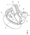
- Figure 3 shows a perspective view of the nose 10.
- Figure 4 shows another perspective view of the casing bit 1 of Figure 1 .
- the body 5 may be tubular shaped having one end adapted for connection with the nose 10, for example, using a threaded connection, adhesive, or weld.
- the other end may have threads for connection with a bottom of a casing or liner string (not shown) or a casing adapter having a pin or box for connection with the casing or liner bottom.
- the nose 10 may be attached to the body 5 using a weld or locking members such pins or screws.
- Stabilizers 25 may be formed on the outer surface of the body 5.
- the stabilizers 25 may optionally include recesses 27 for receiving an insert.
- the outer surface of the body 5 also includes profiles 21 for attachment with the blades 15.
- a port 57 having a shearable member such as rupture disc may be provided on the body 5 as illustrated in Figure 7A .
- the body 5 is made from any suitable material that provides suitable mechanical properties to substantially complement those of the casing to liner to which the body is attached, for example, steel.
- the stabilizers 25 may extend longitudinally and/or helically along the body 5.
- the stabilizers 25 may be formed integrally or attached to the body 5.
- the stabilizers 25 may be made from the same material as the body 5.
- the stabilizers 25 may be aligned with the blades 15.
- An outer surface of the stabilizers 25 may extend outward past the gage portion of each blade 15.
- Inserts 28, such as buttons (shown in Figures 1 and 4 ), may be disposed along an outer surface of each of the stabilizers 25.
- the inserts .28 may be made from a wear-resistant material, such as a ceramic or cermet (i.e., tungsten carbide), diamond (i.e., PDC), or any suitable wear-resistant material.
- the inserts 28 may be brazed, welded, or pressed into recesses 27 formed in the outer surface of the stabilizers 25 so that the buttons are flush with or extend outward past the stabilizer outer surface.
- the wear resistant carbide buttons could also be welded-on hardfacing material.
- the nose 10 may include a threaded portion 12 for attachment to the body 5.
- the face 16 of the nose 10 above the threaded portion 12 may have a larger diameter than the threaded portion 12.
- a plurality of blade supports 14 may be formed on the face 16 of the nose 10.
- the blade supports 14 are configured to receive a respective blade 15 thereon.
- the blade supports 14 are raised portions on the face 16.
- the blade supports 14 may be formed integrally such as by casting, machining, or attached by weld to the nose 10.
- the blade supports 14 may each extend radially or helically to a center of the face 16.
- the blade supports 14 may extend radially or helically to a substantial distance toward the face center, such as greater than or equal to one-third or one-half the radius of the nose 10.
- a height of the blade supports 14 may decrease as the blade supports extend from the side toward the center of the face 16.
- the nose 10, including the blade supports 14, may be made from a drillable material, for example, metal or alloy such as aluminum, or a composite such as cermet.
- the face 16 should have sufficient thickness to counter weight on bit deflections during the drilling operation, as shown in Figure 7A .
- the face 16 may have a thickness of at least one inch, preferably between 1 and 2 inches.
- at least 50% by weight of the nose 10 is made of aluminum; preferably, at least 75% by weight is made of aluminum; and more preferably, at least 90% by weight of the nose 10 is made of aluminum.
- Other suitable drillable material include any material which has sufficient structural strength to support the loads applied to the blades during use of the earth removal member, but also which has properties suitable for subsequent removal by a standard drill bit.
- the nose 10 may be made of a composite such as glass/epoxy or a plastic material.
- the face portion 16 of the nose 10 has an aluminum cross-section.
- the inner surface of the nose 10 may be profiled with a curvature or flat.
- the drillable material allows the nose 10 to be drilled through and the body 5 to remain after drill/mill-through.
- the face 16 may be drilled through after cementing the casing and the casing bit into the wellbore.
- the blade supports 14 may include a profile 31 for mating with a blade 15.
- the profile 31 is formed on an upper surface of the blade support 14.
- the profile 31 includes a floor surface 34 having a protrusion and a side wall surface 36.
- the protrusion may be formed on the side wall surface 36 or both surfaces 34, 36.
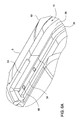
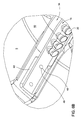
- FIGS 5 and 5A-D are different perspective views of an exemplary blade 15.
- the blade 15 may have a mating profile 43 for attachment with the profile 31 on the blade support 14. As shown, the profile 43 extends along the entire length of the blade 15, which includes a cutter portion 41 and a body portion 42. As shown, the blade profile 43 includes a back wall 46 for mating with the side wall surface 36. Also, the blade profile 43 includes a lower surface 44 having a groove for mating with the protrusion of the blade support 14. It is contemplated that the protrusion may be formed on the blade 15, while the groove is formed on the blade support 14. In one embodiment, the blade 15 is shaped to conform to the overall shape of the blade supports 14.
- the blade 15 may remain in position relying only on its overall shape and the mating profiles 31, 43.
- an adhesive may be used to attach the blade 15 to the blade support 14.
- the body portion 42 may include holes 48 for receiving a pin or screw to attach the blade 15 to the body 5.
- the cutter portion 41 includes a plurality of recesses 47 (shown in Figure 5B ) for receiving a plurality of cutters 20, as shown in Figures 5 and 5D .
- the cutters 20 may be bonded into respective recesses 47 formed along each blade 15.
- the cutters 20 may be made from a super-hard material, such as polycrystalline diamond compact (PDC), natural diamond, or cubic boron nitride.
- the PDC may be conventional, cellular, or thermally stable (TSP).
- TSP thermally stable
- the cutters 20 may be bonded into the recesses 47, such as by brazing, welding, soldering, press fitting, using an adhesive, and combinations thereof.
- the cutters 20 may be disposed along each blade 15 and be located in both gage and face portions of each blade.
- the blades 15 may be omitted and the cutters 20 may be disposed directly in the blade support 14 and/or the nose 10, such as in the face 16 and/or the side.
- the blades include a wear resistant coating.
- the blades may be sprayed with a coating of HVOF ("high velocity oxygen fuel") to increase the erosion resistance of the blades.
- FIGS 6A-B are enlarged partial views of the body 5 before (6A) and after (6B) attachment of the blades 15.
- the blades 15 may be made of steel and attached to the body 5 by welding.
- An exemplary steel material for the blades 15 is low yield steel.
- the blade is made of cast iron.
- the blade 15 is first secured to the body 5 by inserting a cap screw 49 through the blade 15 and into a hole 48 in the body 5. Then, the blade is welded to the body 5.
- the profile on the body 5 for receiving the blade 15 may have pockets 53 for accommodating the weld material connecting the blade 15 to the body 5. After welding, the cap screw 49 is optionally removed.
- the blades may also be attached by wedging into a groove on the side of the body. In this configuration, the blades would be wedged tighter to the body upon application of weight on bit.
- the blades 15 may be bonded or otherwise attached to the blade supports 14, such as by brazing, soldering, or using an adhesive.
- the blades may be made from a drillable material, such as a nonferrous metal or alloy (i.e., copper, brass, bronze, aluminum, zinc, tin, or alloys thereof), a polymer, or composite.
- Figures 7A-B illustrate another embodiment of an earth removal member.
- Figure 7A is a cross-sectional view of the earth removal member
- Figure 7B is an end view of the earth removal member.
- the earth removal member 80 includes a nose 10 connected to a body 5.
- the body 5 includes stabilizers 25 having an insert 28 attached thereto, and a port 57 initially blocked using a shearable member.
- a plurality of nozzles 30 are disposed in the nose 16 and may be arranged in any suitable manner.
- a plurality of blade supports 14 extends from the face 16 and configured to receive a blade 15.
- the blade support 14 and the blade 15 may have mating profiles 31, 43 to facilitate engagement of the blade 15 to the blade support 14.
- Figure 8 shows the casing bit 1 of Figure 1 after it has been drilled out by a subsequent drill bit.
- the subsequent drill bit may be another casing bit.
- the drill out path 58 of the subsequent drill bit is shown just beyond the drilled out casing bit 1.
- the remainder of the casing bit 1 includes an inner diameter that is substantially equal to the bore of the body 5.
- the nose 10 is axially fixed relative to the body 5 due to the threaded connection between the nose 10 and the body 5.
- the blade bonding process allows the blades 15 to remain attached to the blade support 14. In this respect, the blades 15 remains substantially intact until they are broken into smaller pieces by the subsequent drill bit.
- the mass removed from the casing bit 1 may include more than 75% by weight of aluminum; preferably, more than 90% by weight of aluminum; and more preferably, more than 95% by weight of aluminum.
- the steel from the blade makes up a majority of the steel removed, which may be less than 15% by weight of the total mass removed; preferably, less than 5% by weight.
- Figure 9A shows a partial cross-sectional view of another embodiment of a casing bit 101.
- an optional seal 61 is provided between the nose 10 and the body 5 to prevent a fluid leak path to the exterior of the casing bit 101.
- the nose 10 may include a plurality of nozzles 30 disposed in a plurality of fluid channels in the nose 10. A portion of the nozzle 30 may protrude out of the nose 10 and extend into an interior space of the casing bit 101.
- the fluid channels could also be port holes for directing fluid.
- the casing bit may have a combination of port holes and nozzles.
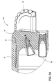
- Figure 9B shows a partial cross-sectional view of another embodiment of a casing bit 121.
- An optional seal 61 is provided between the nose 10 and the body 5 to prevent a fluid leak path to the exterior of the casing bit 121.
- the nose 10 may include a plurality of nozzles 130 disposed in a plurality of fluid channels 135 in the nose 10.
- Each nozzle 130 may include a flow tube 131 disposed in the fluid channel 135 and a retainer 132 for retaining the flow tube in the fluid channel.
- the retainer 132 may be threadedly connected to the channel 135 to retain nozzle 130 in the channel 135. In this respect, the nozzle 130 is mechanically retained in the fluid channel 135.
- a portion of the flow tube 131 may protrude out of the nose 10 and extend into an interior space of the casing bit 121.
- the bore inside flow tube may have a smaller inner diameter near the exit, as shown, a constant inner diameter, or a larger inner diameter near the exit.
- the flow tube may have an outer shoulder for engaging a shoulder to the fluid channel 135.
- the fluid channels could also be port holes for directing fluid.
- the casing bit may have a combination of port holes and nozzles.
- the nose 210 of the casing bit 201 may have an outer diameter that is sized to fit within the body 205, as shown in Figure 10 .
- the front end 205A of the body 205 may extend beyond the threads 222 and surround the perimeter of the nose 210.
- the steel body 205, 205A surrounding the nose 210 provides added strength to the casing bit 201.
- the front end 205A has an inner diameter larger than the outer diameter of the subsequent drill-out bit so that it would not interfere with the drill out operation. Because the outer diameter of the nose 210 is still larger than the size of the subsequent drill bit, the nose 210 is still suitable for drill through.
- Figure 10A is a bottom view of the nose 210 surrounded by the body 205.
- the body 205 may be made from any suitable material that provides suitable mechanical properties to substantially complement those of the casing to liner to which the body is attached, for example, steel.
- the nose 210 may be made from any suitable drillable material which has sufficient structural strength to support the loads applied to the blades during use of the earth removal member, but also which has properties suitable for subsequent removal by a standard drill bit.
- the blades 15 may be locked to the blade support 14 using one or more secondary locking members such as pins, screws, or nails.
- the locking pins 51 may be used in addition to a bonding process such as welding.
- the pins 51 may be inserted through the blade support 14 and the blade 15. As shown, the pins 51 are disposed through the side wall of the blade support 14 and the blade 15.
- the pins 51 prevent the blades 15 from being separated from the nose 10 during drill out.
- the mating profiles 31, 43 between the blades 15 and the blade support 14 prevent the blades 15 from separating from the nose 10 during backward rotation of the blades 15. In this respect, the mating profiles and the locking members allow the casing bit to rotate in either direction.
- the pins may be made of a drillable material such as aluminum.
- the pins 52 may be inserted through the blades 15 and then into the floor surface of the blade support 14.
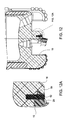
- Figure 12A is an enlarged partial view of Figure 12 .
- the mating profiles 54 are formed between the blade 15 and the side wall of the blade support 14.
- the pins 52 serve to prevent displacement of the blade 15 during backward rotation of the blades 15, while the profiles 54 prevent the blade 15 from separating from the blade support 14 during drill out.
- a combination of pins and mating profiles may be used to prevent the blades 15 from separating during operation.
- pins 51, 52 may be separately inserted through the sidewall and the blades, and optionally, a mating groove profiles may be used.
- the mating profiles and the locking members allow the casing bit to rotate in either direction.
- the blades may be attached to the blade support using only the secondary locking members.
- the mating profiles and the secondary locking members allow coupling of the blade to the blade support without permanently fixing the blade to the blade support.
- the blade may optionally be fixed such as by welding to the blade support.
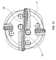
- two or more blades 15A, B on the nose 10 may be connected to each other to provide additional support against separation during operation, as shown in Figure 13 .
- the ends of two blades 15A, B near the center of the nose 10 may be welded together.
- the blades may be connected using an interlocking connection such as mating grooves, pins, dove tails, or other suitable mechanical locking devices or bonding methods.
- these locking or bonding devices or methods assist with maintaining the blades 15 in position during drill out. In this respect, the blades 15 are prevented from premature separation or breaking until it is broken into smaller pieces by direct contact with the drill-out bit.
Landscapes
- Engineering & Computer Science (AREA)
- Life Sciences & Earth Sciences (AREA)
- Geology (AREA)
- Mining & Mineral Resources (AREA)
- Mechanical Engineering (AREA)
- Physics & Mathematics (AREA)
- Environmental & Geological Engineering (AREA)
- Fluid Mechanics (AREA)
- General Life Sciences & Earth Sciences (AREA)
- Geochemistry & Mineralogy (AREA)
- Earth Drilling (AREA)
Description
- This application claims benefit of
U.S. Provisional Patent Application Serial No. 61/459,969, filed December 22, 2010 - Embodiments of the present invention generally relate to an earth removal member with features for facilitating subsequent drill-through.
- The drilling of wellbores for oil and gas production conventionally employs strings of drill pipe to which, at one end, is secured a drill bit. After a selected portion of the wellbore has been drilled, the wellbore is usually cased with a string of casing or lined with a string of liner. Drilling and casing/lining according to the conventional process typically requires sequentially drilling the wellbore using drill string with a drill bit attached thereto, removing the drill string and drill bit from the wellbore, and disposing casing/lining into the wellbore. Further, often after a section of the borehole cased/lined, which is usually cemented into place, additional drilling beyond the end of the casing/liner may be desired.
- Unfortunately, sequential drilling and casing may be time consuming because, as may be appreciated, at the considerable depths reached during oil and gas production, the time required to retrieve the drill string may be considerable. Thus, such operations may be costly as well due to the high cost of rig time. Moreover, control of the well may be difficult during the period of time that the drill pipe is being removed and the casing/lining is being disposed into the borehole.
- Some approaches have been developed to address the difficulties associated with conventional drilling and casing/lining operations. Of initial interest is an apparatus which is known as a reaming casing shoe that has been used in conventional drilling operations. Reaming casing shoes have become available relatively recently and are devices that are able to drill through modest obstructions within a borehole that has been previously drilled.
- As a further extension of the reaming casing shoe concept, in order to address the problems with sequential drilling and casing, drilling with casing/liner is gaining popularity as a method for drilling a wellbore, wherein the casing/liner is used as the drill string and, after drilling, the casing/liner remains downhole to line the wellbore. Drilling with casing/liner employs a drill bit attached to the casing/liner string, so that the drill bit functions not only to drill the earth formation, but also to guide the casing/liner into the wellbore. This may be advantageous as the casing/liner is disposed into the wellbore as it is formed by the drill bit, and therefore eliminates the necessity of retrieving the drill string and drill bit after reaching a target depth where cementing is desired.
- While this procedure greatly increases the efficiency of the drilling procedure, a further problem is encountered when the casing/liner is cemented upon reaching the desired depth. While one advantage of drilling with casing is that the drill bit does not have to be retrieved from the wellbore, further drilling may be required. Thus, further drilling must pass through the drill bit attached to the end of the casing/liner.
WO2004076804 recites a method and apparatus for later drilling through. - However, drilling through the casing/liner drill bit may be difficult as drill bits are required to remove rock from formations and accordingly often include very drilling resistant, robust structures typically manufactured from hard or super-hard materials. Attempting to drill through a drill bit affixed to the end of a casing/liner may result in damage to the subsequent drill bit and bottom-hole assembly deployed or possibly the casing/liner itself. It may be possible to drill through a drill bit or a casing with special tools known as mills, but these tools are unable to penetrate rock formations effectively and the mill would have to be retrieved or "tripped" from the wellbore and replaced with a drill bit. In this case, the time and expense saved by drilling with casing would be mitigated or even lost.
- The present invention generally relates to an earth removal member with features for facilitating subsequent drill-through. In one aspect of the present invention, the earth removal member comprises a tubular body; a nose attached to one end of the tubular body, wherein the nose includes a blade support and comprises a drillable material; a blade attached to the blade support using mating profiles; cutters disposed along the blade; a nozzle disposed in the nose and a locking member disposed in the blade support and the blade. The blade support is a raised portion on a face of the nose.
- In another embodiment, the earth removal member includes a pin disposed in the blade support and the blade. In yet another embodiment, at least two blades are connected to each other. In still yet another embodiment, at least a face portion of the nose has an aluminum cross-section. Further preferred embodiments are described in the dependent claims.
- In another aspect of the present invention, a method of removing or partially removing an earth removal member includes providing the earth removal member with a tubular body; a nose attached to one end of the tubular body, wherein the nose includes a blade support and comprises a drillable material; a blade attached to the nose using mating profiles; cutters disposed along the blade and a locking member disposed in the blade support and the blade. The blade support is a raised portion on a face of the nose. The method also includes positioning a drill bit in the tubular body; rotating the drill bit against an interior surface of the nose; removing a portion of the nose while the blade is substantially attached to the nose; and rotating the drill bit against the blade, thereby breaking the blade into smaller pieces. In another embodiment, the nose may remain axially fixed to the tubular body during drill out.
- So that the manner in which the above recited features of the present invention can be understood in detail, a more particular description of the invention, briefly summarized above, may be had by reference to embodiments, some of which are illustrated in the appended drawings. It is to be noted, however, that the appended drawings illustrate only typical embodiments of this invention.
-
Figure 1 is a perspective view of an embodiment of an earth removal member. -
Figure 2 shows a perspective view of thebody 5 of the earth removal member ofFigure 1 . -
Figure 3 shows a perspective view of thenose 10 of the earth removal member ofFigure 1 . -
Figure 4 shows another embodiment of the earth removal member. -
Figures 5 and 5A-D are different perspective views of an exemplary blade of the earth removal member ofFigure 1 . -
Figures 6A-B are perspective views of an exemplary body and a blade attached to the body. -
Figure 7A is a cross-sectional view of another embodiment of an exemplary earth removal member.Figure 7B is an end view of the earth removal member. -
Figure 8 shows an earth removal member after it has been drilled through. -
Figure 9A shows a partial cross-sectional view of another embodiment of an earth removal member. -
Figure 9B shows another partial cross-sectional view of another embodiment of an earth removal member.Figure 9C is a partial end view of the earth removal member ofFigure 9B . -
Figures 10 and10A show another embodiment of an earth removal member. -
Figure 11 shows an exemplary earth removal member having secondary locking members to retain the blades. -
Figure 12 shows another embodiment of locking the blades to an earth removal member.Figure 12A is an enlarged partial view ofFigure 12 . -
Figure 13 shows an embodiment an earth removal member having two blades connected together. -
Figure 1 is a perspective view of an earth removal member, such as acasing bit 1, according to one embodiment of the present invention. Alternatively, the earth removal member may be a drill bit, reamer shoe, a pilot bit, a core bit, or a hammer bit. Thecasing bit 1 may include abody 5, anose 10, one ormore blades 15, one ormore cutters 20, one ormore stabilizers 25, and one ormore nozzles 30.Figure 2 shows a perspective view of thebody 5.Figure 3 shows a perspective view of thenose 10.Figure 4 shows another perspective view of thecasing bit 1 ofFigure 1 . - Referring to
Figure 2 , thebody 5 may be tubular shaped having one end adapted for connection with thenose 10, for example, using a threaded connection, adhesive, or weld. The other end may have threads for connection with a bottom of a casing or liner string (not shown) or a casing adapter having a pin or box for connection with the casing or liner bottom. In another embodiment, thenose 10 may be attached to thebody 5 using a weld or locking members such pins or screws.Stabilizers 25 may be formed on the outer surface of thebody 5. Thestabilizers 25 may optionally includerecesses 27 for receiving an insert. The outer surface of thebody 5 also includesprofiles 21 for attachment with theblades 15. Aport 57 having a shearable member such as rupture disc may be provided on thebody 5 as illustrated inFigure 7A . Thebody 5 is made from any suitable material that provides suitable mechanical properties to substantially complement those of the casing to liner to which the body is attached, for example, steel. - The
stabilizers 25 may extend longitudinally and/or helically along thebody 5. Thestabilizers 25 may be formed integrally or attached to thebody 5. Thestabilizers 25 may be made from the same material as thebody 5. Thestabilizers 25 may be aligned with theblades 15. An outer surface of thestabilizers 25 may extend outward past the gage portion of eachblade 15.Inserts 28, such as buttons (shown inFigures 1 and4 ), may be disposed along an outer surface of each of thestabilizers 25. The inserts .28 may be made from a wear-resistant material, such as a ceramic or cermet (i.e., tungsten carbide), diamond (i.e., PDC), or any suitable wear-resistant material. Theinserts 28 may be brazed, welded, or pressed intorecesses 27 formed in the outer surface of thestabilizers 25 so that the buttons are flush with or extend outward past the stabilizer outer surface. In one embodiment, the wear resistant carbide buttons could also be welded-on hardfacing material. - As shown in
Figure 3 , thenose 10 may include a threadedportion 12 for attachment to thebody 5. Theface 16 of thenose 10 above the threadedportion 12 may have a larger diameter than the threadedportion 12. A plurality of blade supports 14 may be formed on theface 16 of thenose 10. The blade supports 14 are configured to receive arespective blade 15 thereon. In one embodiment, the blade supports 14 are raised portions on theface 16. The blade supports 14 may be formed integrally such as by casting, machining, or attached by weld to thenose 10. The blade supports 14 may each extend radially or helically to a center of theface 16. For example, the blade supports 14 may extend radially or helically to a substantial distance toward the face center, such as greater than or equal to one-third or one-half the radius of thenose 10. A height of the blade supports 14 may decrease as the blade supports extend from the side toward the center of theface 16. - The
nose 10, including the blade supports 14, may be made from a drillable material, for example, metal or alloy such as aluminum, or a composite such as cermet. Theface 16 should have sufficient thickness to counter weight on bit deflections during the drilling operation, as shown inFigure 7A . For example, theface 16 may have a thickness of at least one inch, preferably between 1 and 2 inches. In one embodiment, at least 50% by weight of thenose 10 is made of aluminum; preferably, at least 75% by weight is made of aluminum; and more preferably, at least 90% by weight of thenose 10 is made of aluminum. Other suitable drillable material include any material which has sufficient structural strength to support the loads applied to the blades during use of the earth removal member, but also which has properties suitable for subsequent removal by a standard drill bit. In one embodiment, thenose 10 may be made of a composite such as glass/epoxy or a plastic material. In an exemplary embodiment, theface portion 16 of thenose 10 has an aluminum cross-section. The inner surface of thenose 10 may be profiled with a curvature or flat. The drillable material allows thenose 10 to be drilled through and thebody 5 to remain after drill/mill-through. Theface 16 may be drilled through after cementing the casing and the casing bit into the wellbore. - Referring back to
Figures 3 and4 , the blade supports 14 may include aprofile 31 for mating with ablade 15. In one embodiment, theprofile 31 is formed on an upper surface of theblade support 14. Theprofile 31 includes afloor surface 34 having a protrusion and aside wall surface 36. In another embodiment, the protrusion may be formed on theside wall surface 36 or bothsurfaces -
Figures 5 and 5A-D are different perspective views of anexemplary blade 15. Theblade 15 may have amating profile 43 for attachment with theprofile 31 on theblade support 14. As shown, theprofile 43 extends along the entire length of theblade 15, which includes acutter portion 41 and abody portion 42. As shown, theblade profile 43 includes aback wall 46 for mating with theside wall surface 36. Also, theblade profile 43 includes alower surface 44 having a groove for mating with the protrusion of theblade support 14. It is contemplated that the protrusion may be formed on theblade 15, while the groove is formed on theblade support 14. In one embodiment, theblade 15 is shaped to conform to the overall shape of the blade supports 14. In this respect, theblade 15 may remain in position relying only on its overall shape and the mating profiles 31, 43. Alternatively, an adhesive may be used to attach theblade 15 to theblade support 14. Thebody portion 42 may includeholes 48 for receiving a pin or screw to attach theblade 15 to thebody 5. - The
cutter portion 41 includes a plurality of recesses 47 (shown inFigure 5B ) for receiving a plurality ofcutters 20, as shown inFigures 5 and 5D . Thecutters 20 may be bonded intorespective recesses 47 formed along eachblade 15. Thecutters 20 may be made from a super-hard material, such as polycrystalline diamond compact (PDC), natural diamond, or cubic boron nitride. The PDC may be conventional, cellular, or thermally stable (TSP). Thecutters 20 may be bonded into therecesses 47, such as by brazing, welding, soldering, press fitting, using an adhesive, and combinations thereof. Thecutters 20 may be disposed along eachblade 15 and be located in both gage and face portions of each blade. Alternatively, theblades 15 may be omitted and thecutters 20 may be disposed directly in theblade support 14 and/or thenose 10, such as in theface 16 and/or the side. In another embodiment, the blades include a wear resistant coating. For example, the blades may be sprayed with a coating of HVOF ("high velocity oxygen fuel") to increase the erosion resistance of the blades. -
Figures 6A-B are enlarged partial views of thebody 5 before (6A) and after (6B) attachment of theblades 15. Theblades 15 may be made of steel and attached to thebody 5 by welding. An exemplary steel material for theblades 15 is low yield steel. In another example, the blade is made of cast iron. Referring now toFigures 6A-B , theblade 15 is first secured to thebody 5 by inserting acap screw 49 through theblade 15 and into ahole 48 in thebody 5. Then, the blade is welded to thebody 5. The profile on thebody 5 for receiving theblade 15 may havepockets 53 for accommodating the weld material connecting theblade 15 to thebody 5. After welding, thecap screw 49 is optionally removed. In another embodiment, the blades may also be attached by wedging into a groove on the side of the body. In this configuration, the blades would be wedged tighter to the body upon application of weight on bit. Alternatively, theblades 15 may be bonded or otherwise attached to the blade supports 14, such as by brazing, soldering, or using an adhesive. In this alternative, the blades may be made from a drillable material, such as a nonferrous metal or alloy (i.e., copper, brass, bronze, aluminum, zinc, tin, or alloys thereof), a polymer, or composite. -
Figures 7A-B illustrate another embodiment of an earth removal member.Figure 7A is a cross-sectional view of the earth removal member, andFigure 7B is an end view of the earth removal member. As shown, theearth removal member 80 includes anose 10 connected to abody 5. Thebody 5 includesstabilizers 25 having aninsert 28 attached thereto, and aport 57 initially blocked using a shearable member. A plurality ofnozzles 30 are disposed in thenose 16 and may be arranged in any suitable manner. A plurality of blade supports 14 extends from theface 16 and configured to receive ablade 15. Theblade support 14 and theblade 15 may havemating profiles blade 15 to theblade support 14. -
Figure 8 shows thecasing bit 1 ofFigure 1 after it has been drilled out by a subsequent drill bit. The subsequent drill bit may be another casing bit. The drill outpath 58 of the subsequent drill bit is shown just beyond the drilled outcasing bit 1. It can be seen that the remainder of thecasing bit 1 includes an inner diameter that is substantially equal to the bore of thebody 5. Also, during drill-out of thenose 10, thenose 10 is axially fixed relative to thebody 5 due to the threaded connection between thenose 10 and thebody 5. Further, the blade bonding process allows theblades 15 to remain attached to theblade support 14. In this respect, theblades 15 remains substantially intact until they are broken into smaller pieces by the subsequent drill bit. In can be seen that portions of theblades 15 outside of the drill outpath 58 may remain attached to thebody 5 or thenose 10. In one embodiment, the mass removed from thecasing bit 1 may include more than 75% by weight of aluminum; preferably, more than 90% by weight of aluminum; and more preferably, more than 95% by weight of aluminum. The steel from the blade makes up a majority of the steel removed, which may be less than 15% by weight of the total mass removed; preferably, less than 5% by weight. -
Figure 9A shows a partial cross-sectional view of another embodiment of acasing bit 101. In this embodiment, anoptional seal 61 is provided between thenose 10 and thebody 5 to prevent a fluid leak path to the exterior of thecasing bit 101. Thenose 10 may include a plurality ofnozzles 30 disposed in a plurality of fluid channels in thenose 10. A portion of thenozzle 30 may protrude out of thenose 10 and extend into an interior space of thecasing bit 101. In another embodiment, the fluid channels could also be port holes for directing fluid. In yet another embodiment, the casing bit may have a combination of port holes and nozzles. -
Figure 9B shows a partial cross-sectional view of another embodiment of acasing bit 121. Anoptional seal 61 is provided between thenose 10 and thebody 5 to prevent a fluid leak path to the exterior of thecasing bit 121. Thenose 10 may include a plurality ofnozzles 130 disposed in a plurality offluid channels 135 in thenose 10. Eachnozzle 130 may include aflow tube 131 disposed in thefluid channel 135 and aretainer 132 for retaining the flow tube in the fluid channel. Theretainer 132 may be threadedly connected to thechannel 135 to retainnozzle 130 in thechannel 135. In this respect, thenozzle 130 is mechanically retained in thefluid channel 135. A portion of theflow tube 131 may protrude out of thenose 10 and extend into an interior space of thecasing bit 121. In one embodiment, the bore inside flow tube may have a smaller inner diameter near the exit, as shown, a constant inner diameter, or a larger inner diameter near the exit. In another embodiment, the flow tube may have an outer shoulder for engaging a shoulder to thefluid channel 135. In another embodiment, the fluid channels could also be port holes for directing fluid. In yet another embodiment, the casing bit may have a combination of port holes and nozzles. - In another embodiment, the
nose 210 of thecasing bit 201 may have an outer diameter that is sized to fit within thebody 205, as shown inFigure 10 . Thefront end 205A of thebody 205 may extend beyond thethreads 222 and surround the perimeter of thenose 210. Thesteel body nose 210 provides added strength to thecasing bit 201. However, thefront end 205A has an inner diameter larger than the outer diameter of the subsequent drill-out bit so that it would not interfere with the drill out operation. Because the outer diameter of thenose 210 is still larger than the size of the subsequent drill bit, thenose 210 is still suitable for drill through.Figure 10A is a bottom view of thenose 210 surrounded by thebody 205. Thebody 205 may be made from any suitable material that provides suitable mechanical properties to substantially complement those of the casing to liner to which the body is attached, for example, steel. Thenose 210 may be made from any suitable drillable material which has sufficient structural strength to support the loads applied to the blades during use of the earth removal member, but also which has properties suitable for subsequent removal by a standard drill bit. - As shown in
Figure 11 , theblades 15 may be locked to theblade support 14 using one or more secondary locking members such as pins, screws, or nails. The locking pins 51 may be used in addition to a bonding process such as welding. Thepins 51 may be inserted through theblade support 14 and theblade 15. As shown, thepins 51 are disposed through the side wall of theblade support 14 and theblade 15. Thepins 51 prevent theblades 15 from being separated from thenose 10 during drill out. The mating profiles 31, 43 between theblades 15 and theblade support 14 prevent theblades 15 from separating from thenose 10 during backward rotation of theblades 15. In this respect, the mating profiles and the locking members allow the casing bit to rotate in either direction. The pins may be made of a drillable material such as aluminum. - Alternatively, as shown in
Figure 12 , thepins 52 may be inserted through theblades 15 and then into the floor surface of theblade support 14.Figure 12A is an enlarged partial view ofFigure 12 . As shown, the mating profiles 54 are formed between theblade 15 and the side wall of theblade support 14. In this embodiment, thepins 52 serve to prevent displacement of theblade 15 during backward rotation of theblades 15, while theprofiles 54 prevent theblade 15 from separating from theblade support 14 during drill out. It is contemplated that a combination of pins and mating profiles may be used to prevent theblades 15 from separating during operation. For example, pins 51, 52 may be separately inserted through the sidewall and the blades, and optionally, a mating groove profiles may be used. In this respect, the mating profiles and the locking members allow the casing bit to rotate in either direction. In yet another embodiment, the blades may be attached to the blade support using only the secondary locking members. The mating profiles and the secondary locking members allow coupling of the blade to the blade support without permanently fixing the blade to the blade support. However, it is contemplated that the blade may optionally be fixed such as by welding to the blade support. - In another embodiment, two or
more blades 15A, B on thenose 10 may be connected to each other to provide additional support against separation during operation, as shown inFigure 13 . For example, the ends of twoblades 15A, B near the center of thenose 10 may be welded together. Alternatively, the blades may be connected using an interlocking connection such as mating grooves, pins, dove tails, or other suitable mechanical locking devices or bonding methods. One or more of these locking or bonding devices or methods assist with maintaining theblades 15 in position during drill out. In this respect, theblades 15 are prevented from premature separation or breaking until it is broken into smaller pieces by direct contact with the drill-out bit. - While the foregoing is directed to embodiments of the present invention, other and further embodiments of the invention may be devised without departing from the scope of the invention which is defined according to the wording of the appended claims.
Claims (16)
- An earth removal member (1,80,101,121,201) for drilling a wellbore with casing or liner, comprising:a tubular body (5,205);a nose (10,210) attached to one end of the tubular body, wherein the nose includes a blade support (14) and comprises a drillable material;a blade (15,15A,15B) attached to the blade support using mating profiles (31,43,54);cutters (20) disposed along the blade; anda nozzle (30,130) disposed in the nose;characterised in that the blade support is a raised portion on a face (16) of the nose and in that a locking member (51,52) is disposed in the blade support and the blade.
- The earth removal member of claim 1, wherein the locking member is inserted through the blade support.
- The earth removal member of claim 1 or 2, wherein the mating profiles include a recess formed on the blade and a protrusion formed on the blade support.
- The earth removal member of claim 3, wherein the mating profiles prevent the blade from separating from the nose during backward rotation of the blades.
- The earth removal member of claim 1 or 2, wherein the mating profiles include a recess formed on the blade support and a protrusion formed on the blade.
- The earth removal member of claim 5, wherein the mating profiles prevent the blade from separating from the blade support during drill out.
- The earth removal member of claim 1, wherein the locking member is inserted through the blade.
- The earth removal member of any preceding claim, wherein at least 50% of the nose comprises aluminium.
- The earth removal member of any preceding claim, wherein the blade comprises low yield steel or cast iron.
- The earth removal member of any preceding claim, wherein at least a face portion of the nose has an aluminium cross-section.
- The earth removal member of claim 10, wherein the blade support comprises aluminium.
- The earth removal member of any preceding claim, wherein at least a portion of the nose is disposed within the tubular body.
- The earth removal member of any preceding claim, wherein two blades are connected to each other.
- The earth removal member of any preceding claim, wherein the nozzle is retained in the nose using a mechanical device.
- A method of removing an earth removal member (1,80,101,121,201), comprising:providing the earth removal member with:a tubular body (5,205);a nose (10,210) attached to one end of the tubular body, wherein the nose includes a blade support (14) and comprises a drillable material;a blade (15,15A,15B) attached to the nose using mating profiles (31,43,54); andcutters (20) disposed along the blade;positioning a drill bit in the tubular body;rotating the drill bit against an interior surface of the nose;removing a portion of the nose while the blade is substantially attached to the nose; androtating the drill bit against the blade, thereby breaking the blade into smaller pieces;characterised in that the blade support (14) is a raised portion on a face (16) of the nose (10, 210) and in that the method further comprises providing the earth removal member with a locking member (51,52) disposed in the blade support and the blade.
- The method of claim 15, wherein the nose remains axially fixed to the tubular body during drill out.
Applications Claiming Priority (2)
| Application Number | Priority Date | Filing Date | Title |
|---|---|---|---|
| US201061459969P | 2010-12-22 | 2010-12-22 | |
| PCT/US2011/066607 WO2012088323A2 (en) | 2010-12-22 | 2011-12-21 | Earth removal member with features for facilitating drill-through |
Publications (2)
| Publication Number | Publication Date |
|---|---|
| EP2655784A2 EP2655784A2 (en) | 2013-10-30 |
| EP2655784B1 true EP2655784B1 (en) | 2016-11-16 |
Family
ID=45491816
Family Applications (1)
| Application Number | Title | Priority Date | Filing Date |
|---|---|---|---|
| EP11808800.4A Not-in-force EP2655784B1 (en) | 2010-12-22 | 2011-12-21 | Earth removal member with features for facilitating drill-through |
Country Status (6)
| Country | Link |
|---|---|
| US (1) | US8960332B2 (en) |
| EP (1) | EP2655784B1 (en) |
| AU (1) | AU2011348242B2 (en) |
| CA (1) | CA2820954C (en) |
| DK (1) | DK2655784T3 (en) |
| WO (1) | WO2012088323A2 (en) |
Families Citing this family (11)
| Publication number | Priority date | Publication date | Assignee | Title |
|---|---|---|---|---|
| US9982490B2 (en) * | 2013-03-01 | 2018-05-29 | Baker Hughes Incorporated | Methods of attaching cutting elements to casing bits and related structures |
| FR3020089A1 (en) * | 2014-04-18 | 2015-10-23 | Entpr De Travaux Publics De L Ouest | DEVICE FOR DRILLING THE GENUS TREPAN EMULSEUR |
| US10428584B2 (en) | 2016-07-13 | 2019-10-01 | Varel International Ind., L.P. | Bit for drilling with casing or liner string and manufacture thereof |
| WO2018034657A1 (en) * | 2016-08-17 | 2018-02-22 | Halliburton Energy Services Inc. | Modular reaming device |
| RU2769361C2 (en) | 2017-05-31 | 2022-03-30 | Смит Интернэшнл, Инк. | Cutting tool with pre-formed segments with hard-facing |
| US10487590B2 (en) | 2017-07-28 | 2019-11-26 | Baker Hughes, A Ge Company, Llc | Cutting element assemblies and downhole tools comprising rotatable cutting elements and related methods |
| CN107558929A (en) * | 2017-10-17 | 2018-01-09 | 沧州格锐特钻头有限公司 | A kind of special type refuses mud drum PDC drill bit |
| CN111456024A (en) * | 2020-04-07 | 2020-07-28 | 石家庄学院 | Rock-socketed secant pile construction method for rockfill stratum |
| BE1028279B1 (en) | 2020-05-08 | 2021-12-07 | Diamant Drilling Services S A | TREPAN |
| WO2022047017A1 (en) | 2020-08-27 | 2022-03-03 | Schlumberger Technology Corporation | Blade cover |
| CN118242030B (en) * | 2024-05-28 | 2024-07-19 | 山东省地质矿产勘查开发局第三地质大队(山东省第三地质矿产勘查院、山东省海洋地质勘查院) | Device for eliminating scaling of drill rod for rope coring drilling |
Citations (1)
| Publication number | Priority date | Publication date | Assignee | Title |
|---|---|---|---|---|
| US2693938A (en) * | 1952-08-01 | 1954-11-09 | Harry E Roberts | Drilling bit |
Family Cites Families (55)
| Publication number | Priority date | Publication date | Assignee | Title |
|---|---|---|---|---|
| US1388490A (en) | 1920-09-18 | 1921-08-23 | John R Suman | Rotary earth-boring drill |
| US1586415A (en) * | 1923-11-01 | 1926-05-25 | Reed Roller Bit Co | Rotary core drill |
| US1644142A (en) * | 1926-12-20 | 1927-10-04 | Claude W Metzger | Drill bit |
| US1950101A (en) * | 1931-06-05 | 1934-03-06 | Leslie J Dixon | Drill bit |
| US2003144A (en) * | 1933-10-27 | 1935-05-28 | Jr Frank F Graham | Broaching tool |
| US2252745A (en) * | 1939-01-10 | 1941-08-19 | Howard E Williams | Drill bit head |
| US2290595A (en) * | 1939-11-01 | 1942-07-21 | L P Kinnear | Rotary drill bit |
| US2408892A (en) * | 1944-07-18 | 1946-10-08 | Reed Roller Bit Co | Slush tube |
| US2738011A (en) | 1953-02-17 | 1956-03-13 | Thomas S Mabry | Means for cementing well liners |
| US2803435A (en) * | 1955-06-20 | 1957-08-20 | Jr Archer W Kammerer | Rotary drill bit and stabilizer |
| US2978049A (en) * | 1960-01-04 | 1961-04-04 | Sam C Skidmore | Stabilizer for drill bit |
| US3621910A (en) | 1968-04-22 | 1971-11-23 | A Z Int Tool Co | Method of and apparatus for setting an underwater structure |
| US3645331A (en) | 1970-08-03 | 1972-02-29 | Exxon Production Research Co | Method for sealing nozzles in a drill bit |
| US3688853A (en) | 1971-03-01 | 1972-09-05 | William C Maurer | Method and apparatus for replacing nozzles in erosion bits |
| US3760894A (en) * | 1971-11-10 | 1973-09-25 | M Pitifer | Replaceable blade drilling bits |
| US4273190A (en) | 1979-12-27 | 1981-06-16 | Halliburton Company | Method and apparatus for gravel packing multiple zones |
| US4397355A (en) | 1981-05-29 | 1983-08-09 | Masco Corporation | Whipstock setting method and apparatus |
| US4466498A (en) * | 1982-09-24 | 1984-08-21 | Bardwell Allen E | Detachable shoe plates for large diameter drill bits |
| US4739845A (en) | 1987-02-03 | 1988-04-26 | Strata Bit Corporation | Nozzle for rotary bit |
| US4838366A (en) * | 1988-08-30 | 1989-06-13 | Jones A Raymond | Drill bit |
| US5271472A (en) | 1991-08-14 | 1993-12-21 | Atlantic Richfield Company | Drilling with casing and retrievable drill bit |
| US5195591A (en) | 1991-08-30 | 1993-03-23 | Atlantic Richfield Company | Permanent whipstock and placement method |
| US5560440A (en) * | 1993-02-12 | 1996-10-01 | Baker Hughes Incorporated | Bit for subterranean drilling fabricated from separately-formed major components |
| US5566762A (en) | 1994-04-06 | 1996-10-22 | Tiw Corporation | Thru tubing tool and method |
| US6263987B1 (en) | 1994-10-14 | 2001-07-24 | Smart Drilling And Completion, Inc. | One pass drilling and completion of extended reach lateral wellbores with drill bit attached to drill string to produce hydrocarbons from offshore platforms |
| GB9504968D0 (en) | 1995-03-11 | 1995-04-26 | Brit Bit Limited | Improved casing shoe |
| US6106200A (en) | 1996-11-12 | 2000-08-22 | Techmo Entwicklungs-Und Vertriebs Gmbh | Process and device for simultaneously drilling and lining a hole |
| US5950742A (en) | 1997-04-15 | 1999-09-14 | Camco International Inc. | Methods and related equipment for rotary drilling |
| US5957225A (en) | 1997-07-31 | 1999-09-28 | Bp Amoco Corporation | Drilling assembly and method of drilling for unstable and depleted formations |
| US6142248A (en) | 1998-04-02 | 2000-11-07 | Diamond Products International, Inc. | Reduced erosion nozzle system and method for the use of drill bits to reduce erosion |
| CA2334741C (en) * | 1998-06-11 | 2006-04-25 | Bbl Downhole Tools Ltd. | Casing drilling shoe |
| US7311148B2 (en) | 1999-02-25 | 2007-12-25 | Weatherford/Lamb, Inc. | Methods and apparatus for wellbore construction and completion |
| US6854533B2 (en) | 2002-12-20 | 2005-02-15 | Weatherford/Lamb, Inc. | Apparatus and method for drilling with casing |
| US6311793B1 (en) | 1999-03-11 | 2001-11-06 | Smith International, Inc. | Rock bit nozzle and retainer assembly |
| US6390211B1 (en) | 1999-06-21 | 2002-05-21 | Baker Hughes Incorporated | Variable orientation nozzles for earth boring drill bits, drill bits so equipped, and methods of orienting |
| GB9929000D0 (en) | 1999-12-09 | 2000-02-02 | Bbl Downhole Tools Ltd | Reamer shoe |
| EP1242711B1 (en) | 1999-12-22 | 2006-08-16 | Weatherford/Lamb, Inc. | Drilling bit for drilling while running casing |
| GB0008988D0 (en) | 2000-04-13 | 2000-05-31 | Bbl Downhole Tools Ltd | Drill bit nozzle |
| US7334650B2 (en) | 2000-04-13 | 2008-02-26 | Weatherford/Lamb, Inc. | Apparatus and methods for drilling a wellbore using casing |
| US6454007B1 (en) | 2000-06-30 | 2002-09-24 | Weatherford/Lamb, Inc. | Method and apparatus for casing exit system using coiled tubing |
| US6408957B1 (en) | 2000-08-23 | 2002-06-25 | Smith International, Inc. | Sealed bearing roller cone bit having anti-plugging device |
| US20040011534A1 (en) | 2002-07-16 | 2004-01-22 | Simonds Floyd Randolph | Apparatus and method for completing an interval of a wellbore while drilling |
| US6585063B2 (en) | 2000-12-14 | 2003-07-01 | Smith International, Inc. | Multi-stage diffuser nozzle |
| GB2376484B (en) | 2001-06-12 | 2005-08-03 | Pilot Drilling Control Ltd | Improvements to steerable downhole tools |
| US6688389B2 (en) | 2001-10-12 | 2004-02-10 | Halliburton Energy Services, Inc. | Apparatus and method for locating joints in coiled tubing operations |
| US7730965B2 (en) | 2002-12-13 | 2010-06-08 | Weatherford/Lamb, Inc. | Retractable joint and cementing shoe for use in completing a wellbore |
| US7077212B2 (en) | 2002-09-20 | 2006-07-18 | Weatherford/Lamb, Inc. | Method of hydraulically actuating and mechanically activating a downhole mechanical apparatus |
| US7096982B2 (en) * | 2003-02-27 | 2006-08-29 | Weatherford/Lamb, Inc. | Drill shoe |
| US7395882B2 (en) | 2004-02-19 | 2008-07-08 | Baker Hughes Incorporated | Casing and liner drilling bits |
| US20060278442A1 (en) * | 2005-06-13 | 2006-12-14 | Kristensen Henry L | Drill bit |
| JP2009535536A (en) * | 2006-04-27 | 2009-10-01 | ティーディーワイ・インダストリーズ・インコーポレーテッド | Modular fixed cutter boring bit, modular fixed cutter boring bit body and related method |
| US8443915B2 (en) * | 2006-09-14 | 2013-05-21 | Schlumberger Technology Corporation | Through drillstring logging systems and methods |
| US9085939B2 (en) | 2007-11-14 | 2015-07-21 | Baker Hughes Incorporated | Earth-boring tools attachable to a casing string and methods for their manufacture |
| CN102414393B (en) | 2009-06-05 | 2014-09-10 | 维拉国际工业有限公司 | Casing bit and casing reamer designs |
| US8074749B2 (en) | 2009-09-11 | 2011-12-13 | Weatherford/Lamb, Inc. | Earth removal member with features for facilitating drill-through |
-
2011
- 2011-12-21 WO PCT/US2011/066607 patent/WO2012088323A2/en not_active Ceased
- 2011-12-21 CA CA2820954A patent/CA2820954C/en not_active Expired - Fee Related
- 2011-12-21 US US13/333,749 patent/US8960332B2/en not_active Expired - Fee Related
- 2011-12-21 DK DK11808800.4T patent/DK2655784T3/en active
- 2011-12-21 EP EP11808800.4A patent/EP2655784B1/en not_active Not-in-force
- 2011-12-21 AU AU2011348242A patent/AU2011348242B2/en not_active Ceased
Patent Citations (1)
| Publication number | Priority date | Publication date | Assignee | Title |
|---|---|---|---|---|
| US2693938A (en) * | 1952-08-01 | 1954-11-09 | Harry E Roberts | Drilling bit |
Also Published As
| Publication number | Publication date |
|---|---|
| DK2655784T3 (en) | 2017-02-20 |
| CA2820954A1 (en) | 2012-06-28 |
| US20120160562A1 (en) | 2012-06-28 |
| CA2820954C (en) | 2016-02-09 |
| EP2655784A2 (en) | 2013-10-30 |
| WO2012088323A2 (en) | 2012-06-28 |
| WO2012088323A3 (en) | 2013-04-18 |
| AU2011348242B2 (en) | 2015-09-03 |
| US8960332B2 (en) | 2015-02-24 |
| AU2011348242A1 (en) | 2013-07-11 |
Similar Documents
| Publication | Publication Date | Title |
|---|---|---|
| CA2820954C (en) | Earth removal member with features for facilitating drill-through | |
| DK2302159T3 (en) | EARTH REMOVAL WITH PROMOTION REMOVAL FUNCTIONS | |
| EP2394016B1 (en) | Casing bit and casing reamer designs | |
| US8459357B2 (en) | Milling system and method of milling | |
| US7066253B2 (en) | Casing shoe | |
| US10428584B2 (en) | Bit for drilling with casing or liner string and manufacture thereof | |
| US20100252331A1 (en) | Methods for forming boring shoes for wellbore casing, and boring shoes and intermediate structures formed by such methods | |
| WO2010127233A2 (en) | Casing bits, drilling assemblies, and methods for use in forming wellbores with expandable casing |
Legal Events
| Date | Code | Title | Description |
|---|---|---|---|
| PUAI | Public reference made under article 153(3) epc to a published international application that has entered the european phase |
Free format text: ORIGINAL CODE: 0009012 |
|
| 17P | Request for examination filed |
Effective date: 20130628 |
|
| AK | Designated contracting states |
Kind code of ref document: A2 Designated state(s): AL AT BE BG CH CY CZ DE DK EE ES FI FR GB GR HR HU IE IS IT LI LT LU LV MC MK MT NL NO PL PT RO RS SE SI SK SM TR |
|
| DAX | Request for extension of the european patent (deleted) | ||
| 17Q | First examination report despatched |
Effective date: 20150120 |
|
| RAP1 | Party data changed (applicant data changed or rights of an application transferred) |
Owner name: WEATHERFORD TECHNOLOGY HOLDINGS, LLC |
|
| GRAP | Despatch of communication of intention to grant a patent |
Free format text: ORIGINAL CODE: EPIDOSNIGR1 |
|
| INTG | Intention to grant announced |
Effective date: 20160817 |
|
| GRAS | Grant fee paid |
Free format text: ORIGINAL CODE: EPIDOSNIGR3 |
|
| GRAA | (expected) grant |
Free format text: ORIGINAL CODE: 0009210 |
|
| AK | Designated contracting states |
Kind code of ref document: B1 Designated state(s): AL AT BE BG CH CY CZ DE DK EE ES FI FR GB GR HR HU IE IS IT LI LT LU LV MC MK MT NL NO PL PT RO RS SE SI SK SM TR |
|
| REG | Reference to a national code |
Ref country code: GB Ref legal event code: FG4D |
|
| REG | Reference to a national code |
Ref country code: CH Ref legal event code: EP |
|
| REG | Reference to a national code |
Ref country code: IE Ref legal event code: FG4D |
|
| REG | Reference to a national code |
Ref country code: AT Ref legal event code: REF Ref document number: 846141 Country of ref document: AT Kind code of ref document: T Effective date: 20161215 |
|
| REG | Reference to a national code |
Ref country code: DE Ref legal event code: R096 Ref document number: 602011032544 Country of ref document: DE |
|
| REG | Reference to a national code |
Ref country code: DE Ref legal event code: R096 Ref document number: 602011032544 Country of ref document: DE |
|
| REG | Reference to a national code |
Ref country code: DK Ref legal event code: T3 Effective date: 20170214 |
|
| REG | Reference to a national code |
Ref country code: NL Ref legal event code: FP |
|
| PG25 | Lapsed in a contracting state [announced via postgrant information from national office to epo] |
Ref country code: LV Free format text: LAPSE BECAUSE OF FAILURE TO SUBMIT A TRANSLATION OF THE DESCRIPTION OR TO PAY THE FEE WITHIN THE PRESCRIBED TIME-LIMIT Effective date: 20161116 |
|
| REG | Reference to a national code |
Ref country code: NO Ref legal event code: T2 Effective date: 20161116 Ref country code: LT Ref legal event code: MG4D |
|
| REG | Reference to a national code |
Ref country code: AT Ref legal event code: MK05 Ref document number: 846141 Country of ref document: AT Kind code of ref document: T Effective date: 20161116 |
|
| PG25 | Lapsed in a contracting state [announced via postgrant information from national office to epo] |
Ref country code: GR Free format text: LAPSE BECAUSE OF FAILURE TO SUBMIT A TRANSLATION OF THE DESCRIPTION OR TO PAY THE FEE WITHIN THE PRESCRIBED TIME-LIMIT Effective date: 20170217 Ref country code: LT Free format text: LAPSE BECAUSE OF FAILURE TO SUBMIT A TRANSLATION OF THE DESCRIPTION OR TO PAY THE FEE WITHIN THE PRESCRIBED TIME-LIMIT Effective date: 20161116 Ref country code: SE Free format text: LAPSE BECAUSE OF FAILURE TO SUBMIT A TRANSLATION OF THE DESCRIPTION OR TO PAY THE FEE WITHIN THE PRESCRIBED TIME-LIMIT Effective date: 20161116 |
|
| PG25 | Lapsed in a contracting state [announced via postgrant information from national office to epo] |
Ref country code: AT Free format text: LAPSE BECAUSE OF FAILURE TO SUBMIT A TRANSLATION OF THE DESCRIPTION OR TO PAY THE FEE WITHIN THE PRESCRIBED TIME-LIMIT Effective date: 20161116 Ref country code: ES Free format text: LAPSE BECAUSE OF FAILURE TO SUBMIT A TRANSLATION OF THE DESCRIPTION OR TO PAY THE FEE WITHIN THE PRESCRIBED TIME-LIMIT Effective date: 20161116 Ref country code: PT Free format text: LAPSE BECAUSE OF FAILURE TO SUBMIT A TRANSLATION OF THE DESCRIPTION OR TO PAY THE FEE WITHIN THE PRESCRIBED TIME-LIMIT Effective date: 20170316 Ref country code: BE Free format text: LAPSE BECAUSE OF NON-PAYMENT OF DUE FEES Effective date: 20161231 Ref country code: FI Free format text: LAPSE BECAUSE OF FAILURE TO SUBMIT A TRANSLATION OF THE DESCRIPTION OR TO PAY THE FEE WITHIN THE PRESCRIBED TIME-LIMIT Effective date: 20161116 Ref country code: PL Free format text: LAPSE BECAUSE OF FAILURE TO SUBMIT A TRANSLATION OF THE DESCRIPTION OR TO PAY THE FEE WITHIN THE PRESCRIBED TIME-LIMIT Effective date: 20161116 Ref country code: HR Free format text: LAPSE BECAUSE OF FAILURE TO SUBMIT A TRANSLATION OF THE DESCRIPTION OR TO PAY THE FEE WITHIN THE PRESCRIBED TIME-LIMIT Effective date: 20161116 Ref country code: RS Free format text: LAPSE BECAUSE OF FAILURE TO SUBMIT A TRANSLATION OF THE DESCRIPTION OR TO PAY THE FEE WITHIN THE PRESCRIBED TIME-LIMIT Effective date: 20161116 |
|
| PG25 | Lapsed in a contracting state [announced via postgrant information from national office to epo] |
Ref country code: EE Free format text: LAPSE BECAUSE OF FAILURE TO SUBMIT A TRANSLATION OF THE DESCRIPTION OR TO PAY THE FEE WITHIN THE PRESCRIBED TIME-LIMIT Effective date: 20161116 Ref country code: RO Free format text: LAPSE BECAUSE OF FAILURE TO SUBMIT A TRANSLATION OF THE DESCRIPTION OR TO PAY THE FEE WITHIN THE PRESCRIBED TIME-LIMIT Effective date: 20161116 Ref country code: SK Free format text: LAPSE BECAUSE OF FAILURE TO SUBMIT A TRANSLATION OF THE DESCRIPTION OR TO PAY THE FEE WITHIN THE PRESCRIBED TIME-LIMIT Effective date: 20161116 Ref country code: CZ Free format text: LAPSE BECAUSE OF FAILURE TO SUBMIT A TRANSLATION OF THE DESCRIPTION OR TO PAY THE FEE WITHIN THE PRESCRIBED TIME-LIMIT Effective date: 20161116 |
|
| REG | Reference to a national code |
Ref country code: CH Ref legal event code: PL |
|
| REG | Reference to a national code |
Ref country code: DE Ref legal event code: R097 Ref document number: 602011032544 Country of ref document: DE |
|
| PG25 | Lapsed in a contracting state [announced via postgrant information from national office to epo] |
Ref country code: BE Free format text: LAPSE BECAUSE OF FAILURE TO SUBMIT A TRANSLATION OF THE DESCRIPTION OR TO PAY THE FEE WITHIN THE PRESCRIBED TIME-LIMIT Effective date: 20161116 Ref country code: SM Free format text: LAPSE BECAUSE OF FAILURE TO SUBMIT A TRANSLATION OF THE DESCRIPTION OR TO PAY THE FEE WITHIN THE PRESCRIBED TIME-LIMIT Effective date: 20161116 Ref country code: IT Free format text: LAPSE BECAUSE OF FAILURE TO SUBMIT A TRANSLATION OF THE DESCRIPTION OR TO PAY THE FEE WITHIN THE PRESCRIBED TIME-LIMIT Effective date: 20161116 Ref country code: BG Free format text: LAPSE BECAUSE OF FAILURE TO SUBMIT A TRANSLATION OF THE DESCRIPTION OR TO PAY THE FEE WITHIN THE PRESCRIBED TIME-LIMIT Effective date: 20170216 |
|
| PLBE | No opposition filed within time limit |
Free format text: ORIGINAL CODE: 0009261 |
|
| STAA | Information on the status of an ep patent application or granted ep patent |
Free format text: STATUS: NO OPPOSITION FILED WITHIN TIME LIMIT |
|
| PG25 | Lapsed in a contracting state [announced via postgrant information from national office to epo] |
Ref country code: MC Free format text: LAPSE BECAUSE OF FAILURE TO SUBMIT A TRANSLATION OF THE DESCRIPTION OR TO PAY THE FEE WITHIN THE PRESCRIBED TIME-LIMIT Effective date: 20161116 |
|
| REG | Reference to a national code |
Ref country code: FR Ref legal event code: ST Effective date: 20170831 |
|
| REG | Reference to a national code |
Ref country code: IE Ref legal event code: MM4A |
|
| 26N | No opposition filed |
Effective date: 20170817 |
|
| PG25 | Lapsed in a contracting state [announced via postgrant information from national office to epo] |
Ref country code: LI Free format text: LAPSE BECAUSE OF NON-PAYMENT OF DUE FEES Effective date: 20161231 Ref country code: CH Free format text: LAPSE BECAUSE OF NON-PAYMENT OF DUE FEES Effective date: 20161231 Ref country code: LU Free format text: LAPSE BECAUSE OF NON-PAYMENT OF DUE FEES Effective date: 20161221 Ref country code: FR Free format text: LAPSE BECAUSE OF NON-PAYMENT OF DUE FEES Effective date: 20170116 |
|
| PG25 | Lapsed in a contracting state [announced via postgrant information from national office to epo] |
Ref country code: IE Free format text: LAPSE BECAUSE OF NON-PAYMENT OF DUE FEES Effective date: 20161221 Ref country code: SI Free format text: LAPSE BECAUSE OF FAILURE TO SUBMIT A TRANSLATION OF THE DESCRIPTION OR TO PAY THE FEE WITHIN THE PRESCRIBED TIME-LIMIT Effective date: 20161116 |
|
| PG25 | Lapsed in a contracting state [announced via postgrant information from national office to epo] |
Ref country code: CY Free format text: LAPSE BECAUSE OF FAILURE TO SUBMIT A TRANSLATION OF THE DESCRIPTION OR TO PAY THE FEE WITHIN THE PRESCRIBED TIME-LIMIT Effective date: 20161116 Ref country code: HU Free format text: LAPSE BECAUSE OF FAILURE TO SUBMIT A TRANSLATION OF THE DESCRIPTION OR TO PAY THE FEE WITHIN THE PRESCRIBED TIME-LIMIT; INVALID AB INITIO Effective date: 20111221 |
|
| PG25 | Lapsed in a contracting state [announced via postgrant information from national office to epo] |
Ref country code: IS Free format text: LAPSE BECAUSE OF FAILURE TO SUBMIT A TRANSLATION OF THE DESCRIPTION OR TO PAY THE FEE WITHIN THE PRESCRIBED TIME-LIMIT Effective date: 20161116 Ref country code: MK Free format text: LAPSE BECAUSE OF FAILURE TO SUBMIT A TRANSLATION OF THE DESCRIPTION OR TO PAY THE FEE WITHIN THE PRESCRIBED TIME-LIMIT Effective date: 20161116 |
|
| PG25 | Lapsed in a contracting state [announced via postgrant information from national office to epo] |
Ref country code: MT Free format text: LAPSE BECAUSE OF NON-PAYMENT OF DUE FEES Effective date: 20161221 |
|
| PG25 | Lapsed in a contracting state [announced via postgrant information from national office to epo] |
Ref country code: TR Free format text: LAPSE BECAUSE OF FAILURE TO SUBMIT A TRANSLATION OF THE DESCRIPTION OR TO PAY THE FEE WITHIN THE PRESCRIBED TIME-LIMIT Effective date: 20161116 |
|
| PGFP | Annual fee paid to national office [announced via postgrant information from national office to epo] |
Ref country code: NL Payment date: 20191212 Year of fee payment: 9 Ref country code: DE Payment date: 20191210 Year of fee payment: 9 Ref country code: NO Payment date: 20191210 Year of fee payment: 9 |
|
| PGFP | Annual fee paid to national office [announced via postgrant information from national office to epo] |
Ref country code: DK Payment date: 20191210 Year of fee payment: 9 |
|
| PGFP | Annual fee paid to national office [announced via postgrant information from national office to epo] |
Ref country code: GB Payment date: 20191001 Year of fee payment: 9 |
|
| PG25 | Lapsed in a contracting state [announced via postgrant information from national office to epo] |
Ref country code: AL Free format text: LAPSE BECAUSE OF FAILURE TO SUBMIT A TRANSLATION OF THE DESCRIPTION OR TO PAY THE FEE WITHIN THE PRESCRIBED TIME-LIMIT Effective date: 20161116 |
|
| REG | Reference to a national code |
Ref country code: NL Ref legal event code: RC Free format text: DETAILS LICENCE OR PLEDGE: RIGHT OF PLEDGE, ESTABLISHED Name of requester: DEUTSCHE BANK TRUST COMPANY AMERICAS Effective date: 20200723 |
|
| REG | Reference to a national code |
Ref country code: GB Ref legal event code: 732E Free format text: REGISTERED BETWEEN 20200813 AND 20200819 |
|
| REG | Reference to a national code |
Ref country code: GB Ref legal event code: 732E Free format text: REGISTERED BETWEEN 20201126 AND 20201202 |
|
| REG | Reference to a national code |
Ref country code: DE Ref legal event code: R119 Ref document number: 602011032544 Country of ref document: DE |
|
| REG | Reference to a national code |
Ref country code: DK Ref legal event code: EBP Effective date: 20201231 |
|
| REG | Reference to a national code |
Ref country code: NO Ref legal event code: MMEP |
|
| REG | Reference to a national code |
Ref country code: NL Ref legal event code: MM Effective date: 20210101 |
|
| GBPC | Gb: european patent ceased through non-payment of renewal fee |
Effective date: 20201221 |
|
| PG25 | Lapsed in a contracting state [announced via postgrant information from national office to epo] |
Ref country code: NL Free format text: LAPSE BECAUSE OF NON-PAYMENT OF DUE FEES Effective date: 20210101 |
|
| PG25 | Lapsed in a contracting state [announced via postgrant information from national office to epo] |
Ref country code: GB Free format text: LAPSE BECAUSE OF NON-PAYMENT OF DUE FEES Effective date: 20201221 Ref country code: DE Free format text: LAPSE BECAUSE OF NON-PAYMENT OF DUE FEES Effective date: 20210701 Ref country code: NO Free format text: LAPSE BECAUSE OF NON-PAYMENT OF DUE FEES Effective date: 20201231 |
|
| PG25 | Lapsed in a contracting state [announced via postgrant information from national office to epo] |
Ref country code: DK Free format text: LAPSE BECAUSE OF NON-PAYMENT OF DUE FEES Effective date: 20201231 |